Embed Size (px)
Citation preview
\
NASA Technical Memorandum 105867
Program ELM: A Tool for RapidThermal-Hydraulic Analysis ofSolid-Core Nuclear RocketFuel Elements
James T. Walton
Lewis Research Center
Cleveland, Ohio
November 1992
(NASA-TM-I05867) PROGRAM ELM: A
TOOL FOR RAPID THERMAL-HYDRAULIC
ANALYSIS OF SOLID-CORE NUCLEAR
ROCKET FUEL ELEMENTS (NASA) 50 p
N93-I9106
Unclas
NASA G3/Z0 0148123
https://ntrs.nasa.gov/search.jsp?R=19930009917 2018-07-12T20:56:45+00:00Z

7_
PROGRAM ELM: A TOOL FOR RAPID THERMAL-HYDRAULIC ANALYSIS OF SOLID-CORJ_'_:
NUCLEAR ROCKET FUEL ELEMENTS
James T. Walton
National Aeronautics and Space AdministrationLewis Research Center
Cleveland, Ohio 44135
O
t,.,
SUMMARY
This report reviews the state of the art of thermal-hydraulic analysis codes and presents a new code,
Program ELM, for analysis of fuel elements. ELM is a concise computational tool for modeling the steady-
state thermal-hydraulics of propellant flow through fuel element coolant channels in a nuclear thermalrocket reactor with axial coolant passages. The program was developed as a tool to swiftly evaluate vari-
ous heat transfer coefficient and friction factor correlations generated for turbulent pipe flow with heat
addition which have been used in previous programs. Thus, a consistent comparison of these correlations was
performed, as well as a comparison with data from the NRX reactor experiments from the Nuclear Engine
for Rocket Vehicle Applications (NERVA) project. This report describes the ELM Program algorithm,
input/output, and validation efforts, and provides a listing of the code.
INTRODUCTION
Program ELM calculates coolant temperature, wall temperature, and pressure profiles for a heated
pipe with a compressible hydrogen flow (fig. 1) given geometry and an axial heat generation profile. This
capability is desirable for accurate performance prediction of nuclear reactor thermal-hydraulics based on
axial flow through passages, such as the NERVA-derivative reactor configurations with prismatic fuel ele-
ments. The program can be applied to solve iteratively for the inverse system design problem, where the
maximum wall temperature or channel exit pressure and temperature are specified and the power or mass
flow rate must be computed.
Program ELM was written in support of the current nuclear propulsion project for the Space Explor-
ation Initiative (ref. 1). The program was developed as a tool to evaluate various heat transfer coefficient
and friction factor correlations generated for turbulent pipe flow with heat addition which have been used
in previous computer programs. During the golden era of nuclear-heated gas rocket engine development
(1955 to 1972), many codes of similar capability were written in support of the NERVA/KIWI programs,the PLUTO program, and the 710 program; however, none are readily available nor adaptable for the
same purpose as ELM.
A area, ft 2
C L pressure loss coefficient
Cp constant pressure specific heat,Btu/lb'R
D diameter
SYMBOLS
f
H
h
Ht
friction factor
static enthalpy, Btu/lb
heat transfer coefficient, W/ft2'R
stagnation enthalpy, Btu/lb

L
M
N
Nu
P
Pr
PSF
Q
Re
T
V
W
X
$
-/
length, in.
Mach number
dimensionless number
Nusselt number
power generation per fuel element
Prandtl number
axial power shape factor
heat flow, W
Reynolds number
temperature, R
velocity, ft/s
mass flow rate, lb/s
axial position, in.
surface roughness
ratio of specific heats
p density, lb/ft 3
#u viscosity, lb/ft.s
Subscripts
AW adiabatic wall condition
b bulk flow condition
CH channel
D diameter
E fuel exit condition
f film condition
H hydraulic
IN step entrance condition
ORF orifice
OUT step exit condition
W wall condition
NERVA/ROVER
Under the NERVA/ROVER program, several thermal-hydraulic fuel element analysis codes were
written. The NERVA/ROVER program was a research and development project for nuclear-heated gasrocket engines sponsored by the United States Government under the auspices of NASA and the Atomic
Energy Commission (AEC) (ref. 2). The NERVA space propulsion project focused on thermal-neutronfission reactors with 54-in.-long hexagonal fuel elements incorporating 19 axial coolant channels. The
codes written to model fuel element thermal-hydraulics include CAC, TRACK II, TAP-A, TOSS, SCAP,
and MCAP.
The Core Analysis Code (CAC) is a quasi-steady-state incompressible thermal-hydraulic analysis
program written to predict the pressure and temperature through orificed fuel element channels (ref. 3).
The program accounts for channel inlet and exit losses, multiple fuel elements, and radial power profile,and balances the calculated flow rate through each channel to account for core pressure-drop boundary
conditions. CAC estimates the maximum material temperature. The code has been compared with NRX-A2
startup and steady-state experimental data (ref. 4). This code is currently available through the ComputerSoftware Management and Information Center (COSMIC), the University of Georgia, Athens, Georgia 30602
(ref. 5).
2
TRACK II is a program for transient or steady-state thermal analysis of heat-generating solids of
arbitrary geometry which are cooled by a fluid flowing through single or multiple channels (refs. 6 and 7).
The hydraulic and heat convection calculations are coupled with finite-element heat conduction calcula-
tions to determine coolant conditions and material temperature distributions in a single pass. TRACK II
was used for prediction of the XE-PRIME NERVA reactor performance. This code is no longer available;
however, the equations used are well documented.
The TAP-A Program was developed to solve problems involving transient and steady-state heat transfer
in multidimensional systems having arbitrary geometric configurations, boundary conditions, initial condi-
tions, and physical properties (ref. 8). The program has the capability to consider the following modes of
heat transfer and boundary conditions: internal conduction and radiation, free and forced convection,
radiation at external surfaces, specified time-dependent surface temperatures, and specified time-dependentsurface heat fluxes. This code is also no longer available, but the equations used are well documented.
The TOSS code calculates transient or steady-state material temperature distributions for a three-
dimensional irregular body with internal heat generation (refs. 9 to 11). The heat transfer mechanisms ofconduction and convection are considered in the code using an implicit solution method. This program is
available through COSMIC (ref. 12).
The Single Channel Analysis Program (SCAP) calculates the temperature distributions in an inter-
nally cooled heat-generating solid (ref. 13). The equations used were derived for steady-state heat trans-
fer and pressure drop for a compressible gas flowing in a coolant channel of a heater. This code is also no
longer available, but the equations used are well documented.
The Multiple Channel Analysis Program (MCAP or MuCAP) calculates the temperature distribu-
tions in an internally cooled heat-generating solid (ref. 14). The equations used were derived for steady-
state heat transfer and pressure drop for a compressible gas flowing in a coolant channel of a heater.
Features of the code include flow balancing in parallel channels, and automatic adjustment of power or
channel diameter (or loss coefficients) to meet specified uniform exit conditions. This code is also no
longer available, hut the equations used are well documented.
710 Program
Under the 710 program, as during the NERVA/KIWI program, many thermal-hydraulic analysis
codes were written. The 710 program was a nuclear rocket engine design effort commenced by the U.S.
Air Force at General Electric in the late 1950's (ref. 15). This effort was focused around a fast-spectrum-
neutron fission reactor incorporating hexagonal fuel elements made of UO 2 dispersed in a refractory-metalmatrix. The fuel elements contained axial coolant channels which were metal lined to provide positive
fuel and fission product retention (ref. 16). The codes written under this project include THT, GFP, andISOTHERMALIZE.
The Transient Heat Transfer (THT) program provides a solution capability for large, complex three-dimensional transient and steady-state heat transfer problems, which can include conduction, convection,
and radiation, with the option to compute fluid flow rates on a one-dimensional basis (refs. 17 and 18). The
final version incorporated compressible thermal-hydraulic fluid analysis capability. This code is currently
available through the Energy Science and Technology Software Center (ref. 19).
The General Flow Passage (GFP) computer program calculates the one-dimensional aerothermal per-
formance of a compressible flow in a passage of arbitrary geometry. The program computes temperatures
and pressures and accounts for entrance and exit losses. The equations used in this program are well
documented, and a listing and test cases are available in reference 20.
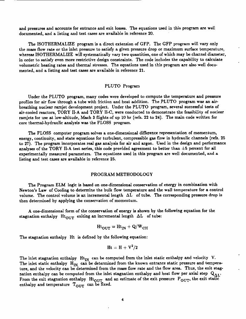
The ISOTHERMALIZE program is a direct extension of GFP. The GFP program will vary only
the mass flow rate or the inlet pressure to satisfy a given pressure drop or maximum surface temperature,
whereas ISOTHERMALIZE will systematically vary two quantities, one of which may be channel diameter,
in order to satisfy even more restrictive design constraints. The code includes the capability to calculate
volumetric heating rates and thermal stresses. The equations used in this program are also well docu-
mented, and a listing and test cases are available in reference 21.
PLUTO Program
Under the PLUTO program, many codes were developed to compute the temperature and pressure
profiles for air flow through a tube with friction and heat addition. The PLUTO program was an air-
breathing nuclear ramjet development project. Under the PLUTO program, several successful tests of
air-cooled reactors, TORY II-A and TORY II-C, were conducted to demonstrate the feasibility of nuclear
ramjets for use at low-altitude, Much 3 flights of up 10 hr (refs. 22 to 24). The main code written for
core thermal-hydraullc analysis was the FLOSS program.
The FLOSS computer program solves a one-dimensional difference representation of momentum,
energy, continuity, and state equations for turbulent, compressible gas flow in hydraulic channels (refs. 25
to 27). The program incorporates real gas analysis for air and argon. Used in the design and performance
analyses of the TORY II-A test series, this code provided agreement to better than ±5 percent for all
experimentally measured parameters. The equations used in this program are well documented, and a
listing and test cases are available in reference 25.
PROGRAM METHODOLOGY
The Program ELM logic is based on one-dimensional conservation of energy in combination with
Newton's Law of Cooling to determine the bulk flow temperature and the wall temperature for a control
volume. The control volume is an incremental length AL of tube. The corresponding pressure drop is
then determined by applying the conservation of momentum.
A one-dimensional form of the conservation of energy is shown by the following equation for the
stagnation enthalpy Htou T exiting an incremental length AL of tube:
Htou T = HtIN -t- Q/WcH
The stagnation enthalpy Ht is defined by the following equation:
Ht _-H ÷ V_/2
The inlet stagnation enthalpy HtIN can be computed from the inlet static enthalpy and velocity V.
The inlet static enthalpy HIN can be determined from the known entrance static pressure and tempera-ture, and the velocity can be determined from the mass flow rate and the flow area. Thus, the exit stag-
nation enthalpy can be computed from the inlet stagnation enthalpy and heat flow per axial step Q4L"From the exit stagnation enthalpy Htou T and an estimate of the exit pressure POUT, the exl_ static
enthalpy and temperature TOU T can be fixed.

Theheat flow per axial step QAL is computed from the specified internal power generation per fuelelement P, the specified number of coolant channels NCH, and the axial power shape factor PSF
Q=PSF*P/(L *NcH )*AL
Since the only remaining unknown in the determination of TOU T is the power shape factor, a correlation
must be provided for the power shape factor in terms of known quantities. The power shape factor is
typically derived from either reactor physics or experimental analyses.
Newton's Law of Cooling is shown by the following equation:
Q = h * A * (Tw - TAW )
The adiabaticwall temperature isdefinedwhere filmconditionsare evaluatedat the average of the wall
and adiabaticwall temperatures (ref.28):
TAW -- T b * (1 -}- 0.5 * Prf 1/3 * (Tb -- 1) * M_)
The form of Newton's law used to determine the wall temperature at the midpoint of an incremental step
is shown by the following equation:
T w = Q/(hA) + TAW
Since we are computing TW, a correlation must be provided for the heat transfer coefficient h in terms
of known quantities.
The pressure drop across an axial step is a combination of friction and momentum loss. The form of
the equation used is shown by the following (ref. 29):
AP = [W_H/A 2 * AL * f/DcH * (1/PiN -k 1/POUT) ] q-[W_H/A 2 * (1/Pou T - 1/PIN)]
A correlation must also be provided for the friction factor in terms of known quantities. The following
sections review a number of correlations used in the past to complete the solutions for the step exit tem-
perature, the step midpoint wall temperature, and the step pressure drop.
Correlations for the Heat Transfer Coefficient
The heat transfer coefficients are typically correlated by using the dimensionless Nusselt number.
The Nusselt number provides a measure of the convection heat transfer at the wall surface and is defined
by the following equation:
Nu D -- hD/k
Many correlations for Nusselt number have been developed from experimental data for a variety of gases.The general form of the local Nusselt number correlations for turbulent pipe flow is shown by the follow-
ing equation:
Nu v -_ C1 * Re C2 * Pr C3 * (Tw/Tb) C4 * (C5 + C6 * (X/D)C7) C8
The constants generally range from -1 to 1 and could be zero. The following paragraphs discuss the
correlations included in Program ELM.
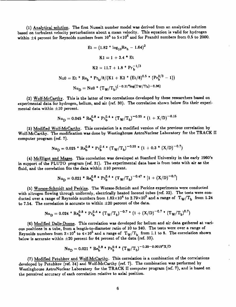
(1) Analytical solution. The first Nusselt number model was derived from an analytical solutionbased on turbulent velocity perturbations about a mean velocity. This equation is valid for hydrogen
within +4 percent for Reynolds numbers from 104 to 5×10⁶ and for Prandtl numbers from 0.5 to 2000.
Et = (1.82* lOgloReb - 1.64)2
KI=I +3.4*Et
K2 = 11.7 + 1.8 * Prb 1/3
Nu0 = Et * Re b * Prb/8/(K1 + K2 * (Et/8) °'s * (Pr_/3 - 1))
Nu D = Nu0 * (Tw/Tb) (-°'31*l°g(Tw/Tb)-°'3e)
(2) Wolf-McCarthy. This is the latter of two correlations developed by these researchers based on
experimental data for hydrogen, helium, and air (ref. 30). The correlation shown below fits their experi-
mental data within =£10 percent.
Nu D --0.045 * Re 0"8 * Pr_ "4 * (Tw/Tb) -0"ss * (1 + X/D) -0"15
(3) Modified Wolf-McCarthy. This correlation is a modified version of the previous correlation byWolf-McCarthy. The modification was done by Westinghouse AstroNuclear Laboratory for the TRACK II
computer program (ref. 7).
Nu D = 0.025 * Re 0"s * Pr_ "4 * (Tw/Tb) -0"5s * (1 + 0.3 * (X/D) -0"7)
(4) McEligot and Magee. This correlation was developed at Stanford University in the early 1960'sin support of the PLUTO program (ref. 31). The experimental data base is from tests with air as the
fluid, and the correlation fits the data within +10 percent.
Nu D -0.021 * Re 0"s * Pr_ "4 * (Tw/Tb) -0"47 * [1 + (X/D) -0"7]
(5) Worsoe-Schmidt and Perkins. The Worsoe-Schmidt and Perkins experiments were conducted
with nitrogen flowing through uniformly, electrically heated Inconel tubes (ref. 32). The tests were con-ducted over a range of Reynolds numbers from 1.83x10⁴ to 2.79×10⁵ and a range of Tw/T b from 1.24
to 7.54. The correlation is accurate to within +20 percent of the data.
Nu D = 0.024 * Reb0"s * Pr 0"4 * (Tw/Tb) -0"7 * (1 + (X/D) -0"7 * (Tw/Tb) 0"7)
(6) Modified Daile-Donne. This correlation was developed for helium and air data gathered at vari-ous positions in a tube, from a length-to-diameter ratio of 10 to 240. The tests were over a range of
Reynolds numbers from 3×10⁴ to 4x10 s and a range of Tw/T b from 1.1 to 8. The correlation shown
below is accurate within ±20 percent for 64 percent of the data (ref. 33).
Nu D = 0.021 * Re 0"s * Pr_ "4 * (Tw/Tb) -0"29-0"°°lg'X/D
(7) Modified Petuhkov and Wolf-McCarthy. This correlation is a combination of the correlations
developed by Petuhkov (ref. 34) and Wolf-McCarthy (ref. 7). The combination was performed byWestinghouse AstroNuclear Laboratory for the TRACK II computer program (ref. 7), and is based on
the perceived accuracy of each correlation relative to axial position.

X/D < 80:
Nu D = 0.0212 * Re_ "s * Pr 0"4 * (Tw/Tb) 0"11s59+0"0071465(X/D)-0"0000270s3'X'X/D/D
80 < X/D < 260:
Nu D --- (0.0212 -}- 0.000211'(X - 0.2032)) * Re 0"8 * Pr_ "4. (Tw/Tb) -0"55
260 < X/D:
Nu D -- 0.025 * Re_ '8. Pr_ "4 * (Tw/Tb) -0"55
(8) Williamson_ Bartlit_ and Thruston. This correlation was developed at Los Alamos ScientificLaboratory in the late 1960's and is accurate within ±20 percent for 63 percent of the data (ref. 35).
Tw/T b < 1.8:
Nu D : 0.023 * Re_ "8 * Pr_ "4 * (Tw/Tb) -0"765
Tw/T b > 1.8:
Nu D --- 0.023 * Re_ "s * Pr 0"4 * (Tw/Tb) -0"2 * 0.7
(9) Taylor equation. The following correlation was developed by M. Taylor at NASA Lewis ResearchCenter from hydrogen heat transfer measurements (ref. 36). The correlation was developed by using data
with wall temperatures from 114 to 5600 °R and temperature ratios to 23. The correlation is valid forReynolds numbers from 7.5x 10³ to 1.38x 10⁷ and is most accurate at inlet pressures higher than 530 psi.
The equation is accurate within +25 percent for 87 percent of the experimental data. The Taylor equa-tion was used extensively by Los Alamos Scientific Laboratory in the early 1970's in developing their
Small Engine Concept (ref. 37).
Nu D : 0.023 * Re_ "s * Pr_ "4 * (Tw/Tb) -0"57-1"59*D/X
(I0)Wolf-McCarthy II. This isthe earlierofthe two correlationsdeveloped by theseresearchers
based on experimentaldata fora hydrogen flow in a electricallyheated stainlesssteeltube (ref.38). The
correlation,shown below,was developed over a range ofReynolds numbers from 7800 to 1 500 000 and a
range of Tw/T b from 1.5to 2.8.
Nu D -0.023 * Re 0"s * Pr 0"4 * (Tw/Tb) -0"3
Correlations for the Friction Factor
Many correlations for the dimensionless friction factor have been developed from analysis and experi-
mental data for a variety of gases. However, no single correlation or equation form appears to work well
across the broad range of experimental data. The following paragraphs discuss the correlations incor-
porated into Program ELM.

(1) Analytical solution. The first friction factor model was derived from an analytical solution basedon turbulent velocity perturbations about a mean velocity. This equation is valid, for Re_ from 1.4 × 10³
to 10 e and for Prandtl numbers from 0.5 to 2000, within ±3 percent for hydrogen.
Et = (1.82 * logl0Re b - 1.64) 2
Re w = 4 * WCH/(r * D * _) * (Tw/Tb) -2
Re'- (Rew) -0"38
f-- Et * (Tw/Tb) -°'e+5"e*Re'
(2) GRAPH-I-TITE G. The correlation shown below was developed by Aerojet-General Corporationfor the GRAPH-I-TITE G fuel elements with a roughness of 0.006 from Reynolds numbers 2300 to 100 000
(ref. 39).
f = 0.25 * (0.0345 + 363/Re 1"25)
(3) Basic friction factor. The following correlation was developed for friction factors in smooth tubeswith turbulent flow. This equation is valid for data with Reynolds numbers from 5000 to 200 000.
f = 0.046/Re 0"2
(4) Moody diagram with input roughness. This correlation was developed to model the Moody Dia-
gram for friction factor and incorporates a variable surface roughness (ref. 40).
f = 0.0055 * [1 + (20 * _ + 1 000 000/Ref) 1/3]
(5) Basic friction factor and roughness correction. During analysis of channel pressure drop for the710 Program, the basic friction factor correlation was modified by a multiplier to account for surface
roughness (ref. 41).
f = 1.35 * (0.046/Re_ "2)
(6)Koo equation.
smooth tube (ref.42).
The following correlation is the Koo equation developed for the friction factor in a
f = 0.0014 + 0.125/Re_ "32
(7) Moody friction with 6 = 0.006. A correlation based on the Moody diagram for a roughness of
0.006 was developed (ref. 4) and is shown in the following equation. The relative roughness of 0.006 was
measured experimentally from a passage of a fuel element split axially.
f = 0.25 * (0.03172 + 7.2/Re_ "'rs)
(8) Taylor correlation I. The Taylor correlation is presented for the friction factor in a smooth tube
(refs. 43 and 44). This was developed from a data base of hydrogen, air, nitrogen, and helium experi-ments with a Reynolds number in the range 3000 to 187 000. The accuracy is within ±10 percent for the
data base.

Rew -- 4 * WCH/_/D//_w* (Tb/Tw)
f-- (0.0014 + 0.125/Re°'32)(Tw/Tb) -°'s
(9) Taylor correlation II. The correlation here is the Taylor correlation incorporated in the TNT-II
program, which was used to predict the performance of the NRX reactor series of the NERVA program
(ref. 45).
Re w=4* WCH/(_*D* _)*Tw/T b
fA = 0.0014 -{-0.125/(495/61"138) 0.32
fB = 0.0014 + 0.125/(495/el"13S/20) 0"32
p -- Rew/(495/_ 1.13s)
Y = (fB - fA) * p0.3-0.1*V
fl ----((0.0014 % 0.125/Re: "32) * (Tw/Tb) -0"5 + y)0.5
ft = (2.28 + 4 * log10[(6 + 4.675/Rew/fl)-l)] -2
2000 < Re w < 3000:
3000 < Rew:
f = ft * (Re w - 2000)/1000 + 16/Re w * (1 - (Re w - 2000)/1000)
f=ft
(10) Moody friction with e -- 0.004. A correlation based on the Moody diagram for a roughness of
0.004 was developed (ref. 3) and is shown below. The relative roughness of 0.004 was measured experi-mentally from a passage of an unfueled element split along the axis.
Y -- LN(Re B * 10 000 000) + 10
f-- (0.1552 - 0.04412 * Y + 0.005318 * y2 _ 0.0002881 * y3 + 0.000005903 * Y4)/4
Regression Models for the Axial Power Shape Factor
The axial power shape factor, which is a function of the reactor physics, is required to calculate the
internal heat generation, or fission density, at each axial station relative to the average level of the entire
element. For axial flow, right-circular-cylinder fission reactor cores without end-moderation, the axial
power shape factor distribution is closely approximated by a sine wave. The power shape factor (PSF)
values ranged from 0.2 to 1.4 for the NERVA reactors.
Program ELM incorporates eight fourth-order regression models of published power shape factor data.
Figure 2 shows a sample comparison of four of the models with experimental data, while figure 3 presents
a comparison of all the models. Table I presents the various regression models and their coefficients.
9

Theregressionmodelsweredevelopedfrom publishedexperimentaldata for averagepower fuel elements
(refs. 46 to 49). The general form of the fourth-order polynomial regression model which was used isshown as follows:
PSF = A + B*(X/L) + C*(X/L) 2 + D*(X/L) 3 + E*(X/L) 4
PROGRAM ELM STRUCTURE
Program ELM (ref. 50) was written in standard Fortran 77 and has been operated under a variety
of operating systems on computers from IBM PC-compatibles to VAX mainframes. The overall structure
and logic for Program ELM is shown in figure 4, and a listing of the program is provided in the appen-
dix. The program listing does not include the real gas subroutine, PH2, since this model is already docu-
mented (ref. 51) or can be easily replaced by any routine which solves for density, enthalpy, molecularweight, and viscosity, given pressure and temperature. The code incorporates a user-interactive interfacefor selection of the three correlations and for displaying program results. Moreover, the program accesses
an input file (table II) containing geometry and other parameters, and an output file (table III) contain-
ing the program results.
Algorithm
The program commences by echoing a program identification header to the screen, and this is fol-lowed by a prompt for the input and output file names. Next, the user is prompted for the number whichselects the desired correlation for Nusselt number, friction factor, and power shape factor. At this point,
the program reads the input file.
The firstcalculationmade isto calculatethe fuelelement entrancelosses.
for entranceor exitpressurelossisshown as follows:
AP=0.5*C L*p*V 2
The general equation used
The entrance loss coefficient CL,IN can be input, if known, or estimated based on the following relation,where A2 is the upstream flow area and A1 is the channel flow area (ref. 52):
CL,IN -- 1.5 -- 0.5 * AI/A2 - (A1/A2) 2
After an initial estimate of the step exit temperature, exit pressure, and wall temperature, the code
computes the current axial position. With the estimate of the exit condition and knowledge of the step
entrance parameters, the bulk (average) step pressure and temperature can be computed and the gas
properties can be determined by a state properties subroutine. In Program ELM, the state properties
were determined by subroutine PH2. This routine calculates the state properties of parahydrogen from
saturated liquid to a dissociated gas.
Once the bulk properties are determined, the Nusselt number, friction factor, and power shape factor
are computed from the specified correlations. With these values, the heat flux for the step AL can be
fixed, and the exit temperature can be determined. Since this latter parameter was initially guessed and
used to compute the bulk temperature, the new exit temperature is compared to the guessed value. If the
absolute difference is greater than 0.1 percent, then the bulk temperature is recomputed using the new
value and the cycle iterates until convergence is met.
10

Once convergence on exit temperature is met, the wall temperature is computed. Since this param-
eter was initially guessed and used in the Nusselt number correlation, the new exit temperature is com-
pared to the guessed value. If the absolute difference is greater than 0.1 percent, then the Nusselt number
is recomputed using the new value of wall temperature, and the cycle iterates until convergence is met.
Once convergence on wall temperature is met, the step inlet and outlet gas properties are computedfrom the known inlet conditions, the computed exit temperature and the guessed exit pressure. Finally,
the exit pressure is computed. Since this parameter was initially guessed and then used to determine exit
gas properties for the calculation of exit pressure, the new exit pressure is compared to the guessed value.
If the absolute difference is greater than 0.1 percent, then the exit gas properties are recomputed using
the new value of exit pressure, and the cycle iterates until convergence is met.
Once convergence is met on exit pressure, the parameters computed are echoed to the screen and
stored in an array, the next axial position is computed, and the entire process repeats. The process iter-
ates until the current position equals the specified channel length. Prior to writing the parameters to the
output file, the program takes care of the following bookkeeping matter.
Recall that the equations used in ELM determine the step exit temperature, the step exit pressure,
and the step midpoint wall temperature. Therefore, the wall temperatures stored in the array must be
corrected to the step exit location. This is done by averaging two adjacent step midpoint wall tempera-
tures to calculate the step exit wall temperature between the midpoints. The resultant values are
restored in the array, which is then written to the output file.
The last computation by the program is to calculate the fuel element exit pressure loss. The exit
loss coefficient C L OUT can either be input or be calculated from the following relation, where A1 is thechannel flow area and A2 is the downstream flow area (ref. 52).
CL,OU T = 2 * [A1/A2 - (AI/A2) 2]
Program Input Description
The main program input is read from a file assigned to Fortran unit 2. This file contains the geo-
metric and initial hydrogen state parameters required for a successful program execution. The first 65
columns of each input file line contains a brief description of the parameter which follows in the next 14columns. The following sections describe each input parameter.
POWER. Total thermal power added to the hydrogen for the fuel element, units are in watts.
PI__.NN.Plenum pressure at the fuel element entrance, in pounds per square inch.
TIN. Plenum temperature at the fuel element entrance, in degrees Rankine.
WCH. Total mass flow rate through the fuel element, in pounds per second.
DH. Coolant channel hydraulic diameter, in inches.
NCH. Number of coolant channels bored through each fuel element. This is a dimensionless parameter.
L. Total length of the fuel element, in inches.
11
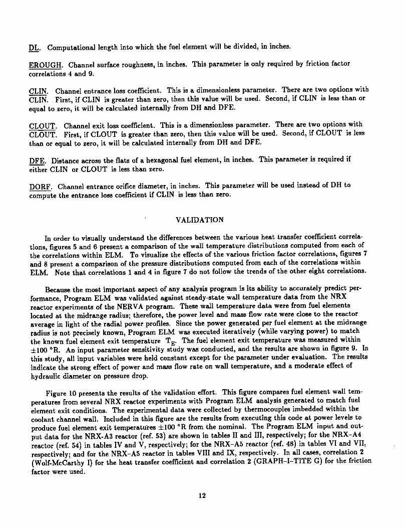
D_._L_L.Computationallength into which the fuel element will be divided, in inches.
EROUGH. Channel surface roughness, in inches. This parameter is only required by friction factor
correlations 4 and 9.
CLIN. Channel entrance loss coefficient. This is a dimensionless parameter. There are two options with
CLIN. First, if CLIN is greater than zero, then this value will be used. Second, if CLIN is less than or
equal to zero, it will be calculated internally from DH and DFE.
CLOUT. Channel exit loss coefficient. This is a dimensionless parameter. There are two options with
CLOUT. First, if CLOUT is greater than zero, then this value will be used. Second, if CLOUT is less
than or equal to zero, it will be calculated internally from DH and DFE.
DFE. Distance across the fiats of a hexagonal fuel element, in inches. This parameter is required if
either CLIN or CLOUT is less than zero.
DORF. Channel entrance orifice diameter, in inches. This parameter will be used instead of DH to
compute the entrance loss coefficient if CLIN is less than zero.
VALIDATION
In order to visually understand the differences between the various heat transfer coefficient correla-
tions, figures 5 and 6 present a comparison of the wall temperature distributions computed from each ofthe correlations within ELM. To visualize the effects of the various friction factor correlations, figures 7
and 8 present a comparison of the pressure distributions computed from each of the correlations withinELM. Note that correlations 1 and 4 in figure 7 do not follow the trends of the other eight correlations.
Because the most important aspect of any analysis program is its ability to accurately predict per-
formance, Program ELM was validated against steady-state wall temperature data from the NRX
reactor experiments of the NERVA program. These wall temperature data were from fuel elementslocated at the midrange radius; therefore, the power level and mass flow rate were close to the reactor
average in light of the radial power profiles. Since the power generated per fuel element at the midrangeradius is not precisely known, Program ELM was executed iteratively (while varying power) to match
the known fuel element exit temperature T E. The fuel element exit temperature was measured within±100 °R. An input parameter sensitivity study was conducted, and the results are shown in figure 9. In
this study, all input variables were held constant except for the parameter under evaluation. The results
indicate the strong effect of power and mass flow rate on wall temperature, and a moderate effect of
hydraulic diameter on pressure drop.
Figure 10 presents the results of the validation effort. This figure compares fuel element wall tem-peratures from several NRX reactor experiments with Program ELM analysis generated to match fuel
element exit conditions. The experimental data were collected by thermocouples imbedded within thecoolant channel wall. Included in this figure are the results from executing this code at power levels to
produce fuel element exit temperatu_res ±100 °R from the nominal. The Program ELM input and out-
put data for the NRX-A3 reactor (ref. 53) are shown in tables II and III, respectively; for the NRX-A4
reactor (ref. 54) in tables IV and V, respectively; for the NRX-A5 reactor (ref. 48) in tables VI and VII,
respectively; and for the NRX-A5 reactor in tables VIII and IX, respectively. In all cases, correlation 2
(Wolf-McCarthy I) for the heat transfer coefficient and correlation 2 (GRAPH-I-TITE G) for the frictionfactor were used.
12

Each comparison in figure 10 shows the calculated wall temperatures below the experimental data.This error can be attributed to either the use of imbedded thermocouples to represent wall temperatures
or the roughness of the estimate for average fuel element mass flow rate. Figure 9 illustrates the largeeffect of mass flow rate variations.
CONCLUSIONS
A program has been developed and validated for modeling the steady-state pressure drop and tem-
peratures along an axial coolant channel with heat transfer to a compressible fluid. Program ELM wasused to evaluate various heat transfer coefficient and friction factor correlations on a common basis. As
validation, ELM was used to model NRX reactor coolant channels. The results from this analysis were
compared with experimental data for fuel element coolant channel wall temperature. The comparison
showed good agreement. Since ELM is small, fast, accurate, and portable, it can be used as a rapid
approximation tool for fuel element parametric studies. Moreover, ELM can be used to analyze general
flow through pipes with high wall heating rates.
13

APPENDIX.--PROGRAM LISTING
CCCCCCCCCCCCCCCCCCCCCC
CCCC
CCCCCCCCCCCC
CCCCCC
PROGRAM ELM
THIS PROGRAM PERFORMS AEROTHERMODYNAMIC ANALYSIS ON H2 GAS COOLEDNUCLEAR REACTOR CORE FUEL ELEMENTS. THE ANALYSIS IS BASED ONCONSERVATION OF ENERGY EQUATIONS WITH EXTENSIVE USE OF CORRELATIONSFOR THE CONVECTIVE HEAT TRANSFER COEFFICIENT, FRICTION FACTOR, ANDELEMENT AXIAL POWER DISTRIBUTION. THE ANALYSIS IS FOR AN AVERAGECOOLANT CHANNEL, SUCH AS AT A POINT IN THE CORE WHERE THE RADIAL
POWER OVER AVERAGE POWER RATIO IS UNITY.
THIS PROGRAM IS AVAILABLE THROUGH NASA'S COMPUTER SOFTWARE LIBRARY.
COSMIC. @ (404) 542-3265 AS PROGRAM # LEW-15423.
THE SUBROUTINE PH2 IS AVAILABLE THROUGH COSMIC AS LEW-1550S.
CURRENTLY:
1) NO ELEMENT ENTRANCE OR EXIT LOSSES ARE ACCOUNTED FOR.2) THE CHANNEL DIAMETER IS ASSUMED TO BE CONSTANT.3) CONVERGENCE TOLERANCES ARE SET TO I DEGREE RANKINE AND 1 PSi.
ORIGINATION: SEPTEMBER 12, 1991LAST MOD: APRIL 30. 1992
IMPLICIT REAL*8 (A-H,O-Z)REAL*8 L,K,NU,NCH.N USELT,MACHDIMENSION STORE(S000,7)CHARACTER DATE*20
DATA PCONV /O.OOt/,T CONV /O.OO1/,HCONV /O.O0001/DATA VERSION/1.03/, DATE/'APRIL 30. 1992"/
C.....OUTPUT PROGRAM BANNER TO SCREEN AND REQUEST I/O FILE NAMES
CALL BANNER(VERSION,DATE)
C.....SELECT NUSSELT NUMBER CORRELATIONINU = 0INU = NUSELT(DUMJ,D UM2,DUM3,DUM4.DUMS,DUM6,1N U)
C.....SELECT FRICTION FACTOR CORRELATION
ICF = 0ICF = CFRICT(DUM1,DUM2,DU M3,DUM4,DUMS,DUM6.DUMT.ICF)
C.....SELECT POWER SHAPING FACTOR CORRELATIONIPSF = 0
IPSF = PSFCAL(DUMI,IPSF)
WRITE(6,t) VERSION,DATEWRITE(3,1) VERSION,DATE
1 FORMAT(' PROGRAM ELM',/,1' VERSION '.FS.2./.
t' ',A20,/)
C.....READ INPUT IN ENGLISH UNITS
CALL READER(TIN,PIN,DH,POWER,NCH,WCH,L.DL,EROU GH,CLIN,CLOUT,! DFE,DORF}
WRITE(6,2)WRITE(3,2)
2 FORMAT(I lX,' X (in.)',' Tb (R)',' Tw (R)'.' Gum. P(W)',
14

1' Re ',' Pb (psi)',' MACH ',/,1 1X,' ........ ',' ........ ',' ........ ',' ......... ',
1'- ....... ',' ........ ',' ......... ")
C ..... CONVERT INPUT
TIN = TIN/1.8PIN - PIN * 6894.7572
DH - DH * 0.0254
DFE = DFE * 0.0254
DORF = DORF* 0.0254
WCH = WCH * 0.45359237/NCHL = L * 0.0254
DL = DL * 0.0254
EROUGH = EROUGH* 0.0254
C ..... INITIALIZATION
ISTEP = 1
QSUM = 0.TBN = TIN
TWN = TIN
X = -DL/2.AREA = 3.14159*DH*DL
WOA2 = (WCH/(3.I4159*DH*DH/4))**2C..... COMPUTE ENTRANCE AND EXIT LOSS COEFFICIENTS
AFE = 1.5*DFE*DFE*0.57735
IF (DORF.LE.0.) DORF = DHADH = 3.14159*DORF*DORF/4.*19.
IF (CLIN.LT.0.) CLIN = 1.5-0.5*ADH/AFE-(ADH/AFE)**2
IF (CLOUT.LT.0.) CLOUT = 2.*(ADH/AFE - (ADH/AFE)**2)C ..... COMPUTE ENTRANCE LOSSES
IDUM -- 0
CALL P H2(DUM1,PIN,TIN,RHO,VIS,CP,DUM2,DUM3,DUM4,DUM5,1DUM)
U = 4.*WCH/RHO/3.1415g/DH/DH
PIN = PIN - CLIN*RHO*U*U/2.PBN = PIN
POUTN = PIN - 30000.
WRITE(6,8000) 0.. TIN*I.8, TIN*l.8,0.,0.,PIN/6894,7572,0.
WRITE(3,8000) 0., TIN*I.8, TIN*l.8,0.,O.,PIN/6894.7572,0.
C ..... BEGIN ITERATION
100 X = X + DL
C ..... DETERMINE FLOW PROPERTIES USING BULK STATIC TEMPERATURE AND
C BULK STATIC PRESSURE
200 TB = TBN
PB = PBN
IDUM = 0
CALL PH2(DUM1,PB,TB, RHOb,VIS,CP,PR,SOS,K,DUM5,1DUM)
U = 4.*WCH/RHOb/3.14159/DH/DH
MACH = U/SOS
REb = RHOb*U*DH/VIS
300 TW = TWN
C..... COMPUTE NUSSELT NUMBER
NU = NUSELT(REb.PR,TW.TB,X,DH,INU I
HTC = (K/DH)INUC ..... COMPUTE FRICTION FACTOR
f = CFRICT (REb,TW,TB,DH.EROUGH,PB,WCH.ICF)C ..... COMPUTE POWER SHAPE FACTOR
XOL = X/L
PSF = PSFCAL(XOL,IPSF)C ..... COMPUTE POWER ADDED TO FLOW ACROSS STEP
15
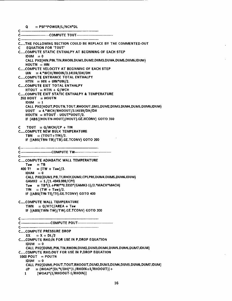
Q = PSF*POWER/L/NCH*DL
C.......................... COMPUTE TOUT .................................C ...................... "_°" .............................................
C.....THE FOLLOWING SECTION COULD BE REPLACE BY THE COMMENTED-OUTC EQUATION FOR 'TOUT'C.....COMPUTE STATIC ENTHALPY AT BEGINNING OF EACH STEP
IDUM = 0
CALL PH2(HIN,PIN.TIN.RHOIN.DU M1,DUM2.DUM3.DUM4.DUMS.DUM6.1DUM)HOUTN = HIN
C.....COMPUTE VELOCITY AT BEGINNING OF EACH STEP
UIN = 4.*WCH/RHOIN/3.14159/DH/DHC.....COMPUTE ENTRANCE TOTAL ENTHALPY
HTIN = HIN + UIN*UIN/2.C.....COMPUTE EXIT TOTAL ENTHALPY
HTOUT = HTIN + Q/WCHC.....COMPUTE EXIT STATIC ENTHALPY & TEMPERATURE
3S0 HOUT = HOUTNIDUM = 1
CALL PH2(HOUT,POUTN,TOUT,RHOOUT,DM1,DUM2,DUM3,DUM4,DUMS,DUM6,1DUM)UOUT = 4.*WCH/RHOOUT/3.J4159/DH/DHHOUTN = HTOUT - UOUT*UOUT/2.IF (ABS{(HOUTN-HOUT)/HOUT).GE.HCONV) GOTO 350
C TOUT = Q/WCH/CP + TINC.....COMPUTE NEW BULK TEMPERATURE
TBN = (TOUT+TIN)/2.
IF ((ABS(TBN-TB)/TB).GE.TCONV) GOTO 200
C .......................................................................
C............................ COMPUTE TW .................................
C .......................................................................
C.....COMPUTE ADIABATIC WALL TEMPERATURETaw = TB
400 Tf = (TW + Taw)/2.IDUM = 0
CALL PH2(DUM1,PB,Tf, RHOf, DUM2,CPf, PRf,DUM4,DUMS,DUM6,1DUM)GAMH2 = 1./(1.-4949.999/CPf)Taw = TB (1.+PRf 0.3333 (GAMH2-1)/2. MACH MACH)TfN = (TW + Taw)/2.
IF ((ABS(TfN-Tf)/Tf).GE.TCONV) GOTO 400
C.....COMPUTE WALL TEMPERATURE
TWN = Q/HTC/AREA + Taw
IF ((ABS(TWN-TW)/TW).GE.TCONV) GOTO 300
C .......................................................................
C........................... COMPUTE POUT ................................C ...... - ................................................................
C..... COMPUTE PRESSURE DROP
XX = X + DL/2C..... COMPUTE RHO,IN FOR USE IN P,DROP EQUATION
IDUM = 0
CALL PH2(DUM1,PIN,TIN,RHOIN,DUM2,DUM3,DUM4,DUMS,DUM6,DUMT,IDUM)C.....COMPUTE RHO,OUT FOR USE IN P,DROP EQUATION1000 POUT = POUTN
IDUM = 0
CALL PH2{DUM1,POUT.TOUT,RHOOUT,DUM2,DUM3,DUM4,DUMS,DUM6.DUM7,1DUM)dP = (WOA2* (DL*f/DH)* (1./RHOIN+t/RHOOUT)}+
1 (WOA2*(I/RHOOUT-1/RHOIN))
16

POUTN=PIN-dPIF((ABS(POUTN-POUT)/POUT).GT.PCONV)GOTO1000PBN = (POUT+PIN)/2
C..... ITERATE UNTIL NEW BULK EQUALS OLD BULK (RECALL THAT INITIALLYC TWALL IS COMPUTED WITH GUESSED BULK PRESSURE)
IF ((ABS(PBN-PB)/PB).GE.PCONV) GOTO 200C..... ROUGH ESTIMATE FOR BULK PRESSURE OF NEXT STEP
PBN = POUT + dP/2.
C..... STEP PROPERTIES CONVERGED
WRITE(6,8000) XX'39.3701, TOUT*I.8, TW*l.8,QSUM,REb,POUT/6894.75721 ,MACHQSUM = QSUM +
STORE(ISTEP,1) =STORE(ISTEP,2) =STORE(ISTEP,3) =STORE(ISTEP,4)STORE(ISTEP,5)STORE(ISTEP,6)STORE(ISTEP,7)
QXX'39.3701
TOUT*I.8TW*I.8
= QSUM= REb
= POUT/6894.7572= MACH
ISTEP = ISTEP + 1
IF (ISTEP.GT.5000) WRITE(6,*) ' ERROR - TOO MANY STEPS FOR ARRAY'.1 ' STORE, PLEASE INCREASE ITS SIZE.'TIN = TOUTPIN = POUT
IF ((XX+DL/2).LT.L) GOTO 100C.....CORRECT FOR EXIT LOSSES
U = 4.'WCH/RHOOUT /3.14159/DH/DHPOUT = POUT- CLOUT*RHOOUT*U*U/2.STORE(ISTEP-1,6) = POUT/6694.7572
C..... CORRECT WALL TEMPERATURE FROM STEP MIDPOINT TO STEP EXIT BY AVERAGING
DO 7990 I = t, ISTEP-2STORE(I,3) = (STORE(I,3)+STORE(I+I,3))/2.
7990 CONTINUEC.....CORRECT EXIT WALL TEMPERATURE BY EXTRAPOLATING
STORE(ISTEP-1,3) = STORE(ISTEP-1,3) -I-1 (STORE(ISTEP-1,3)-STORE(ISTEP-2,3))/2WRITE(3,8000) ((STORE(I,J),J=t,7),I=I,ISTEP-1)
8000 FORMAT(tX,4F10.2,F10.0,F10.2,F10.3)WRITE(6,8010) QSUM*NCH
8010 FORMAT(31X,' .......... ',/,31X,Ft0.t,' = POWER/ELEMENT',/)WRITE(3,80t0) QSUM*NCHWRITE(6,*) ' (NOTE: SEE OUTPUT FILE FOR PRECISE OUTPUT AT EACH',! ' STATION.)'
STOPEND
REAL*8 FUNCTION NUSELT(REb.PR,TW,TB,X,DHolNU)CCCC FUNCTION NUSELTCC ...............CC THIS FUNCTION COMPUTES THE NUSSELT NUMBER GIVEN BULK FLOW CONDITIONS.CC
17

CCCC
CCCC
AUTHOR: JAMES T. WALTON, NASA LEWIS RESEARCH CENTER• ORIGINATION: SEPTEMBER 16, 1991
LAST MOD.: NOVEMBER 25, 1991
IMPLICIT REAL*8 (A-H.O-Z)REAL*8 Kt.K2,NU0
IF (INU.EQ.0) GOTO 8000GOTO (1,2,3,4,5,6,7,8,9,10). INUGOTO 9990
C.....LOCAL NUSSELT NUMBER BASED ON ANALYTICAL SOLUTION. VALID OVERC 10000<RE<5000000, .5<PR<2000, WITHIN +-4% FOR H2.
C (PETUKHOV, B.S.: HEAT TRANSFER AND FRICTION IN TURBULENT PIPE FLOW.C ADVANCES IN HEAT TRANSFER, ACEDEMIC PRESS, NEW YORK, 1970.
1 IF ((REb.LT.10OO0.).OR.(REb.GT.5000000.)) WRITE(6,9900)INU,REbET = (1.82* DLOG10(REb)-l.64)** (-2.)KI = 1. + 3.4*ET
K2 = 11.7 + 1.8'PR**(-.33333)Nu0 = ET* REb* PR/8./(KI+K2*SQRT(ET/8.)* (PR** (.6667)-1.))NUSELT = NuO*(TW/TBI**(-.3t*DLOG10(TW/TB)-.36 )GOTO 9999
C.....LOCAL NUSSELT NUMBER FOR TURBULENT FLOW IN SMOOTH PIPES DERIVED FROMC EXPERIMENTAL DATA FOR HIGH TEMPERATURE HYDROGEN, HELIUM, AND AIR.C ACCURATE WITHIN +-10%.
C (WOLF, H.: McCARTHY. J.R.: HEAT TRANSFER TO HYDROGEN AND HELIUM WITHC WALL TO FLUID TEMPERATURE RATIOS TO 11.09. ROCK.DYN. RR-60-12, 12/60.C REF. BY BUSSARD, R.W.; DELAUER, R.D.: FUNDEMENTALS OF NUCLEAR FLIGHT.C McGRAW-HILL NEW YORK. 1965.)
2 IF (REb.LT.2300) WRITE(6.9900) INU.REbNUSELT = .045' REb**0.8* PR**0.4* (TW/TB) ** (-0.55)* (1.+ X/OH)** (-0.15)GOTO 9999
C.....LOCAL NUSSELT NUMBER BASED ON MODIFIED McCARTHY-WOLF
C (REFERENCED IN TRACK II- WANL-TME-2697, MAY 1970.)3 IF (REb.LT.1200)1 NUSELT = (4.36 + (O.036*REb*PR*DH/X)/(1.+0,001*REb*PR*DH/X))*1 (TW/TB)**.25IF (REb.LT.1200.) GOTO 9999IF ((TW/TB).GT.3.5) WRITE(6,99Ot)INU,TW/TBNUSELT = O.025*REb**O.8*PR**O.4*(TB/TW)**(0.55)*(t.+.3*
1 (X/OH)**(-.7))GOTO 9999
C.....LOCAL NUSSELT NUMBER FOR TURBULENT FLOW IN PIPES.C ACCURATE WITHIN +-10%.
C (McELIGOT, D.M.; MAGEE, P.M.: AEROTHERMODYNAMIC STUDIES AT HIGHC TEMPERATURE. STANFORD DEPT OF M.E., NUCLEAR ENGINEERING LABORATORY,
C TRN 326-1, JUNE 1962. REF. BY TORY IIC- UCRL-12069)
4 IF (REb.LT.2300) WRITE(6,9900)INU,REbNUSELT = .021' REb* *0.8* PR* *0.4*(TW/TB)** (-0.47)* (1.+X/D H** (-0.7))GOTO 9999
C.....NUSSELT NUMBER FROM WORSOE-SCHMIDT AND PERKINS CORRELATION. THIS
C RELATION MAY HAVE BEEN DEVELOPED BASED ON A NITROGEN DATA IN AC CONSTANT ELECTRICALLY HEATED INCONEL TUBE WITH AN OVERALL L/D=160.
C 18300<RE<279000, t.24<TW/TB<7.54, ACCURACY WITHIN +-20%.C (PERKINS, H.C.; WORSOE-SCHMIDT, P. INTERN. J. HEAT MASS TRANSFER,C 8, NO. 7, 1011-t031, 1965. REF. BY PEWEE-1 - LA-4217-MS)
18
5 IF (REb.LT.18300.) WRITE(6,9900)INU,REbNUSELT = .024*REb**0.8*PR'*0.4*(TW/TB)**(-0.7)*(t.+X/DH**(-0.7)*
1 (TW/TB)**(.7))GOTO 9999
C..... LOCAL NUSSELT NUMBER CORRELATION FOR TURBULENT AND LAMINAR FLOW.
C THE TURBULENT RELATION IS A MODIFIED DALLE-DONNE CORRELATION DEVELOPED
C IN HELIUM AND AIR WITH A TUBE 10 < L/D <240, 200 < TIN < 2800 R,
C 1.1 < TW/TB < 8. THE REYNOLD RANGE IS 30000 < RE < 400,000 WITHC 64% OF THE DATA WITHIN +-20%.
C (MILLER, J.V.; TAYLOR, M.F.: IMPROVED METHOD OF PREDICTING SURFACEC TEMPERATURES IN HYDROGEN-COOLED NUCLEAR ROCKET REACTOR AT HIGH
C SURFACE-TO-BULK-TEMPERATURE RATIOS. NASA TN D-2594, 1965.
C KAYS, W.M.: NUMERICAL SOLUTIONS FOR LAMINAR-FLOW HEAT TRANSFER IN
C CIRCULAR TUBES. TRANS. ASME, VOL. 77, NOV. 1955, PP.1265-1274.
C REF. IN CLARK- NASA TM-X-1232)
6 IF (REb.LT.2300.)
! NUSELT = 4.36 + (0.036*REb*PR*DH/X)/(t.+0.0011*REb*PR*DH/X)
IF (REb.GE.2300.)
1 NUSELT = .021*REb**0.8*PR**0.4*(TW/TB)**(-0.29-0.0019*X/DH)GOTO 9999
C ..... WANL NUSSELT NUMBER CORRELATION WHICH IS A COMBINATION OF THE WORK
C DONE BY PETUHKOV AND THAT OF McCARTHY-WOLF,
C (TRACK II - A COMPUTER PROGRAM FOR TRANSIENT THERMAL ANALYSIS OFC FLOW SYSTEMS WITH MULTIPLE PARALLEL AND SERIES CHANNELS. WANL-TME-2697,
C MAY 1970.)
7 IF (REb.LT.1200)
1 NUSELT = (4.36 + (0.036*REb*PR*DH/X)/(X.+0.001*REb*PR*DH/X))*
1 (TW/TB)**.2S
IF (REb.LT.I_200.) GOTO 9999PXXX = 0.11859090909 + 0.007146590909*X/DH - 0.000027083333*
1 X=X/DH/DH
IF ((X/DH).LT.80.)
I NUSELT -- 0.0212*REb**.8*PR**.4*(TB/TW)**PXXX
IF (((X/DH).GE.80.).AN D.((X/DH).LE.260.))
1 NUSELT = (0.0212+0.000211*(X-.2032))*REb**.8*PR**.4*(TB/TW)**.SS
IF ((X/DH).GT.260.)
1 NUSELT = 0.025*REb*_.8*PR**.4*(TB/TW)**.5SGOTO 9999
C ..... LASL NUSSELT NUMBER CORRELATION 73% OF DATA WITHIN +-20%
C (WlLLIAMSON, K.D.; BARTLIT, J.R.; THRUSTON, R.S,: STUDIES OF FORCEDC CONVECTION HEAT TRANSFER TO CRYOGENIC FLUIDS. C.E.P. SYMPOSIUM,
C SERIES 87, VOL 64, 1968. REF. IN TRACK II - WANL-TME-2697)
8 IF (REb.LT.1200)I NUSELT = (4.36 + (0.036*REb*PR*DH/X)/(1.+0.001*REbtPR*DH/X))*
1 (TW/TB)**.25
IF (REb.LT.1200.} GOTO 9999C1 = 1.
C2 = 0.765
IF ((TW/TB).GE.1.8) C1 = 0.7
IF ((TW/TB).GE.1.8) C2 = 0.2
NUSELT = 0.023*REb**.8*PR**.4*CI*(TB/TW)**C2GOTO 9999
C..... NUSSELT NUMBER CORRELATION FROM TAYLOR EQUATION.
C (DURHAM, FRANKLIN P.: NUCLEAR ENGINE DEFINITION STUDY PRELIMINARY
C REPORT, VOL. II- SUPPORTING STUDIES (SMALL ENGINE). LA-5044-MS, 9/72)
9 NUSELT = 0.023*REb**.E*PR**.4*(TW/TB)** (-.57+I.59*DH/X)
19
GOTO 9999
C.....NUSSELT NUMBER CORRELATION FROM EARLY MCCARTHY & WOLF BASED ON H2 IN
C ELECTRICALLY HEATED STAINLESS STEEL TUBE (L/D = 67 OR 42.6). GOOD FOR
C 1.5 < TW/TB < 2.8 & 7800 < RE < 1500000.C (MCCARTHY, J.R.: WOLF, H.: FORCED CONVECTION HEAT TRANSFER TO GASEOUSC HYDROGEN AT HIGH HEAT FLUX AND HIGH PRESSURE IN A SMOOTH, ROUND,C ELECTRICALLY HEATED TUBE. ARS JOURNAL, P.423-425, APRIL 1960.
10 IF (REb.LT.7800.) WRITE(6,9900) INU,REbNUSELT = 0.023*REb**.8*PR**.4*(TW/TB)**(-.3)GOT, 9999
Coo=.,.°,,,,.,,.=,..,...IQ..o.°,,,o,,o,,,.o,°ooo,o,o.,,o,oo,oo,oo,,,,,.
8000 WRITE(6,8001)8001 FORMAT(/,/,/,/,/,/,/,/,/,/,/,/,/,/,/,/,/,/,/,/,/,/,
1' SELECT NUSSELT NUMBER CORRELATION',/,2" -................................ '././,212X,'(1) PETUKHOV ANALYTICAL SOLUTION (+-4%)',/,312X,'(2) WOLF-McCARTHY RELATION (I) FOR SMOOTH CHANNELS (+-10%)',/,412X,'(3) WANL TRACK II CORRELATION FOR SMOOTH CHANNELS',/,512X,'(4) McELIGOT-MAGEE RELATION BASED ON AIR DATA'./,612X,'(S) WORSOE-SCHMIDT RELATION BASED ON N2 DATA',/.712X.'(6) MODIFIED DALLE-DONNE CORRELATION BASED ON HE & AIR'./.812X,'(7) WANL RELATION FROM PETUHKOV & McCARTHY-WOLF',/,910X,'* (8) LASL RELATION FROM WILLIAMSON-BARTLIT-THRUSTON',/,O12X,'(9) TAYLOR EQUATION USED IN SMALL ENGINE DESIGN EFFORT',/,IlIX.'(10) WOLF-McCARTHY RELATION (11)FOR SMOOTH CHANNELS',/,
I /,I,/,/./,/." ENTER NUMBER: ')READ(S.*) NUSELTWRITE(6,8002)
8002 FORMAT(/,/,/,/,/./,/,/,/,/,/,/,/,/,/,/,/,/./,/,/,/)WRITE(3,8003) NUSELT
8003 FORMAT(' NUSSELT NUMBER CORRELATION #'.F2.0)GOT, 9999
9900 FORMAT(' REYNOLDS NUMBER OUT OF SCOPE OF NUSSELT NUMBER',1 'CORRELATION #',12,/,' (CURRENT REb=',F10.1,')')
9901 FORMAT(' TW/TB OUT OF SCOPE OF NUSSELT NUMBER ',1' CORRELATION #',12,/,' (CURRENT TW/TB=',FI0.2.')')
9902 FORMAT(' STOP .... FUNCTION NUSELT COMPUTED NU < 0')
g990 WRITE(6.*) ' ERROR - INCORRECT VALUE FOR INU DETECTED IN',1 ' FUNCTION NUSELT'STOP
g99g IF (NUSELT.LE.0.) WRITE(6,gg02)IF (NUSELT.LE.0.) STOPRETURNEND
REAL*8 FUNCTION CFRICT(REb,TW,TB,DH,EROUGH,PB,WCH.ICF)CCCC FUNCTION CFRICTCC ...............CC THIS FUNCTION COMPUTES THE FRICTION FACTOR GIVEN BULK FLOW CONDITIONS.
CC
2O
CC AUTHOR: JAMES T. WALTON, NASA LEWIS RESEARCH CENTER
CC ORIGINATION: SEPTEMBER 17, 1991
CC LAST MOD.: NOVEMBER 25, 1991
CC
IMPLICIT REAL*8 (A-H,O-Z)
IDUM = -1
IF (ICF.EQ.0) GOTO 8000
GOTO (1,2,3,4,5,6,7,8,9,10), ICFGOTO 9990
FRICTION FACTOR FROM ANALYTICAL SOLUTION.
(PETUKHOV, B.S.: HEAT TRANSFER AND FRICTION IN TURBULENT PIPE FLOW.ADVANCES IN HEAT TRANSFER, ACEDEMIC PRESS, NEW YORK, 1970.
1 ET = (1.82*DLOGJ0(REb)-l.64)*'_(-2.)IDUM = 0
CALL PH2 (DUM.PB,TW.DUM1.VISW.DUM2.DUM3.DUM4.DUMS,DUM6.1DUM)
REw = 4.'WCH/3.141Sg/DH/VISw* (TB/TW)** 2
CFRICT -- ET' (TW/TB)'* (-.6+5.6*REw*' (-.38))GOTO 9999
C ..... FRICTION FACTOR CORRELATION FOR GRAPH-I-TITE G FUEL ELEMENTS AS
C DETERMINED BY AEROJET-GENERAL CORP. FOR A ROUGHNESS OF 0.006 AND
C FOR 2300<RE<100,000.
C (ANON.: COLD FLOW TEST OF REACTOR CLUSTER AND SUBSTITUTE REACTOR
C CLUSTER. AGC RN-S-00S8. REF BY CLARK NASA TMX).
2 IF (REb,GT.120000) WRITE(6,9900) ICF,REb
IF (REb.LT.2300) CFRICT = 16./REb
IF (REb.GE.2300)CFRICT = .25*(0.0345+363/REb**1.25)GOTO 9999
C ..... FRICTION FACTOR CORRELATION FOR SMOOTH TUBES.
C (BUSSARD, R.W.; DELAUER, R.D.: NUCLEAR ROCKET PROPULSION. MCGRAW-
C HILL, NEW YORK, 1958.)
3 IF (REb.GT.200000.) WRITE(6,9900) ICF,REbIF (REb.LT.S000) CFRICT = 16./REb
IF (REb.GE.5000) CFRICT = 0.046/REb'*.2GOTO 9999
C ..... FRICTION FACTOR FROM MOODY
C (ANON.: PEWEE-1 REACTOR TEST REPORT. LA-4217-MS, AUGUST 1969)4 IDUM = 0
TENG = (TW+TB)/2
CALL PH2(DUMJ,PB,TENG,DUM2,VISf, DUM3,DUM4,DUMS, DUM6,DUMT,IDUM)
REf = 4.'WCH/3.141Sg/DH/VISf
CFRICT = 0.005S*(J.+(20.*EROUGH+1000000./REf)**.333333333)GOTO 9999
C ..... FRICTION FACTOR FROM 710 PROGRAM CORRECTED FOR ROUGHNESS
C (ANON.: QUARTERLY PROGRESS REPORT (710 PROGRAM) NO. 1. GEMP-210,C MAY 1963.
5 CFRICT = 1.35*(0.046/REb**.2)GOTO 9999
C ..... KOO EQUATION FRICTION FACTOR FOR SMOOTH TUBE.
C (McADAMS. W.H.: HEAT TRANSMISSION. THIRD ED.. MCGRAW-HILL, 19S8.
C REF BY CLARK NASA TMX-1232)
6 IF (REb.LT.2300) CFRICT = 16./REb
21
IF (REb.GE.2300) CFRICT = 0.0014 + 0.125/REb**.32GOTO 9999
C.....FRICTION FACTOR FOR TUBE WITH RELATIVE ROUGHNESS OF 0.006 DEVELOPEDC FROM MOODY DIAGRAM.
C (CLARK, J.S.: COMPARISON OFPREDICTED AND EXPERIMENTAL OPERATINGC CHARACTERISTICS OF A NUCLEAR-ROCKET-CORE. NASA TM-X-1232, 1965.
7 IF (REb.LT.2300) CFRICT = 16./REbIF (REb.GE.2300) CFRICT = 0.2S*(O.O3172+?.2/REb**.?S)GOTO 9999
C
CCCCC
TAYLOR CORRELATION FOR FRICTION FACTOR IN A SMOOTH TUBE DEVELOPED FOR
H2, AIR, N2, HE AND GOOD FOR +-10% OVER 3000 < RE < 187000.
(TAYLOR, M.F.: A METHOD OF CORRELATING LOCAL AND AVERAGE FRICTIONCOEFFICIENTS FOR BOTH LAMINAR AND TURBULENT FLOW OF GASES THROUGH
A SMOOTH TUBE. INTL HEAT AND MASS TRANSFER SHORTER COMMUNICATIONS,
AUGUST 1967 (67A36941). REF BY TRACK II WANL-TME-2697.8 IDUM = 0
CALL PH2(DUM,PB,TW,DUM1,VISW,DUM2,DUM3,DUM4,DUMS,DUM6,1DUM)REw = 4.*WCH/3.14159/DH/VISw*TB/TWIF (REw.LT.1070) CFRICT = 16./RE*IF (REw.LT.1070) GOTO 9999CFRICT = (0.0014+0.12S/REw**.32)*SQRT(TB/TW)GOTO 9999
CCC
THE FRICTION FACTOR CORRELATION USED IN TNT-II CALCULATIONS FORROUGH SURFACE.
(ANON.: THERMAL AND FLUID FLOW ANALYSIS WANL TME-2753)9 IDUM = 0
CALL PH2 (DUM,PB,TW,DUM1,VISW,DUM2,D UM3,DUM4,DUMS, DUM6,1DUM)REw = 4.*WCH/3.14159/DH/VISw*TB/TWIF (REw.LT.2000) CFRICT = 16./REwIF (REw.LT.2000) GOTO 9999A = 49S./EROUGH**1.138FA = 0.0014 + .12S/A**.32FB = 0.0014 + .12S/(A/20.)**.32REwl = REw
IF (REw.GT.A) REwl = AP = REwl/AQ = .3 - .1*P
Y = (FB-FA)*P**QF1 = SQRT((0.0014+.12S/REw**.32)*SQRT(TB/TW) + Y)FT = (2.28+4.*DLOGlO((EROUGH+4.67S/REw/F1)**(-1)))**(-2.)
IF ((REw.GT.2000.).AN D.(REw.LT.3000.))1 CFRICT = FT*(REW-2000)/1000. + 16./REW*(1.-(REW-2000.)/1000.)IF (REw.GE.3000.) CFRICT = FTGOTO 9999
C.....FRICTION FACTOR FOR TUBE WITH RELATIVE ROUGHNESS OF 0.004 DEVELOPEDC FROM MOODY DIAGRAM.
C (CLARK, J.S.: ANALYTICAL AND EXPERIMENTAL STUDY OF STARTUP CHARAC.C OF A FULL-SCALE UNFUELED NUCLEAR ROCKET CORE ASSEMBLY.C NASA TM-X-123L J965.
10 IF (REb.LT.2300) CFRICT = 16./REbYX = DLOG(REb*10E-06)+10.IF (REb.GE.2300) CFRICT = (0.15S2-0.04412*YX+0.005318*YX*YX-
1 0.0002881' YX* YX* YX+0.000005903' YX*YX* YX* YX)/4.GOTO 9999
C°,..,°.,°...o4.,,.ogt,.,,,°o,o.°.°°, ..... .,°o.°,,,°,,'l,,,f.°,,°,,,,,°°
22

8000WRITE(6,SO01)8001FORMAT(/././././.I,/./././././././,/./././././././.
1' SELECTFRICTIONFACTORCORRELATION',/,2' -................................."././.212X.'(t) PETUKHOV ANALYTICAL SOLUTION'./.310X,'* (2) GRAPH-I-TITE G FUEL ELEMENT FRICTION RELATION ',/,412X,'(3) BASIC FRICTION FOR LAMINAR AND TURBULENT (e=0) ',/,512X,'(4) MOODY BASED FRICTION FACTOR (e=INPUT VALUE)',/,612X,'(5) BASIC FRICTION FOR TURBULENT * 1.35 CORRECTION',/,712X,'(6) KOO EQUATION FOR SMOOTH TUBES './.812X,'(7) RELATION FROM MOODY DIAGRAM FOR e=0.O06 ',/,
912X,'(8) TAYLOR RELATION FOR FRICTION FACTOR (e=0) ',/,Ot0X,'* (9) TAYLOR RELATION FOR FRICTION FACTOR (e=INPUT VALUE)',/,O11X,'(10) RELATION FROM MOODY DIAGRAM FOR e=0.004 ',/,
1 I,/,/,/,/,/,' ENTER NUMBER: ')READ(S,*) CFRICTWRITE(6,8002)
8002 FORMAT(/././././,/,/,/,/,/,/,/,/,/,/././,/,/./././)WRITE(3,8003) CFRICT
8003 FORMAT(' FRICTION FACTOR CORRELATION #',F2.0)GOTO 9999
"\
9900 FORMAT(' REYNOLDS NUMBER OUT OF SCOPE OF FRICTION FACTOR'.I 'CORRELATION #',12.l.' (CURRENT REb=',F10.1,')' I
9901 FORMAT(' STOP .... FUNCTION CFRICT COMPUTED f <= 0')
9990 WRITE(6,*) ' ERROR - INCORRECT VALUE FOR ICF DETECTED IN',11 " FUNCTION CFRICT'STOP
9999 IF (CFRICT.LE.0.) WRITE(6.9901)IF (CFRICT.LE.0.) STOPRETURNEND
REAL*8 FUNCTION PSFCAL(XOL,IPSF)CCCC FUNCTION PSFCALCC ...............CC THIS FUNCTION COMPUTES THE POWER SHAPE FACTOR GIVEN AXIAL POSITION.CCCC AUTHOR: JAMES T. WALTON. NASA LEWIS RESEARCH CENTERCC ORIGINATION: SEPTEMBER 19, 1991CC LAST MOD.: NOVEMBER 25, 1991CC
IMPLICIT REAL*8 (A-H,O-Z)
IF (IPSF.EQ.0) GOTO 8000GOTO (1,2,3,4,5,6,7,8). IPSFGOTO 9990
C.....POWER SHAPING FACTOR COEFFICIENTS FOR CURVE USED BY TNT-II PROGRAM.
C (NERVA ENGINE DATA AND DESIGN CONCEPTS, VOL. III - THERMAL AND FLUIDC FLOW ANALYSIS. WANL-TME-1798, JUNE 1968.)
1 A = 0.240243623548B = 3.18743980258C = 1.147836959S7D =-7.52353879018
23

E = 3.23771164993GOTO9999
C..... POWER SHAPE FACTOR COEFFICIENTS FOR CURVE OF NRX-A2 REACTOR.
C (NRX-A2 TEST FINAL REPORT. WANL-TNR-193, MARCH 1965.)2 A = 0.360742338891
B = 4.50215211498C =-4.94032044875D =-0.481081746774E = 0.768777777651
GOTO 9999
C.....POWER SHAPE FACTOR COEFFICIENTS FOR CURVE OF NRX-A3 REACTOR.
C (NRX-A5 REACTOR TEST ANALYSIS REPORT. WANL-TNR-219, MARCH 1967.)3 A = 0.388914519476
B = 4.02639441610C =°3.35296846791D =-2.71711572027E = 1.95396600540GOTO 9999
C.....POWER SHAPE FACTOR COEFFICIENTS FOR CURVE OF NRX-A4/EST REACTOR.
C (NRX-A5 REACTOR TEST ANALYSIS REPORT. WANL-TNR-219, MARCH 1967.)4 A = 0.523554259920
B = 3.11216568076C = 0.429960285933D =-9.51785121938E = 5.82723420430GOTO 9999
C..... POWER SHAPE FACTOR COEFFICIENTS FOR CURVE OF NRX-A5 REACTOR.
C (NRX-A5 REACTOR TEST ANALYSIS REPORT. WANL-TNR-219, MARCH 1967.)5 A = 0.203569633244
B = 5.59270800308C =-7.77244060348D = 2.39244292069E =-0.0106892741948GOTO 9999
C.....POWER SHAPE FACTOR COEFFICIENTS FOR CURVE OF NRX-A6 REACTOR.
C (NRX-A6 REACTOR TEST ANALYSIS REPORT. WANL-TNR-223, AUGUST 1968.)6 A = 0.342910797012
B = 3.85198430654C --0.721844448175D =-8.27798616356E = 5.09908210847GOTO 9999
C..... POWER SHAPE FACTOR COEFFICIENTS FOR CURVE OF PEWEE-! REACTOR.
C (PEWEE-1 REACTOR TEST REPORT. LA-4217-MS, JUNE 1969.)7 A = 0.315263743551
B = 4.01075764283C =-2.81198488737D =-2.13642616902E = 0.653731955838GOTO 9999
C.....POWER SHAPE FACTOR COEFFICIENTS FOR CURVE OF SMALL ENGINE REACTOR.
C (DURHAM, FRANKLIN P.: ENGINE DEFINITION STUDY. LA-S044-MS. VOL. I-III,
24

C SEPTEMBER1972.)8A = 0.370101535438
B = 4.33086012101C =-4.51483233018D =-0.0955935232165E = 0.0959623283744GOTO 9999
C oooo,..ooo,.,oo,,,oo,,,,o,,,o.o ..... .ooo°,o°,,,,o,o,,,o,,o,,,°, ...... •
8000 WRITE(6,8001)
8001 FORMAT(/,/././,/,/./,/,/,/,/./././,/,/,/./,/./,/,/.1' SELECT AXIAL POWER SHAPE CORRELATION'./.2" -................................... '././.212X.'(1) PROGRAM TNT-II NERVA MODEL CIRCA 1968'./.412X.'(2) NRX-A2 REACTOR MODEL BASED ON EXPERIMENTAL DATA'./,412X.'(3) NRX-A3 REACTOR MODEL BASED ON EXPERIMENTAL DATA'./.412X,'(4) NRX-A4/EST REACTOR MODEL BASED ON EXPERIMENTAL DATA'./,412X,'(5) NRX-A5 REACTOR MODEL BASED ON EXPERIMENTAL DATA',/.412X.'(6) NRX-A6 REACTOR MODEL BASED ON EXPERIMENTAL DATA'./.312X.'(7) PEWEE-1 REACTOR MODEL './,912X.'(8) SMALL ENGINE REACTOR MODEL './.o12x.' './.1 /.I.1.1.1.1.' ENTER NUMBER: ')READ(5.*) PSFCALWRITE(6.8002)
8002 FORMAT(/././,/./././././././././././,/,/,/,/./,/./)WRITE(3.8003) PSFCAL
8003 FORMAT(' POWER SHAPE FACTOR CORRELATION #'.F2.0)RETURN
9901 FORMAT(' STOP .... FUNCTION PSFCAL COMPUTED PSF <= 0')9990 WRITE(6.") ' ERROR - INCORRECT VALUE FOR IPSF DETECTED IN'.
1 ' FUNCTION PSFCAL'STOP
9999 PSFCAL = A + B*XOL + C*XOL*XOL + D*XOL*XOL*XOL + E*XOL*XOL*XOL*XOL
IF (PSFCAL.LE.0.) WRITE(6.9901)IF (PSFCAL.LE.0.) STOPRETURNEND
CCCCCCCCCCCCCCCCCCCC
SUBROUTINE BANNER(VERSION.DATE)SUBROUTINE BANNER
THIS SUBROUTINE WRITES THE STANDARD NASA PROGRAM BANNER PAGETO THE TERMINAL SCREEN.
AUTHOR: JAMES T. WALTON, NASA LEWIS RESEARCH CENTERORIGINATION: MAY 13. 1991LAST MODIFICATION: SEPTEMBER 17. 1991
IMPLICIT REAL*8 (A-H.O-Z)CHARACTER JUNK 12.DATE 20,FILEINP 12.FILEOUT 12
DATA FILEIN P/'ELM.IN P'/.FILEOUT/'ELM.OUT'/
WRITE(6.t0) VERSION, DATE
25

10FORMAT(/./,/,/,/,/,/,/,117X,'NATIONALAERONAUTICSANDSPACEADMINISTRATION',/,22gX,'LEWISRESEARCHCENTER',/,332X,'CLEVELAND,OHIO',/,/,/,416X,' PROGRAMELM',/,416X,' LEW-15423',/.417X.'NUCLEARROCKETENGINEFUELELEMENTANALYSIS',I.I.I,534X,'VERSlON',F4.2,/,/,/,/,/,lSX,6'AUTHOR:JAMEST.WALTON,NASALEWISRESEARCHCENTER',/,/,726X,'ORIGINATION:SEPTEMBER12,1991',/,S26X.'VERSIONDATE:',A20./,/,/,/,/,9 26X,'STRIKE <ENTER> TO CONTINUE....')
READ(5,20) JUNK20 FORMAT[A12)
WRITE(6,30)30 FORMAT(/,/,/,/,/,/,/,/,/,/,/,/,/,/,/,/,/,/,/,/,/,/,/./,/,/,/)
WRITE(6,*) ' ENTER INPUT FILE NAME (DEFAULT=',FILEINP.'): "READ(5,20) JUNKIF (JUNK.NE.' ') FILEINP = JUNKWRITE(6,*) ' ENTER OUTPUT FILE NAME (DEFAULT=',FILEOUT.'): 'READ(5,20) JUNKIF [JUNK.NE.' ') FILEOUT = JUNK
OPEN (UNIT--2,FILE=FILEIN P,STATUS='OLD')OPEN (UNIT=3,FILE=FILEOUT,STATUS='U NKNOWN')RETURNEND
CCCCCCccCCCCCCCCCC
SUBROUTINE READER(TIN,PIN.DH,POWER,N CH,WCH,L, DL,EROUGH,CLIN,CLOUT,! DFE.DORF)
SUBROUTINE READER
THIS SUBROUTINE PERFORMS ALL READS FROM THE INPUT FILE.
AUTHOR: JAMES T. WALTON, NASA LEWIS RESEARCH CENTERORIGINATION: JUNE 14. 1991LAST MODIFICATION:FEBRUARY 20. 1991
IMPLICIT REAL*8 (A-H,O-Z)REAL*8 NCH,LCHARACTER*65 JUNK,ACARD
READ(2,1) JUNKREAD(2,1) ACARDWRITE(3.1) ACARDREAD(2,1) JUNK
READ(2,1) JUNKREAD(2,1) JUNK,POWERWRITE(3.1) JUNK,POWERREAD(2,1) JUNK,PINWRITE(3,1) JUNK,PINREAD(2,1) JUNK,TINWRITE(3,1) JUNK,TINREAD(2,1) JUNK,WCH
WRITE(3,1) JUNK,WCHREAD(2,1) JUNK.DHWRITE(3,1) JUNK,DHREAD(2,1) JUNK,NCH
26
WRITE(3,1)JUNK,NCHREAD(2,1}JUNK,LWRITE(3,1)JUNK,LREAD(2,1)JUNK,DLWRITE(3,1)JUNK.DLREAD(2.1)JUNK,EROUGHWRITE(3,1)JUNK,EROUGHREAD(2,1)JUNK,CLINWRITE(3,1)JUNK,CLINREAD(2,1)JUNK.CLOUTWRITE(3,1)JUNK,CLOUTREAD(2,1)JUNK,DFEWRITE(3,1)JUNK,DFEREAD(2,1)JUNK,DORFWRITE(3,1)JUNK,DORFWRITE(3.*)WRITE(3,*)
1 FORMAT(A6S.E14.6)RETURNEND
C.....MODIFICATIONSC.....VERSION 1.00---> 1.01
C 1) CORRECTED NEWTONS LAW OF COOLING TO USE ADIABATIC WALL TEMPERATURE.CC.....VERSION 1.01 ---> 1.02
C 1) CONVERTED TOUT CALCULATION FROM Q = M*CP*(TOUT-TIN) TO HTOUT=HTIN+QC 2) ACCOUNT FOR ENTRANCE AND EXIT LOSSESCC.....VERSION 1.02 ---> 1.03
C 1) UPDATE HYDROGEN PROPERTIES MODEL TO NBS STANDARD LEW-ISSOS
27
REFERENCES
1. America's Space Exploration Initiative: America at the Threshold. Report of the Synthesis Group.
U.S. Government Printing Office, Washington, D.C., May 1991.
2. Walton, J.T.: An Overview of Tested and Analyzed NTP Concepts. AIAA Paper 91-3503, Sept.
1991. (Also, NASA TM-105252, 1991.)
3. Clark, J.S.: Analytical and Experimental Study of Startup Characteristics of a Full-Scale Unfueled
Nuclear-Rocket-Core Assembly. NASA TM X-1231, 1966.
4. Clark, J.S.: Comparison of Predicted and Experimental Operating Characteristics of a Nuclear-
Rocket-Core Assembly. NASA TM X-1232, 1966.
5. Clark, J.S.; McGuire, M.; and Walton, J.T.: Program CAC. LEW-15400 (available through
COSMIC, University of Athens, Athens, GA), Nov. 1991.
6. Lee, A.Y.; and Woods, M.D.: TRACK--A Computer Program for Transient and Steady State
Coupled Fluid Flow and Heat Conduction Analysis. Report WANL-TMF_1736, Westinghouse
Electric Corp., Pittsburgh, PA, 1968.
7. Woods, M.D.; and Agosti, R.J.: TRACK II--A Computer Program for Transient Thermal Analysis
of Flow Systems With Multiple Parallel and Series Channels. Report WANL-TME-2697, Westing-
house Electric Corp., Pittsburgh, PA, 1970.
8. Pierce, B.L.: TAP-A--A Program for Computing Transient or Steady-State Temperature Distribu-
tions. Report WANL-TME-182, Westinghouse Electric Corp., Pittsburgh, PA, 1969.
9. Bagwell, D.: TOSS: An IBM-7090 Code for Computing Transient or Steady State TemperatureDistributions. Report K-1494, Union Carbide Nuclear Co., Oak Ridge, TN, 1961.
10. Pierce, B.L.: TOSS--Program Transient or Steady State Temperature Distributions. Report
WANL-TME-857, Westinghouse Electric Corp., Pittsburgh, PA, 1963.
11. Pierce, B.L.: Modified Transient and/or Steady State (TOSS) Digital Heat Transfer Code. ReportWANL-TME-1108, Westinghouse Electric Corp., Pittsburgh, PA, 1965.
12. Pierce, B.L.: Program TOSS. NUC-10162 (available through COSMIC, University of Athens,
Athens, GA), 1990.
13. Pierce, B.L.: A Single Channel Analysis Program (SCAP) for the Temperature Distribution in an
Internally-Cooled Heat Generating Solid Cooled By a Compressible Gas. Report WANL-TNR-045,
Westinghouse Electric Corp., Pittsburgh, PA, 1962.
14. Pierce, B.L.: A Multiple Channel Analysis Program (MCAP) for the Temperature Distribution in an
Internally-Cooled Heat Generating Solid Cooled By a Compressible Gas. Report WANL-TMI-117,
Westinghouse Electric Corp., Pittsburgh, PA, 1962.
15. 710 High-Temperature Gas Reactor Program Summary Report. Report GEMP-600, Vol. I-VII.
General Electric Co., Cincinnati, OH, 1970.
28

16.Nuclear Rocket Program Terminal Report. Report ANL-7236, Argonne National Laboratory,
Agronne, IL, 1966.
17. Skirvin, S.C.: A Brief Programmer's Introduction to Version E of the Transient Heat Transfer
Computer Programs (NMP-857). Report GEMP-616, General Electric Co., Cincinnati, OH, 1968.
18. Skirvin, S.C.: A Brief Guide to the Use of Version E of the Transient Heat Transfer Computer
Programs (NMP-857). Report GEMP-614, General Electric Co., Cincinnati, OH, 1968.
19. Skirvin, S.C.: Program THT-E, #346, (available through the Energy Science & Technology Software
Center, Oakridge, TN.)
20. Skirvin, S.C.: General Flow Passage: A Computer Program to Calculate Aerothermal Performance
of an Arbitrary Flow Passage of Fixed Geometry. Report APEX--664, General Electric Co.,
Cincinnati, OH, 1961.
21. Skirvin, S.C.: ISOTHERMALIZE: A Computer Program to Size Coolant Passages. Report
APEX-663, General Electric Co., Cincinnati, OH, 1962.
22. Merkle, T.C.; and Reynolds, H.L.: The Pluto Program. Report UCRL-6941, University of
California, Lawrence Radiation Laboratory, Livermore, CA, 1962.
23. Hadley, J.W.: The TORY II-A Reactor Tests. Report UCRL-7249, University of California,
Lawrence Radiation Laboratory, Livermore, CA, 1963.
24. Reynolds, H.L.: TORY II-C Reactor Test Report. Report UCRL-12069, University of California,
Lawrence Radiation Laboratory, Livermore, CA, 1964.
25. Mintz, M.D.: The FLOSS-IV Computer Programs. Report UCRL-7644, University of California,
Lawrence Radiation Laboratory, Livermore, CA, 1965.
26. Mintz, M.D.: Code Listings For the FLOSS III--Compatible Programs. Report UCRL-7532,
University of California, Lawrence Radiation Laboratory, Livermore, CA, 1963.
27. Mintz, M.D.: Procedures for Digital Computer Analysis of One-Dimensional Fluid Flow Processes
Involving Real Gases. Report UCRL-7530, University of California, Lawrence Radiation Labora-
tory, Livermore, CA, 1964.
28. Saad, M.A.: Compressible Fluid Flow. Prentice-Hall, Inc., Englewood Cliffs, N J, 1985.
29. PEWEE-1 Reactor Test Report. Report LA-4217-MS, Los Alamos Scientific Laboratory, NM,1969.
30. Wolf, H.; McCarthy, J.R.: Heat Transfer to Hydrogen and Helium with Wall to Fluid Temperature
Ratios to 11.09. Research and Development Program on Thixotropic Propellants. Quarterly
Progress Report RP--60-12, Aeroprojects, Inc., West Chester, PA, 1960.
31. McEligot, D.M.; and Magee, P.M.: Aerothermodynamic Studies at High Temperature. Report
TRN-326-1. Stanford Department of Mechanical Engineering, Nuclear Engineering Laboratory,
Stanford, CA, 1962.
29

32. Perkins, H.C.; and Worsoe-Schmidt, P.: Turbulent Heat and Momentum Transfer for Gases in aCircular Tube at Wall to Bulk Temperature Ratios to Seven. Int. J. Heat Mass Transfer, vol. 8,
no. 7, July 1965, pp. 1011-1031.
33. Miller, J.V.; and Taylor, M.F.: Improved Method of Predicting Surface Temperatures in Hydrogen-Cooled Nuclear Rocket Reactor at High Surface-to-Bulk-Temperature Ratios. NASA TN D-2594,
1965.
34. Petukhov, B.S.; et al.: Heat Transfer Experimental Research For Turbulent Gas Flow in Pipes at
High Temperature Differences Between Wall and Bulk Fluid Temperature. Science Research
Institute, Moscow Power Engineering Institute, Moscow, USSR.
35. Williamson, K.D.; Bartlit, J.R.; and Thruston, R.S.: Studies of Forced Convection Heat Transfer to
Cryogenic Fluids. Chemical Engineering Progress Symposium, Set. 87, Vol. 64, 1968.
36. Taylor, M.F.: Correlation of Local Heat-Transfer Coefficients for Single-Phase Turbulent Flow of
Hydrogen in Tubes with Temperature Ratios to 23. NASA TN D-4332, 1968.
37. Nuclear Engine Definition Study, Preliminary Report. LA-5044-MS, Vol. II. Los Alamos Scientific
Laboratory, NM, 1972.
38. Wolf, H.; and McCarthy, J.R.: Forced Convection Heat Transfer to Gaseous Hydrogen at High Heat
Flux and High Pressure in a Smooth, Round, Electrically Heated Tube. ARS J., vol. 30, Apr. 1960,
pp. 423-425.
39. Cold Flow Test of Reactor Clusterand SubstituteReactor Cluster. Report RN-S-O058, Aerojet-
General Corp.,Aruza, CA, 1964.
40. PEWEE-1 Reactor Test Report. Report LA-4217-MS, Los Alamos Scientific Laboratory, NM,
1969.
41. Drew, T.B.; Koo, E.C.; and McAdams, W.H.: Heat Transfer in Stream-Line Flow. Trans. Am. Inst.
Chem. Eng., vol. 27, 1932, pp. 56-72.
42. McAdams, W.H.: Heat Transmission. Third ed. McGraw-Hill, 1958.
43. Taylor, M.F.: A Method of Correlating Local and Average Friction Coefficients for Both Laminarand Turbulent Flow of Gases Through a Smooth Tube with Surface to Fluid Bulk Temperature
Ratios from 0.35 to 7.35. Int. J. Heat Mass Transfer, vol.10, Aug. 1967, pp. 1123-1128.
44. Taylor, M.F.: Correlations of Friction Coefficients for Laminar and Turbulent Flow with Ratios of
Surface to Bulk Temperature from 0.35 to 7.35. NASA TR-R-267, 1967.
45. Thermal and Fluid Flow Analysis. Report WANL-TME-2753, Westinghouse Electric Corp.,
Pittsburgh, PA, 1968.
46.Rieker,K.L.: NERVA Engine Data and Design Concepts,Vol. Ill:Thermal and Fluid Flow
Analysis. Report WANL-TME-1798, Westinghouse ElectricCorp.,Pittsburgh,PA, 1968.
3O
47. NRX-A2 Test Final Report. Report WANL-TNR-193, Westinghouse Electric Corp., Pittsburgh,
PA, 1965.
48. Knecht, W.L., ed.: NRX-A5 Reactor Test Analysis Report. Report WANL-TNR-219, Westing-
house Electric Corp., Pittsburgh, PA. 1967.
49. Durham, F.P.: Engine Definition Study. Report LA-5044-MS, Vol. I-III, Los Alamos Scientific
Laboratory, NM, 1972.
50. Walton, J.T.: Program ELM. LEW-15423, (available through COSMIC, University of Athens,
Athens, GA), 1991.
51. Walton, J.T.: Program NBS-pH2. LEW-15505, (available through COSMIC, University of Athens,
Athens, GA), 1992.
52. McAdams, W.H.: Heat Transmission. Third ed., McGraw-Hill Co., New York, 1954.
53. NRX-A3 Reactor Final Test Report. Report WANL-TNR-202, Westinghouse Electric Corp.,
Pittsburgh, PA, 1965.
54. NRX/EST Reactor Test Analysis Report. Report WANL-TNR-216, Westinghouse Electric Corp.,
Pittsburgh, PA, 1966.
31
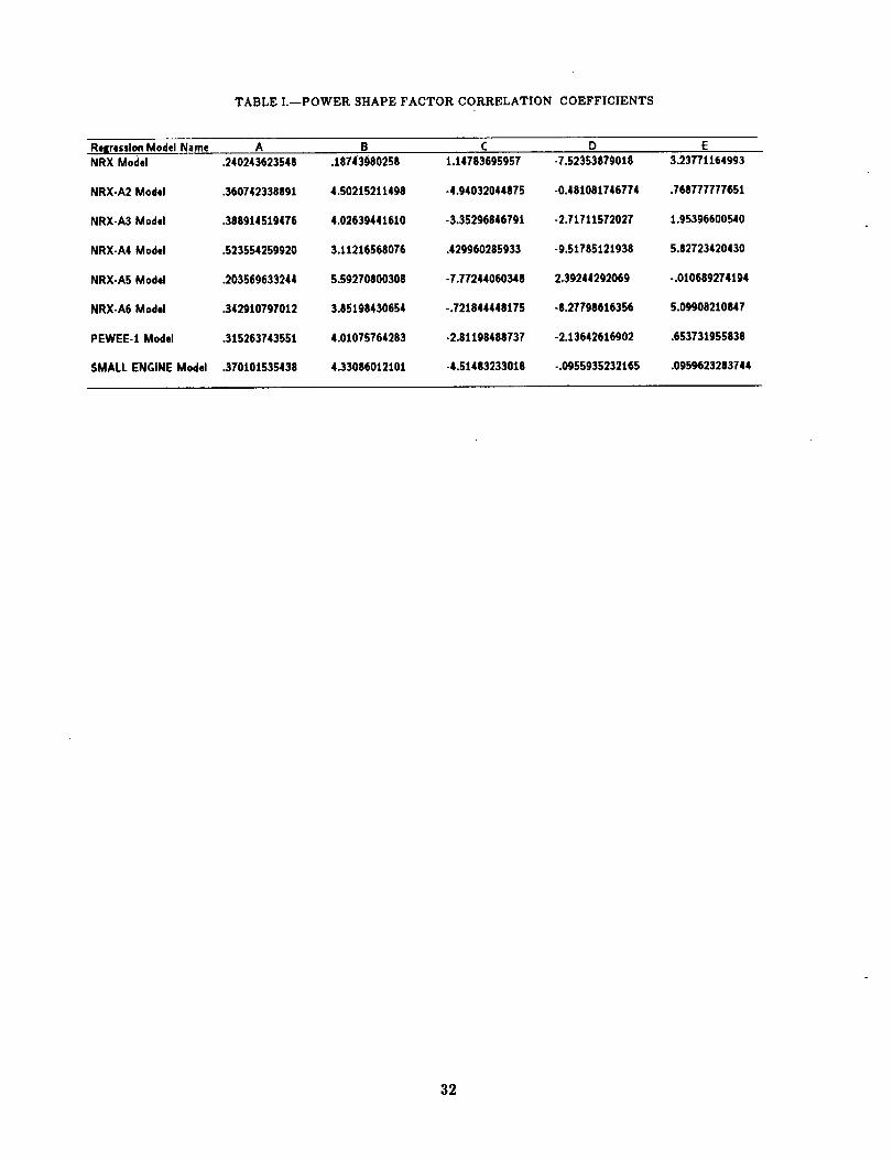
TABLE I.--POWER SHAPE FACTOR CORRELATION COEFFICIENTS
RaliressionModel Name A B C D ENRX Model .240243623548 .187430802S8 1.14783695957 -7.52353879018 3.23771164993
NRX-A2 Model .360742338891 4.50215211498 -4.94032044875 -0.481081746774 .768777777651
NRX-A3 Model .388914510476 4.02639441610 -3.35296846791 -2.7t711572027 1.95396600540
NRX.A4 Model .523554259920 3.11216568076 .429960285933 -9.51785121938 5.82723420430
NRX-A5 Model .203569633244 5.59270800308 -7.77244060348 2.39244292069 -.010689274194
NRX-A6 Model .342910797012 3.85198430654 -.721844448175 -8.27798616356 5.09908210847
PEWEE-1 Model .315263743551 4.01075764283 -2.81198488737 -2.13642616902 .653731955838
SMALL ENGINE Model .370101535438 4.33086012101 -4.51483233018 -.0955935232165 .09596232ll3744
32
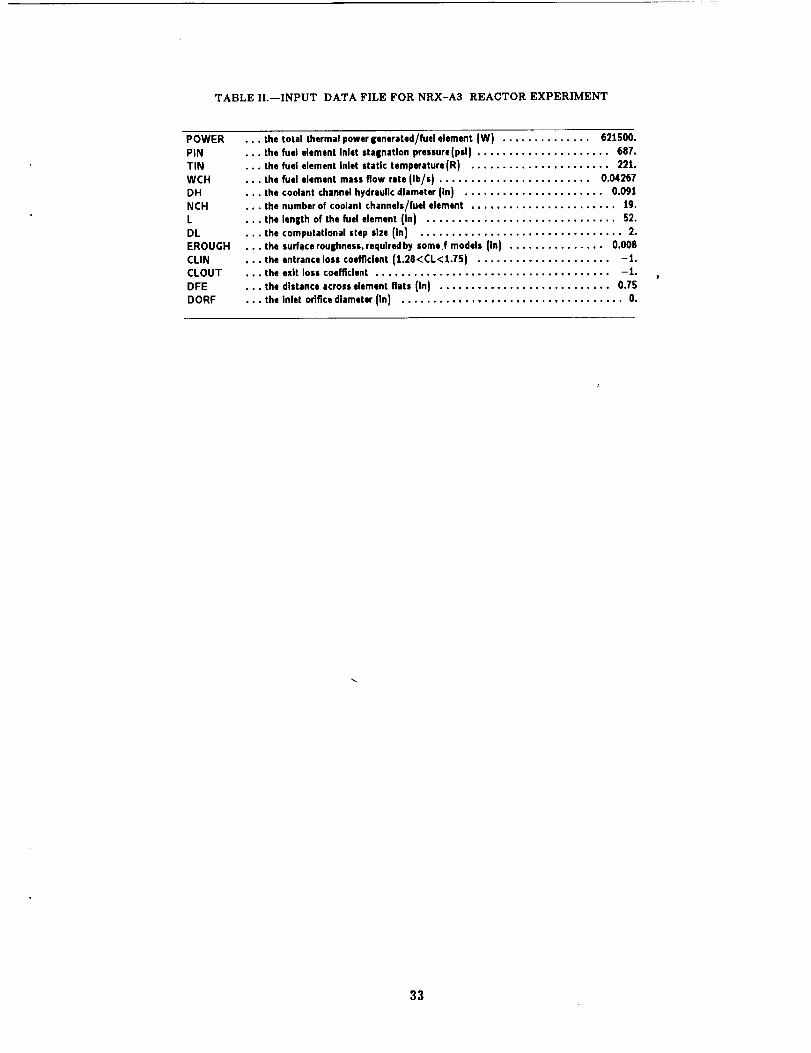
TABLE II.--INPUT DATA FILE FOR NRX-A3 REACTOR EXPERIMENT
POWER
PIN
TIN
WCH
DH
NCH
L
DL
EROUGH
CLIN
CLOUT
DFE
DORF
... the total thermal power generated/fuel element (W) .............. 621500.
•.. the fuel element Inlet stagnation pressure(pal) ..................... 687.
•.. the fuel element inlet static temperature(R) ...................... 221.
•.. the fuel element mass flow rate lib/s) ........................ 0.04267
... the coolant channel hydraulic diameter (In) ...................... 0.091
•.. the number of coolant channels/fuol element ....................... 19.
. . the length of the fuel element (in) .............................. 52.
. the computational step size (in) ................................ 2.
• the surface roughness, requlredby some f models (in) ............... 0.00S
• the entrance loss coefficient (1.28<CL<1.75) ..................... -1.
• the exit loss coefficient ..................................... -1.
• the distance across element fiats (in) ........................... 0.75
• the inlet orifice d|ameter (in) ................................... 0.
33

TABLE III.-PROGRAM ELM OUTPUT FILE FOR NRX-A3 REACTOR EXPERIMENT
PROGRAM ELM
VERSION 1.02
FEBRUARY 26, 1992
NRX-A3 EXPERIMENT CRT 21550
X (in.) Tb (R) Tw (R) Cum. P(W} Re Pb (psi) MACH00.00 0221.00 0221.00 00000.00 000000. 686.39 0.00002.00 0283.58 0670.73 00585.12 100327. 685.69 0.034
04.00 0365.16 0922.04 01351.99 085798. 685.70 0.039
06.00 0469.47 1181.51 02286.53 073070. 684.81 0,044
08.00 0597.50 1422.34 03373,76 062331. 683.40 0.050
10.00 0744.51 1635.95 04597.91 053635. 681.68 0.055
12.00 0907.27 1838.77 05942.56 0467S6. 679.63 0.06114.00 1082.71 2036_56 07300.80 041311. 677.25 0.06716.00 1268.13 2231.18 08925.28 036968. 674.51 0.07318.00 1460.66 2421.42 10528.42 033469. 671.40 0.079
20.00 1657.58 2606.67 12182.49 030623. 667.93 0.085
22.00 1856.34 2785.60 13869.76 028287. 664.09 0.091
24.00 2054.49 2956.63 15572.63 026353. 659.88 0.097
26.00 2249.76 3118.07 17273.74 024740. 655.30 0.10228.00 2440.04 3268.92 18956.13 023386. 650.36 0.108
30.00 2623.45 3408.46 20603.33 022244. 645.06 0.113
32.00 2801.57 3538.26 22199.53 021117. 639.49 0.118
34.00 2967.49 3657.16 23729.69 020261. 633.54 0.123
36.00 3123.22 3762.09 25179.63 019534. 627.27 0.128
38.00 3269.06 3851.41 26536.26 018909. 620.68 0.13240.00 3400.35 3923.59 27787.60 018376. 613.80 0.137
42.00 3517.64 3979.80 28922.98 017929. 606.66 0.141
44.00 3620.45 4021.05 29933.12 017555. 599.27 0.14646.00 3708.47 4047.58 30810.32 017245. 591.65 0.150
48.00 3781.58 4059.59 31548.52 016995. 583.83 0.154
50.00 3839.77 4057.55 32143.48 016797. 575.82 0.157
52.00 3883.21 4050.86 32592.90 016648. 563.98 0.161
619265.1 = POWER/ELEMENT
34

TABLE IV.--INPUT DATA FILE FOR NRX-A4 REACTOR EXPERIMENT
POWER
PIN
TIN
WCH
DH
NCH
L
DL
EROUGH
6CLIN
CLOUT
DFE
DORF
• • • the total thermal power generated/fuel element (W) ....... 705000.
the fuel element inlet stagnation pressure (psi) .............. 678.the fuel element inlet static temperature (R) ............... 229.
the fuel element mass flow rate (Ib/s) ................. 0.04273
the coolant channel hydraulic diameter (in) ............... 0.095
. the number of coolant channels/fuel element ............... 19.
the length of the fuel element (in) ....................... 52.
the computational step size (in) ......................... 2.
the surface roulihness, required by some f models (in) ........ 0.008
the entrance loss coefficient (1.28<CL<1.75) ............... -1.the exit loss coefficient .............................. -1.
the distance across element fiats (in) .................... 0.75
the inlet orifice diameter (in) ........................... O.
35

TABLE V.--PROGRAM ELM OUTPUT FILE FOR NRX-A4 REACTOR EXPERIMENT
PROGRAM ELMVERSION 1.02
FEBRUARY 26, 1992
NRX-A4/EST EXPERIMENT CRT 21550
X {in.} _T b [RI - Tw {R} Cum. PIW) Re Pb (p;l) MACH
00.00 0229.00 0229.00 00000.00 00000. 677.47 0.00002.00 0317.38 0912.12 00832.72 91683. 676.76 0.03304.00 0426.31 1210.86 01835.66 75491. 676.77 0.039
06.00 0561.78 1491.09 03004.21 62863. 675.87 0.04408.00 0720.39 1738.90 04329.99 53022. 674.44 0.05010.00 0898.22 1969.69 05801.30 45461. 672.71 0.05612.00 1092.08 2195.72 07403.55 39625. 670.67 0.06314,00 1299.12 2418.78 09119.69 35062. 668.30 0.06916.00 1515.99 2637.79 10930.66 31446. 665.59 0.07518.00 1739.42 285i.00 12815.82 20546. 662.54 0.081
20.00 1966.16 3056.23 14753.38 26196. 659.14 0.08722.00 2193.00 3251.26 16720.85 24273. 655.39 0.093
24.00 2416.88 3434.22 18695.48 22687. 651.31 0.09826.00 2635.02 3587.03 20654.67 21370. 646.89 0.10428.00 2848.34 3746.37 22576.44 20111. 642.21 0.10930.00 3049.62 3911.17 24439.83 19148. 637.16 0.11432.00 3240.93 4041.51 26225.37 18335. 631.81 0.11834.00 34t9.98 4152.18 27915.52 17642. 626.17 0.12336.00 3582.47 4244.44 29495.07 17058. 620.26 0.12838.00 3729.21 4320.55 30951.59 16569. 614.10 0.13340.00 3859.91 4381.75 32275.91 16159. 607.71 0.13742.00 3974.64 4433.05 33462.49 15816. 601.!0 0.141
44.00 4075.10 4474.12 34509.89 15530. 594.30 0.14546.00 4161.55 4503.58 35421.23 15292. 587.30 0.14848.00 4234.79 4526.33 36204.58 15095. 580.12 0.152S0.00 4296.44 4545.67 36873.42 14934. 572.78 0.15552.00 4348.60 4559.58 37447.08 14801. 561.58 0.158
711494.4 = POWER/ELEMENT
36
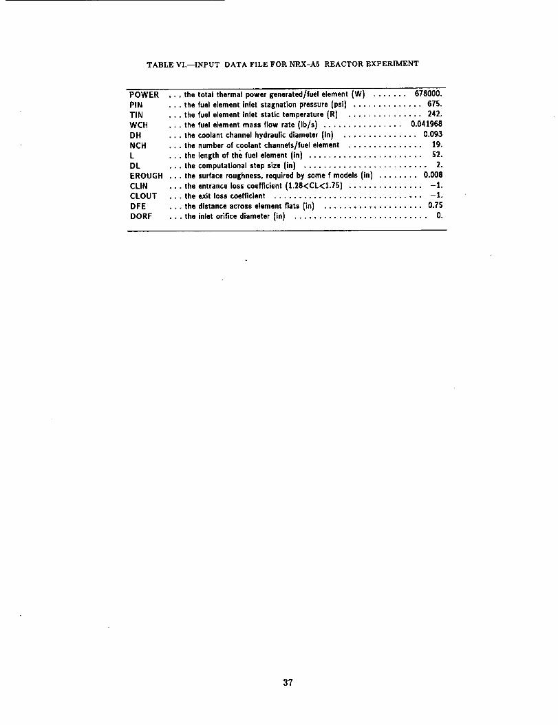
TABLE VI.--INPUT DATA FILE FOR NRX-A5 REACTOR EXPERIMENT
POWER
PIN
TIN
WCH
DH
NCH
L
DLEROUGH
CLIN
CLOUT
DFE
DORF
the total thermal power ienerated/fuel element {W) ....... 678000.
the fuel element inlet staination pressure (psi) .............. 675.
the fuel element inlet static temperature (R) ............... 242.
the fuel element mass flow rate (Ib/s) ................ 0.041968
the coolant channel hydraulic diameter (in) ............... 0.093
the number of coolant channels/fuel element ............... 19.
the length of the fuel element (in) ....................... 52.
the computational step size (in) ......................... 2.
the surface roui|hness, required by some f models (in) ........ 0.008
the entrance loss coefficient (1.28<CL<1.75) ............... -1.the exit loss coefficient .............................. -1.
the distance across element fiats (in) .................... 0.75
the inlet orifice diameter (in} ........................... O.
37

TABLE VII.--PROGRAM ELM OUTPUT FILE FOR NRX-A5 REACTOR EXPERIMENT
PROGRAM ELMVERSION 1.02
FEBRUARY 26. 1992
NRX-A _;EXPERIMENT
X (in.) Tb,R) Tw (R) Cum. P(W) Re Pb ipsi) MACHOO.00 0242.00 0242.00 00000.00 00000. 674.40 0.00002.00 0287.670597.76 oo423.08 93789. 673.83 0.03404.00 0362.02 0901.02 01110.44 82539. 673.84 0.03806.00 0466.47 1225.86 02032.18 70681. 673.07 0.04208.00 0601.45 1523.69 03159.56 59965. 671.79 0.04710.00 0760.99 1776.83 04464.92 51114. 670.19 0.05312.00 0940.37 2007.85 05921.74 44128. 668.28 0.06014.00 I136.29 2226.86 07504.63 38660. 666.02 0.06616.00 1341.96 2438,42 09189.27 34358, 663.41 0,07218.00 1556.53 2644.02 10952.51 30942. 660.45 0.07820.00 • 1775.64 2843.52 12772.28 28200, 657.12 0.08422.00 1996.21 3035.74 14627.63 25976. 653.43 0.09024.00 2215.40 3219.32 16498.73 24153. 649,38 0.09626.00 2430.69 3302.80 18366.86 22645. 644.98 0.10228.00 2639.89 3540.05 20214.41 21389. 640.22 0.10830.00 2844.50 3695.57 22024.88 20175. 635.19 0.11332.00 3037.85 3857,72 23782.89 19246. 629.77 0.11834.00 3221.77 3989.71 25474.15 18457. 624.03 0.12336.00 3395.93 4105.09 27085.49 17778. 617.96 0.12838.00 3555.47 4204.01 28604.86 17199. 611.60 0.13240.00 3701.20 4287.95 30021.29 16708. 604.95 0.13742.00 3832.61 4357.13 31324.95 16292. 598.03 0.14244.00 3949.37 4414.70 32507.07 15940. 590.86 0.14646.00 4052.09 4458.92 33560.03 15644. 583.46 0.15048.00 4140.81 4486.86 34477.29 15397. 575.83 0.154
50.00 4214.77 4500.50 35253.42 15195. 567.99 0.15852.00 4273.99 4505.38 35884.09 15034. 556.23 0.162
681797.8 = POWER/ELEMENT
38

TABLE VIII.--INPUT DATA FILE FOR NRX-A6 REACTOR EXPERIMENT
POWER
PIN
TIN
WCH
DH
NCH
L
DL
EROUGH
CLIN
CLOUT
DFE
DORF
....... the total thermal power generated/fuel element (W) ..... 710000.
............. the fuel element inlet stagnation pressure (psi) ........ 706.
............. the fuel element inlet static temperature (R) .......... 222.
........... the fuel element mass flow rate (Ib/s) ............. 0.04141
.............. the coolant channel hydraulic diameter (in) .......... 0.092
............ the number of coolant channels/fuel element ........... 19.
................. the length of the fuel element (in) ................. 52.
.............. the computational step size (in) .................... 2.
..... the surface roughness, required by some f models (in) ...... 0.008
........... the entrance loss coefficient (1.28<CL<1.75) .......... -1.
....... the exit loss coefficient ........................... -1.
............ the distance across element fiats (in) ............... 0.75
......... the inlet orifice diameter (in) ......................... O.
39

TABLE IX.--PROGRAM ELM OUTPUT FILE FOR NRX-A6 REACTOR EXPERIMENT
PROGRAM ELMVERSION 1.02
FEBRUARY 26, 1992
NRX-A6 EXPERIMENT
X (in.) Tb (R) Tw (R) Com. P(W) Re Pb (psi) MACH00.00 0222.00 0222.00 00000.00 00000. 705.49 0.00002.00 0287.86 0717.10 00598.85 94541. 704.90 0.03104.00 0376.49 1017.46 01405.44 80193. 704.90 0.03606.00 0493.3[ 1329.37 02411.07 67533. 704.13 0.04108.00 0639.13 1614.93 03603.77 56914. 702.85 0.04610.00 0808.62 1868.33 04968.63 48436. 701.28 0.05212.00 0998.33 2109.62 06488.23 41823. 699.38 0.05814.00 1204.73 2345.13 08143.03 36654. 697.16 0.06416.00 1424.11 2574.82 09911.72 32580. 694.58 0.07018.00 1652.62 2798.57 11771.61 29338. 691.65 0.07620.00 1886.55 3014.51 13699.06 26732. 688.36 0.08222.00 2122.26 3220.42 15669.82 24618. 684.71 0.08824.00 2356.27 3414.28 17659.41 22887. 680.70 0.09426.00 2585.35 3594.84 19643.55 21461. 676.35 0.09928.00 2810.11 3764,00 21598.50 20269. 671.71 0.10530.00 3022.69 3921.06 23501.45 19098. 666.71 0.10932.00 3224.59 4060.62 25330.96 18235. 661.38 0.11434.00 3414.64 4179.17 27067.25 17503. 655.74 0.11936.00 3587.31 4277.45 28692.68 16888. 649.83 0.12438.00 3743.12 4357.68 30192.06 16374. 643.66 0.12840.00 3881,51 4420.76 31553.08 15946. 637.25 0.13242.00 4002.36 4471.88 32766.69 15591. 630.62 0.13644.00 4107.47 4509.82 33827.47 15297. 623.79 0.14046.00 4195.94 4532.06 34734.01 15056. 616.78 0.14348.00 4268.57 4543.30 35489.31 14863. 609.60 0.14750.00 4326.57 4546.26 36101.18 14710. 602.28 0.15052.00 4371.59 4545.92 36582.59 14592. 591.31 0.153
695069.2 = POWER/ELEMENT
4O
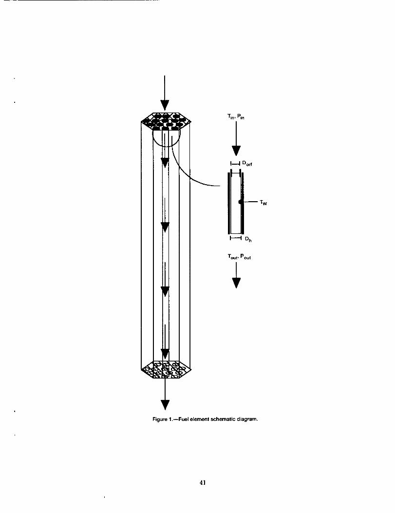
!
\
Tin, Pin
I----I Dorf
H
! _ Tw
H Dh
Tout, Pout
Figure 1.--Fuel element schematic diagram.
4]

o
g_g
1.4
1.2
1.0
.8
.6
.4
.2
0
1.4
1.2
1.0
.8
.6
.4
.2
/l
/
/l
d[
f -''=" c.
,,-- \
I iu Experimental data
•" _ Fourth-order curvefit
I I(a) NRX-A3.
\
(b) NRX-A4.
f =----_i \/
,2 .4 ,6 .8 1.0 0 .2 o4 .6
Axial position, in, Axial position, in.
(c) NRX-A5. (d) NRX-A6.
Figure 2.--Sample comparison of power shape factor curvefits to experimental data.
,8 1.0
42
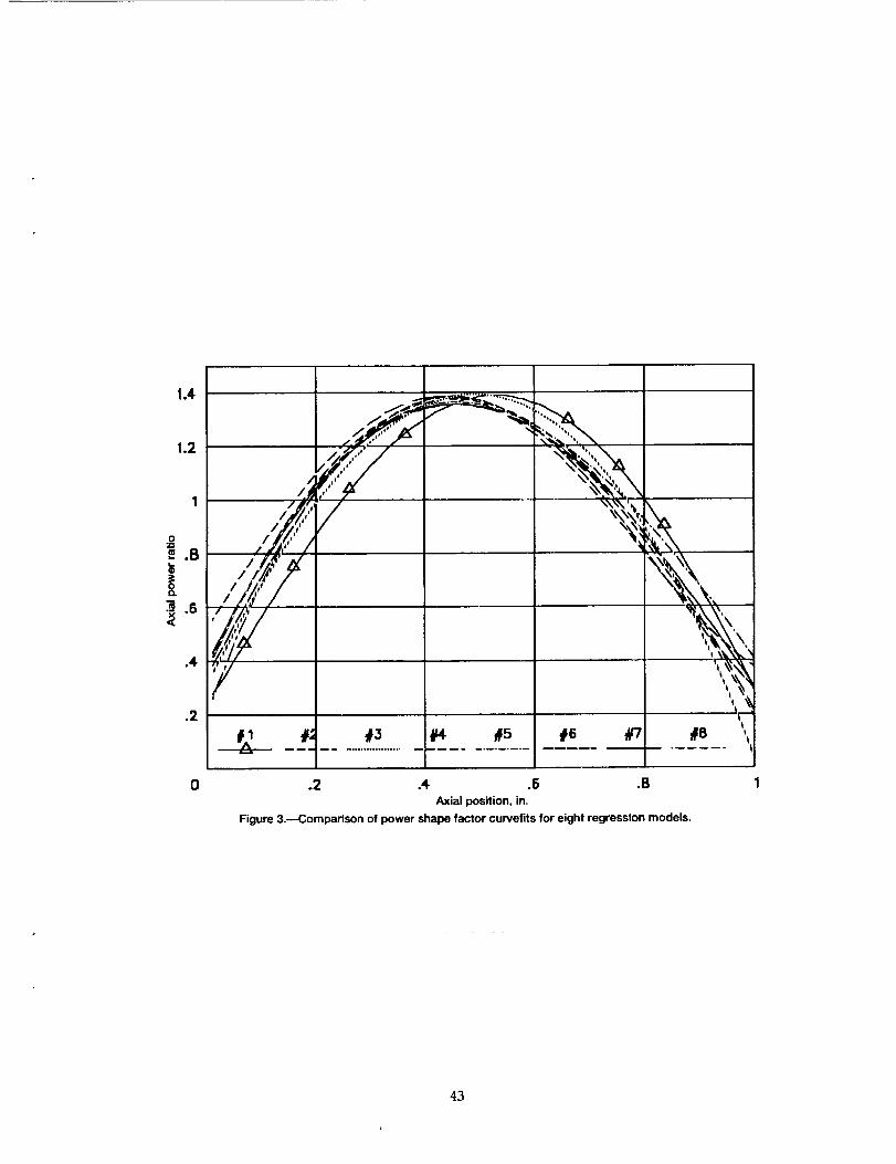
1.4
1.2
.o
_.B
.4
.2
0
,/_'_',_,
%_,\\
_5 _6 #7I
.2 .4 .6 .BAxial position, in.
Figure 3.--Comparison of power shape factor curvefits for eight regression models.
43

IExrF
PRESSURE
I IN LE
COMPUTE INLET
1PRESSURE LOSS I
I COMPUTEL.
JAXIAL_OSlTIONp
..J DETERMINE I
"lCa_S PR;PERTIESI
COMPUTE
i COMPUTEII Tout I
Figure 4._LM logic block diagram.
44
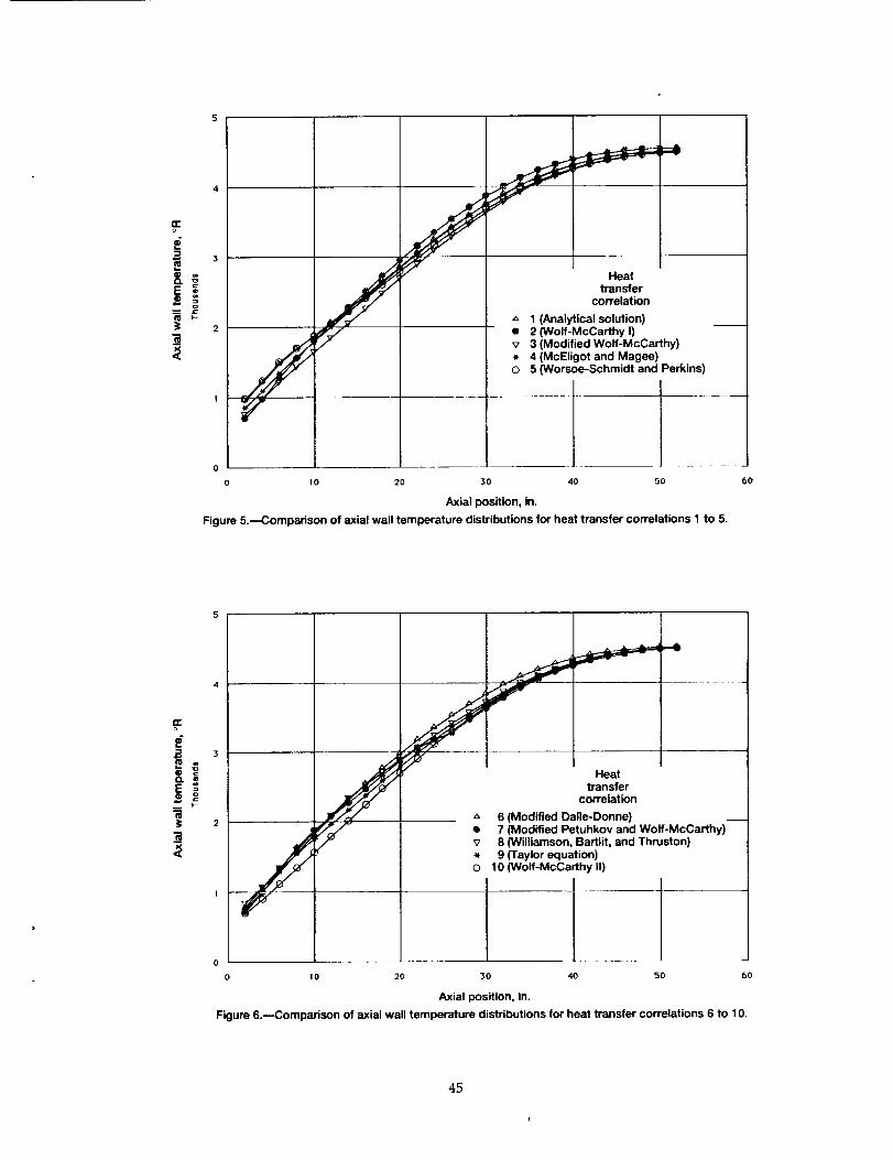
n-o
E
3
==
o
2
l
j Heat
transfer
correlation
,_ 1 (Analytical solution)
/_v/ e 2 (Wolf-McCarthy I)
j v 3 (Modified Wolf-McCarthy)
. 4 (McEligot and Magee)
O 5 (Worsoe-Schmidt and Perkins)
i
0
0 10 20 30 40 50
Axial position, in.
Figure 5._Comparison of axial wall temperature distributions for heat transfer correlations 1 to 5.
6o
F
==
op- j I
Heat
transfercorTelation
,_ 6 (Modified Dalle-Donne)
• 7 (Modified Petuhkov and Wolf-McCarthy)
_" v 8 (Williamson Bartlit, and Thruston)
• 9 (Taylor equation)O 10 (Wolf-McCarthy II)
o w0 20 30 4o 50 60
Axial position, in.
Figure 6.--Comparison of axial wall temperature distributions for heat transfer correlations 6 to 10.
45
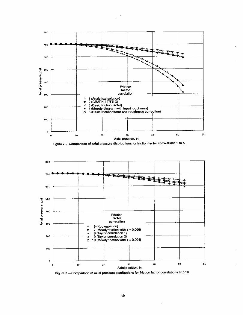
800
700
600
'_ 500C_
400
_ 300
200
100
Frictionfactor
correlation
"- t (Analytical solution)i 2 (GRAPH-I-TITE G)v 3 (Basic friction factor)* 4 (Moody diagram with input roughness)O 5 (Basic friction factor and roughness correction)
10 20 30 40 50
Axial position, in.
Figure 7.--Compadson of axial pressure distributions for friction factor correlations 1 to 5.
6O
600
700
600
-= 5oo
=w
400
¢1
3_. 300
200
100
Frictionfactor
correlation
6 (Koo equation)• 7 (Moody friction with • = 0.006)v 8 (Taylor correlation 1)• 9 (Taylor correlation 2)O 10 (Moody friction with ( = 0.004)
I0 20 30 40 50
Axial position, in.
Figure 8.--Comparison of axial pressure distributions for friction factor correlations 6 to 10.
6O
46

5x10 3 5x10 3
Increasing power _i = jf
13 43
I _ ! °hanne,_ 2 _zt" ' Power, _ 2 / , gdiamet i
_" J kW/element _ 11 Ba= _ 600
Jr --&-- 700....,..... ,8000 0
5xl 0 3 800
; i- Decreasing mass fl°w_ a_ I
" Ill I "_ 600
I ,oo
_" I t l 200_,1
I I
"i_0iiiln,diameter
i
0 10 20 30 40 50 0 10 20 30 40 50
Axial position, In.
Figure 9.--Sensitivity to changes in various input parameters.
47

F
i
5x10 3
!
/
0
5x10³
4
(a) NRX-A3.
El
4' AlP"= iJK
t'/
(b) NRX-A4.
Jf
eli'
/f
O _m
Ir
O Experimental data
.... Program ELM
.......... Te ± 1 00R
10 20 30 40 50 0 10 20 30
Axial position, in.
(c) NRX-A5. (d) NRX-A6.
Figure 10.--Comparison of program ELM to experimental data,
4O 50
48

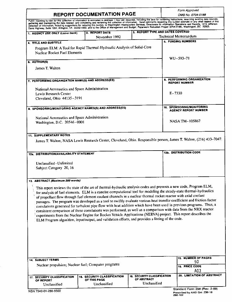
Form ApprovedREPORT DOCUMENTATION PAGE OMBNo.0704-01e8
Public reporting burden for this collection of information is estimated to average 1 hour per response, including the time for reviewing instructions, searching existing aata sources,
gathering and maintaining the data needed, and completing and reviewing the collection of information. Send comments regarding this burden estimate or any other aspect of this
collection of information, including suggestions for reducing this burden, to Washington Headquarters Services. Directorate for information Operations and Reports. 1215 Jefferson
Davis Highway, Suite 1204, Arlington, VA 22202-4302, and to the Office of Management and Budget. Paperwork Reduction Pro_ect (0704-0188), Washington. DC 20503.
1. AGENCY USE ONLY (Leave blank) J2. REPORT DATE 3. REPORT TYPE AND DATES COVERED
I November 1992 Technical Memorandum
4. TITLE AND SUBTITLE
Program ELM: A Tool for Rapid Thermal-Hydraulic Analysis of Solid-Core
Nuclear Rocket Fuel Elements
6. AUTHOR(S)
James T. Walton
7. PERFORMING ORGANIZATION NAMEiS ) AND ADDRESS(ES)
National Aeronautics and Space Administration
Lewis Research Center
Cleveland, Ohio 44135-3191
9."'SPONSORING/MONITORING AGENCY NAMESiS) AND ADDRESS(ES)
National Aeronautics and Space Administration
Washington, D.C. 20546-0001
5. FUNDING NUMBERS
WU-593-71
8. PERFORMING ORGANIZATIONREPORT NUMBER
E-7330
10. SPONSORING/MONITORINGAGENCY REPORT NUMBER
NASA TM- 105867
11. SUPPLEMENTARY NOTES
James T. Walton, NASA Lewis Research Center, Cleveland, Ohio. Responsible person, James T. Walton, (216) 433-7047.
1211. DISTRIBUTION/AVAILABILITY STATEMENT
Unclassified - Unlimited
Subject Category 20, 16
12b. DISTRIBUTION CODE
13. ABSTRACT (Maximum 200 words)
\
This report reviews the state of the art of thermal-hydraulic analysis codes and presents a new code, Program ELM,
• for analysis of fuel elements. ELM is a concise computational tool for modeling the steady-state thermal-hydraulics
of propellant flow through fuel element coolant channels in a nuclear thermal rocket reactor with axial coolant
passages. The program was developed as a tool to swiftly evaluate various heat transfer coefficient and friction factor
correlations generated for turbulent pipe flow with heat addition which have been used in previous programs. Thus, a
consistent comparison of these correlations was performed, as well as a comparison with data from the NRX reactor
"experiments from the Nuclear Engine for Rocket Vehicle Applications (NERVA) project. This report describes the
ELM Program algorithm, input/output, and validation efforts, and provides a listing of the code.
14. SUBJECT TERMS
Nuclear propulsion; Nuclear fuel; Computer programs
17. SECURITY CLASSIFICATIONOF REPORT
Unclassified
NSN 7540-01-280-5500
18. SECURITY CLASSIFICATIONOF THIS PAGE
Unclassified
19. SECURITY CLASSIFICATIONOF ABSTRACT
Unclassified
15. NUMBER OF PAGES
50'16. PRICE CODE
A0320. LIMITATION OF ABSTRACT
Standard Form 298 (Rev. 2°89)Prescribedby ANSI Std, Z39-18298-102