Embed Size (px)
Citation preview
NS-HP
RTK-Capable GNSS Receiver

NS-HP : High-Performance GNSS Receiver
• L1/B1 C/A Code
• 20 ch GPS/SBAS/QZSS + 6 ch BDS
• Sensitivity: -148dBm cold start, -160dBm tracking
• Update Rate: 2 / 4 / 5 / 8 / 10 / 20 Hz
• Position accuracy: 2.5m CEP
• Velocity accuracy: 0.1m/sec
• Timing accuracy: 10nsec
• 40mm x 38mm
• 50mA @ 3.3V

NS-HP : RTK Capable
• Support RTK base and rover modes
• 20 ch GPS/SBAS/QZSS + 6 ch BDS
• RTK position accuracy: centimeter-level
• 70mA @ 3.3V
• Update Rate 1Hz
Mode Output Output Baud Rate Input Input Baud Rate
Rover NMEA-0183 9600 ~ 115200 * RTCM-SC104 3.0, 3.1
or SkyTraq-Raw
57600
Base SkyTraq-Raw 38400 ~ 115200**
* default 115200
** when switching to base mode, need to manually change to 57600 to work with rover

NS-HP Pin-Out

Minimum Connection to Work

Potential RTK Applications
UAS Mapping
ConstructionSurveying
Agriculture
Driverless Vehicle

RTK Dynamic Performance (1/2)
Driving on inner lane making loop rounds 3 times, in 3 separate tests using 3 different antennas placed at the same
location. Each color represent result of a test with a particular antenna. Deviation less than 40cm.
Same test as previous using a popular brand normal GPS/GLONASS receiver. Deviation is larger than RTK receiver as
expected.
RTK Dynamic Performance (2/2)

Baseline vs RTK Accuracy

Precision Time & Position Stamp* (1/2)
• Input: rising edge on TRIG pin as trigger
• Output: PSTI,005 message with time and
position occurrence estimate on the trigger
• Accuracy
– Time: 100nsec
– Position: max 1msec moved distance error on top
of RTK positioning errorIf 50km/h speed � maximum 1.4cm error on top of RTK positioning error
* Available only for NS-HP-5S and -10S, 5Hz and 10Hz RTK version with precision time/position stamping

Precision Time & Position Stamp* (2/2)
• Alternative RTK, at 50Km/hr speed 10Hz RTK rate, 139cm distance moved between 2 RTK points. When movement is not constant velocity, incorrect to linear interpolate � not possible to derive precise position from time stamp
• PSTI,005 offers direct centimeter-level accuracy RTK position stamp � maximum error of 1.4cm on top of RTK’s 1cm + 1ppm error at 50Km/hr speed � far accurate than simple time stamp offered by alternative RTK solutions
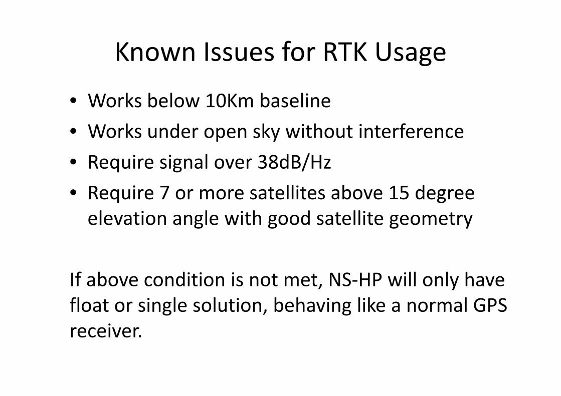
• Works below 10Km baseline
• Works under open sky without interference
• Require signal over 38dB/Hz
• Require 7 or more satellites above 15 degree
elevation angle with good satellite geometry
If above condition is not met, NS-HP will only have
float or single solution, behaving like a normal GPS
receiver.
Known Issues for RTK Usage

GPS Receiver
• Most GPS receivers use C/A code to measure
position
• A C/A code chip is roughly 300 meters
• GPS receiver can determine position with
resolution to fraction of a C/A code chip, resulting
in 2.5 meter CEP 50%* accuracy from 4 or more
GPS satellites
* 2.5m CEP 50% means 50% of the location points fall within 2.5m radius.
It is equivalent to 95% confidence level falling within 5 meter radius

GPS Receiver Error
A rectangular land with 4 corners
measured using GPS at different time on
different days. When plotted on Google
Earth, these 4 measured corners defined
rectangular lands may have area shifted
by 0 ~ +/-5 meters.
Shifted 10 meters for the worst case +5m
and -5m shifts.
This is mostly due to ionosphere and
troposphere delays.
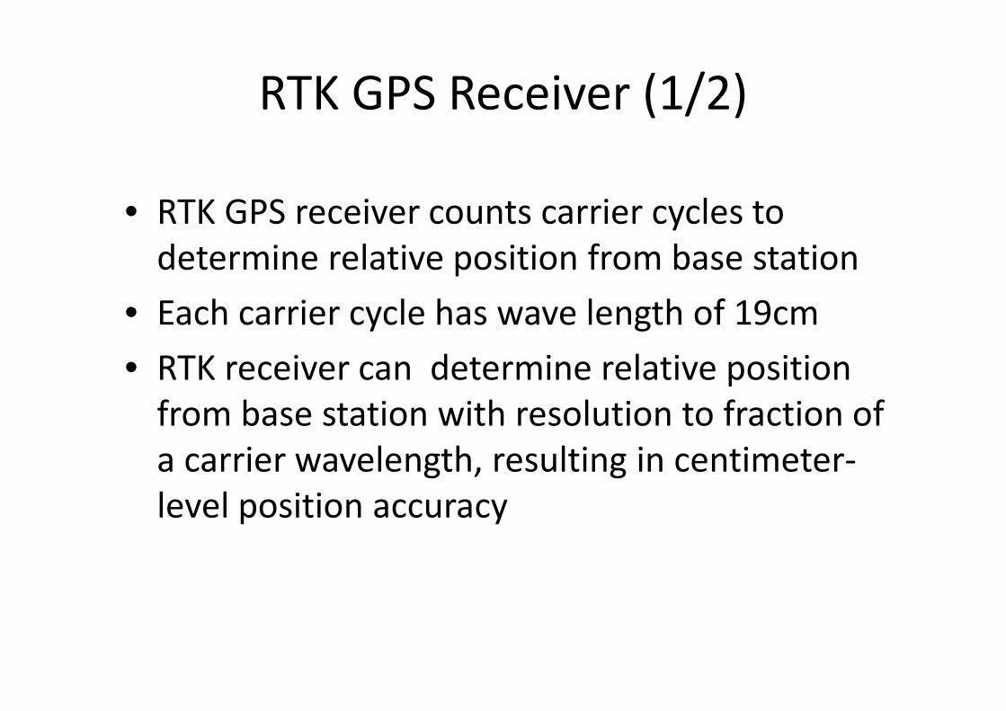
RTK GPS Receiver (1/2)
• RTK GPS receiver counts carrier cycles to
determine relative position from base station
• Each carrier cycle has wave length of 19cm
• RTK receiver can determine relative position
from base station with resolution to fraction of
a carrier wavelength, resulting in centimeter-
level position accuracy
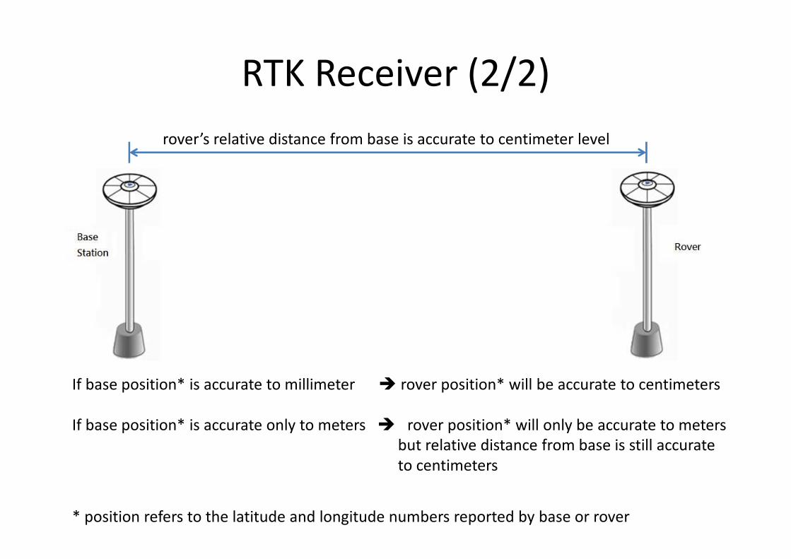
RTK Receiver (2/2)
rover’s relative distance from base is accurate to centimeter level
If base position* is accurate to millimeter � rover position* will be accurate to centimeters
If base position* is accurate only to meters � rover position* will only be accurate to meters
but relative distance from base is still accurate
to centimeters
* position refers to the latitude and longitude numbers reported by base or rover

Usage Configuration 1 1/3
using
NS-HP as rover
NTRIP
Client
RTCM
3.x
cm-level accuracy
NMEA output

Usage Configuration 1 2/3
Can use two UART-to-USB adapter for connecting to PC for Internet connection and
seeing result.

Usage Configuration 1 3/3
Upgrade your smartphone GPS to RTK precision
1. Have Internet-connected Android smartphone
2. Use a Bluetooth Serial module (2.1 EDR) connecting to NS-HP
UART1 TX1 and UART2 RX2
3. Set smartphone Developer Options to allow mock locations
enabling use of external GPS
4. Run NTRIP client software (Lefebure) on the smartphone to
stream base station data to NS-HP, retrieve NMEA from NS-HP to
make high-precision RTK position available for other Android
applications

Usage Configuration 2 1/4
using
NS-HP as rover
wireless
receiver
cm-level accuracy
relative to base
NMEA
output
using
NS-HP
as base station
carrier phase raw
measurement
wireless
transmitter
carrier phase raw
measurement

Usage Configuration 2 2/4
• If a known surveyed point exists with
centimeter position accuracy, placing base
station NS-HP antenna there, and enter the
location coordinates into NS-HP, then the
rover NMEA output will have cm-level position
accuracy.

RTK Usage Configuration 2 3/4
• If no known surveyed point exists, place the base station NS-HP antenna at some fixed location that is to be later used as reference point.
• After base station NS-HP self-surveyed, take note of the latitude/longitude location reported, to be entered as base station location for future use; also mark the physical location of the reference point for future use.
• Using this method, the rectangular land defined by 4 corners measured by normal GPS receiver that we shown earlier, if measured using RTK receiver over many different days, will only have area shifted in centimeters on Google Earth, not 10 meter!

Usage Configuration 2 4/4
base station location
(X, Y) (X + 3315.78λ, Y )
(X, Y+2052.63λ ) (X + 3315.78λ, Y+2052.63λ )
With base set at a fixed location, the RTK rover determines the other three corner locations as
#1: 3315.78 wavelength to the right
#2: 2052.63 wavelength to the north
#3: 3315.78 wavelength to the right and 2052.63 wavelength to the north
Once base (X,Y) is given a fixed coordinate, when RTK rover measures the other 3 corner
coordinates at different days, the results will only differ by fractional wavelength, yielding
centimeter-level accuracy relative to the base.
With this kind of rover-to-base relative positioning application, once base is set at a fixed
location, accuracy of the (X,Y) coordinate that we measured, meter or centimeter, is not
important, so long as the same (X,Y) coordinate number is used for base location, and base
antenna is placed at same location afterwards when using rover to measure position.
For short baseline open-sky relative positioning
application, lower-cost single-frequency RTK receiver
could be used, a considerable cost saving from
alternative multi-frequency RTK receivers.
#1
#2 #3
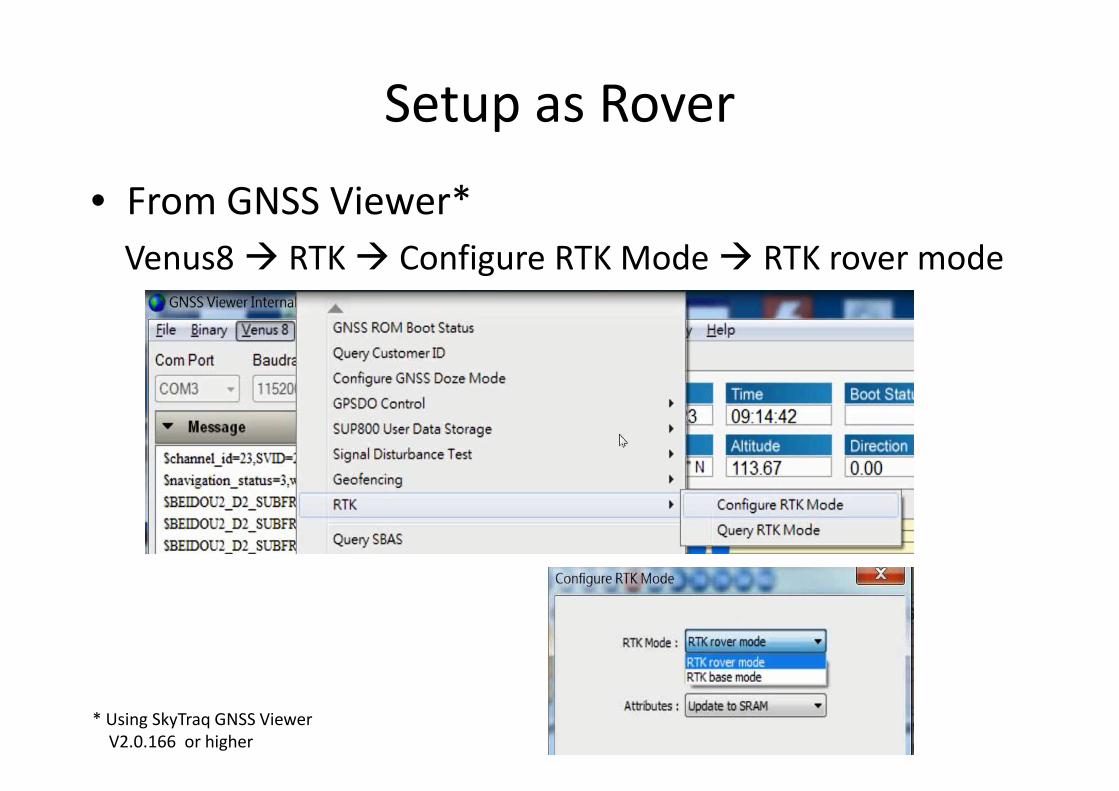
Setup as Rover
• From GNSS Viewer*
Venus8 � RTK � Configure RTK Mode � RTK rover mode
* Using SkyTraq GNSS Viewer
V2.0.166 or higher
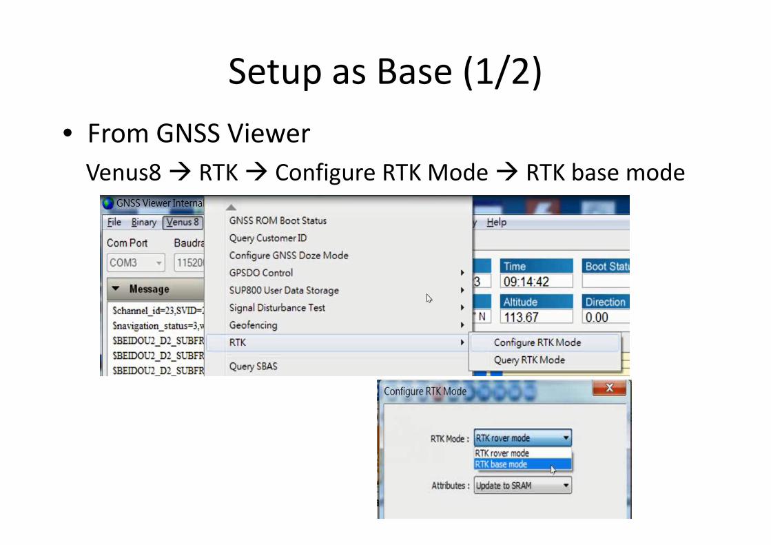
Setup as Base (1/2)
• From GNSS Viewer
Venus8 � RTK � Configure RTK Mode � RTK base mode

Setup as Base (2/2)
• From GNSS Viewer
1PPS Timing � Configure Timing � Static (input base position)

Application Example 1
• Precision Machine Control
Once coordinates of the polygon corners are determined by the rover, precision steering of machine can be controlled by the autopilot software using the cm-level accuracy position provided by the RTK rover

Application Example 2
• Precision Aerial Imaging
– RTK rover equipped UAV can take photo at predefined
locations, centimeter-level exact, resulting in images that
are always taken at the right spot, always consistent.
– Acquire same amount of image data when flying against
or with the wind.
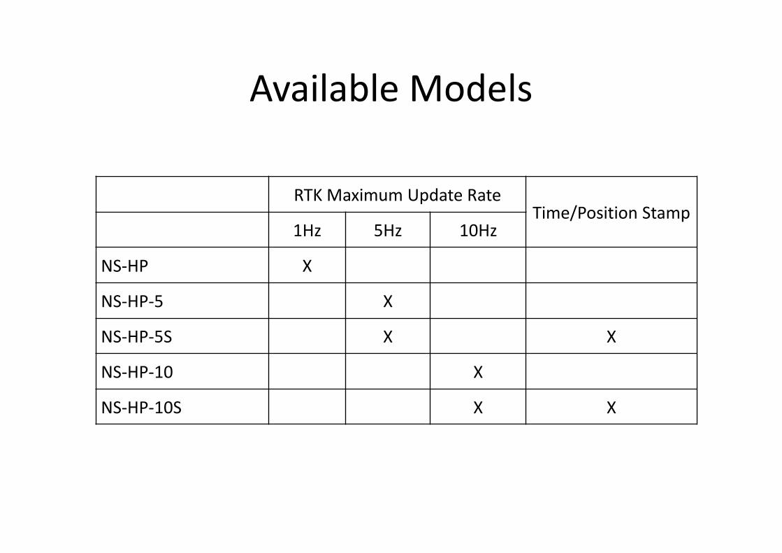
Available Models
RTK Maximum Update RateTime/Position Stamp
1Hz 5Hz 10Hz
NS-HP X
NS-HP-5 X
NS-HP-5S X X
NS-HP-10 X
NS-HP-10S X X

NS-HP
Affordable RTK Capable GNSS Receiver