Embed Size (px)
Citation preview
NRAO CHEMICAL LAB REPORT NO. 1
PROCESS NOTES ON ELECTROPLATING
John Lichtenberger
Several aspects of electroplating presently used at NRAO differ from standard industrial practice. This paper describes these as well as the chemistry and control of standard procedures.
Metals which can be electroplated from aqueous (water) solutions of their salts lie, with a few exceptions, in the center portion of the periodic table and correspond to the transition metal series. Those plated at NRAO include gold, silver, copper, nickel and chromium. Gold, silver and copper exhibit desirable properties for microwave use, while nickel and chromium are both corrosion resistant and durable.
No single electroplating bath can produce all the desired properties for a given metal. Bath chemistry controls the deposit characteristics and must be considered for a given application. For example, while cyanide copper plating baths produce the best adhesion on metal substrates, acid copper baths produce more ductile copper, and deposits are more suitable for electroforming applications.
Section I. Bath Chemistry, Make-Up, and Control
The electroplating baths used in the Chemistry Lab are divided into three categories:
1. acid, or low pH baths 2. neutral baths 3. alkaline, or high pH baths
The acid baths in use include chromium plating from chromic acid, gold plating from the ACR C-27 bath, nickel plating from Sel-Rex Lectro-Nic 10-03 process, and copper plating and electroforming from Sel-Rex CuBath #1 sulfuric acid process. The chromium plating bath is made up for use only when required from the following chemicals: chromic acid, technical grade; sulfuric acid, technical grade. The bath composition, given in "Modern Electroplating", 3rd Edition, pp.95, is
chromic acid (Cr03) ~ 250 gms/liter
sulfate (S0^=) as H^SO^ - 2.5 gms/liter
This bath is operated at temperatures from 400C up to 550C, depending on the rate of deposition required. At 40oC, the current density for pro¬ ducing bright chrome plate must be between 3.1 and 15.5 A/dm^.
-2-
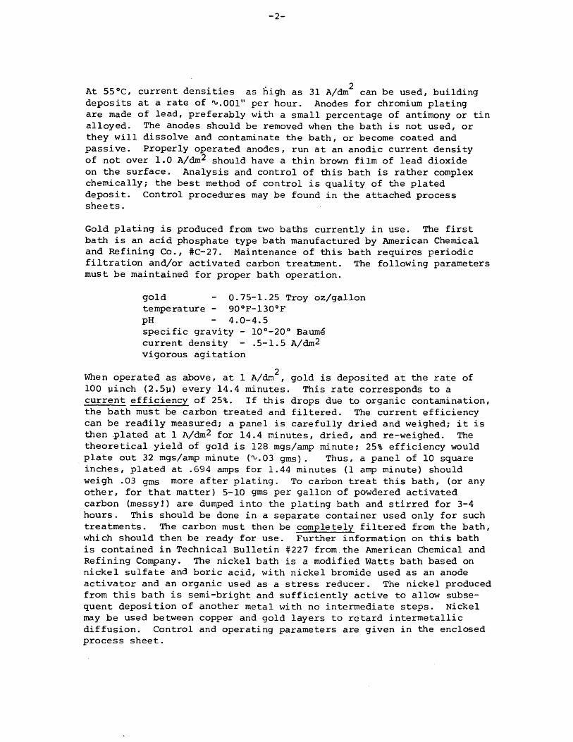
. . • 2 At 550C, current densities as high as 31 A/dm can be used, building deposits at a rate of 'v.OOl" per hour. Anodes for chromium plating are made of lead, preferably with a small percentage of antimony or tin alloyed. The anodes should be removed when the bath is not used, or they will dissolve and contaminate the bath, or become coated and passive. Properly operated anodes, run at an anodic current density of not over 1.0 A/dm^ should have a thin brown film of lead dioxide on the surface. Analysis and control of this bath is rather complex chemically; the best method of control is quality of the plated deposit. Control procedures may be found in the attached process sheets.
Gold plating is produced from two baths currently in use. The first bath is an acid phosphate type bath manufactured by American Chemical and Refining Co., #C-27. Maintenance of this bath requires periodic filtration and/or activated carbon treatment. The following parameters must be maintained for proper bath operation.
gold - 0.75-1.25 Troy oz/gallon temperature - 90oF-130oF pH - 4.0-4.5 specific gravity - 10o-20o Baume current density - .5-1.5 A/dm2 vigorous agitation
2 When operated as above, at 1 A/dm , gold is deposited at the rate of 100 yinch (2.5y) every 14.4 minutes. This rate corresponds to a current efficiency of 25%. If this drops due to organic contamination, the bath must be carbon treated and filtered. The current efficiency can be readily measured; a panel is carefully dried and weighed; it is then plated at 1 A/dm^ for 14.4 minutes, dried, and re-weighed. The theoretical yield of gold is 128 mgs/amp minute; 25% efficiency would plate out 32 mgs/amp minute (^.03 gms). Thus, a panel of 10 square inches, plated at .694 amps for 1.44 minutes (1 anp minute) should weigh .03 gms more after plating. To carbon treat this bath, (or any other, for that matter) 5-10 gms per gallon of powdered activated carbon (messy!) are dumped into the plating bath and stirred for 3-4 hours. This should be done in a separate container used only for such treatments. The carbon must then be completely filtered from the bath, which should then be ready for use. Further information on this bath is contained in Technical Bulletin #227 from.the American Chemical and Refining Company. The nickel bath is a modified Watts bath based on nickel sulfate and boric acid, with nickel bromide used as an anode activator and an organic used as a stress reducer. The nickel produced from this bath is semi-bright and sufficiently active to allow subse¬ quent deposition of another metal with no intermediate steps. Nickel may be used between copper and gold layers to retard intermetallic diffusion. Control and operating parameters are given in the enclosed process sheet.
-3-
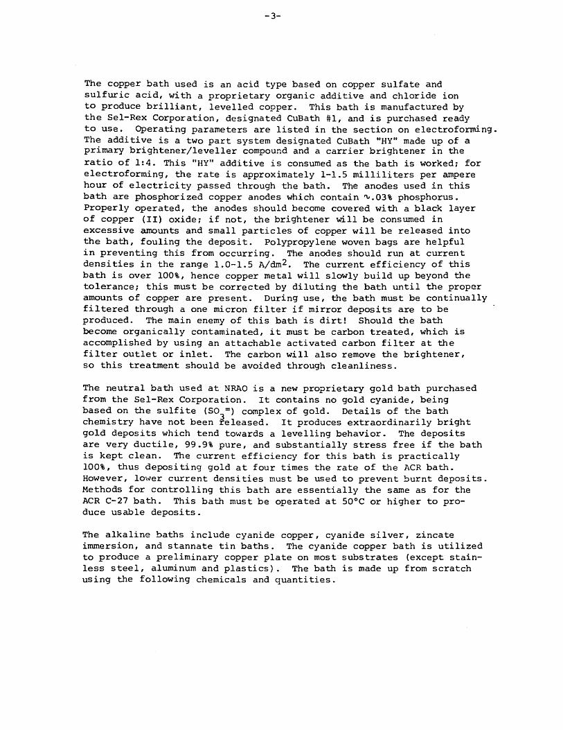
The copper bath used is an acid type based on copper sulfate and sulfuric acid, with a proprietary organic additive and chloride ion to produce brilliant, levelled copper. This bath is manufactured by the Sel-Rex Corporation, designated CuBath #1, and is purchased ready to use. Operating parameters are listed in the section on electroforming. The additive is a two part system designated CuBath "HY" made up of a primary brightener/leveller compound and a carrier brightener in the ratio of 1:4. This "HY" additive is consumed as the bath is worked; for electroforming, the rate is approximately 1-1.5 milliliters per ampere hour of electricity passed through the bath. The anodes used in this bath are phosphorized copper anodes which contain ^.03% phosphorus. Properly operated, the anodes should become covered with a black layer of copper (II) oxide; if not, the brightener will be consumed in excessive amounts and small particles of copper will be released into the bath, fouling the deposit. Polypropylene woven bags are helpful in preventing this from occurring. The anodes should run at current densities in the range 1.0-1.5 A/dm^. The current efficiency of this bath is over 100%, hence copper metal will slowly build up beyond the tolerance; this must be corrected by diluting the bath until the proper amounts of copper are present. During use, the bath must be continually filtered through a one micron filter if mirror deposits are to be produced. The main enemy of this bath is dirt! Should the bath become organically contaminated, it must be carbon treated, which is accomplished by using an attachable activated carbon filter at the filter outlet or inlet. The carbon will also remove the brightener, so this treatment should be avoided through cleanliness.
The neutral bath used at NRAO is a new proprietary gold bath purchased from the Sel-Rex Corporation. It contains no gold cyanide, being based on the sulfite (SO^-) complex of gold. Details of the bath chemistry have not been released. It produces extraordinarily bright gold deposits which tend towards a levelling behavior. The deposits are very ductile, 99.9% pure, and substantially stress free if the bath is kept clean. The current efficiency for this bath is practically 100%, thus depositing gold at four times the rate of the ACR bath. However, lower current densities must be used to prevent burnt deposits. Methods for controlling this bath are essentially the same as for the ACR C-27 bath. This bath must be operated at 50oC or higher to pro¬ duce usable deposits.
The alkaline baths include cyanide copper, cyanide silver, zincate immersion, and stannate tin baths. The cyanide copper bath is utilized to produce a preliminary copper plate on most substrates (except stain¬ less steel, aluminum and plastics). The bath is made up from scratch using the following chemicals and quantities.
-4-
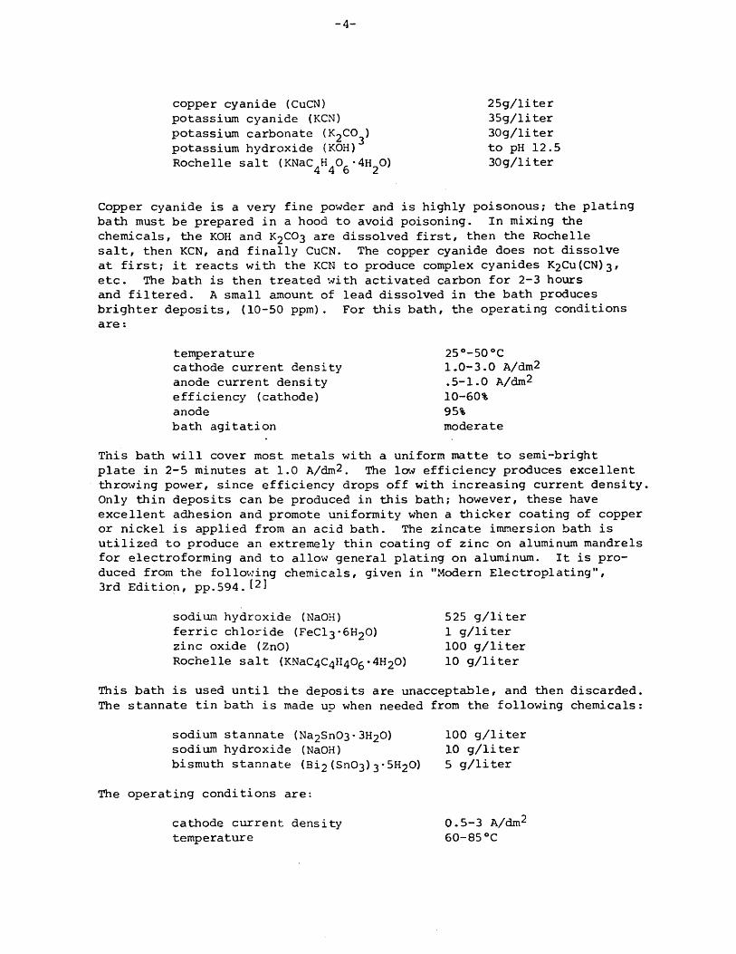
copper cyanide (CuCN) potassium cyanide (KCN) potassium carbonate (I^CO^) potassium hydroxide (KOH) Roche lie salt (KNaC^C^ • 4^0)
25g/liter 35g/liter 30g/liter to pH 12.5 30g/liter
Copper cyanide is a very fine powder and is highly poisonous; the plating bath must be prepared in a hood to avoid poisoning. In mixing the chemicals, the KOH and K2CO3 are dissolved first, then the Rochelle salt, then KCN, and finally CuCN. The copper cyanide does not dissolve at first; it reacts with the KCN to produce complex cyanides K2Cu(CN)3, etc. The bath is then treated with activated carbon for 2-3 hours and filtered. A small amount of lead dissolved in the bath produces brighter deposits, (10-50 ppm). For this bath, the operating conditions are:
This bath will cover most metals with a uniform matte to semi-bright plate in 2-5 minutes at 1.0 A/dm2. The low efficiency produces excellent throwing power, since efficiency drops off with increasing current density. Only thin deposits can be produced in this bath; however, these have excellent adhesion and promote uniformity when a thicker coating of copper or nickel is applied from an acid bath. The zincate immersion bath is utilized to produce an extremely thin coating of zinc on aluminum mandrels for electroforming and to allow general plating on aluminum. It is pro¬ duced from the following chemicals, given in "Modern Electroplating", 3rd Edition, pp.594,
This bath is used until the deposits are unacceptable, and then discarded. The stannate tin bath is made up when needed from the following chemicals:
temperature cathode current density anode current density efficiency (cathode) anode bath agitation
25o-50 0C 1.0-3.0 A/dm2 .5-1.0 A/dm2
10-60% 95% moderate
sodium hydroxide (NaOH) ferric chloride (FeC^-SI^O) zinc oxide (ZnO) Rochelle salt (KNaC^^^O^• 4H2O)
525 g/liter 1 g/liter 100 g/liter 10 g/liter
sodium stannate (Na2Sn03•3H2O) sodium hydroxide (NaOH) bismuth stannate (Bi2 (Sn03) 3* 5^0)
100 g/liter 10 g/liter 5 g/liter
The operating conditions are:
cathode current density temperature
0.5-3 A/dm2
60-850C
-5-
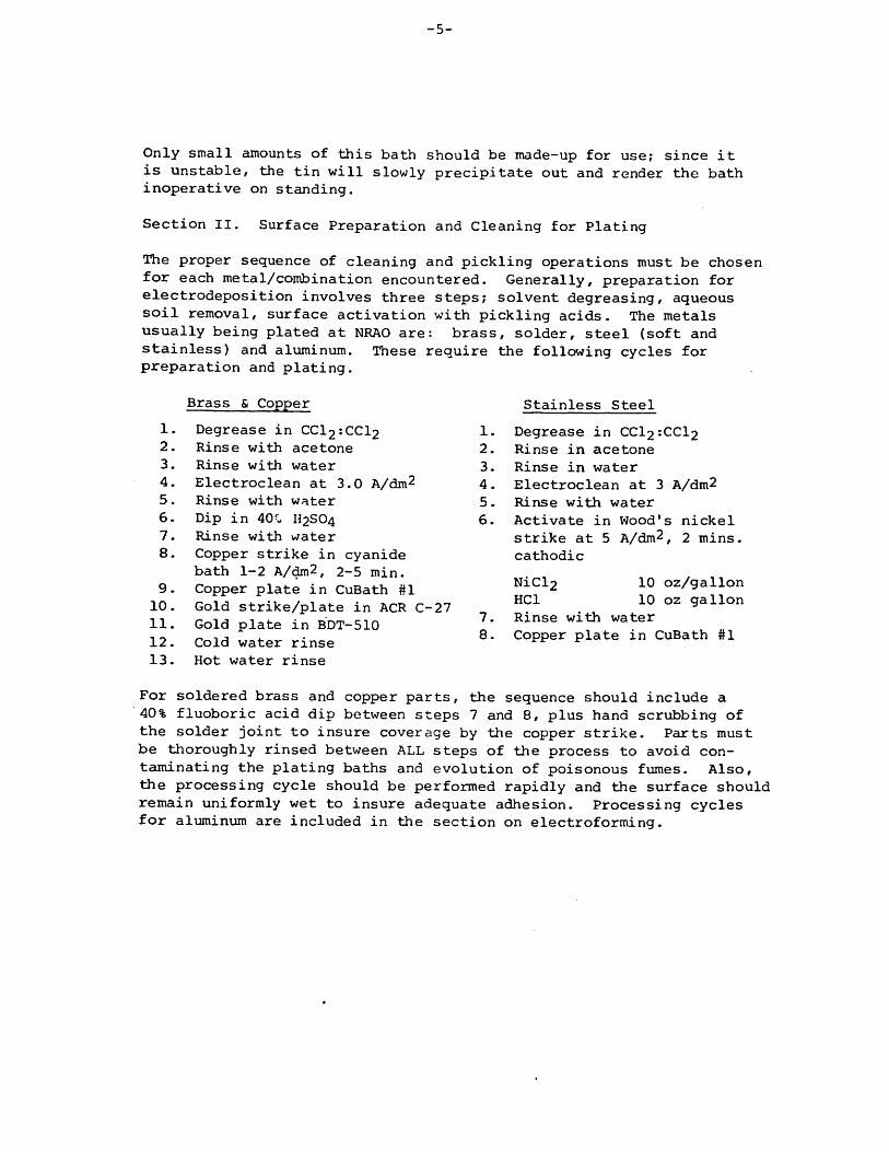
Only small amounts of this bath should be made-up for use; since it is unstable, the tin will slowly precipitate out and render the bath inoperative on standing.
Section II. Surface Preparation and Cleaning for Plating
The proper sequence of cleaning and pickling operations must be chosen for each metal/combination encountered. Generally, preparation for electrodeposition involves three steps? solvent degreasing, aqueous soil removal, surface activation with pickling acids. The metals usually being plated at NRAO are: brass, solder, steel (soft and stainless) and aluminum. These require the following cycles for preparation and plating.
Brass & Copper
1. Degrease in CCl2:CCl2 2. Rinse with acetone 3. Rinse with water 4. Electroclean at 3.0 A/dm^ 5. Rinse with water 6. Dip in 40H2SO4 7. Rinse with water 8. Copper strike in cyanide
bath 1-2 A/dm2/ 2-5 min. 9. Copper plate in CuBath #1
10. Gold strike/plate in ACR C-27 11. Gold plate in BDT-510 12. Cold water rinse 13. Hot water rinse
Stainless Steel
1. Degrease in CCl2:CCl2 2. Rinse in acetone 3. Rinse in water 4. Electroclean at 3 A/dm2 5. Rinse with water 6. Activate in Wood's nickel
strike at 5 A/dm^, 2 mins. cathodic
NiCl2 10 oz/gallon HC1 10 oz gallon
7. Rinse with water 8. Copper plate in CuBath #1
For soldered brass and copper parts, the sequence should include a 40% fluoboric acid dip between steps 7 and 8, plus hand scrubbing of the solder joint to insure coverage by the copper strike. Parts must be thoroughly rinsed between ALL steps of the process to avoid con¬ taminating the plating baths and evolution of poisonous fumes. Also, the processing cycle should be performed rapidly and the surface should remain uniformly wet to insure adequate adhesion. Processing cycles for aluminum are included in the section on electroforming.
-6-
Section III. Electroforming for Microwave Component Fabrication
Electroforming involves the preparation of a suitable mandrel for deposition, utilization of the proper plating bath, and subsequent removal of the mandrel. Aluminum mandrels used at NRAO are prepared as follows:
1) Ultrasonic degrease in perchlorethylene 10-15 minutes
2) Rinse in CH^OH (methanol)
3) Soak clean in tri-sodium phosphate 20 gms/liter, 1-3 minutes at 70oC
4) Rinse in distilled water
5) Dip in 5% hydrofluoric acid, 15 seconds or until aluminum gases uniformly (CAUTION! Highly Corrosive Acid!)
6) Rinse in distilled water
7) Apply zinc film from zincate immersion bath 10-15 seconds with agitation
8) Dissolve film in 40% nitric acid
9) Repeat step 7
10) Rinse in distilled water
11) Quickly immerse in copper-cyanide strike bath at 2.6 amperes/ decimeter^ for 2 minutes (POISONOUS!)
12) Rinse in distilled water
13) Gold plate if necessary
14) Place in electroforming bath
After step 3, the surface of the mandrel should be uniformly wet, having no water-breaks, or the subsequent copper strike will not adhere to the mandrel. Before placing the zincated surface into the cyanide strike, electrical contact should be made to the part, or the zinc will dissolve before it is covered with copper. Do not allow the zinc film to dry! Caution is the word since this process involves highly poisonous compounds. Thorough rinsing between steps is essential for successful work and safety to the operator.
The plating bath used for electroforming is CuBath #1 copper plating process purchased from the Sel-Rex Corporation 13]. it utilizes a proprietary additive to produce levelling brilliant copper. The cyanide strike is a low cyanide formulation found in most reference books on plating, as is the zincate plating bath^l.
-7-
To produce a sound electroform many bath parameters must be controlled, the best results being obtained under the following conditions:
Copper sulfate - 9 oz./gallon
Sulfuric acid - 25 oz./gallon
C1 (chloride) - 60 mg./liter (ppm)
Temperature - 70oF (210C)
Current density - 2.5-3.5 amps/dm^
CuBath "HY" additive - 1.0-1.5 mis/amp-hour
Continuous filtration, vigorous agitation with oil-free air
Under these conditions, copper is deposited at a rate of one mil (.001") every 36 minutes (at 3.2 amps/dm^) or roughly .04" per day. If current interruption occurs, the mandrel must be removed from the bath and electro-polished in 85% orthophosphoric acid at 14-18 amps/dm^. This procedure removes a passive film which forms on the copper in the absence of electric currently]. jf this is omitted, the subsequent copper layers will not adhere when the deposit is machined.
On complex shapes, auxiliary anodes may be required to further direct the electric field (and the deposit) into recesses and grooves. These may be fabricated from stainless steel or titanium, and should follow the contour of the mandrel as closely as possible. Acrylic plastic may be used to fabricate shields to insulate a portion of the mandrel from the bath or to direct the electric field to another section of the mandrel requiring greater deposit thickness. These shields and anodes must be placed empirically, as it is difficult to predict their effects even on simple shapes from theory. Methods employed for removing the mandrel after electroforming involve dissolution of the aluminum in either concentrated hydrochloric acid or sodium hydroxide (cheaper, but takes longer and is more messy). Both solutions are used near boiling and do not attack the copper. After the aluminum has been dissolved, the thin layer of copper remaining is removed to expose the interior gold plate by dipping in ferric chloride solution, being careful not to undercut the gold.
FOOTNOTES
^Frederick A. Lowenheim, ed., "Modern Electroplating"/ 3rd Edition, New York, 1974, pp.96-98•
^Ibid, pp. 594
[3] Sel-Rex Corporation, "CuBath #1 Acid Copper Plating Process", Nutley, New Jersey 07110.
[41 Metals and Plastics Publications Inc., "Metal Finishing Guidebook and Directory", 42nd Edition, Westwood, New Jersey, 1974, pp.497-498.
[5] Frederick A. Lowenheim, ed., "Modern Electroplating", 3rd Edition, New York, 1974, pp.582.
BIBLIOGRAPHY
^Same as 1 above
[2] Metals and Plastics publications Inc., "Metal Finishing Guidebook
and Directory", 42nd Edition, Westwood, N.J., 1974.
[3] E.I. DuPont De Nemours & Co., Inc., Plating Product Bulletins #50 and #41.
[41 American Chemical & Refining Co., Inc., Technical Bulletin #227.
^The Sel-Rex Company, Sel-Rex "Lectro-Nic 10-03 Nickel Plating Process", Technical Bulletin and "BDT 510 Gold Plating Process" Technical Bulletin.
Technical Bulletin No. 227 Page I of k {72-kO)
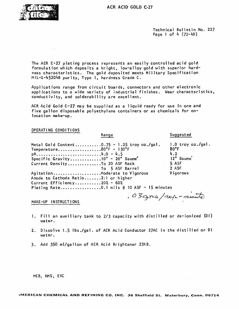
The ACR C-27 plating process represents an easily controlled acid gold formulation which deposits a bright, low-alloy gold with superior hard¬ ness characteristics. The gold deposited meets Military Specification MIL-G-^520^B purity, Type 1, hardness Grade C.
Applications range from circuit boards, connectors and other electronic applications to a wide variety of industrial finishes. Wear characteristics, conductivity, and solderabi1ity are excellent.
ACR Acid Gold C-27 ray be supplied as a 1iquid ready for use in one and five gallon disposable polyethylene containers or as chemicals for on- 1 ocation make-up.
OPERATING CONDITIONS Range Suggested
Metal Gold Content 0.75 - 1.25 troy oz./gal . 1.0 troy oz./gal . Temperature 80oF - 130oF 80oF pH k.O - k.5 k .2 Specific Gravity 10° - 20° Baume' 12° Baume' Current Density To 20 ASF Rack 5 ASF
To 5 ASF Barrel 2 ASF Agitation Moderate to Vigorous Vigorous Anode to Cathode Ratio 2:1 or higher Current Efficiency .....20% - 60% Plating Rate 0.1 mils @ 10 ASF - 15 minutes
MAKE-UP INSTRUCTIONS
1. Fill an auxiliary tank to 2/3 capacity with distilled or de-ionized (Dl) water.
2. Dissolve 1.5 lbs./gal. of ACR Acid Conductor 27AC in the distilled or Dl water.
3. Add 350 ml/gallon of ACR Acid Brightener 27AB.
MEB, HMS, EKC
AMERICAN CHEMICAL AND REFINING CO. INC. 36 Sheffield St. Waterbury, Conn. 06714
Technical Bulletin No. 227 Page 2 of k {72-kd)
ACR Acid Gold C-27
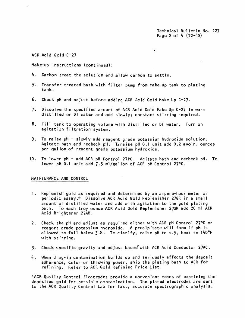
Make-up Instructions (continued):
k. Carbon treat the solution and allow carbon to settle.
5. Transfer treated bath with filter pump from make up tank to plating tank.
6. Check pH and adjust before adding ACR Acid Gold Make Up C-27.
7. Dissolve the specified amount of ACR Acid Gold Make Up C-27 in warm distilled or Dl water and add slowly; constant stirring required.
8. Fill tank to operating volume with distilled or Dl water. Turn on agitation filtration system.
9. To raise pH - slowly add reagent grade potassium hydroxide solution. Agitate bath and recheck pH. "braise pH 0.1 unit add 0.2 avoir, ounces per gallon of reagent grade potassium hydroxide.
10. To lower pH - add ACR pH Control 27PC. Agitate bath and recheck pH. To lower pH 0.1 unit add 7.5 ml/gallon of ACR pH Control 27PC.
MAINTENANCE AND CONTROL
1. Replenish gold as required and determined by an ampere-hour meter or periodic assay.- Dissolve ACR Acid Gold Replenisher 27GR in a small amount of distilled water and add with agitation to the gold plating bath. To each troy ounce ACR Acid Gold Replenisher 27GR add 20 ml ACR Acid Brightener 27AB.
2. Check the pH and adjust as required either with ACR pH Control 27PC or reagent grade potassium hydroxide. A precipitate will form if pH is allowed to fall below 3.8. To clarify, raise pH to 4.5, heat to l40oF with stirring.
3. Check specific gravity and adjust baume^with ACR Acid Conductor 27AC.
k. When drag-in contamination builds up and seriously affects the deposit adherence, color or throwing power, ship the plating bath to ACR for refining. Refer to ACR Gold Refining Price List.
"ACR Quality Control Electrodes provide a convenient means of examining the deposited gold for possible contamination. The plated electrodes are sent to the ACR Quality Control Lab for fast, accurate spectrographic analysis.
fhe Sel-Rex Company
OPERATSNG
PRECIOUS METAL DIVISION
u
BDT! 510
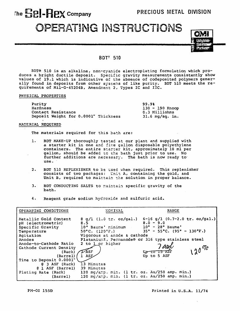
BDT® 510 is an alkaline, non-cyanide electroplating formulation which pro¬ duces a bright ductile deposit. Specific gravity measurements consistently show values of 19.1 which is indicative of the absence of codeposited polymers gener¬ ally found in deposits from other syscens of like purity. BDT 510 meets the re¬ quirements of Mil-G-45204B, Amendnent 2, Types IC and IIC.
99.9% 130 - 190 Knoop 0.3 Milliohms 31.6 mg/sq. in.
PHYSICAL PROPERTIES
Purity Hardness Contact Resistance Deposit Weight for 0.0001" Thickness
MATERIAL REQUIRED
The materials required for this bath are:
1. BDT MAKE-UP thoroughly tested at our plant and supplied with a starter kit in one and five gallon disposable polyethylene containers. The entire star-er kit, approximately 10 ml per gallon, should be added -c rhe bath just prior to use. No further additions are necessary. The bath is now ready tc use.
2. BDT 510 REPLENISHER to be used when required. This replenisher consists of two packages: Unit A, containing the gold, and Unit B, required to maintain -he solution in proper balance.
3. BDT CONDUCTING SALTS to maintain specific gravity of the bath.
4. Reagent grade sodium hydroxide and sulfuric acid.
OPERATING CONDITIONS
Metallic Gold Content pH (electrometric) Specific Gravity Temperature Agitation Anodes Anode-to-Cathode Ratio Cathode Current Density
(Rack) (Barrel)
Time to Deposit 0.0001" @ 3 ASF (Rack)
@ 1 ASF (Barrel) Plating Rate (Rack)
(Barrel)
NOMINAL
8 g/1 (1.0 tr. oz/gal.) 8.5 10° Baur.e' r.inimum 50oC. (12 0 cr.)
RANGE
6-16 g/1 (0.7-2.0 tr. oz/gal.) 8.0 - 9.0 10° - 28° Baume* 35° - 55#C. (95° - 130oF.)
Vigorous at anode & cathode Plataniu--x, Permanode® or 316 type stainless steel 2 to 1 or higher
7
13 Minutes 39 Minutes 120 mg/ar.p . 120 mc/arp.
mr.. rr. in.
(1 tr. (1 tr.
qa-to 15 KSF Up to 5 ASF
oz. Au/250 amp, oz. Au/250 amp,
Vc
min.) min.)
PM-OI 155D Printed in U.S.A. 11/74
PROCESS MAINTENANCE
Metal Content; The metallic gold content of the bath should be controlled between 6 to 16 grams per liter (0.7 and 2.0 troy ounces per gallon). To repla the materials that are consumed during electrolysis, regular additions of BDT 5 replenisher A and B should be made to the bath. Replenisher A material is sup¬ plied in liquid form in a polyethylene container. Unit B, also a liquid, is si plied in a screw-cap polyethylene container.
Standard containers of 1, 2, and 10 troy ounces (as metal), simplify repl« ishment of gold. Replenisher solutions A and B are added with stirring to the electrolyte. Analytical determination of gold in the electrolyte, followed by necessary additions of BDT 510 replenisher, will maintain the plating solution the proper concentration levels.
pH Control; The pH of the bath should be maintained between pH 8.0 and 9 electrometric. This is accomplished through the use of 5% Sulfuric Acid solut: to lower the pH or a solution of 20% sodium hydroxide to increase the pH.
# Conductivity; In order to maintain the conductivity of the bath, BDT 510
Conducting Salts are supplied. Conducting salts should be added to the bath t< prevent it from falling below 10° Baume'.
When the bath reaches a Baume* of 28°, it becomes necessary to either rep the bath with a new solution, or regenerate the bath by dilution methods. The local Technical Service Representative should be contacted for guidelines in n generating a BDT 510 bath.
CONTROL OF IMPURITIES
Metallic Impurities: Introduction of metallic impurities into the bath should be prevented by proper rinsing of the parts to be plated and the use of a Sel~Rex Aurobond© APS strike prior to gold plating.
Organic Impurities: Bulletin PM-TA 101A entitled "Carbon Treatment of Precious and Non-Precious Metal Plating Solutions" is available upon request f your Technical Service Representative.
All recommendations and suggestions appearing in this bulletin concerning the use of our products are based upon tests and data believed to be reliable. Since the actual use by others is beyond our control, no guarantee, express or implied, is made by The Sel-Rex Company as to the. effects of such use or the results to be obtained, nor is any information to be construed as a recommendation to infringe any patent. The Sel-Rex Company assumes no liability for incidental, consequential or direct damages of any kind, no matter vhat the cause, including negligence.
OFFICES: 3628 E. Olympic Boulevard, Los Angeles, CA 90023 • (213) 262-4101 5400 McDermott Drive, Berkeley. IL 60163 • (312) 449-8510 2679 Peachtree Square, Atlanta, Ga. 30340 • (404) 458-9101 5160 West 164th Street, Cleveland, OH 44142 • (216) 267-2320 21441 Hoover Road, Warren, Ml 48089 • (313) 539-3400 105 Bellows Street, Warwick, Rl 02888 • (401) 781-0700
SOLD AND SERVICED IN CANADA BY: Oxy Metal Finishing of Canada. Ltd. 165 Rexdale Boulevard, Rexdale, Ontario • (416) 743-8815
THE Rex COMP*
75 River Ro»d-Null»y, N«w 07110-(20t) 6*7 OXY METAL INDUSTRIES CORPORA!
Udyue Stf Rn I 0> -00«l» C»tUiC*l co»»o«
The SbI-Rex Company
OPERATING INSTRUCTIONS
SEL REX CUBATH' PROCESS NO. 1
I. INTRODUCTION
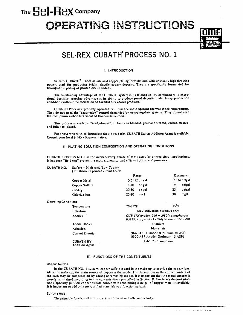
Sel-Rex CUBATH* Processes are acid copper plating formulations, with unusually high throwing power, used for producing bright, ductile copper deposits. They are specifically formulated for through-hole plating of printed circuit boards.
The outstanding advantage of the CUBATH system is its leveling ability combined with excep¬ tional ductility. Another advantage is its ability to produce sound deposits under heavy production conditions without the formation of harmful breakdown products.
CUBATH Processes, properly operated, will pass the most rigorous thermal shock requirements. They do not need the "razor-edge" control demanded by pyrophosphare systems. They do not need the continuous carbon treatment of flouborate systems.
This process is available "ready-to-use". It has been blended, peroxide treated, carbon treated, and fully test plated.
For those who wish to formulate their own baths. CUBATH Starter Addition Agent is available. Consult your local Sel-Rex Representative.
II. PLATING SOLUTION COMPOSITION AND OPERATING CONDITIONS
CUBATH PROCESS NO. 1 is the overwhelming choice of most users for printed circuit applications. It has been "field-test" proven the most economical and efficient of the acid processes.
CUBATH NO. 1 Sulfate - High Acid/Low Copper (1:1 throw in printed circuit holes*
Copper Metal Copper Sulfate H2S04 Chloride Ion
Operating Conditions Temperature Filtration Anodes
Anode Hooks Agitation Current Density
CUBATH HY Addition Agent
Rang* 2-2 1/2 oz cal 8-10 oz gal
20-30 oz gal 20-80 mg I
Optimum 2 1/4 oz/gal 9 oz/gal
23 oz/gal 30 mg/l
70-85oF 750F for clarification purposes only
CUBATH anodes .040 — .OfiO^ phosphorous (OFHC copper or electrolytic cannot be used)
titanium blower air
20-40 ASF Cathode (Optimum 30 ASF) 10-20 ASF Anode tOptimum 15 ASF)
1 4-1 2 ml'amp hour
III. FUNCTIONS OF THE CONSTITUENTS
Copper Sulfata In the CUBATH NO. 1 system, copper sulfate is used in the make-up to provide the copper ions.
After the make-up, the main source of copper is the anode. The fluctuations in the copper content of the bath may be compensated by adding or removing anodes. It is important that the metal content is closely maintained according to the concentrations prescribed in Section 11. For heavy dragout situa¬ tions, specially purified copper sulfate concentrate (containing 8 oz cal of copper metal) is available. It is important to add only pre-purified materials to a functioning bath.
Sulfuric Acid The principle function of sulfuric acid is to maintain bath conductivity.
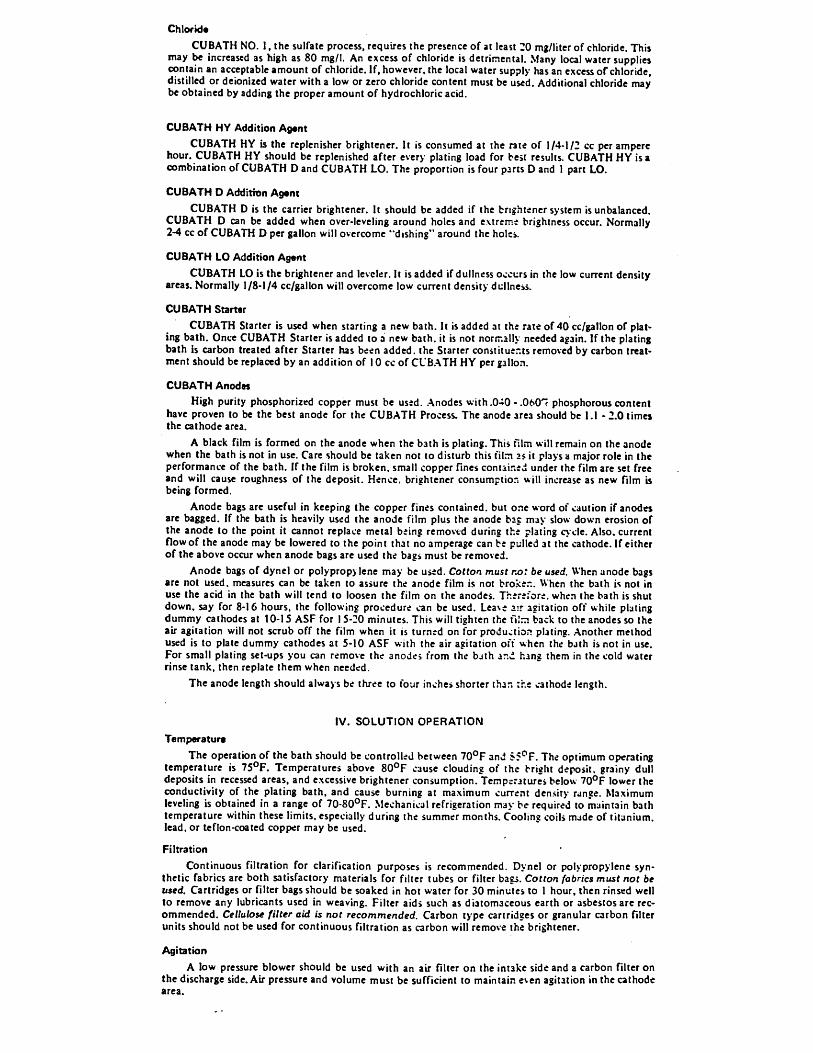
Chlortd* CUBATH NO. 1, the sulfatc process, requires the presence of at least TO mg/Hter of chloride. This
may be increased as high as 80 mg/I. An excess of chloride is detrimental. Many local water supplies contain an acceptable amount of chloride. If, however, the local water supply has an excess of chloride, distilled or deionized water with a low or zero chloride content must be used. Additional chloride may be obtained by adding the proper amount of hydrochloric acid.
CUBATH HY Addition Ag«nt CUBATH HY is the replenisher brightener. It is consumed at the rate of 1/4-1/2 cc per ampere
hour. CUBATH HY should be replenished after every plating load for best results. CUBATH HY is a combination of CUBATH D and CUBATH LO. The proportion is four parts D and I part LO.
CUBATH D Addition Agent CUBATH D is the carrier brightener. It should be added if the brightener system is unbalanced.
CUBATH D can be added when over-leveling around holes and extreme brightness occur. Normally 2-4 cc of CUBATH D per gallon will overcome "dishing" around the holes.
CUBATH LO Addition Agent CUBATH LO is the brightener and leveler. It is added if dullness occurs in the low current density
areas. Normally 1/8-1/4 cc/gallon will overcome low current density dullness.
CUBATH Starter CUBATH Starter is used when starting a new bath. It is added at the rate of 40 cc/gallon of plat¬
ing bath. Once CUBATH Starter is added to a new bath, it is not normally needed again. If the plating bath is carbon treated after Starter has been added, the Starter constituents removed by carbon treat¬ ment should be replaced by an addition of 10 cc of CL'BATH HY per gallon.
CUBATH Anodes High purity phosphorized copper must be used. Anodes with .O-iO - .OfrCr phosphorous content
have proven to be the best anode for the CUBATH Process. The anode area should be I.I - 2.0 times the cathode area.
A black film is formed on the anode when the bath is plating. This film will remain on the anode when the bath is not in use. Care should be taken not to disturb this film 25 it plays a major role in the performance of the bath. If the film is broken, small copper fines containeu under the film are set free and will cause roughness of the deposit. Hence, brightener consumption will increase as new film is being formed.
Anode bags are useful in keeping the copper fines contained, but one word of caution if anodes are bagged. If the bath is heavily used the anode film plus the anode bsc may slow down erosion of the anode to the point it cannot replace metal being removed during the plating cycle. Also, current flow of the anode may be lowered to the point that no amperage can be pulled at the cathode. If either of the above occur when anode bags are used the bags must be removed.
Anode bags of dynel or polypropylene may be used. Cotton must no: be used. When anode bags are not used, measures can be taken to assure the anode film is not broken. When the bath is not in use the acid in the bath will tend to loosen the film on the anodes. Therefore, when the bath is shut down, say for 8-16 hours, the following procedure can be used. Leave air agitation off while plating dummy cathodes at 10-15 ASF for 15-20 minutes. This will tighten the film back to the anodes so the air agitation will not scrub off the film when it is turned on for production plating. Another method used is to plate dummy cathodes at 5-10 ASF with the air agitation off when the bjth is not in use. For small plating set-ups you can remove the anodes from the bath ani hang them in the cold water rinse tank, then replate them when needed.
The anode length should always be three to four inches shorter than :he cathode length.
IV. SOLUTION OPERATION Temperature
The operation of the bath should be controlled between 70oF and Sf^F. The optimum operating temperature is 750F. Temperatures above 80oF cause clouding of the bright deposit, grainy dull deposits in recessed areas, and excessive brightener consumption. Temptratures below 70oF lower the conductivity of the plating bath, and cause burning at maximum current density range. Maximum leveling is obtained in a range of 70-80oF. Mechanical refrigeration may be required to maintain bath temperature within these limits, especially during the summer months. Cooling coils made of titanium, lead, or teflon-coated copper may be used.
Filtration Continuous filtration for clarification purposes is recommended. Dynel or polypropylene syn¬
thetic fabrics are both satisfactory materials for filter tubes or filter bags. Cotfon fabrics must not be used. Cartridges or filter bags should be soaked in hot water for 30 minutes to 1 hour, then rinsed well to remove any lubricants used in weaving. Filter aids such as diatomaceous earth or asbestos are rec¬ ommended. Cellulose filter aid is not recommended. Carbon type cartridges or granular carbon filter units should not be used for continuous filtration as carbon will remove the brightener.
Agitation A low pressure blower should be used with an air filter on the intake side and a carbon filter on
the discharge side. Air pressure and volume must be sufficient to maintain even agitation in the cathode area.
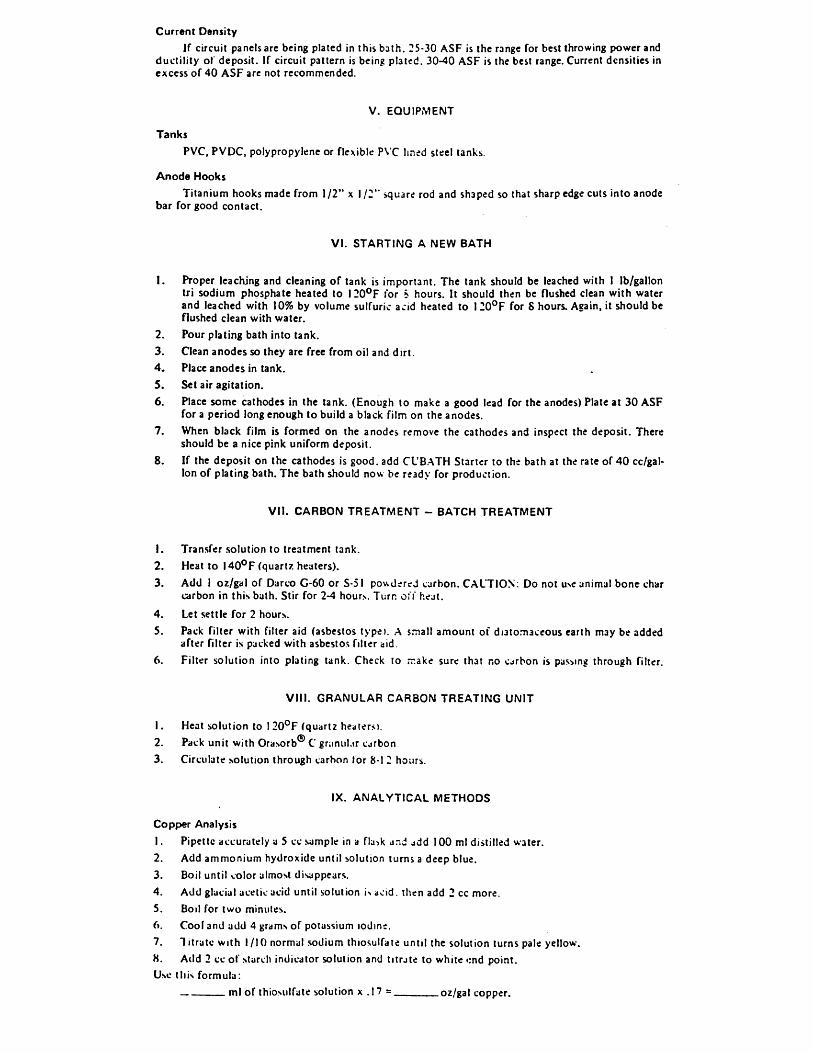
Current Dsnsity If circuit panels arc being plated in this bath. 25-30 ASF is the range for best throwing power and
ductility of deposit. If circuit pattern is being plated. 30-40 ASF is the best range. Current densities in excess of 40 ASF are not recommended.
V. EQUIPMENT
Tanks PVC, PVDC, polypropylene or flexible PVC lined steel tanks.
Anode Hooks Titanium hooks made from 1/2" x 1/2" square rod and shaped so that sharp edge cuts into anode
bar for good contact.
VI. STARTING A NEW BATH
1. Proper leaching and cleaning of tank is important. The tank should be leached with I lb/gallon tri sodium phosphate heated to 120oF for S hours. It should then be flushed clean with water and leached with 10% by volume sulfuric acid heated to 120oF for 8 hours. Again, it should be flushed clean with water.
2. Pour plating bath into tank. 3. Clean anodes so they are free from oil and dirt. 4. Place anodes in tank. 5. Set air agitation. 6. Place some cathodes in the tank. (Enough to make a good lead for the anodes) Plate at 30 ASF
for a period long enough to build a black film on the anodes. 7. When black film is formed on the anodes remove the cathodes and inspect the deposit. There
should be a nice pink uniform deposit. 8. If the deposit on the cathodes is good, add CUBATH Starter to the bath at the rate of 40 cc/gal-
lon of plating bath. The bath should now be ready for production.
VII. CARBON TREATMENT - BATCH TREATMENT
1. Transfer solution to treatment tank. 2. Heat to l40oF (quartz heaters). 3. Add 1 oz/gal of Darco G-60 or S-51 powderej carbon. CAlTlON: Do not u>e animal bone char
carbon in this bath. Stir for 2-4 hour>. Turn oi l" heat.
4. Let settle for 2 hours. 5. Pack filter with filter aid (asbestos type). A small amount of diatomaceous earth may be added
after filter is packed with asbestos filter aid. 6. Filter solution into plating tank. Check to rrake sure that no carbon is passing through filter.
VIII. GRANULAR CARBON TREATING UNIT
1. Heat solution to I 20oF (quartz heaters). 2. Pack unit with Orasorb® C gnmul.tr carbon 3. Circulate solution through carbon for 8-1 2 hours.
IX. ANALYTICAL METHODS
Copper Analysis 1. Pipette accurately a 5 cc sample in a flask and ddd 100 ml distilled water. 2. Add ammonium hydroxide until solution turns a deep blue. 3. Boil until color almost disappears. 4. Add glacial acetic acid until solution is acid, then add 2 cc more. 5. Boil for two minutes. 6. Cool and add 4 grams of potassium iodine. 7. 1 itrate with I/I0 normal sodium thiosulfate until the solution turns pale yellow. 8. Add 2 cc of starch indicator solution and titrate to white <:nd point. Use this formula: ml of thiosulfate solution x . I 7 = oz/gal copper.
1. Pipette 5 ml of copper sulfate solution into a 250ml Ehrlenmeyer flask.
2. Add I SO ml distilled water and 5 drops of 0.2^ Methyl orange solution.
3. Titrate with standard 1.0 N sodium hydroxide (NaOH) solution until the color changes from violet to pule green.
Use this formula:
ml of 1.0 N NaOH x 1.31 = oz/gal sulfuric add.
Chloride Analysis
1. Add 5.0 ml of concentrated nitric acid, reagent grade, to a 25 ml glass stoppered graduated cyl¬ inder lE.H. Sargent #24745.)
2. Add with a pipette 5.0 ml of the acid copper solution and mix.
3. Add 10.0 ml of ethylene glycol, reagent grade. Dilute to 24.0 ml with distilled water. Stopper the cylinder and mix thoroughly.
4. Add 1.0 ml of 0.10 N silver nitrate solution. Stopper and mix immediately.
5. Prepare a reference solution by repeating the above procedure except dilute this solution to 25.0 ml in Step #3 and omit Step #4. Mix thoroughly.
ft. Allow these two solutions to stand at room temperature for 30 minutes ± 1.0 minute.
7. Measure the absorbance of the solution prepared in Step -4 using the solution prepared in Step #5 as reference solution, with a Beckman "DL*" Spectrophotometer, equipped with l.Ocmpy- rex absorption cells at a wavelength of 440.0 milli-microns.
8. Chloride ion concentration of the acid copper solution in mg I = 152.0 x A44Q
where A44Q = absorbance measured in Step ^7
X. RATE OF DEPOSITION FROM ACID COPPER SOLUTION
THICKNESS IN INCHES
Amps/sq. ft. .0001 .0002 .0003 .0004 .0005 .001
T t M E
I N
M I N U T E S
10 10.8 22 33 42.1 53.2 107
20 5.4 10.8 17 21.2 27 54
30 3.6 7.2 10.8 14.1 18.2 36
40 2.7 5.4 8.1 10.7 13.1 26
50 1.9 3.6 5.4 7.2 8.9 18.5
80 1.4 2.6 4.1 5.4 6.8 13.5
All recommendations and suggestions appearing in this bulletin concerning the use of our products are based upon tests and data believed to be reliable. Since the actual use by others is beyond our coritrol, no guarantee, express or implied, is made by The Sel-Rex Company as to the effects of such use or the results to be obtained, nor is any infornation to be construed as a recommendation to infringe any patent. The Sel-Rex Cor.par.y assumes no liability for incidental, consequential or direct damages of any kind, no matter vhat the cause, including negligence.
ES: 3628 E. Olympic Boulevard, Los Angeles, Calif. 90023 • (213)262-4101 5400 McDermott Drive, Berkeley, III. 60163 • (312) 449-8510 -rur- H u r. „ a 2679 Peachtree Square, Atlanta, Ga. 30340 • (404) 458-9101 THE SH1 3 m a~a SH1 a COM 5160 West 164th Street, Cleveland, Ohio 44142 • (216) 267-2320 21441 Hoover Road, Warren, Mich. 48089 • (313) 539-3400 75 River Road • Nuilvy, New J#r»«y 07110 • (201)
.m R.|*0f®88 * (401) 781-0700 OXY METAL FINTSHING CORPOR/ IN CANADA BY: Oxy Metal Finishing of Canada, Ltd. Udyine-Sei-Ri 165 Rexdale Boulevard, Rexdale, Ontario • (416) 743-8815
OPERATING INSTRUCTIONS
SEL-REX LECTRO-NIC" 10 03
NICKEL PLATING PROCESS
INTRODUCTION
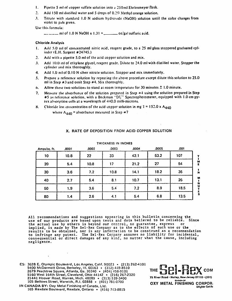
Lectro-Nic 10-03 is a modified watts type nickel electro plating formu¬ lation that produces slightly tensile stressed semi-bright, ductile nickel deposits that are ideally suited as an undercoat for precious or non- precious metal deposits. The process is designed primarily for use on printed circuits, connectors, semi-conductor devices and other high relia¬ bility electronic piece parts. Lectro-Nic 10-03 deposits conform to Federal Specification QQN-290, Class 2, Amendment 1.
PLATING SOLUTION COMPOSITION AND
OPERATION CONDITIONS
The process is shipped ready to use in liquid form in either 5 gallon Cubitainers or 15 gallon non-returnable drums. No carbon treatment or low current density dummying is required prior to putting the Lectronic 10-03 nickel process into service.
Operating conditions are as follows:
Range Opti mum
Ni ckel (as metal) 7.5-TOoz ./gal . 9 .Ooz./gal.
Nickel Sulfate 32-44oz ./gal . 40oz./gal.
Boric Acid 4-6oz./gal . 5.4oz ./gal .
Anode Activator 180-320cc/gal . 240cc/gal .
pH 2.5-4.0 3.0
Temperature . 1 2 5-1 35° F . 130° F.
Current Densi ty 15-80 ASF 40 ASF
Stress Reducer 2-6 g./gal . 4 g./gal.
PC MC-01 105D Printed in U.S.A. 573
CHEMICAL CONTROL
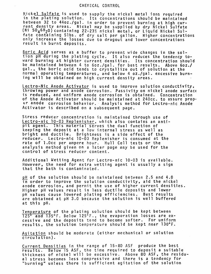
Nickel Sulfate is used to supply the nickel metal ions required in the plating solution. Its concentrations should be maintained between 32 to 44oz./gal. in order to prevent burning at high cur¬ rent density areas. Nickel may be supplied by dry Nickel Sulfate (Ni SO46H2O) containing 22-23% nickel metal, or Liquid Nickel Sul¬ fate containing 51bs. of dry salt per gallon. Higher concentrations only increase the losses due to dragout and lower concentrations result in burnt deposits.
Boric Acid serves as a buffer to prevent wide changes in the sol- tion pH during the plating cycle. It also reduces the tendency to¬ ward burning at highter current densities. Its concentration should be maintained between 4 to 6oz./gal. for best results. Above 6oz./ gal., the boric acid tends to crystallize out of solution at the normal operating temperatures, and below 4 oz./gal. excessive burn¬ ing will be obtained on high current density areas.
Lectro-Nic Anode Activator is used to improve solution conductivity, throwing power and anode corrosion. Passivity on nickel anode surface is reduced, and uniform anode corrosion is obtained. Concentration of the Anode Activator should be maintained at 240cc. to assure prop¬ er anode corrosion behavior. Analysis method for Lectro-nic Anode
Activator is described on a subsequent page.
Stress reducer concentration is maintained through use of Lectro-nic 10-03 Replenisher, which also contains an anti- pit agent. This material serves the dual function of keeping the deposit at a low internal stress as well as bright and ductile. Brightness is a side effect of the reducer. Lectro-nic 10-03 Replenisher is consumed at the rate of 1 .Occ per ampere hour. Hull Cell tests or the analysis method given on a later page may be used for the control of stress reducer content.
Additional Wetting Agent for Lectro-nic 10-03 is available. However, the need for extra wetting agent is usually a sign that the bath is contaminated.
pH of the solution should be maintained between 2.5 and 4.0 in order to improve the solution conductivity, aid the nickel anode corrosion, and permit the use of higher current densities. Higher pH values result in less ductile deposits and lower pH values cause lowered plating efficiencies. Best results are obtained at pH 3.0 because the solution is well buffered at this pH.
Temperature of the plating solution should be kept between 125° and 1350F. Below 1250F., the evaporation losses are ex¬ cessive and the deposits tend to become softer. For uniform results, the solution temperature should be kept near 130oF.
Ag i ta ti on should be moderate (either mechanical or solution ci rcu1 ati on).
Current Densities in the range of 15-80 ASF produce the best results. Below 15 ASF, the time required to deposit a suitable thickness of nickel will be excessive. Above 80 ASF, the residu¬ al stress becomes less compressive and there is a tendency for "burning" unless there is sufficient agitation of the solution
Lectro-Nic 10-03
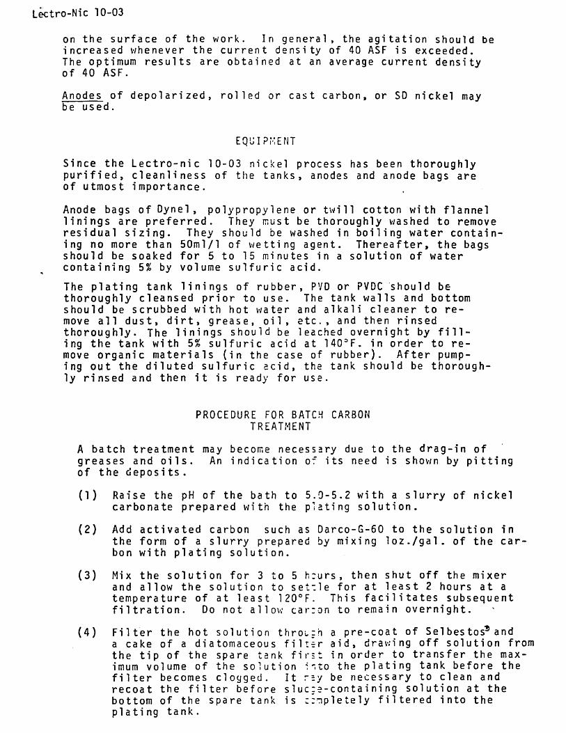
on the surface of the work. In general, the agitation should be increased whenever the current density of 40 ASF is exceeded. The optimum results are obtained at an average current density of 40 ASF.
Anodes of depolarized, rolled or cast carbon, or SD nickel may be used.
EQUIP r' E N T
Since the Lectro-nic 10-03 nickel process has been thoroughly purified, cleanliness of the tanks, anodes and anode bags are of utmost importance.
Anode bags of Dyne! , polypropylene or twill cotton with flannel linings are preferred. They must be thoroughly washed to remove residual sizing. They should be washed in boiling water contain¬ ing no more than 50ml/l of wetting agent. Thereafter, the bags should be soaked for 5 to 15 minutes in a solution of water containing 5% by volume sulfuric acid.
The plating tank linings of rubber, PVD or PVDC should be thoroughly cleansed prior to use. The tank walls and bottom should be scrubbed with hot water and alkali cleaner to re¬ move all dust, dirt, grease, oil, etc., and then rinsed thoroughly. The linings should be leached overnight by fill¬ ing the tank with 5% sulfuric acid at 140:>F. in order to re¬ move organic materials (in the case of rubber). After pump¬ ing out the diluted sulfuric acid, the tank should be thorough¬ ly rinsed and then it is ready for use.
PROCEDURE FOR BATCH CARBON TREATMENT
A batch treatment may become necessary due to the drag-in of greases and oils. An indication of its need is shown by pitting of the deposi ts .
(1) Raise the pH of the bath to 5.9-5.2 with a slurry of nickel carbonate prepared with the plating solution.
(2) Add activated carbon such as Darco-G-60 to the solution in the form of a slurry prepared by mixing loz./gal. of the car¬ bon with plating solution.
(3) Mix the solution for 3 to 5 h:urs, then shut off the mixer and allow the solution to setile for at least 2 hours at a temperature of at least 120oF. This facilitates subsequent filtration. Do not allow car:on to remain overnight.
(4) Filter the hot solution throiz'n a pre-coat of Sel bes tos*5 and a cake of a diatomaceous filter aid, drawing off solution from the tip of the spare tank first in order to transfer the max¬ imum volume of the solution into the plating tank before the filter becomes clogged. It rsy be necessary to clean and recoat the filter before s 1 uc:e-containing solution at the bottom of the spare tank is c:"npletely filtered into the plating tank.
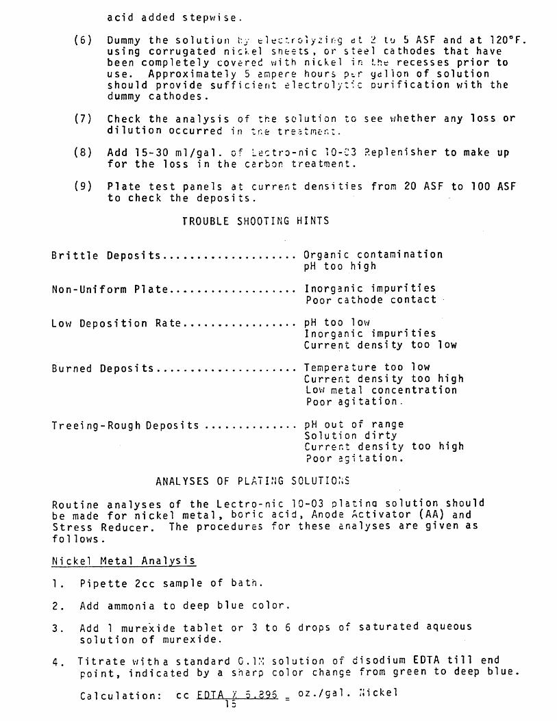
acid added stepwise.
Dummy the solution l:y tlec'rolyzirg dt 2 to S ASF and at 120oF. using corrugated nickel sneets , or steel cathodes that have been completely covered with nickel in !.he recesses prior to use. Approximately 5 empere hours p-.r ydllon of solution should provide sufficient electrolytic purification with the dummy cathodes .
Check the analysis of the solution to see whether any loss or dilution occurred in tr.e trestmer.
Add 15-30 ml/gal. of Lectro-nic i0-C3 P.eplenisher to make up for the loss in the carbon treatment.
Plate test panels at current densities from 20 ASF to 100 ASF to check the deposits.
TROUBLE SHOOTING HINTS
Brittle Deposits Organic contamination pH too high
Non-Uniform Plate Inorganic impurities Poor cathode contact
Low Deposition Rate pH too low Inorganic impurities Current density too low
Burned Deposits Temperature too low Current density too high Low metal concentration Poor agitation.
Tr eei ng - Roug h Deposits pH out of range Solution dirty Current density too high Poor agitation.
ANALYSES OF PLATING SOLUTIONS
Routine analyses of the Lectro-nic 10-03 platinq solution should be made for nickel metal, boric acid, Anode Activator (AA) and Stress Reducer. The procedures for these analyses are given as fol1ows .
Nickel Metal Analysis
1. Pipette 2cc sample of bath.
2. Add ammonia to deep blue color.
3. Add 1 murexide tablet or 3 to 5 drops of saturated aqueous solution of murexide.
4. Titrate with a standard 0.1M solution of di sodium EDTA till end point, indicated by a sharp color change from green to deep blue.
Calculation: cc EDTA X 5.395 _ oz./gal. nickel
(6)
(7)
(8)
(9)
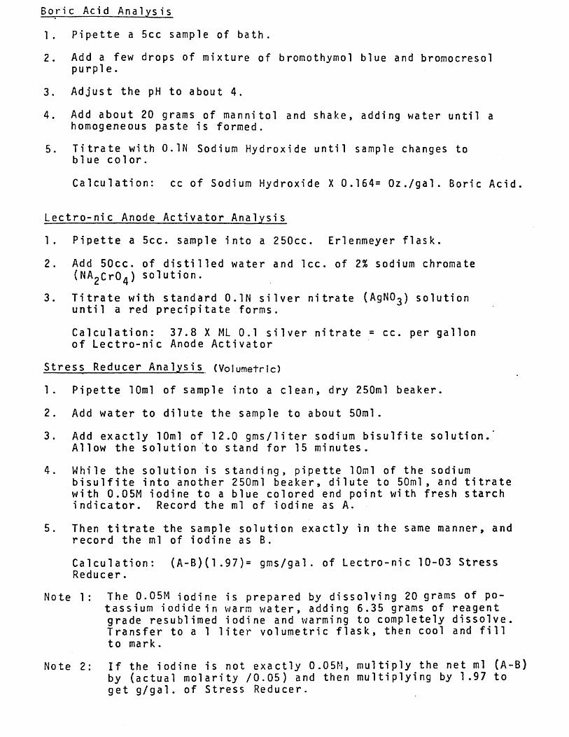
Boric Acid Analysis
1. Pipette a 5cc sample of bath.
2. Add a few drops of mixture of bromothymol blue and bromocresol purple.
3. Adjust the pH to about 4.
4. Add about 20 grams of mannitol and shake, adding water until a homogeneous paste is formed.
5. Titrate with 0.1N Sodium Hydroxide until sample changes to b1ue col or.
Calculation: cc of Sodium Hydroxide X 0.164= Oz./gal. Boric Acid.
Lectro-nic Anode Activator Analysis
1. Pipette a 5cc. sample into a 250cc. Erlenmeyer flask.
2. Add 50cc. of distilled water and lee. of 2% sodium chromate (NA2Cr04) solution.
3. Titrate with standard 0.1N silver nitrate (AgNO^) solution until a red precipitate forms.
Calculation: 37.8 X ML 0.1 silver nitrate = cc. per gallon of Lectro-nic Anode Activator
Stress Reducer Analysis (Volumetric)
1. Pipette 10ml of sample into a clean, dry 250ml beaker.
2. Add water to dilute the sample to about 50ml.
3. Add exactly 10ml of 12.0 gms/liter sodium bisulfite solution.' Allow the solution to stand for 15 minutes.
4. While the solution is standing, pipette 10ml of the sodium bisulfite into another 250ml beaker, dilute to 50ml, and titrate with 0.05M iodine to a blue colored end point with fresh starch indicator. Record the ml of iodine as A.
5. Then titrate the sample solution exactly in the same manner, and record the ml of iodine as B.
Calculation: (A-B)(1.97)= gms/gal . of Lectro-nic 10-03 Stress Reducer.
Note 1: The 0.05M iodine is prepared by dissolving 20 grams of po¬ tassium iodide in warm water, adding 6.35 grams of reagent grade resublimed iodine and warming to completely dissolve. Transfer to a 1 liter volumetric flask, then cool and fill to mark.
Note 2: If the iodine is not exactly 0.05M, multiply the net ml (A-B) by (actual molarity /0.05) and then multiplying by 1.97 to get g/gal. of Stress Reducer.
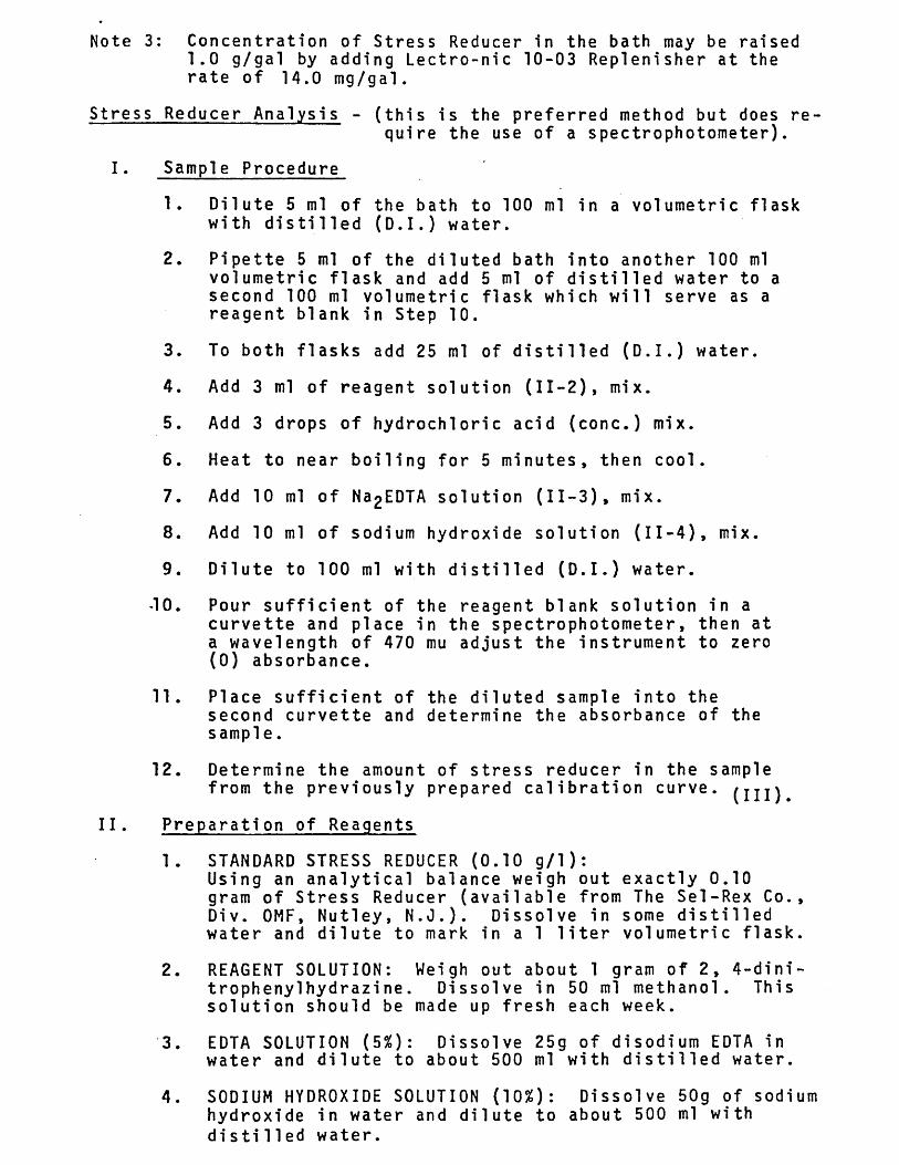
Note 3: Concentration of Stress Reducer in the bath may be raised 1.0 g/gal by adding Lectro-nic 10-03 Replenisher at the rate of 14.0 mg/gal.
Stress Reducer Analysis - (this is the preferred method but does re¬ quire the use of a spectrophotometer).
I. Sample Procedure
1. Dilute 5 ml of the bath to 100 ml in a volumetric flask with distilled (D.I.) water.
2. Pipette 5 ml of the diluted bath into another 100 ml volumetric flask and add 5 ml of distilled water to a second 100 ml volumetric flask which will serve as a reagent blank in Step 10.
3. To both flasks add 25 ml of distilled (D.I.) water.
4. Add 3 ml of reagent solution (11-2), mix.
5. Add 3 drops of hydrochloric acid (conc.) mix.
6. Heat to near boiling for 5 minutes, then cool.
7. Add 10 ml of Na2EDTA solution (II-3), mix.
8. Add 10 ml of sodium hydroxide solution (II-4), mix.
9. Dilute to 100 ml with distilled (D.I.) water.
-10. Pour sufficient of the reagent blank solution in a curvette and place in the spectrophotometer, then at a wavelength of 470 mu adjust the instrument to zero (0) absorbance.
11. Place sufficient of the diluted sample into the second curvette and determine the absorbance of the sample.
12. Determine the amount of stress reducer in the sample from the previously prepared calibration curve, (mj
11. Preparation of Reagents
1. STANDARD STRESS REDUCER (0.10 g/1): Using an analytical balance weigh out exactly 0.10 gram of Stress Reducer (available from The Sel-Rex Co., Div. 0MF, Nutley, N.J.). Dissolve in some distilled water and dilute to mark in a 1 liter volumetric flask.
2. REAGENT SOLUTION: Weigh out about 1 gram of 2, 4-dini- trophenylhydrazine. Dissolve in 50 ml methanol. This solution should be made up fresh each week.
3. EDTA SOLUTION (5%): Dissolve 25g of disodium EDTA in water and dilute to about 500 ml with distilled water.
4. SODIUM HYDROXIDE SOLUTION (10%): Dissolve 50g of sodium hydroxide in water and dilute to about 500 ml with distilled water.
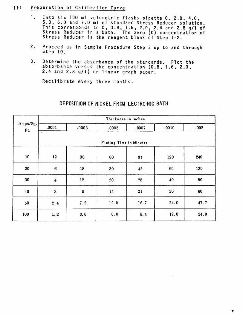
III. Preparation of Calibration Curve
1. Into six 100 ml volumetric flasks pipette 0, 2.0, 4.0, 5.0, 6.0 and 7.0 ml of standard Stress Reducer solution. This corresponds to 0, 0.8, 1.6, 2.0, 2.4 and 2.8 g/1 of Stress Reducer in a bath. The zero (0) concentration of Stress Reducer is the reagent blank of Step 1-2.
2. Proceed as in Sample Procedure Step 3 up to and through Step 10.
3. Determine the absorbance of the standards. Plot the absorbance versus the concentration (0.8, 1.6, 2.0, 2.4 and 2.8 g/1) on linear graph paper.
Recalibrate every three months.
DEPOSITION OF NICKEL FRCM LECTRO-NIC BATH
Amps/Sq.
Ft.
Thickness in inches
.0001 .0003 .0005 .0007 .0010 .002
Plating Time in Minutes
10 12 36 60 84 120 240
20 6 18 30 42 60 120
30 4 12 20 28 40 80
40 3 9 15 21 30 60
50 2.4 7.2 12.0 16.7 24.0 47.7
100 1.2 3.6 6.0 8.4 12.0 24.0
■n_^ ly'J >
a^^^'-'.'.'.^'li,. * ; • ^:'i;«w;rv".:;segNTj-VKiy':^'(Si§lSk3
Plating Product
Bulletin No. 50
Decorative Chromium Plating
In decorative chromium plating, thin, nontarnishing, durable coatings of chro¬ mium are deposited over metal surfaces — usually nickel-plated surfaces. To deposit chromium, the electroplating solution must contain not only chromic acid, but one or more acid radicals capable of catalyzing the chromium deposition at the cathode. The sulfate ion, supplied by sulfuric acid, is the catalyst in conventional baths. For the versatile high-speed performance needed in today's decorative plating operations, however, chromium baths require mixed-catalyst systems. Du Font's Decorative Chromium Plating Compounds provide such systems.
This bulletin gives general operating instructions for Du Pont decorative chromium plating processes. Bath make-up and control as well as the simple procedures used to maintain baths within preferred limits are discussed. These general operating instructions amplify and supplement specific recommendations made in separate bulletins on decorative plating with Du Pont Chromium Plating Compounds. Your Du Pont Representative or Distributor of Du Pont Chromium Plating Products can supply them.
Contents Page
Bath Composition 2 Chromic Acid Concentration Chromic Acid/Sulfate Ratio - Trivalent Chromium Concentration - Temperature - Current Density 2
Operating Conditions 2 Power Demand ^ Anode Usage ^ Rack Usage ^ Nickel Surface ^ Rinsing Before and After Chromium Plating 5 Trivalent Chromium Oxidation 5
Bath Control and Maintenance 7 Routine Control Procedures 7 Analytical Procedures 8 Modified Hull Cell Tests II
Common Plating Problems 13
Equipment 16
Personal Safety 18
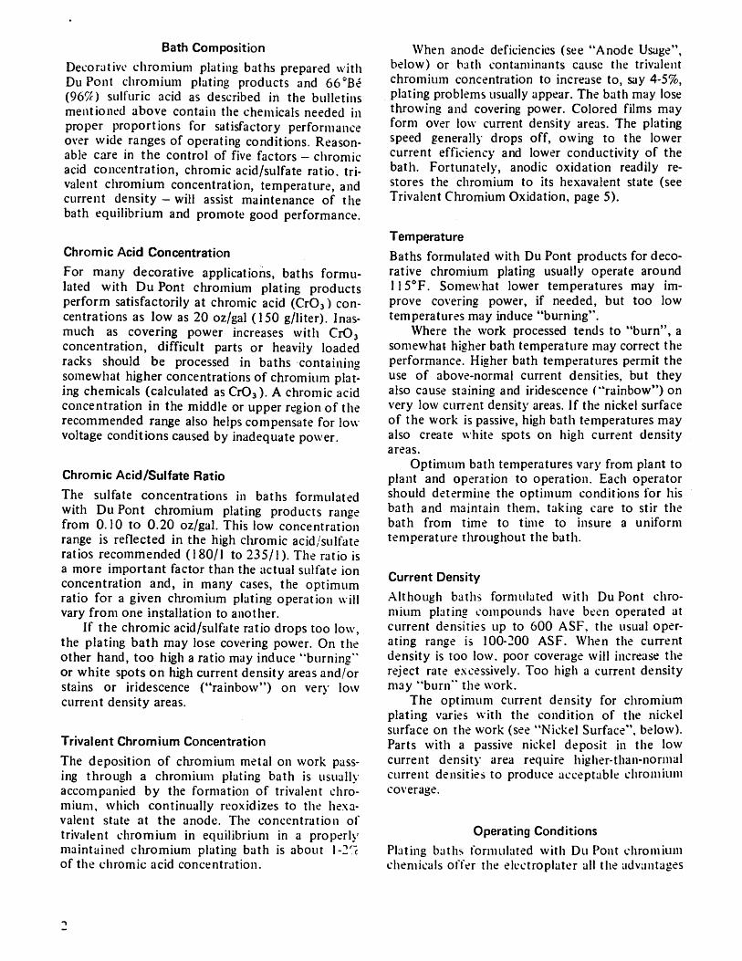
Bath Composition
Decorative chromium plating baths prepared with Du Pont chromium plating products and 660Be (96#) sulfuric acid as described in the bulletins mentioned above contain the chemicals needed in proper proportions for satisfactory performance over wide ranges of operating conditions. Reason¬ able care in the control of five factors - chromic acid concentration, chromic acid/sulfate ratio, tri- valent chromium concentration, temperature, and current density - will assist maintenance of the bath equilibrium and promote good performance.
Chromic Acid Concentration
For many decorative applications, baths formu¬ lated with Du Pont chromium plating products perform satisfactorily at chromic acid (CrCM con¬ centrations as low as 20 oz/gal (150 g/liter). Inas¬ much as covering power increases with Cr03
concentration, difficult parts or heavily loaded racks should be processed in baths containing somewhat higher concentrations of chromium plat¬ ing chemicals (calculated as CrOa). A chromic acid concentration in the middle or upper region of the recommended range also helps compensate for low voltage conditions caused by inadequate power.
Chromic Acid/Sulfate Ratio
The sulfate concentrations in baths formulated with Du Pont chromium plating products range from 0.10 to 0.20 oz/gal. This low concentration range is reflected in the high chromic acid/sulfate ratios recommended (180/1 to 235/1). The ratio is a more important factor than the actual sulfate ion concentration and, in many cases, the optimum ratio for a given chromium plating operation will vary from one installation to another.
If the chromic acid/sulfate ratio drops too low, the plating bath may lose covering power. On the other hand, too high a ratio may induce ''burning" or white spots on high current density areas and/or stains or iridescence ("rainbow") on very low current density areas.
Trivalent Chromium Concentration
The deposition of chromium metal on work pass¬ ing through a chromium plating bath is usually accompanied by the formation of trivalent chro¬ mium, which continually reoxidizes to the hexa- valent state at the anode. The concentration of trivalent chromium in equilibrium in a properly maintained chromium plating bath is about l-2r~c of the chromic acid concentration.
When anode deficiencies (see "Anode Usage", below) or bath contaminants cause the trivalent chromium concentration to increase to, say 4-5%, plating problems usually appear. The bath may lose throwing and covering power. Colored films may form over low current density areas. The plating speed generally drops off, owing to the lower current efficiency and lower conductivity of the bath. Fortunately, anodic oxidation readily re¬ stores the chromium to its hexavalent state (see Trivalent Chromium Oxidation, page 5).
Temperature
Baths formulated with Du Pont products for deco¬ rative chromium plating usually operate around 1150F. Somewhat lower temperatures may im¬ prove covering power, if needed, but too low temperatures may induce "burning".
Where the work processed tends to "burn", a somewhat higher bath temperature may correct the performance. Higher bath temperatures permit the use of above-normal current densities, but they also cause staining and iridescence ("rainbow") on very low current density areas. If the nickel surface of the work is passive, high bath temperatures may also create white spots on high current density areas.
Optimum bath temperatures vary from plant to plant and operation to operation. Each operator should determine the optimum conditions for his bath and maintain them, taking care to stir the bath from time to time to insure a uniform temperature throughout the bath.
Current Density
Although baths formulated with Du Pont chro¬ mium plating compounds have been operated at current densities up to 600 ASF, the usual oper¬ ating range is 100-200 ASF. When the current density is too low. poor coverage will increase the reject rate excessively. Too high a current density may "bum" the work.
The optimum current density for chromium plating varies with the condition of the nickel surface on the work (see "Nickel Surface", below). Parts with a passive nickel deposit in the low current density area require higher-than-normal current densities to produce acceptable chromium coverage.
Operating Conditions
Plating baths formulated with Du Pont chromium chemicals offer the electroplater all the advantages
-i
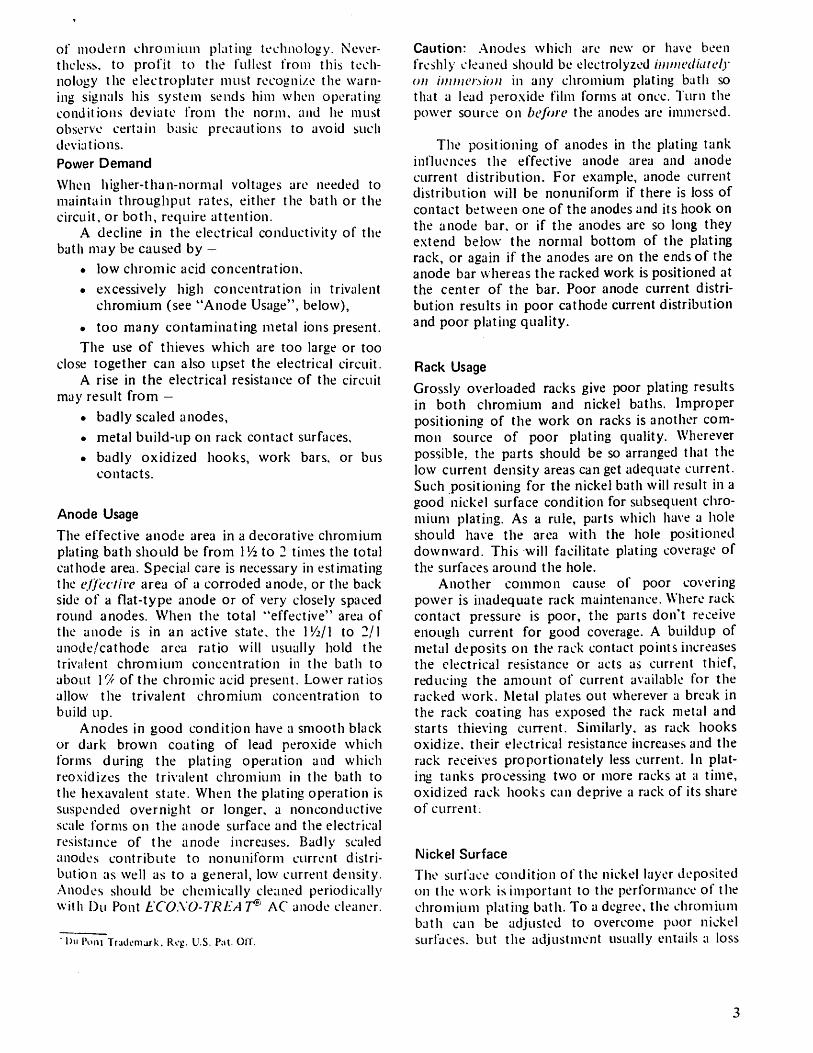
of modern chromium plating technology. Never¬ theless, to profit to the fullest from this tech¬ nology the electroplater must recogni/e the warn¬ ing signals his system sends him when operating conditions deviate from the norm, and he must observe certain basic precautions to avoid such deviations. Power Demand
When higher-than-normal voltages are needed to maintain throughput rates, either the bath or the circuit, or both, require attention.
A decline in the electrical conductivity of the bath may be caused by —
• low chromic acid concentration.
• excessively high concentration in trivalent chromium (see ''Anode Usage", below),
• too many contaminating metal ions present.
The use of thieves which are too large or too close together can also upset the electrical circuit.
A rise in the electrical resistance of the circuit may result from -
• badly scaled anodes,
• metal build-up on rack contact surfaces,
• badly oxidized hooks, work bars, or bus contacts.
Anode Usage
The effective anode area in a decorative chromium plating bath should be from IVz to 2 times the total cathode area. Special care is necessary in estimating the effective area of a corroded anode, or the back side of a flat-type anode or of very closely spaced round anodes. When the total "effective" area of the anode is in an active state, the P/a/l to 2/1 anode/cathode area ratio will usually hold the trivalent chromium concentration in the bath to about VA of the chromic acid present. Lower ratios allow the trivalent chromium concentration to build up.
Anodes in good condition have a smooth black or dark brown coating of lead peroxide which forms during the plating operation and which reoxidizes the trivalent cliromium in the bath to the hexavalent state. When the plating operation is suspended overnight or longer, a nonconductive scale forms on the anode surface and the electrical resistance of the anode increases. Badly scaled anodes contribute to nonuniform current distri¬ bution as well as to a general, low current density. Anodes should be chemically cleaned periodically with Du Pont ECOSO-TRliAT® AC anode cleaner.
" Du Pont Trademark. Reg. U.S. Pat. OH".
Caution: Anodes which are new or have been freshly cleaned should be electrolyzed immeclhttely on immersion in any chromium plating bath so that a lead peroxide film forms at once. Turn the power source on before the anodes are immersed.
The positioning of anodes in the plating tank influences the effective anode area and anode current distribution. For example, anode current distribution will be nonuniform if there is loss of contact between one of the anodes and its hook on the anode bar. or if the anodes are so long they extend below the normal bottom of the plating rack, or again if the anodes are on the ends of the anode bar whereas the racked work is positioned at the center of the bar. Poor anode current distri¬ bution results in poor cathode current distribution and poor plating quality.
Rack Usage
Grossly overloaded racks give poor plating results in both chromium and nickel baths. Improper positioning of the work on racks is another com¬ mon source of poor plating quality. Wherever possible, the parts should be so arranged that the low current density areas can get adequate current. Such positioning for the nickel bath will result in a good nickel surface condition for subsequent chro¬ mium plating. As a rule, parts which have a hole should have the area with the hole positioned downward. This will facilitate plating coverage of the surfaces around the hole.
Another common cause of poor covering power is inadequate rack maintenance. Where rack contact pressure is poor, the parts don't receive enough current for good coverage. A buildup of metal deposits on the rack contact points increases the electrical resistance or acts as current thief, reducing the amount of current available for the racked work. Metal plates out wherever a break in the rack coating has exposed the rack metal and starts thieving current. Similarly, as rack hooks oxidize, their electrical resistance increases and the rack receives proportionately less current. In plat¬ ing tanks processing two or more racks at a time, oxidized rack hooks can deprive a rack of its share of current.
Nickel Surface
The surface condition of the nickel layer deposited on the work is important to the performance of the chromium plating bath. To a degree, the chromium bath can be adjusted to overcome poor nickel surfaces, but the adjustment usually entails a loss
3
in the covering power of the chromium bath or an increase in the concentration of the bath.
On the other hand, the plating shop operator gains several economic benefits if he increases the quality ol his nickel deposits and rinses them well. Me gets:
• equivalent chromium plating performance from baths containing much lower concen¬ trations of chromic acid,
• commensurately lower waste treatment costs,
• a potential saving in nickel brightener consumption.
Rinsing the nickel plated work thoroughly reduces solution dragout and its contamination of the chromium bath. A fog rinsing system above the nickel plating tank is especially effective: it re¬ moves most of the nickel solution from the racks and work emerging from the plating bath, yet the volume of water used is generally less than the amount needed to replace bath evaporation losses. Chemical dragout losses to the rinse tanks through which the work then passes are minimal, as are waste treatment costs.
The procedure for improving the quality of the nickel plate depends upon whether the deficiency is in low current density areas or in high current density areas.
Low Current Density Areas
Low current density areas with a low quality nickel surface usually require processing in a high concen¬ tration chromium bath to get adequate coverage. A better practice, from the standpoint of both overall economy and product quality, is to improve the quality ot the nickel deposit on the low current density areas. Three precautions are necessary:
A — Keep the nickel bath clean.
1 — Keep foreign metal ion concentrations low by frequent electrolytic purifica¬ tion.
2 - Hold organic impurities to a minimum with periodic carbon treatment.
3 - Purify the bath with a high pH treat¬ ment as soon as plating quality drops off.
B — Use the highest average current density that is practical to deposit a good quality nickel surface over low current density areas.
C - Activate the nickel surface (see below).
High Current Density Areas
High current density areas with a poor nickel surface tend to give a white blotchy appearance to the chromium deposit. The remedy for this is both simple and economical:
A - Hold the nickel brightener concentration to the minimum needed for the desired nickel finish and color.
1 - Add only small amounts of the brightener at a time.
2 - Make the small additions at frequent [h-rhdic intervals.
B - Activate the nickel surface (see below).
Activation of the Nickel Surface
Activation of the nickel surface improves its per¬ formance as cathode in the chromium plating bath. Activation removes or significantly reduces defi¬ ciencies inherent in most production nickel de¬ posits. The plater has a choice of three methods of activation:
Acid Activation with Rinsing
Acid Activation without Rinsing
Warm-Water Rinse Activation
Acid Activation with Rinsing
Acid activation with rinsing uses an acidic solution such as obtained with Du Pont ECOXO-TREAT® NA nickel activator. The nickel plated work is thoroughly rinsed, immersed for 15-30 seconds in a solution containing 4 oz ECONO-TREA T NA per gallon of water, then again rinsed prior to chro¬ mium plating.
Note: The activator solution should be maintained at recommended strength by adding, prior to each day's operation. Vj oz ECO.XO-TREAT NA for each gallon of solution and by replacing the activator solution each week.
Acid Activation without Rinsing
Acid activation without rinsing uses a solution of the Du Pont chromium plating product or of chro¬ mic acid for the activation dip. The nickel plated work, thoroughly rinsed, is immersed for 15-30 seconds in a solution containing Va-Vi oz of the Du Pont product or of chromic acid per gallon of w ater. The dipped work then passes directly to the chromium plating tank.
-Du Pont Trjdcnurk. Reg. L'.S. Pat. OtY.
4
Note: The activator solution should be maintained at recommended strength by adding, prior to each day's operation, 1/16 to J/8 oz Du Pont product (or chromic acid) for each gallon of solution and by replacing the activator dip each week.
Warm Water Rinse Activation
Warm water rinse activation uses a final rinse in water at 100-120oF (below ]00oF if parts dry before entering the chromium plating bath) to Sctivate the nickel surface. The nickel plated work, thoroughly rinsed, is immersed for 15-30 seconds in the warm water rinse. The fresh water feed to the tank should be at a rate which gives total replacement in a week's time.
Note: Warm water rinse activation is more effective on low current density areas than on high current density areas.
Trivalent Chromium Oxidation
When anode deficiencies or bath contaminants (decomposition products of nickel brighteners, wetting agents, unstable mist suppressants — or stray parts corroding on the floor of the tank) allow the trivalent chromium concentration to exceed the recommended maximum of around 2%, reoxidation is necessary. This can be done using the tank anodes as follows:
1. Increase the chromium plating bath tem¬ perature to at least 1450F, or the temper-
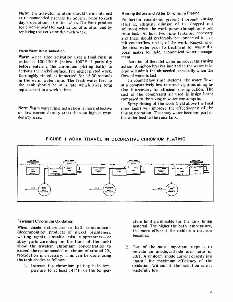
Rinsing Before and After Chromium Plating
Production conditions prevent thorough rinsing (that is, adequate dilution of the dragged out solution) when the work passes through only one rinse tank. At least two rinse tanks are necessary and these should preferably be connected to per¬ mit counterflow rinsing of the work. Recycling ol the rinse water prior to treatment for waste dis¬ posal makes for safe, economical water manage¬ ment.
Aeration of the inlet water improves the rinsing action. A siphon breaker inserted in the water inlet pipe will admit the air needed, especially when the flow of water is fast.
In counterflow rinse systems, the water flows at a comparatively low rate and vigorous air agita¬ tion is necessary for efficient rinsing action. The cost of the compressed air used is insignificant compared to the saving in water consumption.
Spray rinsing of the work (held above the final rinse tank) will improve the effectiveness of the rinsing operation. The spray water becomes part of the water feed to the rinse tank.
ature limit permissible for the tank lining material. The higher the bath temperature, the more efficient the oxidation reaction becomes.
2. One of the most important steps is to provide an anode/cathode area ratio of 30/1. A uniform anode current density is a "must" for maximum efficiency of the oxidation. Without it, the oxidation rate is wastefully low.
FIGURE 1 WORK TRAVEL IN DECORATIVE CHROMIUM PLATING
5
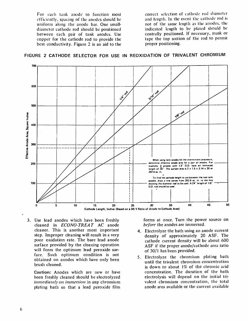
For each tunk anode to function most efficiently, spacing of the anodes should be uniform along the anode bar. One small- diameter cathode rod should be positioned between each pair of tank anodes. Use copper for the cathode rod to provide the best conductivity. Figure 2 is an aid to the
correct selection of cathode rod diameter and length. In the event the cathode rod is not of the same length as the anodes, the indicated length to be plated should be centrally positioned. If necessary, mask or tape the top section of the rod to permit proper positioning.
FIGURE 2 CATHODE SELECTOR FOR USE IN REOXIDATION OF TRIVALENT CHROMIUM
700
600
500
S 400
300
200
100
0 5 10 15 20 25 30 35 40 45 50 Cathode Length, Inches (Based on a 30:1 Ratio of Anode to Cathode Area)
3. Use lead anodes which have been freshly cleaned in ECONO-TREA T AC anode cleaner. This is another most important step. Improper cleaning will result in a very poor oxidation rate. The bare lead anode surface provided by the cleaning operation will form the optimum lead peroxide sur¬ face. Such optimum condition is not obtained on anodes which have only been brush cleaned.
Caution: Anodes which are new or have been freshly cleaned should be electrolyzed immediately on immersion in any chromium plating bath so that a lead peroxide film
forms at once. Turn the power source on before the anodes are immersed.
4. Electrolyze the bath using an anode current density of approximately 20 ASF. The cathode current density will be about 600 ASF if the proper anode/cathode area ratio of 30/1 has been provided.
5. Electrolyze the chromium plating bath until the trivalent chromium concentration is down to about 1% of the chromic acid concentration. The duration of the bath electrolysis will depend on the initial tri¬ valent chromium concentration, the total anode area available or the current available
6
for the particular bath volume, and the temperature of the bath. The efficiency of oxidation will decline as the trivalent chro¬ mium concentration drops. For example, less electrolysis will be needed to lower the trivalent chromium level from 5% to Af'A than to reduce it from 2$ to V/i. It may be necessary to electrolyze the bath for several overnight periods or over a weekend to lower the trivalent chromium concen¬ tration to the desired level (1% of the chromic acid present).
Using a current/volume ratio of 5 A/gal of solution, an anode current density of 20 ASF, and a cathode current density of 600 ASF, approximately two hours of elec¬ trolysis (on the average) will reduce the trivalent chromium level 0.1 oz/gal.
Bath Control and Maintenance
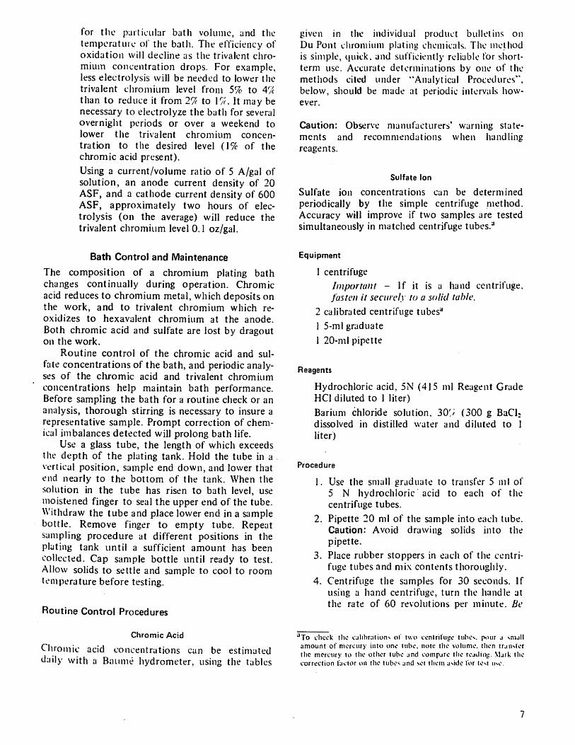
The composition of a chromium plating bath changes continually during operation. Chromic acid reduces to chromium metal, which deposits on the work, and to trivalent chromium which re- oxidizes to hexavalent chromium at the anode. Both chromic acid and sulfate are lost by dragout on the work.
Routine control of the chromic acid and sul¬ fate concentrations of the bath, and periodic analy¬ ses of the chromic acid and trivalent chromium concentrations help maintain bath performance. Before sampling the bath for a routine check or an analysis, thorough stirring is necessary to insure a representative sample. Prompt correction of chem¬ ical imbalances detected will prolong bath life.
Use a glass tube, the length of which exceeds the depth of the plating tank. Hold the tube in a vertical position, sample end down, and lower that end nearly to the bottom of the tank. When the solution in the tube has risen to bath level, use moistened finger to seal the upper end of the tube. Withdraw the tube and place lower end in a sample bottle. Remove finger to empty tube. Repeat sampling procedure at different positions in the plating tank until a sufficient amount has been collected. Cap sample bottle until ready to test. Allow solids to settle and sample to cool to room temperature before testing.
Routine Control Procedures
Chromic Acid
Chromic acid concentrations can be estimated daily with a Baume hydrometer, using the tables
given in the individual product bulletins on Du Pont chromium plating chemicals. The method is simple, quick, and sufficiently reliable for short- term use. Accurate determinations by one of the methods cited under "Analytical Procedures", below, should be made at periodic intervals how¬ ever.
Caution: Observe manufacturers' warning state¬ ments and recommendations when handling reagents.
Sulfate Ion
Sulfate ion concentrations can be determined periodically by the simple centrifuge method. Accuracy will improve if two samples are tested simultaneously in matched centrifuge tubes.3
Equipment
1 centrifuge
Important - If it is a hand centrifuge. fasten it securely to a solid table.
2 calibrated centrifuge tubes"
1 5-ml graduate
1 20-ml pipette
Reagents
Hydrochloric acid, 5N (415 ml Reagent Grade HC1 diluted to 1 liter)
Barium chloride solution. 30'; (300 g BaCl; dissolved in distilled water and diluted to 1 liter)
Procedure
1. Use the small graduate to transfer 5 ml of 5 N hydrochloric acid to each of the centrifuge tubes.
2. Pipette 20 ml of the sample into each tube. Caution: Avoid drawing solids into the pipette.
3. Place rubber stoppers in each of the centri¬ fuge tubes and mix contents thoroughly.
4. Centrifuge the samples for 30 seconds. If using a hand centrifuge, turn the handle at the rate of 60 revolutions per minute. Be
aTo check the calibrations of two centrifuge tuhex. pour a small amount of mercury into one tube, note the volume, then transfer the mercury to the other tube and compare the reailiiu:. Mark the correction factor on the tubes and set them aside for lest use.
7
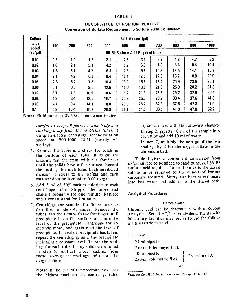
TABLE I
DECORATIVE CHROMIUM PLATING Conversion of Sulfate Requirement to Sulfuric Acid Equivalent
Sulfate to be added
(oz/gal)
Bath Volume (gal)
100 200 300 400 500 600 700 800 900 1000
66° Be Sulfuric Acid Required (fl oz)
0.01 0.5 1.0 1.6 2.1 2.6 3.1 3.7 4.2 4.7 5.2
0.02 1.0 2.1 3.1 4.2 5.2 6.3 7.3 8.4 9.4 10.4
0.03 1.6 3.1 4.7 6.3 7.8 9.6 10.9 12.5 14.1 15.7
0.04 2.1 4.2 6.3 8.4 10.4 12.5 14.6 16.7 18.8 20.9
0.05 2.6 5.2 7.8 10.4 13.0 15.6 18.2 20.9 23.5 26.1
0.06 3.1 6.3 9.6 12.5 15.6 18.8 21.9 25.0 28.2 31.3
0.07 3.7 7.3 10.9 14.6 18.2 21.9 25.6 29.2 32.9 36.5
0.08 4.2 8.4 12.5 16.7 20.9 25.0 29.2 33.4 37.6 41.8
0.09 4.7 9.4 14.1 18.8 23.5 28.2 32.9 37.6 42.3 47.0
0.10 5.2 10.4 15.7 20.9 26.1 • 31.3 36.5 41.8 47.0 52.2
Mote: Fluid ounces x 29.5737 = cubic centimeters.
careful to keep all parts of your body and clothing away from the revolving tubes. If using an electric centrifuge, set the rotation speed at 900-1000 RPM (usually =1 setting).
5. Remove the tubes and check for solids in the bottom of each tube. If solids are present, tap the stem with the forefinger until the solids have a flat surface. Record the readings for each tube. Each numbered division is equal to 0.1 oz/gal and each smallest division is equal to 0.02 oz/gal.
6. Add 5 ml of 30% barium chloride to each centrifuge tube. Stopper the tubes and shake thoroughly for one minute. Replace and allow to stand for 5 minutes.
7. Centrifuge the samples for 30 seconds as described in step 4, above. Remove the tubes, tap the stem with the forefinger until precipitate has a flat surface, and note the level of the precipitate. Centrifuge for 15 seconds more, and again read the level of precipitate. If level of precipitate has fallen, repeat the centrifuging until the precipitate maintains a constant level. Record the read¬ ings for each tube. If any solids were found in step 5, subtract those readings from these. Average the readings and record the oz/gal sulfate.
Note: If the level of the precipitate exceeds the highest mark on the centrifuge tube,
repeat the test with the following changes:
In step 2, pipette 10 ml of the sample into each tube and add 10 ml of water.
In step 7, multiply the average of the two readings by 2 for the oz/gal sulfate in the chromium bath.
Table I gives a convenient conversion from oz/gal sulfate to be added to fluid ounces of 66° sulfuric acid required. Table II converts the oz/gal sulfate to be removed to the ounces of barium carbonate required. Slurry the barium carbonate into hot water and add it to the stirred bath.
Analytical Procedures
Chromic Acid
Chromic acid can be determined with a Kocour Analytical Set "CA",b or equivalent. Plants with laboratory facilities may prefer to use the follow¬ ing titrimetric method.
Equipment
25-ml pipette
250-ml Erlenmeyer flask
10-ml pipette
250-ml volumetric flask Procedure 1A
or
^Kocour Co.. 4800 So. St. Louis Ave.. Chicago. IL 60632
8
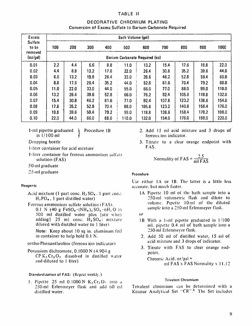
TABLE II
DECORATIVE CHROMIUM PLATING Conversion of Excess Sulfate to Barium Carbonate Required
Excess Bath Volume (gal) Sulfate to be
removed 100 200 300 400 500 600 700 800 900 1000
(oz/gal) Barium Carbonate Required (oz)
0.01 2.2 4.4 6.6 8.8 11.0 13.2 15.4 17.6 19.8 22.0
0.02 4.4 8.8 13.2 17.6 22.0 26.4 30.8 35.2 39.6 44.0
0.03 6.6 13.2 19.8 26.4 33.0 39.6 46.2 52.8 59.4 66.0
0.04 8.8 17.6 26.4 35.2 44.0 52.8 61.6 70.4 79.2 88.0
0.05 11.0 22.0 33.0 44.0 55.0 66.0 77.0 88.0 99.0 110.0
0.06 13.2 26.4 39.6 52.8 66.0 79.2 92.4 105.6 118.8 132.0
0.07 15.4 30.8 46.2 61.6 77.0 92.4 107.8 123.2 138.6 154.0
0.08 17.6 35.2 52.8 70.4 88.0 105.6 123.2 140.8 158.4 176.0
0.09 19.8 39.6 59.4 79.2 99.0 118.8 138.6 158.4 178.2 198.0
0.10 22.0 44.0 66.0 88.0 110.0 132.0 154.0 176.0 198.0 220.0
1-ml pipette graduated ) Procedure IB in 1 /100 ml J
Dropping bottle
1 -liter container for acid mixture
1-liter container for ferrous ammonium sulfat; solution (FAS)
50-nil graduate
25-ml araduate
Reagents
Acid mixture (1 part conc. H: SO*. 1 part cone. H3PO4, 1 part distilled water)
Ferrous ammonium sulfate solution (FAS). 0.1 N (40 g FeS04-(NH4)2S04-6H;0 in 500 ml distilled water plus [stir when adding] 25 ml conc. HjSO*: mixture diluted with distilled water to 1 liter )
Note: Keep about 10 sq in. aluminum foil in container to help hold 0.1 N.
ortho-Phenanthroline (ferrous ion indicator)
Potassium dichromate, 0.1000 N (4.904 g CPK2Cr2 07 dissolved in distilled water and diluted to 1 liter)
2. Add 15 ml acid mixture and 3 drops of ferrous ion indicator.
3. Titrate to a clear orange endpoint with FAS.
2.5 Normality of FAS = m|"p^g
Procedure
Use either 1A or IB. The latter is a little less accurate, but much faster.
1A Pipette 10 ml of the bath sample into a 250-ml volumetric flask and dilute to volume. Pipette 10-ml of the diluted sample into a 250-ml Erlenmeyer flask.
or
IB With a 1-ml pipette graduated in 1/100 ml. pipette 0.4 ml of bath sample into a 250-ml Erlenmeyer flask.
2. Add 50 ml of distilled water, 15 ml of acid mixture and 3 drops of indicator.
3. Titrate with FAS to clear orange end- point.
Chromic Acid, oz/gal = ml FAS x FAS Normality x 11.12
Standardization of FAS: (Repeat weekly.)
1. Pipette 25 ml 0.1000 N K2Cr:0- into a 250-ml Erlenmeyer flask and add 60 ml distilled water.
Trivalent Chromium
Trivalent chromium can be determined with a Kocour Analvtical Set "CR".15 The Set includes
9
color standards uguinst which tlie test solution is matched. The uccurucy of the method has been tound quite satisfactory and many plants prefer it to the following, more lengthy, titrimetric method, which should be used together with the FAS Standardization procedure described under "Chromic Acid," above.
Equipment
10-ml pipette
250-ml beaker
Glass filter funnel
No. 40 Whatman filter paper, 12.5 cm
250-ml Erlenmeyer flask
Glass vapor trap
Reagents
Sodium hydroxide solution, 10% (110 g/liter)
Nitric acid, conc.
Perchloric acid, conc.
Phosphoric acid, conc.
Ferrous ammonium sulfate solution (FAS). 0.1 N Standard Solution
ortho-Phenanthroline (ferrous ion indicator)
"Alkacid"c Tester Ribbon
Procedure
1. Pipette 10 ml of the bath sample into a 250-ml beaker and dilute with distilled water to 100 ml. Neutralize the solution to pH 10 using the "Alkacid" Tester Ribbon.
2. Boil solution 10 minutes, allow precipitate to settle, filter through Whatman paper. Police the beaker and wash the precipitate with distilled hot water until free of all hexavalent chromium.
3. Transfer the paper and precipitate to a 250-ml Erlenmeyer flask. Add 2-3 glass beads, 10 ml nitric acid and 25 ml per¬ chloric acid. Fit flask with a vapor trap or a short-stemmed funnel and place in hood.
4. Evaporate to dense fumes of perchloric acid and fume for 2 minutes after the solution has turned orange. Cool rapidly, wash down
^Registered trademark of F isher Scientific Co.
sides of flask and dilute to about 85 ml. Boil for 1-2 minutes to drive out chlorine fumes. Cool to room temperature.
5. Add 5 ml phosphoric acid and 3 drops of indicator. Titrate with FAS to a clear orange endpoint.
Cr3+, oz/gal = ml FAS x FAS Normality x 0.232
Sulfate Ion
Sulfate ion determination by gravimetric analysis has been largely replaced by the much faster centrifuge method described under "Routine Con¬ trol Procedures," above. The gravimetric method is nevertheless useful to those who do not have centrifuge equipment and to those who wish to double check the reliability of the calibrations on their centrifuge tubes.
Equipment
10-ml pipette
250-ml beakers (2)
100-ml graduate
10-ml graduate
Filter funnel
Stirring rod
Glass type wash bottle
No. 1 Whatman filter paper. 12.5 cm
No. 42 Whatman filter paper. 11 cm
1-pkg ashless filter paper pulp
20-ml porcelain crucible
Reagents
Reducing mixture (15 parts (vol) isopropanol. 7 parts conc. HC1. 25 parts glacial acetic acid)
Barium chloride solution, lOOg BaCU OHjO CP dissolved in distilled water and diluted to 1 liter
Procedure
1. Pipette a 10-ml sample of the chromium bath into a 250-ml beaker.
2. Add 75 ml reducing mixture and boil lor 10 to 15 minutes.
3. Dilute with hot distilled water to between 125 and 150 ml and allow to stand in J constant-temperature electric oven or
10