Embed Size (px)
Citation preview
Ultraviolet (UV) and Infrared (IR) LED WavelengthsUltraviolet (UV) and Infrared (IR) LED WavelengthsNow Available for Standard Lights Models!Now Available for Standard Lights Models!
Peak wavelength: 850 nm , 940 nm
Infrared Light ing Patent Pending
LED with anti-spark protection
Peak wavelength: 365 nm
LED light spread: 20degrees
Ultraviolet L ight ing Patent Pending

Imaging sample work
The choice of the IR LED peak wavelength
allows you to capture the best images for
your application by optimizing for the
reflectivity of the object and sensitivity of the
sensor. A full line of 32 light models allows
you to choose the type of light geometry best
suited for your application
CCS is now offering most standard lights in UV and IR wavelength because achieving the best image for machine vision requires the right light and the right wavelength. You choose the light that achieves the highest levels of system accuracy and reliability.
Infrared light's long wavelength often allows for less scattering from part surfaces and higher transmission rates through them. Higher transmission means it can pass through more materials making IR light ideal for inspecting package fill levels or ensuring against foreign matter. Lower surface scattering means IR light can often be used to ignore some surface paint or print for unobstructed inspection for surface details such as scratches, chips, holes, edges, or characters on a wide variety of materials including paper, cloth, plastics and metals.
Comparing the effect of different LED wavelength: multi colored packaging
UVlight blue light green light white light red light IR light
LED emission spectrum distribution for standard models
Achieve maximum machine vision accuracy and reliability by choosing from the full range of LED wavelengthsAchieve maximum machine vision accuracy and reliability by choosing from the full range of LED wavelengths
Infrared (IR) Light SeriesInfrared (IR) Light Series
850-nm versus 940-nm peak wavelength infrared LED emission spectrum
Imaging with peak wavelength of 850 nm vs. 940 nm
IR Series offers choice of peak wavelengths of 850-nm or 950-nm and features LED light spread angles optimized for the light structureIR Series offers choice of peak wavelengths of 850-nm or 950-nm and features LED light spread angles optimized for the light structure
1
950900850Wavelength (nm)
8007500
20
80
100
60
40
Rel
ativ
e em
issi
on
inte
nsi
ty (%
)
10501000
Ta=25
850 nm type 940 nm type
550 600 650 700 750 800 850 900 950 1000 1050500450
Wavelength (nm)
4003503000
20
100
80
60
40
Rel
ativ
e em
issi
on
inte
nsi
ty (%
)
Ta=25UV light: 365 nm
Green light: 525 nm
Infrared light: 850 nm
Red light: 660 nm
White light
Infrared light: 940 nmBlue light
: 470 nm
Typical camera* spectral sensitivity characteristic vs.
infrared LED emission spectrum distribution
900 1000800700600500400 1100
80
100
60
40
20
0
Rel
ativ
e se
nsiti
vity
Wavelength (nm)
CCD camera sensitivity wavelength characteristic
Emission spectrum distribution for 850 nm infrared LED
Emission spectrum distribution for 940 nm infrared LED
* CV-M50IR provided by JAI Corp.0 10 100(%)
Lighting intensity : 10% light control
0 50 100(%)
Lighting intensity : 50% light control
850 nm 940 nm
The images below illustrate the effect of different LED colors used to illuminate printed package graphics containing a wide range of colors. Individual colors of print can be highlighted using the like color of light because colored LED lights contain a narrow band of
wavelengths which reflect strongly when chosen to match the color of the surface. White LED light contains all visible wavelengths and reflects a gray value from all colors according to there relative brightness. IR light reflects almost equally from each print color. Choosing the best wavelength for your inspection needs is essential.
LDR2 Series SQR Series LDR2-LA Series LDL Series
LDQ Series LFL Series LFV2 Series
Product line for IR
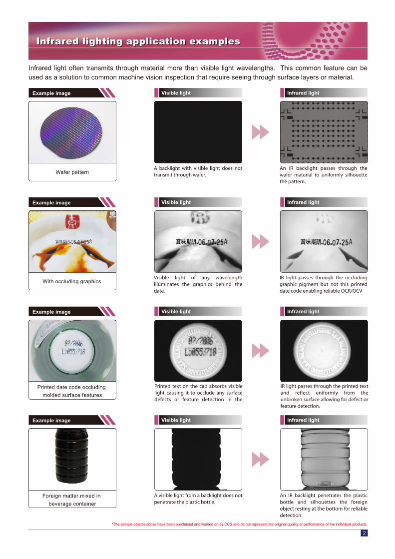
*The sample objects above have been purchased and worked on by CCS and do not represent the original quality or performance of the individual products.
Printed text on the cap absorbs visible light causing it to occlude any surface defects or feature detection in the
IR light passes through the printed text and reflect uniformly from the unbroken surface allowing for defect or feature detection.
Printed date code occluding
molded surface features
A visible light from a backlight does not penetrate the plastic bottle.
An IR backlight penetrates the plastic bottle and silhouettes the foreign object resting at the bottom for reliable detection.
Foreign matter mixed in
beverage container
Visible light of any wavelength illuminates the graphics behind the date.
IR light passes through the occluding graphic pigment but not this printed date code enabling reliable OCR/OCV
Visible light Infrared lightExample image
Example image
Example image
Example image
Visible light Infrared light
Visible light Infrared light
Visible light Infrared light
A backlight with visible light does not transmit through wafer.
An IR backlight passes through the wafer material to uniformly silhouette the pattern.
Wafer pattern
With occluding graphics
Infrared light often transmits through material more than visible light wavelengths. This common feature can be used as a solution to common machine vision inspection that require seeing through surface layers or material.
Infrared lighting application examplesInfrared lighting application examples
2
ModelPeak Wavelength
(nm)
12V/3.8W
12V/7.6W
12V/14W
12V/3.8W
12V/5.7W
12V/16W
12V/1.9W
12V/6.9W
50
130
170
80
90
270
40
80
1
2
3
4
5
6
7
8
Power Consumption
Weight (g) ModelPeak Wavelength
(nm)
LDR2-50IR850
LDR2-50IR940
LDL-82X15IR850
LDL-82X15IR940
LDR2-70IR850
LDR2-70IR940
LDL-130X15IR850
LDL-130X15IR940
LDR2-90IR850
LDR2-90IR940
LDL-180X16IR850
LDL-180X16IR940
SQR-56IR850
SQR-56IR940
LDQ-78IR850
LDQ-78IR940
LDR2-74IR850-LA
LDR2-74IR940-LA
LDQ-150IR850
LDQ-150IR940
LDR2-132IR850-LA
LDR2-132IR940-LA
LDL-100X100IR850
LDL-100X100IR940
LDL-42X15IR850
LDL-42X15IR940
LFL-100IR850
LFL-100IR940
LDL-74X27IR850
LDL-74X27IR940
850
940
850
940
850
940
850
940
850
940
850
940
850
940
850
940
LFV2-50IR850
LFV2-50IR940
850
940
850
940
850
940
850
940
850
940
850
940
850
940
850
940
Weight (g)Power
Consumption
9
10
11
12
13
14
15
16
Series
LED Color
Peak Wavelength(Typ.)
Viewing Angle
Input Voltage
Connector
Polarity, Signal
Cable Length
Case Material
Operating Conditions
Storage Conditions
Laser Class
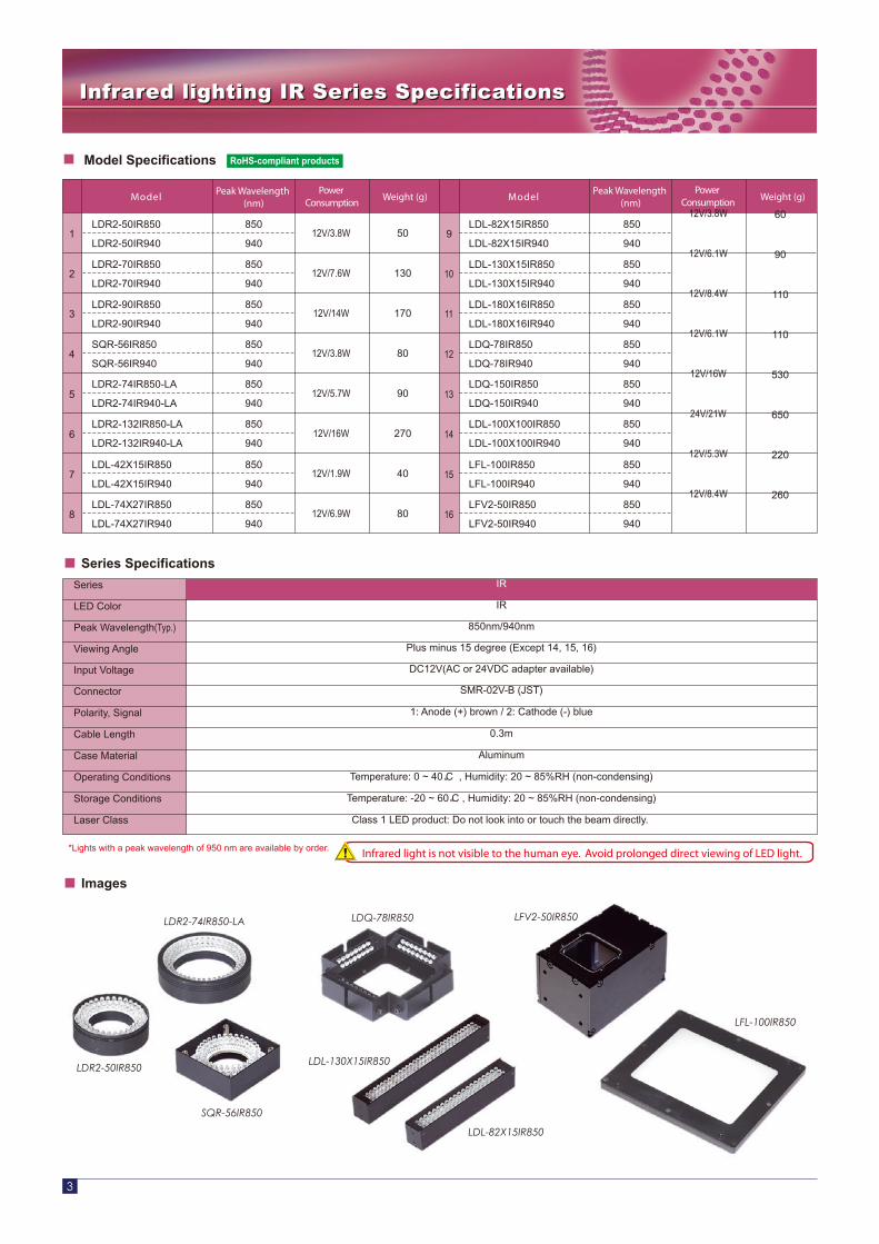
IR
IR
850nm/940nm
Plus minus 15 degree (Except 14, 15, 16)
DC12V(AC or 24VDC adapter available)
SMR-02V-B (JST)
1: Anode (+) brown / 2: Cathode (-) blue
0.3m
Aluminum
Temperature: 0 ~ 40 C , Humidity: 20 ~ 85%RH (non-condensing)
Temperature: -20 ~ 60 C , Humidity: 20 ~ 85%RH (non-condensing)
Class 1 LED product: Do not look into or touch the beam directly.
Series Specifications
Model Specifications
*Lights with a peak wavelength of 950 nm are available by order.
3
Infrared lighting IR Series SpecificationsInfrared lighting IR Series Specifications
Images
Infrared light is not visible to the human eye. Avoid prolonged direct viewing of LED light.
LDR2-74IR850-LA
LFL-100IR850
LFV2-50IR850
LDR2-50IR850
SQR-56IR850
LDQ-78IR850
LDL-130X15IR850
LDL-82X15IR850
12V/3.8W
12V/6.1W
12V/8.4W
12V/6.1W
12V/16W
24V/21W
12V/5.3W
12V/8.4W
60
90
110
110
530
650
220
260
RoHS-compliant products
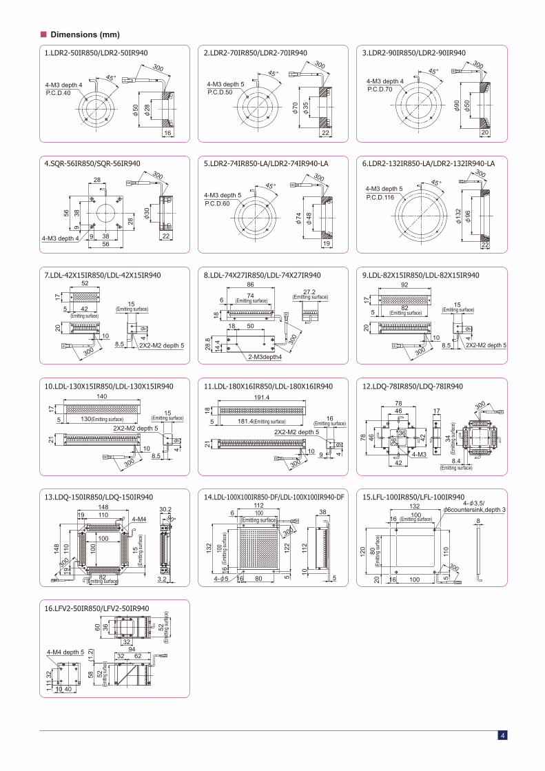
15.LFL-100IR850/LFL-100IR940
16.LFV2-50IR850/LFV2-50IR940
5.LDR2-74IR850-LA/LDR2-74IR940-LA 6.LDR2-132IR850-LA/LDR2-132IR940-LA
7.LDL-42X15IR850/LDL-42X15IR940 8.LDL-74X27IR850/LDL-74X27IR940 9.LDL-82X15IR850/LDL-82X15IR940
10.LDL-130X15IR850/LDL-130X15IR940 11.LDL-180X16IR850/LDL-180X16IR940 12.LDQ-78IR850/LDQ-78IR940
13.LDQ-150IR850/LDQ-150IR940 14.LDL-100X100IR850-DF/LDL-100X100IR940-DF
1.LDR2-50IR850/LDR2-50IR940 2.LDR2-70IR850/LDR2-70IR940 3.LDR2-90IR850/LDR2-90IR940
4.SQR-56IR850/SQR-56IR940
Dimensions (mm)
4
16
28
50
300
P.C.D.404-M3 depth 4
45
35
70
300
P.C.D.504-M3 depth 5
45
22
50
90
300
P.C.D.704-M3 depth 4
45
20
96
132
300
P.C.D.1164-M3 depth 5
45
22
48
74
300
P.C.D.604-M3 depth 5
45
19
30
300
4-M3 depth 4 229 3856
93856
28
28
42(Emitting surface)
2X2-M2 depth 5
15 (Emitting surface)
300
20
52
17
10
5
49
8.5
27.2 (Emitting surface)
2-M3depth4
300
6
86
1814
.4
28.8
18 50
74 (Emitting surface)
2X2-M2 depth 5300
82 (Emitting surface)
20
92
17
10
5
49
8.5
15 (Emitting surface)
16(Emitting surface)
2X2-M2 depth 5
300
181.4(Emitting surface)
191.4
5
18
10 49
9
21
2X2-M2 depth 5
300
130(Emitting surface)
140
17
10
5
49
8.5
21
15(Emitting surface)
15(E
mitt
ing
surfa
ce)
300
82(Emitting surface)
148
148
1911
0
19 1104-M4
100
100
30.2
3.2
90
34(E
mitt
ing
surfa
ce)
8.4(Emitting surface)
78
7846
42
36
36
46
17
4-M3
42
300
1011
2
512
2
1610
0(E
mitt
ing
surfa
ce)
132
38
516 80
6 100(Emitting surface)
112
4- 5
300
8
2080
(Em
ittin
g su
rface
)
120
511
0
16100
(Emitting surface)
132
16 100
300
111
32
10 40
58
32 6294
32
3660 52(E
mitt
ing
surfa
ce)
4-M4 depth 5
(1.2
)
52(E
mittin
g surf
ace)
52(E
mittin
g surf
ace)
4- 3.5/ 6countersink,depth 3
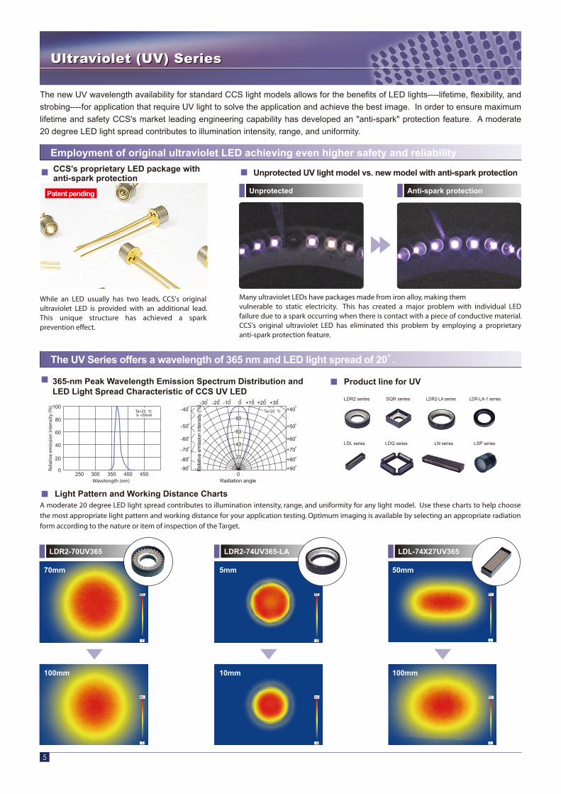
Many ultraviolet LEDs have packages made from iron alloy, making themvulnerable to static electricity. This has created a major problem with individual LED failure due to a spark occurring when there is contact with a piece of conductive material. CCS's original ultraviolet LED has eliminated this problem by employing a proprietary anti-spark protection feature.
While an LED usually has two leads, CCS's original ultraviolet LED is provided with an additional lead. This unique structure has achieved a spark prevention effect.
5
The new UV wavelength availability for standard CCS light models allows for the benefits of LED lights----lifetime, flexibility, and
strobing----for application that require UV light to solve the application and achieve the best image. In order to ensure maximum
lifetime and safety CCS's market leading engineering capability has developed an "anti-spark" protection feature. A moderate
20 degree LED light spread contributes to illumination intensity, range, and uniformity.
Ultraviolet (UV) Series Ultraviolet (UV) Series
CCS's proprietary LED package with anti-spark protection
Unprotected UV light model vs. new model with anti-spark protection
Employment of original ultraviolet LED achieving even higher safety and reliability
Light Pattern and Working Distance Charts
The UV Series offers a wavelength of 365 nm and LED light spread of 20 .
Unprotected Anti-spark protection
LDR2-70UV365
70mm
100mm
LDR2-74UV365-LA
5mm
10mm
LDL-74X27UV365
50mm
100mm
A moderate 20 degree LED light spread contributes to illumination intensity, range, and uniformity for any light model. Use these charts to help choose
the most appropriate light pattern and working distance for your application testing. Optimum imaging is available by selecting an appropriate radiation
form according to the nature or item of inspection of the Target.
Patent pending
0
-20 -10 -30 +20 +10 +30 0
2020
4040
6060
8080
-90
-80
-70
-60
-50
-40
+90
+80
+70
+60
+50
+40
Rel
ativ
e em
issi
on in
tens
ity (%
)
Radiation angle
Ta=25
450400350Wavelength (nm)
3002500
20
100
80
60
40
Rel
ativ
e em
issi
on
inte
nsi
ty (%
)
Ta=25 IF =20mA
365-nm Peak Wavelength Emission Spectrum Distribution and LED Light Spread Characteristic of CCS UV LED
LDR2 series SQR series LDR2-LA series LDR-LA-1 series
LDL series LDQ series LN series LSP series
Product line for UV

6
Ultraviolet light is most commonly used to cause materials such as inks or glues to fluoresce for identification or bonding integrity inspection. It also easily scatters off very small surface features such as scratches more so than longer wavelengths.
Ultraviolet lighting UV series application examplesUltraviolet lighting UV series application examples
Visible light does not illuminate the authenticity code used to identify high value items from imitations.
UV light shows the invisible bar code used to authenticate the merchandise origins.
Invisible Ink Authencitity Mark
Visible light penetrates the mat and does not provide sufficient contrast.
UV light reflects off the surfaces with high internal residual stress for reliable detection.
Dent on desk mat
Uniformly illuminating the bottom of can is very difficult to do with any wavelength of light.
UV light can be used to make an invisible ink fluoresce brightly for easy detecting that doesn't require even illumination of the background.
Visible light Ultraviolet lightExample image
Example image
Example image
Example image
Visible light Ultraviolet light
Visible light Ultraviolet light
Visible light Ultraviolet light
Visible light illuminates both the PCB features as well as foreign matter so they are difficult to distinguish.
UV light does scatters from the top layer of the board illuminates only the foreign particle but not the PCB trace pattern.
PCB foreign matter detection
Printed text on the
bottom of can

ModelPeak Wavelength
(nm)Weight (g)
Power Consumption
1
2
3
4
5
6
7
8
9
LDR2-50UV365
LDR2-70UV365
LDR2-32UV365
LDR2-42UV365
LDR2-90UV365
LDR2-90-30UV365
LDR2-120UV365
SQR-56UV365
LDR2-74UV365-LA
LDR2-100UV365-LA
LDR2-132UV365-LA
LDR2-170UV365-LA
LDR2-208UV365-LA
LDR-75-UV365-LA-1
LDR-96-UV365-LA-1
LDR-146-UV365-LA-1
365 365
10
11
12
13
14
15
16
24V/0.4W
24V/0.8W
24V/1.2W
24V/3.1W
24V/3.8W
24V/6.1W
24V/9.5W
24V/1.6W
24V/1.9W
24V/4.6W
24V/6.9W
24V/9.9W
24V/12W
24V/1.6W
24V/2.3W
24V/3.1W
30
50
50
130
170
220
510
80
90
170
270
350
380
70
100
160
200
220
15
30
95
45
85
110
60
100
330
490
790
400
115
Model Peak Wavelength (nm)
Weight (g)Power Consumption
17
18
19
20
21
22
23
24
25
LDL-34X8UV365
LDL-42X15UV365
LDR-176-UV365-LA-1
LDR-206-UV365-LA-1
LDL-74X27UV365
LDL-82X15UV365
LDL-130X15UV365
LDL-180X16UV365
LDQ-60-25UV365
LDQ-78UV365
LDQ-100UV365
LDQ-150UV365
LDQ-200UV365
LN-200UV365
LSP-41UV365
26
27
28
29
30
31
24V/3.8W
24V/4.6W
24V/0.4W
24V/0.8W
24V/3.1W
24V/1.6W
24V/2.3W
24V/3.8W
24V/1.6W
24V/1.6W
24V/3.1W
24V/6.1W
24V/9.1W
24V/1.9W
24V/1.2W
Series
LED Color
Peak Wavelength (Typ.)
Viewing Angle
Input Voltage
Connector
Polarity, Signal
Cable Length
Case Material
Operating Conditions
Storage Conditions
Laser Class
UV
Ultraviolet
365 nm
Plus minus 20 degree.
24 VDC
SMR-03V-B (JST)
1: Anode (+) brown / 2: NC / 3: Cathode (-) blue
0.3 m
Aluminum
Temperature: 0 ~ 40 C, Humidity: 20 ~ 85%RH (non-condensing)
Temperature: -20 ~ 60 C, Humidity: 20 ~ 85%RH (non-condensing)
Class 3B LED product: Do not look into or touch the beam directly.
Series Specifications
Model Specifications
7
Ultraviolet lighting UV Series SpecificationsUltraviolet lighting UV Series Specifications
LDR2-90UV365
LDL-82X15UV365
LDR2-74UV365-LA
LDR-75UV365-LA-1LDR2-32UV365
LDR2-50UV365
LDR2-100UV365-LALDQ-100UV365
LDL-42X15UV365
LSP-41UV365
Images
RoHS-compliant products
The UV Series ultraviolet lighting products use a laser beam equivalent to Class 3B. Direct incidence of ultraviolet light into the eye is extremely dangerous. Be sure to put on UV protective glasses when using the product and exercise caution in its handling. Ensure safety with the device or equipment on which to mount the lighting.
1.LDR2-32UV365 2.LDR2-42UV365 3.LDR2-50UV365
4.LDR2-70UV365 5.LDR2-90UV365 6.LDR2-90-30UV365
7.LDR2-120UV365 8.SQR-56UV365 9.LDR2-74UV365-LA
10.LDR2-100UV365-LA 11.LDR2-132UV365-LA 12.LDR2-170UV365-LA
13.LDR2-208UV365-LA 14.LDR-75-UV365-LA-1 15.LDR-96-UV365-LA-1
16.LDR-146-UV365-LA-1 17.LDR-176-UV365-LA-1 18.LDR-206-UV365-LA-1
8
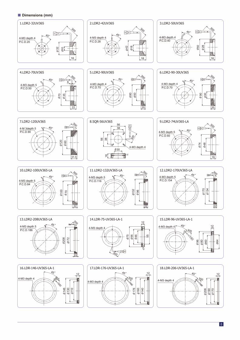
Dimensions (mm)
32 10
16
300
4-M3 depth 445
P.C.D.20
18
42
18
300
P.C.D.284-M3 depth 4
45
16
28
50
300
P.C.D.404-M3 depth 4
45
90
30
20
4-M3 depth 4
300
P.C.D.70
45
20
50
90
4-M3 depth 4
300
P.C.D.70
45
22
70
35
4-M3 depth 5
300
P.C.D.50
45 6
48
74
19
30045 4-M3 depth 5
P.C.D.60
4-M3 depth 430
300
5638
56 3818
60
120
31.5
4-M 3depth 5
300
P.C.D.90
45
22 1
34
170
4-M3 depth 545
P.C.D.154
300
60
64
80
96
4-M3 depth 4 1245 300
46
75
56
4-M3 depth 4
300
12
55
208
172
22
4-M3 depth 545
P.C.D.186
300
130
110
146
4-M3 depth 4 300
1245
160
140
176
4-M3 depth 4
45 300
12 45
4-M3 depth 4300
190
170
206
12
100
70
22
300
4-M3 depth 5P.C.D.84
45
96
132
22
4-M3 depth 5
30045
P.C.D.116
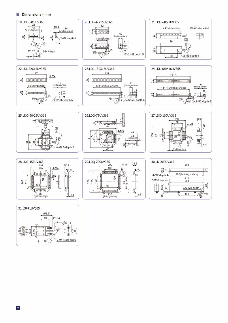
19.LDL-34X8UV365 20.LDL-42X15UV365 21.LDL-74X27UV365
22.LDL-82X15UV365 23.LDL-130X15UV365 24.LDL-180X16UV365
25.LDQ-60-25UV365 26.LDQ-78UV365 27.LDQ-100UV365
28.LDQ-150UV365 29.LDQ-200UV365 30.LN-200UV365
31.LSP41UV365
9
Dimensions (mm)
34(Emitting surface)
8.4(Emitting surface)
2-M2 depth 5
2-M3 depth 4
5 5
10.444
815
20
5
1212
300
42(Emitting surface)
2X2-M2 depth 5
15(Emitting surface)
49
7
20
52
17
10
300
74(Emitting surface) 27.2(Emitting surface)
2-M3 depth 4
18
50
28.8
86
300
181.4(Emitting surface)16
(Emitting surface)
2X2-M2 depth 5
18
191.4
21
49
8
21
10
300
42(E
mitt
ing
surfa
ce)
15(Emitting surface)
300
90
108
108 60
60
30.270
70
4-M4
3.2
2-M3(Fixing screw)
2X2-M3 depth 7
16
200(Emitting surface)4-M2 depth 4210
20
205
205
100 300
25
1524.5
45.6
(8)
10
2X2-M2 depth 5
15(Emitting surface)130(Emitting surface)
49
8
21
140
17
300
10
34(Emitting surface)
4-M3
78
78
17
46
42
36
36
42
44
10
5 5
300
8.4
(Em
ittin
g su
rface
)8.
4(E
mitt
ing
surfa
ce)
130(Emitting surface)
8-M4
15(E
mitt
ing
surfa
ce)
90
200
200 15
0
150
31.2
100
175
3.2
100
300
82(Emitting surface)
2X2-M2 depth 5
15(Emitting surface)
92
17
10
20
49
300
7
2-M2
4-M2.6 depth 3
58
58 2512
25
30
30
30
30
300
82(Emitting surface)
15(E
mitt
ing
surfa
ce)
90
148
148 10
0
100
30.2110
110
4-M4
300
3.2
41
33(E
mitt
ing
surfa
ce)
300
2-M4 Fixing screw
(51.5)
40 (11.5)
82 36 2
26
12

Without either filter, both
ultraviolet and visible light
are captured, which causes
reduced contrast.
Use of an ultraviolet transmission
filter allows capturing of only the
components in the ultraviolet
region.
Use of an ultraviolet cutting
filter allows capturing of only
the visible light components
from scattered light.
Images with/without ultraviolet transmission/Ultraviolet cutting filter
Ultraviolet transmission filter U-340series
U340-25U340-27U340-30U340-40U340-46
M25.5 P0.5M27.0 P0.5M30.5 P0.5M40.5 P0.5M46.0 P0.75
Ultraviolet cutting filterL-42series
L42-25L42-27L42-30L42-40L42-46
M25.5 P0.5M27.0 P0.5M30.5 P0.5M40.5 P0.5M46.0 P0.75 Wavelength (nm)
300 400 500 600 700 8000
20
100
80
60
40
Tran
smis
sio
n (%
)
U-340 filter
L-42 filter
365 nm UV LED emission spectrum distribution
Filter characteristic vs. UV LED emission spectrum distribution
For safe use
In 1993, the International Electrotechnical Commission (IEC) made effective IEC 825-1, a standard concerning the safety of laser products, the scope of which
includes LEDs. Subsequently, relaxation of provisions was considered for diffusive light sources and IEC 60825-1 Edition 1.1 of 1998 introduced methods of
measurement with the sizes of light sources taken into account. Later in 2001, IEC 60825-1 Amendment 2 provided for the division of laser into seven classes.
The laser used in CCS's ultraviolet LED lighting products corresponds to Class 3B. Never allow any direct or diffusely reflective ultraviolet beam radiate on the
eye or skin. Directly looking into the light source may affect the health of the eye. Be sure to wear UV protective glasses when using the product and exercise
caution in its handling. Regarding the device or equipment on which to mount the lighting, provide warning indication stating the use of ultraviolet lighting and
ensure safety. See the "Ultraviolet LED Lighting Instruction Manual" for details.
About camera, lens and filter
The image taken may be affected by the emission spectrum distribution of the ultraviolet LED used and the spectral sensitivity characteristic of the
CCD camera. For stable imaging, optimize the optical system including a CCD camera, lens and filter.
400 420 440380360
Wavelength (nm)
3403200
20
100
80
60
40
Rel
ativ
e se
nsi
tivi
ty
CCD camera spectral sensitivity characteristic vs.
UV LED emission spectrum distribution
CCD camera spectral sensitivity characteristic
365 nm UV LED emission spectrum distribution
*Graphic representing spectral sensitivity characteristic of CCD camera XC-EU50 provided by Sony Corp.
For optimum imaging with ultraviolet lighting, use a CCD camera that is sensitive in the
near-ultraviolet region. Ordinary CCD cameras are not very sensitive in the near-ultraviolet
region, which may cause images to be darker or susceptible to disturbance light. Use of
ultraviolet transmitting filters or ultraviolet cutting filters reduces the light intensity. Allow
sufficient margins in the imaging conditions (lighting control, f-stop number, distance
between the work and camera, distance between the work and lighting, etc.) when using
such filters.
UV protective glasses*
Imaging of mail code
10
Option
Notes on use of ultraviolet lighting
Without filter With UV transmission filter With UV cutting filterWork image
Model Size
Model Size
Caution
- Never directly look into or touch the ultraviolet beam.
- Before turning the light on, be sure to put on UV protective glasses and prevent the light from entering the eye.
- Do not turn the light on of the ultraviolet LED as the radiating (light emitting) section is directed at the human eye.
- Wear long-sleeved clothes and gloves to prevent exposure of the skin for preventing the ultraviolet light from reaching the skin.
- Be sure to inform all personnel involved in the use of the product or with access to the surrounding areas of the danger of ultraviolet LED.
Make sure of the wavelength range for which the glasses provide protection.
*
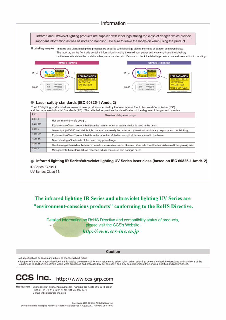
Infrared lighting IR Series/ultraviolet lighting UV Series laser class (based on IEC 60825-1 Amdt. 2)
IR Series: Class 1
UV Series: Class 3B
Laser safety standards (IEC 60825-1 Amdt. 2) The LED lighting products fall in classes of laser products specified by the International Electrotechnical Commission (IEC) and the Japanese Industrial Standards (JIS). The table below provides the classification of the degrees of danger and overview.
Overview of degree of danger
Has an inherently safe design.
Equivalent to Class 1 except that it can be harmful when an optical device is used in the beam.
Low-output (400-700 nm) visible light; the eye can usually be protected by a natural involuntary response such as blinking.
Equivalent to Class 2 except that it can be more harmful when an optical device is used in the beam.
Direct viewing of the inside of the beam may pose danger.
Direct viewing of the inside of the beam is hazardous in normal conditions. However, diffuse reflection of the beam is believed to be generally safe.
May generate hazardous diffuse reflection, which can cause skin damage or fire.
Class
Class 1
Class 1M
Class 2
Class 2M
Class 3R
Class 3B
Class 4
Label tag samples Infrared and ultraviolet lighting products are supplied with label tags stating the class of danger, as shown below.
The label tag on the front side contains information including the maximum power and wavelength and the label tag
on the rear side states the model number, serial number, etc. Be sure to check the label tags before use and use caution in handling.
Infrared and ultraviolet lighting products are supplied with label tags stating the class of danger, which provide
important information as well as notes on handling. Be sure to leave the labels on when using the product.
Front
Rear
Information
Infrared lighting Ultraviolet lighting
LED RADIATION
AVOID EXPOSURE TO BEAMMAX POWER:500mWWAVE LENGTH:365nm
CLASS 3B LED PRODUCT
FrontLED RADIATION
AVOID EXPOSURE TO BEAM
CLASS 3B LED PRODUCT
MAX POWER:500mWWAVE LENGTH:365nm
RearLDR2-32UV365
1002639-01234524V/0.4W
MADE IN JAPAN
EN60825-1:1994+A1:2002+A2:2001
EN60825-1:1994+A1:2002+A2:2001
LDR2-50IR8501002578-012345
12V/3.8WMADE IN JAPAN
LED RADIATION
DO NOT STARE INTO BEAMMAX POWER:47mWWAVE LENGTH:850nm
CLASS 1 LED PRODUCTEN60825-1:1994+A1:2002+A2:2001
DO NOT STARE INTO BEAM
CLASS 2 LED PRODUCT
MAX POWER:47mWWAVE LENGTH:850nm
Samples of the work images described in this catalog are referential for our customers to select lights. When selecting, be sure to check the functions and conditions of the equipment. In addition, the sample works were purchased and processed by our company, and they do not represent their original qualities and performances.
All specifications or design are subject to change without notice
Caution
--
Detailed information on RoHS Directive and compatibility status of products, please visit the CCS's Website.
The infrared lighting IR Series and ultraviolet lighting UV Series are
"environment-conscious products" conforming to the RoHS Directive.
http://www.ccs-inc.co.jp
LED RADIATION
EN60825-1:1994+A1:2002+A2:2001
http://www.ccs-grp.comHeadquarters Shimodachiuri-agaru, Karasuma-dori, Kamigyo-ku, Kyoto 602-8011 Japan
Phone: +81-75-415-8284 / Fax: +81-75-415-8278E-mail: [email protected]
Copyright(c) 2007 CCS Inc. All Rights Reserved.Descriptions in this catalog are based on the information available as of August 2007. 02002-02-0610-IR/UV


![Dimensions: [mm] Recommended Land Pattern: [mm] Absolute ... · Electrical & Optical Properties: Properties Test conditions Value Unit min. typ. max. Peak Wavelength (Blue) λ Peak](https://img.pdfslide.us/doc/110x75/612f3b351ecc515869434f2b/dimensions-mm-recommended-land-pattern-mm-absolute-electrical-optical.jpg)


![Dimensions: [mm] Recommended Land Pattern: [mm ......Electrical & Optical Properties: Properties Test conditions Value Unit min. typ. max. Peak Wavelength (Red) λ Peak R 5 mA 625](https://img.pdfslide.us/doc/110x75/614a7c9012c9616cbc69726a/dimensions-mm-recommended-land-pattern-mm-electrical-optical.jpg)