Embed Size (px)
Citation preview
Subsurface Exploration and Geotechnical Engineering Report
Prepared for:
Ridgetop Engineering and Consulting Services
5255 Ronald Reagan Blvd, Suite 210
Johnstown, CO 80534
North Range Storage Tank
Cheyenne, Wyoming
September 21, 2016
18845-HX
Prepared by:
INBERG-MILLER ENGINEERS
350 Parsley Boulevard
Cheyenne, WY 82007
INBERG-MILLER ENGINEERS Quality Solutions Through Teamwork
i
124 East Main Street
Riverton, WY 82501
307-856-8136
307-856-3851 (fax)
1120 East “C” Street
Casper, WY 82601
307-577-0806
307-856-3851 (fax)
350 Parsley Boulevard
Cheyenne, WY 82007
307-635-6827
307-856-3851 (fax)
816 West Spruce St.
Rawlins, WY 82301
307-856-8136
307-856-3851 (fax)
830 E. Richards, Suite 1
Douglas, WY 82633
307-359-7000
307-856-3851 (fax)
193 W. Flaming Gorge Way
Green River, WY 82935
307-875-4394
307-856-3851 (fax)
September 21, 2016 18845-HX
Mr. Mike Beach Ridgetop Engineering and Consulting Services 5255 Ronald Reagan Blvd, Suite 210 Johnstown, CO 80534 RE: SUBSURFACE EXPLORATION AND GEOTECHNICAL ENGINEERING REPORT NORTH RANGE STORAGE TANK CHEYENNE, WYOMING
Dear Mr. Beach:
Enclosed is a PDF copy of our Subsurface Exploration and Geotechnical Engineering report for the above-referenced project. The work described in this report has been completed in accordance with our Amendments 2 and 3 dated June 16, 2016 and June 20, 2016, respectively, to our December 15, 2015 Work or Service Contract .
It has been a pleasure participating in this project. We are available to provide additional services at
your request. Services we could provide include:
additional field exploration
environmental assessment
civil engineering
plan and specification review
surveying
construction materials testing
observation of excavations and earthwork
If you have any questions or comments, please contact us at 307-635-6827.
Sincerely,
INBERG-MILLER ENGINEERS
Derek J. Baker, P.E., P.G.
Vice President
DJB:cno\\\IME01\Projects\18845-HX RIDGETOP ENGINEERING North Range Storage
Tank\Geotech\18845-HX rpt.docx
Ridgetop Engineering and Consulting Services / North Range Storage Tank 18845-HX
INBERG-MILLER ENGINEERS ii September 21, 2016
TABLE OF CONTENTS
TRANSMITTAL LETTER .................................................................................................................................... i
TABLE OF CONTENTS ..................................................................................................................................... ii
SUMMARY ..................................................................................................................................................... 1
SCOPE OF SERVICES ...................................................................................................................................... 1
PROJECT INFORMATION ............................................................................................................................... 1
FIELD EXPLORATION ...................................................................................................................................... 1
LABORATORY TESTING PROGRAM ................................................................................................................ 2
SITE CONDITIONS .......................................................................................................................................... 2
SUBSOIL CONDITIONS ................................................................................................................................... 3
GROUNDWATER CONDITIONS ...................................................................................................................... 3
RECOMMENDATIONS ................................................................................................................................... 4
EARTHWORK ........................................................................................................................................... 4
FOUNDATIONS .............................................................................................................................................. 5
TANK BOTTOM ....................................................................................................................................... 6
RING WALL .............................................................................................................................................. 6
ESTIMATED TANK SETTLEMENT ............................................................................................................. 7
LATERAL EARTH PRESSURES ................................................................................................................... 7
GENERAL ................................................................................................................................................. 8
CONSTRUCTION CONSIDERATIONS .............................................................................................................. 9
CLOSURE ....................................................................................................................................................... 9
APPENDIX A – SITE INFORMATION
Site Location Map
Site Observations
Test Boring Location Plan
APPENDIX B – TEST BORING INFORMATION
Test Boring Logs
General Notes
Classification of Soils for Engineering Purposes
APPENDIX C – LABORATORY TEST RESULTS
Particle Size Analysis
Consolidation-Swell Test
APPENDIX D – ADDITIONAL INFORMATION
Limitations and Use of This Report
Sample and Data Collection Information
Important Information About Your Geotechnical Engineering Report
Ridgetop Engineering and Consulting Services / North Range Storage Tank 18845-HX
INBERG-MILLER ENGINEERS 1 September 21, 2016
SUMMARY
Based on information obtained from our subsurface exploration and laboratory testing of recovered
samples, it is our opinion that the site is suitable for construction of the proposed North Range Storage
Tank project, subject to considerations for site preparation and foundations, which are described in this
report. Our field exploration included 4 test borings to depths of 26.5 to 76.5 feet. Soils encountered
generally include unconsolidated clayey sands and sandy clays in varying combinations and thicknesses
overlying weathered to competent sedimentary bedrock. Soils at anticipated shallow foundation depths
were generally in a medium dense to dense condition. Groundwater was encountered at a depth of 44
feet below ground surface during drilling operations.
The proposed tank can be supported on a conventional ring wall footing bearing on properly prepared
and compacted native subgrades. Footings can be placed on firm, native soil subgrades that have been
scarified, moisture conditioned, and compacted as described in the recommendations. In order to
reduce total and differential settlement below the tank floor, we recommend that the tank floor be
supported on compacted fill equal to the depth of the ring wall footings. Excavated site soils are suitable
for use as fill beneath the tank floor.
SCOPE OF SERVICES
The purpose of this study was to explore subsurface conditions at the site of the proposed Cheyenne
North Range Storage Tank, and to provide geotechnical recommendations for design and construction.
Specific recommendations and information are provided about foundation types, bearing capacity,
groundwater conditions, consolidation-swell potential of foundation soils, earthwork, and other
pertinent foundation and construction requirements.
PROJECT INFORMATION
Project information was provided by Mike Beach with Ridgetop Engineering and Consulting Services. It is
our understanding the project will consist of the construction of one water storage tank and a control
building. The tank will be 110 feet in diameter and 45 feet tall.
Detailed information on the structural loads was not available at the time this report was prepared.
However, based on information provided, we assume that the tank will have wall loads on the order of 2
to 3 kips per linear foot. We anticipate tank floor loads will be approximately 2,800 psf. Some
recommendations provided in this report will not be appropriate for tanks with loads in excess of those
described above.
Grading plans were not provided to us at the time this report was prepared. We assume that some
minor grading will be required and cut and fill depths will be less than 3 feet. If cuts and fills significantly
in excess of these assumptions are planned, we should be provided plans and the recommendations of
this report should be reviewed for conformance with the planned site configuration.
FIELD EXPLORATION
The fieldwork was performed using a CME 85 truck-mounted drilling rig at the site August 29-30, 2016.
Four test borings were advanced to depths of 26.5 to 76.5 feet. Drilling was performed using 3.25-inch
inside diameter, hollow-stem augers. The augers act as a continuously advancing, steel casing. The
Ridgetop Engineering and Consulting Services / North Range Storage Tank 18845-HX
INBERG-MILLER ENGINEERS 2 September 21, 2016
method prevents test holes from caving in above the levels to be tested. Sampling tools are lowered
inside the hollow-stem for testing into undisturbed soils.
Drilling and field sampling were performed according to the following standard specifications:
1. “Standard Practice for Using Hollow-Stem Augers for Geotechnical Exploration and Soil
Sampling,” ASTM D6151.
2. Sampling with a 2-inch O.D., split-barrel (split-spoon) sampler per ASTM D1586, “Penetration
Test and Split-Barrel Sampling of Soils.” Thirty-five such tests were performed. Standard
penetration test blow counts were obtained by driving a 2.0-inch-diameter split-spoon sampler
into the soil using an automatic hammer that drops a 140-pound hammer a distance of 30
inches. The SPT N-value is the blow count for 12 inches of sampler penetration. N-values are
correlated to soil relative density, hardness, strength and a variety of other parameters.
3. Sampling with a 2.5-inch I.D., thick-wall, ring-lined, split-barrel, drive sampler per ASTM D3550.
Seven such samples were obtained.
The soil samples were field classified by the geological engineer, sealed in containers to prevent loss of
moisture, and returned to our laboratory. A field log was prepared for each boring during drilling. The
borings were located in the field by use of handheld GPS with coordinates. Test boring elevations were
interpolated from the topographic map with 1-foot contour intervals. The topographic map of the site
was prepared and provided by Ridgetop Engineering and Consulting Services.
LABORATORY TESTING PROGRAM
Upon return to the office, samples were classified visually in accordance with ASTM D2488. In order to
better classify the recovered samples and determine their engineering properties, the following
laboratory soil tests were performed:
TESTS
1. Moisture Content (ASTM D2216) 41
2. Atterberg Limits (ASTM D4318) 3
3. Sieve Analysis (#4 to #200) (ASTM C136 and C117) 3
4. Water Soluble Sulfate 2
5. Consolidation-Swell Test (ASTM D2435) 2
A final log for each boring was prepared containing the work method, samples recovered, and a
description of soils encountered. The sieve analyses and consolidation-swell tests are presented
graphically in Appendix C. All other test results are arrayed on the final logs bound into Appendix B.
SITE CONDITIONS
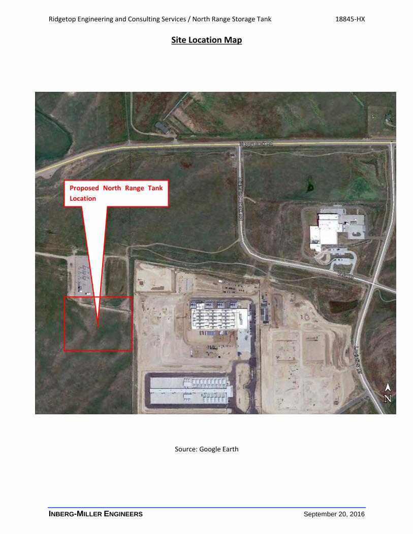
The site is located south of Happy Jack Road, and directly west of the existing Microsoft Data Center in
Cheyenne, Wyoming. The topography at the site slopes down to the west, with approximately 4 feet of
relief from the northeast down to the southwest. A site location map, site observation sheet, and test
boring location plan in Appendix A describe the site in more detail.
Ridgetop Engineering and Consulting Services / North Range Storage Tank 18845-HX
INBERG-MILLER ENGINEERS 3 September 21, 2016
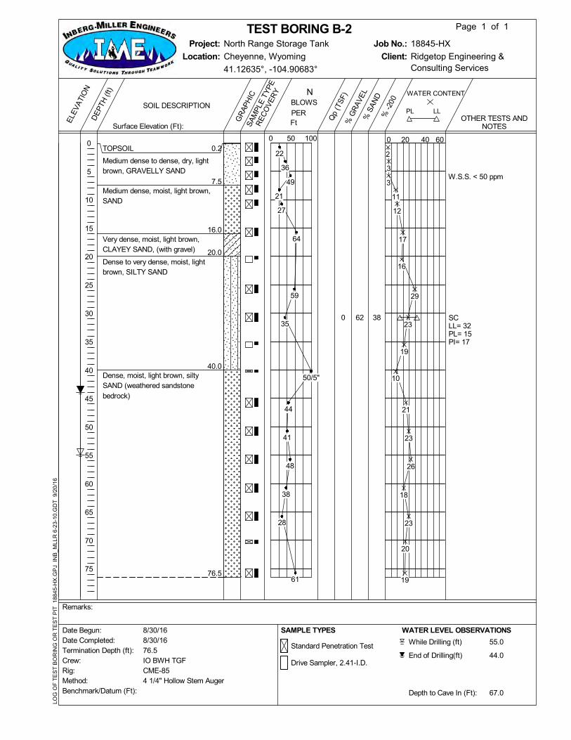
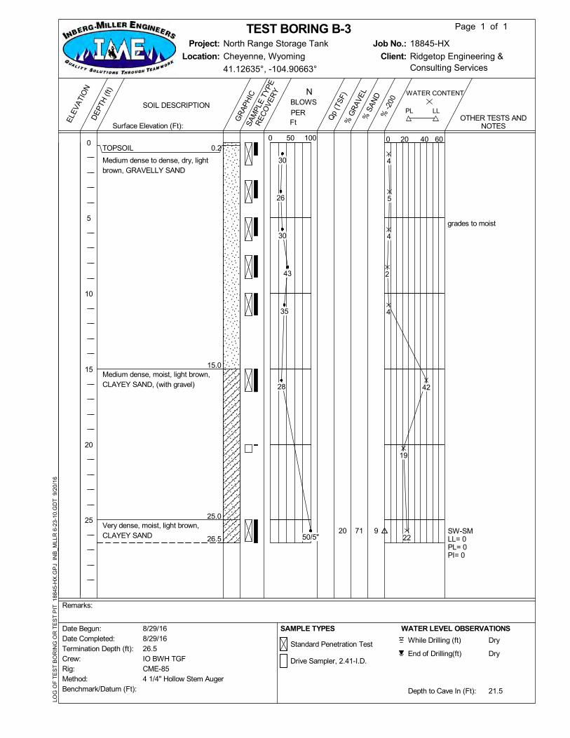
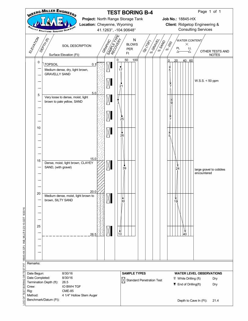
SUBSOIL CONDITIONS
The subsoil classified in the 4 test borings performed at the site generally consists of unconsolidated
sand, gravelly sand, and clayey sands in varying quality, particle size and thicknesses, overlying
weathered to competent sedimentary bedrock.
The topsoil consists of 0 to 0.2 feet of silty, fine to medium sand. The organic content of the soils
appears to be relatively low. Standard Penetration Test Blow counts (N-Values) indicate that the soils
are in a very loose to medium dense condition.
Over the approximate interval of 0.2 feet to approximately 40 feet, overburden generally consisting of
sand, gravelly sand, and clayey sand in varying relative percentages and thicknesses were encountered.
Laboratory testing indicates minus number 200 sieve fractions of 12 percent to 38 percent and plasticity
indexes of 0 to 17 percent indicating non plastic to medium plasticity. Standard Penetration Test blow
counts (N-values) indicate that the soil has medium dense to very dense relative density.
Soils become increasingly denser and more cemented with depth. Below depths of approximately 40
feet, soils are slightly to moderately cemented. This layer is probably weathered Ogallala Formation
sedimentary bedrock. However, the material properties of this transitional soil-bedrock layer are more
similar to soil than to rock, and for the purpose of this report can be considered as dense to very dense
soil. One test borings were terminated in the Ogallala Formation. The surface of the bedrock is not
distinct due to apparent weathering and a zone of residual soil derived from the bedrock that has
formed at the lower portion of the unconsolidated overburden. Sedimentary bedrock has moderate to
high strength and low compressibility.
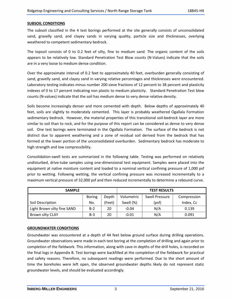
Consolidation-swell tests are summarized in the following table. Testing was performed on relatively
undisturbed, drive-tube samples using one-dimensional test equipment. Samples were placed into the
equipment at native moisture content and loaded to a nominal vertical confining pressure of 1,000 psf
prior to wetting. Following wetting, the vertical confining pressure was increased incrementally to a
maximum vertical pressure of 32,000 psf and then reduced incrementally to determine a rebound curve.
SAMPLE TEST RESULTS
Soil Description
Boring
No.
Depth
(Feet)
Volumetric
Swell (%)
Swell Pressure
(psf)
Compression
Index, Cc
Light Brown silty fine SAND B-2 20 -0.04 N/A 0.139
Brown silty CLAY B-3 20 -0.01 N/A 0.091
GROUNDWATER CONDITIONS
Groundwater was encountered at a depth of 44 feet below ground surface during drilling operations.
Groundwater observations were made in each test boring at the completion of drilling and again prior to
completion of the fieldwork. This information, along with cave-in depths of the drill holes, is recorded on
the final logs in Appendix B. Test borings were backfilled at the completion of the fieldwork for practical
and safety reasons. Therefore, no subsequent readings were performed. Due to the short amount of
time the boreholes were left open, the observed groundwater depths likely do not represent static
groundwater levels, and should be evaluated accordingly.
Ridgetop Engineering and Consulting Services / North Range Storage Tank 18845-HX
INBERG-MILLER ENGINEERS 4 September 21, 2016
Groundwater conditions could change with seasonal or long-term changes in climatic conditions and
post-construction changes in irrigation and surface water runoff. Generally, developed sites have a
significantly greater volume of water available to percolate into the ground due to storm water runoff
from hard surfaces. Localized, perched groundwater tables may develop above clay layers or within the
foundation backfill zone.
RECOMMENDATIONS
EARTHWORK
1. Prior to construction on the site, all vegetation and organic surface matter should be stripped
from the surface. Based on the test borings, and on-going earthwork operations, it appears that
little to no additional stripping will be required.
2. Demolition of existing structures and utilities (if any) must include complete removal of below
grade piping, concrete and old fill.
3. After excavation to desired site grades (including any overexcavation required), and prior to
placing fill or erection of forms for foundations and slabs, we recommend the site surface be
compacted. This compaction densifies the native subgrade and soils loosened by excavation.
This compaction effort should be performed in the presence of the Geotechnical Engineer so
that soft or loose zones can be properly identified and improved. Alternatively, the Geotechnical
Engineer can observe proof rolling with a heavily-loaded wheeled vehicle. If loose or soft zones
are encountered that do not improve with repeated compaction, they should be removed and
replaced with properly compacted, approved fill, as described in Item 5 below.
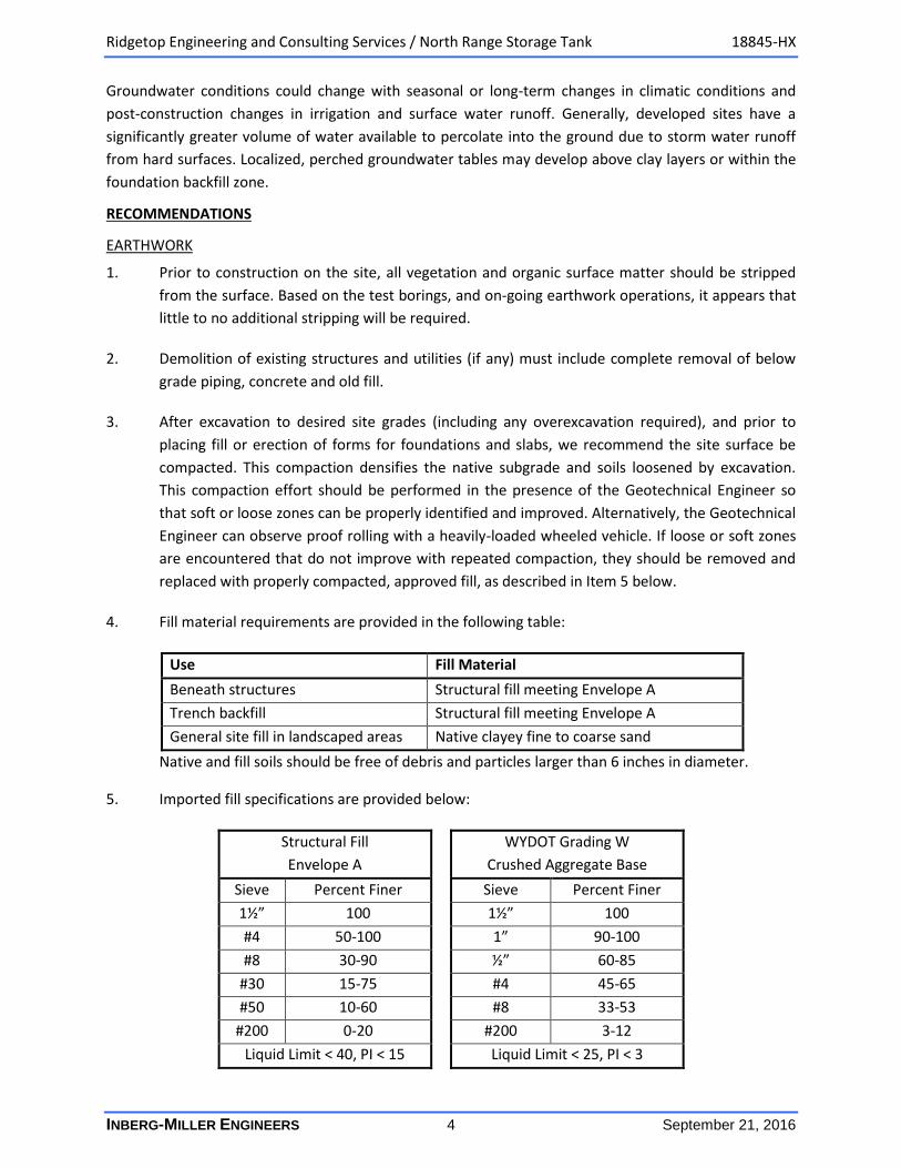
4. Fill material requirements are provided in the following table:
Use Fill Material
Beneath structures Structural fill meeting Envelope A
Trench backfill Structural fill meeting Envelope A
General site fill in landscaped areas Native clayey fine to coarse sand
Native and fill soils should be free of debris and particles larger than 6 inches in diameter.
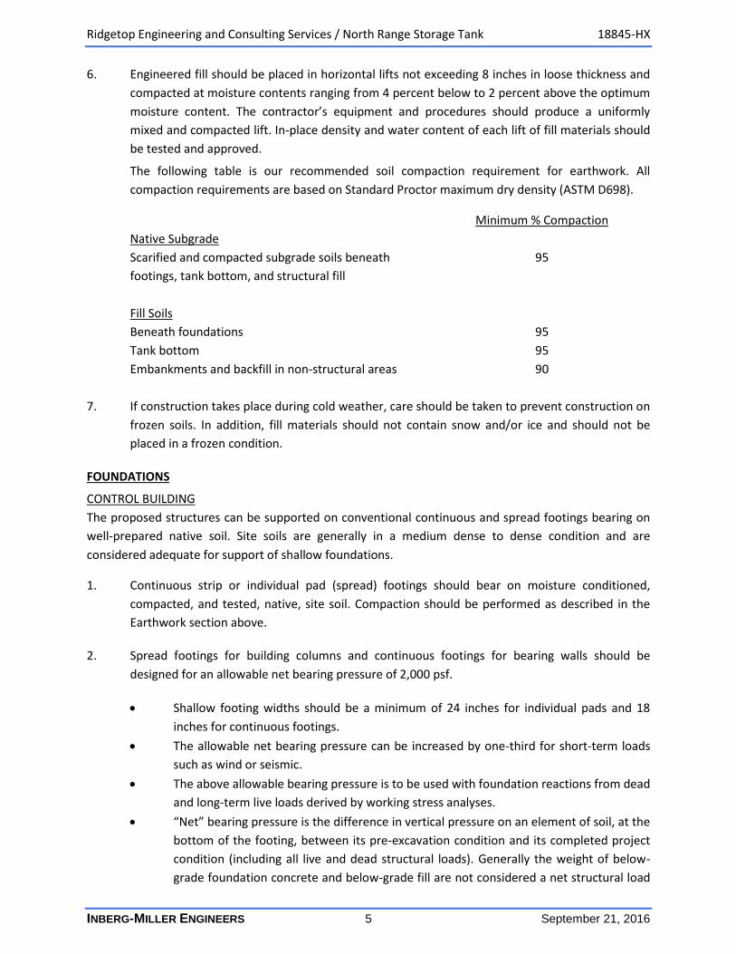
5. Imported fill specifications are provided below:
Structural Fill
Envelope A
WYDOT Grading W
Crushed Aggregate Base
Sieve Percent Finer Sieve Percent Finer
1½” 100 1½” 100
#4 50-100 1” 90-100
#8 30-90 ½” 60-85
#30 15-75 #4 45-65
#50 10-60 #8 33-53
#200 0-20 #200 3-12
Liquid Limit < 40, PI < 15 Liquid Limit < 25, PI < 3
Ridgetop Engineering and Consulting Services / North Range Storage Tank 18845-HX
INBERG-MILLER ENGINEERS 5 September 21, 2016
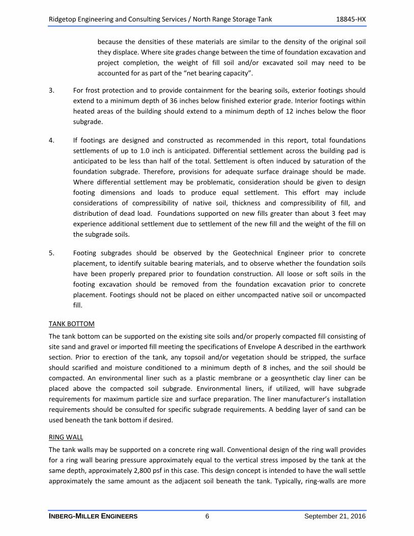
6. Engineered fill should be placed in horizontal lifts not exceeding 8 inches in loose thickness and
compacted at moisture contents ranging from 4 percent below to 2 percent above the optimum
moisture content. The contractor’s equipment and procedures should produce a uniformly
mixed and compacted lift. In-place density and water content of each lift of fill materials should
be tested and approved.
The following table is our recommended soil compaction requirement for earthwork. All
compaction requirements are based on Standard Proctor maximum dry density (ASTM D698).
Minimum % Compaction
Native Subgrade
Scarified and compacted subgrade soils beneath 95
footings, tank bottom, and structural fill
Fill Soils
Beneath foundations 95
Tank bottom 95
Embankments and backfill in non-structural areas 90
7. If construction takes place during cold weather, care should be taken to prevent construction on
frozen soils. In addition, fill materials should not contain snow and/or ice and should not be
placed in a frozen condition.
FOUNDATIONS
CONTROL BUILDING
The proposed structures can be supported on conventional continuous and spread footings bearing on
well-prepared native soil. Site soils are generally in a medium dense to dense condition and are
considered adequate for support of shallow foundations.
1. Continuous strip or individual pad (spread) footings should bear on moisture conditioned,
compacted, and tested, native, site soil. Compaction should be performed as described in the
Earthwork section above.
2. Spread footings for building columns and continuous footings for bearing walls should be
designed for an allowable net bearing pressure of 2,000 psf.
Shallow footing widths should be a minimum of 24 inches for individual pads and 18
inches for continuous footings.
The allowable net bearing pressure can be increased by one-third for short-term loads
such as wind or seismic.
The above allowable bearing pressure is to be used with foundation reactions from dead
and long-term live loads derived by working stress analyses.
“Net” bearing pressure is the difference in vertical pressure on an element of soil, at the
bottom of the footing, between its pre-excavation condition and its completed project
condition (including all live and dead structural loads). Generally the weight of below-
grade foundation concrete and below-grade fill are not considered a net structural load
Ridgetop Engineering and Consulting Services / North Range Storage Tank 18845-HX
INBERG-MILLER ENGINEERS 6 September 21, 2016
because the densities of these materials are similar to the density of the original soil
they displace. Where site grades change between the time of foundation excavation and
project completion, the weight of fill soil and/or excavated soil may need to be
accounted for as part of the “net bearing capacity”.
3. For frost protection and to provide containment for the bearing soils, exterior footings should
extend to a minimum depth of 36 inches below finished exterior grade. Interior footings within
heated areas of the building should extend to a minimum depth of 12 inches below the floor
subgrade.
4. If footings are designed and constructed as recommended in this report, total foundations
settlements of up to 1.0 inch is anticipated. Differential settlement across the building pad is
anticipated to be less than half of the total. Settlement is often induced by saturation of the
foundation subgrade. Therefore, provisions for adequate surface drainage should be made.
Where differential settlement may be problematic, consideration should be given to design
footing dimensions and loads to produce equal settlement. This effort may include
considerations of compressibility of native soil, thickness and compressibility of fill, and
distribution of dead load. Foundations supported on new fills greater than about 3 feet may
experience additional settlement due to settlement of the new fill and the weight of the fill on
the subgrade soils.
5. Footing subgrades should be observed by the Geotechnical Engineer prior to concrete
placement, to identify suitable bearing materials, and to observe whether the foundation soils
have been properly prepared prior to foundation construction. All loose or soft soils in the
footing excavation should be removed from the foundation excavation prior to concrete
placement. Footings should not be placed on either uncompacted native soil or uncompacted
fill.
TANK BOTTOM
The tank bottom can be supported on the existing site soils and/or properly compacted fill consisting of
site sand and gravel or imported fill meeting the specifications of Envelope A described in the earthwork
section. Prior to erection of the tank, any topsoil and/or vegetation should be stripped, the surface
should scarified and moisture conditioned to a minimum depth of 8 inches, and the soil should be
compacted. An environmental liner such as a plastic membrane or a geosynthetic clay liner can be
placed above the compacted soil subgrade. Environmental liners, if utilized, will have subgrade
requirements for maximum particle size and surface preparation. The liner manufacturer’s installation
requirements should be consulted for specific subgrade requirements. A bedding layer of sand can be
used beneath the tank bottom if desired.
RING WALL
The tank walls may be supported on a concrete ring wall. Conventional design of the ring wall provides
for a ring wall bearing pressure approximately equal to the vertical stress imposed by the tank at the
same depth, approximately 2,800 psf in this case. This design concept is intended to have the wall settle
approximately the same amount as the adjacent soil beneath the tank. Typically, ring-walls are more
Ridgetop Engineering and Consulting Services / North Range Storage Tank 18845-HX
INBERG-MILLER ENGINEERS 7 September 21, 2016
susceptible to variations in shallow soil bearing conditions than the tank base. This condition may be
managed by compacting the ring-wall foundation soils uniformly.
Footing subgrades should be observed by the geotechnical engineer prior to concrete placement, to
identify suitable bearing materials, and to observe whether the foundation soils have been properly
prepared prior to foundation construction. All loose or soft soils in the footing excavation should be
removed from the foundation excavation prior to concrete placement. Footings should not be placed on
either uncompacted native soil or uncompacted fill. Subgrades disturbed during foundation excavation
should be compacted as described in the earthwork section above.
ESTIMATED TANK SETTLEMENT
Based on the site soil and groundwater conditions and anticipated loads, we anticipate that total
settlements on the order of up to 3 inches and differential settlement on the order of 0.5 to 1 inch may
be anticipated for the proposed tank.
LATERAL EARTH PRESSURES
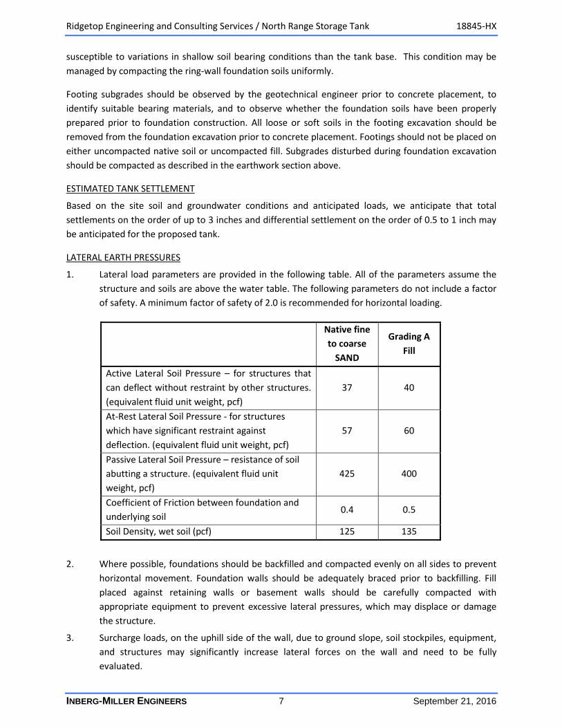
1. Lateral load parameters are provided in the following table. All of the parameters assume the
structure and soils are above the water table. The following parameters do not include a factor
of safety. A minimum factor of safety of 2.0 is recommended for horizontal loading.
Native fine
to coarse
SAND
Grading A
Fill
Active Lateral Soil Pressure – for structures that
can deflect without restraint by other structures.
(equivalent fluid unit weight, pcf)
37 40
At-Rest Lateral Soil Pressure - for structures
which have significant restraint against
deflection. (equivalent fluid unit weight, pcf)
57 60
Passive Lateral Soil Pressure – resistance of soil
abutting a structure. (equivalent fluid unit
weight, pcf)
425 400
Coefficient of Friction between foundation and
underlying soil 0.4 0.5
Soil Density, wet soil (pcf) 125 135
2. Where possible, foundations should be backfilled and compacted evenly on all sides to prevent
horizontal movement. Foundation walls should be adequately braced prior to backfilling. Fill
placed against retaining walls or basement walls should be carefully compacted with
appropriate equipment to prevent excessive lateral pressures, which may displace or damage
the structure.
3. Surcharge loads, on the uphill side of the wall, due to ground slope, soil stockpiles, equipment,
and structures may significantly increase lateral forces on the wall and need to be fully
evaluated.
Ridgetop Engineering and Consulting Services / North Range Storage Tank 18845-HX
INBERG-MILLER ENGINEERS 8 September 21, 2016
4. Drains should be installed behind retaining walls or other confined areas where surface
precipitation and runoff water can collect. Drains should be designed to prevent the build-up of
hydrostatic pressures behind the retaining structures due to trapped water.
GENERAL
1. The measured water-soluble sulfate content of 0-50 ppm for samples from Test Boring B-2 at a
depth of 5 feet and from Test Boring B-4 at a depth of 2.5 feet indicates that the soils do not
contain sufficient sulfates to be very reactive with cement. According to American Concrete
Institute (ACI) and Portland Cement Association (PCA) guidelines, no special provisions for
cement type or water/cementitious material ratio are required for sulfate resistance of portland
cement concrete.
Concrete mixes should be designed to resist alkali silica reactions (ASR). ASR is a serious problem
in the Cheyenne area due to local aggregates which adversely react with portland cement. The
ASR reaction results in formation of a gel within the concrete, which absorbs moisture and
expands. The expansion of the gel results in severe cracking of concrete exposed to moisture.
ASR is normally mitigated by Cheyenne concrete producers by replacing local coarse aggregate
with non-reactive aggregates and/or blending Class F Fly Ash or a lithium compound with
portland cement. Concrete mixes should meet the requirements of the City of Cheyenne Public
Works Standards (August 2003).
2. Rainwater discharge from the tank roof, parking, and drive areas should be directed toward
collection points and disposed of away from the tank in an adequate and efficient manner.
3. In order to promote drainage away from the tank, we recommend that final exterior grades
slope away from the building at a slope of 5 percent for a minimum distance of 10 feet.
4. In accordance with the International Building Code (IBC), 2003 Edition, Table 1615.1.1, we
recommend site Class D for determination of design spectral response acceleration parameters
per IBC. This class is based on Standard Penetration Resistance blow count numbers (N-values)
per ASTM D1586 and the assumption that the subsurface soil conditions encountered in the test
borings can be projected deeper into the earth to describe the average soil conditions for the
top 100 feet. Class D describes the average soil properties of the top 100 feet as stiff silt and clay
(15 < Standard Penetration Test blow count N < 50 and 1,000 psf < undrained shear strength <
2,000 psf).
5. Inberg-Miller Engineers should review final plans and specifications in order to determine
whether the intent of our recommendations has been properly implemented. In addition, we
should be retained as the geotechnical engineer and construction materials testing agency to
provide the following services:
a) Observe excavations to determine if subsurface conditions revealed are consistent with
those discovered in the exploration.
b) Identify if the proper bearing stratum is exposed at proposed foundation excavation
depths.
Ridgetop Engineering and Consulting Services / North Range Storage Tank 18845-HX
INBERG-MILLER ENGINEERS 9 September 21, 2016
c) Observe that foundation excavations are properly prepared, cleaned, and dewatered
prior to concrete placement.
d) Test compaction of subgrades and fills.
e) Perform field and laboratory testing of concrete and other materials as required by
project specification and/or building code.
CONSTRUCTION CONSIDERATIONS
No major difficulties are anticipated for conventional equipment during earthwork construction at the
proposed site. We do not anticipate that groundwater will be encountered at the proposed foundation
depths during construction. However, excavations should be protected from surface water run-off,
whenever possible. Water accumulation within excavations should be promptly removed. If excavation
bottoms become wet, excavation of soils beyond the minimum required depth may be necessary to
provide a firm base for fill placement.
Excavations should be sloped, benched, shored, or made safe for entry by use of trench boxes as
required by the standards of 29 CFR Part 1926. As a safety measure, it is recommended that all vehicles
and soil piles be kept a minimum lateral distance equal to the slope height, from the crest of the slope.
The contractor is solely responsible for designing and constructing stable excavations. Furthermore, the
contractor’s “responsible person” should continuously evaluate the soil exposed in the excavations, the
geometry of the excavation slopes, and the protective equipment and procedures employed by his
forces. For the sole purpose of project planning, we recommend that sand and clayey sand soils to
approximate depths of up to 30 feet be considered an OSHA Type C soil. Excavations, including utility
trenches, extending to depths of greater than 20 feet are required to have side slopes, trench boxes, or
shoring designed by a professional engineer.
CLOSURE
This report has been prepared for the exclusive use of our client, Ridgetop Engineering and Consulting
Services, for evaluation of the site, design, and construction planning purposes of the described project.
All information referenced in the Table of Contents, as well as any future written documents that
address comments or questions regarding this report, constitute the “entire report”. Inberg-Miller
Engineers’ conclusions, opinions, and recommendations are based on the entire report. This report may
contain insufficient information for applications other than those herein described. Our scope of
services was specifically designed for and limited to the specific purpose of providing geotechnical
recommendations for the design of the proposed North Range Storage Tank project. Consequently, this
report may contain insufficient information for applications other than those herein described.
We appreciate participating in your project. We can offer services under a separate contract to provide
civil or environment engineering services, review final plans and specifications, perform construction
surveying, field and laboratory construction materials testing, and observe excavations, as may be
required. Please call us at 307-635-6827 if you have any questions regarding this report.

APPENDIX A
Ridgetop Engineering and Consulting Services / North Range Storage Tank 18845-HX
INBERG-MILLER ENGINEERS September 20, 2016
Site Location Map
Source: Google Earth
Proposed North Range Tank
Location
Ridgetop Engineering and Consulting Services / North Range Storage Tank 18845-HX
INBERG-MILLER ENGINEERS September 20, 2016
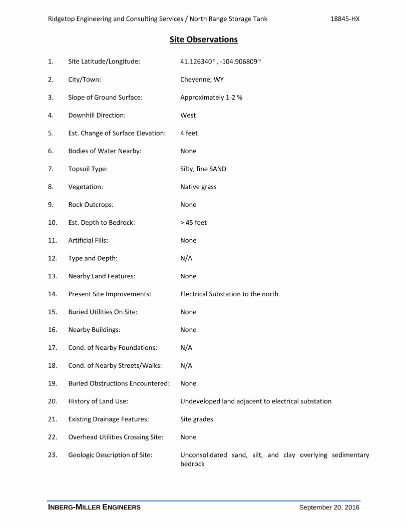
Site Observations
1. Site Latitude/Longitude: 41.126340°, -104.906809° 2. City/Town: Cheyenne, WY 3. Slope of Ground Surface: Approximately 1-2 % 4. Downhill Direction: West 5. Est. Change of Surface Elevation: 4 feet 6. Bodies of Water Nearby: None 7. Topsoil Type: Silty, fine SAND 8. Vegetation: Native grass 9. Rock Outcrops: None 10. Est. Depth to Bedrock: > 45 feet 11. Artificial Fills: None 12. Type and Depth: N/A 13. Nearby Land Features: None 14. Present Site Improvements: Electrical Substation to the north 15. Buried Utilities On Site: None 16. Nearby Buildings: None 17. Cond. of Nearby Foundations: N/A 18. Cond. of Nearby Streets/Walks: N/A 19. Buried Obstructions Encountered: None 20. History of Land Use: Undeveloped land adjacent to electrical substation 21. Existing Drainage Features: Site grades 22. Overhead Utilities Crossing Site: None 23. Geologic Description of Site: Unconsolidated sand, silt, and clay overlying sedimentary
bedrock
Ridgetop Engineering and Consulting Services / North Range Storage Tank 18845-HX
INBERG-MILLER ENGINEERS September 20, 2016
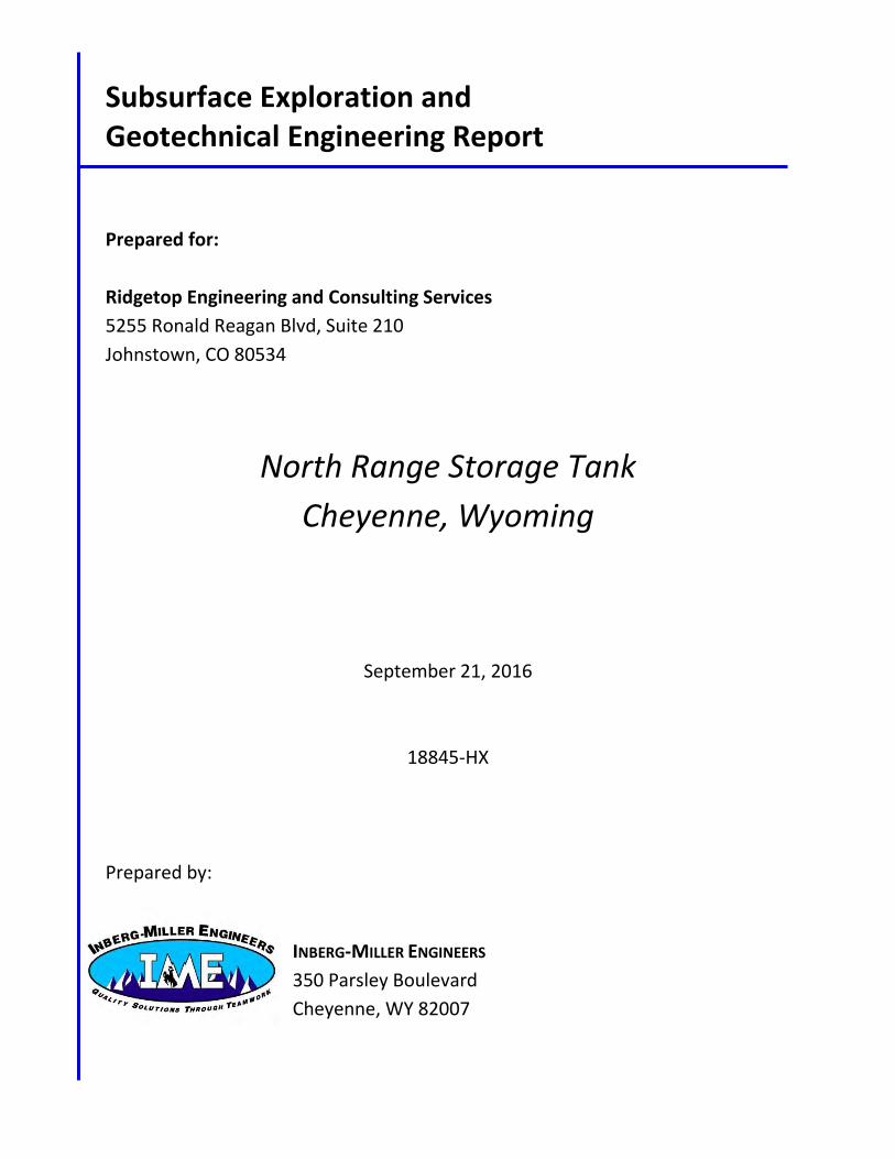
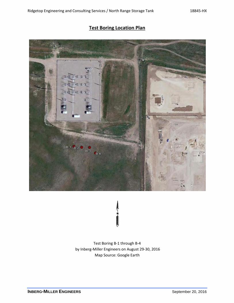
Test Boring Location Plan
Test Boring B-1 through B-4
by Inberg-Miller Engineers on August 29-30, 2016
Map Source: Google Earth

APPENDIX B
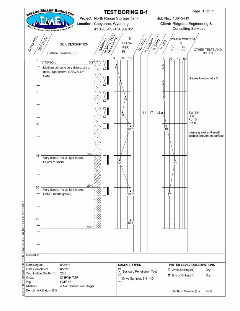
47 SW-SMLL= 0PL= 0PI= 0
Grades to moist at 2.5'
coarse gravel and smallcobbles brought to surface
TOPSOIL
Medium dense to very dense, dry tomoist, light brown, GRAVELLYSAND
Very dense, moist, light brown,CLAYEY SAND
Very dense, moist, light brown,SAND, (some gravel)
0.2
15.0
20.0
26.5
1241
Crew:Rig:
Benchmark/Datum (Ft):
Date Completed:Termination Depth (ft):
Method:
Date Begun: 8/29/168/29/16
CME-85
26.5
Remarks:
IO BWH TGF
SAMPLE TYPES
Standard Penetration Test
Drive Sampler, 2.41-I.D.
While Drilling (ft)
End of Drilling(ft)
WATER LEVEL OBSERVATIONS
Dry
Dry
22.0Depth to Cave In (Ft):
4 1/4" Hollow Stem Auger
LL
WATER CONTENT
20 400 60
% G
RA
VE
L
Client:
% S
AN
D
SA
MP
LE T
YP
E
RE
CO
VE
RY
OTHER TESTS ANDNOTES
100
Qp
(TS
F)
Job No.:
Location:E
LEV
ATI
ON
0
5
10
15
20
25
DE
PTH
(ft)
Ft
0
GR
AP
HIC
18845-HXNorth Range Storage TankProject:
PL
Ridgetop Engineering &Consulting Services
Cheyenne, Wyoming
% -
200
Page 1 of 1
PER
BLOWSN
TEST BORING B-1
Surface Elevation (Ft):
SOIL DESCRIPTION
41.12634°, -104.90705°
50
LOG
OF
TE
ST
BO
RIN
G O
R T
ES
T P
IT 1
8845
-HX
.GP
J IN
B_M
LLR
6-2
3-10
.GD
T 9
/20
/16
3
3
4
5
10
31
17
15
39
69
50
50/3"
32
50/3"
50/4"
62 SCLL= 32PL= 15PI= 17
W.S.S. < 50 ppm
TOPSOIL
Medium dense to dense, dry, lightbrown, GRAVELLY SAND
Medium dense, moist, light brown,SAND
Very dense, moist, light brown,CLAYEY SAND, (with gravel)
Dense to very dense, moist, lightbrown, SILTY SAND
Dense, moist, light brown, siltySAND (weathered sandstonebedrock)
0.2
7.5
16.0
20.0
40.0
76.5
380
Crew:Rig:
Benchmark/Datum (Ft):
Date Completed:Termination Depth (ft):
Method:
Date Begun: 8/30/168/30/16
CME-85
76.5
Remarks:
IO BWH TGF
SAMPLE TYPES
Standard Penetration Test
Drive Sampler, 2.41-I.D.
While Drilling (ft)
End of Drilling(ft)
WATER LEVEL OBSERVATIONS
55.0
44.0
67.0Depth to Cave In (Ft):
4 1/4" Hollow Stem Auger
LL
WATER CONTENT
20 400 60
% G
RA
VE
L
Client:
% S
AN
D
SA
MP
LE T
YP
E
RE
CO
VE
RY
OTHER TESTS ANDNOTES
100
Qp
(TS
F)
Job No.:
Location:E
LEV
ATI
ON
0
5
10
15
20
25
30
35
40
45
50
55
60
65
70
75
DE
PTH
(ft)
Ft
0
GR
AP
HIC
18845-HXNorth Range Storage TankProject:
PL
Ridgetop Engineering &Consulting Services
Cheyenne, Wyoming
% -
200
Page 1 of 1
PER
BLOWSN
TEST BORING B-2
Surface Elevation (Ft):
SOIL DESCRIPTION
41.12635°, -104.90683°
50
LOG
OF
TE
ST
BO
RIN
G O
R T
ES
T P
IT 1
8845
-HX
.GP
J IN
B_M
LLR
6-2
3-10
.GD
T 9
/20
/16
2
3
3
11
12
17
16
29
23
19
10
21
23
26
18
23
20
19
22
36
49
21
27
64
59
35
50/5"
44
41
48
38
28
61
71 SW-SMLL= 0PL= 0PI= 0
grades to moist
TOPSOIL
Medium dense to dense, dry, lightbrown, GRAVELLY SAND
Medium dense, moist, light brown,CLAYEY SAND, (with gravel)
Very dense, moist, light brown,CLAYEY SAND
0.2
15.0
25.0
26.5920
Crew:Rig:
Benchmark/Datum (Ft):
Date Completed:Termination Depth (ft):
Method:
Date Begun: 8/29/168/29/16
CME-85
26.5
Remarks:
IO BWH TGF
SAMPLE TYPES
Standard Penetration Test
Drive Sampler, 2.41-I.D.
While Drilling (ft)
End of Drilling(ft)
WATER LEVEL OBSERVATIONS
Dry
Dry
21.5Depth to Cave In (Ft):
4 1/4" Hollow Stem Auger
LL
WATER CONTENT
20 400 60
% G
RA
VE
L
Client:
% S
AN
D
SA
MP
LE T
YP
E
RE
CO
VE
RY
OTHER TESTS ANDNOTES
100
Qp
(TS
F)
Job No.:
Location:E
LEV
ATI
ON
0
5
10
15
20
25
DE
PTH
(ft)
Ft
0
GR
AP
HIC
18845-HXNorth Range Storage TankProject:
PL
Ridgetop Engineering &Consulting Services
Cheyenne, Wyoming
% -
200
Page 1 of 1
PER
BLOWSN
TEST BORING B-3
Surface Elevation (Ft):
SOIL DESCRIPTION
41.12635°, -104.90663°
50
LOG
OF
TE
ST
BO
RIN
G O
R T
ES
T P
IT 1
8845
-HX
.GP
J IN
B_M
LLR
6-2
3-10
.GD
T 9
/20
/16
4
5
4
2
4
42
19
22
30
26
30
43
35
28
50/5"
W.S.S. < 50 ppm
large gravel to cobblesencountered
TOPSOIL
Medium dense, dry, light brown,GRAVELLY SAND
Very loose to dense, moist, lightbrown to pale yellow, SAND
Dense, moist, light brown, CLAYEYSAND, (with gravel)
Medium dense, moist, light brown tobrown, SILTY SAND
0.1
5.0
15.0
20.0
26.5
Crew:Rig:
Benchmark/Datum (Ft):
Date Completed:Termination Depth (ft):
Method:
Date Begun: 8/30/168/30/16
CME-85
26.5
Remarks:
IO BWH TGF
SAMPLE TYPES
Standard Penetration Test While Drilling (ft)
End of Drilling(ft)
WATER LEVEL OBSERVATIONS
Dry
Dry
21.4Depth to Cave In (Ft):
4 1/4" Hollow Stem Auger
LL
WATER CONTENT
20 400 60
% G
RA
VE
L
Client:
% S
AN
D
SA
MP
LE T
YP
E
RE
CO
VE
RY
OTHER TESTS ANDNOTES
100
Qp
(TS
F)
Job No.:
Location:E
LEV
ATI
ON
0
5
10
15
20
25
DE
PTH
(ft)
Ft
0
GR
AP
HIC
18845-HXNorth Range Storage TankProject:
PL
Ridgetop Engineering &Consulting Services
Cheyenne, Wyoming
% -
200
Page 1 of 1
PER
BLOWSN
TEST BORING B-4
Surface Elevation (Ft):
SOIL DESCRIPTION
41.1263°, -104.90648°
50
LOG
OF
TE
ST
BO
RIN
G O
R T
ES
T P
IT 1
8845
-HX
.GP
J IN
B_M
LLR
6-2
3-10
.GD
T 9
/20
/16
5
7
9
7
5
24
19
40
17
21
3
25
26
39
30
13
INBERG-MILLER ENGINEERS 1
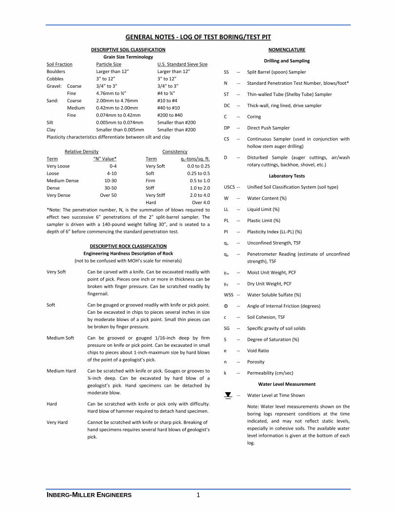
GENERAL NOTES - LOG OF TEST BORING/TEST PIT
DESCRIPTIVE SOIL CLASSIFICATION
Grain Size Terminology
Soil Fraction Particle Size U.S. Standard Sieve Size
Boulders Larger than 12” Larger than 12”
Cobbles 3” to 12” 3” to 12”
Gravel: Coarse 3/4” to 3” 3/4” to 3”
Fine 4.76mm to ¾” #4 to ¾”
Sand: Coarse 2.00mm to 4.76mm #10 to #4
Medium 0.42mm to 2.00mm #40 to #10
Fine 0.074mm to 0.42mm #200 to #40
Silt 0.005mm to 0.074mm Smaller than #200
Clay Smaller than 0.005mm Smaller than #200
Plasticity characteristics differentiate between silt and clay
Relative Density Consistency
Term “N” Value* Term qu-tons/sq. ft.
Very Loose 0-4 Very Soft 0.0 to 0.25
Loose 4-10 Soft 0.25 to 0.5
Medium Dense 10-30 Firm 0.5 to 1.0
Dense 30-50 Stiff 1.0 to 2.0
Very Dense Over 50 Very Stiff 2.0 to 4.0
Hard Over 4.0
*Note: The penetration number, N, is the summation of blows required to
effect two successive 6” penetrations of the 2” split-barrel sampler. The
sampler is driven with a 140-pound weight falling 30”, and is seated to a
depth of 6” before commencing the standard penetration test.
DESCRIPTIVE ROCK CLASSIFICATION
Engineering Hardness Description of Rock
(not to be confused with MOH’s scale for minerals)
Very Soft Can be carved with a knife. Can be excavated readily with
point of pick. Pieces one inch or more in thickness can be
broken with finger pressure. Can be scratched readily by
fingernail.
Soft Can be gouged or grooved readily with knife or pick point.
Can be excavated in chips to pieces several inches in size
by moderate blows of a pick point. Small thin pieces can
be broken by finger pressure.
Medium Soft Can be grooved or gouged 1/16-inch deep by firm
pressure on knife or pick point. Can be excavated in small
chips to pieces about 1-inch-maximum size by hard blows
of the point of a geologist’s pick.
Medium Hard Can be scratched with knife or pick. Gouges or grooves to
¼-inch deep. Can be excavated by hard blow of a
geologist’s pick. Hand specimens can be detached by
moderate blow.
Hard Can be scratched with knife or pick only with difficulty.
Hard blow of hammer required to detach hand specimen.
Very Hard Cannot be scratched with knife or sharp pick. Breaking of
hand specimens requires several hard blows of geologist’s
pick.
NOMENCLATURE
Drilling and Sampling
SS -- Split Barrel (spoon) Sampler
N -- Standard Penetration Test Number, blows/foot*
ST -- Thin-walled Tube (Shelby Tube) Sampler
DC -- Thick-wall, ring lined, drive sampler
C -- Coring
DP -- Direct Push Sampler
CS -- Continuous Sampler (used in conjunction with
hollow stem auger drilling)
D -- Disturbed Sample (auger cuttings, air/wash
rotary cuttings, backhoe, shovel, etc.)
Laboratory Tests
USCS -- Unified Soil Classification System (soil type)
W -- Water Content (%)
LL -- Liquid Limit (%)
PL -- Plastic Limit (%)
PI -- Plasticity Index (LL-PL) (%)
qu -- Unconfined Strength, TSF
qp -- Penetrometer Reading (estimate of unconfined
strength), TSF
γm -- Moist Unit Weight, PCF
γd -- Dry Unit Weight, PCF
WSS -- Water Soluble Sulfate (%)
Φ -- Angle of Internal Friction (degrees)
c -- Soil Cohesion, TSF
SG -- Specific gravity of soil solids
S -- Degree of Saturation (%)
e -- Void Ratio
n -- Porosity
k -- Permeability (cm/sec)
Water Level Measurement
-- Water Level at Time Shown
Note: Water level measurements shown on the
boring logs represent conditions at the time
indicated, and may not reflect static levels,
especially in cohesive soils. The available water
level information is given at the bottom of each
log.
INBERG-MILLER ENGINEERS 1
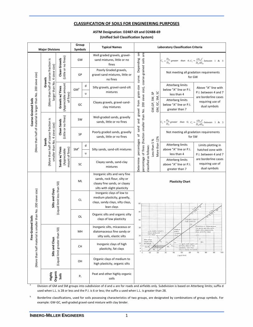
CLASSIFICATION OF SOILS FOR ENGINEERING PURPOSES
ASTM Designation: D2487-69 and D2488-69
(Unified Soil Classification System)
Major Divisions
Group
Symbols Typical Names Laboratory Classification Criteria
Co
arse
-Gra
ine
d S
oils
(M
ore
th
an h
alf
of
mat
eria
l is
larg
er t
han
No
. 20
0 s
ieve
siz
e)
Gra
vels
(M
ore
th
an h
alf
of
coar
se f
ract
ion
is
larg
er t
han
No
. 4 s
ieve
siz
e)
Cle
an G
rave
ls
(Lit
tle
or
no
fin
es)
GW
Well graded gravels, gravel-
sand mixtures, little or no
fines
Det
erm
ine
per
cen
tage
s o
f sa
nd
an
d
grav
el
fro
m
grai
n-s
ize
curv
e.
Dep
end
ing
on
per
cen
tage
of
fin
es (
frac
tio
n s
mal
ler
than
No
. 2
00
sie
ve s
ize)
, co
arse
-gra
ined
so
ils a
re
clas
sifi
ed a
s fo
llow
s:
Le
ss t
han
5 %
GW
,GP
, SW
, SP
M
ore
th
an 1
2%
GM
, GC
, SM
, SC
5
to
12
%
Bo
rder
line
case
s re
qu
irin
g d
ual
sym
bo
lsb
GP
Poorly Graded gravels,
gravel-sand mixtures, little or
no fines
Not meeting all gradation requirements
for GW
Gra
vels
w/
Fin
es
(Ap
pre
ciab
le a
mo
un
t
of
fin
es)
GMa d Silty gravels, gravel-sand-silt
mixtures
Atterberg limits
below “A” line or P.I.
less than 4
Above “A” line with
P.I. between 4 and 7
are borderline cases
requiring use of
dual symbols
u
GC Clayey gravels, gravel-sand-
clay mixtures
Atterberg limits
below “A” line or P.I.
greater than 7
San
ds
(Mo
re t
han
hal
f o
f co
arse
fra
ctio
n is
smal
ler
than
No
. 4 s
ieve
siz
e)
Cle
an S
and
s (L
ittl
e o
r n
o f
ines
)
SW Well-graded sands, gravelly
sands, little or no fines
SP Poorly graded sands, gravelly
sands, little or no fines
Not meeting all gradation requirements
for SW
San
ds
w/
Fin
es
(Ap
pre
ciab
le
mo
un
t o
f fi
nes
)
SMa d
Silty sands, sand-silt mixtures
Atterberg limits
above “A” line or P.I.
less than 4
Limits plotting in
hatched zone with
P.I. between 4 and 7
are borderline cases
requiring use of
dual symbols
u
SC Clayey sands, sand-clay
mixtures
Atterberg limits
above “A” line or P.I.
greater than 7
Fin
e-G
rain
ed S
oils
(Mo
re t
han
hal
f m
ater
ial i
s sm
alle
r th
an N
o. 2
00
sie
ve s
ize
)
Silt
s an
d C
lays
(Liq
uid
lim
it le
ss t
han
50
) ML
Inorganic silts and very fine
sands, rock flour, silty or
clayey fine sands, or clayey
silts with slight plasticity
Plasticity Chart
CL
Inorganic clays of low to
medium plasticity, gravelly,
clays, sandy clays, silty clays,
lean clays
OL Organic silts and organic silty
clays of low plasticity
Silt
s an
d C
lays
(Liq
uid
lim
it g
reat
er t
han
50
)
MH
Inorganic silts, micaceous or
diatomaceous fine sandy or
silty soils, elastic silts
CH Inorganic clays of high
plasticity, fat clays
OH Organic clays of medium to
high plasticity, organic silts
Hig
hly
Org
anic
Soils
Pt Peat and other highly organic
soils
a Division of GM and SM groups into subdivision of d and u are for roads and airfields only. Subdivision is based on Atterberg limits; suffix d
used when L.L. is 28 or less and the P.I. is 6 or less; the suffix u used when L.L. is greater than 28.
b Borderline classifications, used for soils possessing characteristics of two groups, are designated by combinations of group symbols. For
example: GW-GC, well-graded gravel-sand mixture with clay binder.
;410
60 thangreaterD
DCu 3&1
)(
6010
2
30 betweenxDD
DCc
;610
60 thangreaterD
DCu 3&1
)(
6010
2
30 betweenxDD
DCc

APPENDIX C
0
5
10
15
20
25
30
35
40
45
50
55
60
65
70
75
80
85
90
95
100
0.0010.010.1110100
12.0
37.7
8.9
D60
10 14
Specimen Identification
Specimen Identification D10
U.S. SIEVE NUMBERS
7.5
30.0
25.0
162
CuPI
GRAIN SIZE IN MILLIMETERS
PE
RC
EN
T F
INE
R B
Y W
EIG
HT
41 3/4 3/8 3
%Gravel %Sand %Silt %Clay
B-1
B-2
B-3
100 1403 1/2 60
fine
HYDROMETERU.S. SIEVE OPENING IN INCHES
fine coarse medium
B-1
B-2
B-3
LL PL
4.994
0.111
1.77
25
4.75
25
0.605
0.501 0.085
200
D100
GRAVEL
85.71
20.87
1.26
1.67
1.5
Classification
coarseCOBBLES
Cc
20 30 40 50
SANDSILT OR CLAY
4
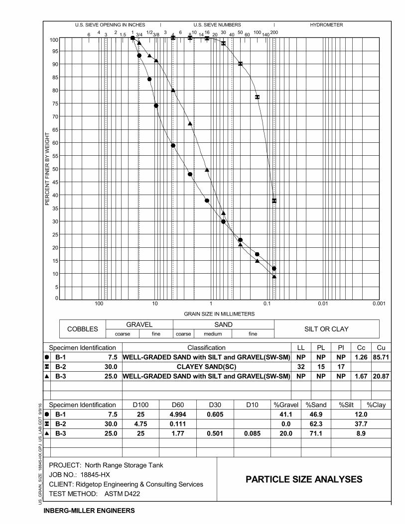
WELL-GRADED SAND with SILT and GRAVEL(SW-SM)
CLAYEY SAND(SC)
WELL-GRADED SAND with SILT and GRAVEL(SW-SM)
NP
17
NP
66 8
D30
NP
15
NP
NP
32
NP
PARTICLE SIZE ANALYSES
41.1
0.0
20.0
7.5
30.0
25.0
46.9
62.3
71.1
INBERG-MILLER ENGINEERS
PROJECT: North Range Storage Tank
JOB NO.: 18845-HX
CLIENT: Ridgetop Engineering & Consulting Services
TEST METHOD: ASTM D422
US
_GR
AIN
_SIZ
E 1
8845
-HX
.GP
J U
S_L
AB
.GD
T 9
/9/1
6
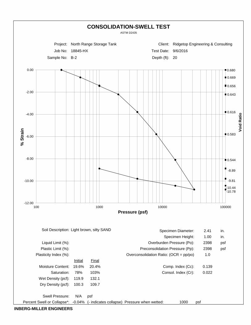
Project: North Range Storage Tank Client: Ridgetop Engineering & Consulting
Job No: 18845-HX Test Date: 9/6/2016
Sample No: B-2 Depth (ft): 20
Soil Description: Specimen Diameter: 2.41 in.
Specimen Height: 1.00 in.
Liquid Limit (%): Overburden Pressure (Po): 2398 psf
Plastic Limit (%): Preconsolidation Pressure (Pp): 2398 psf
Plasticity Index (%): Overconsolidation Ratio: (OCR = pp/po) 1.0
Initial Final
Moisture Content: 19.6% 20.4% Comp. Index (Cc): 0.139
Saturation: 78% 103% Consol. Index (Cr): 0.022
Wet Density (pcf): 119.9 132.1
Dry Density (pcf): 100.3 109.7
Swell Pressure: N/A psf
Percent Swell or Collapse*: -0.04% (- indicates collapse) Pressure when wetted: 1000 psf
INBERG-MILLER ENGINEERS
Light brown, silty SAND
CONSOLIDATION-SWELL TESTASTM D2435
Vo
id R
ati
o
0.680
0.669
0.656
0.643
0.616
0.583
0.544
-10.78-10.44
-9.81
-8.89
-12.00
-10.00
-8.00
-6.00
-4.00
-2.00
0.00
100 1000 10000 100000
% S
tra
in
Pressure (psf)
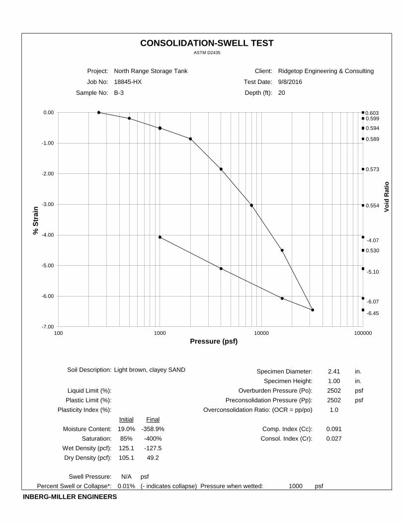
Project: North Range Storage Tank Client: Ridgetop Engineering & Consulting
Job No: 18845-HX Test Date: 9/8/2016
Sample No: B-3 Depth (ft): 20
Soil Description: Specimen Diameter: 2.41 in.
Specimen Height: 1.00 in.
Liquid Limit (%): Overburden Pressure (Po): 2502 psf
Plastic Limit (%): Preconsolidation Pressure (Pp): 2502 psf
Plasticity Index (%): Overconsolidation Ratio: (OCR = pp/po) 1.0
Initial Final
Moisture Content: 19.0% -358.9% Comp. Index (Cc): 0.091
Saturation: 85% -400% Consol. Index (Cr): 0.027
Wet Density (pcf): 125.1 -127.5
Dry Density (pcf): 105.1 49.2
Swell Pressure: N/A psf
Percent Swell or Collapse*: 0.01% (- indicates collapse) Pressure when wetted: 1000 psf
INBERG-MILLER ENGINEERS
Light brown, clayey SAND
CONSOLIDATION-SWELL TESTASTM D2435
Vo
id R
ati
o
0.6030.599
0.594
0.589
0.573
0.554
0.530
-6.45
-6.07
-5.10
-4.07
-7.00
-6.00
-5.00
-4.00
-3.00
-2.00
-1.00
0.00
100 1000 10000 100000
% S
tra
in
Pressure (psf)

APPENDIX D
INBERG-MILLER ENGINEERS 1
LIMITATIONS AND USE OF THIS REPORT
This report has been prepared by Inberg-Miller Engineers, hereinafter referred to as "IME", to evaluate
this property for the intended use described herein. If any changes of the facility are planned with
respect to the design vertical position or horizontal location as outlined herein, we recommend that the
changes be reviewed, and the conclusions and recommendations of this report be modified in writing by
IME.
The analyses and recommendations submitted in this report are our opinions based on the data
obtained, and subsurface conditions noted from the field exploration. The locations of the exploration
are illustrated on the accompanying map and diagram. Any variations that may occur between, beyond,
or below the depths of test borings or test pits, are not presented in this report because these areas
were not specifically explored. Excavations during the construction phases may reveal variations from
subsurface conditions identified in our exploration. The nature and extent of such variations may not
become evident until excavation and construction begins. If variations appear evident during
construction, we advise a re-evaluation of the recommendations in this report. After performing
additional on-site observations, we can provide an addendum to our recommendations noting the
characteristics of any variations.
IME is responsible for the conclusions and opinions contained in this report based on the supplied data
relative only to the specific project and location outlined in this report. If conclusions or
recommendations are made by others, IME should be given an opportunity to review and comment on
such conclusions or recommendations in writing, prior to the completion of the project design phase.
It is recommended that IME be provided the opportunity to review final designs, plans, and
specifications using the conclusions of this report, in order to determine whether any change in concept
may have any effect on the validity of the recommendations contained in this document. If IME is
accorded the privilege of this review, IME can assist in avoiding misinterpretation or misapplication of
these recommendations if changes have been made as compared with IME’s understanding of either
the project or design content. Review of the final design, plans, and specifications will be noted in
writing by IME upon client's request, and will become a part of this report.
Standards are referenced by designated letters/numbers in several locations within this report. These
standards were identified for the sole purpose of informing the reader what test methods were
followed by IME during the execution of IME’s scope of services. Anyone who reads, references, or relies
on this report for any purpose whatsoever is hereby advised that IME has applied professional judgment
in determining the extent to which IME complied with any given standard identified in this report or any
other instrument of IME’s professional service. Unless otherwise indicated, such compliance referred to
as “general compliance,” specifically excluded consideration of any standard listed as a reference in the
text of those standards IME has cited. Questions about general compliance – i.e., which elements of a
cited standard were followed and to what extent, should be directed to IME.
IME has performed exploration, laboratory, and engineering services sufficient to provide geotechnical
information that is adequate for either the preliminary planning or the design phase of the project, as
INBERG-MILLER ENGINEERS 2
stated herein. IME’s scope of services was developed and agreed to specifically for this purpose.
Consequently, this report may be insufficient for other purposes. For example, this report may be
insufficient for the contractor or his subcontractors to prepare an accurate bid for the construction
phase of the project. The client, owner, potential contractors, and subcontractors are advised that it is
specifically the contractor’s and subcontractor’s obligation and responsibility during the bidding process
to collect whatever additional information they deem necessary to prepare an accurate bid. The
contractor’s and subcontractor’s bid should include selection of personnel, equipment, bits, etc. that are
necessary to complete the project according to the project specifications, on schedule, within budget,
and without change orders resulting from unforeseen geologic conditions.
Variations in soil conditions may be encountered during construction. To permit correlation between
soil data in this report and the actual soil conditions encountered during construction, we recommend
that IME be retained to perform construction observations of the earthwork and foundation phases of
the work. It is recommended that IME be retained to observe all areas where fills are to be placed, and
test and approve each class of fill material to be used according to the recommendations for compacted
fill presented in this report. IME can provide specific assistance in evaluating construction compliance
with the design concepts, specifications, or recommendations if IME has been retained to perform
continuous on-site observations and materials testing during construction.
The presence of IME’s field representative, if such services are requested by the client, will be for the
sole purpose of providing record observations and field materials testing. We recommend the
contractor be solely responsible for supervision, management, or direction of the actual work of the
contractor, his employees, or agents. The contractor for this project should be so advised. The
contractor should also be informed that neither the presence of our field representative or the
observation and testing by our firm shall excuse him in any way for defects discovered in his work. It is
understood that IME will not be responsible for job or site safety on this project.
This report has been prepared in accordance with generally accepted geotechnical engineering
practices, and makes no warranties, either expressed or implied. The services performed by IME in
preparing this report have been conducted in a manner consistent with that level of care and skill
ordinarily exercised by members of the profession currently practicing in the same locality under similar
conditions. No other representation, express or implied, and no warranty or guarantee is included or
intended in this report. The report has not been prepared for other uses or parties other than those
specifically named, or for uses or applications other than those enumerated herein. The report may
contain insufficient or inaccurate information for other purposes, applications, building sites, or other
uses.
INBERG-MILLER ENGINEERS 1
SAMPLE AND DATA COLLECTION INFORMATION
Field-sampling techniques were employed in this exploration to obtain the data presented in the Final
Logs and Report generally in accordance with ASTM D420, D1452, D1586 (where applicable), and D1587
(where applicable).
The drilling method utilized in most test borings is a dry-process, machine rotary auger type that
advances hollow steel pipe surrounded by attached steel auger flights in 5-foot lengths. This method
creates a continuously cased test hole that prevents the boring from caving in above each level of
substrata to be tested. Sampling tools were lowered inside the hollow shaft for testing in the
undisturbed soils below the lead auger. In some test borings, as appropriate to advance to the desired
depth, air or wash rotary drilling methods were utilized. Air or wash rotary drilling methods allow for the
extraction of rock core samples.
Samples were brought to the surface, examined by an IME field representative, and sealed in containers
(or sealed in the tubes) to prevent a significant loss of moisture. They were returned to our laboratory
for final classification per ASTM D2487 methods. Some samples were subjected to field or laboratory
tests as described in the text of this report.
Groundwater observations were made with cloth-tape measurements in the open drill holes by IME
field personnel at the times and dates stated on the Final Logs. Recorded groundwater levels may not
reflect equilibrium groundwater conditions due to relatively low permeability of some soils. It must also
be noted that fluctuations may occur in the groundwater level due to variations in precipitation,
temperature, nearby site improvements, nearby drainage features, underdrainage, wells, severity of
winter frosts, overburden weights, and the permeability of the subsoil. Because variations may be
expected, final designs and construction planning should allow for the need to temporarily or
permanently dewater excavations or subsoil.
A Final Log of each test pit or boring was prepared by IME. Each Final Log contains IME's interpretation
of field conditions or changes in substrata between recovered samples based on the field data received,
along with the laboratory test data obtained following the field work or on subsequent site
observations. The final logs were prepared by assembling and analyzing field and laboratory data.
Therefore, the Final Logs contain both factual and interpretive information. IME’s opinions are based on
the Final Logs.
The Final Logs list boring methods, sampling methods, approximate depths sampled, amounts of
recovery in sampling tools (where applicable), indications of the presence of subsoil types, and
groundwater observations and measurements. Results of some laboratory tests are arrayed on the Final
Logs at the appropriate depths below grade. The horizontal lines on the Final Logs designate the
interface between successive layers (strata) and represent approximate boundaries. The transition
between strata may be gradual.
We caution that the Final Logs alone do not constitute the report, and as such they should not be
excerpted from the other appendix exhibits or from any of the written text. Without the written report,
it is possible to misinterpret the meaning of the information reported on the Final Logs. If the report is
INBERG-MILLER ENGINEERS 2
reproduced for reference purposes, the entire numbered report and appendix exhibits should be bound
together as a separate document, or as a section of a specification booklet, including all drawings, maps,
etc.
Pocket penetration tests taken in the field, or on samples examined in the laboratory are listed on the
Final Logs in a column marked “qp". These tests were performed only to approximate unconfined
strength and consistency when making comparisons between successive layers of cohesive soil. It is not
recommended that the listed values be used to determine allowable bearing capacities. Bearing
capacities of soil is determined by IME using test methods as described in the text of the report.

i
124 East Main Street
Riverton, WY 82501
307-856-8136
307-856-3851 (fax)
1120 East “C” Street
Casper, WY 82601
307-577-0806
307-856-3851 (fax)
350 Parsley Boulevard
Cheyenne, WY 82007
307-635-6827
307-856-3851 (fax)
816 West Spruce St.
Rawlins, WY 82301
307-856-8136
307-856-3851 (fax)
830 E. Richards, Suite 1
Douglas, WY 82633
307-359-7000
307-856-3851 (fax)
193 W. Flaming Gorge Way
Green River, WY 82935
307-875-4394
307-856-3851 (fax)
www.inberg-miller.com