Embed Size (px)
Citation preview
North Carolina Energy CodeFuture of Commercial Requirements
2008 N th C li E St C f
Future of Commercial Requirements
2008 North Carolina Energy Star ConferenceConducted by:
Chris Mathis and AssociatesAppalachian State University Chris Mathis and AssociatesAsheville, NC
Margie Meares, [email protected]
Appalachian State UniversityDept. of Technology &
Energy CenterBoone, NC
Jeff Tiller PE Jeff Tiller, PE, [email protected]
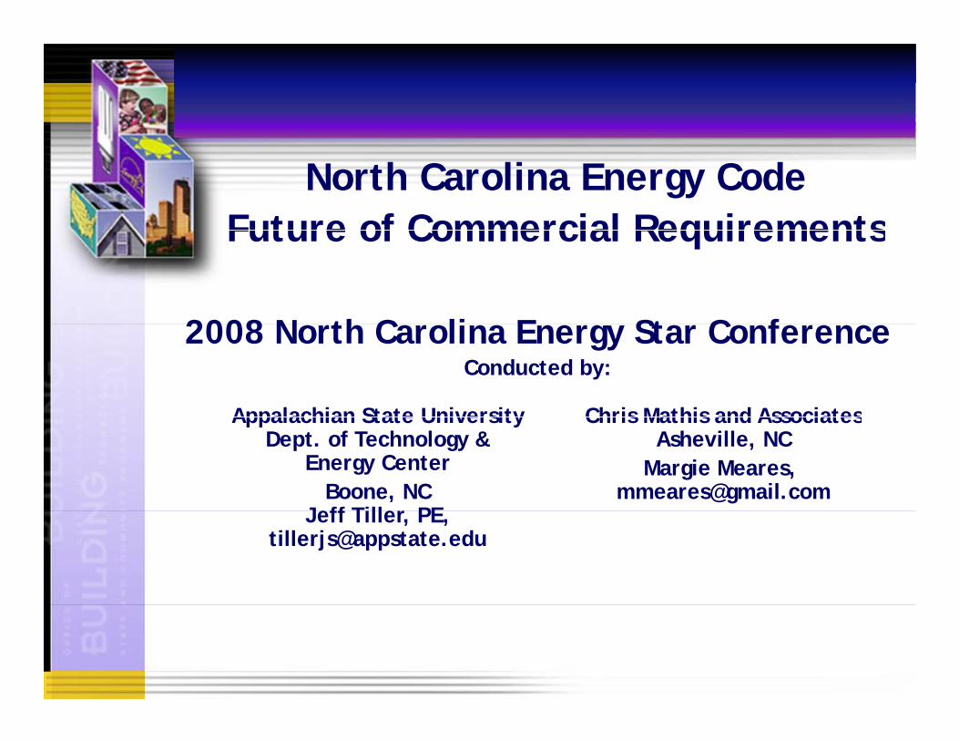
Total Energy Use by Sector (TBtu)Com-
2500
3000 TransportationIndustrialR id ti l
mercial20%Transpor-
portation27%
2000
2500 ResidentialCommercial
Resi-
2004
1000
1500dential26%Indus-
trial27% Com-
500
1000 Commercial
7%Transpor- tation28%
0
960
970
980
990
000
Resi-dentialIndus-
1960
196
197
198
199
200 29%trial
36%
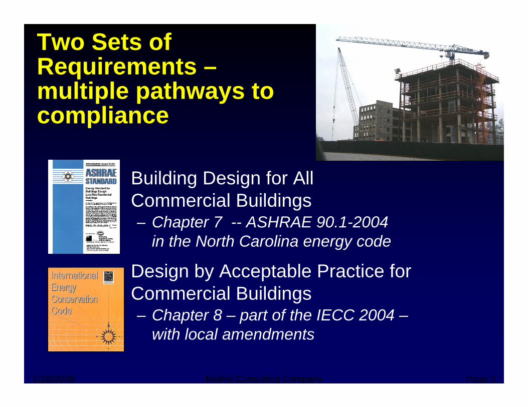
Two Sets of Requirements –qmultiple pathways to compliancep
• Building Design for All• Building Design for All Commercial Buildings– Chapter 7 -- ASHRAE 90.1-2004 p
in the North Carolina energy code
• Design by Acceptable Practice for g y pCommercial Buildings– Chapter 8 – part of the IECC 2004 –
with local amendments
1/28/2008 Mathis Consulting Company Page 3
with local amendments
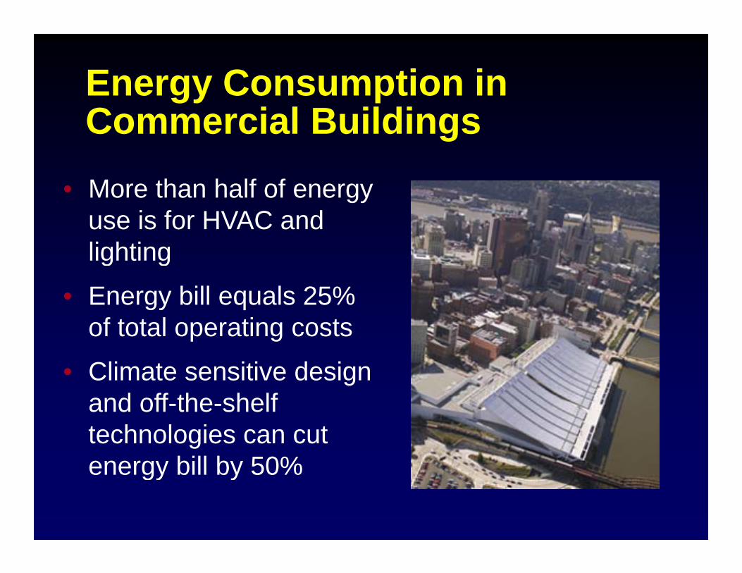
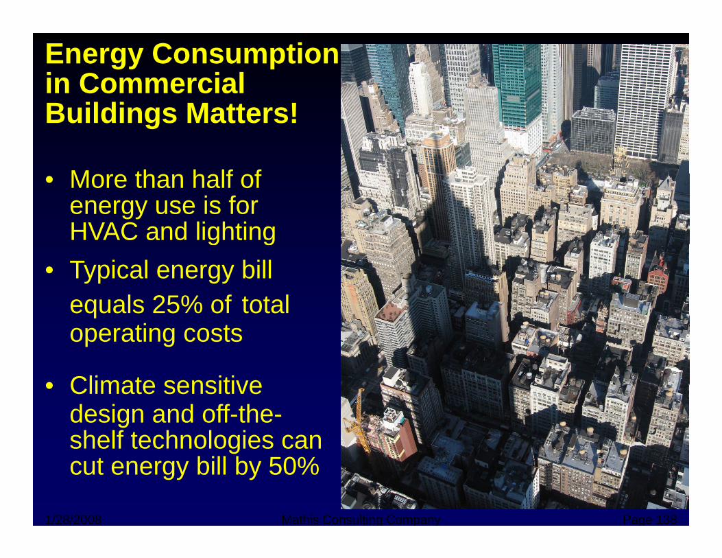
Energy Consumption in Commercial Buildings
• More than half of energy use is for HVAC and lightinglighting
• Energy bill equals 25% of total operating costsof total operating costs
• Climate sensitive design d ff th h lfand off-the-shelf
technologies can cut energy bill by 50%energy bill by 50%
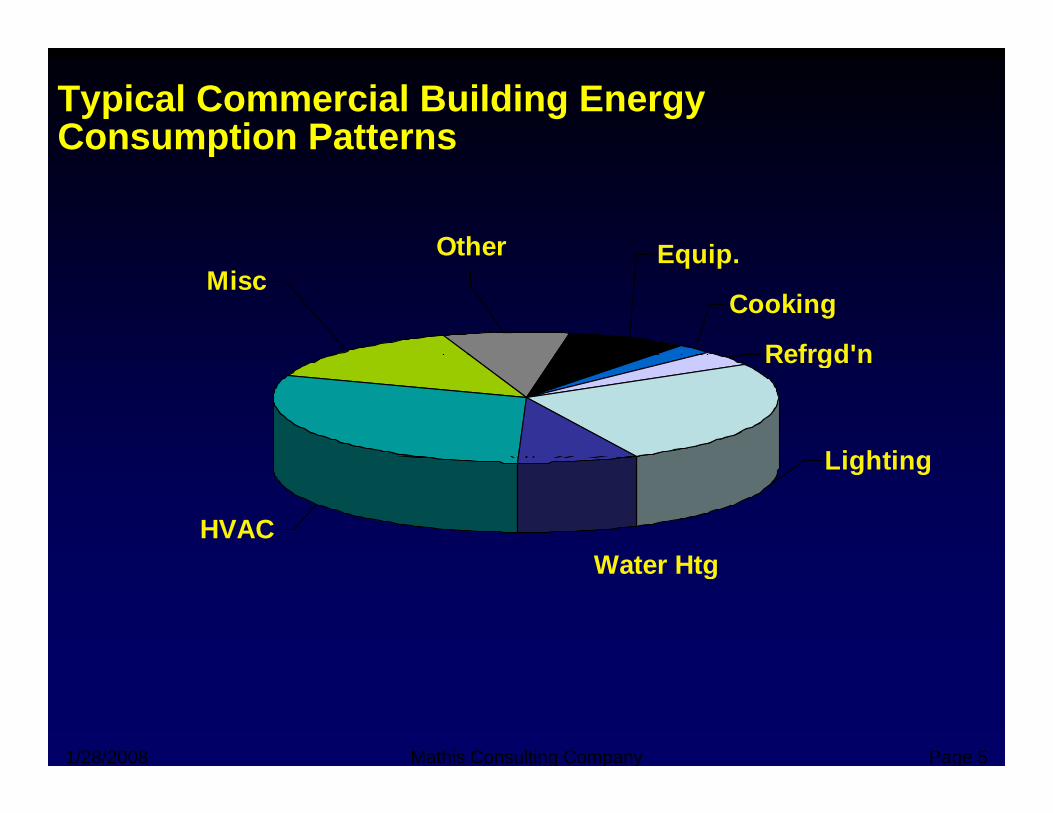
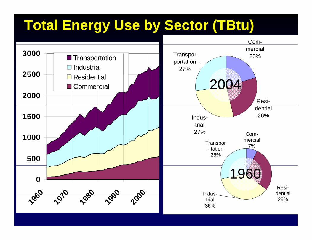
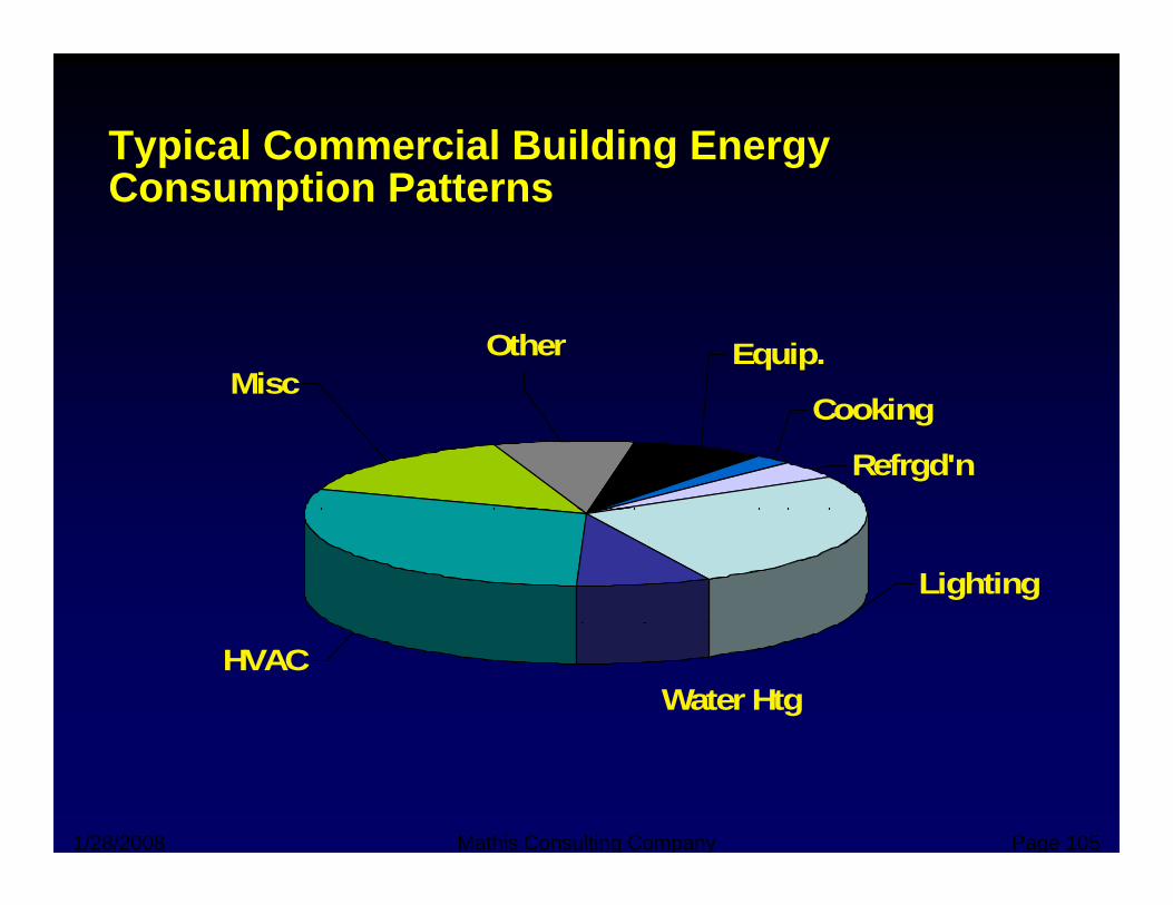
Typical Commercial Building Energy Consumption Patternsp
EquipOther Equip.
Cooking
Refrgd'n
OtherMisc
Refrgd n
LightingLighting
HVACWater HtgWater Htg
1/28/2008 Mathis Consulting Company Page 5
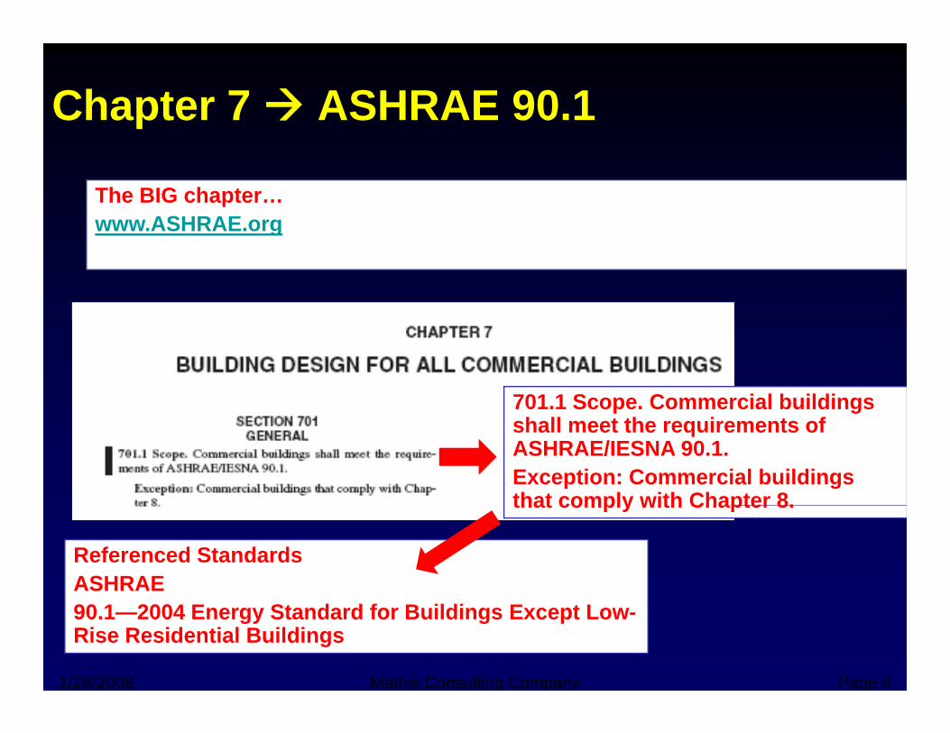
Chapter 7 ASHRAE 90.1
The BIG chapter…www ASHRAE orgwww.ASHRAE.org
701.1 Scope. Commercial buildings p gshall meet the requirements of ASHRAE/IESNA 90.1.Exception: Commercial buildings that comply with Chapter 8.that comply with Chapter 8.
Referenced StandardsASHRAE
1/28/2008 Mathis Consulting Company Page 6
90.1—2004 Energy Standard for Buildings Except Low-Rise Residential Buildings
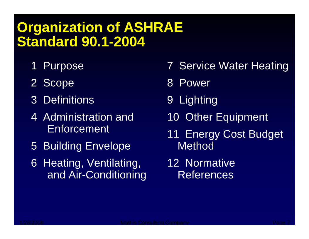
Organization of ASHRAE Standard 90 1-2004Standard 90.1 2004
1 Purpose 7 Service Water Heating2 Scope3 Definitions
8 Power9 Lighting
4 Administration and Enforcement
g g10 Other Equipment11 Energy Cost Budget
5 Building Envelope6 Heating Ventilating
11 Energy Cost Budget Method
12 Normative6 Heating, Ventilating, and Air-Conditioning
12 Normative References
1/28/2008 Mathis Consulting Company Page 7
High Rise Residential – Which Energy Code?Energy Code?
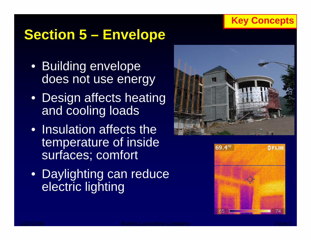
Section 5 – Envelope Key Concepts
• Building envelope d tdoes not use energy
• Design affects heatingand cooling loads
• Insulation affects the temperature of inside surfaces; comfort
• Daylighting can reduce electric lighting
1/28/2008 Mathis Consulting Company Page 9

Section 5 – Envelope, cont’d
• Integrated design approach saves energyg g pp gy
• Building envelope requirements address:– Opaque elements– Opaque elements
• Roofs, walls, floors, below-grade walls, slabs, opaque doors
– Fenestration• Windows, doors, skylights
• How often do we get the chance to get this part of the building right?
1/28/2008 Mathis Consulting Company Page 10
part of the building right?
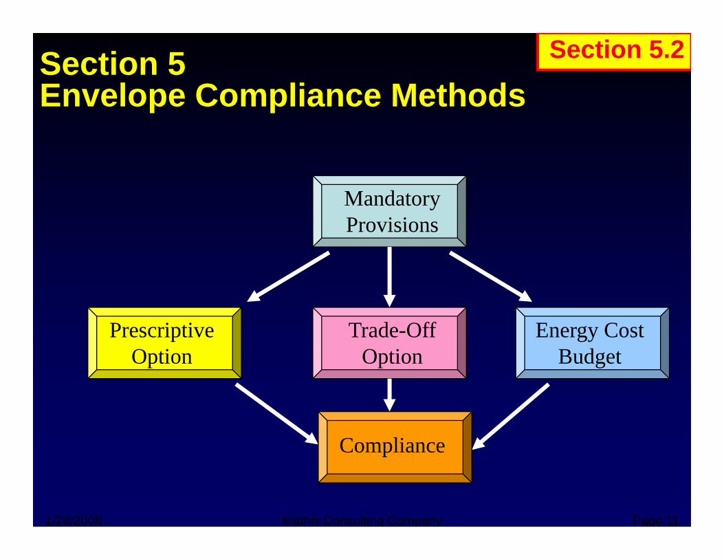
Section 5Envelope Compliance Methods
Section 5.2
Envelope Compliance Methods
Mandatory Provisions
Prescriptive Option
Trade-Off Option
Energy Cost Budget
Compliance
1/28/2008 Mathis Consulting Company Page 11
p
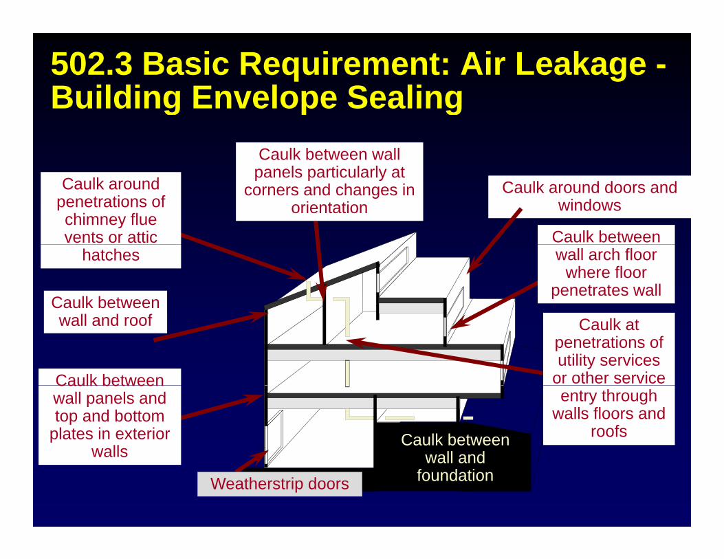
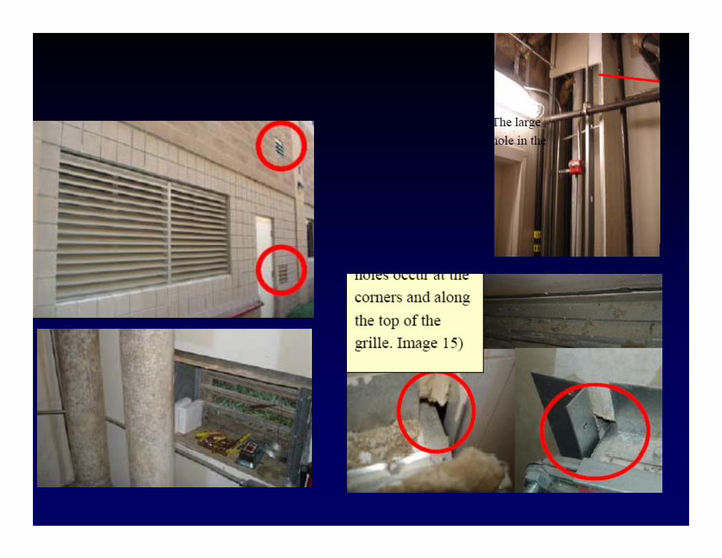
502.3 Basic Requirement: Air Leakage -Building Envelope SealingBuilding Envelope Sealing
Caulk between wall panels particularly at
Caulk around doors and windows
Caulk between
panels particularly at corners and changes in
orientationCaulk around
penetrations of chimney flue vents or attic
wall arch floor where floor
penetrates wallCaulk between
ll d f
hatches
Caulk between
Caulk at penetrations of utility services
or other service
wall and roof
Caulk between wall and
Caulk between wall panels and top and bottom
plates in exterior walls
entry through walls floors and
roofswall and
foundationWeatherstrip doors
walls
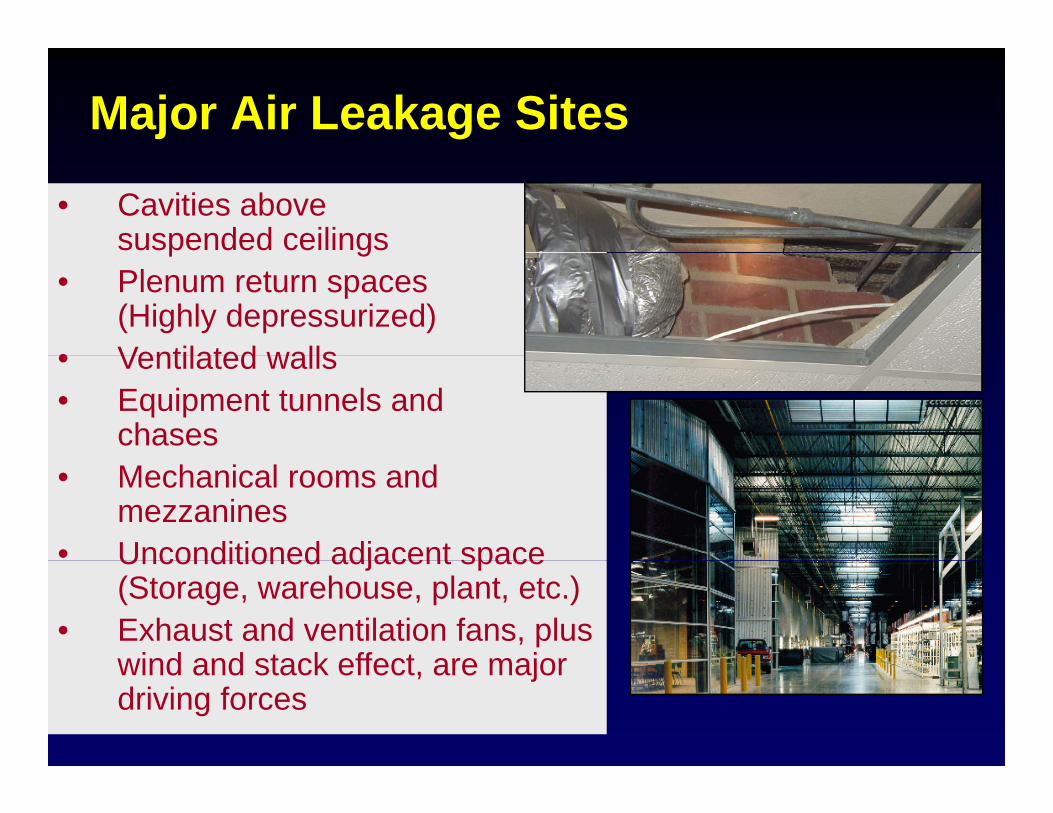
Major Air Leakage Sites
• Cavities above suspended ceilings
• Cavities above suspended ceilingsp g
• Plenum return spaces (Highly depressurized)
• Ventilated walls
p g• Plenum return spaces
(Highly depressurized)• Ventilated walls• Ventilated walls• Equipment tunnels and
chases
• Ventilated walls• Equipment tunnels and
chases• Mechanical rooms and
mezzanines• Unconditioned adjacent space
• Mechanical rooms and mezzanines
• Unconditioned adjacent spaceUnconditioned adjacent space (Storage, warehouse, plant, etc.)
• Exhaust and ventilation fans, plus wind and stack effect are major
Unconditioned adjacent space (Storage, warehouse, plant, etc.)
• Exhaust and ventilation fans, plus wind and stack effect are majorwind and stack effect, are major driving forceswind and stack effect, are major driving forces
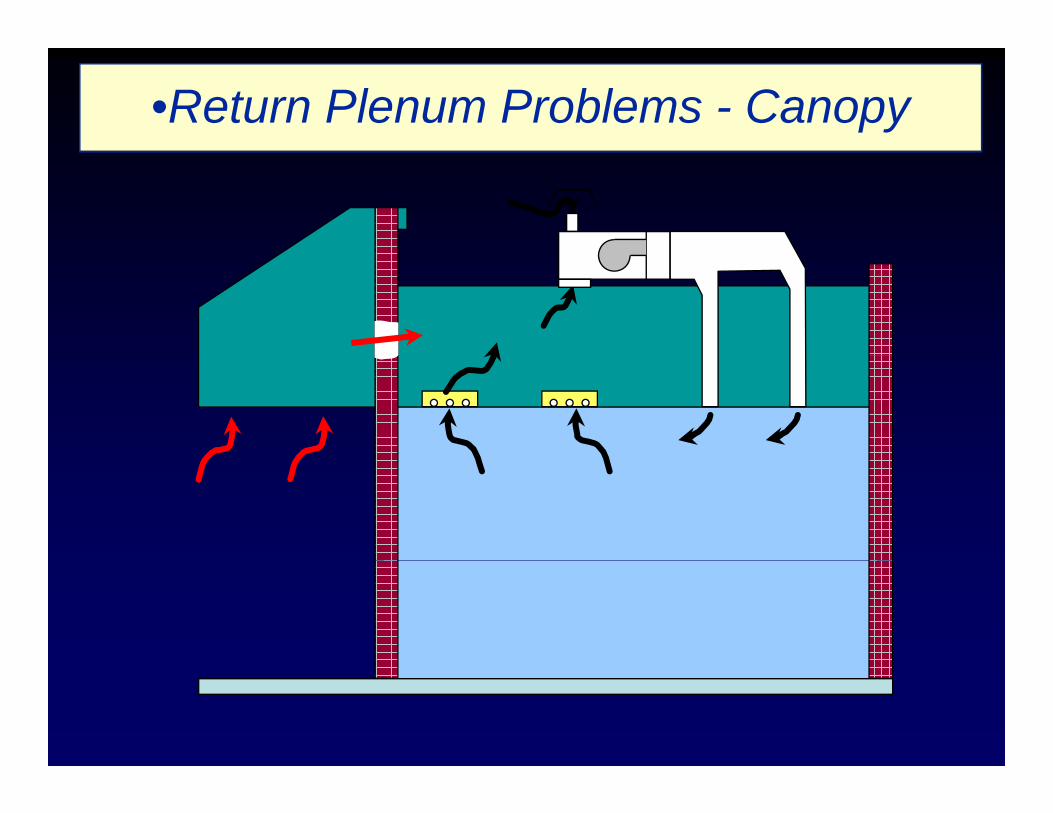
•Return Plenum Problems - Canopy
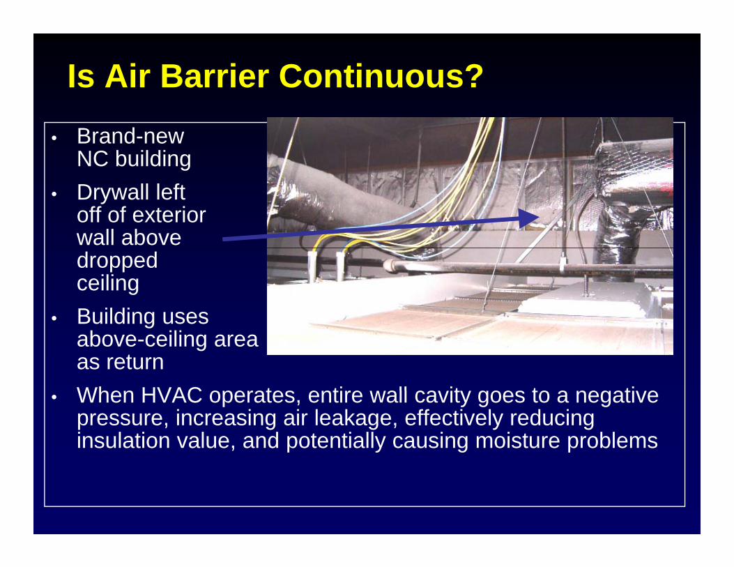
Is Air Barrier Continuous?• Brand-new
NC building• Drywall left
off of exteriorwall abovedropped ceiling
• Building uses• Building usesabove-ceiling areaas returnWhen HVAC operates entire all ca it goes to a negati e• When HVAC operates, entire wall cavity goes to a negative pressure, increasing air leakage, effectively reducing insulation value, and potentially causing moisture problems
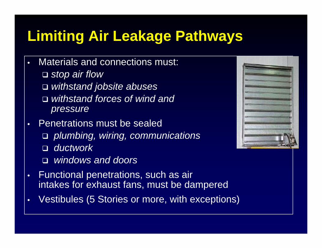
Limiting Air Leakage Pathways• Materials and connections must:
stop air flowstop air flowwithstand jobsite abuseswithstand forces of wind and pressurepressure
• Penetrations must be sealedplumbing, wiring, communicationsp g, g,ductworkwindows and doors
F i l i h i• Functional penetrations, such as air intakes for exhaust fans, must be dampered
• Vestibules (5 Stories or more, with exceptions)Vestibules (5 Stories or more, with exceptions)
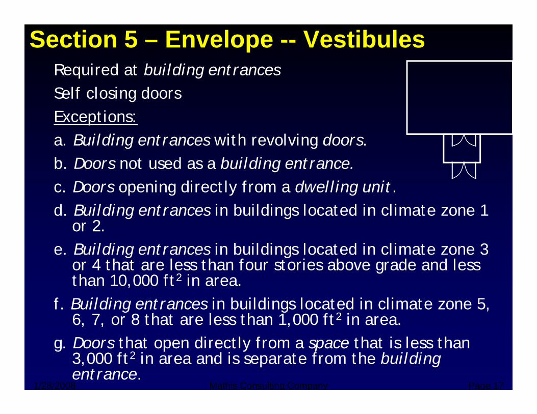
Section 5 – Envelope -- VestibulesRequired at building entrancesq gSelf closing doorsExceptions:a. Building entrances with revolving doors.b. Doors not used as a building entrance.
D i di l f d lli ic. Doors opening directly from a dwelling unit.d. Building entrances in buildings located in climate zone 1
or 2.e. Building entrances in buildings located in climate zone 3
or 4 that are less than four stories above grade and less than 10,000 ft2 in area.than 10,000 ft in area.
f. Building entrances in buildings located in climate zone 5, 6, 7, or 8 that are less than 1,000 ft2 in area. D th t di tl f th t i l th
1/28/2008 Mathis Consulting Company Page 17
g. Doors that open directly from a space that is less than 3,000 ft2 in area and is separate from the building entrance.
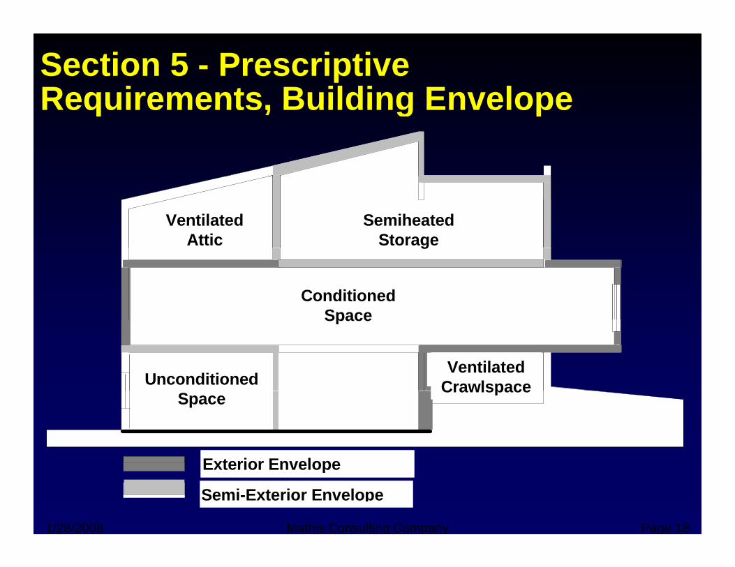
Section 5 - Prescriptive Requirements Building EnvelopeRequirements, Building Envelope
VentilatedAttic
SemiheatedStorageg
ConditionedSpaceSpace
VentilatedCrawlspaceUnconditioned Crawlspace
Exterior Envelope
Space
1/28/2008 Mathis Consulting Company Page 18
Exterior Envelope
Semi-Exterior Envelope
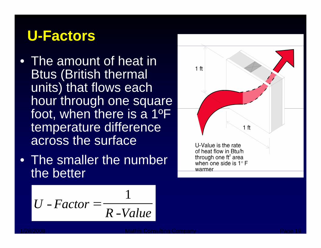
U-Factors• The amount of heat in
Btus (British thermalBtus (British thermal units) that flows each hour through one square foot, when there is a 1ºF temperature difference across the surfaceacross the surface
• The smaller the number the betterthe better
U F t1
1/28/2008 Mathis Consulting Company Page 19
U FactorR Value
- =-
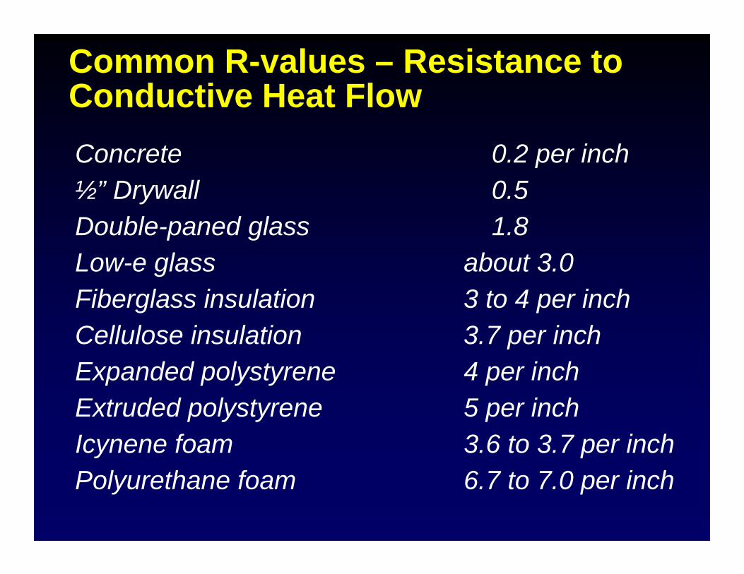
Common R-values – Resistance to Conductive Heat FlowConductive Heat FlowConcrete 0.2 per inch½” Drywall 0.5Double-paned glass 1.8Low-e glass about 3.0Fiberglass insulation 3 to 4 per inchCellulose insulation 3.7 per inchExpanded polystyrene 4 per inchExtruded polystyrene 5 per inchIcynene foam 3.6 to 3.7 per inchPolyurethane foam 6.7 to 7.0 per inch
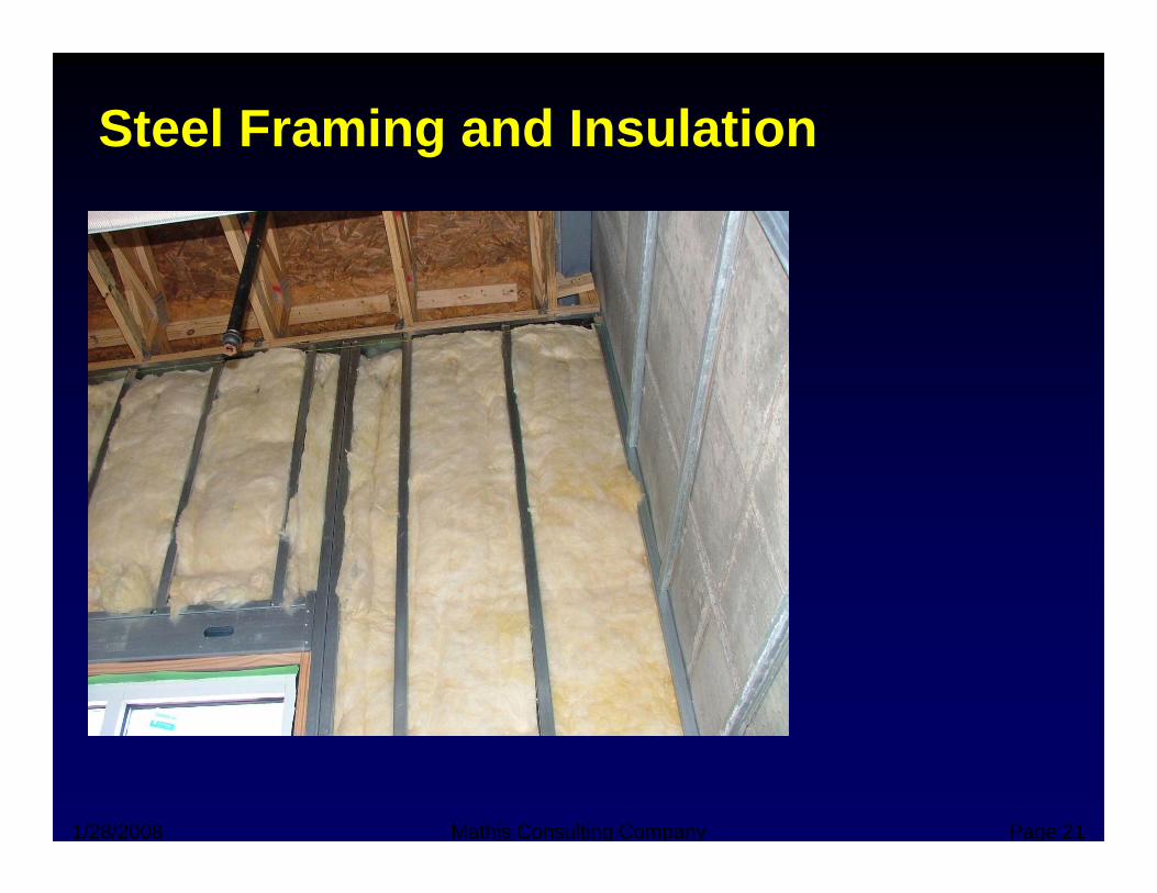
Steel Framing and Insulation
1/28/2008 Mathis Consulting Company Page 21
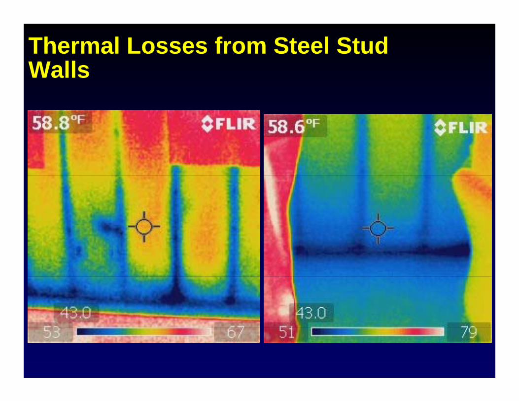
Thermal Losses from Steel Stud WallsWalls
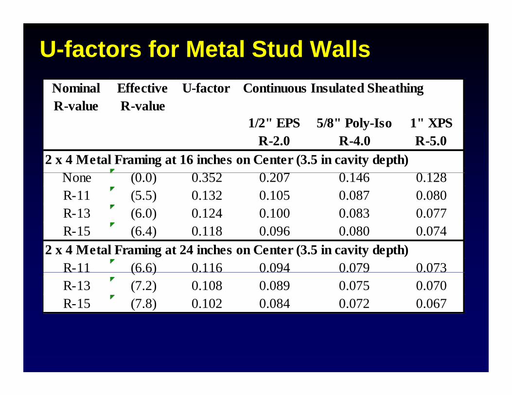
U-factors for Metal Stud WallsNominal R-value
Effective R-value
U-factor Continuous Insulated Sheathing
1/2" EPS 5/8" Poly Iso 1" XPS1/2 EPS 5/8 Poly-Iso 1 XPSR-2.0 R-4.0 R-5.0
2 x 4 Metal Framing at 16 inches on Center (3.5 in cavity depth)(0 0) 0 3 2 0 20 0 146 0 128None (0.0) 0.352 0.207 0.146 0.128
R-11 (5.5) 0.132 0.105 0.087 0.080R-13 (6.0) 0.124 0.100 0.083 0.077R-15 (6.4) 0.118 0.096 0.080 0.074
2 x 4 Metal Framing at 24 inches on Center (3.5 in cavity depth)R-11 (6.6) 0.116 0.094 0.079 0.073( )R-13 (7.2) 0.108 0.089 0.075 0.070R-15 (7.8) 0.102 0.084 0.072 0.067
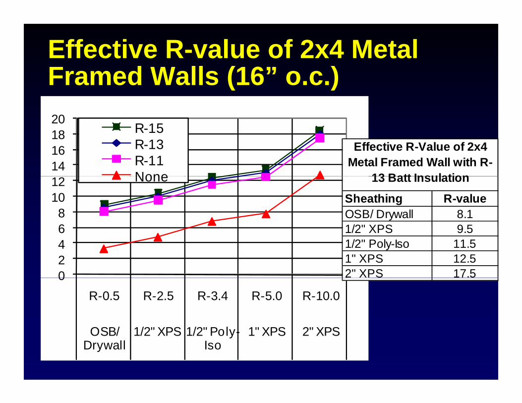
Effective R-value of 2x4 Metal Framed Walls (16” o c )Framed Walls (16 o.c.)20
R 15
141618 R-15
R-13R-11None
Effective R-Value of 2x4 Metal Framed Wall with R-
13 Batt Insulation
68
1012 None
Sheathing R-valueOSB/ Drywall 8.11/2" XPS 9 5
13 Batt Insulation
0246 1/2" XPS 9.5
1/2" Poly-Iso 11.51" XPS 12.52" XPS 17.50
R-0.5 R-2.5 R-3.4 R-5.0 R-10.0
OSB/ 1/2" XPS 1/2" P l 1" XPS 2" XPSOSB/ Drywall
1/2" XPS 1/2" Poly-Iso
1" XPS 2" XPS
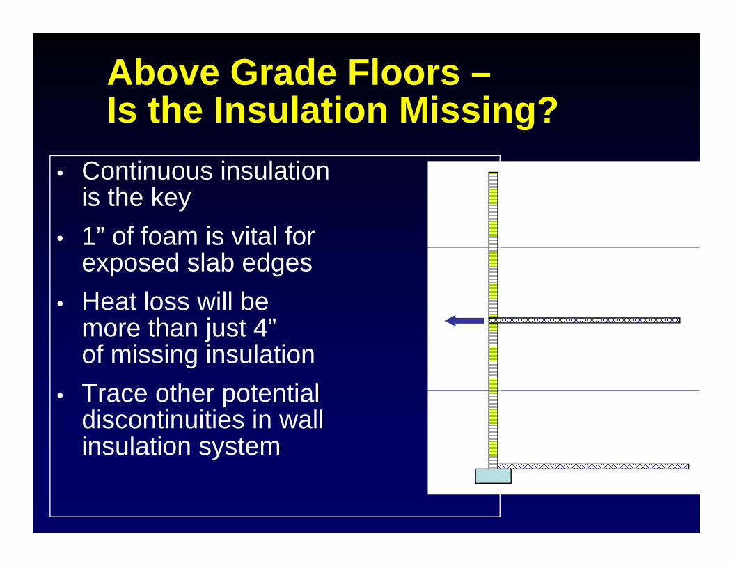
Above Grade Floors –Is the Insulation Missing?Is the Insulation Missing?
• Continuous insulationContinuous insulationis the key
• 1” of foam is vital for exposed slab edges
• Heat loss will be th j t 4”more than just 4”
of missing insulation Trace other potential• Trace other potential discontinuities in wall insulation system
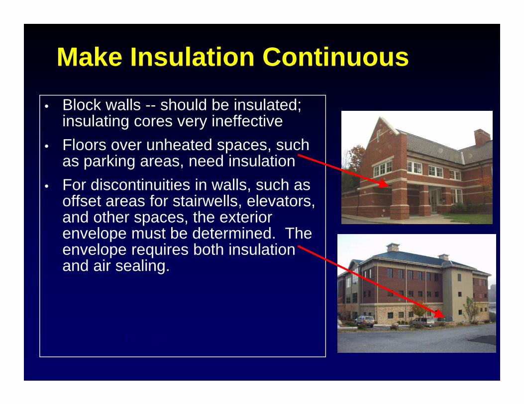
Make Insulation Continuous• Block walls -- should be insulated;
insulating cores very ineffectiveinsulating cores very ineffective• Floors over unheated spaces, such
as parking areas, need insulation• For discontinuities in walls, such as
offset areas for stairwells, elevators, and other spaces, the exterior
l t b d t i d Thenvelope must be determined. The envelope requires both insulation and air sealing.
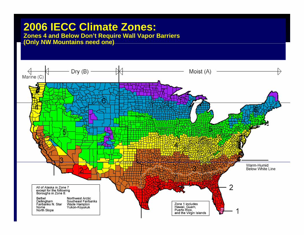
2006 IECC Climate Zones:Zones 4 and Below Don’t Require Wall Vapor Barriers (Only NW Mountains need one)(Only NW Mountains need one)
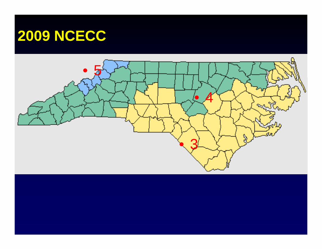
2009 NCECC
• 5
• 4
3• 3
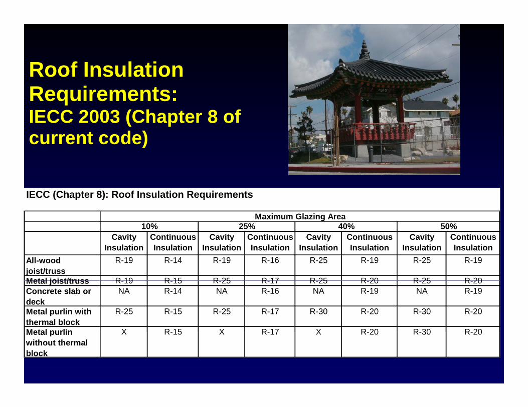
Roof InsulationRoof Insulation Requirements: IECC 2003 (Chapter 8 of (current code)
IECC (Chapter 8): Roof Insulation Requirements
40% 50%Maximum Glazing Area
10% 25%Cavity
InsulationContinuous Insulation
Cavity Insulation
Continuous Insulation
Cavity Insulation
Continuous Insulation
Cavity Insulation
Continuous Insulation
All-wood joist/truss
R-19 R-14 R-19 R-16 R-25 R-19 R-25 R-19
Metal joist/truss R 19 R 15 R 25 R 17 R 25 R 20 R 25 R 20Metal joist/truss R-19 R-15 R-25 R-17 R-25 R-20 R-25 R-20Concrete slab or deck
NA R-14 NA R-16 NA R-19 NA R-19
Metal purlin with thermal block
R-25 R-15 R-25 R-17 R-30 R-20 R-30 R-20
Metal purlin X R 15 X R 17 X R 20 R 30 R 20Metal purlin without thermal block
X R-15 X R-17 X R-20 R-30 R-20
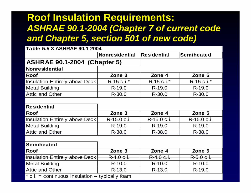
Roof Insulation Requirements:ASHRAE 90.1-2004 (Chapter 7 of current code
d Ch t 5 ti 501 f d )and Chapter 5, section 501 of new code)Table 5.5-3 ASHRAE 90.1-2004
Nonresidential Residential SemiheatedASHRAE 90 1 2004 (Ch t 5)ASHRAE 90.1-2004 (Chapter 5)NonresidentialRoof Zone 3 Zone 4 Zone 5Insulation Entirely above Deck R-15 c.i.* R-15 c.i.* R-15 c.i.*Metal Building R-19.0 R-19.0 R-19.0Attic and Other R-30.0 R-30.0 R-30.0
ResidentialRoof Zone 3 Zone 4 Zone 5Insulation Entirely above Deck R-15.0 c.i. R-15.0 c.i. R-15.0 c.i.Metal Building R-19.0 R-19.0 R-19.0Attic and Other R-38 0 R-38 0 R-38 0Attic and Other R 38.0 R 38.0 R 38.0
SemiheatedRoof Zone 3 Zone 4 Zone 5Insulation Entirely above Deck R-4 0 c i R-4 0 c i R-5 0 c iInsulation Entirely above Deck R-4.0 c.i. R-4.0 c.i. R-5.0 c.i.Metal Building R-10.0 R-10.0 R-10.0Attic and Other R-13.0 R-13.0 R-19.0* c.i. = continuous insulation -- typically foam
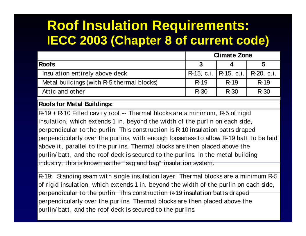
Roof Insulation Requirements: IECC 2003 (Chapter 8 of current code)IECC 2003 (Chapter 8 of current code)
Roofs 3 4 5 Insulation entirely above deck R-15 c i R-15 c i R-20 c i
Climate Zone
Insulation entirely above deck R-15, c.i. R-15, c.i. R-20, c.i. Metal buildings (with R-5 thermal blocks) R-19 R-19 R-19 Attic and other R-30 R-30 R-30
Roofs for Metal Buildings:Roofs for Metal Buildings:R-19 + R-10 Filled cavity roof -- Thermal blocks are a minimum, R-5 of rigid insulation, which extends 1 in. beyond the width of the purlin on each side, perpendicular to the purlin. This construction is R-10 insulation batts draped p p p pperpendicularly over the purlins, with enough looseness to allow R-19 batt to be laid above it, parallel to the purlins. Thermal blocks are then placed above the purlin/batt, and the roof deck is secured to the purlins. In the metal building industry this is known as the “sag and bag” insulation systemindustry, this is known as the sag and bag insulation system.
R-19: Standing seam with single insulation layer. Thermal blocks are a minimum R-5 of rigid insulation, which extends 1 in. beyond the width of the purlin on each side, perpendicular to the purlin This construction R 19 insulation batts draped perpendicular to the purlin. This construction R-19 insulation batts draped perpendicularly over the purlins. Thermal blocks are then placed above the purlin/batt, and the roof deck is secured to the purlins.
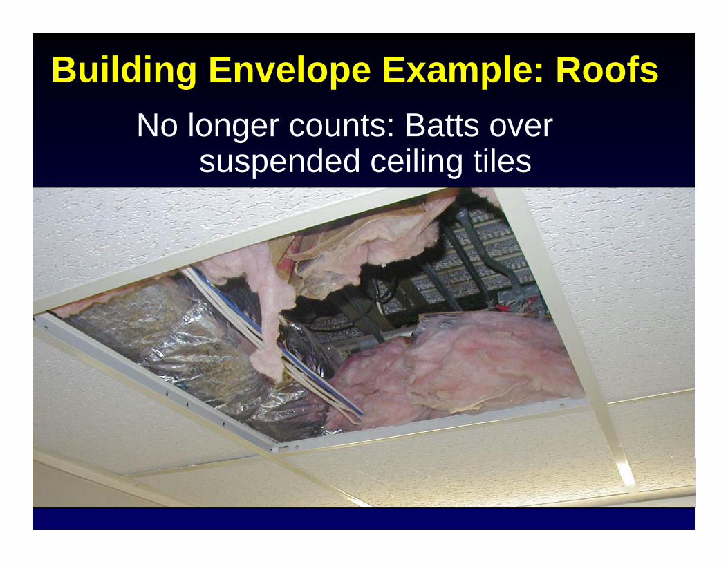
Building Envelope Example: RoofsNo longer counts: Batts over
suspended ceiling tilesp g
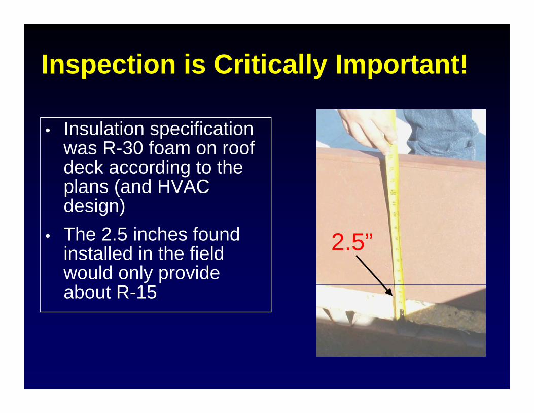
Inspection is Critically Important!p y p
• Insulation specification• Insulation specification was R-30 foam on roof deck according to the
l ( d HVACplans (and HVAC design)The 2 5 inches found 2 ”• The 2.5 inches found installed in the field would only provide
2.5”
about R-15
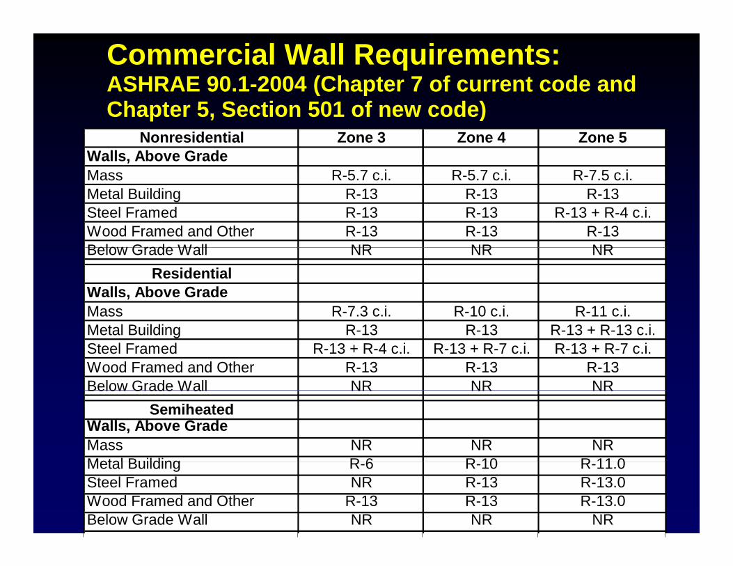
Commercial Wall Requirements:ASHRAE 90.1-2004 (Chapter 7 of current code and Ch t 5 S ti 501 f d )Chapter 5, Section 501 of new code)
Nonresidential Zone 3 Zone 4 Zone 5Walls, Above GradeMass R-5 7 c i R-5 7 c i R-7 5 c iMass R-5.7 c.i. R-5.7 c.i. R-7.5 c.i.Metal Building R-13 R-13 R-13Steel Framed R-13 R-13 R-13 + R-4 c.i.Wood Framed and Other R-13 R-13 R-13Below Grade Wall NR NR NRBelow Grade Wall NR NR NR
ResidentialWalls, Above GradeMass R-7.3 c.i. R-10 c.i. R-11 c.i.Metal Building R-13 R-13 R-13 + R-13 c.i.Steel Framed R-13 + R-4 c.i. R-13 + R-7 c.i. R-13 + R-7 c.i.Wood Framed and Other R-13 R-13 R-13Below Grade Wall NR NR NRBelow Grade Wall NR NR NR
SemiheatedWalls, Above GradeMass NR NR NRMetal Building R 6 R 10 R 11 0Metal Building R-6 R-10 R-11.0Steel Framed NR R-13 R-13.0Wood Framed and Other R-13 R-13 R-13.0Below Grade Wall NR NR NR
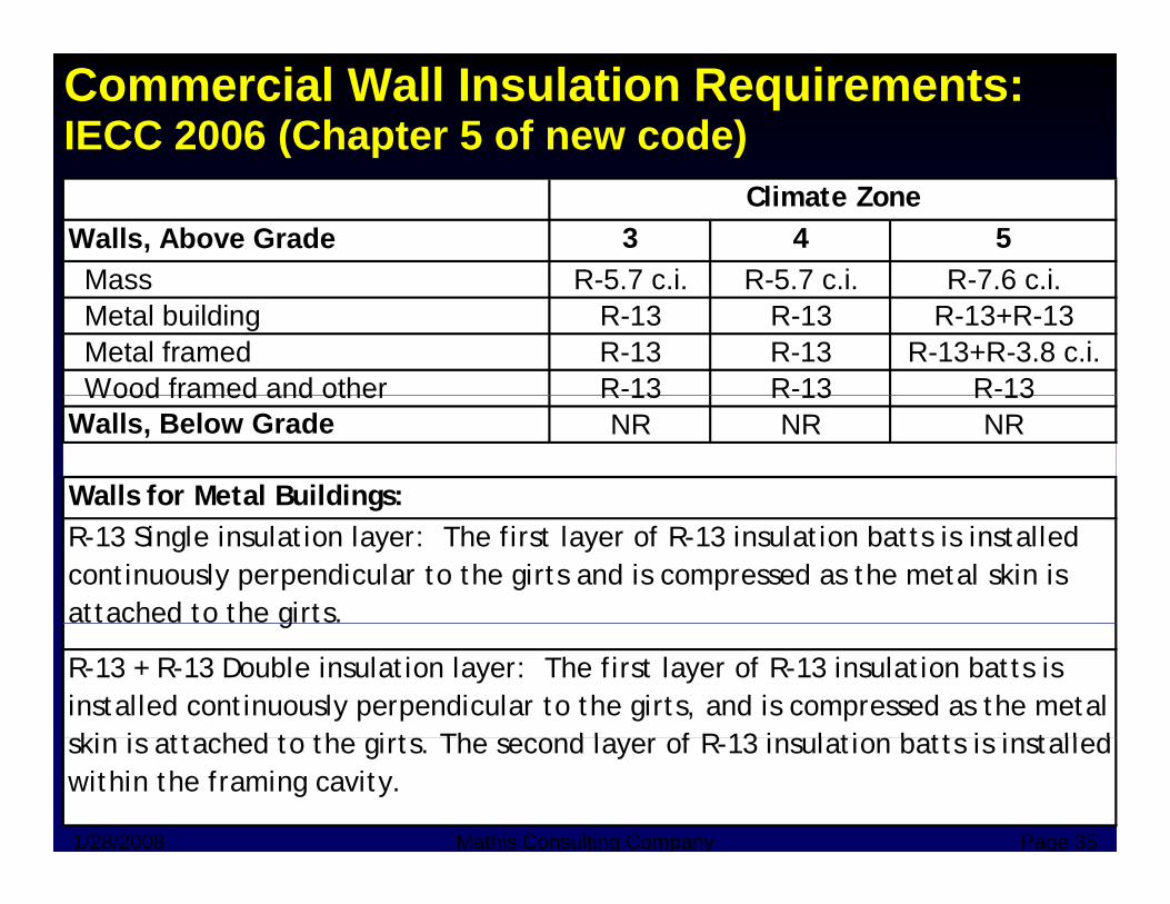
Commercial Wall Insulation Requirements: IECC 2006 (Chapter 5 of new code)
Walls, Above Grade 3 4 5Mass R-5 7 c i R-5 7 c i R-7 6 c i
Climate Zone
Mass R-5.7 c.i. R-5.7 c.i. R-7.6 c.i. Metal building R-13 R-13 R-13+R-13 Metal framed R-13 R-13 R-13+R-3.8 c.i.
Wood framed and other R-13 R-13 R-13 Wood framed and other R 13 R 13 R 13Walls, Below Grade NR NR NR
Walls for Metal Buildings:gR-13 Single insulation layer: The first layer of R-13 insulation batts is installed continuously perpendicular to the girts and is compressed as the metal skin is attached to the girts.
R-13 + R-13 Double insulation layer: The first layer of R-13 insulation batts is installed continuously perpendicular to the girts, and is compressed as the metal ki i tt h d t th gi t Th d l f R 13 i l ti b tt i i t ll d
g
1/28/2008 Mathis Consulting Company Page 35
skin is attached to the girts. The second layer of R-13 insulation batts is installed within the framing cavity.
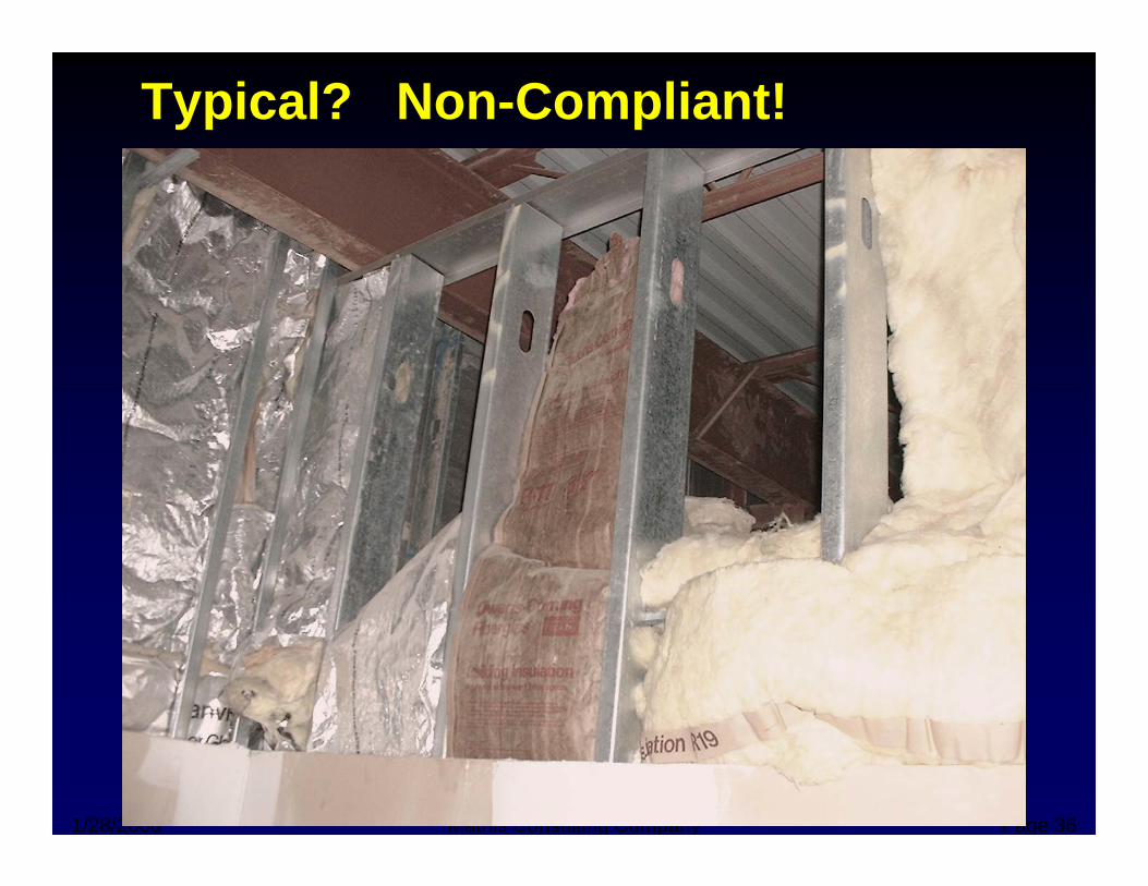
Typical? Non-Compliant!
1/28/2008 Mathis Consulting Company Page 36
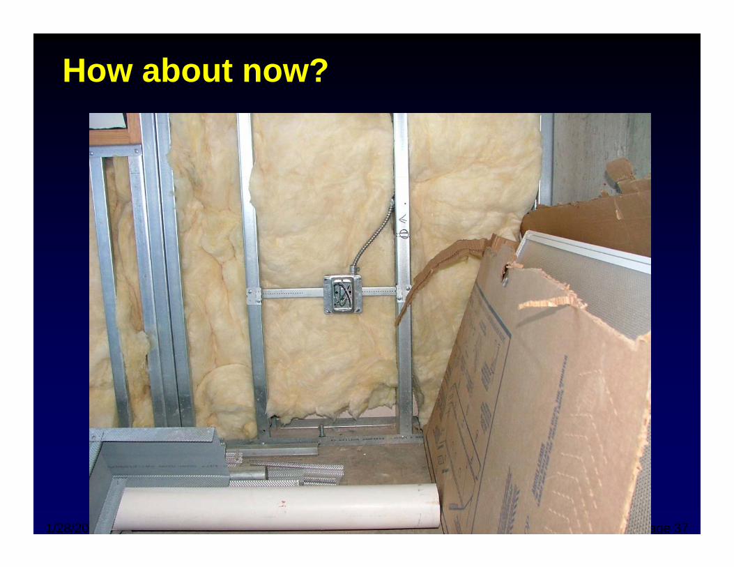
How about now?
1/28/2008 Mathis Consulting Company Page 37
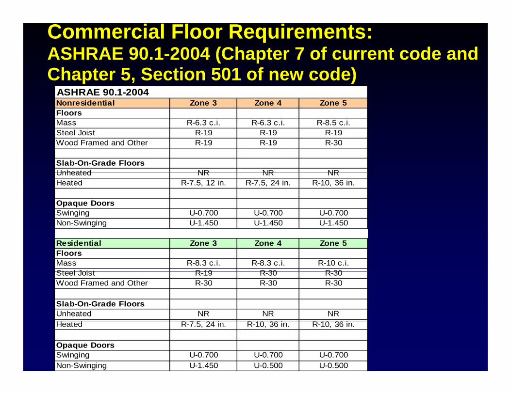
Commercial Floor Requirements:ASHRAE 90.1-2004 (Chapter 7 of current code and Chapter 5 Section 501 of new code)Chapter 5, Section 501 of new code)
ASHRAE 90.1-2004 Nonresidential Zone 3 Zone 4 Zone 5FloorsMass R 6 3 c i R 6 3 c i R 8 5 c iMass R-6.3 c.i. R-6.3 c.i. R-8.5 c.i.Steel Joist R-19 R-19 R-19Wood Framed and Other R-19 R-19 R-30
Slab-On-Grade FloorsUnheated NR NR NRUnheated NR NR NRHeated R-7.5, 12 in. R-7.5, 24 in. R-10, 36 in.
Opaque DoorsSwinging U-0.700 U-0.700 U-0.700Non Swinging U 1 450 U 1 450 U 1 450Non-Swinging U-1.450 U-1.450 U-1.450
Residential Zone 3 Zone 4 Zone 5FloorsMass R-8.3 c.i. R-8.3 c.i. R-10 c.i.Steel Joist R 19 R 30 R 30Steel Joist R-19 R-30 R-30Wood Framed and Other R-30 R-30 R-30
Slab-On-Grade FloorsUnheated NR NR NRH d R 24 i R 10 36 i R 10 36 iHeated R-7.5, 24 in. R-10, 36 in. R-10, 36 in.
Opaque DoorsSwinging U-0.700 U-0.700 U-0.700Non-Swinging U-1.450 U-0.500 U-0.500
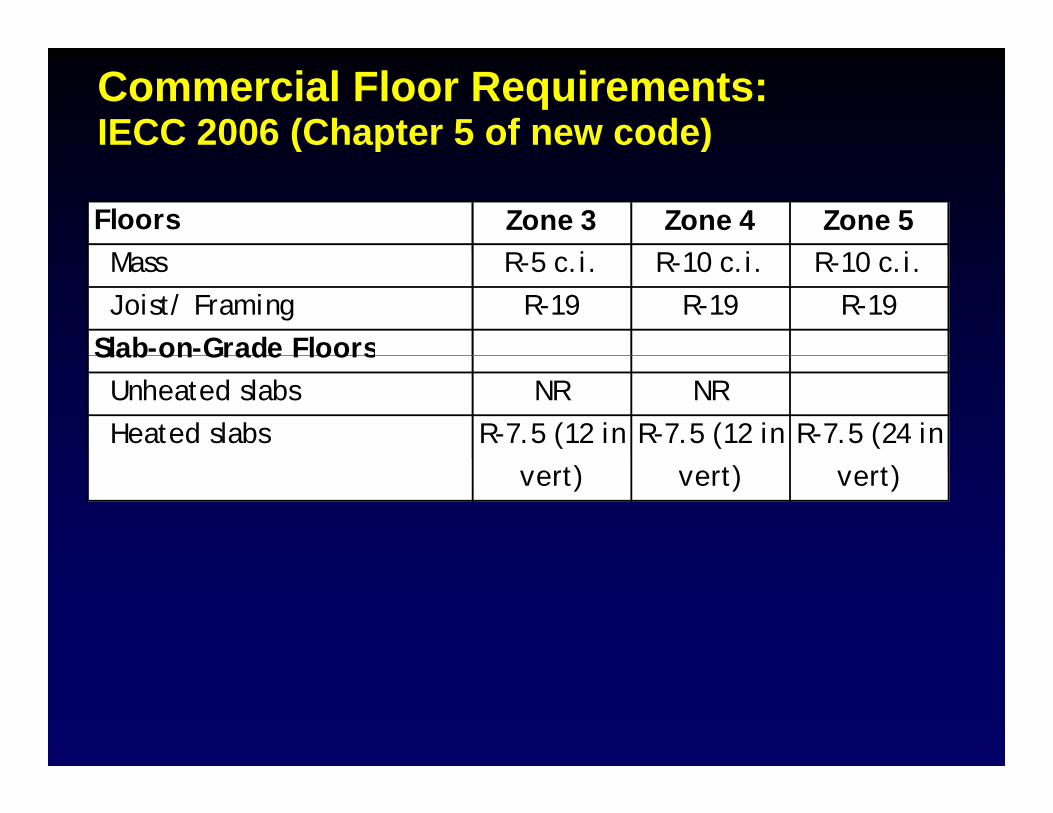
Commercial Floor Requirements:IECC 2006 (Chapter 5 of new code)( p )
Floors Zone 3 Zone 4 Zone 5 M R 5 i R 10 i R 10 i Mass R-5 c.i. R-10 c.i. R-10 c.i. Joist/ Framing R-19 R-19 R-19Slab-on-Grade FloorsSlab on Grade Floors Unheated slabs NR NR Heated slabs R-7.5 (12 in R-7.5 (12 in R-7.5 (24 in
vert) vert) vert)
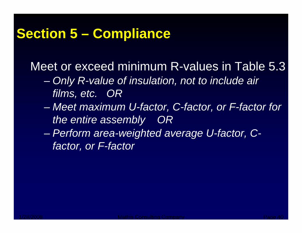
Section 5 – Compliance
Meet or exceed minimum R-values in Table 5.3– Only R-value of insulation, not to include air
films, etc. OR– Meet maximum U-factor, C-factor, or F-factor for
the entire assembly ORPerform area weighted average U factor C– Perform area-weighted average U-factor, C-factor, or F-factor
1/28/2008 Mathis Consulting Company Page 40
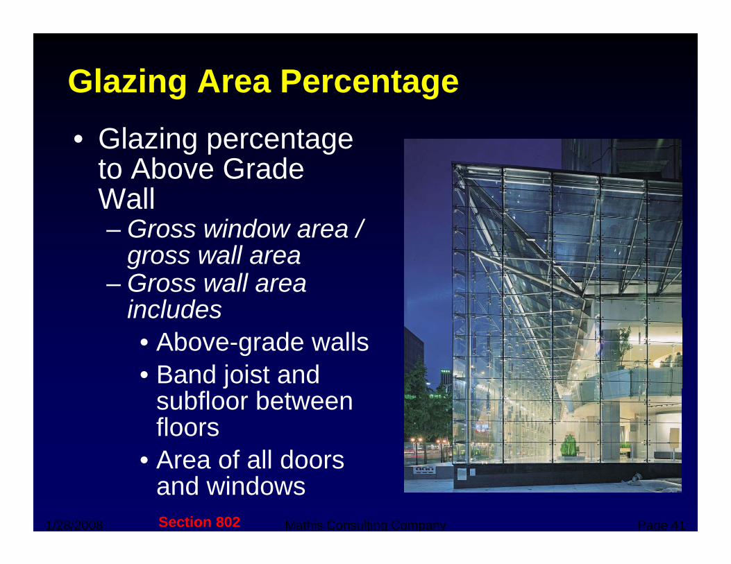
Glazing Area Percentage• Glazing percentage
to Above Gradeto Above Grade Wall– Gross window area /
llgross wall area – Gross wall area
includesincludes• Above-grade walls• Band joist and
subfloor between floors
• Area of all doors
1/28/2008 Mathis Consulting Company Page 41
• Area of all doors and windowsSection 802
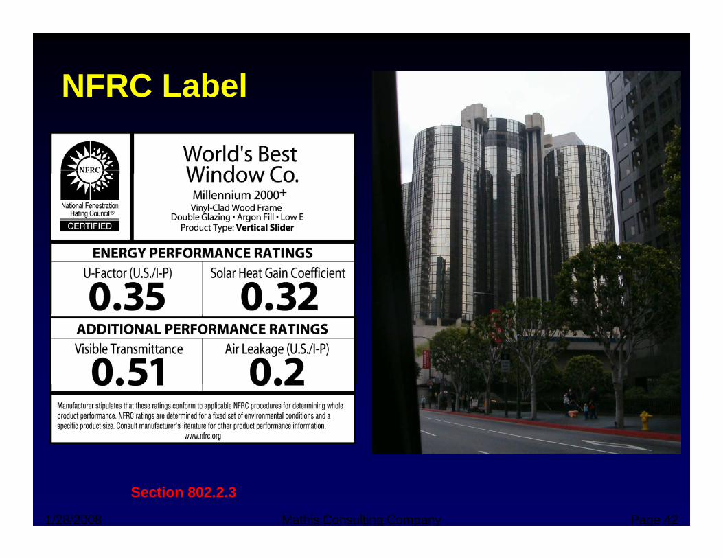
NFRC Label
1/28/2008 Mathis Consulting Company Page 42
Section 802.2.3
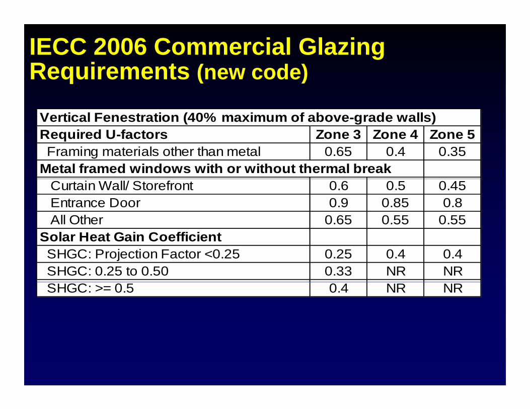
IECC 2006 Commercial Glazing Requirements (new code)Requirements (new code)
Vertical Fenestration (40% maximum of above-grade walls)Required U-factors Zone 3 Zone 4 Zone 5 Framing materials other than metal 0.65 0.4 0.35Metal framed windows with or without thermal break Curtain Wall/ Storefront 0.6 0.5 0.45 Entrance Door 0.9 0.85 0.8 All Other 0.65 0.55 0.55Solar Heat Gain Coefficient SHGC: Projection Factor <0.25 0.25 0.4 0.4 SHGC: 0.25 to 0.50 0.33 NR NR SHGC: >= 0.5 0.4 NR NR
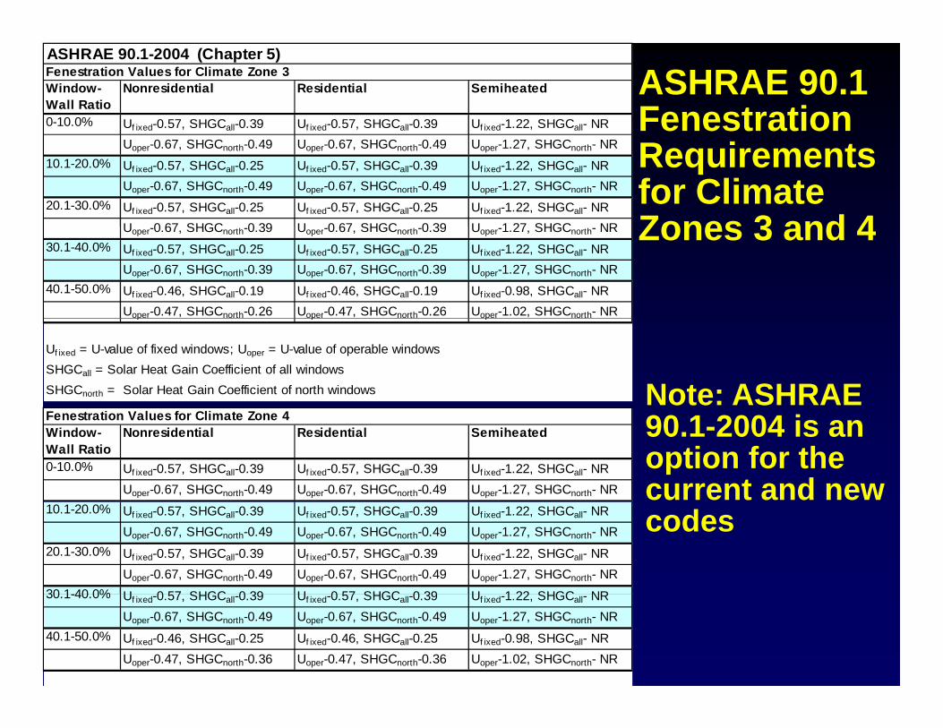
ASHRAE 90.1 Fenestration
ASHRAE 90.1-2004 (Chapter 5)Fenestration Values for Climate Zone 3Window-Wall Ratio
Nonresidential Residential Semiheated
0-10.0% Uf ixed-0.57, SHGCall-0.39 Uf ixed-0.57, SHGCall-0.39 Uf ixed-1.22, SHGCall- NR
Requirements for Climate Zones 3 and 4
Uoper-0.67, SHGCnorth-0.49 Uoper-0.67, SHGCnorth-0.49 Uoper-1.27, SHGCnorth- NR10.1-20.0% Uf ixed-0.57, SHGCall-0.25 Uf ixed-0.57, SHGCall-0.39 Uf ixed-1.22, SHGCall- NR
Uoper-0.67, SHGCnorth-0.49 Uoper-0.67, SHGCnorth-0.49 Uoper-1.27, SHGCnorth- NR20.1-30.0% Uf ixed-0.57, SHGCall-0.25 Uf ixed-0.57, SHGCall-0.25 Uf ixed-1.22, SHGCall- NR
U 0 67 SHGC 0 39 U 0 67 SHGC 0 39 U 1 27 SHGC NR Zones 3 and 4Uoper-0.67, SHGCnorth-0.39 Uoper-0.67, SHGCnorth-0.39 Uoper-1.27, SHGCnorth- NR30.1-40.0% Uf ixed-0.57, SHGCall-0.25 Uf ixed-0.57, SHGCall-0.25 Uf ixed-1.22, SHGCall- NR
Uoper-0.67, SHGCnorth-0.39 Uoper-0.67, SHGCnorth-0.39 Uoper-1.27, SHGCnorth- NR40.1-50.0% Uf ixed-0.46, SHGCall-0.19 Uf ixed-0.46, SHGCall-0.19 Uf ixed-0.98, SHGCall- NR
Uoper-0.47, SHGCnorth-0.26 Uoper-0.47, SHGCnorth-0.26 Uoper-1.02, SHGCnorth- NRp p p
Uf ixed = U-value of fixed windows; Uoper = U-value of operable windowsSHGCall = Solar Heat Gain Coefficient of all windowsSHGCnorth = Solar Heat Gain Coefficient of north windows Note: ASHRAE Fenestration Values for Climate Zone 4Window-Wall Ratio
Nonresidential Residential Semiheated
0-10.0% Uf ixed-0.57, SHGCall-0.39 Uf ixed-0.57, SHGCall-0.39 Uf ixed-1.22, SHGCall- NRUoper-0.67, SHGCnorth-0.49 Uoper-0.67, SHGCnorth-0.49 Uoper-1.27, SHGCnorth- NR
90.1-2004 is an option for the current and new
10.1-20.0% Uf ixed-0.57, SHGCall-0.39 Uf ixed-0.57, SHGCall-0.39 Uf ixed-1.22, SHGCall- NRUoper-0.67, SHGCnorth-0.49 Uoper-0.67, SHGCnorth-0.49 Uoper-1.27, SHGCnorth- NR
20.1-30.0% Uf ixed-0.57, SHGCall-0.39 Uf ixed-0.57, SHGCall-0.39 Uf ixed-1.22, SHGCall- NRUoper-0.67, SHGCnorth-0.49 Uoper-0.67, SHGCnorth-0.49 Uoper-1.27, SHGCnorth- NR
30 1 40 0% U 0 57 SHGC 0 39 U 0 57 SHGC 0 39 U 1 22 SHGC NR
codes
30.1-40.0% Uf ixed-0.57, SHGCall-0.39 Uf ixed-0.57, SHGCall-0.39 Uf ixed-1.22, SHGCall- NRUoper-0.67, SHGCnorth-0.49 Uoper-0.67, SHGCnorth-0.49 Uoper-1.27, SHGCnorth- NR
40.1-50.0% Uf ixed-0.46, SHGCall-0.25 Uf ixed-0.46, SHGCall-0.25 Uf ixed-0.98, SHGCall- NRUoper-0.47, SHGCnorth-0.36 Uoper-0.47, SHGCnorth-0.36 Uoper-1.02, SHGCnorth- NR
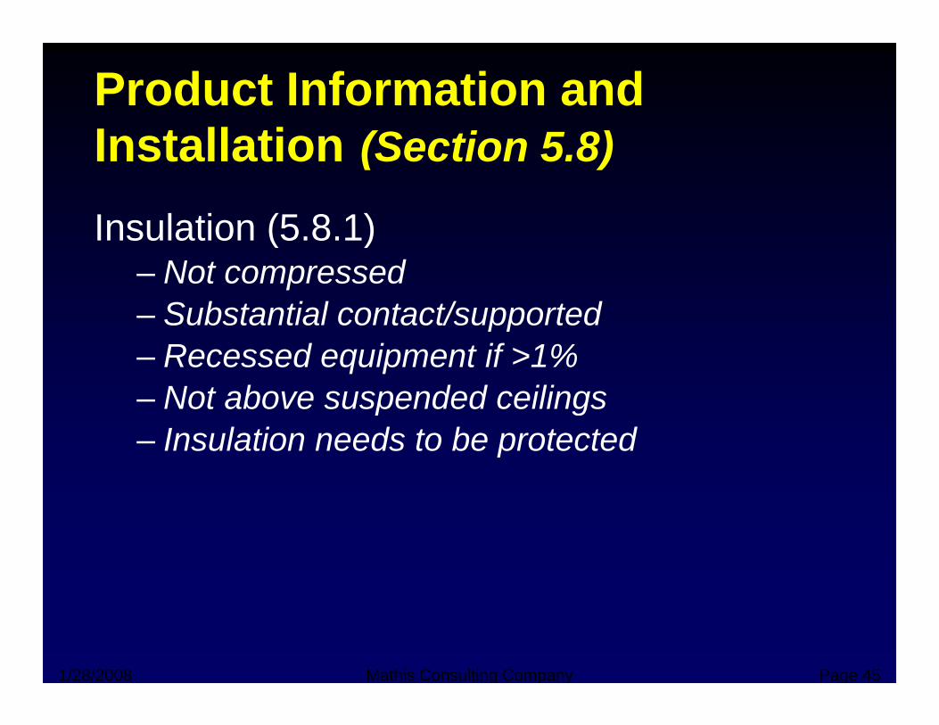
Product Information and I t ll ti (S ti 5 8)Installation (Section 5.8)
Insulation (5 8 1)Insulation (5.8.1)– Not compressed– Substantial contact/supported– Substantial contact/supported– Recessed equipment if >1%– Not above suspended ceilingsNot above suspended ceilings– Insulation needs to be protected
1/28/2008 Mathis Consulting Company Page 45
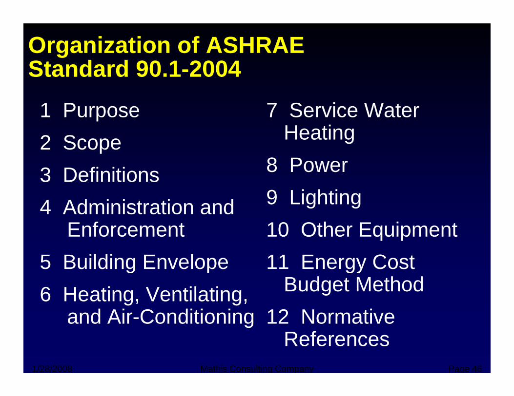
Organization of ASHRAE Standard 90 1-2004Standard 90.1 2004
1 Purpose 7 Service Water 2 Scope3 Definitions
Heating8 Power3 Definitions
4 Administration and E f t
9 Lighting10 Oth E i tEnforcement
5 Building Envelope10 Other Equipment11 Energy Cost g
6 Heating, Ventilating, and Air-Conditioning
gyBudget Method
12 Normative
1/28/2008 Mathis Consulting Company Page 46
and Air Conditioning 12 Normative References
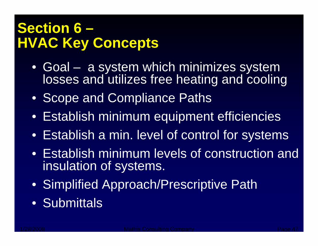
Section 6 –HVAC Key ConceptsHVAC Key Concepts
• Goal – a system which minimizes system l d tili f h ti d lilosses and utilizes free heating and cooling
• Scope and Compliance Paths• Establish minimum equipment efficiencies • Establish a min. level of control for systemsEstablish a min. level of control for systems• Establish minimum levels of construction and
insulation of systems.insulation of systems.• Simplified Approach/Prescriptive Path
Submittals
1/28/2008 Mathis Consulting Company Page 47
• Submittals
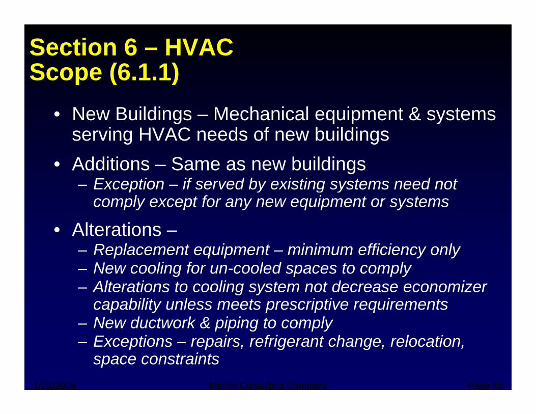
Section 6 – HVACScope (6 1 1)Scope (6.1.1)
• New Buildings – Mechanical equipment & systems i HVAC d f b ildiserving HVAC needs of new buildings
• Additions – Same as new buildingsException if served by existing systems need not– Exception – if served by existing systems need not comply except for any new equipment or systems
• Alterations –Alterations – Replacement equipment – minimum efficiency only– New cooling for un-cooled spaces to comply
Alterations to cooling system not decrease economizer– Alterations to cooling system not decrease economizer capability unless meets prescriptive requirements
– New ductwork & piping to complyE ti i f i t h l ti
1/28/2008 Mathis Consulting Company Page 48
– Exceptions – repairs, refrigerant change, relocation, space constraints
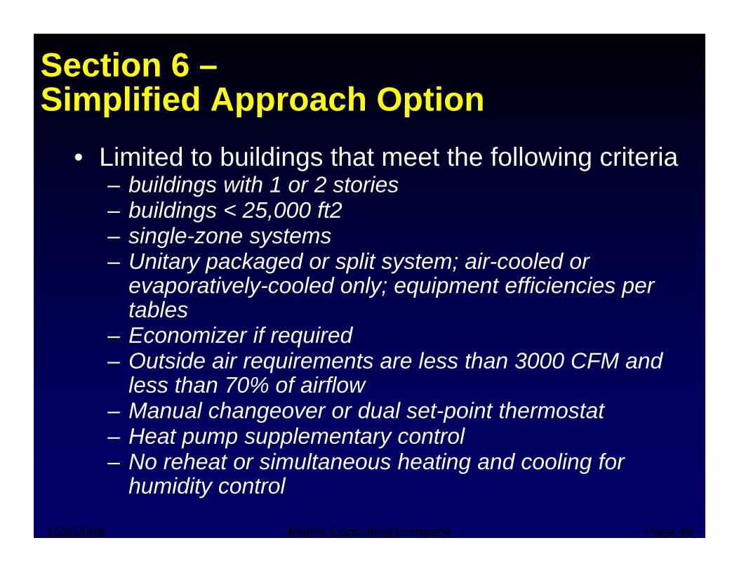
Section 6 –Simplified Approach OptionSimplified Approach Option
• Limited to buildings that meet the following criteriab ildi ith 1 2 t i– buildings with 1 or 2 stories
– buildings < 25,000 ft2– single-zone systems– Unitary packaged or split system; air-cooled or
evaporatively-cooled only; equipment efficiencies per tables
– Economizer if required– Outside air requirements are less than 3000 CFM and
less than 70% of airflow– Manual changeover or dual set-point thermostat– Heat pump supplementary control– No reheat or simultaneous heating and cooling for
1/28/2008 Mathis Consulting Company Page 49
No reheat or simultaneous heating and cooling for humidity control
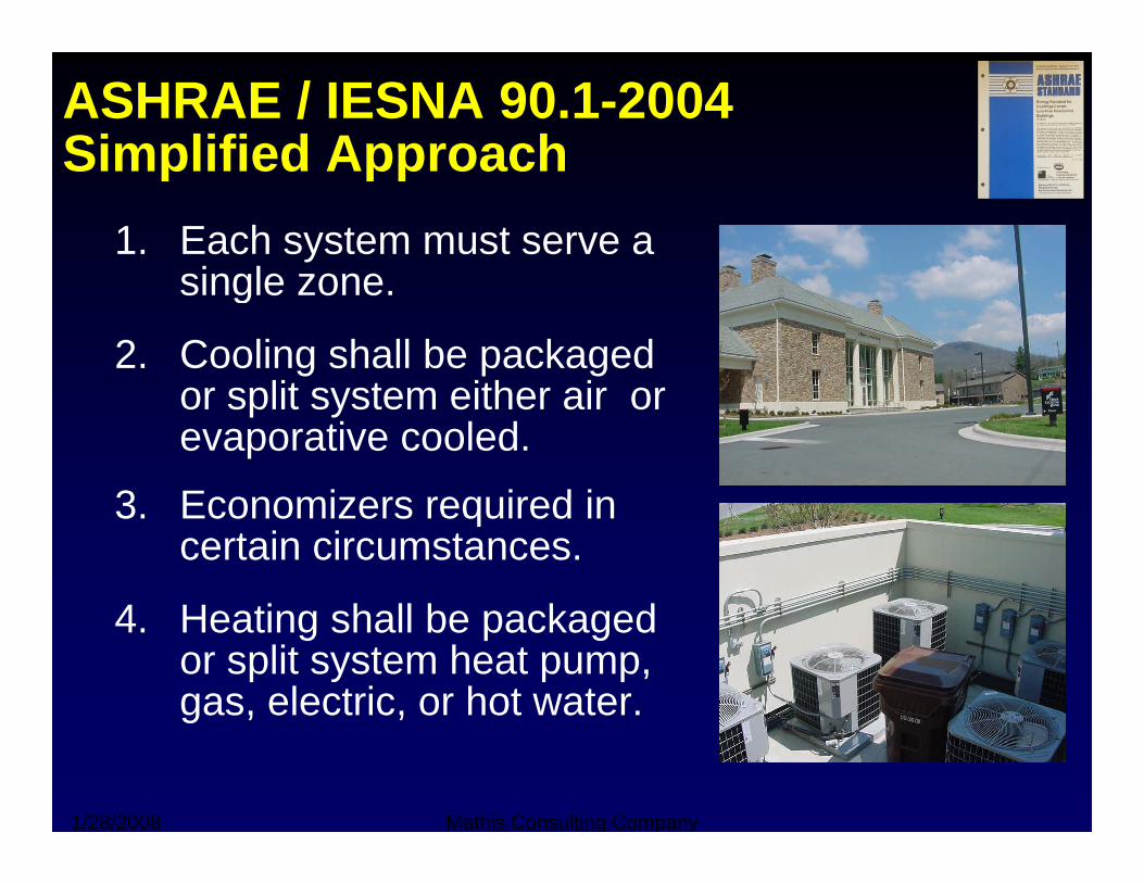
ASHRAE / IESNA 90.1-2004Simplified ApproachSimplified Approach
1. Each system must serve a single zonesingle zone.
2. Cooling shall be packaged lit t ith ior split system either air or
evaporative cooled.
3 Economizers required in3. Economizers required in certain circumstances.
4 H ti h ll b k d4. Heating shall be packaged or split system heat pump, gas, electric, or hot water.
1/28/2008 Mathis Consulting Company
g , ,
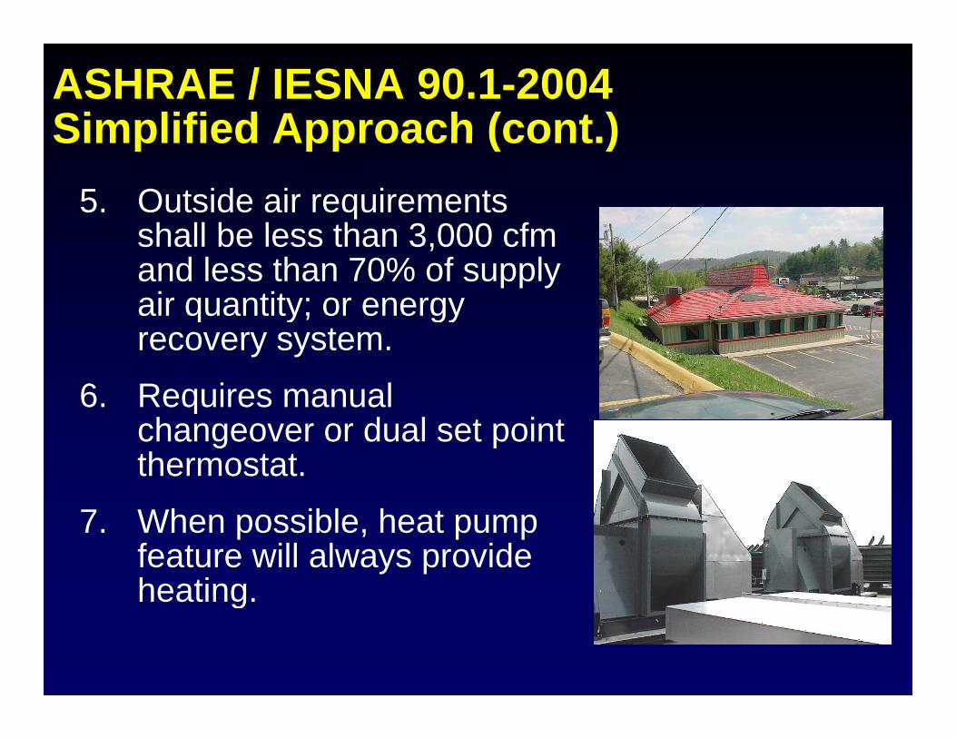
ASHRAE / IESNA 90.1-2004Simplified Approach (cont )Simplified Approach (cont.)
5. Outside air requirements shall be less than 3 000 cfmshall be less than 3,000 cfm and less than 70% of supply air quantity; or energy y gyrecovery system.
6. Requires manual changeover or dual set point thermostat.
7 Wh ibl h7. When possible, heat pump feature will always provide heating.ea g
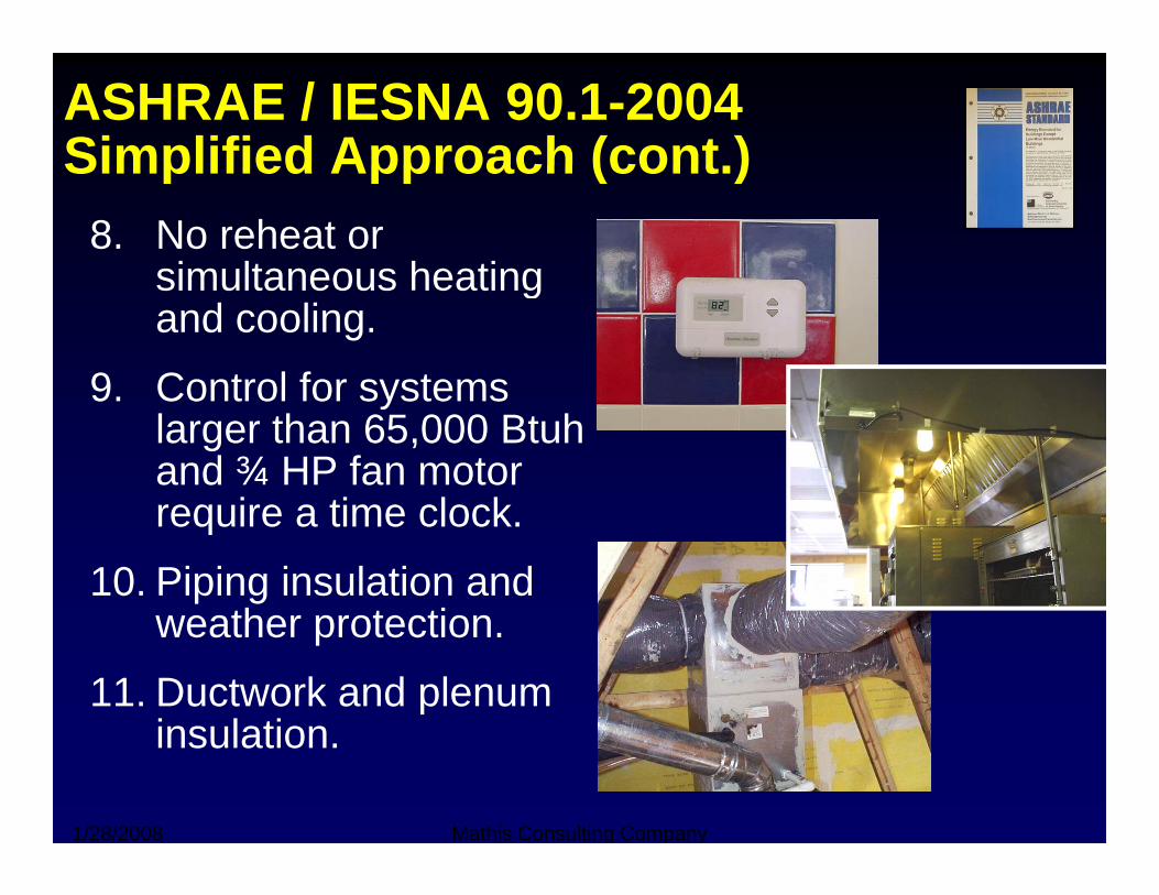
ASHRAE / IESNA 90.1-2004Simplified Approach (cont )Simplified Approach (cont.)
8. No reheat or simultaneous heatingsimultaneous heating and cooling.
9 Control for systems9. Control for systems larger than 65,000 Btuh and ¾ HP fan motor
i ti l krequire a time clock.
10. Piping insulation and weather protectionweather protection.
11. Ductwork and plenum insulation
1/28/2008 Mathis Consulting Company
insulation.
ASHRAE / IESNA 90.1-2004Simplified Approach (cont )Simplified Approach (cont.)
12. Ducted systems air balanced to 10% of design10% of design.
13. Separate thermostats interlocked to prevent simultaneous heating andprevent simultaneous heating and cooling.
14 Exhausts over 300 cfm shall have14. Exhausts over 300 cfm shall have gravity or motor dampers.
15 System greater than 10 000 cfm15. System greater than 10,000 cfm shall have optimum start controls.
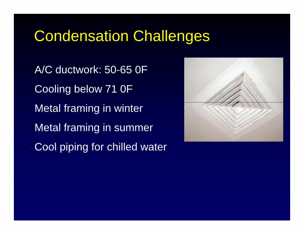
Condensation Challengesg
• A/C ductwork: 50-65 0FA/C ductwork: 50 65 0F
• Cooling below 71 0F
• Metal framing in winter
• Metal framing in summerg
• Cool piping for chilled water
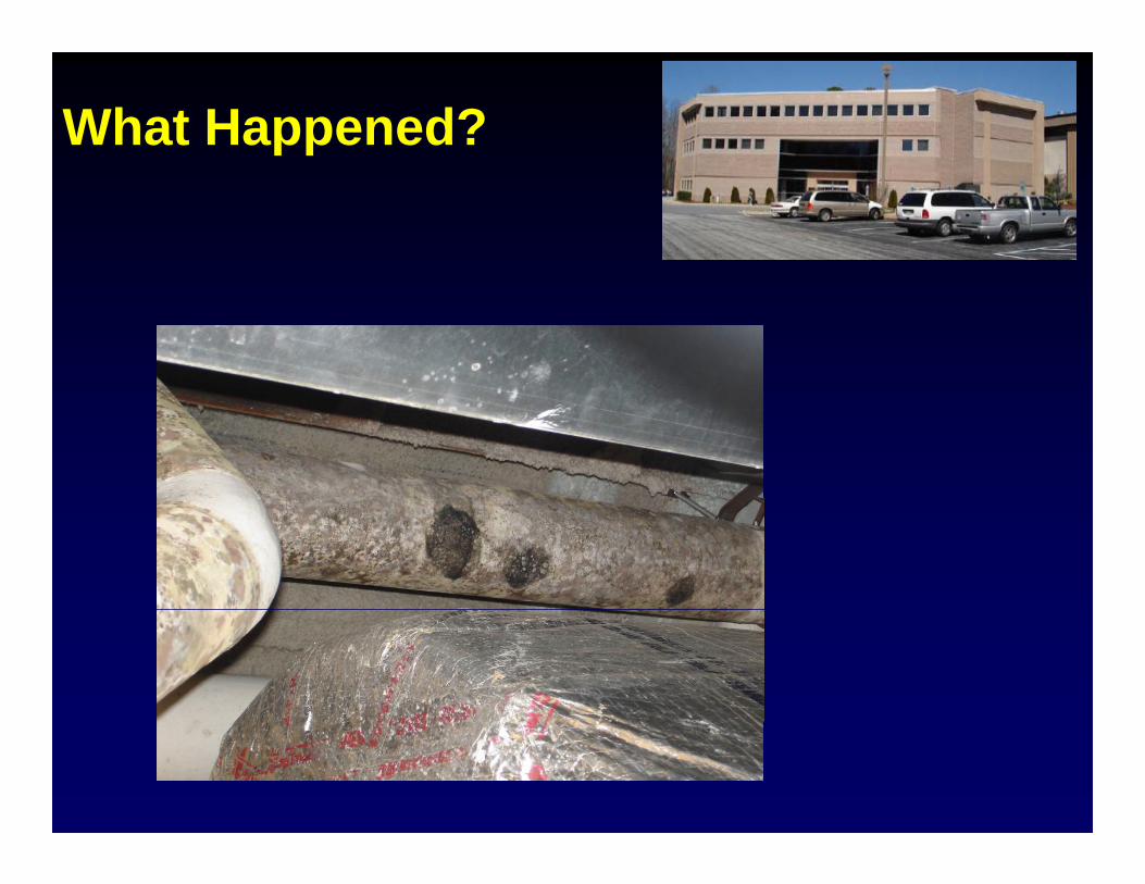
What Happened?
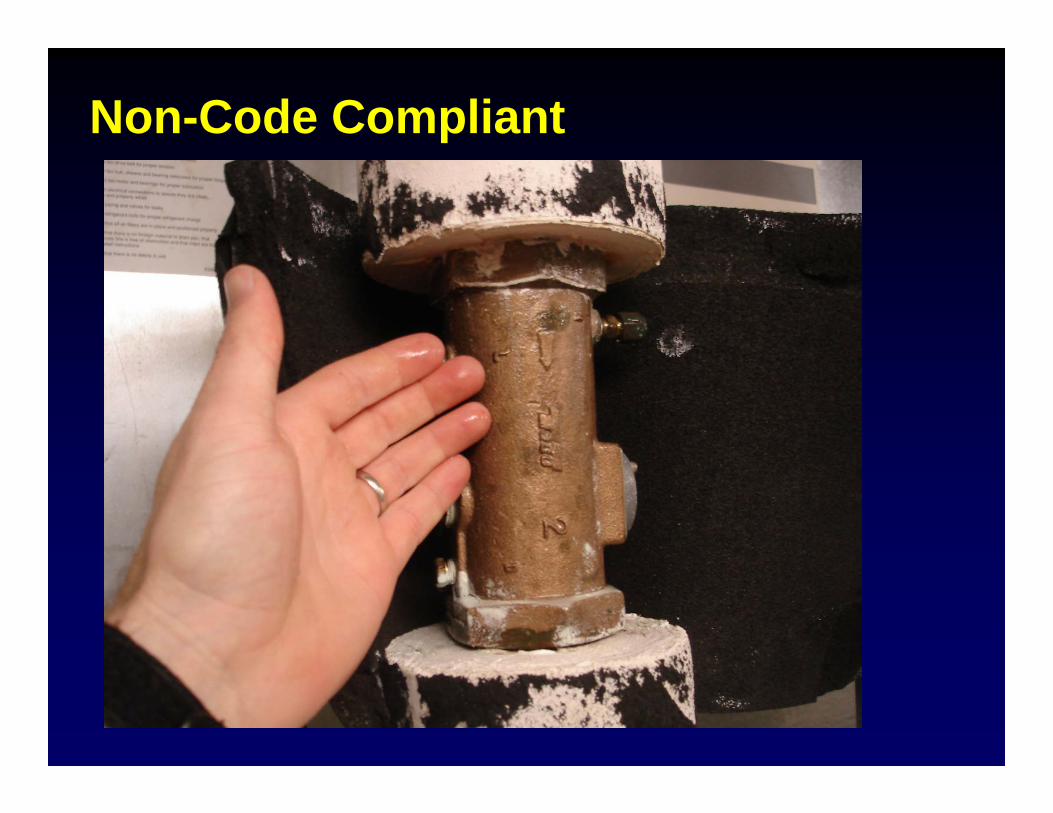
Non-Code Compliant
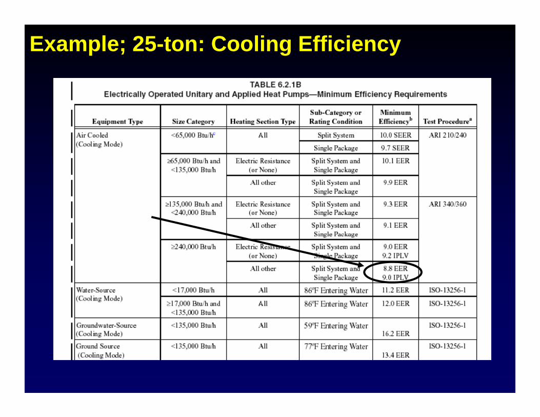
Example; 25-ton: Cooling Efficiency
Cooling efficiency:25 tons = 300 000300,000 Btuh
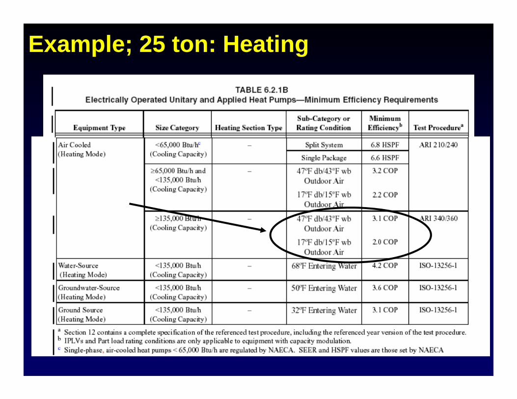
Example; 25 ton: Heating
HeatingHeating efficiency:25 tons = 300,000 Btuh
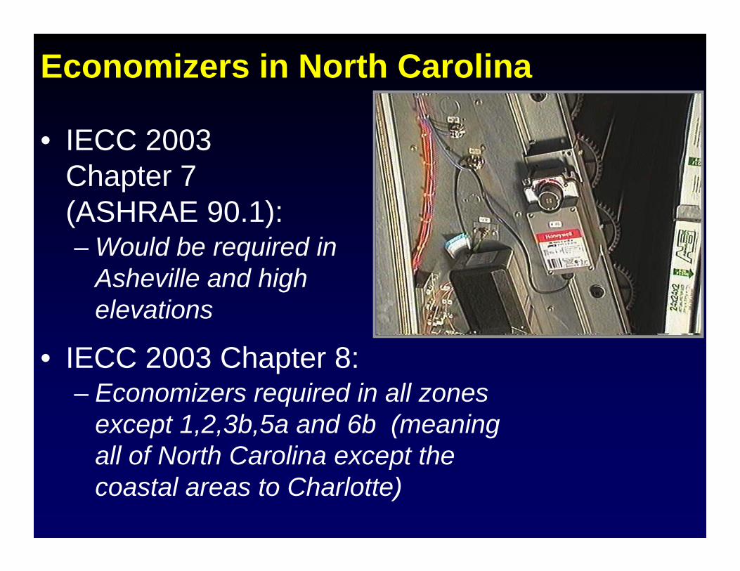
Economizers in North Carolina
• IECC 2003 Chapter 7Chapter 7 (ASHRAE 90.1):– Would be required in– Would be required in
Asheville and high elevations
• IECC 2003 Chapter 8:Economizers required in all zones– Economizers required in all zones except 1,2,3b,5a and 6b (meaning all of North Carolina except the pcoastal areas to Charlotte)
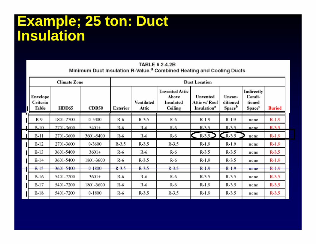
Example; 25 ton: Duct Insulation
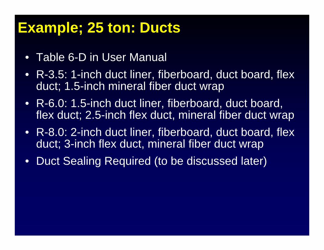
Example; 25 ton: Ducts
• Table 6-D in User Manual• R-3.5: 1-inch duct liner, fiberboard, duct board, flexR 3.5: 1 inch duct liner, fiberboard, duct board, flex
duct; 1.5-inch mineral fiber duct wrap• R-6.0: 1.5-inch duct liner, fiberboard, duct board,
flex duct; 2.5-inch flex duct, mineral fiber duct wrap• R-8.0: 2-inch duct liner, fiberboard, duct board, flex
d t 3 i h fl d t i l fib d tduct; 3-inch flex duct, mineral fiber duct wrap• Duct Sealing Required (to be discussed later)
Example; 25 ton: Other
• Air Balancing – add note to the design drawings or specs calling for balancingdrawings or specs calling for balancing according to ASHRAE 111, NEBB, AABCm or other industry-recognized standardor other industry recognized standard
• Since no fan exceeds 300 cfm, a backdraft d i t i d 6 2 3 3 3damper is not required per 6.2.3.3.3
ASHRAE / IESNA 90.1-2004HVAC Mandatory Provisionsy
• Applies to the Prescriptive Path and the pp pEnergy Cost Budget method
• Requirements address• Requirements address…– Life cycle cost analysis– Equipment efficiencies– Load calculations– Controls
Construction and insulation– Construction and insulation– Completion requirements
Constant vs. Variable Speed SystemsConstant vs. Variable Speed Systems• Constant speed fans and pumps, constant temperature
heating and cooling systems and constant volumeheating and cooling systems and constant volume ventilation and exhaust systems are efficient only at full load conditions.
• Variable systems are efficient at part loads.
• Motors: Multiple speed, modular, variable speed.
• Supply Air: Bypass, variable air volume.
• Supply temperature: Reset based on demand or outdoor airSupply temperature: Reset based on demand or outdoor air temperature.
• Outdoor air: Reset based on occupancy.y
• Primary heating and cooling equipment: staged, modular.
Section 6 Mechanical Equipment Efficiency
Section 6.4
Mechanical Equipment Efficiency
• Air conditioners & Condensing Units• Heat Pumps• Water Chilling Packages – standard conditions• Packaged Terminal and Room Air Conditioners &
Heat PumpsF D t F d U it H t• Furnaces, Duct Furnaces and Unit Heaters
• Boilers• Heat Rejection Equipment
1/28/2008 Mathis Consulting Company Page 67
Section 6 Load CalculationsLoad Calculations
• Load Calculations are required!A k f h !– Ask for them!
1/28/2008 Mathis Consulting Company Page 68
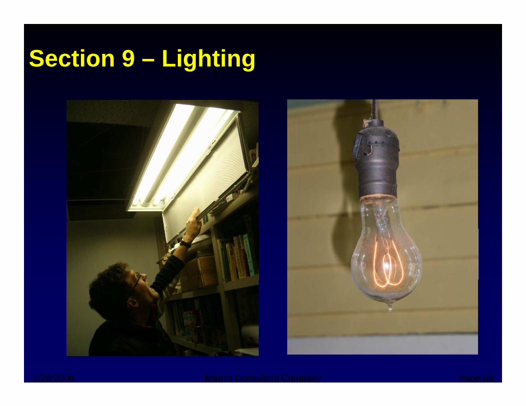
Section 9 – Lighting
1/28/2008 Mathis Consulting Company Page 69
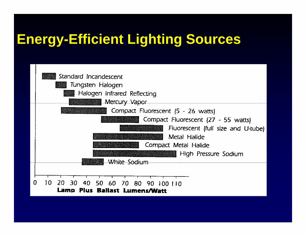
Energy-Efficient Lighting SourcesEnergy Efficient Lighting Sources
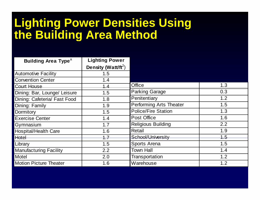
Lighting Power Densities Using the Building Area Methodthe Building Area Method
Building Area Typea Lighting Power Building Area Type g gDensity (Watt/ft2)
Automotive Facility 1.5Convention Center 1.4Court House 1 4 Office 1.3Court House 1.4Dining: Bar, Lounge/ Leisure 1.5Dining: Cafeteria/ Fast Food 1.8Dining: Family 1.9Dormitory 1 5
Parking Garage 0.3Penitentiary 1.2Performing Arts Theater 1.5Police/Fire Station 1.3Dormitory 1.5
Exercise Center 1.4Gymnasium 1.7Hospital/Health Care 1.6Hotel 1 7
Police/Fire Station 1.3Post Office 1.6Religious Building 2.2Retail 1.9School/University 1 5Hotel 1.7
Library 1.5Manufacturing Facility 2.2Motel 2.0Motion Picture Theater 1 6
School/University 1.5Sports Arena 1.5Town Hall 1.4Transportation 1.2Warehouse 1 2Motion Picture Theater 1.6 Warehouse 1.2
Does the Building Comply?
• Determine the total connected power in watts for the proposed lightingwatts for the proposed lighting
• Determine the interior lighting power budget for the entire building or spacebudget for the entire building or space
• Building complies if:I t i li hti b d t t t l t d– Interior lighting power budget - total connected power 0
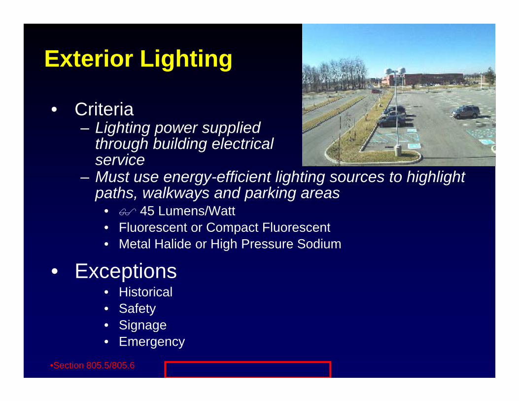
Exterior Lighting
• CriteriaLighting power supplied– Lighting power supplied through building electrical serviceMust use energy efficient lighting sources to highlight– Must use energy-efficient lighting sources to highlight paths, walkways and parking areas
• 45 Lumens/Watt• Fluorescent or Compact Fluorescent• Fluorescent or Compact Fluorescent• Metal Halide or High Pressure Sodium
• ExceptionsExceptions• Historical• Safety• SignageSignage• Emergency
•Section 805.5/805.6
Section 11Energy Cost Budget MethodEnergy Cost Budget Method
• Alternative to prescriptive method except buildings ith h i l twith no mechanical systems
• Based on overall building performanceexpressed as “energy cost budget”expressed as “energy cost budget”
• Mandatory Provisions all must be met• Budget (or baseline) based on prescriptive
measures• Allows trade-offs between measures• Useful for optimizing design
1/28/2008 Mathis Consulting Company Page 74
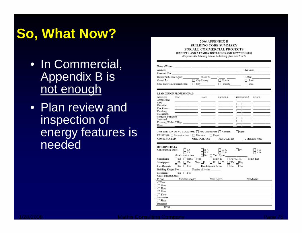
So, What Now?
• In Commercial, A di B iAppendix B is not enough
• Plan review and inspection of energy features isenergy features is needed
1/28/2008 Mathis Consulting Company Page 75
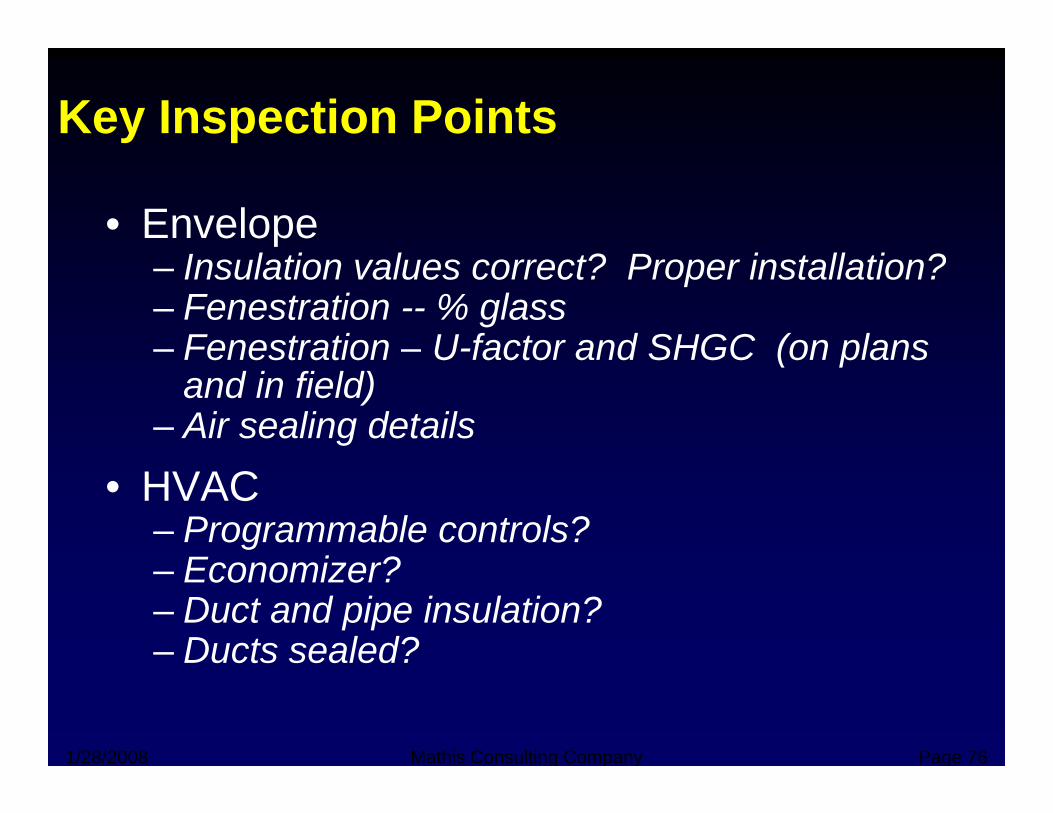
Key Inspection Points
• EnvelopeI l i l ? P i ll i ?– Insulation values correct? Proper installation?
– Fenestration -- % glass– Fenestration – U-factor and SHGC (on plansFenestration U factor and SHGC (on plans
and in field)– Air sealing details
• HVAC– Programmable controls?
E i ?– Economizer?– Duct and pipe insulation?– Ducts sealed?ucts sea ed
1/28/2008 Mathis Consulting Company Page 76

Key Inspection Points (cont.)• HVAC (continued)
– No simultaneous heating and cooling (except where allowed for reheat)allowed for reheat)
– Complex systems• Fan power• Temperature reset• Temperature reset• Zoning• Reheat limitation• Etc• Etc.
• Lighting– If most lamps are not T-8 fluorescent or more efficient p
lamps, need to check– Check controls– Exit signs– Exterior lighting
1/28/2008 Mathis Consulting Company Page 77
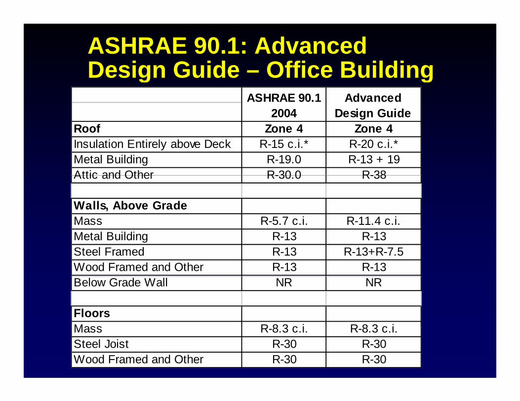
ASHRAE 90.1: Advanced Design Guide – Office BuildingDesign Guide Office Building
R f Z 4 Z 4
Advanced Design Guide
ASHRAE 90.1 2004
Roof Zone 4 Zone 4Insulation Entirely above Deck R-15 c.i.* R-20 c.i.*Metal Building R-19.0 R-13 + 19Attic and Other R-30 0 R-38Attic and Other R-30.0 R-38
Walls, Above GradeMass R-5.7 c.i. R-11.4 c.i.Metal Building R-13 R-13Steel Framed R-13 R-13+R-7.5Wood Framed and Other R-13 R-13Below Grade Wall NR NR
FloorsMass R 8 3 c i R 8 3 c iMass R-8.3 c.i. R-8.3 c.i.Steel Joist R-30 R-30Wood Framed and Other R-30 R-30
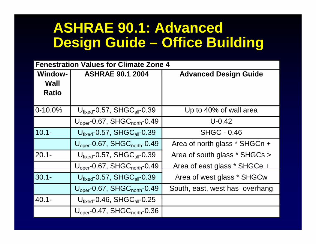
ASHRAE 90.1: Advanced Design Guide – Office BuildingDesign Guide Office Building
Fenestration Values for Climate Zone 4Window- ASHRAE 90.1 2004 Advanced Design GuideWindow
Wall Ratio
ASHRAE 90.1 2004 Advanced Design Guide
0-10.0% Ufixed-0.57, SHGCall-0.39 Up to 40% of wall areaUoper-0.67, SHGCnorth-0.49 U-0.42
10.1- Ufixed-0.57, SHGCall-0.39 SHGC - 0.46Uoper-0.67, SHGCnorth-0.49 Area of north glass * SHGCn +
20.1- Ufixed-0.57, SHGCall-0.39 Area of south glass * SHGCs >Uoper-0.67, SHGCnorth-0.49 Area of east glass * SHGCe +Uoper 0.67, SHGCnorth 0.49 Area of east glass SHGCe
30.1- Ufixed-0.57, SHGCall-0.39 Area of west glass * SHGCwUoper-0.67, SHGCnorth-0.49 South, east, west has overhang
40 1 U 0 46 SHGC 0 2540.1- Ufixed-0.46, SHGCall-0.25Uoper-0.47, SHGCnorth-0.36
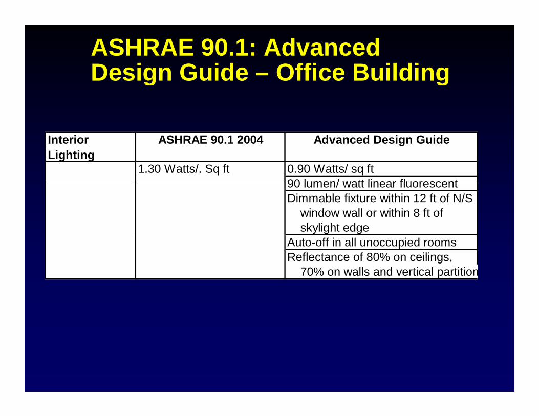
ASHRAE 90.1: Advanced Design Guide – Office BuildingDesign Guide Office Building
1.30 Watts/. Sq ft 0.90 Watts/ sq ft90 lumen/ watt linear fluorescent
ASHRAE 90.1 2004 Advanced Design GuideInterior Lighting
90 lumen/ watt linear fluorescentDimmable fixture within 12 ft of N/S window wall or within 8 ft of skylight edgeAuto-off in all unoccupied roomsReflectance of 80% on ceilings, 70% on walls and vertical partition
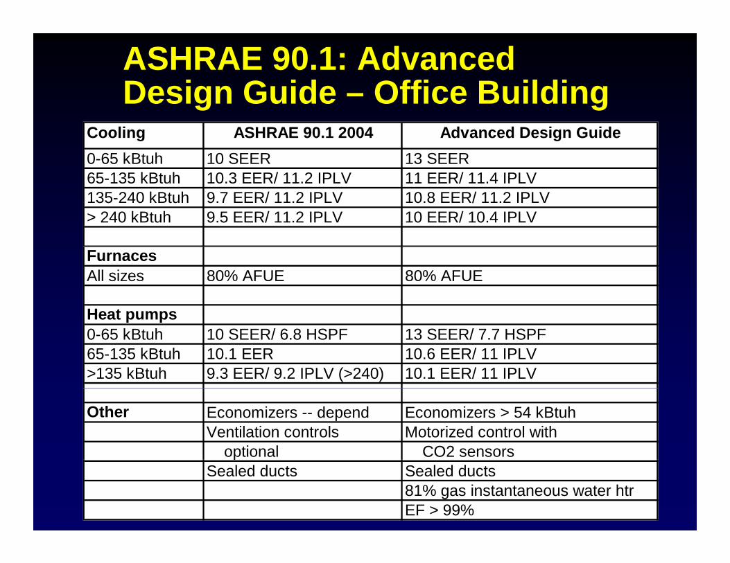
ASHRAE 90.1: Advanced Design Guide – Office Buildingg g
0-65 kBtuh 10 SEER 13 SEER65 135 kBt h 10 3 EER/ 11 2 IPLV 11 EER/ 11 4 IPLV
ASHRAE 90.1 2004 Advanced Design GuideCooling
65-135 kBtuh 10.3 EER/ 11.2 IPLV 11 EER/ 11.4 IPLV135-240 kBtuh 9.7 EER/ 11.2 IPLV 10.8 EER/ 11.2 IPLV> 240 kBtuh 9.5 EER/ 11.2 IPLV 10 EER/ 10.4 IPLV
FurnacesAll sizes 80% AFUE 80% AFUE
Heat pumpsHeat pumps0-65 kBtuh 10 SEER/ 6.8 HSPF 13 SEER/ 7.7 HSPF65-135 kBtuh 10.1 EER 10.6 EER/ 11 IPLV>135 kBtuh 9.3 EER/ 9.2 IPLV (>240) 10.1 EER/ 11 IPLV
Other Economizers -- depend Economizers > 54 kBtuhVentilation controls Motorized control with optional CO2 sensorspSealed ducts Sealed ducts
81% gas instantaneous water htrEF > 99%

ASHRAE 90.1: Advanced Design Guide – Office BuildingDesign Guide Office Building
R f Z 4 Z 4
Advanced Design Guide
ASHRAE 90.1 2004
Roof Zone 4 Zone 4Insulation Entirely above Deck R-15 c.i.* R-20 c.i.*Metal Building R-19.0 R-13 + 19Attic and Other R-30 0 R-38Attic and Other R-30.0 R-38
Walls, Above GradeMass R-5.7 c.i. R-11.4 c.i.Metal Building R-13 R-13Steel Framed R-13 R-13+R-7.5Wood Framed and Other R-13 R-13Below Grade Wall NR NR
FloorsMass R 8 3 c i R 8 3 c iMass R-8.3 c.i. R-8.3 c.i.Steel Joist R-30 R-30Wood Framed and Other R-30 R-30


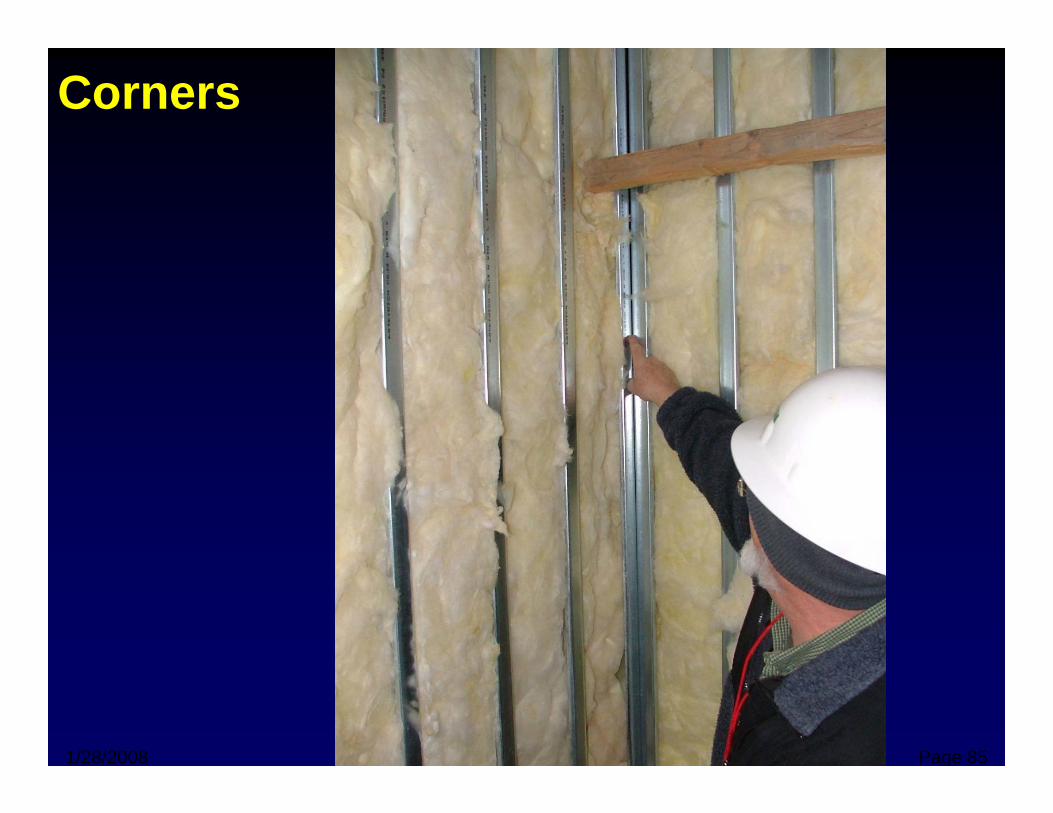
Corners
1/28/2008 Mathis Consulting Company Page 85
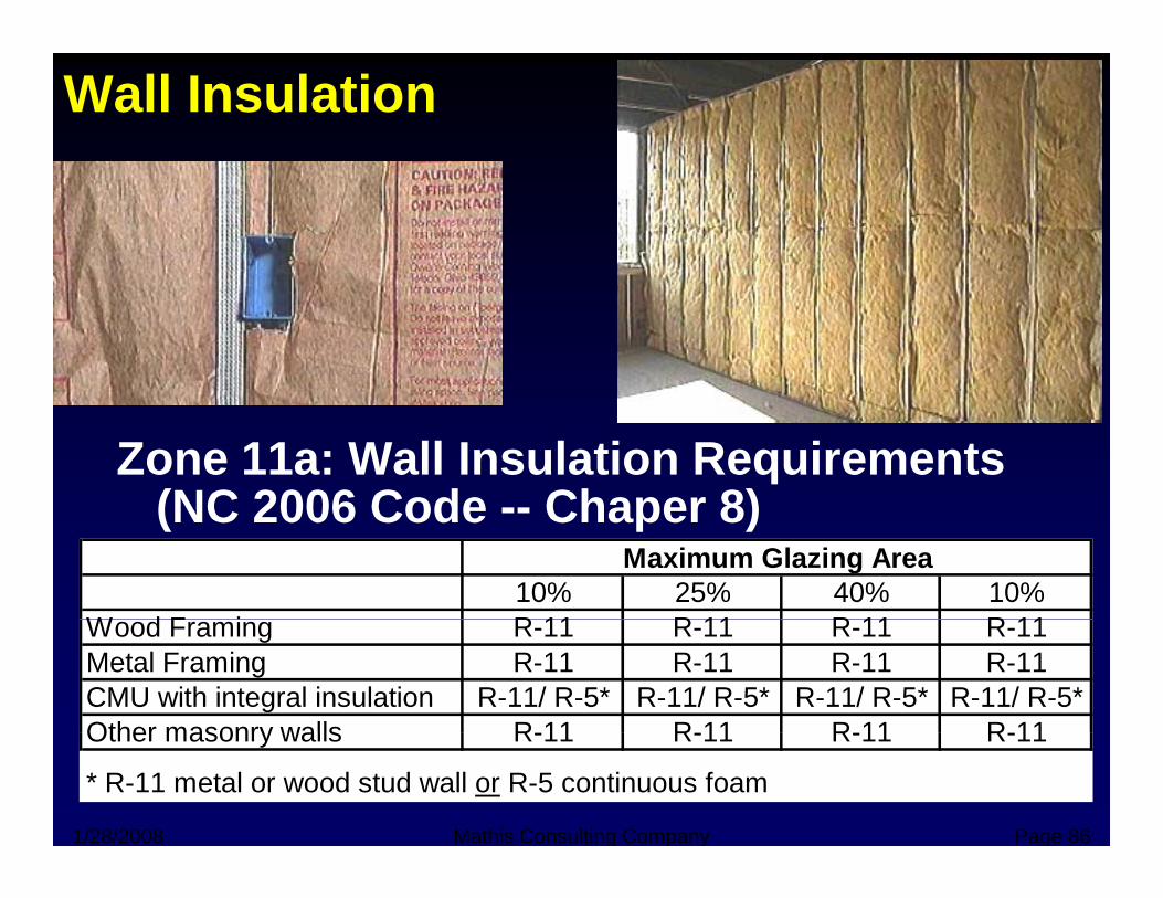
Wall Insulation
Zone 11a: Wall Insulation Requirements(NC 2006 Code Chaper 8)(NC 2006 Code -- Chaper 8)
10% 25% 40% 10%W d F i R 11 R 11 R 11 R 11
Maximum Glazing Area
Wood Framing R-11 R-11 R-11 R-11Metal Framing R-11 R-11 R-11 R-11CMU with integral insulation R-11/ R-5* R-11/ R-5* R-11/ R-5* R-11/ R-5*Other masonry walls R 11 R 11 R 11 R 11
1/28/2008 Mathis Consulting Company Page 86
Other masonry walls R-11 R-11 R-11 R-11
* R-11 metal or wood stud wall or R-5 continuous foam
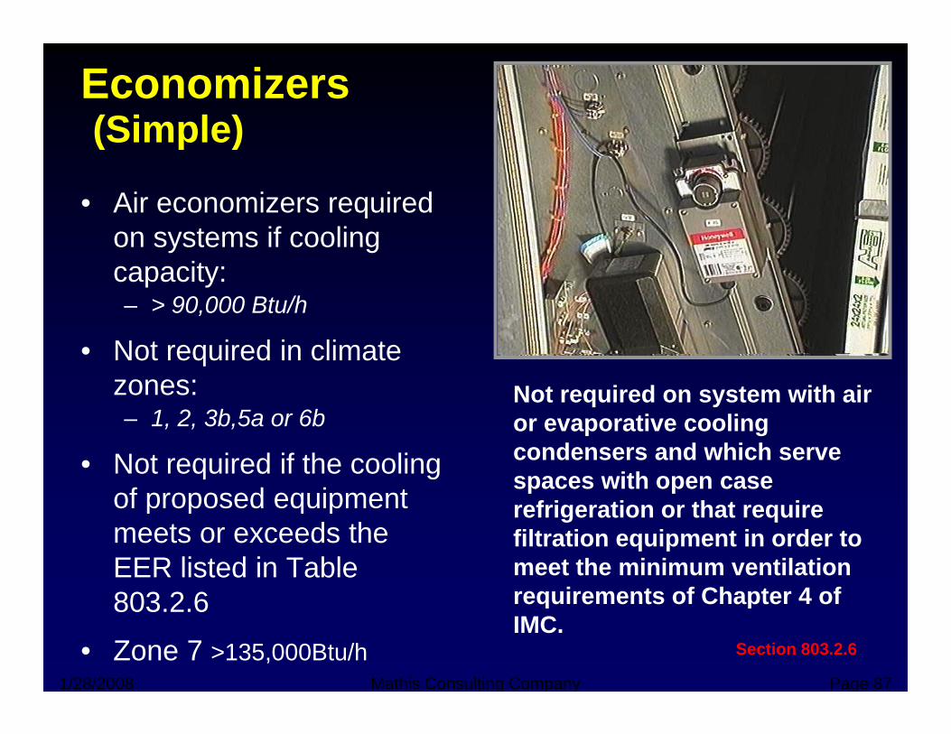
Economizers(Simple)(Simple)
• Air economizers required t if lion systems if cooling
capacity:– > 90,000 Btu/h
• Not required in climate zones:
1 2 3b 5a or 6bNot required on system with air
– 1, 2, 3b,5a or 6b
• Not required if the cooling of proposed equipment
or evaporative cooling condensers and which serve spaces with open case refrigeration or that requireof proposed equipment
meets or exceeds the EER listed in Table 803 2 6
refrigeration or that require filtration equipment in order to meet the minimum ventilation requirements of Chapter 4 of
1/28/2008 Mathis Consulting Company Page 87
803.2.6
• Zone 7 >135,000Btu/h Section 803.2.6
requirements of Chapter 4 of IMC.
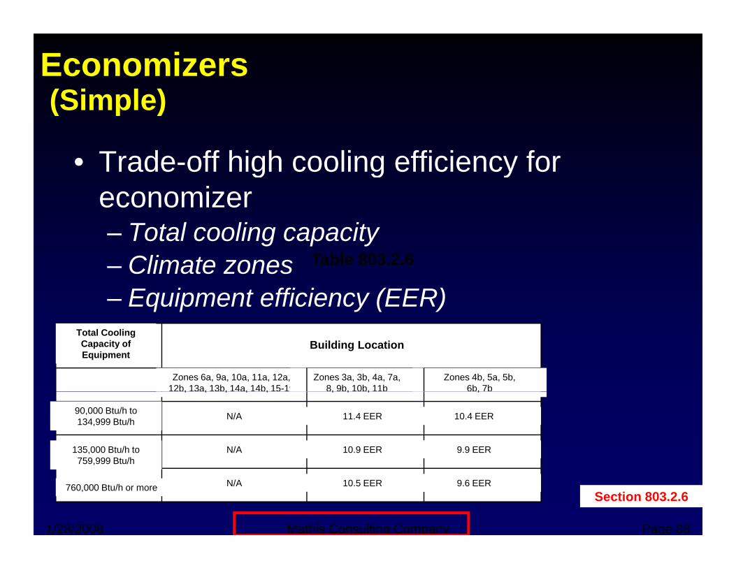
Economizers(Simple)(Simple)
• Trade-off high cooling efficiency for g g yeconomizer– Total cooling capacity– Climate zones– Equipment efficiency (EER)
Table 803.2.6
Total Cooling Capacity of Equipment
Building Location
Zones 6a, 9a, 10a, 11a, 12a, 12b, 13a, 13b, 14a, 14b, 15-19
Zones 3a, 3b, 4a, 7a, 8, 9b, 10b, 11b
Zones 4b, 5a, 5b, 6b, 7b, , , , , , , , ,
N/A 11.4 EER
N/A 10.9 EER
10.4 EER
9.9 EER
90,000 Btu/h to 134,999 Btu/h
135,000 Btu/h to 759,999 Btu/h
1/28/2008 Mathis Consulting Company Page 88
N/A 10.5 EER 9.6 EER
759,999 Btu/h
760,000 Btu/h or moreSection 803.2.6
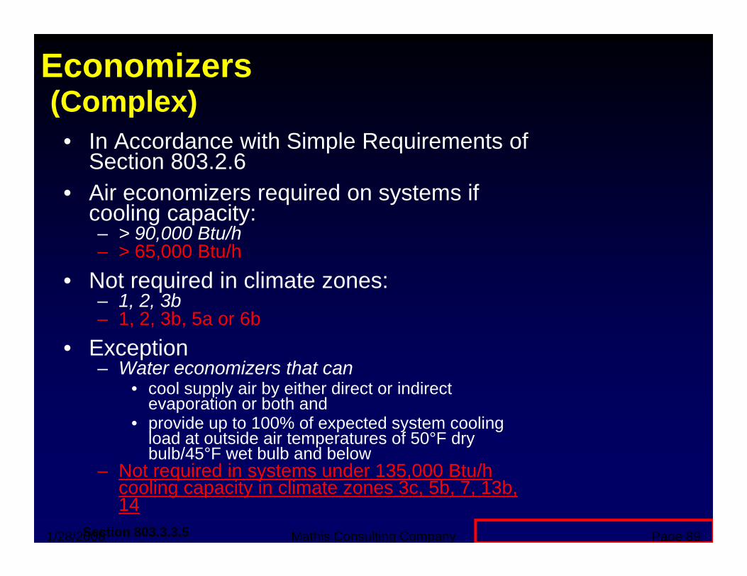
Economizers(Complex)(Complex)
• In Accordance with Simple Requirements of Section 803.2.6
• Air economizers required on systems if cooling capacity:– > 90,000 Btu/h
> 65 000 Btu/h– > 65,000 Btu/h • Not required in climate zones:
– 1, 2, 3b – 1, 2, 3b, 5a or 6b1, 2, 3b, 5a or 6b
• Exception– Water economizers that can
• cool supply air by either direct or indirect pp y yevaporation or both and
• provide up to 100% of expected system cooling load at outside air temperatures of 50°F dry bulb/45°F wet bulb and below
Not required in systems under 135 000 Btu/h
1/28/2008 Mathis Consulting Company Page 89
– Not required in systems under 135,000 Btu/h cooling capacity in climate zones 3c, 5b, 7, 13b, 14
Section 803.3.3.5
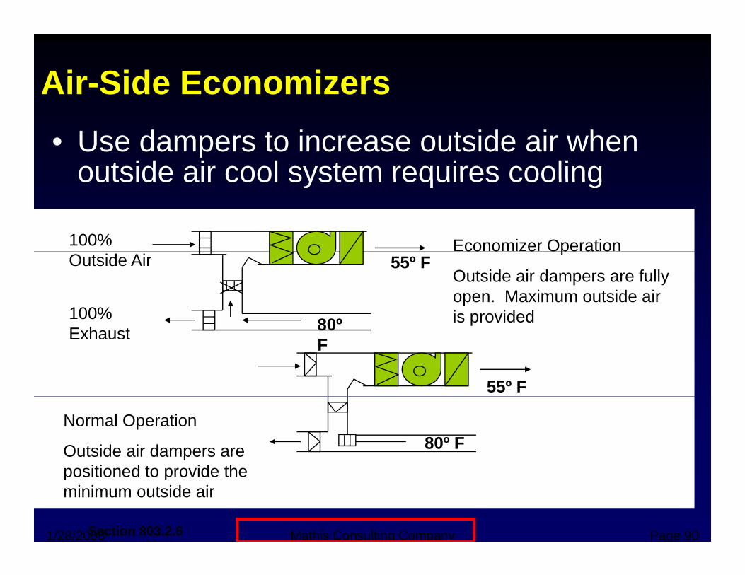
Air-Side Economizers• Use dampers to increase outside air when
outside air cool system requires coolingoutside air cool system requires cooling
100% Economizer OperationOutside Air 55º F
80º100%
co o e Ope a o
Outside air dampers are fully open. Maximum outside air is provided80º
FExhaustp
55º F
80º FNormal Operation
Outside air dampers are positioned to provide the
1/28/2008 Mathis Consulting Company Page 90
positioned to provide the minimum outside air
Section 803.2.6
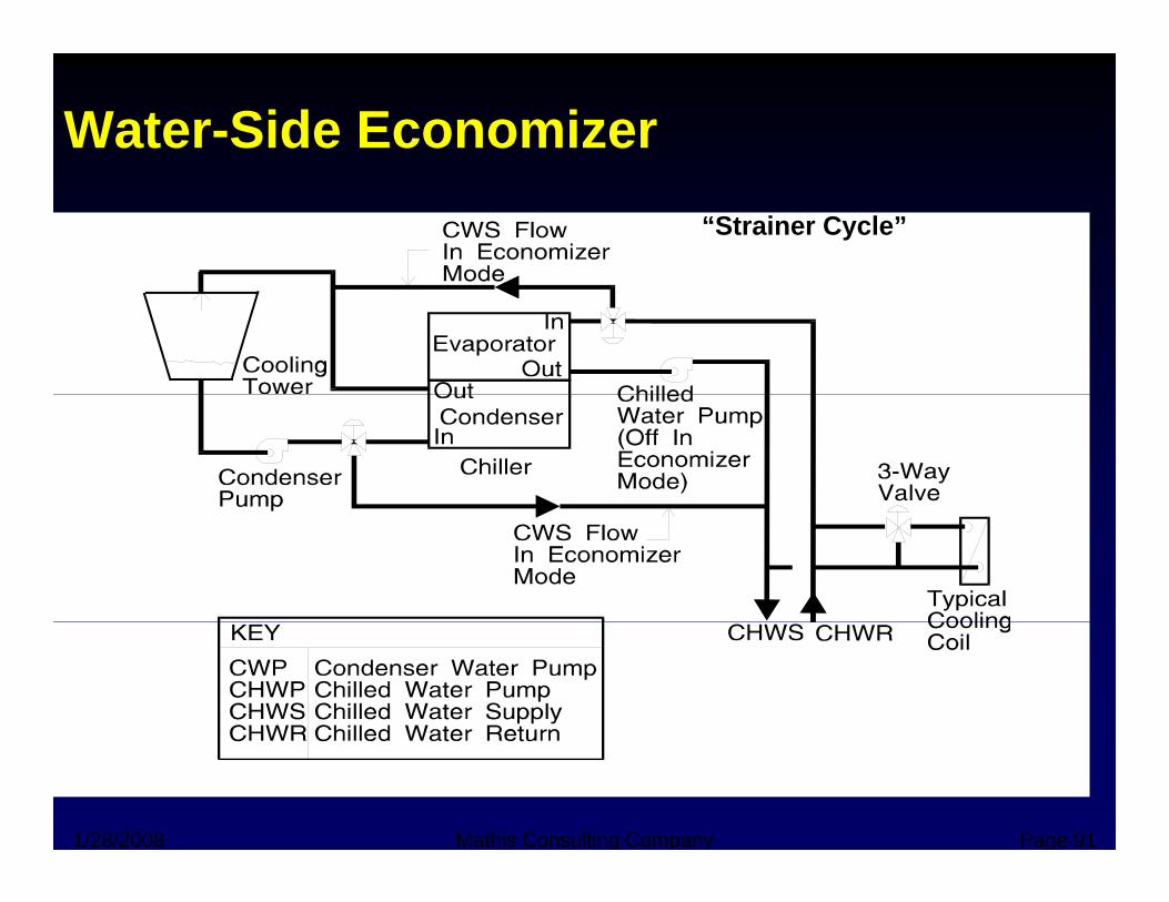
Water-Side Economizer“Strainer Cycle”
1/28/2008 Mathis Consulting Company Page 91
Shutoff Dampers(Simple and Complex)(Simple and Complex)
• Required for outdoor-air and exhaust t ith d i i fl t 3000systems with design air flow rates > 3000
cfm• Must automatically close during periods of
non-use• Simple: Exceptions
– Where restricted by health and life safety codesWhere serving areas designed for continuous– Where serving areas designed for continuous operation
– Systems with readily accessible manual
1/28/2008 Mathis Consulting Company Page 92
y ydampers
Section 803.2.7/803.3.3.4
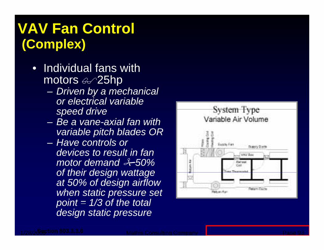
VAV Fan Control(Complex)(Complex)
• Individual fans with motors 25hpmotors 25hp– Driven by a mechanical
or electrical variable d d ispeed drive
– Be a vane-axial fan with variable pitch blades ORHave controls or– Have controls or devices to result in fan motor demand 50% of their design wattageof their design wattage at 50% of design airflow when static pressure set point = 1/3 of the total
1/28/2008 Mathis Consulting Company Page 93
point 1/3 of the total design static pressure
Section 803.3.3.6
Heat Rejection Equipment(Complex) New 2004 Requirement(Complex)
• Each fan powered by a motor 7.5 hp to
New 2004 Requirement
– have capability to operate that fan at 2/3 of full speed or lessHave controls to automatically change the fan– Have controls to automatically change the fan speed to control the leaving fluid temperature or condensing temperature/pressure of the heat rejection device
• Exception p– Factory-installed heat rejection devices within
HVAC equipment tested and rated in accordance with Tables 803 3 2(1) through 803 3 2(3)
1/28/2008 Mathis Consulting Company Page 94
with Tables 803.3.2(1) through 803.3.2(3)
Section 803.3.3.8
Requirements for Multiple Zone Systems(Complex)
• Systems shall be VAV systems that are d i d d bl f b i t ll d tdesigned and capable of being controlled to reduce primary air supply to each zone to a minimum before reheating recooling orminimum before reheating, recooling or mixing takes place
• Several exceptions• Several exceptions
1/28/2008 Mathis Consulting Company Page 95Section 803.3.4
Duct and Plenum Insulation(Simple and Complex)(Simple and Complex)• Required for supply and return ducts and plenums
L t d i diti d R5– Located in unconditioned space - R5– Located outside the building envelope - R8
• Exceptionsp– Located within equipment– Design temperature difference between interior and
exterior of duct or plenum > 15°FD t d i d t t t t ti 3• Ducts designed to operate at static pressures > 3 in. wg to be leak tested in accordance with SMACNA
• Complex: Furnish documentation that representative sections totaling at least 25% of the duct area have been tested and meet the
i
1/28/2008 Mathis Consulting Company Page 96
requirementsSection 803.2.8/803.3.6
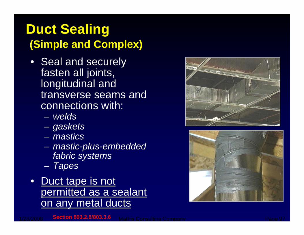
Duct Sealing(Simple and Complex)(Simple and Complex)• Seal and securely
fasten all jointsfasten all joints, longitudinal and transverse seams and
ti ithconnections with:– welds– gaskets– mastics– mastic-plus-embedded
fabric systems– Tapes
• Duct tape is not permitted as a sealant
1/28/2008 Mathis Consulting Company Page 97
permitted as a sealant on any metal ducts
Section 803.2.8/803.3.6
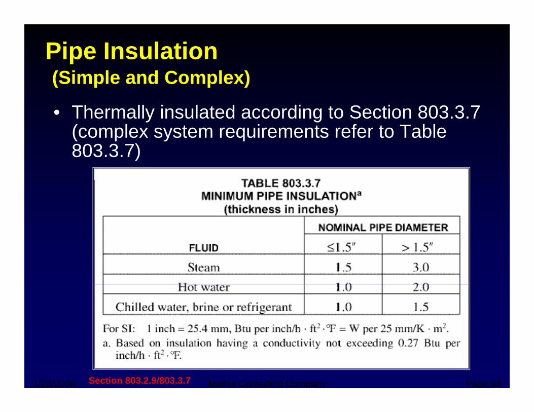
Pipe Insulation(Simple and Complex)(Simple and Complex)
• Thermally insulated according to Section 803.3.7 (complex system requirements refer to Table(complex system requirements refer to Table 803.3.7)
1/28/2008 Mathis Consulting Company Page 98Section 803.2.9/803.3.7
Pipe Insulation Exceptions
• Exceptionsp– Factory-installed piping within equipment– Piping conveying fluids between 55°F and
105°F– Piping conveying fluids not heated or
l d th h th f f il f lcooled through the use of fossil fuels or electric power
– Runout piping not exceeding 4 ft in length– Runout piping not exceeding 4 ft in length and 1 in. in diameter between the control valve and HVAC coil
1/28/2008 Mathis Consulting Company Page 99Section 803.2.9/803.3.7
HVAC System Completion (Complex)
• Before issuance of tifi t fcertificate of occupancy
– Air system balancing– Hydronic system y y
balancing– Manuals
1/28/2008 Mathis Consulting Company Page 100Section 803.3.8
System Balancing(Complex)(Complex)
• Supply Air Outlets and Zone Terminal D iDevices– Must Have Means to Air Balance– Discharge Dampers Prohibited on ConstantDischarge Dampers Prohibited on Constant
Volume and Variable Volume Fans with Motors > 25 Hp
• Hydronic Systems– Individual Hydronic Heating and Cooling Coils to
b E i d ith M f B l i dbe Equipped with Means for Balancing and Pressure Test Connections
1/28/2008 Mathis Consulting Company Page 101
Section 803.3.8.1
ManualsManuals(Complex)
• O & M Manual RequiredO & M Manual Required– Contents
• Equipment Capacity and Required Maintenance E i O & M M l• Equipment O & M Manuals
• HVAC System Control Maintenance and Calibration Information
• Written Narrative of Each System Operation
1/28/2008 Mathis Consulting Company Page 102Section 803.3.8.3
Heat Recovery for SWHy
• Condenser heat recovery required for h ti / h ti f SWH id dheating/reheating of SWH provided:– Facility operates 24 hours/day– Total installed heat capacity of water-cooledTotal installed heat capacity of water cooled
systems >6,000,000 Btu/hr of heat rejection– Design SWH load >1,000,000 Btu/h
• The required heat recovery system shall have the capacity to provide the smaller of :– 60% of the peak heat rejection load at design
conditions or– the preheating required to raise the peak service
1/28/2008 Mathis Consulting Company Page 103
the preheating required to raise the peak service hot water draw to 85 degree F
Section 803.3.9
Service Water HeatingService Water Heating
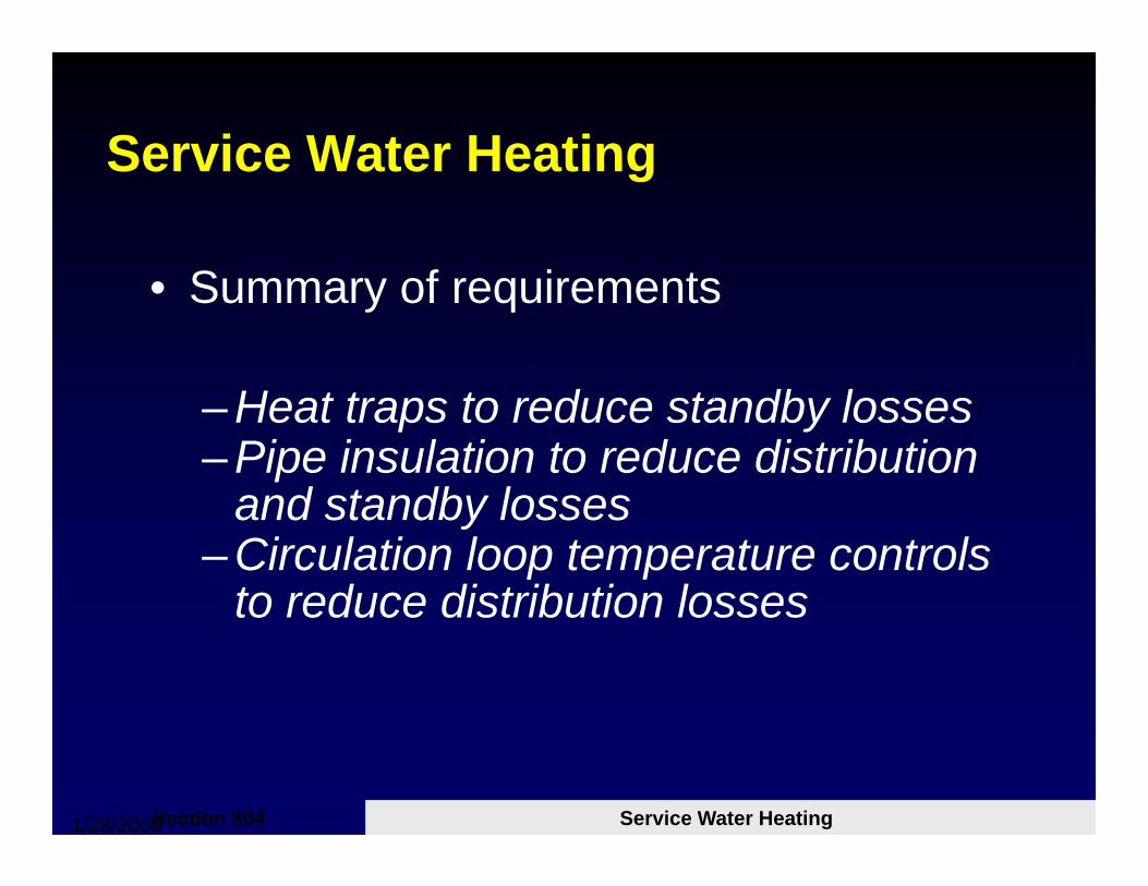
S f i t• Summary of requirements
– Heat traps to reduce standby losses– Pipe insulation to reduce distribution
and standby lossesand standby losses– Circulation loop temperature controls
to reduce distribution lossesto reduce distribution losses
1/28/2008 Mathis Consulting Company Page 104Service Water HeatingSection 804
Typical Commercial Building Energy yp g gyConsumption Patterns
Equip.OtherMisc
Cooking
Refrgd'n
Lighting
HVACWater Htg
1/28/2008 Mathis Consulting Company Page 105
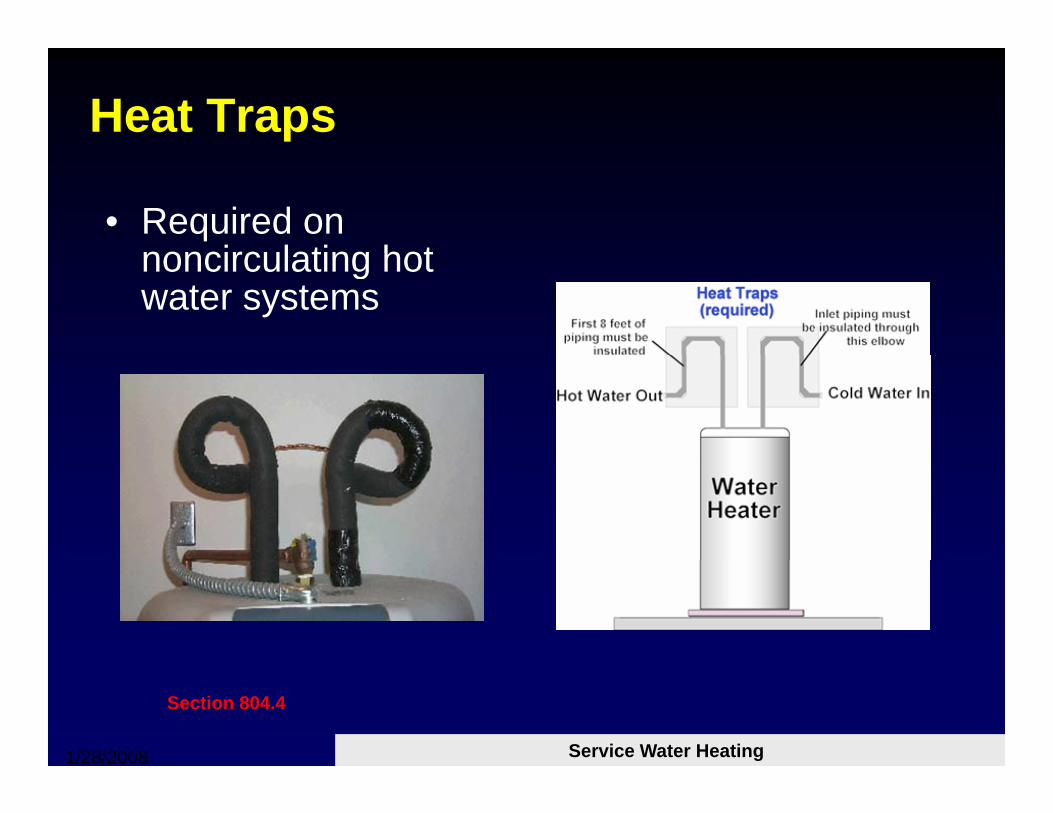
Heat Traps
• Required on noncirculating hotnoncirculating hot water systems
1/28/2008 Mathis Consulting Company Page 106Service Water Heating
Section 804.4
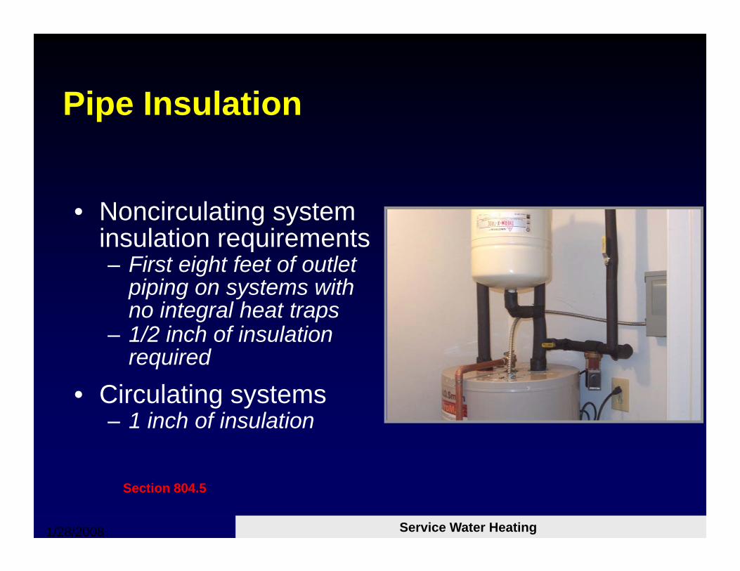
Pipe InsulationPipe Insulation
• Noncirculating system insulation requirementsq– First eight feet of outlet
piping on systems with no integral heat trapsg p
– 1/2 inch of insulation required
• Circulating systems• Circulating systems– 1 inch of insulation
1/28/2008 Mathis Consulting Company Page 107Service Water Heating
Section 804.5
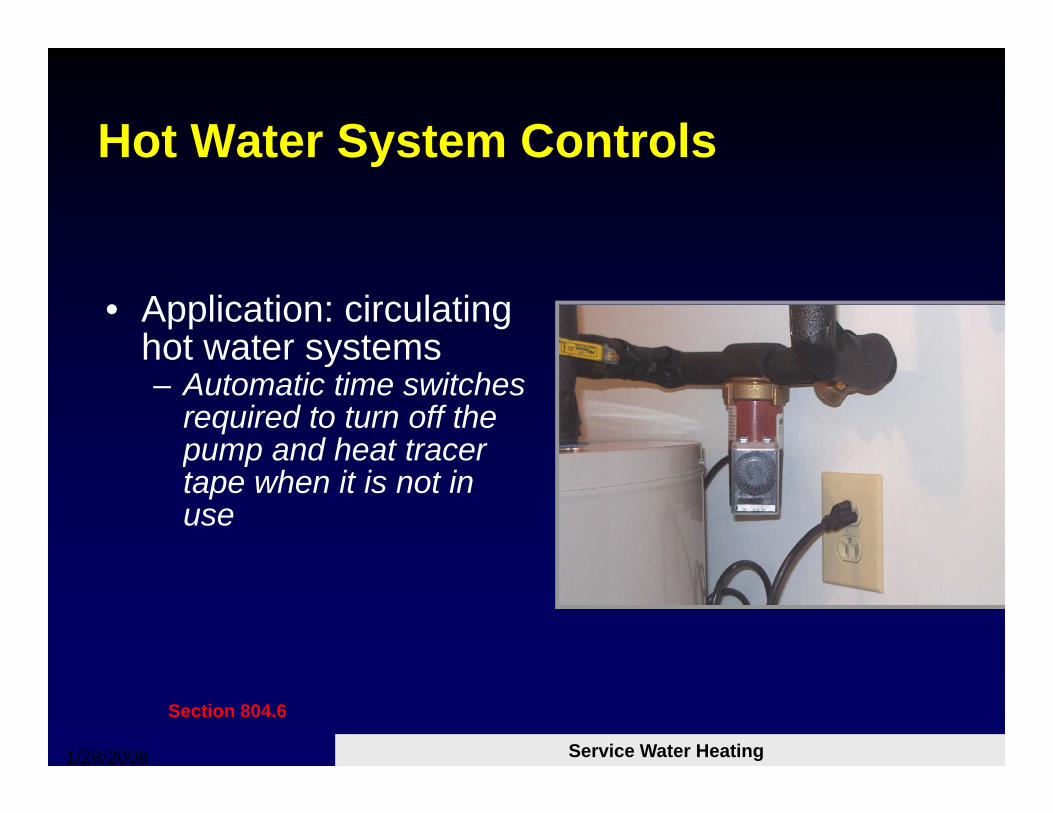
Hot Water System ControlsHot Water System Controls
• Application: circulating hot water systemshot water systems– Automatic time switches
required to turn off the pump and heat tracerpump and heat tracer tape when it is not in use
1/28/2008 Mathis Consulting Company Page 108Service Water Heating
Section 804.6
More Information
• For additional training materials see www.energycodes.gov/training/presentation
s.stm
• Code Books:www.iccsafe.org
1/28/2008 Mathis Consulting Company Page 109
Commercial Energy Code ComplianceLighting RequirementsLighting Requirements
Chapter 8 NCECC
1/28/2008 Mathis Consulting Company Page 110
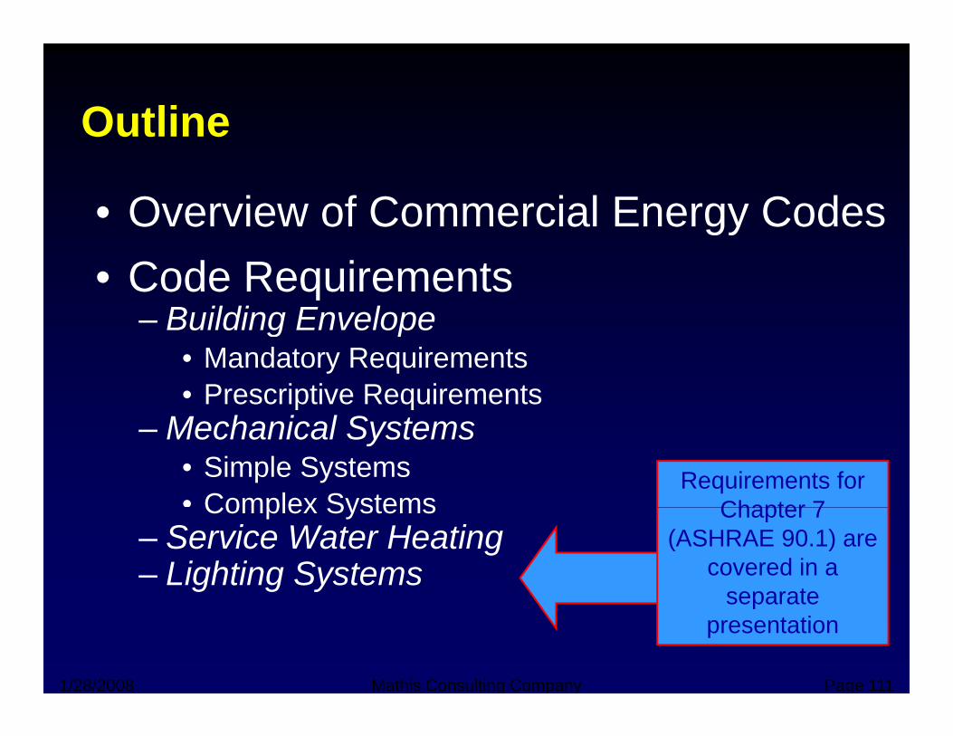
OutlineOutline
• Overview of Commercial Energy Codesgy• Code Requirements
– Building Envelope– Building Envelope• Mandatory Requirements• Prescriptive Requirements
– Mechanical Systems• Simple Systems• Complex Systems
Requirements for Chapter 7Complex Systems
– Service Water Heating– Lighting Systems
Chapter 7 (ASHRAE 90.1) are
covered in a separate
1/28/2008 Mathis Consulting Company Page 111
separate presentation
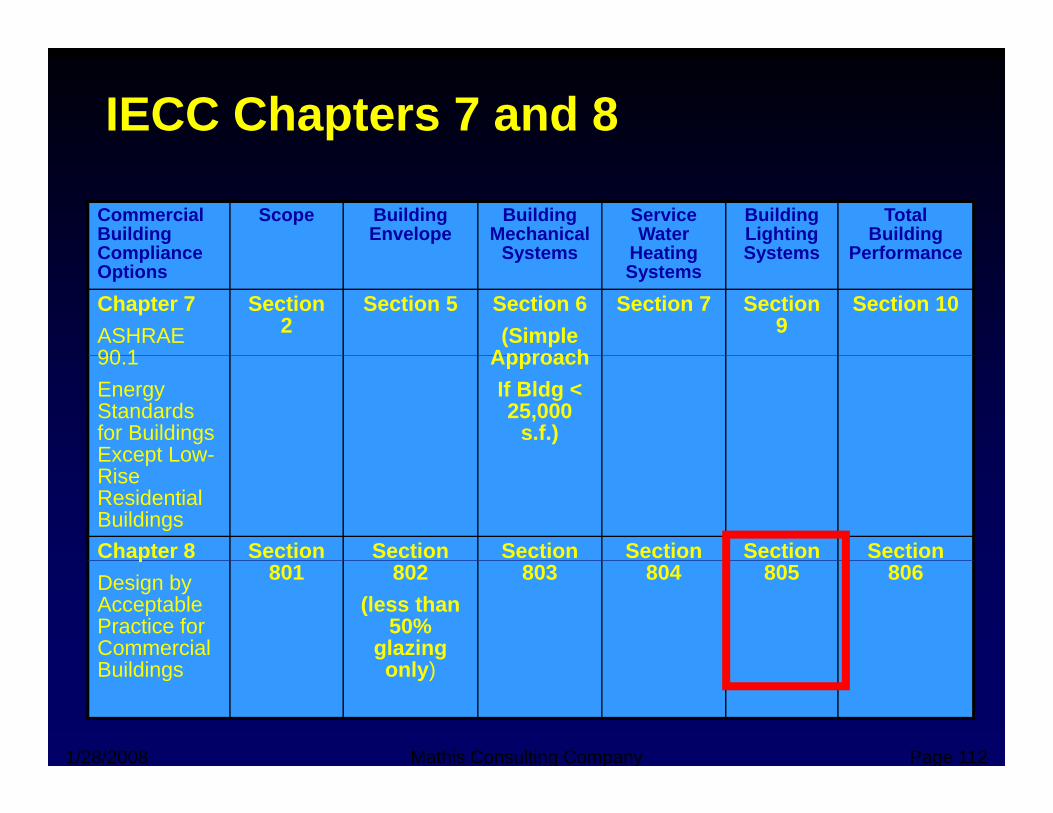
IECC Chapters 7 and 8
Commercial Building Compliance
Scope Building Envelope
Building Mechanical
Systems
Service Water
Heating
Building Lighting Systems
Total Building
PerformanceCompliance Options
Systems Heating Systems
Systems Performance
Chapter 7ASHRAE 90 1
Section 2
Section 5 Section 6(Simple
Approach
Section 7 Section 9
Section 10
90.1Energy Standards for Buildings Except Low-
ApproachIf Bldg < 25,000
s.f.)Except LowRise Residential BuildingsChapter 8 Section Section Section Section Section Section pDesign by Acceptable Practice for Commercial B ildi
801 802(less than
50% glazing
l )
803 804 805 806
1/28/2008 Mathis Consulting Company Page 112
Buildings only)
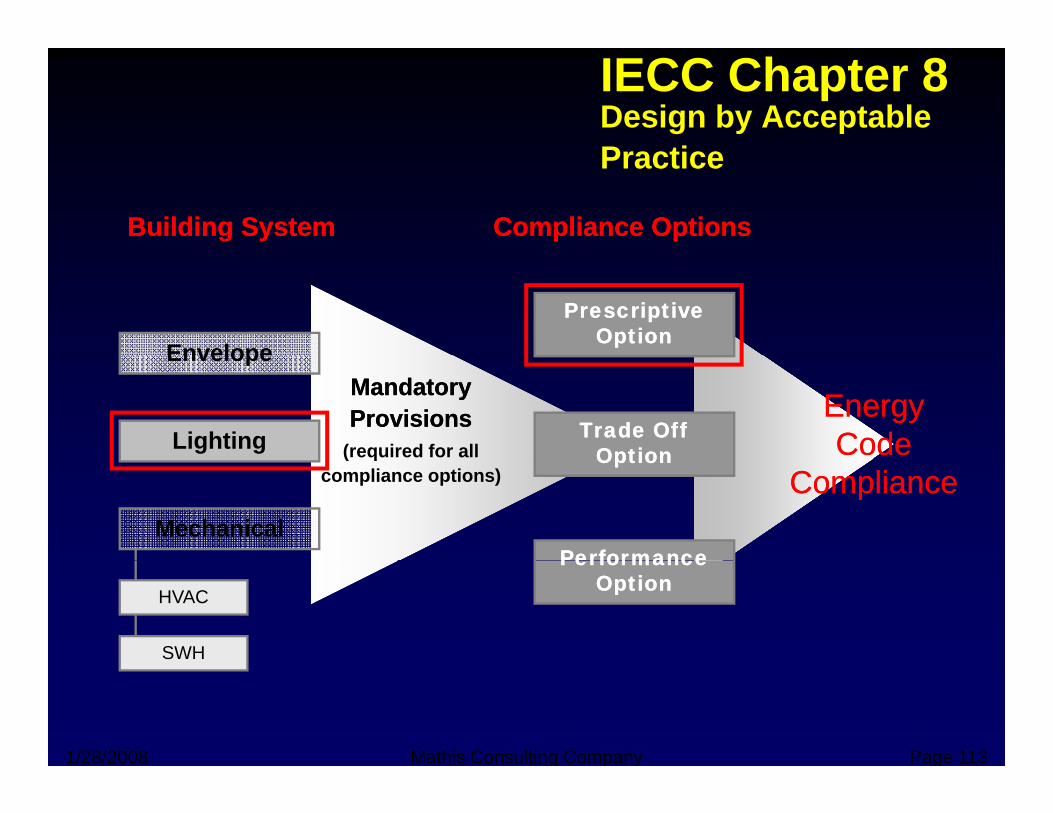
IECC Chapter 8Design by Acceptable P tiPractice
Building SystemBuilding System Compliance OptionsCompliance Options
Envelope
Prescriptive Prescriptive OptionOption
Mandatory Mandatory ProvisionsProvisions
(required for all
Envelope
LightingEnergy Energy Code Code Trade Off Trade Off
OptionOption( qcompliance options)
Mechanical
ComplianceComplianceOptionOption
Performance Performance
HVAC
SWH
Performance Performance OptionOption
1/28/2008 Mathis Consulting Company Page 113
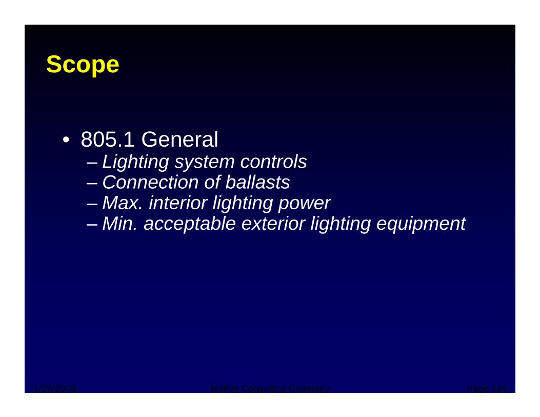
Scope p
• 805.1 General– Lighting system controls
Connection of ballasts– Connection of ballasts– Max. interior lighting power– Min. acceptable exterior lighting equipment
1/28/2008 Mathis Consulting Company Page 114
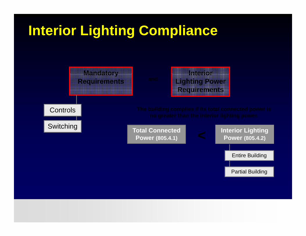
Interior Lighting Compliance
Mandatory InteriorMandatory Requirements
Interior Lighting Power Requirements
and
Controls
Switching Total Connected Interior Lighting <
The building complies if its total connected power is no greater than the interior lighting power.
Entire Building
Power (805.4.1)g g
Power (805.4.2)<
Partial Building
1/28/2008 Mathis Consulting Company Page 115
Interior Lighting Controls
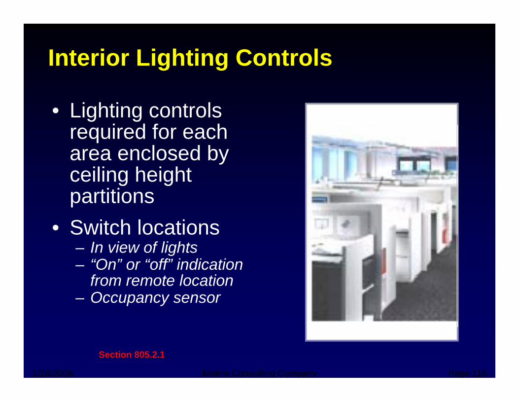
• Lighting controls i d f hrequired for each
area enclosed by ceiling heightceiling height partitions
• Switch locations• Switch locations– In view of lights– “On” or “off” indication
f t l tifrom remote location– Occupancy sensor
1/28/2008 Mathis Consulting Company Page 116
Section 805.2.1
Interior Lighting Controls
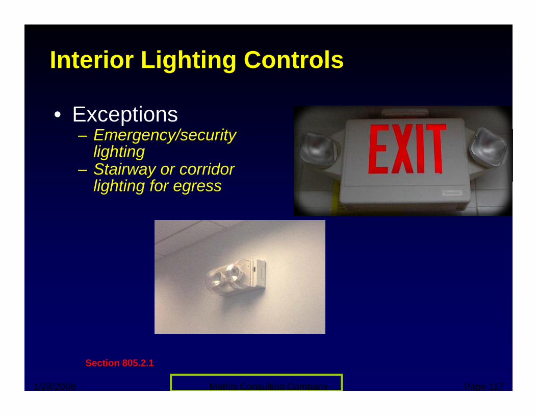
• ExceptionsE / it– Emergency/security lighting
– Stairway or corridor li hti flighting for egress
1/28/2008 Mathis Consulting Company Page 117
Section 805.2.1
Additional Controls
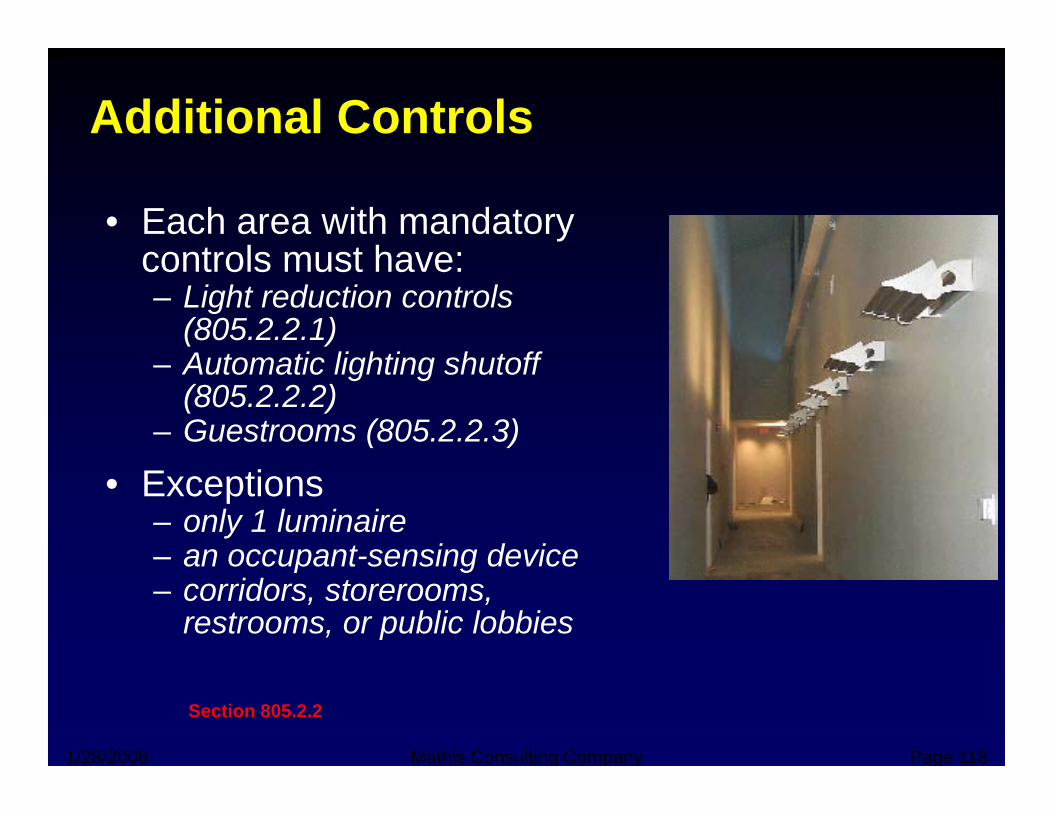
• Each area with mandatory controls must have:controls must have:– Light reduction controls
(805.2.2.1)A t ti li hti h t ff– Automatic lighting shutoff (805.2.2.2)
– Guestrooms (805.2.2.3)
• Exceptions– only 1 luminaire– an occupant-sensing devicean occupant sensing device– corridors, storerooms,
restrooms, or public lobbies
1/28/2008 Mathis Consulting Company Page 118
Section 805.2.2
Bi-Level SwitchingLi ht R d ti C t lLight Reduction Controls
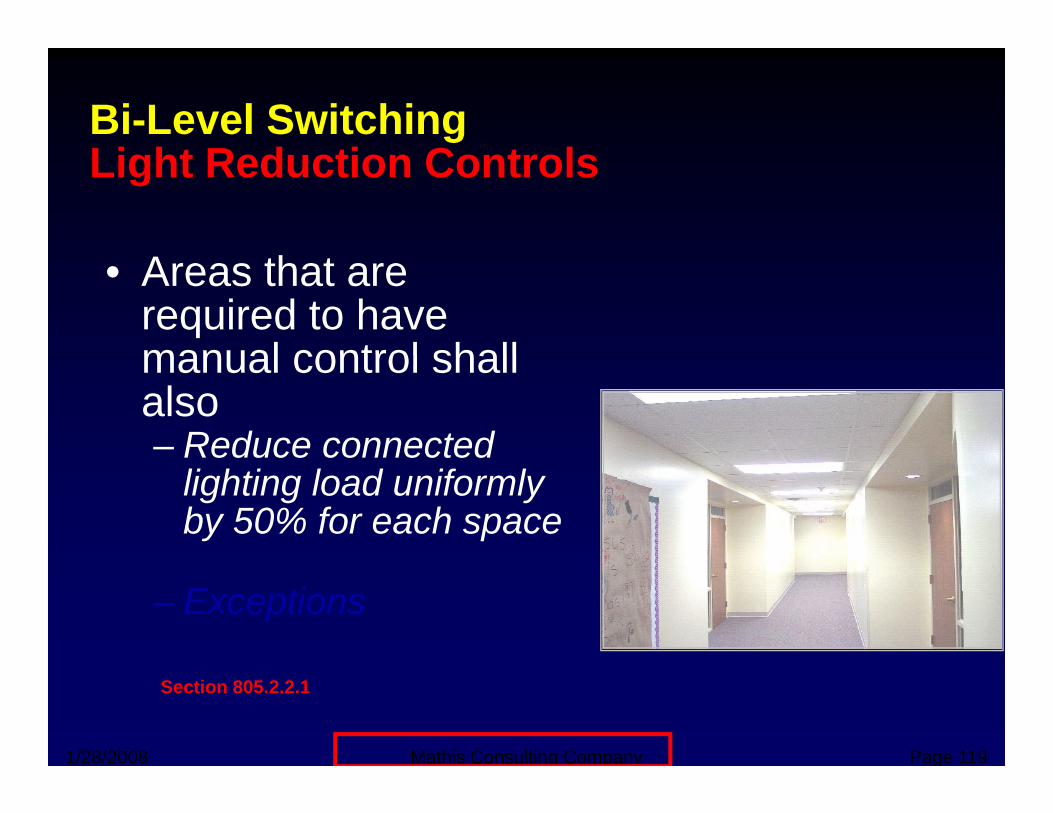
• Areas that are required to have manual control shallmanual control shall also– Reduce connected
lighting load uniformly by 50% for each space
– Exceptions
1/28/2008 Mathis Consulting Company Page 119
Section 805.2.2.1
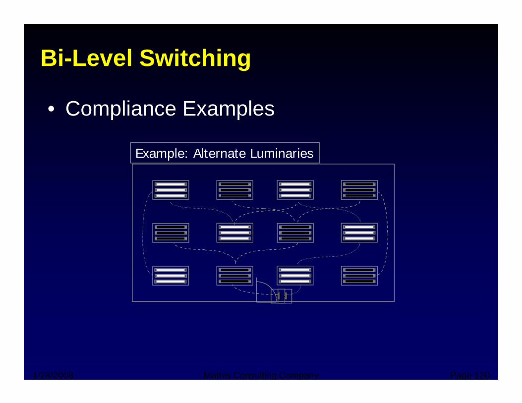
Bi-Level Switching
• Compliance Examples
Example: Alternate Luminaries
S S
1/28/2008 Mathis Consulting Company Page 120
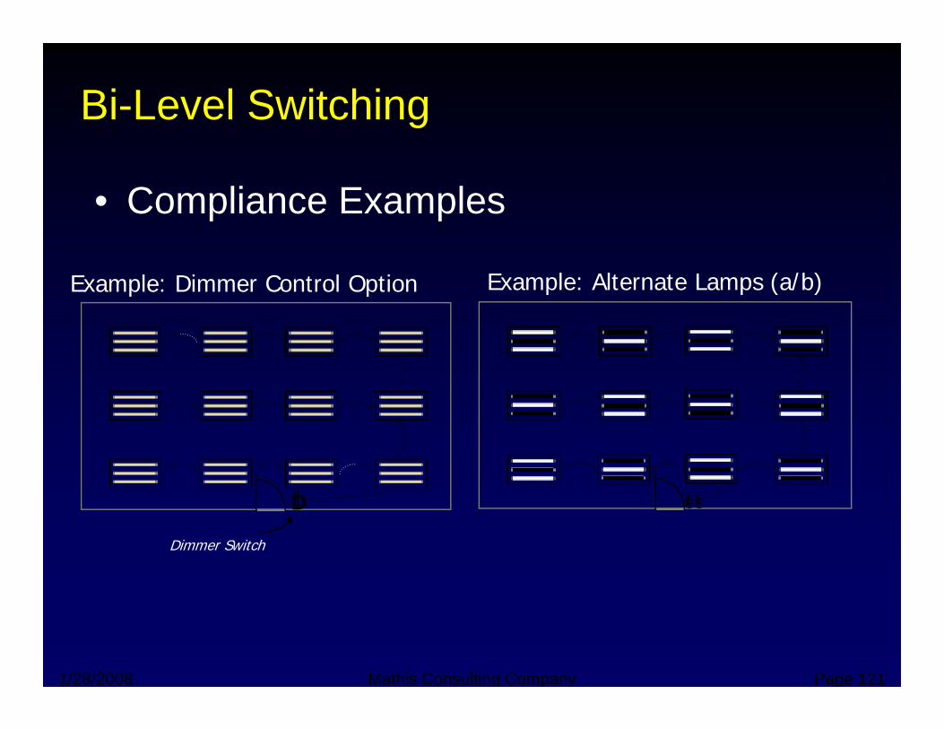
Bi-Level Switching
• Compliance Examples
Example: Alternate Lamps (a/b)Example: Dimmer Control Option
SSD SS
Dimmer Switch
D
1/28/2008 Mathis Consulting Company Page 121
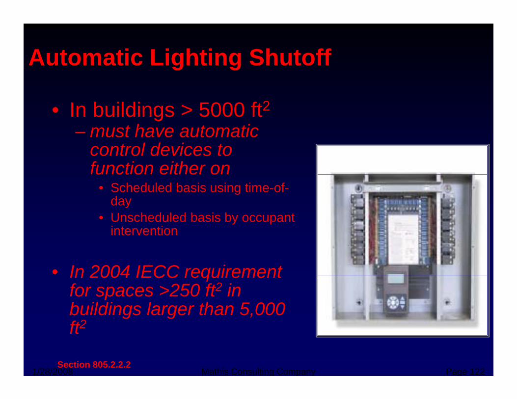
Automatic Lighting Shutoff
• In buildings > 5000 ft2h i– must have automatic
control devices to function either onu ct o e t e o
• Scheduled basis using time-of-day
• Unscheduled basis by occupant intervention
• In 2004 IECC requirementIn 2004 IECC requirement for spaces >250 ft2 in buildings larger than 5,000 ft2
1/28/2008 Mathis Consulting Company Page 122
ft2
Section 805.2.2.2
Occupant Override
• Where automatic time switch control devices i t ll d t l ith A t tiare installed to comply with Automatic
Lighting Shutoff, device shall be equipped with an override switching device that:with an override switching device that:– Readily accessbile– Located so that person using the device can see
the lights or area controlled by the switch– Manually operated– Allows lighting to remain on for no more than 2Allows lighting to remain on for no more than 2
hours when an override is initiated– Controls an area <5,000 square feet
1/28/2008 Mathis Consulting Company Page 123
• Some ExceptionsSection 805.2.2.2.1
Holiday scheduling
• If automatic time switch is installed:
– Automatic holiday scheduling feature that turns ff ll l d f t l t 24 h d thoff all loads for at least 24 hours and then
resumes to normally scheduled operation
• ExceptionsR il d i d ll– Retail stores and associated malls, restaurants, grocery stores, churches and theaters
1/28/2008 Mathis Consulting Company Page 124
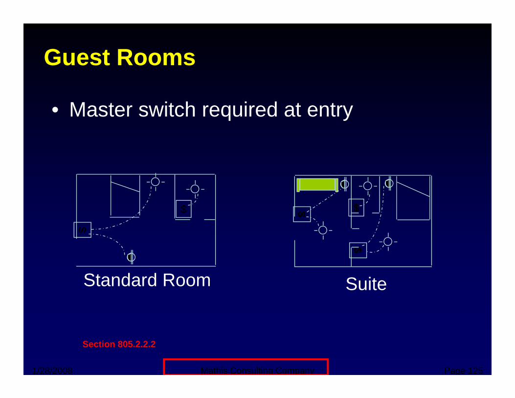
Guest Rooms
• Master switch required at entry
$$ $$$$
St d d R
$$
$$
Standard Room Suite
1/28/2008 Mathis Consulting Company Page 125
Section 805.2.2.2
Exterior Lighting Controlsg g
• Automatic switching or photocell controlsAutomatic switching or photocell controls shall be provided for all exterior lighting not intended for 24 hour operation.
• Automatic time switches shall have a• Automatic time switches shall have a combination– Seven-day and seasonal daylight program y y g p g
schedule adjustment– A minimum 4-hour power backup
1/28/2008 Mathis Consulting Company Page 126
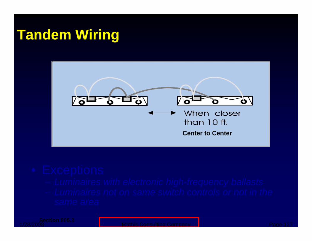
Tandem Wiring
Center to Center
E ti• Exceptions– Luminaires with electronic high-frequency ballasts– Luminaires not on same switch controls or not in the
1/28/2008 Mathis Consulting Company Page 127
same area
Section 805.3
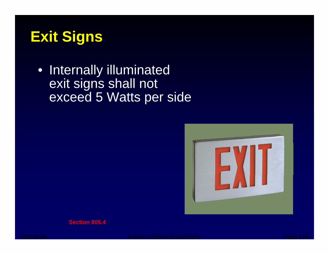
Exit Signs
• Internally illuminated it i h ll texit signs shall not
exceed 5 Watts per side
1/28/2008 Mathis Consulting Company Page 128
Section 805.4
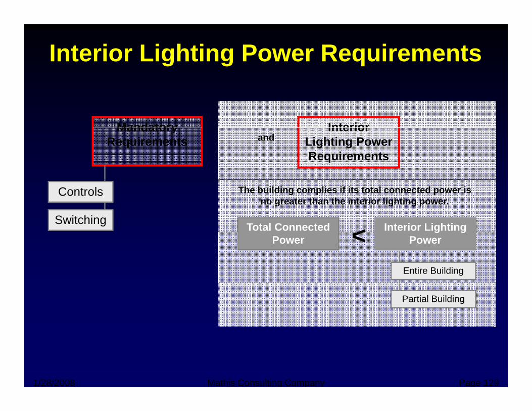
Interior Lighting Power Requirements
Mandatory InteriorMandatory Requirements
Interior Lighting Power Requirements
and
Controls
Switching Total Connected Interior Lighting <
The building complies if its total connected power is no greater than the interior lighting power.
Entire Building
Powerg g
Power<
Partial Building
1/28/2008 Mathis Consulting Company Page 129

Total Connected Power• Total connected lighting wattage includes:
– Lamp wattageBallast wattage– Ballast wattage
• Sources of bulb/ballast wattages– Manufacturer’s literature– Industry default tables
• ExceptionsS i li d di l d t l d h li hti– Specialized medical, dental, and research lighting
– Professional sports arena playing field lighting– Display lighting for gallery exhibits, museums, and
tmonuments– Guest room lighting in hotels, motels, boarding
houses, or similar buildingsE li hti t ti ll ff d i l
1/28/2008 Mathis Consulting Company Page 130
– Emergency lighting automatically off during normal building operation
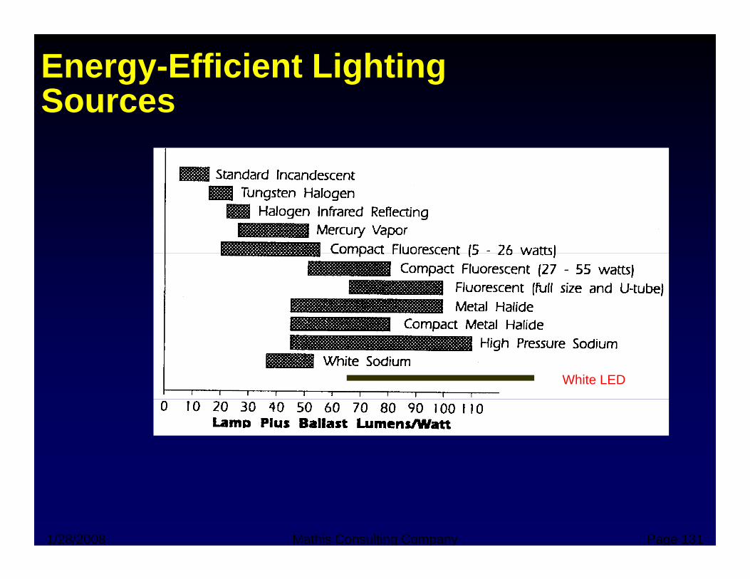
Energy-Efficient Lighting SourcesSources
White LED
1/28/2008 Mathis Consulting Company Page 131
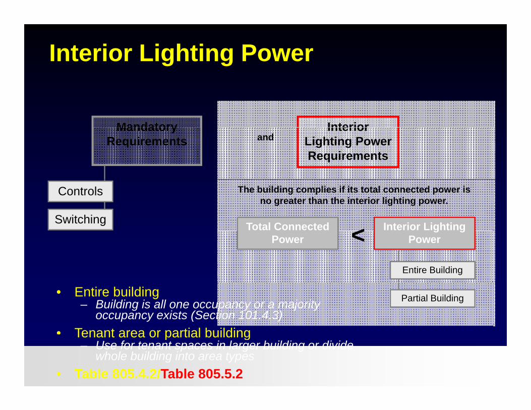
Interior Lighting Power
Mandatory InteriorMandatory Requirements
Interior Lighting Power Requirements
and
Controls
Switching Total Connected Interior Lighting <
The building complies if its total connected power is no greater than the interior lighting power.
Entire Building
Powerg g
Power<
Partial Building• Entire building– Building is all one occupancy or a majority
occupancy exists (Section 101.4.3)• Tenant area or partial building
1/28/2008 Mathis Consulting Company Page 132
Tenant area or partial building– Use for tenant spaces in larger building or divide
whole building into area types• Table 805.4.2/Table 805.5.2

What is the Interior Lighting Power Budget for this Building?Budget for this Building?
F t
Office A
FutureDevelopmentBath-
roomsOffice A:Office B:
400 ft2
850 ft2
Corridor
Retail A
Bathrooms:Corridor:Retail A:Retail B:
350 ft2
50 ft2
500 ft2
500 ft2
Office B
Retail BFuture: 350 ft2
Total Building Area = 3000 ft2
1/28/2008 Mathis Consulting Company Page 133
Does the Building Comply?
• Determine the total connected power in watts f th d li htifor the proposed lighting
• Determine the interior lighting power budget for the entire building or space
• Building complies if:g p– Interior lighting power budget - total connected
power = 0
1/28/2008 Mathis Consulting Company Page 134
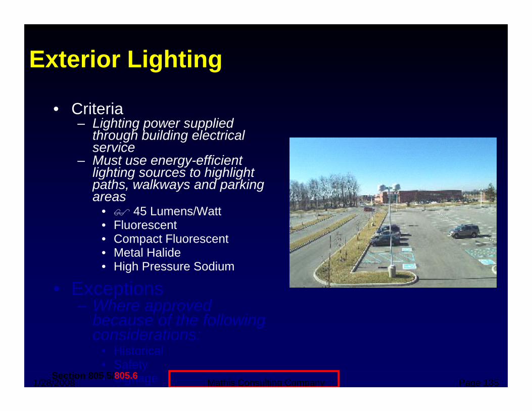
Exterior Lighting
• Criteria– Lighting power supplied g g p pp
through building electrical service
– Must use energy-efficient lighting sources to highlight
th lk d kipaths, walkways and parking areas
• 45 Lumens/Watt• Fluorescent• Compact Fluorescent• Metal Halide• High Pressure Sodium
E ti• Exceptions– Where approved
because of the following considerations:
1/28/2008 Mathis Consulting Company Page 135
considerations:• Historical• Safety• SignageSection 805.5/805.6
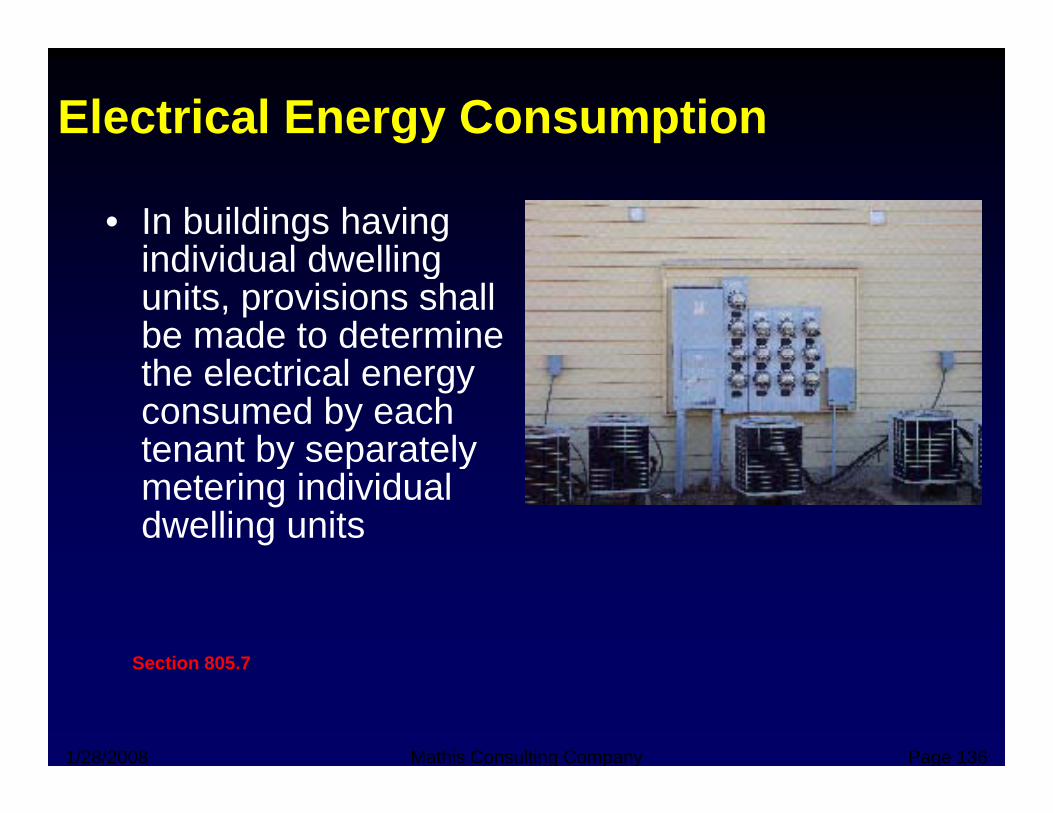
Electrical Energy Consumption
• In buildings having individual dwellingindividual dwelling units, provisions shall be made to determine the electrical energy consumed by each tenant by separatelytenant by separately metering individual dwelling units
Section 805 7
1/28/2008 Mathis Consulting Company Page 136
Section 805.7
Conclusion?
• We can’t do it all in a dayW b– Web resources
– Future workshops – Plan review trainingPlan review training– Worked examples
• But we have to start somewhere!But we have to start somewhere!– Simple prescriptive techniques will be most
commonP f t h i ll i l– Performance techniques usually involve professionals with a license on the line
• AIA, PE, etc.
1/28/2008 Mathis Consulting Company Page 137
, ,
Energy Consumption in Commercial B ildi M tt !Buildings Matters!
M th h lf f• More than half of energy use is for HVAC and lightingg g
• Typical energy bill equals 25% of total qoperating costs
• Climate sensitive• Climate sensitivedesign and off-the-shelf technologies can
1/28/2008 Mathis Consulting Company Page 138
cut energy bill by 50%

Additional Resources
• www.thesciencebehind.com
• www energycodes gov/training/presentati• www.energycodes.gov/training/presentations.stm
• http://www.energycodes.gov/training/pdfs/iecc com wb pdf/iecc_com_wb.pdf
1/28/2008 Mathis Consulting Company Page 139
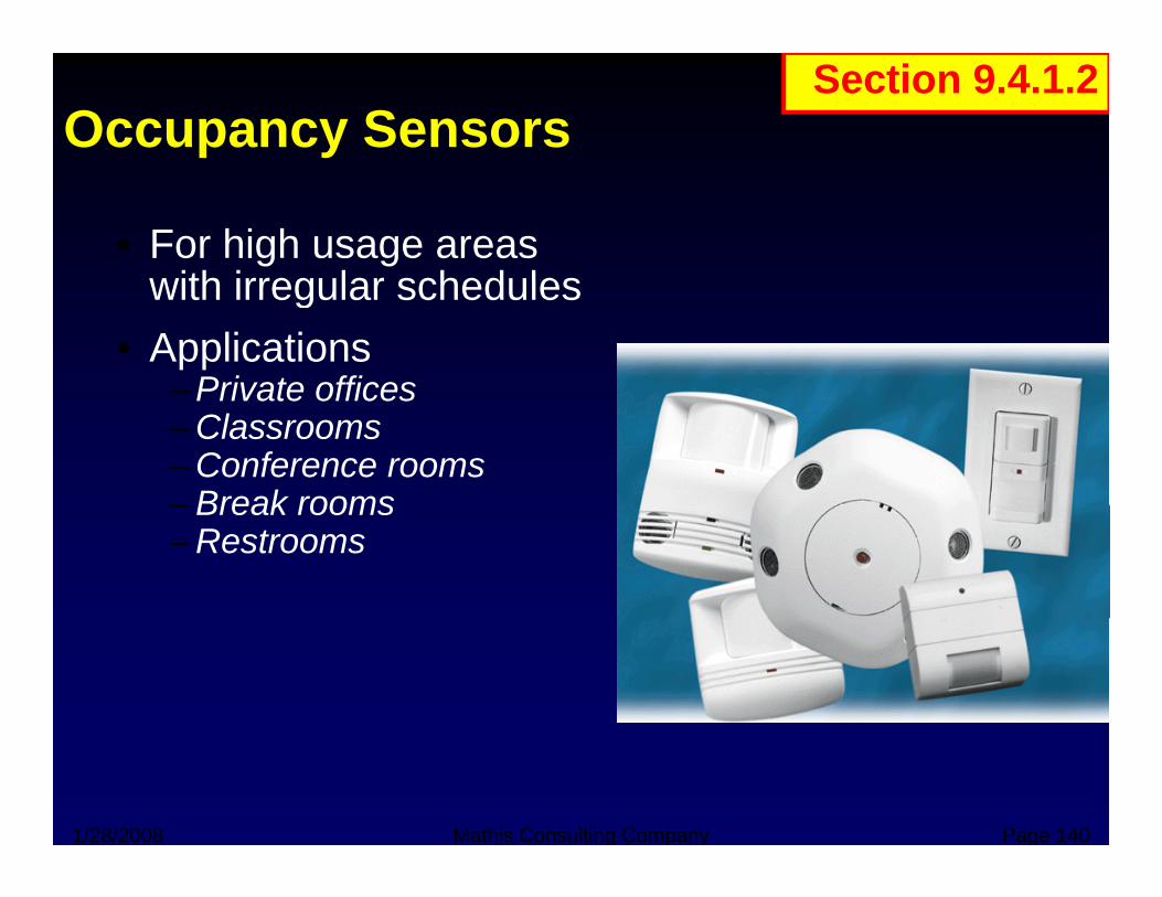
Occupancy SensorsSection 9.4.1.2
• For high usage areas with irregular scheduleswith irregular schedules
• Applications– Private offices– Private offices– Classrooms– Conference rooms– Break rooms– Break rooms– Restrooms
1/28/2008 Mathis Consulting Company Page 140
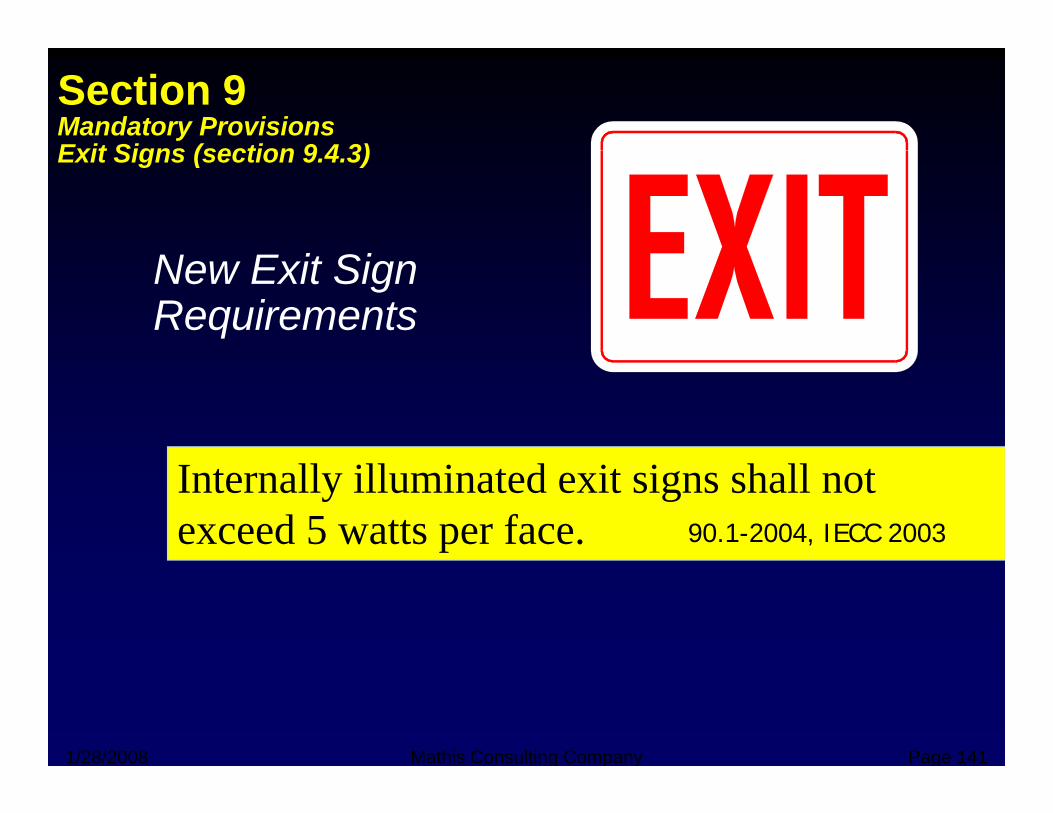
Section 9Mandatory ProvisionsExit Signs (section 9 4 3)Exit Signs (section 9.4.3)
SNew Exit SignRequirements
Internally illuminated exit signs shall not exceed 5 watts per face. 90.1-2004, IECC 2003
1/28/2008 Mathis Consulting Company Page 141