Embed Size (px)
Citation preview

1
2012 NC Residential Energy Code
Effective Use of the North Carolina Energy Conservation Code
The North Carolina Energy Conservation Code (NCECC) is a statewide enforced code that regulates minimum energy conservation requirements for new buildings, additions and renovations to existing buildings
The NCECC addresses energy conservation requirements for all aspects of energy uses in both commercial and residential construction, including heating and ventilating, lighting, water heating, and power usage for appliances and building systems.

2
North Carolina 2012Residential Code
January 1, 2012 Effective DateMarch 1, 2012 Enforceable DateBorn from the Model Codes▫ 2009 IECC is the Base▫ NC-Specific Changes▫ Adopted in 2012▫ Goal – 15% Energy Savings from 2006 IECC▫ 30% Savings with voluntary appendix
Arrangement and Format of the 2012 Energy CodeChapter 1 AdministrationChapter 2 DefinitionsChapter 3 Climate ZonesChapter 4 Residential Energy EfficiencyChapter 5 Commercial Energy EfficiencyChapter 6 Referenced Standards
NC Building Code: Chapter 11 Residential Energy Efficiency

3
Building Types Addressed For the Residential Energy Code
R-2, R-3, R-4, or townhouses, Residential structures three
stories or less in height
Detached one and two-family dwellings
Areas that Must Comply
New Construction & Change of Use
Heated and Cooled Space during “Normal Operation”▫ 50ºF or higher (heating)▫ 85ºF or lower (cooling)

4
N1101.1 Scope• This chapter shall regulate the design and
construction of buildings for the effective use of energy. This code is intended to provide flexibility to permit the use of innovative approaches and techniques to achieve the effective use of energy. This code is not intended to prevent the use of any material, method of construction, design or insulating system not specifically prescribed herein, provided that such construction, design or insulating system has been approved by the code official as meeting the intent of this code.
• Exception: Portions of the building envelope that do not enclose conditioned space.
N1101.1.2 Existing buildings.Except as specified in this chapter, this code shall not be used to require the removal, alteration or abandonment of, nor prevent the continued use and maintenance of, an existing building or building system lawfully in existence at the time of adoption of this code.
Historic buildings. Any building or structure that is listed in the State or National Register of Historic Places; designated as a historic property under local or state designation law or survey

5
N1101.1.3 Additions, alterations, renovations or repairs.Additions, alterations, renovations or repairs to an existing building, building system or portion thereof shall conform to the provisions of this code as they relate to new construction without requiring the unaltered portion(s) of the existing building or building system to comply with this code. Additions, alterations, renovations or repairs shall not create an unsafe or hazardous condition or overload existing building systems. An addition shall be deemed to comply with this code if the addition alone complies or if the existing building and addition comply with this code as a single building.
Exceptions: The following need not comply provided the energy use of the building is not increased:• Storm windows installed over existing fenestration.• Incidental repairs requiring a new sash or new glazing. • Existing ceiling, wall or floor cavities exposed during
construction provided that these cavities are filled with insulation.
• Construction where the existing roof, wall or floor cavity is not exposed.
• Reroofing for roofs where neither the sheathing nor the insulation is exposed. Roofs without insulation in the cavity and where the sheathing or insulation is exposed during reroofing shall be insulated either above or below the sheathing.

6
Exceptions continued
• Replacement of existing doors that separate conditioned space from the exterior shall not require the installation of a vestibule or revolving door, provided, however, that an existing vestibule that separates a conditioned space from the exterior shall not be removed,
• Alterations that replace less than 50 percent of the luminaires in a space, provided that such alterations do not increase the installed interior lighting power.
• Alterations that replace only the bulb and ballast within the existing luminaires in a space provided that the alteration does not increase the installed interior lighting power.
• Converting unconditioned attic space to conditioned attic space for one and two-family dwellings and townhouses. Ceilings shall be insulated to a minimum of R-30, walls shall be insulated to the exterior wall requirements in Tables 402.1.1 and 402.1.3 and follow backing requirements in Section 402.2.12.
101.4.4 Change in occupancy or use.Spaces undergoing a change in occupancy that would result in an increase in demand for either fossil fuel or electrical energy shall comply with this code. Where the use in a space changes from one use in Table 505.5.2 to another use in Table 505.5.2, the installed lighting wattage shall comply with Section 505.5.
101.4.5 Change in space conditioning. Any non-conditioned space that is altered to become conditioned space shall be required to be brought into full compliance with this code.Exception: See 101.4.3, exception 2.
101.4.6 Mixed occupancy. Where a building includes both residential and commercial occupancies, each occupancy shall be separately considered and meet the applicable provisions of Chapter 4 for residential and Chapter 5 for commercial.

7
Three Pathways to Compliance
• Prescriptive• Software Tradeoffs▫ RESCheck, Can only trade off the
0.30 Solar Heat Gain Coefficient to a .40 SHGC and no tradeoff for higher efficiency HVAC equipment
• Performance (computer modeling)
Component Trade-off Approach(such as RESCheck)
• Allows Trade-offs between components
• Whole building performance must be better than or equal to the minimum (with some exceptions)▫ SHGC of 0.30 is required for climate zones 3 and 4▫ Can trade-off up to .40 SHGC ▫ Envelope requirements may not be traded
off against HVAC

8
405.3 Performance-based compliance• Typically Determined by Home Energy Rating
or other building computer modeling▫ Compares proposed design with a code compliant
standard reference design• Has the most builder options• Most complex• Specifics covered in Section 405Simulated Performance Alternative(And at the end of this presentation)
N1101.10 Additional Voluntary Criteria for Increasing Residential Energy Efficiency. (Appendix 4)
Implementation of the increased energy efficiency measures is strictly voluntary at the option of the permit holder. The sole purpose of the appendix is to provide guidance for achieving additional residential energy efficiency improvements that have been evaluated to be those that are most cost effective for achieving an additional 15-20% improvement in energy efficiency beyond code minimums.

9
Key TerminologyFULLY ENCLOSED ATTIC FLOOR SYSTEM– The ceiling insulation is enclosed on all six sides by an air barrier system, such as taped drywall below, solid framing joists on the sides, solid blocking on the ends, and solid sheathing on top which totally enclose the insulation. This system provides for full depth insulation over the exterior walls.MASS WALL. Masonry or concrete walls having a mass greater than or equal to 30 pounds per square foot (146 kg/m2). solid wood walls having a mass greater than 20 pounds per square foot (98 kg/m2), and any other walls having a heat capacity greater than or equal to 6 Btu/ft2 *F[266 J/(m2*K)].HERS RATER. An individual that has completed training and been certified by RESNET (Residential Energy Services Network) Accredited Rating Provider.HIGH-EFFICACY LAMPS. Compact fluorescent lamps, T-8 or smaller diameter linear fluorescent lamps, or lamps with a minimum efficacy of:60 lumens per watt for lamps over 40 watts,50 lumens per watt for lamps over 15 watts to 40 watts, and40 lumens per watt for lamps 15 watts or less.
Key Terminology Cont.PROPOSED DESIGN. A description of the proposed building used to estimate annual energy use for determining compliance based on total building performance.STANDARD REFERENCE DESIGN. A version of the proposed design that meets the minimum requirements of this code and is used to determine the maximum annual energy use requirement for compliance based on total building performance.R-VALUE (THERMAL RESISTANCE). The inverse of the time rate of heat flow through a body from one of its bounding surfaces to the other surface for a unit temperature difference between the two surfaces, under steady state conditions, per unit area (h x ft2 x °F/Btu) [(m2 x K)/W].SEMI-CONDITIONED SPACE A space indirectly conditioned within the thermal envelope that is not directly heated or cooled. For energy purposes, semi-conditioned spaces are treated as conditioned spacesU-FACTOR (THERMAL TRANSMITTANCE). The coefficient of heat transmission (air to air) through a building component or assembly, equal to the time rate of heat flow per unit area and unit temperature difference between the warm side and cold side air films (Btu/h x ft2 x °F) [W/(m2 x K)].

10
Key Terminology Cont.ACH50. Air Changes per Hour of measured air flow in relation to the building volume while the building is maintained at a pressure difference of 50 Pascals.BPI ENVELOPE PROFESSIONAL. An individual that has successfully passed the Building Performance Institute written and field examination requirements for the Building Envelope certification.BUILDING THERMAL ENVELOPE. The basement walls, exterior walls, floor, roof, and any other building element that enclose conditioned space. This boundary also includes the boundary between conditioned space and any exempt or unconditioned space.CFM25. Cubic Feet per minute of measured air flow while the forced air system is maintained at a pressure difference of 25 Pascals (0.1 inches w.p.)CFM50. Cubic Feet per Minute of measured air flow while the building is maintained at a pressure difference of 50 Pascals (0.2 inches w.p.).
Key Terminology Cont.CLOSED CRAWL SPACE. A foundation without wall vents that uses air sealed walls, ground and foundation moisture control, and mechanical drying potential to control crawl space moisture. Insulation may be located at the floor level or at the exterior walls.CODE OFFICIAL. The officer or other designated authority charged with the administration and enforcement of this code, or a duly authorized representative.CONDITIONED FLOOR AREA. The horizontal projection of the floors associated with the conditioned space.CONDITIONED SPACE. For energy purposes, space within a building that is provided with heating and/or cooling equipment or systems capable of maintaining, through design or heat loss/gain, 50F (10C) during the heating season and 85F (29C) during the cooling season, or communicates directly with a conditioned space. For mechanical purposes, an area, room or space being heated or cooled by any equipment or appliance.FENESTRATION. Skylights, roof windows, vertical windows (fixed or moveable), opaque doors, glazed doors, glazed block and combination opaque/glazed doors. Fenestration includes products with glass and nonglass glazing materials.INFILTRATION. The uncontrolled inward air leakage into a building caused by the pressure effects of wind or the effect of differences in the indoor and outdoor air density or both.INSULATING SHEATHING. An insulating board with a core material having a minimum R-value of R-2.

11
SECTION 302DESIGN CONDITIONS
302.1 Interior design conditions. The interior design temperatures used for heating and cooling load calculations shall be a maximum of 72ºF (22ºC) for heating and minimum of 75ºF (24ºC) for cooling.
Section 301 2012 IECC Climate Zones
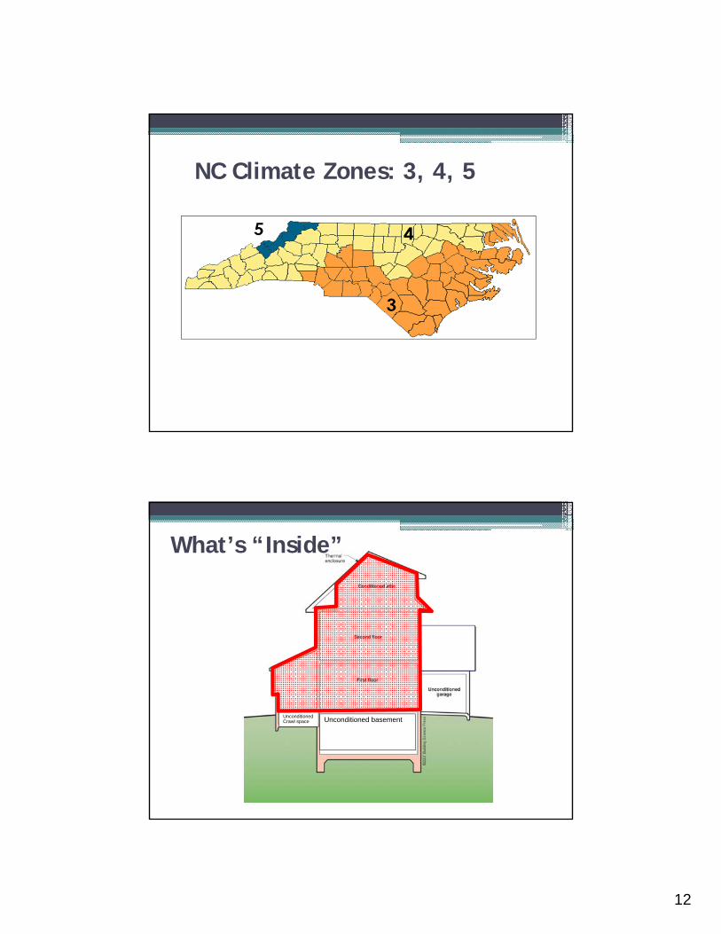
12
NC Climate Zones: 3, 4, 5
Unconditioned basementUnconditioned Crawl space
What’s “Inside”

13
What’s “Inside” #2: Redefined Building Envelope
N1101.4 Building thermal envelope insulationAn R-value identification mark shall be applied by the manufacturer to each piece of building thermal envelope insulation 12 inches or greater in width.
For sprayed polyurethane foam (SPF) insulation, the installed thickness of the areas covered and R-value of installed thickness shall be listed on the certification. The insulation installer shall sign, date and post the certification in a conspicuous location on the job site.

14
N1101.4.1 Blown or sprayed roof/ceiling insulation.
The thickness of blown-in or sprayed roof/ceiling insulation (fiberglass or cellulose) shall be written in inches (mm) on markers that are installed at least one for every 300 square feet (28 m2) throughout the attic space.
Material Identification/Labeling
Insulation and other materials must be clearly identified.
Installed thickness of insulation must be demonstrated.

15
Example Compliance Certificate
“Where blown-in or sprayed insulation is applied in the walls, floors and attics the installer shall provide a certification of installed density and R-value.”
N1101.5 Fenestration product rating
U-factors of fenestration products (windows, doors and skylights) shall be determined in accordance with NFRC 100 by an accredited, independent laboratory, and labeled and certified by the manufacturer.

16
Fenestration Performance
NFRC Rating for all Manufactured Fenestration▫ U-factor▫ SHGC▫ Air Leakage
N1101.9 Certificate required• On or in electrical service panel or inside the
kitchen cabinet or installed in the attic• Shall list R-values for all insulation ▫ Walls▫ Floors (slab and under-floor)▫ Attic/ ceiling▫ Basement and crawl space walls ▫ Ducts outside conditioned spaces
• Window U-factors and SHGC

17
ENERGY EFFICIENCY CERTIFICATEN1101.9
Builder, Permit Holder or Registered Design Professional Print Name:Signature:
Property Address:
Date:
Insulation Rating - List the value covering largest area to all that apply R-Value
Ceiling/roof: R-
Wall: R-
Floor: R-
Closed Crawl Space Wall: R-
Closed Crawl Space Floor: R-
Slab: R-
Basement Wall: R-
Fenestration:
U-Factor
Solar Heat Gain Coefficient(SHGC)
Building Air Leakage
o Visually inspected according to N1102.4.2.1 OR
o Building Air Leakage Test Results (Sec. N1102.4.2.2)ACH50 [Target: 5.0] or CFM50/SFSA [Target: 0.30]
Name of Tester / Company:
Date: Phone:
Ducts:
Insulation R-
Total Duct Leakage Test Result (Sect. N1103.2.2)(CFM25 Total/100SF) [Target: 6]
Name of Tester or Company:
Date: Phone:
Certificate to be displayed permanently
•APPENDIX E-1: RESIDENTIAL REQUIREMENTS•Energy Efficiency Certificate (Section N1101.9)
Building Envelope Requirements
Thermal Performance Criteria:▫ Air Leakage
Control▫ Fenestration▫ Insulation
Conditioned Space?

18
TABLE N1102.1INSULATION AND FENESTRATION REQUIREMENTS BY COMPONENT
CLIMATEZONE
FENESTRATION
U-FACTORb
SKYLIGHTb
U-FACTOR
GLAZEDFENESTRA
TIONSHGCb, e
CEILINGR-
VALUEk
WOODFRAME WALL
R-VALUE e
MASSWALL
R-VALUEi
FLOORR-VALUE
BASEMENTcWALL
R-VALUE
SLABdR-VALUE& DEPTH
CRAWLSPACEcWALL
R-VALUE
3 0.35 0.65 0.30 30 13 5/10 19 10/13f
0 5/13
4 0.35 0.60 0.30 38 or 30
cont. j
15, 13+2.5h
5/10 19 10/13
10 10/13
5 0.35 0.60 NR 38 or 30
cont. j
19, 13+5, or 15+3eh
13/17 30g 10/13
10 10/13
Notes from Previous R-Value Chart• For SI: 1 foot = 304.8 mm.
• a. R-values are minimums. U-factors and SHGC are maximums.
• b. The fenestration U-factor column excludes skylights. The SHGC column applies to all glazed fenestration.
• c. “10/13” means R-10 continuous insulated sheathing on the interior or exterior of the home or R-13 cavity insulation at the interior of the basement wall or crawl space wall.
• d. For monolithic slabs, insulation shall be applied from the inspection gap downward to the bottom of the footing or a maximum of 18 inches below grade whichever is less . For floating slabs, insulation shall extend to the bottom of the foundation wall or 24 inches, whichever is less. (See Appendix O) R-5 shall be added to the required slab edge R-values for heated slabs.
• e. R -19 fiberglass batts compressed and installed in a nominal 2 × 6 framing cavity is deemed to comply. Fiberglass batts rated R-19 or higher compressed and installed in a 2x4 wall is not deemed to comply.
• f. Basement wall insulation is not required in warm-humid locations as defined by Figure N1101.2(1 and 2) and Table N1101.2.
• g. Or insulation sufficient to fill the framing cavity, R-19 minimum.
• h. “13+5” means R-13 cavity insulation plus R-5 insulated sheathing. 15+3 means R-15 cavity insulation plus R-3 insulated sheathing. If structural sheathing covers 25 percent or less of the exterior, insulating sheathing is not required where structural sheathing is used. If structural sheathing covers more than 25 percent of exterior, structural sheathing shall be supplemented with insulated sheathing of at least R-2. 13+2.5 means R-13 cavity insulation plus R-2.5 sheathing.
• i. For Mass Walls, the second R-value applies when more than half the insulation is on the interior of the mass wall.
• j. R-30 shall be deemed to satisfy the ceiling insulation requirement wherever the full height of uncompressed R-30 insulation extends over the wall top plate at the eaves. Otherwise R-38 insulation is required where adequate clearance exists or insulation must extend to either the insulation baffle or within 1” of the attic roof deck.
• k. Table value required except for roof edge where the space is limited by the pitch of the roof, there the insulation must fill the space up to the air baffle.

19
R-Values
• Thermal resistance to heat flow
• The larger the number the better• The R-value of layers in a
construction can be added together
• Steel framing dramatically reduces the effective R-value
U-Factors• The amount of heat in Btus
(British thermal units) that flows each hour through one square foot, when there is a 1ºF temperature difference across the surface
• The smaller the number the better
U FactorR Value
- =-
1

20
Common R-values – Resistance to Conductive Heat Flow
Concrete0.2 per inch
½” Drywall0.5
Double-paned glass1.8
Low-e glass about 3.0Fiberglass insulation 3 to 4 per inchCellulose insulation 3.7 per inchExpanded polystyrene 4 per inchExtruded polystyrene 5 per inchIcynene foam 3.6 to 3.7 per inchPolyurethane foam 6.7 to 7.0 per inch
N1102.2.1 Ceilings with attic spaces. Ceilings with attic spaces over conditioned space shall meet the insulation requirements in Table N1102.1Exceptions: When insulation is installed in a fully enclosed attic floor system, as described in Appendix 1.B, R-30 shall be deemed compliant.In roof edge and other details such as bay windows, dormers, and similar areas where the space is limited, the insulation must fill the space up to the air baffle.

21
Exception for fully enclosed attic floor systems
N1102.2.2 Ceilings without attic spaces.
Where the design of the roof/ceiling assembly, including cathedral ceilings, bay windows and other similar areas, does not allow sufficient space for the required insulation, the minimum required insulation for such roof/ceiling assemblies shall be R-30. This reduction of insulation from the requirements of Section 402.1.1 shall be limited to 500 square feet of ceiling surface area.

22
402.2 Specific Insulation Requirements
Attic spaces – R-30 can substitute for R-38 with full height insulation over exterior walls (e.g. raised heel trusses)
Raised Heel Truss
Baffling to preventinsulation from blocking ventilation
Raised Heel Truss
Baffling to preventinsulation from blocking ventilation
N1102.2.3 Access hatches and doors. Horizontal Access hatches from conditioned spaces to unconditioned spaces (e.g., attics and crawl spaces) shall be weather-stripped and insulated to an R-10 minimum value, and vertical doors to such spaces shall be weather-stripped and insulated to R-5.

23
Exceptions: 1) Pull down stair systems shall be weather-stripped and insulated to an R-5 insulation value such that the insulation does not interfere with proper operation of the stair. Non-rigid insulation materials are not allowed. Additional insulation systems that enclose the stair system from above are allowed. Exposed foam plastic must meet the provisions of the Building Code or Residential Code, respectively.2) Full size doors that are part of the building thermal envelope and provide a passageway to unconditioned spaces shall meet the requirements of exterior doors in Section 403.2.4.
N1102.2.4 Mass walls.
Mass walls for the purposes of this chapter shall be considered above-grade walls of concrete block, concrete, insulated concrete form (ICF), masonry cavity, brick (other than brick veneer), earth (adobe, compressed earth block, rammed earth) and solid timber/logs.
MASS WALL. Masonry or concrete walls having a mass greater than or equal to 30 pounds per square foot (146 kg/m2). solid wood walls having a mass greater than 20 pounds per square foot (98 kg/m2), and any other walls having a heat capacity greater than or equal to 6 Btu/ft2 *F[266 J/(m2*K)].

24
N1102.2.5 Steel-frame ceilings, walls, and floors
Steel-frame ceilings, walls and floors shall meet the insulation requirements of Table 402.2.5 or shall meet the U-factor requirements in Table 402.1.3. The calculation of the U-factor for a steel-frame envelope assembly shall use a series-parallel path calculation method.
TABLE N1102.2. STEEL-FRAME CEILING, WALL AND FLOOR INSULATION (R-VALUE)
WOOD FRAMER-VALUE
REQUIREMENT
COLD-FORMED STEELEQUIVALENT R-VALUEa
Steel Truss Ceilingsb
R-30 R - 38 or R - 30 + 3 or R - 26 + 5R-38 R - 49 or R - 38 + 3R-49 R-38+5
Steel Joist Ceilingsb
R-30 R - 38 in 2×4 or 2×6 or 2×8R - 49 in any framing
R-38 R - 49 in 2×4 or 2×6 or 2×8 or 2×10Steel Framed Wall
R-13 R - 13 + 5 or R - 15 + 4 or R - 21 + 3 or R - 0 + 10R-19 R - 13 + 9 or R - 19 + 8 or R - 25 + 7R-21 R - 13 + 10 or R - 19 + 9 or R - 25 + 8
Steel Joist Floor
R-13 R - 19 in 2×6R - 19 + 6 in 2×8 or 2×10
R-19 R - 19 + 6 in 2×6R - 19 + 12 in 2×8 or 2×10
a. Cavity insulation R-value is listed first, followed by continuous insulation R-value.b. Insulation exceeding the height of the framing shall cover the framing.

25
N1102.2.6 FloorsInsulation must be in permanent contact with subfloor above
Max 18 inches between tension supports wires or other devices that hold the floor insulation in place.
Supports shall be no more than 6 inches from the end of the insulation
Enclosed floor cavity such as garage ceilings, cantilevers, or buildings on pilings with enclosed floor cavity with the insulation fully in contact with the lower air barrier. In the case the band boards will be insulated to maintain thermal envelope continuity
Exception to N1102.2.6
This floor cavity must be enclosed!

26
Cantilevered FloorsUsed to require ceiling R-value; now requires floor R-valueBut . . . how’s this house doing?
N1102.2.7 Basement Walls
• From top of basement wall down to 10 feet below grade or to basement floor which ever is less
•Walls in unconditioned basements must meet this requirement unless ceiling above is insulated

27
Basement Walls
• Inside or out?• Conditioned?• No insulation
required for masonry support
• Zone 3: R-5/13 Zone 4: R-10/ 13 Zone 5: R-10/ 13
N1102.2.8 Slab-on-grade floors.• Slab-on-grade floors with a
floor surface less than 12 inches (305 mm) below grade shall be insulated in accordance with Table 402.1.1.
• The top edge of the insulation installed between the exterior wall and the edge of the interior slab shall be permitted to be cut at a 45-degree (0.79 rad) angle away from the exterior wall.
• Slab edge insulation shall have 2” termite inspection gap consistent with Appendix 1.C of this code.

28
Why Insulate Slab Perimeters?
Slabs lose heat off
the edge!
rigidinsulation
dept
h finishgrade
CONDITIONEDSPACE
slab
rigidinsulation
dept
h finishgrade
CONDITIONEDSPACE
slab
CONDITIONEDSPACE
dept
h
protectionboard
flashing
finishgrade
slab
Prescriptive Packages - Slab Perimeter R-value

29
Termite Resistant Slab InsulationFloating slab technique
Floating slab
8” CMUStem wall
Cut-block
Foam insulation
Carpet tack strip
Drywall + molding
6 mil poly
N1102.2.9 Closed crawl space walls.
Where the floor above a closed crawl space is not insulated, the exterior crawlspace walls shall be insulated in accordance with table 402.1.1.
Wall insulation may be located in any combination of the outside and inside wall surfaces and within the structural cavities or materials of the wall system.

30
N1102.2.9 Closed Crawl space walls Cont.Wall insulation requires that the exterior wall band joist area of the floor frame be insulated. Wall insulation shall begin 3 inches below the top of the masonry foundation wall and shall extend down to 3 inches above the top of the footing or concrete floor, 3 inches above the interior ground surface or 24 inches below the outside finished ground level, whichever is less.
Crawl Space Wall Insulation Allowances for Termite Treatment and Inspection
• 3” outside between top of insulation and bottom of siding
• 6” Below-grade treatment
• 3” top of insulation and bottom of sill
• 3” clearance/ wicking space between bottom of insulation and top of ground surface, footing or concrete floor

31
N1102.2.9 Closed crawl space walls.
• Meet rules for closed crawl spaces• 4” max gap at top and bottom (or at least 24”
below grade)
3” from ground or 24: from
outside grade
Unvented Crawlspaces –The Ground Cover is Key
Crawl Space Walls:▫ Zone 3: R-5/ 13▫ Zone 4: R-10/ 13▫ Zone 5: R-10/ 13

32
N1102.2.10 Masonry
veneer. Insulation shall not be required on the horizontal portion of the foundation that supports a masonry veneer.
N1102.2.12 Framed cavity walls.The exterior thermal envelope wall insulation shall be installed in substantial contact and continuous alignment with the building envelope air barrier.
Insulation shall be substantially free from installation gaps, voids, or compression

33
Wall Insulation
R-values▫ Zone 3 : R-13
▫ Zone 4: R-15 or 13 + 2.5
▫ Zone 5: R-19 or13+5 or 15+3
Not every job has a perfect insulation installation….

34
Installation is Critically Important
Improper Installation!
Gaps and Voids
Dramatically reduce the average R-Value of the Assembly

35
All Insulations Are Susceptible
•Example – 1,000-square foot floor with R-19 insulation, but 6% gaps in the insulation. What is average R-value?
Gaps and Average R-value
Component R-value Area (A) A/ R-valueInsulation 19 940 49.5 Gaps 2 60 30.0
Total 1000 79.5 Average R-value 12.6 (Area/ Total A/R-value = 1,000/ 79.5)
•Btu’s/ deg - hr

36
N1102.2.12 Framed cavity walls Cont.
For framed walls, the cavity insulation shall be enclosed on all sides with rigid material or an air barrier material. Wall insulation shall be enclosed at the following locations:
Tubs, Showers, Stairs, Fireplace units, Attic Knee-Walls
All Attic knee-Walls of any type require solid backing enclosing the insulation

37
Solid Air-Barrier required in framed out areas such as fire-places
And Tubs and Showers

38
Solid Air-Barrier required behind showers and bath tubs
Sealing Framed-In Areas
•Avoid this problem

39
Floor framing under kneewalls
Minimum 1 3/8” solid-wood, insulated door, or minimum ½” foam insulation attached
to site-built door.
Install blocking between insulated attic floor and floor under heated space
Seal Garage Walls and Ceiling• Open trusses allow
air flow from above garage ceiling into home.
• If ceiling drywall is air tight and insulation is installed well, not so much a problem, But that’s a big IF!

40
Blocking & SheathingBlock stud cavities atchanges in ceiling height
Knee Walls Need Blocking
Blocking between joists needed to prevent air in attic from flowing under bonus room floor

41
Solid Framing: Blocking & Sheathing
Joist cavities under attic knee-walls must be blocked
Avoid These Problems

42
N1102.3 Fenestration. (Prescriptive).
N1102.3. U-factor. An area-weighted average of fenestration products shall be permitted to satisfy the U-factor requirements.
N1102.3.2 Glazed fenestration SHGC. An area-weighted average of fenestration products more than 50 percent glazed shall be permitted to satisfy the SHGC requirements.
N1102.3.3 Glazed fenestration exemption. Up to 15 square feet (1.4m2) of glazed fenestration per dwelling unit shall be permitted to be exempt from U-factor and SHGC requirements in Section 402.1.1.
Fenestration (windows/ glass)
• SHGC = Solar Heat Gain Coefficient• Maximum SHGC = 0.30 except zone 5 (Can be traded off up to .40 SHGCwith no requirement▫ Exemptions: 15 square feet of total glazing all glazing in doors
• Replacement fenestration must also meet max. SHGC = 0.30, max U-factor = 0.35, and max air leakage = 0.3 cfm

43
DP clear glass:SHGC = 0.6DP low-e: SHGC usually < 0.4
Solar Heat Gain Coefficient
N1102.3.4 Opaque door.
Opaque doors separating conditioned and unconditioned space shall have a maximum U-factor of 0.35. (U-Factor of .35 = R-Value of 3)
Exception: One side-hinged opaque door assembly up to 24 square feet (2.22 m2) in area is exempted from the U-factor requirement in Section 402.1.1. This exemption shall not apply to the U-factor alternative approach in Section 402.1.3 and the total UA alternative in Section 402.1.4.

44
N1102.3.5 Thermally isolated conditioned sunroom U-factor and SHGC.
The maximum fenestration U-factor shall be 0.40 and the maximum skylight U-Factor shall be 0.75. Sunrooms with cooling systems shall have a maximum fenestration SHGC of 0.40 for all glazing.
New windows and doors separating the sunroom from conditioned space shall meet the building thermal envelope requirements. Sunroom additions shall maintain thermal isolation; and shall be served by a separate heating or cooling system, or be thermostatically controlled as a separate zone of the existing system.
N1102.4.1 Building thermal envelope
The building thermal envelope shall be durably sealed with an air barrier system to limit infiltration. The sealing methods between dissimilar materials shall allow for differential expansion and contraction. For all homes, where present, the following shall be caulked, gasketed, weather-stripped or otherwise sealed with an air barrier material, or solid material consistent with Appendix 1.2.4 of this code:1. Blocking and sealing floor/ceiling systems and under knee walls open to unconditioned or exterior space.2. Capping and sealing shafts or chases, including flue shafts.3. Capping and sealing soffit or dropped ceiling areas.4. Sealing HVAC register boots and return boxes to subfloor or drywall.
45
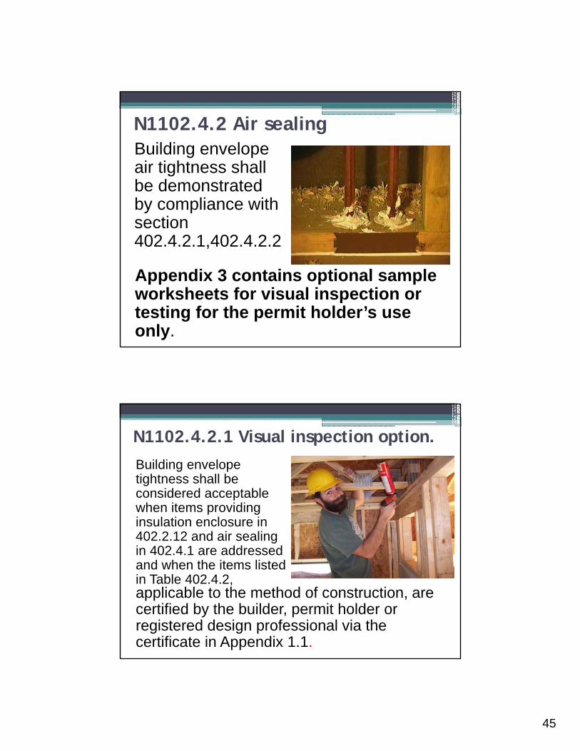
Building envelope air tightness shall be demonstrated by compliance with section 402.4.2.1,402.4.2.2
N1102.4.2 Air sealing
Appendix 3 contains optional sample worksheets for visual inspection or testing for the permit holder’s use only.
Building envelope tightness shall be considered acceptable when items providing insulation enclosure in 402.2.12 and air sealing in 402.4.1 are addressed and when the items listed in Table 402.4.2,
N1102.4.2.1 Visual inspection option.
applicable to the method of construction, are certified by the builder, permit holder or registered design professional via the certificate in Appendix 1.1.

46
COMPONENT CRITERIA
Ceiling/attic Sealants or gaskets provide a continuous air barrier system joining the top plate of framed walls with either the ceiling drywall or the top edge of wall drywall to prevent air leakage. Top plate penetrations are sealed.
For ceiling finishes that are not air barrier systems such as tongue-and-groove planks, air barrier systems,(for example, taped house wrap), shall be used above the finish
Note: It is acceptable that sealants or gaskets applied as part of the application of the drywall will not be observable by the code official
Walls Sill plate is gasketed or sealed to subfloor or slab.
Windows and doors Space between window and exterior door jambs and framing is sealed.
Floors (including above-garageand cantilevered floors)
Air barrier system is installed at any exposed edge of insulation.
Penetrations Utility penetrations through the building thermal envelope, including those for plumbing, electrical wiring, ductwork, security and fire alarm wiring, and control wiring, shall be sealed.
Garage separation Air sealing is provided between the garage and conditioned spaces. An air barrier system shall be installed between the ceiling system above the garage and the ceiling system of interior spaces.
Duct boots Sealing HVAC register boots and return boxes to subfloor or drywall.
Recessed lighting Recessed light fixtures are air tight, IC rated, and sealed to drywall.Exception—fixtures not penetrating the building envelope.
TABLE N1102.4.2 AIR BARRIER INSPECTION
Building envelope tightness shall be considered acceptable when items providing insulation enclosure in 402.2.12 and air sealing in 402.4.1 are addressed and when tested air leakage is less than or equal to one of the two following performance measurements1. 0.30 CFM50/Square Foot of Surface Area (SFSA) or 2. Five (5) air changes per hour (ACH50)
N1102.4.2.2 Testing option.

47
Testing shall be reported by the permit holder, a NC licensed general contractor, a NC licensed HVAC contractor, a NC licensed Home Inspector, a registered design professional, a certified BPI Envelope Professional or a certified HERS rater.
N1102.4.2.2 Testing option
Blower Door Components
•Wood or metal frame
•Air tight fabric
•Gauges
•Blower

48
Blower door test reveals 5,000 CFM50. The volume is: Area of each floor =
28ft x 48ft = 1,344 sq ft First floor volume = 1,344 sq ft x 9 ft =
12,096 cu ft Second floor volume = 1,344 sq ft x 8 ft =
10,752 cu ft Total volume = 22,848 cu ft
•8’•9’
Calculating ACH50
ACH50 = CFM50 x 60 Volume ACH50 = 5,000 CFM50 x 60 /
22,848 cu ft ACH50 = 13.1 ACH50Code Requirement:Five (5) air changes per hour(ACH50)
Calculating ACH50 Cont.

49
Calculating CFM50/sq ft
Area of walls = Perimeter x height = Perimeter = 2 * (28 + 48) = 152 lin ftWall height = 17 feet Area = 152 * 17 = 2,584
Floor area = 1,344 sq ft
Ceiling area = 1,344 sq ft
Total area = 5,272 sq ft
CFM50/ sq ft = 5,000/ 5,272 = 0.95
Code Requirement: 0.30 CFM50/Square Foot of Surface Area (SFSA)
Myth: Insulation Stops Air Leaks
Some types of insulation are no more effective at stopping air and cold drafts than an umbrella is at stopping the wind

50
Air Sealing Pre-Insulation
Seal penetrations in exterior wall sheathing
Dropped ceilings or chases adjacent to the building envelope

51
Sometimes the Holes Are BigBypasses -- Large holes that allow large volumes of
air to bypass the insulation
Sealing Air Leaks
Fiberglass Insulation Does Not Work!
Not an air seal Won’t fully fill gap Will fall out

52
Sealing ChasesSeal duct penetrations and between OSB panels and framing with caulking, mastic, or foam
MasticFoam
Poor Carpentry = Leaky Chases

53
Sealing Chases
Common Holes We Miss• Thermal Bypasses ▫ Chases for flues and ducts▫ Dropped soffits▫ Behind tubs, stairs, fireplaces▫ Cantilevers
• Penetrations▫ Plumbing▫ HVAC▫ Electrical
• Important Joints▫ Window flashing▫ Roof/wall intersections▫ Hip roof flashing▫ Deck/wall intersections▫ Etc.

54
Air Sealing Pre-InsulationSeal rough openings with
caulk, backer rod or special foam
Windows (Inside and Out)

55
When in Doubt – Caulk It!
Energy Code Air SealingPlumbing, electrical, HVAC and other penetrations must be sealed

56
Not My Job Syndrome?
Seal penetrations through insulated floors and attics
Energy Code Sealing – More Penetrations

57
Fire Blocking and Air Sealing Products
Air Leakage Controls?

58
N1102.4.5 Recessed lighting.
• Recessed luminaires installed in the building thermal envelope shall be sealed to limit air leakage between conditioned and unconditioned spaces.
• All recessed luminaires shall be sealed with a gasket or caulk between the housing and the interior wall or ceiling covering.
Typical Heating and Cooling Systems
Furnace
A/C Unit
Ductwork
Heating and Cooling Efficiency
Temperature &Humidity ControlsAuto Setback Thermostat
Duct Installationand Insulation
Pipe Insulation
Mechanical System Requirements

59
Mechanical & Equipment
• Duct Insulation• Duct Construction• Mechanical Sizing• Temperature Controls• HVAC Piping Insulation
Load Calculations403.6.1 Equipment Sizing.Heating and cooling equipment shall be sized in accordance with the North Carolina Mechanical Code.
302.1 Interior design conditions. The interior design temperatures used for heating and cooling load calculations shall be a maximum of 72ºF (22ºC) for heating and minimum of 75ºF (24ºC) for cooling.
403.6.2 Equipment Efficiencies. Equipment efficiencies shall comply with the current NAECA minimum standards.

60
Temperature & Humidity Control
Controls (Mandatory Requirements). At least one thermostat shall be provided for each separate heating and cooling system.
N1103.1.1 Programmable thermostat.
Where the primary heating system is a forced-air furnace, at least one thermostat per dwelling unit shall be capable of controlling the heating and cooling system on a daily schedule to maintain different temperature set points at different times of the day. This thermostat shall include the capability to set back or temporarily operate the system to maintain zone temperatures down to 55°F (13°C) or up to 85°F (29°C).

61
N1103.1.2 Heat pump supplementary heat (Mandatory Requirements).
• Heat pumps having supplementary electric-resistance heat shall have controls that, except during defrost, prevent supplemental heat operation when the heat pump compressor can meet the heating load.
•A heat strip outdoor temperature lockout shall be provided to prevent supplemental heat operation in response to the thermostat being changed to a warmer setting. The lockout shall be set no lower than 35F and no higher than 40oF.
Ductwork Systems

62
Supply and return ducts in unconditioned space and outdoors shall be in insulated to R-8. Supply ducts inside semi-conditioned space shall be insulated to R-4; return ducts inside conditioned and semi-conditioned space are not required to be insulated. Ducts located inside conditioned space are not required to be insulated other than as may be necessary for preventing the formation of condensation on the exterior of cooling ducts.
N1103.2.1 Insulation (Prescriptive).
All ducts, air handlers, filter boxes and building cavities used as ducts shall be sealed. Joints and seams shall comply with Part V –Mechanical, Section 603.9 of the North Carolina Residential Code.
N1103.2.2 Sealing (Mandatory Requirements).

63
Total duct leakage less than or equal to 6 CFM (12 L/min) per 100 ft2 (9.29 m2) of conditioned floor area served by that system when tested at a pressure differential of 0.1 inches w.g. (25 Pa) across the entire system, including the manufacturer’s air handler enclosure.
Duct tightness shall be verified as follows:
1. Duct systems or portions thereof inside the building thermal envelope shall not be required to be leak tested.
2. Installation of a partial system as part of replacement, renovation or addition does not require a duct leakage test.
Exceptions to testing requirements:
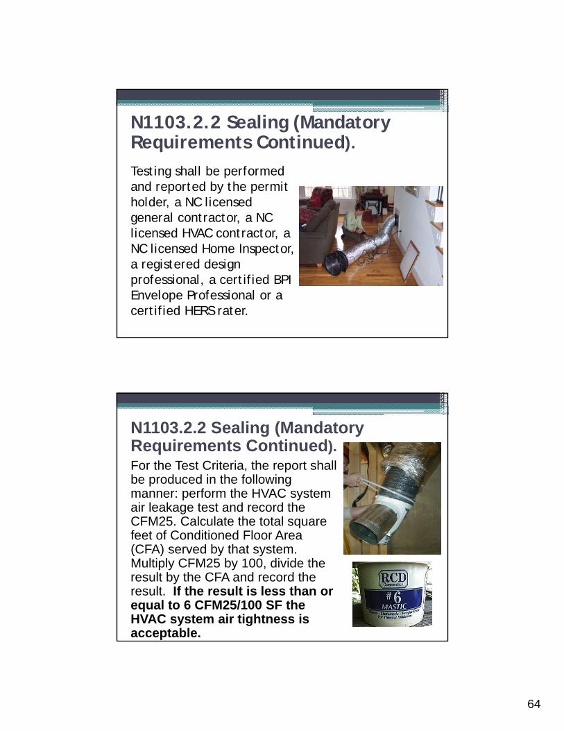
64
Testing shall be performed and reported by the permit holder, a NC licensed general contractor, a NC licensed HVAC contractor, a NC licensed Home Inspector, a registered design professional, a certified BPI Envelope Professional or a certified HERS rater.
N1103.2.2 Sealing (Mandatory Requirements Continued).
For the Test Criteria, the report shall be produced in the following manner: perform the HVAC system air leakage test and record the CFM25. Calculate the total square feet of Conditioned Floor Area (CFA) served by that system. Multiply CFM25 by 100, divide the result by the CFA and record the result. If the result is less than or equal to 6 CFM25/100 SF the HVAC system air tightness is acceptable.
N1103.2.2 Sealing (Mandatory Requirements Continued).

65
APPENDIX E-3CDuct sealing. Duct air leakage test (Section N1103.2.2)Sample Worksheet
•Complete one duct leakage report for each HVAC system serving the home:•Property Address: ________________________________________________________________
••HVAC System Number: _________ Describe area of home served: _____________________•CFM25 Total _________. Conditioned Floor Area (CFA) served by system: __________ s.f.•CFM25 x 100 divided by CFA = ____ CFM25/100SF (e.g. 100 CFM25x100/ 2,000 CFA = 5
CFM25/100SF)•Fan attachment location ___________________
•Company Name __________________________________________________________________•
•Contact Information:_______________________________________________________________•
•_______________________________________________________________________________•
•_____________________________________________________________________
• Signature of TesterDate
••Permit Holder, NC Licensed General Contractor, NC Licensed HVAC Contractor,
•NC Licensed Home Inspector, Registered Design Professional,•Certified BPI Envelope Professional, or Certified HERS Rater (circle one)
Leaky Ducts Leak Air!

66
Attic Supply?
How Big is the Duct?
Well, it depends…

67
Duct Air Sealing Is Required
No cloth duct tape allowed!
Must be UL 181 or mastic.
Seal with Durable Materials

68
Sealing Flex-duct Collar with Mastic
Attach flex-duct to take-off collar with strap
Plastic strap
Sealing Flex-duct Collar with Mastic
Apply mastic to seal flex-duct to collar and collar to plenum

69
Pull outer liner over sealed take-off; strap
Sealing Flex-duct Collar with Mastic
N1103.2.3 Building cavities (Mandatory Requirements).
Building framing cavities shall not be used as supply ducts.

70
N1103.3 Mechanical system piping insulation (Mandatory Requirements). Mechanical system piping capable of carrying fluids above 105°F (41°C) or below55°F (13°C) shall be insulated to a minimum of R-3.
N1103.4 Circulating hot water systems (Mandatory Requirements).All circulating service hot water
piping shall be insulated to at least R-2. Circulating hot water systems shall include an automatic or readily accessible manual switch that can turn off the hot water circulating pump when the system is not in use.
N1103.5 Mechanical ventilation (Mandatory Requirements).
Exhausts shall have automatic or gravity dampers that close when the ventilation system is not operating.
71
N1103.6 Equipment sizing and efficiency (Mandatory Requirements).
N1103.6.Equipment Sizing.Heating and cooling equipment shall be sized in accordance with the North Carolina Mechanical Code.
N1103.6.2 Equipment Efficiencies. Equipment efficiencies shall comply with the current NAECA minimum standards.
N1103.8.1 Heaters• All heaters shall be equipped with a readily
accessible on-off switch that is mounted outside of the heater to allow shutting off the heater without adjusting the thermostat setting.
• Gas-fired heaters shall not be equipped with constant burning pilot lights.
N1103.8 Pools, in-ground permanently installed spas (Mandatory).

72
N1103.8.2 Time switches. Time switches or other control method that can automatically turn off and on heaters and pumps according to a preset schedule shall be installed on all heaters and pumps. Heaters, pumps and motors that have built-in timers shall be deemed in compliance with this requirement.Exceptions:
• Where public health standards require 24-hour pump operation.•Where pumps are required to operate solar- and waste-heat-recovery pool heating systems.
N1103.8.3 Covers. Heated pools and in-ground permanently installed spas shall be provided with a vapor-retardant cover. Exception: Pools deriving over 70 percent of the energy for heating from site-recovered energy, such as a heat pump or solar energy source computed over an operating season.
Electrical Systems Metering
• Required on all “Dwelling Units”
• Separate electrical meters are required on each unit in multi-family and high rise
Apartment One
Apartment Two

73
N1104.1 Lighting equipment (Prescriptive).
A minimum of 75 percent of the lamps in permanently installed lighting fixtures shall be high-efficacy lamps.
SECTION 405SIMULATED PERFORMANCE ALTERNATIVE(Performance)
405.1 Scope. This section establishes criteria for compliance using simulated energy performance analysis. Such analysis shall include heating, cooling, and service water heating energy only. A North Carolina licensed design professional is required to perform the analysis.405.4.2 Compliance report. Compliance software tools shall generate a report that documents that the proposed design complies with Section 405.3.
74
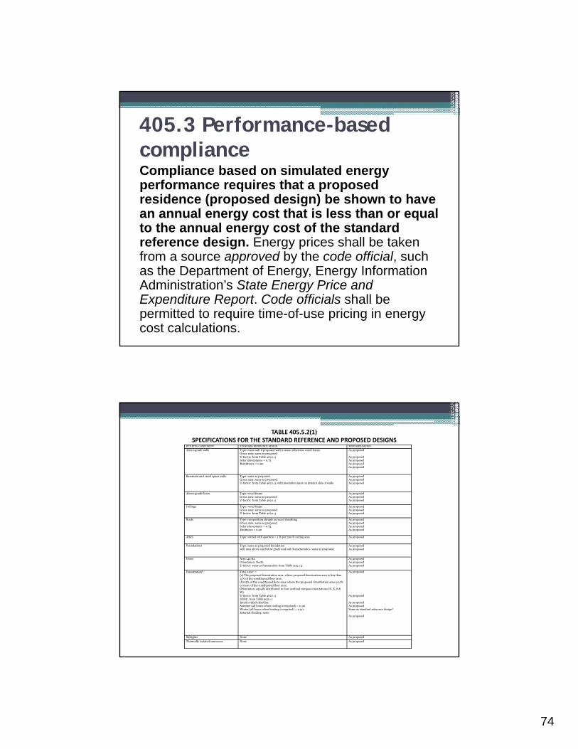
405.3 Performance-based complianceCompliance based on simulated energy performance requires that a proposed residence (proposed design) be shown to have an annual energy cost that is less than or equal to the annual energy cost of the standard reference design. Energy prices shall be taken from a source approved by the code official, such as the Department of Energy, Energy Information Administration’s State Energy Price and Expenditure Report. Code officials shall be permitted to require time-of-use pricing in energy cost calculations.
BUILDING COMPONENT STANDARD REFERENCE DESIGN PROPOSED DESIGN
Above-grade walls Type: mass wall if proposed wall is mass; otherwise wood frame.Gross area: same as proposedU-factor: from Table 402.1.3Solar absorptance = 0.75Remittance = 0.90
As proposed
As proposedAs proposedAs proposedAs proposed
Basement and crawl space walls Type: same as proposedGross area: same as proposedU-factor: from Table 402.1.3, with insulation layer on interior side of walls.
As proposedAs proposedAs proposed
Above-grade floors Type: wood frameGross area: same as proposedU-factor: from Table 402.1.3
As proposedAs proposedAs proposed
Ceilings Type: wood frameGross area: same as proposedU-factor: from Table 402.1.3
As proposedAs proposedAs proposed
Roofs Type: composition shingle on wood sheathingGross area: same as proposedSolar absorptance = 0.75Emittance = 0.90
As proposedAs proposedAs proposedAs proposed
Attics Type: vented with aperture = 1 ft2 per 300 ft2 ceiling area As proposed
Foundations Type: same as proposed foundation wall area above and below grade and soil characteristics: same as proposed.
As proposedAs proposed
Doors Area: 40 ft2Orientation: NorthU-factor: same as fenestration from Table 402.1.3.
As proposedAs proposedAs proposed
Fenestrationb Total areabc =(a) The proposed fenestration area; where proposed fenestration area is less than 15% of the conditioned floor area.(b) 15% of the conditioned floor area; where the proposed fenestration area is 15% or more of the conditioned floor area.Orientation: equally distributed to four cardinal compass orientations (N, E, S & W).U-factor: from Table 402.1.3SHGC: from Table 402.1.1Interior shade fraction:Summer (all hours when cooling is required) = 0.90Winter (all hours when heating is required) = 0.90External shading: none
As proposed
As proposed
As proposedAs proposedSame as standard reference designd
As proposed
Skylights None As proposed
Thermally isolated sunrooms None As proposed
TABLE 405.5.2(1)SPECIFICATIONS FOR THE STANDARD REFERENCE AND PROPOSED DESIGNS

75
Basic Requirements Recap:
• Insulation Requirements
• Air Leakage• Vapor
Retarders???• Materials and
Equipment Information
• Duct Insulation• Duct Construction
• Temperature Controls
• HVAC Piping Insulation
• Swimming Pools• Service Hot Water
Systems• Electrical
Renovations As Well

76
Key Provisions Recap• Insulation – correct R-values properly installed• Correct windows – check U-factor and Solar Heat
Gain Coefficient on NFRC label• Air sealing measures▫ Site-built windows, doors and skylights, window
and door jambs, behind tubs and showers on exterior walls, utility penetrations, dropped ceiling (e.g. dropped soffits) or chases, under and through kneewalls, attic access, recessed lamps
▫ Proper sealants (not “unstuffed” fiberglass)• Ducts sealed with proper materials• HVAC measures (sizing, heat pump controls)
APPENDIX E-4 ADDITIONAL VOLUNTARY CRITERIA FOR INCREASING ENERGY EFFICIENCY (High Efficiency Residential Option)
• Implementation of the increased energy efficiency measures is strictly voluntary at the option of the permit holder. The sole purpose of the appendix is to provide guidance for achieving additional residential energy efficiency improvements that have been evaluated to be those that are most cost effective for achieving an additional 15-20% improvement in energy efficiency beyond code minimums.

77
TABLE E-4AOPTIONAL INSULATION AND FENESTRATION REQUIREMENTS BY COMPONENT
CLIMATEFENESTRATI
ONSKYLIGHT
bGLAZED CEILING WOOD MASS FLOOR
BASEMENTc
SLABd CRAWL
ZONE U-FACTORb U-FACTORFENESTR
ATIONR-VALUEk
FRAME WALL
WALL R-VALUE WALL R-VALUE SPACEc
SHGCb, eR-VALUE
eR-VALUEi R-VALUE WALL
R-VALUE
3 0.32j 0.65 0.25 38
19, 13+5,
or 15+3eh
5/10 19 10/13f 5 10/13
4 0.32 0.6 0.25 38
19, 13+5,
or 15+3eh
5/10 19 10/13 10 10/13
5 0.32 0.6 (NR) 38
19, 13+5,
or 15+3eh
13/17 30g 10/13 10 15/19
Building Air Leakage Visually inspected according to N1102.4.2.1 (check box) OR
Building Air Leakage Test according to N1102.4.2.2 (check box). Show test value:
ACH50 [Target: 4.0], or CFM50/SFSA [Target: 0.24]
Name of Tester / Company:
Date: Phone:
Duct Insulation and SealingInsulation ValueDuct Leakage Test Result (Sect. N1103.2.2)
(CFM25 Total/100SF) [Target:4]Name of Tester or Company:
Date: Phone:
Table E-4C: Sample Confirmation Form for ADDITIONAL VOLUNTARY CRITERIA FOR INCREASING ENERGY EFFICIENCY (High Efficiency Residential Option

78
Lets Review the Key Items of the 2012 NC Residential Code
• Correct R-Values of Insulation for a given climate zone and circumstance.
• Proper Installation of Insulation i.e. no gaps, compression, low spots etc.
• Properly installed Air-Barrier • Extensive air-sealing of all penetrations and framing• Correct R-Value for Duct Insulation• Extensive duct sealing using mastic or UL 181 tape• Correct U-Factors and SHGC for windows• High Efficacy Bulbs in permanent fixtures
TABLE N1102.4.2 AIR BARRIER INSPECTION COMPONENT CRITERIA
Ceiling/attic Sealants or gaskets provide a continuous air barrier system joining the top plate of framed walls with either the ceiling drywall or the top edge of wall drywall to prevent air leakage. Top plate penetrations are sealed. For ceiling finishes that are not air barrier systems such as tongue-and-groove planks, air barrier systems,(for example, taped house wrap), shall be used above the finish Note: It is acceptable that sealants or gaskets applied as part of the application of the drywall will not be observable by the code official
Walls Sill plate is gasketed or sealed to subfloor or slab.
Windows and doors Space between window and exterior door jambs and framing is sealed.
Floors (including above-garageand cantilevered floors)
Air barrier system is installed at any exposed edge of insulation.
Penetrations Utility penetrations through the building thermal envelope, including those for plumbing, electrical wiring, ductwork, security and fire alarm wiring, and control wiring, shall be sealed.
Garage separation Air sealing is provided between the garage and conditioned spaces. An air barrier system shall be installed between the ceiling system above the garage and the ceiling system of interior spaces.
Duct boots Sealing HVAC register boots and return boxes to subfloor or drywall.
Recessed lighting Recessed light fixtures are air tight, IC rated, and sealed to drywall.Exception—fixtures not penetrating the building envelope.

79
APPENDIX E-2.2N1102.2.9 Closed crawl space walls. Insulation illustrations
APPENDIX E-2.3N1102.2.12 Framed cavity walls. Insulation enclosure – 1. Tubs

80
N1102.2.12 Framed cavity walls. Insulation enclosure – 2. Showers
N1102.2.12 Framed cavity walls. Insulation enclosure – 3. Stairs

81
N1102.2.12 Framed cavity walls. Insulation enclosure – 3. Stairs
N1102.2.12 Framed cavity wall.Insulation enclosure – 4. Direct vent gas fireplace
82
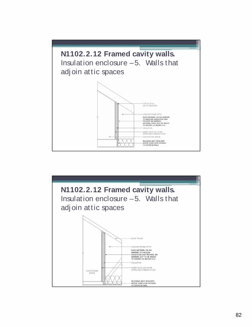
N1102.2.12 Framed cavity walls. Insulation enclosure – 5. Walls that adjoin attic spaces
N1102.2.12 Framed cavity walls. Insulation enclosure – 5. Walls that adjoin attic spaces

83
N1102.4.1 Building thermal envelope. – 1. Block and seal floor/ceiling systems
N1102.4.1 Building thermal envelope. – 1. Block and seal floor/ceiling systems

84
N1102.4.1 Building thermal envelope. – 1. Block and seal floor/ceiling systems
N1102.4.1 Building thermal envelope– 2. Cap and seal shafts and chases

85
N1102.4.1 Building thermal envelope. – 3. Cap and seal soffit or dropped ceiling
N1102.4.1 Building thermal envelope. – 4. Seal HVAC boot penetration – floor

86
Any Questions?