Embed Size (px)
Citation preview
www.cpi-worldwide.com
WORLDWIDETRADE JOURNALS FOR THE CONCRETE INDUSTRY
CPI
PRECAST CONCRETE ELEMENTS
A new approach to the production of hollowcore prestressed precast flooring
www.cpi-worldwide.com SPECIAL PRINT
nordimpianti_sonderdr2_en.qxp 11.04.2007 9:35 Uhr Seite 1
PRECAST CONCRETE ELEMENTS
2 CPI – Concrete Plant International – 2|2007 www.cpi-worldwide.com
Alan Clucas,Bison Concrete Products Limited, UK
As the Company continued to grow, pro-duction facilities were augmented to coverthe United Kingdom with new factories inScotland, the Midlands and the South-east. These factories were based on staticlong line bed manufacture with machinespassing over the beds. As the millenniumapproached Bison decided that it wasessential to reinvest in their productionand factories to maintain their marketleader status and a decision was taken toinvest £ 50 million (Euros 70 million) inupgrading existing plants and in building
a new hollow core production plant thatwould be the most advanced in Europe. This factory is on a 35 acre site at Swad-lincote Derbyshire in the centre of Eng-land and the economies achieved by theproduction process enable product to bedelivered competitively within a 200 mile(320 km) radius.
A new approach to production
The new factory at Swadlincote is de-signed to manufacture Bison Concretehollow core flooring products in a newway, combining the traditional 'long line'casting process with the circulating carou-
sel movement method. The manufacturingequipment for the whole project was supplied as a turnkey package by Nord-impianti Systems from Italy. The benefitsderived from this method are:
(a) The concrete batching and mixingplant and the concrete delivery sys-tem are closely integrated with theproduction casting machines, reduc-ing the distance in which mixed con-crete has to be conveyed to its pointof use.
(b) The production process machineslocated within the factory are at fixed
A new approach to the production of hollow core prestressed precast flooring
� Bison Concrete Products Limited, Swadlincote DE11 0BB, UK
Bison Concrete Products Ltd. has been a dominantcompany in the production and sale of precast,prestressed hollow core flooring in the UK formore than 60 years. Founded in 1919 the com-pany has enjoyed steady and sustained growth.In 1935 the invention by the Company of thepneumatic core revolutionised the manufacture ofhollow concrete floors; worldwide patents were
obtained and licensees appointed. Post WarBritain needed rebuilding and Bison was becom-ing a generic term for precast concrete. Newmethods of manufacture, notably prestressing,were being introduced and Bison was the firstcompany to exploit this new technology commer-cially.
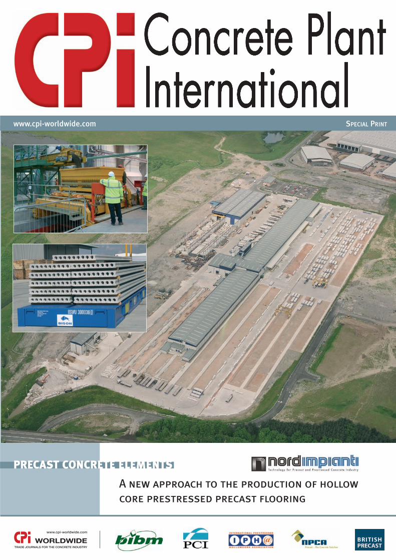
The new Bison plant is located at Swadlincote Derbyshire in the centre of England
Bison is combining the traditional 'longline' casting process with the circulatingcarousel movement method.
nordimpianti_sonderdr2_en.qxp 11.04.2007 9:35 Uhr Seite 2
3
PRECAST CONCRETE ELEMENTS
www.cpi-worldwide.com CPI – Concrete Plant International – 2|2007
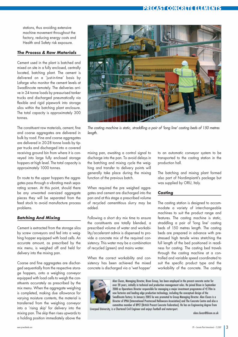
stations, thus avoiding extensivemachine movement throughout thefactory, reducing energy costs andHealth and Safety risk exposure.
The Process & Raw Materials
Cement used in the plant is batched andmixed on site in a fully enclosed, centrallylocated, batching plant. The cement isdelivered on a ‘just-in-time’ basis byLafarge who monitor the cement levels atSwadlincote remotely. The deliveries arri-ve in 24 tonne loads by pressurised tankertrucks and discharged pneumatically viaflexible and rigid pipework into storagesilos within the batching plant enclosure.The total capacity is approximately 300tonnes.
The constituent raw materials, cement, fineand coarse aggregates are delivered inbulk by road. Fine and coarse aggregatesare delivered in 20-28 tonne loads by tip-per trucks and discharged into a coveredreceiving ground bin from where it is con-veyed into large fully enclosed storagehoppers at high level. The total capacity isapproximately 1000 tonnes.
En route to the upper hoppers the aggre-gates pass through a vibrating mesh sepa-rating screen. At this point, should therebe any unwanted oversized aggregatepieces they will be separated from thefeed stock to avoid manufacture processproblems.
Batching And Mixing
Cement is extracted from the storage silosby screw conveyors and fed into a weig-hing hopper equipped with load cells. Anaccurate amount, as prescribed by themix menu, is weighed off and held fordelivery into the mixing pan.
Coarse and fine aggregates are dischar-ged sequentially from the respective stora-ge hoppers, onto a weighing conveyorequipped with load cells to weigh the con-stituents accurately as prescribed by themix menu. When the aggregate weighingis completed, making due allowance forvarying moisture contents, the material istransferred from the weighing conveyorinto a ‘rising skip' for delivery into themixing pan. The skip then rises upwards toa holding position immediately above the
mixing pan, awaiting a control signal todischarge into the pan. To avoid delays inthe batching and mixing cycle the weig-hing and transfer to delivery points willgenerally take place during the mixingfunction of the previous batch.
When required the pre weighed aggre-gates and cement are discharged into thepan and at this stage a prescribed volumeof recycled cementitious slurry may beadded.
Following a short dry mix time to ensurethe constituents are totally blended, aprescribed volume of water and workabi-lity/accelerant admix is dispensed to pro-vide a concrete mix of the required con-sistency. This water may be a combinationof recycled (green) and mains water.
When the correct workability and con-sistency has been achieved the mixedconcrete is discharged via a 'wet hopper’
to an automatic conveyor system to betransported to the casting station in theproduction hall.
The batching and mixing plant formedalso part of Nordimpianti's package butwas supplied by ORU, Italy.
Casting
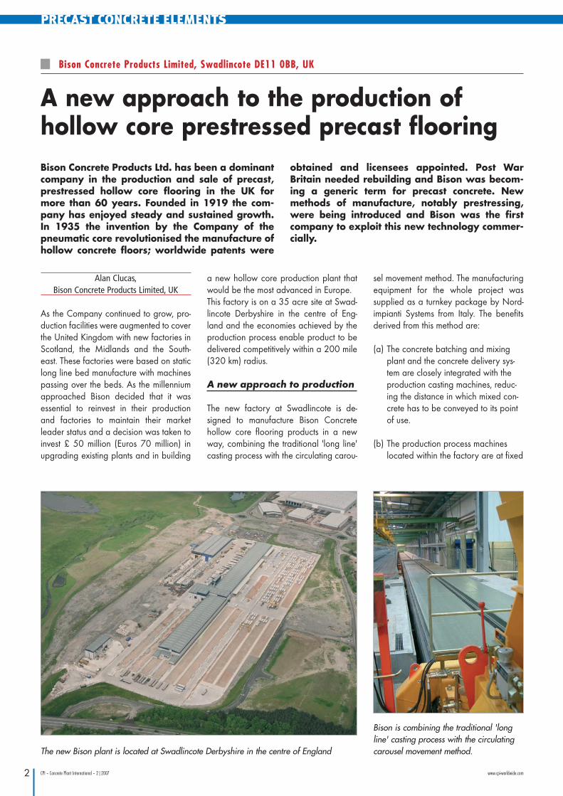
The casting station is designed to accom-modate a variety of interchangeablemachines to suit the product range andfeatures. The casting machine is static,straddling a pair of 'long line' castingbeds of 150 metres length. The castingbeds are prepared in advance with pre-stressed high tensile wires stretching thefull length of the bed positioned in readi-ness for casting. The casting bed travelsthrough the casting machine at a con-trolled and variable speed coordinated tosuit the specific product type and theworkability of the concrete. The casting
Alan Clucas, Managing Director, Bison Group, has been employed in the precast concrete sector forover 20 years, initially in technical and production management roles. He joined Bison in September2000 as Operations Director responsible for managing a major investment programme of €70m innew factories and leading edge production technology, including the conceptual design of theSwadlincote factory. In January 2005 he was promoted to Group Managing Director. Alan Clucas is aDirector of IPHA (International Prestressed Hollowcore Association) and The Concrete Centre and also acommittee member of BPCF (British Precast Concrete Federation). He has an Engineering degree from
Liverpool University, is a Chartered Civil Engineer and enjoys football and [email protected]
The casting machine is static, straddling a pair of 'long line' casting beds of 150 metreslength.
nordimpianti_sonderdr2_en.qxp 11.04.2007 9:35 Uhr Seite 3
PRECAST CONCRETE ELEMENTS
4 CPI – Concrete Plant International – 2|2007 www.cpi-worldwide.com
machine distributes and consolidates theconcrete in a mould, which is positionedimmediately above and in close contactwith the moving bed. The concrete is laidand compacted in the layers to providethe finished shape, encasing the pre-stressed wires. As the bed containing thefinished section passes further along thecasting station other machines and pres-ses carry out a variety of indentations andpressings to provide further features to theproduct.
The casting process inevitably results in asmall amount of waste concrete, general-ly at the start and finish of each bed andpossibly along part of the productionlength if there is a machine malfunction orinconsistency in the concrete. All wastematerial from the production process isrecycled.
On completion of casting the full line ofproducts the whole of the casting bed isthen moved sideways into the curing areaand replaced by another prepared bed torepeat the sequence.
Product Curing
When the bed arrives in the curing hall acloche, the full length and width of thebed, is automatically lowered onto thebed to cover the product. Installed alongthe full length beneath the cloche are aseries of tubes with outlet nozzles, the pur-pose of which is to distribute steam andcontain it over the product to acceleratethe curing process. When the cloche is inplace steam injectors automatically con-nect and provide a continuous supply ofsteam to the process.
Steam Raising Boiler House
The curing process is aided by the use ofsteam produced by natural gas firedsteam generating plant located within apurpose built boiler room located at oneend of the building. The steam plant com-prises two steam boilers capable of gene-rating up to 2000 kg/hr of steam at 12bar. This equates to approx. 1.55 MW(5.1 million BTU/hr) total boiler output or1.7MW (5.8 million BTU/hr) input.
The boiler plant is natural gas fired. Thegas supply is taken from the low-pressuresite main, which is boosted locally to pro-vide the boiler plant with a gas supplypressure of 300 mbar.
Each boiler has a dedicated chimney,which discharges over 1m above the high-est point of the adjacent building. Thesteam curing system was part of Nord-iimpianti's package and was supplied bytecnositer, Italy.
Cutting & Stripping
Following a suitable curing period the cloche is removed (for transfer to anotherincoming bed) and the high tensile wiresare de-tensioned.
It is at this point that a transponder isadded and glued to the unit. The trans-ponder technology adopted will allowclient engineers in the future to take areading off the transponder card andobtain general arrangements, unit detailsdesign, calculations and CDM data
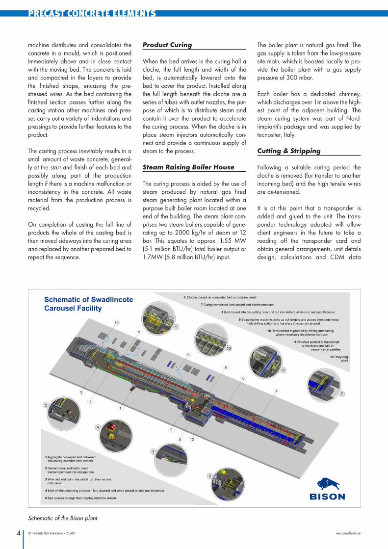
Schematic of the Bison plant
nordimpianti_sonderdr2_en.qxp 11.04.2007 9:35 Uhr Seite 4
5
PRECAST CONCRETE ELEMENTS
www.cpi-worldwide.com CPI – Concrete Plant International – 2|2007
should the building change use or loadingconditions.
The bed arrives at the cutting station andat this stage the 150 linear metre long sec-tion of concrete is cut into individual pro-duct lengths. The cutting machine is equip-ped with diamond edge cutting bladeswhich are cooled with water jets duringoperations.
The cementitious slurry created by thewater-cooled cutting process is conveyedby a drag chain system beneath groundto the recycling plant.
After the cutting process is completed thebed is then moved sideways to a strippingline. With the use of a purpose madedecanting machine the products are liftedand carried along the bed to a transferstation for conveyance to the secondstage production process and loading.The bed, when emptied, will transfer side-ways to the cleaning line.
Bed Cleaning & WasteDisposal
A small amount of cementitious waste,sweepings, bed end waste and unusableconcrete results from the production pro-cess. This is cleaned and collected by abed-cleaning machine and in some caseswith the use of a crane and waste skip.Waste materials from the bed cleaningare discharged into a drag chain systembelow ground to the recycling plantLarger pieces beyond the capacity of thecleaning machine are transported by skipto the crushing plant
The bed is then prepared for another cast.Pre-cut wires, set out in a template, arepaid out along the bed. The templates aresecured against the bed end abutmentsand the whole arrangement of wires isextended, mass stressed, to suit the nextplanned production lines.
The sequence continues repeating foreach bed.
Product Transfer. & SecondStage Processes – Dry Cutting
At the time of transferring products fromthe factory some individual pieces may
need further features forming or other pro-cesses unable to be completed prior tocuring and cutting. The automatic transferequipment establishes this requirementfrom the system database and directs theindividual products to the appropriatesecond stage (dry cut) machinery
In all cases where products are subse-quently saw cut the task is carried out insuitable enclosures, with cooling/dampen-ing jets to eliminate the potential for fugi-tive dust emissions. Cementitious slurryresulting from these tasks is channelledand discharged into the drag chainsystem below ground for conveyance tothe recycling plant.
Finished Product & Storage
If the product requires additional featurework, this is carried out by fully and semiautomatic diamond bladed saws whichare driven directly from the data embed-ded in a micro chip within the transponderattached to each unit.
These saws are housed within a soundproof enclosure which minimise any noiseemissions emanating from the site. Oncethe features are "cut" into the cured pro-duct the finished unit is then removed fromthe outload conveyor using a fork lift truckand stacked in load sequence order ontopallets designed specifically for the pro-duct.
Each fork lift truck is fitted with an LCDscreen which enables the driver to "pick"the right product in the right sequence offthe outload conveyor and transport it to itsdesignated pallet using the data from thetransponder sent by WIFI to each truck.The specially designed and certificatedpallets will enable Bison to utilise any formof Rail, Road or Sea transportation nowand in the future.
Two CMR straddle cranes were purchas-ed through Techmart International Ltd.Each crane can lift a pallet with a com-plete load of hollowcore and either placeit in the appropriate stockyard position or,conversely retrieve it from the stockyard toplace it on a road trailer, ready fordespatch. The combination of deliverypallet and straddle crane greatly in-creases handling efficiency and therebyreduces costs.
Batching Plant & MachineryClean Down
At the end of a production shift or after acasting machine change residue of con-crete or cement slurry is washed off withhigh pressure water and this water istaken by the drag chain system belowground to the recycling plant.
Recycled Products
Wet Recycling Plant
Adjacent to the batching plant is the wetconcrete recycling plant which takes:
• Unwanted or waste concrete in itsplastic state
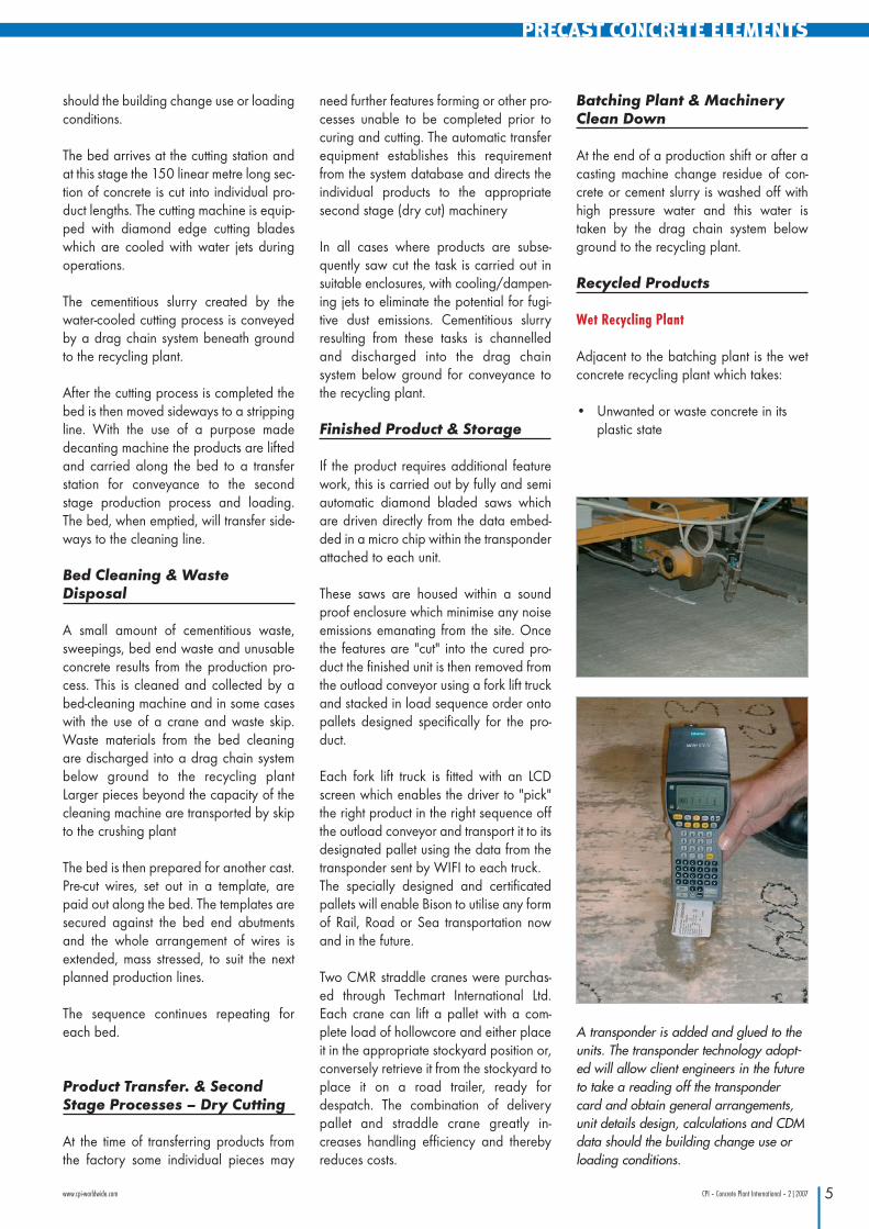
A transponder is added and glued to theunits. The transponder technology adopt-ed will allow client engineers in the futureto take a reading off the transpondercard and obtain general arrangements,unit details design, calculations and CDMdata should the building change use orloading conditions.
nordimpianti_sonderdr2_en.qxp 11.04.2007 9:35 Uhr Seite 5
PRECAST CONCRETE ELEMENTS
6 CPI – Concrete Plant International – 2|2007 www.cpi-worldwide.com
• Cementitious slurry from the batchingplant and production machinerywash down
• Saw cutting slurry from the saw sta-tion and dry cutting stations
• Sludge, slurry and small pieces ofgraded hardened waste from thebed cleaner
• Condensate from the steam curingprocess
All materials recycled arrive by the dragchain system.
The plant first separates the coarse materi-als from the fines. Depending on the qua-lity and grading of the coarse material achoice is made either to return it to thecoarse material feed stock at the batchingplant or transfer it to the on site crushingstation (Dry Recycling Plant).
The fines and liquids are pumped to a silofor further treatment to filter out reusable(green) water, leaving slurry for reuse inthe concrete mixing cycle. The greenwater is then transferred to a separate silofor reuse in the mixing plant, in addition tomains water, or for flushing out the chan-nels leading to the drag chains. The instal-lation saves approximately 1 million litresof mains water per annum and more than70% of the water used on site in produc-tion and other processes is recycled.
Should the production of slurry exceedthe capacity of the batching plant at anytime the slurry is diverted to a filter pressto be compressed into semi dry brick shapes that are disposed of at the dryrecycling plant. A detailed article aboutthe wet recycling plant can be found inissue CPI 4/2006.
Dry Recycling Plant
All waste, rejects and unsuitable products,bed end waste and hardened pieces be-yond the capacity of the wet recyclingplant are transferred by fork lift or skip tothe site crushing plant. The waste is thenreduced into smaller more manageable
pieces where the pre-stressed wire isremoved and segregated into a storagebin for onward recycling through specia-list metal recycling merchants.
The remaining material is reduced in sizeby crushing and grading for reuse in the
production process. At present some ofthe material is being processed for resaleas a Type 1 hardcore for ground worksbut the concept of the plant is that allwaste materials are reused within the pro-duction processes ensuring that there iszero wasteage.
�
Further information:
Bison Concrete Products LimitedTetron Point, William Nadine WaySwadlincote DE11 0BB, UKT +44 1283 817500F +44 1283 [email protected]
Wet concrete batching plant (see CPI4/2006 for details)
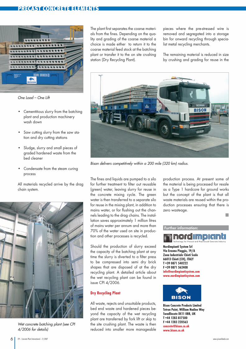
Bison delivers competitively within a 200 mile (320 km) radius.
One Load – One Lift
Nordimpianti System SrlVia Erasmo Piaggio, 19/AZona Industriale Chieti Scalo66013 Chieti (CH), ITALYT +39 0871 540222 F +39 0871 [email protected]
nordimpianti_sonderdr2_en.qxp 11.04.2007 9:35 Uhr Seite 6