Embed Size (px)
Citation preview
Inspection Guidelines for Condition Assessment of Concrete Structures
Doc ID
11963553
Custodian
Supervising Engineer Renewals, Asset Management Branch
Version Date
12 October 2014
Accountabilities Framework
Level 1 - Manage Infrastructure Assets
Level 2 - Plan and Investigate Asset Renewals Next Review Date
25 November 2017
Print Date: 11/04/2017 WARNING: DOCUMENT UNCONTROLLED WHEN PRINTED PAGE 1 OF 116
Concrete Structures Condition Assessment Guidelines
(Business Rules)
12 October 2014
Revision - 1

Inspection Guidelines for Condition Assessment of Concrete Structures
Print Date: 11/04/2017 WARNING: DOCUMENT UNCONTROLLED WHEN PRINTED PAGE 2 OF 116
Water Corporation ABN 28 003 434 917
629 Newcastle Street, Leederville WA 6007
PO Box 100, Leederville WA 6902 Telephone: (08) 9420 2420
www.watercorporation.com.au © 2014 WATER CORPORATION
Document Status
Rev Prepared by Reviewed by Approved by Date
1.0 Venkat Coimbatore
Mafizul Islam Sam Lee Mohan Des McEwen
Janet Ham 24 November 2014
Inspection Guidelines for Condition Assessment of Concrete Structures
Print Date: 11/04/2017 WARNING: DOCUMENT UNCONTROLLED WHEN PRINTED PAGE 3 OF 116
FOREWORD
Inspection guidelines are prepared to ensure that the Corporation’s staff, consultants and contractors are informed as to the Corporation’s requirement on methodical approach to asset condition assessment.
Inspection guidelines are intended to promote uniformity so as to simplify inspection methodology and reporting practice. Corporation’s ultimate objective of the Guideline is the provision of safe and functional plant at minimum whole of life cost.
The Corporation inspection methods and assessments described in this guideline have evolved over a number of years as a result of design and field experience.
The concrete structures inspection experience by Main Roads, Western Australia is gratefully acknowledged. Research publications by civil engineering associations, construction agencies, durability consultants, inspection equipment manufacturers and suppliers are gratefully acknowledged and referenced in this document.
Deviation, on a particular method, from the inspection guidelines may be permitted in special circumstances, but only after consultation with and endorsement by the Renewals Planning, Supervising Engineer in the Corporation’s Asset Management Branch.
Users are invited to forward submissions for continuous improvement to the Supervising Engineer or Manager, Renewals Planning, Water Corporation who will consider these for incorporation into future revisions.
This document contains colour pictorials. For optimum resolution colour printing is recommended.
Janet Ham Renewals Planning Manager Asset Management Branch
Inspection Guidelines for Condition Assessment of Concrete Structures
Print Date: 11/04/2017 WARNING: DOCUMENT UNCONTROLLED WHEN PRINTED PAGE 4 OF 116
DISCLAIMER
This Guideline is intended solely for inspection of water and waste water infrastructure in operating areas in Western Australia where the Water Corporation has been licensed to provide water services subject to the terms and conditions of its Operating License. This Guideline is provided for use only by a suitably qualified professional inspector, engineer or technician who shall apply the skill, knowledge and experience necessary to understand the risks involved and undertake all infrastructure condition assessment work. Any interpretation of anything in this Guideline that deviates from the requirements specified in the project design drawings and construction specifications shall be resolved by reference to and determination by the design engineer. The Corporation accepts no liability for any loss or damage that arises from anything in the Guideline, including loss or damage that may arise due to the errors and omissions of any person. This document is prepared without the assumption of a duty of care by the Water Corporation. The document is not intended to be nor should it be relied on as a substitute for professional engineering design expertise or any other professional advice.
Users should use and reference the current version of this document.
© Copyright – Water Corporation: This standard and software is copyright. With the exception of use permitted by the Copyright Act 1968, no part may be reproduced without the written permission of the Water Corporation.
Inspection Guidelines for Condition Assessment of Concrete Structures
Print Date: 11/04/2017 WARNING: DOCUMENT UNCONTROLLED WHEN PRINTED PAGE 5 OF 116
TABLE OF CONTENTS
FOREWORD ......................................................................................................... 3
DISCLAIMER ........................................................................................................ 4
TABLE OF CONTENTS ........................................................................................ 5
BASIC UNIT CONVERSIONS .............................................................................. 9
GLOSSARY OF TERMS ..................................................................................... 10
ACRONYMS ....................................................................................................... 15
REFERENCES ................................................................................................... 17
ENGINEERING STANDARDS & DESIGN DOCUMENTS .................................. 20
OPERATIONAL SAFETY ................................................................................... 24
[I] Concrete Sample Handling During Breakout .................................................. 24
[II] Ladders .......................................................................................................... 24
[III] Roofs ............................................................................................................ 24
[IV] Chemicals ..................................................................................................... 24
1.0 PURPOSE & SCOPE ................................................................................... 25
2.0 CONCRETE PRE-INSPECTION PREPARATION ........................................ 28
2.1 Inspection Requirements .............................................................................. 28
2.2 Roles and Responsibilities ............................................................................ 29
2.3 Defects Notification ....................................................................................... 29
2.4 Inspection Data Interpretation ....................................................................... 30
3.0 LEVELS OF CONCRETE INSPECTION ...................................................... 31
3.1 Level 1 – Routine Operation and Maintenance Inspection ............................ 31
3.2 Divers Inspection – Potable Water Concrete Tanks & Reservoir .................. 31
3.2.1 Tank Cleaning and Standard Inspection by Divers .............................. 31
3.2.2 Tank Cleaning - Divers Qualifications .................................................. 32
3.2.3 Civil Inspection by Divers..................................................................... 32
3.2.4 Divers Qualifications ............................................................................ 33
3.2.5 Divers Inspection Report ..................................................................... 33
3.2.6 Divers Condition Rating Outcome & AMB Interpretation ..................... 34
3.2.7 Inspection by Others - Water Corporation Personnel .......................... 34
3.3 Condition Rating Interpretation ..................................................................... 35
3.4 Level 2 - Formalised Inspection .................................................................... 37
3.4.1 Calibration of Inspection Gauges ......................................................... 38
3.4.2 Qualification of Level 2 Inspectors ....................................................... 38
Inspection Guidelines for Condition Assessment of Concrete Structures
Print Date: 11/04/2017 WARNING: DOCUMENT UNCONTROLLED WHEN PRINTED PAGE 6 OF 116
3.5 Level 3 – Detailed Investigation .................................................................... 38
3.5.1 Aim of Level 3 Inspection..................................................................... 39
3.5.2 Scope of a Level 3 Inspection .............................................................. 39
3.5.3 Outputs of a Level 3 Inspection ........................................................... 39
3.5.4 Qualification of Level 3 Inspectors ....................................................... 40
4.0 EXPOSURE ENVIRONMENT FOR POTABLE WATER & WASTE WATER ASSETS .............................................................................................................. 42
4.1 Exposure Environment for Water Corporation Assets ................................... 42
5.0 REBAR CORROSION & CONCRETE DETERIORATION MECHANISMS... 45
5.1 Rebar Corrosion - Mechanism ...................................................................... 45
5.2 Rebar Corrosion Classification ...................................................................... 46
5.2.1 Classification 1 .................................................................................... 46
5.2.2 Classification 2 .................................................................................... 46
5.2.3 Classification 3G .................................................................................. 47
5.2.4 Classification 3L .................................................................................. 47
5.2.5 Classification 4G .................................................................................. 47
5.2.6 Classification 4L .................................................................................. 48
5.2.7 Classification 5G .................................................................................. 48
5.2.8 Classification 6 .................................................................................... 48
5.3 General ......................................................................................................... 49
5.4 Internal Factors ............................................................................................. 49
5.4.1 Sulphate Content ................................................................................. 49
5.4.2 Delayed Ettringite Formation ............................................................... 49
5.4.3 Chloride Content .................................................................................. 50
5.4.4 Alkali Aggregate Reaction ................................................................... 50
5.5 External Factors ............................................................................................ 51
5.5.1 Carbonation ......................................................................................... 51
5.5.2 Chloride Attack .................................................................................... 51
5.5.3 Sulphate Attack ................................................................................... 51
5.5.4 Chemical Attack ................................................................................... 52
5.5.5 Mechanical Damage ............................................................................ 52
5.5.6 Fire Damage ........................................................................................ 52
5.5.7 Leaching .............................................................................................. 52
5.5.8 Restrained movement ......................................................................... 52
5.6 Design and Construction Factors .................................................................. 52
5.6.1 Poor Design ......................................................................................... 52
Inspection Guidelines for Condition Assessment of Concrete Structures
Print Date: 11/04/2017 WARNING: DOCUMENT UNCONTROLLED WHEN PRINTED PAGE 7 OF 116
5.6.2 Inadequate structural design ............................................................... 52
5.6.3 Insufficient reinforcement cover ........................................................... 53
5.6.4 Poor detailing ....................................................................................... 53
5.6.5 Poor Construction Practice .................................................................. 53
5.6.6 Improper Curing ................................................................................... 53
5.6.7 Improper Concrete Consolidation ........................................................ 53
5.6.8 Improper Casting Techniques .............................................................. 53
5.6.9 Improper Construction Sequence ........................................................ 54
5.7 Formation and Types of Cracks .................................................................... 54
6.0 DETAILED CONCRETE INSPECTION TECHNIQUES ................................ 58
6.1 Visual Inspection ........................................................................................... 58
6.2 Delamination Survey ..................................................................................... 58
6.3 Concrete Breakout ........................................................................................ 59
6.4 Covermeter Survey ....................................................................................... 60
6.5 Rebound Hammer Survey............................................................................. 61
6.6 Depth of Carbonation .................................................................................... 62
6.7 Half-Cell Potential Survey ............................................................................. 63
6.8 Concrete Resistivity ...................................................................................... 66
6.9 Cement Content and Type (Aggregate/Cement Ratio) ................................. 67
6.10 Concrete Compressive Strength ................................................................. 67
6.11 Apparent Volume of Permeable Voids (AVPV) ........................................... 67
6.12 Chloride Ion Penetration ............................................................................. 68
6.13 Sulphate Content ........................................................................................ 68
6.14 Sulphide Induced Corrosion ........................................................................ 69
6.15 Corrosion Rate Measurement ..................................................................... 69
6.16 Petrographic Analysis ................................................................................. 70
6.17 Ultrasonic Pulse Velocity............................................................................. 70
6.18 Summary of Commonly Used Concrete Inspection Techniques ................. 71
7.0 ASSET CONDITION RATING 1 - EXCELLENT ............................................ 75
8.0 ASSET CONDITION RATING 3 – VERY GOOD .......................................... 77
9.0 ASSET CONDITION RATING 5 - ACCEPTABLE ......................................... 78
10.0 ASSET CONDITION RATING 7 - BAD ....................................................... 80
11.0 ASSET CONDITION RATING 9 - POOR .................................................... 83
12.0 ASSET CONDITION RATING 10 – VERY POOR ...................................... 85
13.0 APPENDIX A – SERVICE LIFE PREDICTION ........................................... 88
13.1 Corrosion Process in Reinforced Concrete ................................................. 88
Inspection Guidelines for Condition Assessment of Concrete Structures
Print Date: 11/04/2017 WARNING: DOCUMENT UNCONTROLLED WHEN PRINTED PAGE 8 OF 116
13.2 Condition Limit States ................................................................................. 88
13.3 Initiation Phase ........................................................................................... 90
13.4 Corrosion Propagation Phase ..................................................................... 90
13.4.1 Prediction of RSL for Chloride Induced Corrosion ............................. 90
13.4.2 Prediction of RSL for Hydrogen Sulphide Induced Corrosion ............ 91
13.5 Chloride Induced Corrosion ........................................................................ 92
13.6 Carbonation Induced Corrosion .................................................................. 95
13.7 Hydrogen Sulphide Corrosion ..................................................................... 98
14.0 APPENDIX B – LEVEL 1 INSPECTION TEMPLATE FOR TANKS .......... 101
15.0 APPENDIX C - LEVEL 2 FORMALISED INSPECTION TEMPLATE ........ 109
16.0 APPENDIX D - LEVEL 3 – DETAILED INVESTIGATION TEMPLATE ..... 112
17.0 APPENDIX E - SURVEY LEGEND ........................................................... 115
Inspection Guidelines for Condition Assessment of Concrete Structures
Print Date: 11/04/2017 WARNING: DOCUMENT UNCONTROLLED WHEN PRINTED PAGE 9 OF 116
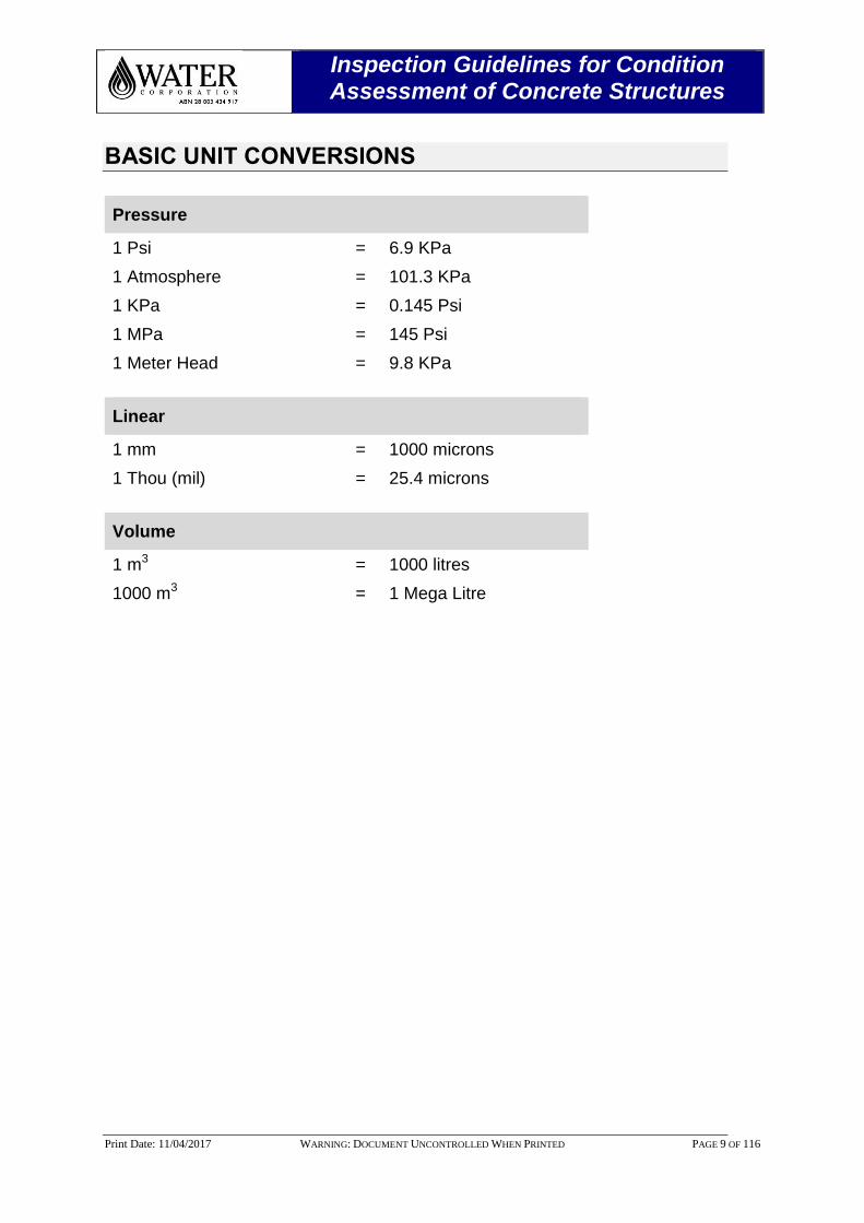
BASIC UNIT CONVERSIONS
Pressure
1 Psi = 6.9 KPa
1 Atmosphere = 101.3 KPa
1 KPa = 0.145 Psi
1 MPa = 145 Psi
1 Meter Head = 9.8 KPa
Linear
1 mm = 1000 microns
1 Thou (mil) = 25.4 microns
Volume
1 m3 = 1000 litres
1000 m3 = 1 Mega Litre
Inspection Guidelines for Condition Assessment of Concrete Structures
Print Date: 11/04/2017 WARNING: DOCUMENT UNCONTROLLED WHEN PRINTED PAGE 10 OF 116
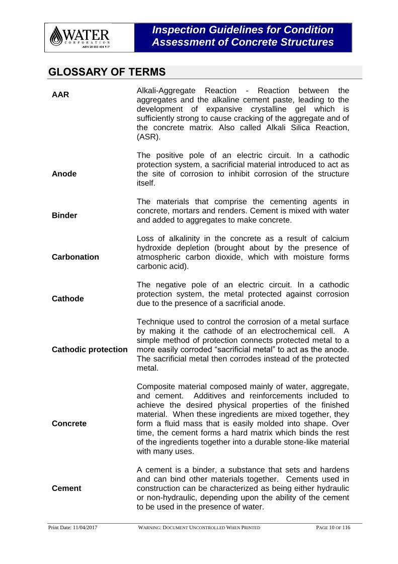
GLOSSARY OF TERMS
AAR Alkali-Aggregate Reaction - Reaction between the aggregates and the alkaline cement paste, leading to the development of expansive crystalline gel which is sufficiently strong to cause cracking of the aggregate and of the concrete matrix. Also called Alkali Silica Reaction, (ASR).
Anode
The positive pole of an electric circuit. In a cathodic protection system, a sacrificial material introduced to act as the site of corrosion to inhibit corrosion of the structure itself.
Binder
The materials that comprise the cementing agents in concrete, mortars and renders. Cement is mixed with water and added to aggregates to make concrete.
Carbonation
Loss of alkalinity in the concrete as a result of calcium hydroxide depletion (brought about by the presence of atmospheric carbon dioxide, which with moisture forms carbonic acid).
Cathode
The negative pole of an electric circuit. In a cathodic protection system, the metal protected against corrosion due to the presence of a sacrificial anode.
Cathodic protection
Technique used to control the corrosion of a metal surface by making it the cathode of an electrochemical cell. A simple method of protection connects protected metal to a more easily corroded “sacrificial metal” to act as the anode. The sacrificial metal then corrodes instead of the protected metal.
Concrete
Composite material composed mainly of water, aggregate, and cement. Additives and reinforcements included to achieve the desired physical properties of the finished material. When these ingredients are mixed together, they form a fluid mass that is easily molded into shape. Over time, the cement forms a hard matrix which binds the rest of the ingredients together into a durable stone-like material with many uses.
Cement
A cement is a binder, a substance that sets and hardens and can bind other materials together. Cements used in construction can be characterized as being either hydraulic or non-hydraulic, depending upon the ability of the cement to be used in the presence of water.
Inspection Guidelines for Condition Assessment of Concrete Structures
Print Date: 11/04/2017 WARNING: DOCUMENT UNCONTROLLED WHEN PRINTED PAGE 11 OF 116
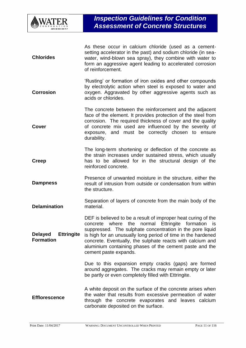
Chlorides
As these occur in calcium chloride (used as a cement-setting accelerator in the past) and sodium chloride (in sea-water, wind-blown sea spray), they combine with water to form an aggressive agent leading to accelerated corrosion of reinforcement.
Corrosion
‘Rusting’ or formation of iron oxides and other compounds by electrolytic action when steel is exposed to water and oxygen. Aggravated by other aggressive agents such as acids or chlorides.
Cover
The concrete between the reinforcement and the adjacent face of the element. It provides protection of the steel from corrosion. The required thickness of cover and the quality of concrete mix used are influenced by the severity of exposure, and must be correctly chosen to ensure durability.
Creep
The long-term shortening or deflection of the concrete as the strain increases under sustained stress, which usually has to be allowed for in the structural design of the reinforced concrete.
Dampness Presence of unwanted moisture in the structure, either the result of intrusion from outside or condensation from within the structure.
Delamination Separation of layers of concrete from the main body of the material.
Delayed Ettringite Formation
DEF is believed to be a result of improper heat curing of the concrete where the normal Ettringite formation is suppressed. The sulphate concentration in the pore liquid is high for an unusually long period of time in the hardened concrete. Eventually, the sulphate reacts with calcium and aluminium containing phases of the cement paste and the cement paste expands. Due to this expansion empty cracks (gaps) are formed around aggregates. The cracks may remain empty or later be partly or even completely filled with Ettringite.
Efflorescence
A white deposit on the surface of the concrete arises when the water that results from excessive permeation of water through the concrete evaporates and leaves calcium carbonate deposited on the surface.

Inspection Guidelines for Condition Assessment of Concrete Structures
Print Date: 11/04/2017 WARNING: DOCUMENT UNCONTROLLED WHEN PRINTED PAGE 12 OF 116
Ettringite
Ettringite is an expansive compound, is bigger in volume (is of smaller density) than it’s forming chemicals (calcium aluminate and sulphate taken together). Whenever it forms, it tends to cause tensile stresses within the concrete (or mortar) because it will tend to occupy a bigger volume than the volume occupied by its forming reactants.
Filler
The aggregates which mixed with the binder and water result in concrete. Typically categorized as coarse aggregate (crushed stone, gravel, etc.) and fine aggregate (commonly sand).
Galvanic action
Occurs when two dissimilar metals are placed together in solution. The most active metal will become an anode and corrode as a current passes between them.
In-situ concrete Concrete cast in its intended location.
Latent damage
Non-visible damage that is impairing, or will impair the functionality of the structure and will eventually require some form of remedial action.
Langelier Saturation index
The Langelier Saturation Index (LSI) is an equilibrium model derived from the theoretical concept of saturation and provides an indicator of the degree of saturation of water with respect to calcium carbonate. If calcium carbonate deposits, then the Langelier Index is positive and the water will be passive or protective of any grade of concrete.
Mass concrete A term generally synonymous with unreinforced concrete.
Passivation
The process by which steel in concrete is protected from corrosion by the formation of a passive layer due to the highly alkaline environment created by the pore water.
Patent damage Visible damage in reinforced concrete decay. Damage can include cracking, spalling etc.
pH
Logarithmic scale for expressing the acidity or alkalinity of a solution based on the concentration of hydrogen ions. Concrete has a pH of 12 to13. Steel corrodes at pH 10 to 11.

Inspection Guidelines for Condition Assessment of Concrete Structures
Print Date: 11/04/2017 WARNING: DOCUMENT UNCONTROLLED WHEN PRINTED PAGE 13 OF 116
Pore (water)
Concrete contains microscopic pores. These contain alkaline oxides and hydroxides of sodium, potassium and calcium. Water will move in and out of the concrete saturating, part filling and drying out the pores according to the external environments. The alkaline pore water sustains the passive layer if not attacked by carbonation or chlorides.
Post-tensioned concrete
Prestressed concrete made by casting-in conduits or sheaths for prestressing steel that is tensioned and secured by anchorages once the concrete has cured.
Portland cement
Basic ingredient of Portland Cement (PC) is: concrete, mortar, stucco, and most non-specialty grout. It is a fine powder produced by heating materials in a kiln to form what is called clinker. Grinding the clinker, and adding small amounts of other materials.
Typical constituents of Portland cement are:
Calcium oxide, CaO 61-67%; Silicon dioxide, SiO2 19-23% ; Aluminum oxide, Al2O3 2.5-6% ; Ferric oxide, Fe2O3 0-6% and Sulphate 1.5-4.5%
Precast concrete
Reinforced concrete cast in moulds as units or elements elsewhere than their final intended location, before being placed into position.
Pre-stressed concrete
Pre-stressed concrete made by tensioning the prestressing steel before the concrete is poured. The prestressing steel may take the form of rods, wires, cables, or bars. Prestressing increases the strength of the element and can eliminate cracking in service.
Pre-tensioned concrete
Pre-tensioning generally employs straight runs of steel, although sometimes it is profiled, following the pattern of the bending moment to give a more efficient use of the material.
Reinforced concrete
Concrete reinforced with metal rods, straps, wires or mesh that provides a composite material strong in tension and compression.
Repair action Taken to reinstate to an acceptable level the current functionality of a structure or its components that are either defective/degraded or damaged in some way.
Inspection Guidelines for Condition Assessment of Concrete Structures
Print Date: 11/04/2017 WARNING: DOCUMENT UNCONTROLLED WHEN PRINTED PAGE 14 OF 116
Rust Occupies a larger volume than the original iron, and consequently can cause cracking and spalling in the surrounding concrete.
Shrinkage
Contraction of the cement paste as it hardens, due to loss of moisture and changes to the paste’s internal structure. Some shrinkage is non-reversible due to these changes, while reversible shrinkage occurs as the concrete becomes wet in service and then dries again.
Spalling Detachment of surface concrete, usually due to reinforcement corrosion that put the concrete locally into tension, resulting in cracking and then spalling.
Stucco or render
Material made of an aggregate, a binder, and water. Stucco is applied wet and hardens to a very dense solid. It is used as decorative coating for walls and ceilings and as a sculptural and artistic material in architecture.
Inspection Guidelines for Condition Assessment of Concrete Structures
Print Date: 11/04/2017 WARNING: DOCUMENT UNCONTROLLED WHEN PRINTED PAGE 15 OF 116
ACRONYMS
ACA Asset Condition Assessment
ACR Alkali Carbonate Reaction
AMB Asset Management Branch
ARA Asset Risk Assessment
ASR Alkali Silica Reaction
AS/NZS Australian Standards
ASTM American Society for Testing Materials
BS British Standard
CA Condition Assessment
CRA Corrosion Risk Assessment
CRSL Concrete Remaining Service Life
CP Cathodic Protection
DEF Delayed Ettringite Formation
E2ERP End-to-End New Process Architecture Renewal Planning
IIMM International Infrastructure Management Manual
IPWEA Institute of Public Works Engineering Australia
ISP Inspection Service Provider
MESB Mechanical and Electrical Services Branch
MFL Magnetic Flux Leakage
MSDS Material Safety Data Sheet
NACE National Association of Corrosion Engineers
NATA National Association of Testing Authorities
NDI Non-Destructive Inspection
OC Operations Centre
Inspection Guidelines for Condition Assessment of Concrete Structures
Print Date: 11/04/2017 WARNING: DOCUMENT UNCONTROLLED WHEN PRINTED PAGE 16 OF 116
OH & S Occupational Health and Safety
RC Reinforced Concrete
RWT Remaining Wall Thickness
SAP Systems Analysis Program
SCORE Sewer Corrosion & Odour Research
SCUBA Self-Contained Underwater Breathing Apparatus
SEM Scanning Electron Microscope
SHRP Strategic Highway Research Program
SIBC Strategic Investment Business Case
SOP Standard Operating Procedure
SSBA Surface Supply Breathing Apparatus
SSPC Steel Structures Painting Council
TWI The Welding Institute
UT Ultrasonic Thickness (Testing)
WBS Work Breakdown Structure

Inspection Guidelines for Condition Assessment of Concrete Structures
Print Date: 11/04/2017 WARNING: DOCUMENT UNCONTROLLED WHEN PRINTED PAGE 17 OF 116
REFERENCES
[1] Code of practice Concrete and masonry cutting and drilling 2010,
https://www.commerce.wa.gov.au/sites/default/files/atoms/files/code_of_practice_concrete_masonry_cutting.pdf
[2] http://en.wikipedia.org/wiki/Hydrogen_sulfide. [3] Asset Class/Other doc Asset Management Branch, Aqua Doc No. 7691780. [4] Concrete Structures Condition Assessment Methodology, Renewals Branch,
Asset Management Branch, Aqua Doc No. 11573252. [5] Steel Structures Condition Assessment Guideline, Asset Management Branch,
Aqua Doc No. 11051170. [6] Concrete Structures Remaining Service Life (CRSL) Tool Version 1.0, AquaDoc
No. 11654487, Asset Management Branch. [7] Concrete and Steel Structures Inspection Services Providers List (ISP’s), Asset
Management Branch, Aqua Doc No. 11380256. [8] CSWIP 3.1U - NDT Inspection Diver, http://www.twitraining.com/home/course-
schedule/cswip-3.1u-ndt-inspection-diver?country=UK [9] The Australasian Corrosion Association Inc. http://www.corrosion.com.au/ [10] Concrete Structures - Level 1 Inspection Database, Aqua Doc No. 11795743. [11] Condition Assessment & Asset Performance Guidelines, Practice No.7, Water
Supply & Sewerage, IPEWA, Australia, 2007. [12] Concrete Structures - Level 2 Inspection Database, Aqua Doc No. 11795696. [13] Concrete Structures - Level 3 Inspection Database, Aqua Doc No. 11833402. [14] Concrete Reinforcement Corrosion, http:// www.fibertex.com. [15] Rebar Corrosion, Duromac Deutschland GMBH, Ziegelhütte 22, D-74196
Neuenstadt a.K. http://www.duromac-cp.de/en-korrosion.htm [16] Rebar Corrosion, Taywood Engineering, Article by: Main Roads, Western
Australia, Doc. No. 6706-02-2241. [17] Detailed Non-Destructive Bridge Inspection Guidelines, Concrete and Steel
Bridges (Level 3 Inspections), Doc. No. 6706-02-2241, Main Roads, Western Australia, 2012. Email Correspondence: Refer Aqua Doc 11790225, Dated: 27-10-2014.
Inspection Guidelines for Condition Assessment of Concrete Structures
Print Date: 11/04/2017 WARNING: DOCUMENT UNCONTROLLED WHEN PRINTED PAGE 18 OF 116
[18] Kropp, J. and Hilsdorf, H.K. Performance criteria for concrete durability, Rilem
report 12, E & FN Spon, London, 1995. [19] Andrews-Phaedonos, F. Establishing the Durability Performance of Structural
Concrete, VicRoads, Melbourne, Australia, January 2010. [20] http://pavemaintenance.wikispaces.com/Carbonation+of+Concrete+-+Dahee. [21] Grant T. Halvorsen, Troubleshooting concrete cracking during construction,
Publication #C930700, The Aberdeen Group, http://www.concreteconstruction.net
[22] Report on Aging of Nuclear Power Plant Reinforced Concrete Structures, D. J.
Naus et. al, The Johns Hopkins University, 1996. [23] Concrete Cover meter, http://en.wikipedia.org/wiki/Cover_meter. [24] Control of Pipeline Corrosion, A.W. Peabody, NACE Corrosion Association,
Houston, Texas, USA. [25] Corrosion of Steel in Concrete, Causes, Detection and Prediction, State of the
Art Review, G. Song and, Report No.4, A. Shayan, http://www.arrb.com.au/admin/file/content13/c6/RevRpt%204%20Corrosion%20of%20steel.pdf
[26] F. Papworth and R. Barnes, Establishing Time to Corrosion and Corrosion
Rate of Reinforcement to Give Life Assessments, ACA Annual Conference, 2007.
[27] Factors involved in the Long Term Corrosion of Concrete Sewers, Robert E
Melchers et.al, The University of Newcastle, Australia, ACA Corrosion, 2009. [28] Clifton, J.R. Predicting the Service Life of Concrete, ACI Materials Journal, V.
90, No.6, Dec, 1993, pp. 611-617. [29] Broomfield, J.P. Corrosion of Steel in Concrete: Understanding, investigation
and repair, E & FN SPON, London, 1997. [30] Neville, A.M. (1995) Properties of Concrete, 4th Edition, S & T Press, page
506. ISBN 0582230705. [31] Bamforth, P.B. and Pocock, D.C. Design for durability of reinforced concrete
exposed to chlorides, Workshop of structures with Service Life of 100 years-or more, Bahrain, 2000.
[32] Building Research Maintenance, Digest (BRE), 434, 444 – Parts 1 and 2.
http:www.bre.co.uk.
Inspection Guidelines for Condition Assessment of Concrete Structures
Print Date: 11/04/2017 WARNING: DOCUMENT UNCONTROLLED WHEN PRINTED PAGE 19 OF 116
[33] Crank J: The mathematics of diffusion. 2nd edition, Clarendon, Oxford, 1975. [34] Probabilistic failure modelling of reinforced concrete structures subjected to
chloride penetration, Caio G. Nogueira, et al, International Journal of Advanced Structural Engineering 2012.
[35] Enhancing reinforced concrete durability: Guidance on selecting measures for
minimising the risk of corrosion of reinforcement in concrete, Concrete Society Technical Report No. 61, 2004.
[36] Browne R.D. Design prediction of the life of reinforced concrete in marine and
other chloride environments, Durability of Building Materials, Vol. 3, Elsevier Scientific, Amsterdam, 1982.
[37] Prediction of Time-variant Probability of Failure for Concrete Sewer Pipes,
Kong Fah Tee et al, School of Engineering, University of Greenwich, United Kingdom, Durability of Building Materials and Components, Portugal, 2011.
[38] T. Wells, Identification of controlling factors for the corrosion rate of concrete,
ARC Corrosion & Linkage Project, SP1B, www.score.ogr.au. [39] Concrete Structures Condition Assessment Report Template, Aqua Doc. No.
11649813.
Inspection Guidelines for Condition Assessment of Concrete Structures
Print Date: 11/04/2017 WARNING: DOCUMENT UNCONTROLLED WHEN PRINTED PAGE 20 OF 116
ENGINEERING STANDARDS & DESIGN DOCUMENTS
ASTM Standards
ASTM G16 Standard Guides for Applying Statistics to Analysis of Corrosion Data.
ASTM C42/C42M Standard Test Method for Obtaining and Testing Drilled Cores and Sawed Beams of Concrete.
ASTM G46 Standard Guide for Examination and Evaluation of Pitting Corrosion.
ASTM G57 Standard Test Method for Field Measurement of Soil Resistivity Using the Wenner Four Electrode Method.
ASTM C227 Standard Test Method for Potential Alkali Reactivity of Cement-Aggregate Combinations.
ASTM E247 Standard Test Method for Determination of Silica in Manganese Ores, Iron Ores, and Related Materials by Gravimetry.
ASTM C295 Standard Guide for Petrographic Examination of Aggregates for concrete.
ASTM E488 Standard Test Methods for Strength of Anchors in Concrete Elements.
ASTM C597 Standard Test Method for Pulse velocity through concrete.
ASTM C642 Standard Test Method for density, absorption, and voids in hardened concrete.
ASTM C805 Standard Test Method for Rebound Number of Hardened Concrete.
ASTM C856 Standard Practice for Petrographic Examination of Hardened Concrete.
ASTM C876 Standard Test Method for Half-Cell Potentials of Uncoated Reinforcing Steel in Concrete.
ASTM C900 Standard Test Method for Pull-out Strength of Hardened Concrete
ASTM C1202 Standard Test Method for Electrical Indication of Concrete's Ability to Resist Chloride Ion Penetration.
ASTM C1383 Standard Test Method for Measuring the P-Wave Speed and the thickness of concrete plates using the Impact-Echo Method.
ASTM C1543 Standard Test Method for Determining the Penetration of Chloride Ion into Concrete by Ponding.
Inspection Guidelines for Condition Assessment of Concrete Structures
Print Date: 11/04/2017 WARNING: DOCUMENT UNCONTROLLED WHEN PRINTED PAGE 21 OF 116
ASTM D4580 Standard Practice for Measuring Delamination’s in Concrete Bridge Decks by Sounding.
ASTM D6432 Standard Guide for using the surface ground penetrating radar method for subsurface investigation.
Australian Standards
AS/NZS 1012.9 Determination of the compressive strength of concrete specimens.
AS/NZS 1012.10 Methods of testing concrete - Determination of indirect tensile strength of concrete cylinders.
AS/NZS 1012.14 Method for securing and testing cores from hardened concrete for compressive strength.
AS/NZS 1012.20-1992 Determination of chloride and sulphate content in hardened concrete and concrete aggregates.
AS/NZS 1012.21 Determination of water absorption and apparent volume of permeable voids in hardened concrete.
AS/NZS 1379 Specification and supply of concrete.
AS/NZS 1816.1 Metallic materials - Brinell hardness test - Test method (ISO 6506-1:2005, MOD).
AS/NZS 2062 Non-destructive testing – Penetrant testing of products and components.
AS/NZS 2159 Piling – Design and installation
AS/NZS 2239 Galvanic (Sacrificial) anodes for cathodic protection.
AS/NZS 2832 CP standards AS 2832, Parts 1-3.
AS/NZS 2870 Residential slabs and footings – Construction.
AS/NZS 3600 Concrete structures (Revised Draft (DR) 05252).
AS/NZS 3978 Non-destructive testing – Visual inspection of metal products and components.
AS/NZS 3725 Design for installation of buried concrete pipes.
AS/NZS 3735 Concrete structures retaining liquids.
AS/NZS 4020 Testing of products for use in contact with drinking water.
AS/NZS 4058 Precast concrete pipes (pressure and non-pressure).
Inspection Guidelines for Condition Assessment of Concrete Structures
Print Date: 11/04/2017 WARNING: DOCUMENT UNCONTROLLED WHEN PRINTED PAGE 22 OF 116
AS/NZS 4671 Steel reinforcing materials.
AS/NZS 4676 Structural design requirement for utility service poles.
AS/NZS 4678 Earth-retaining structures (DR 02355 CP).
AS/NZS 5100.3 Bridge design – Foundations and soil-supporting structures.
AS/NZS 5100.5 Bridge design – Concrete.
British Standards
BS EN 1992 Design of concrete structures.
BS EN 206-1 Concrete – Part 1: Specification performance, production and conformity.
BS 8500 Concrete – Complementary British Standard to BS EN 206-1.
BS EN 14630 Products and systems for the protection and repair of concrete structures. Test methods. Determination of carbonation depth in hardened concrete by the phenolphthalein method.
BS 1881 Part 124 Methods for Testing Concrete Part 124: methods for Analysis of Hardened Concrete.
BS 1881 Part 204 Testing concrete. Recommendations on the use of electromagnetic Covermeter.
BS EN 444 Non-destructive testing. General principles for radiographic examination of metallic materials by X- and gamma-rays.
BS EN 571 -1 Non-destructive testing. Penetrant testing. General principle.
BS EN 1435 Non-destructive examination of welds. Radiographic examination of welded joints.
BS 8110 Structural use of concrete - Code of practice for design and construction.
Inspection Guidelines for Condition Assessment of Concrete Structures
Print Date: 11/04/2017 WARNING: DOCUMENT UNCONTROLLED WHEN PRINTED PAGE 23 OF 116
NACE Standards
NACE RP01-73 Collection and Identification of Corrosion Products, Materials Protection and Performance, Volume 12, June 1973, p. 65.
Design Standards
DS 61 Water Corporation Design Standard DS 61, Water Supply Distribution - Tanks.
Miscellaneous
S151 Water Corporation’s Prevention of Falls Standard - Worksafe WA Code of Practice - Prevention of Fall at Workplaces.
Inspection Guidelines for Condition Assessment of Concrete Structures
Print Date: 11/04/2017 WARNING: DOCUMENT UNCONTROLLED WHEN PRINTED PAGE 24 OF 116
OPERATIONAL SAFETY
[I] Concrete Sample Handling During Breakout
During concrete drilling operation, inspection personnel face a wide range of health hazards caused by silica dust and toxic exhaust fumes. For safe handling and practices of concrete sampling, references shall be made to code of practice in the handling of concrete and masonry equipment issued by Department of Commerce, Government of Western Australia [1].
[II] Ladders
Due to operational reasons, Steel, Stainless Steel and FRP ladders in the ground level and elevated tanks, reservoirs, chemical dosing, waste water treatment plants etc. are not assessed regularly and hence the condition cannot be ascertained.
The condition of the ladder may be in poor condition and the inspector shall follow Water Corporation S151 Prevention of Falls standard [Refer: Aqua Doc 580792] prior to the inspection of the tanks.
[III] Roofs
Due to corrosive environment resulting from chlorine dosing in the potable water tanks, H2S in sewage retention structures there may be severe corrosion on the roof structural members. Inspection Service Provider (ISP) shall not walk over the roof without consulting Operational Asset Managers (OAM).
[IV] Chemicals
For safe handling of toxic chemicals such as Hydrogen Sulphide, Chlorine, Hydro Fluorosilicic acid etc. references shall be made to documents and websites suggested by Department of Health (DOH), Western Australia [2]. Any hazards when identified, the ISP’s should alert Site Supervisor and a site safe entered in the OSH branch Sentinel program, http://sentinel/Cintellate/jsf/main.jsp
Inspection Guidelines for Condition Assessment of Concrete Structures
Print Date: 11/04/2017 WARNING: DOCUMENT UNCONTROLLED WHEN PRINTED PAGE 25 OF 116
1.0 PURPOSE & SCOPE
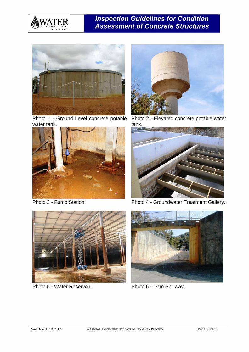
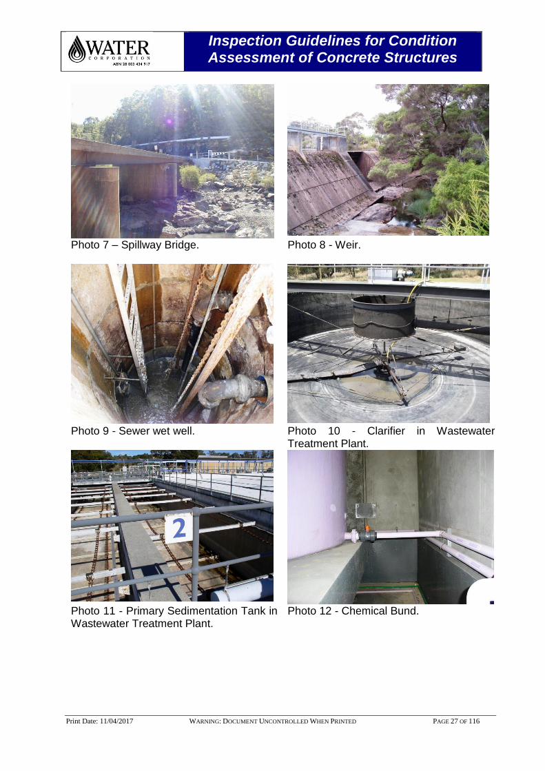
The purpose of this document is to establish the guidelines for the Condition Assessment (CA) of concrete structures in both potable water and wastewater environment in the Water Corporation [Refer: Photos 1-12]. The guideline will assist the Inspection Service Providers (ISP’s)/Region/Alliance/OAM to conduct objective, consistent and reproducible asset condition ratings and Remaining Service Life (RSL)] [3]. The condition assessment in this document is based on the relevant AS/NZS, ASTM, BS, NACE standards, Standard Operating Procedures (SOP’s), Water Corporation design standards and in-house concrete structures inspection experience. The guideline clarifies the qualification(s), responsibilities, accountabilities, inspection data capturing techniques, interpretation and reporting format for ISP’s. The guideline will also aid the ISP’s to prepare and deliver the inspection findings to an appropriate format so that Asset Management Branch (AMB) can verify the RSL of the asset and subsequently prioritise the asset renewal based on the informed Asset Risk Assessment (ARA) and Concrete Structures Remaining Service Life (CRSL) Tool. In accordance with the Water Corporation Design Standard DS 61, the design life of concrete asset is minimum 100 years. If the design life differs, then subsequent management strategy will be developed to achieve the intended service life by AMB. For concrete structures condition assessment methodology, references shall be made to Aqua Doc. 11573252 [4]. For steel structural elements condition assessment guideline, references shall be made to Aqua Doc. 11051170 [5].
Inspection Guidelines for Condition Assessment of Concrete Structures
Print Date: 11/04/2017 WARNING: DOCUMENT UNCONTROLLED WHEN PRINTED PAGE 26 OF 116
Photo 1 - Ground Level concrete potable water tank.
Photo 2 - Elevated concrete potable water tank.
Photo 3 - Pump Station. Photo 4 - Groundwater Treatment Gallery.
Photo 5 - Water Reservoir. Photo 6 - Dam Spillway.
Inspection Guidelines for Condition Assessment of Concrete Structures
Print Date: 11/04/2017 WARNING: DOCUMENT UNCONTROLLED WHEN PRINTED PAGE 27 OF 116
Photo 7 – Spillway Bridge. Photo 8 - Weir.
Photo 9 - Sewer wet well. Photo 10 - Clarifier in Wastewater
Treatment Plant.
Photo 11 - Primary Sedimentation Tank in Wastewater Treatment Plant.
Photo 12 - Chemical Bund.
Inspection Guidelines for Condition Assessment of Concrete Structures
Print Date: 11/04/2017 WARNING: DOCUMENT UNCONTROLLED WHEN PRINTED PAGE 28 OF 116
2.0 CONCRETE PRE-INSPECTION PREPARATION
2.1 Inspection Requirements
Prior to conducting inspection, the Operator/Inspector/Diver (collectively “Inspector”) must fully understand the condition assessment and data capture process. The inspectors must also be familiar with the criterion (condition rating & priority repair works) used to assess the tank condition. Any Inspector undertaking on-site condition assessments shall be appropriately qualified and experienced for the task. This is applicable to in-house personnel or external ISP’s. The data collection and reports will provide valuable information not only on the asset condition but also assists in understanding the risk and current performance of the concrete structures. The inspector should ensure that the assessment is complete with appropriate levels of detail for each relevant component of the structures with a rated condition. The corrosion measurements and assessments must be made with high degree of accuracy. The data collected should adhere to the criteria provided so that there is consistency between surveys. The various levels of inspection checklist are included in the Appendices of this document. For internal ISP’s Level 1, Level 2 work pack (inspection checklist template & condition rating) can be downloaded from AMB website http://waternet.watercorporation.com.au/a/AMB/index.cfm. The external ISP’s can obtain the inspection work pack from the Asset Manager or Responsible Person for the inspection activities. After completion of inspections, the report should be sent to the Asset Manager or Responsible Person in Renewals Planning. The inspection data will then be updated and analysed in the Concrete Structures Remaining Service Life (CRSL) Tool database [6]. Inspection reports should be saved into the ACA program for future reference. All inspecting personnel shall hold appropriate site safety inductions both general and site specific. If the asset is deemed to be confined space and/or working at heights, then appropriate valid certification shall be possessed by the in-house personnel and ISP’s. The certificates shall be available to the Water Corporation for verification at least 10 working days prior to the inspection.
Inspection Guidelines for Condition Assessment of Concrete Structures
Print Date: 11/04/2017 WARNING: DOCUMENT UNCONTROLLED WHEN PRINTED PAGE 29 OF 116
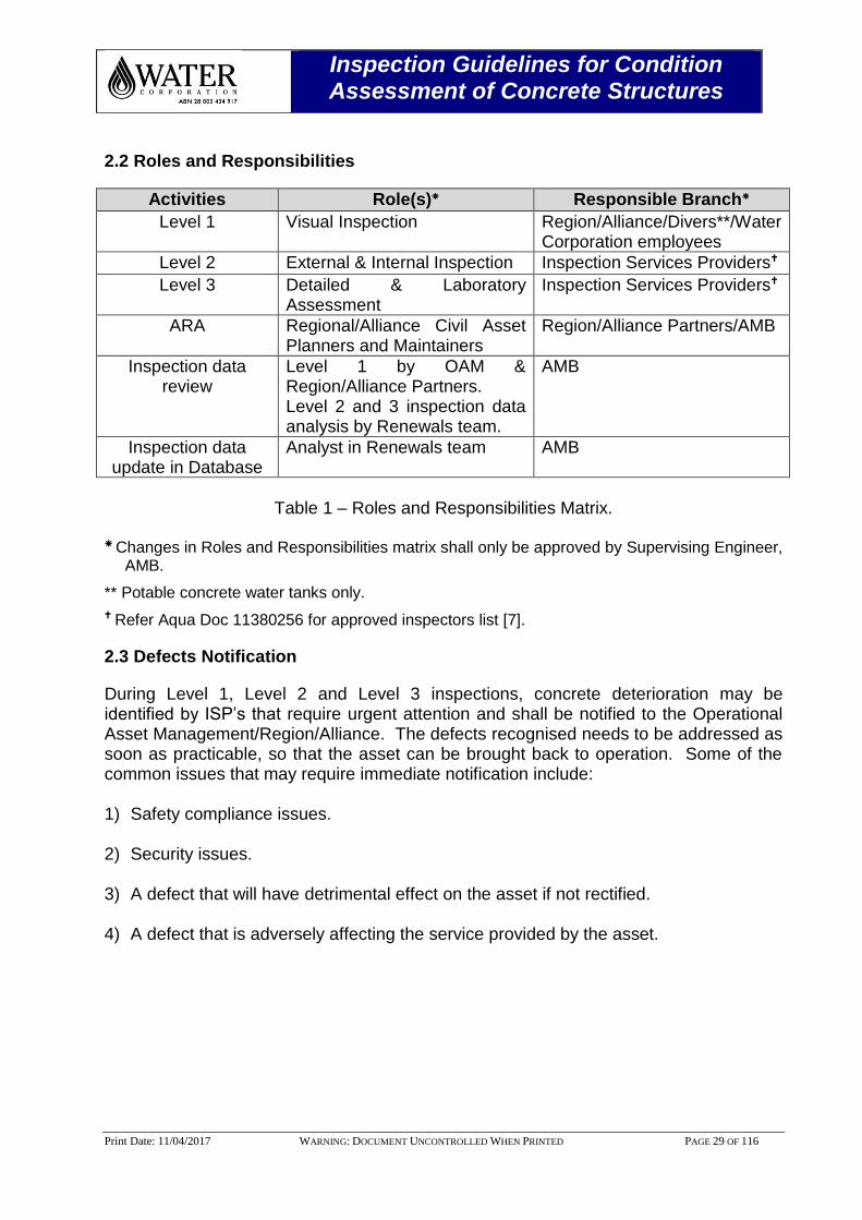
2.2 Roles and Responsibilities
Activities Role(s) Responsible Branch
Level 1 Visual Inspection Region/Alliance/Divers**/Water Corporation employees
Level 2 External & Internal Inspection Inspection Services Providers
Level 3 Detailed & Laboratory Assessment
Inspection Services Providers
ARA Regional/Alliance Civil Asset Planners and Maintainers
Region/Alliance Partners/AMB
Inspection data review
Level 1 by OAM & Region/Alliance Partners. Level 2 and 3 inspection data analysis by Renewals team.
AMB
Inspection data update in Database
Analyst in Renewals team AMB
Table 1 – Roles and Responsibilities Matrix.
Changes in Roles and Responsibilities matrix shall only be approved by Supervising Engineer,
AMB.
** Potable concrete water tanks only.
Refer Aqua Doc 11380256 for approved inspectors list [7].
2.3 Defects Notification
During Level 1, Level 2 and Level 3 inspections, concrete deterioration may be identified by ISP’s that require urgent attention and shall be notified to the Operational Asset Management/Region/Alliance. The defects recognised needs to be addressed as soon as practicable, so that the asset can be brought back to operation. Some of the common issues that may require immediate notification include: 1) Safety compliance issues. 2) Security issues. 3) A defect that will have detrimental effect on the asset if not rectified. 4) A defect that is adversely affecting the service provided by the asset.
Inspection Guidelines for Condition Assessment of Concrete Structures
Print Date: 11/04/2017 WARNING: DOCUMENT UNCONTROLLED WHEN PRINTED PAGE 30 OF 116
2.4 Inspection Data Interpretation
Persons responsible for identifying and recording defects shall hold a suitable qualification for various levels of inspection and is discussed in Section 3.0. AMB is responsible for analysing the inspection data (Level 2 & Level 3) provided by ISP’s and shall be competent in the following: 1) Interpreting information contained in the inspection reports. 2) Identifying and coding of defects and other features. 3) Verifying the inspection scoring/grading system. 4) Recording the inspection scoring/grading system in CRSL tool. 5) Recognising concrete deterioration mechanism and the likely parameter contributing
to the defects. 6) Recognising inspection videos and camera inspection quality.
Inspection Guidelines for Condition Assessment of Concrete Structures
Print Date: 11/04/2017 WARNING: DOCUMENT UNCONTROLLED WHEN PRINTED PAGE 31 OF 116
3.0 LEVELS OF CONCRETE INSPECTION
AMB propose on all the Water Corporation concrete structures that the condition assessment is undertaken at three levels:
3.1 Level 1 – Routine Operation and Maintenance Inspection
Level 1 inspection will assist in assessment of the overall safety and performance of the concrete structure. A Level 1 inspection can be carried out by Water Corporation employees including treatment plant operators, chemical dosing plant supervisors, asset maintainers, asset planners, service delivery representative and diving contractors. Relevant inspection data is captured as part of the on-going operation and maintenance process. If concrete deterioration is a threat to the structural integrity of the asset, then an Asset Deficiency Report (ADR) must be created by the asset inspector. The Asset Manager or responsible person must also use the Asset Risk Assessment (ARA) system and verify the likelihood and consequence of failure i.e. risk rating for the concrete structure. Renewals Planning, AMB will endorse the risk assessment and also use the appropriate Concrete Remaining Service Life (CRSL) tool to calculate the indicative Remaining Service Life (RSL) of the structure from the Level 1 assessment. Where the indicative RSL is calculated to be within 5 years, a Level 2 inspection may be initiated and planned in the appropriate year for condition assessment. Level 1 inspection is carried out as part of routine operational budgets and activities. Refer Appendix B inspection checklist for Level 1 inspection by Water Corporation employees and external Inspection Service Providers (ISP’s).
3.2 Divers Inspection – Potable Water Concrete Tanks & Reservoir
3.2.1 Tank Cleaning and Standard Inspection by Divers
The divers shall vacuum all the sediment and ensure the tank floor is thoroughly cleaned. Once cleaned, a “Standard Inspection” should be carried out by taking photos of key components. The diver’s standard inspection, (i.e. after tank cleaning), shall capture typically 60 to 100 photographs. The photos should be labelled with the name of the tank component followed by the numbering sequence i.e. a photo should be called “Wall to Floor Joint 2”. In addition, short video clips shall be captured on the hand held camera with no voice commentary. If there are problems found within the asset, a greater volume of photos should be taken to capture the problem.
Inspection Guidelines for Condition Assessment of Concrete Structures
Print Date: 11/04/2017 WARNING: DOCUMENT UNCONTROLLED WHEN PRINTED PAGE 32 OF 116
3.2.2 Tank Cleaning - Divers Qualifications
For Diving Inspector, the minimum level of qualification to carry out inspection of Water Corporation tanks shall be a valid Part 2 - Surface Supply Breathing Apparatus (SSBA) accredited by ADAS. The qualification for Diving Supervisor is a valid Part 1 - Occupational Self-Contained Underwater Breathing Apparatus (SCUBA) to 30 metres. It is intended to establish occupational SCUBA qualification for engineering inspection diving. The qualification limits the diver to using hand tools or conducting inspections. The Part 1 certified diver cannot operate surface controlled power tools, or dive in operations where the use of overhead lifting or other similar activities is required.
3.2.3 Civil Inspection by Divers
The current format of a “Civil Inspection” is where the diver completes the same process outlined above but with more detail. It is recommended that more photos are taken on each component and problematic areas. Photos should not be individually renamed, but are filed in named folders, so the Corporation can get a folder called “walls” with a bundle of un-named photos of the walls. The divers shall produce interactive video typically an hour or two long and record every part of the asset in detail with commentary by the diver and supervisor. The video record shall include the entire inspection. The diver shall submit 3 copies of the tank inspection video and inspection report in electronic format able to read by the Corporation including the following defects or features: 1. Deformed or broken appurtenances. 2. Multiple failed components. 3. Continuous defects or features such as defect coating, corrosion on the floor, wall,
weld joint corrosion etc. 4. Significant erosion, corrosion or surface damage. 5. Defective steps, ladders, platforms, inlet pipe, columns, scour pipe, overflow pipe
etc.
6. A minimum of one image should be a direct view showing the defect feature in the context of the tank. Images from zoomed, titled or panned camera are supplementary and should not be used alone.
7. Lighting and focus should be adjusted to ensure a quality image. If the feature is
not identifiable it may be useful to capture several images from different positions. 8. The minimum resolution for the photographs shall be 4500 x 3000 pixel dimensions
and the file size for individual photos shall be 5 MB or higher.

Inspection Guidelines for Condition Assessment of Concrete Structures
Print Date: 11/04/2017 WARNING: DOCUMENT UNCONTROLLED WHEN PRINTED PAGE 33 OF 116
Note: During civil inspection, Diver shall use appropriate and approved Ultrasonic
Thickness (UT) and localised metal loss (pit depth) gauges to record remaining steel thickness readings of the steel columns and any problem areas of the tank.
3.2.4 Divers Qualifications
For Civil Inspection, the divers shall possess valid CSWIP 3.1U - NDT Inspection certification issued by The Welding Institute (TWI) [8]. In addition, the Divers shall also attend one-day corrosion awareness course “Introduction to Corrosion” conducted by Australasian Corrosion Association (ACA) [9].
3.2.5 Divers Inspection Report
The inspection report shall consist of structural elements nominated in the scope of work. The report shall be computerised version detailing the observations including location and characteristics of reportable features including defects and features of interest. The supervisor shall fill out a Microsoft Excel® template with information based on the diver’s comments. Refer Appendix B for the standard inspection checklist template.
Inspection Guidelines for Condition Assessment of Concrete Structures
Print Date: 11/04/2017 WARNING: DOCUMENT UNCONTROLLED WHEN PRINTED PAGE 34 OF 116
3.2.6 Divers Condition Rating Outcome & AMB Interpretation
Currently, the diver’s asset condition rating follows 5 point system. For the future inspections, Divers shall follow Water Corporation AMB’s point grading system recommended by CRSL model and is shown in Table 2.
Divers – Asset Condition
Rating
Equivalent AMB - Condition
Rating
Asset Condition Rating Outcome
1 1 Excellent condition: No defect/No corrosion.
2 3 Good condition: Some minor wear but tank component is structurally sound and free of major defects.
3 5 Fair condition: Tank component has some wear and tear, corrosion, but is adequately functional
4 7 Poor condition: Tank component has significant wear, corrosion or defects.
5 10 Very poor condition: Tank component is likely to fail and requires attention as soon as practical.
Table 2 - Divers and equivalent AMB’s condition rating.
Note: AMB will determine effective Remaining Service Life (RSL) from Divers
inspection results in CRSL tool and will update the concrete structures inspection database [Refer: AquaDoc No. 11795743] [10].
3.2.7 Inspection by Others - Water Corporation Personnel
Before carrying out visual inspection, the Water Corporation employees shall complete and possess approved permits including Job-Safety Analysis (JSA), Job Safety and Environment Analysis (JSEA) and site-safe inductions. If the Corporation employees carry out roof inspection then they shall also possess valid working at heights certificates. The inspection finding shall be reported to OAM/Regional Alliance/AMB. If the defects deemed to be significant, then OAM will conduct an ARA. AMB will review the ARA with the asset owner and further actions will be discussed.
Inspection Guidelines for Condition Assessment of Concrete Structures
Print Date: 11/04/2017 WARNING: DOCUMENT UNCONTROLLED WHEN PRINTED PAGE 35 OF 116
3.3 Condition Rating Interpretation
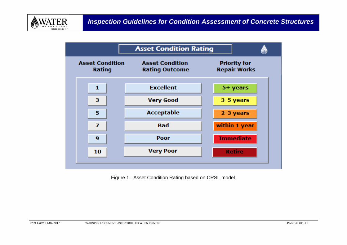
During Level 1 and Level 2 inspections, some of the steel and concrete structures should be evaluated and rated. The main purpose of rating the concrete structure is to evaluate the condition in an objective approach and its effective RSL. The assessment will assist further decision-making about the Level of Service (LOS) provided by the concrete structures. It should be noted that the rate of condition degradation usually increases over time. By means of rating, appropriate remedial measures can be prioritised. For example, if the rating is 7, then 70% physical life is consumed, then the structure should be remediated within 1 year to achieve the LOS. The condition rating assessment methodology for concrete structures is based on comparison to standard charts, photographs and engineering calculation etc. A series of charts published by the AS/NZS engineering standards, Standard Practices (SP) published by NACE, ASTM standard is used to make an informed decision on the condition rating of the asset. For the condition assessment of concrete structures, AMB utilises CRSL tool [Refer: Figure 1]. The condition rating is based on 1 to 10 rating systems are aligned to Institute of Public Works Engineering Australia and the outcome is summarised as below [11]. Excellent Physical condition - Observable deterioration is none. Less than
10%.physical life is consumed. Very Good Physical condition - Observable deterioration is insignificant. No
adverse service reports. 30% physical life is consumed. Acceptable Physical condition - Observation and/or testing indicate that the
asset is meeting all service requirements. Sound Physical condition. Minor deterioration/minor defects observed. 50% physical life is consumed.
Bad Physical condition - Moderate deterioration evident. Minor components
or isolated sections of the asset need replacement or repair now but not affecting short term structural integrity. 70% physical life is consumed.
Poor Physical condition - Serious/Significant deterioration evident and
affecting structural integrity. Asset is now moving into zone of failure. 90% physical life is consumed.
Very Poor Physical condition - Failed or failure imminent. Immediate need
to replace most or the entire asset. 100% physical life is consumed.
Inspection Guidelines for Condition Assessment of Concrete Structures
Print Date: 11/04/2017 WARNING: DOCUMENT UNCONTROLLED WHEN PRINTED PAGE 36 OF 116
Figure 1– Asset Condition Rating based on CRSL model.
Inspection Guidelines for Condition Assessment of Concrete Structures
Print Date: 11/04/2017 WARNING: DOCUMENT UNCONTROLLED WHEN PRINTED PAGE 37 OF 116
3.4 Level 2 - Formalised Inspection
Level 2 is a planned inspection after an ARA on the concrete structure has been endorsed by AMB. The condition rating from the Level 2 inspection will be captured into the CRSL whereby the RSL of the concrete structure will be ascertained. A Level 2 inspection may be used to identify remedial action required to extend life to prevent premature failure of a concrete structure. On an annual basis, the Renewals Planning team will carry out an evaluation of all concrete structures using the relevant CRSL tool and where the theoretical RSL for the worst defect is shown to be between 3 to 5 years and/or high/extreme risk, a Level 2 inspection may be triggered. For all assets requiring a Level 2 inspection, an ARA must be completed by the Renewals Planning team of AMB and approved by the Asset Manager or Responsible Person. Level 2 inspection is carried out as part of the planned condition assessment capital program. Level 2 inspections are undertaken to ensure the following objectives:
Ensure that the concrete structure continues to operate to the required level without operational problems;
To record the current asset condition i.e. corrosion deterioration, general wear and tear;
To assess and determine maintenance requirements such as replacing cathodic protection sacrificial anodes, nuts and bolts etc.;
To forecast future technical problems;
Confirm if the previous repairs works that are carried out functioning properly or new repair methodologies are required to remediate the problem.
Determine the RSL of the concrete structures.
Level 2 inspection findings will be sent to AMB for further analysis. In Level 2, AMB will then carry out ARA and infer the effective remaining life using CRSL tool [Refer: Aqua Doc. 11795696] [12]. Level 2 inspection is carried out as part of the planned condition assessment capital program. On an annual basis, the Renewals Planning team will carry out an evaluation of concrete structures using CRSL and where the theoretical RSL is shown to be between 3 to 5 years, a Level 2 inspection may be triggered. For all assets requiring a Level 2 inspection, an ARA must be completed by the Renewals Planning team and approved by the OAM. Refer Appendix C for the Level 2 inspection template.
Inspection Guidelines for Condition Assessment of Concrete Structures
Print Date: 11/04/2017 WARNING: DOCUMENT UNCONTROLLED WHEN PRINTED PAGE 38 OF 116
3.4.1 Calibration of Inspection Gauges
Inspection gauges shall be calibrated in accordance to the manufacturers recommended practices and interval. Calibration certificates shall be available to the Water Corporation prior to the inspection.
3.4.2 Qualification of Level 2 Inspectors
The formalised concrete structure inspection shall only be carried out by qualified and experienced inspectors [7]. This is to ensure quality and reliability of inspection and data obtained for further analysis. Under no circumstances, non-qualified ISP’s shall be engaged for Level 2 inspection. The Level 2 inspectors shall prove to Water Corporation that they have enough experience in tank inspection and shall submit any one of the certification gained from Australasian Corrosion Association and/or by Australasian Concrete Repair Association (ACRA):
Corrosion Technician certification;
Corrosion Technologist certification;
Corrosion and Protection of Reinforced Concrete;
Concrete Repair & Protection Course.
For coating inspection, the inspector shall possess ACA Coating Inspector (or) National Association of Corrosion Engineers (NACE) minimum NACE CIP Level II Coating Inspector. Where the RSL is calculated to be within 3 years, a Level 3 assessment may be initiated by the Renewals Planning team where it is deemed cost effective and/or further data is required to determine the requirement for intervention.
3.5 Level 3 – Detailed Investigation
Level 3 inspections will be carried out, where the ARA is very high and/or Level 2 inspection showed that the asset is nearing the end of its physical life. AMB will recommend Level 3 inspection based on the asset Physical Life and Level of Service (LOS), Refer Aqua Doc. No. 11833402 [13]. Where the RSL is calculated to be within 3 years and/or high/extreme risk, a Level 3 assessment may be initiated by the Renewals Planning team of AMB where it is deemed cost effective and/or further data is required to determine the need for intervention. Level 3 inspection is carried out as part of the planned condition assessment capital program. The guideline below describes how the Corporation is undertaking condition assessments on its concrete structure assets. The methodology below describes how the Corporation is undertaking condition assessments on its concrete structural assets. An overview of the process is depicted in Figure 2. Refer Appendix D for Level 3 inspection template.
Inspection Guidelines for Condition Assessment of Concrete Structures
Print Date: 11/04/2017 WARNING: DOCUMENT UNCONTROLLED WHEN PRINTED PAGE 39 OF 116
3.5.1 Aim of Level 3 Inspection
Level 3 inspections may be required due to concerns over concrete structural safety, complexity of remediation works recommended during Level 2 inspection. The main objectives are:
To establish and record the current physical and functional condition of a structure;
To identify likely future problems and the approximate timing of those problems;
To determine and measure the type and extent of the maintenance needs;
To establish a history of material performance; and
To provide feedback to design, construction and maintenance engineers.
3.5.2 Scope of a Level 3 Inspection
The scope of Level 3 inspection will be defined in the investigation brief. The extent may be very broad and will depend on the purpose of the inspection. For example, the purpose may be testing of material condition to establish a reference from which to measure and monitor deterioration (establishing a benchmark), or to establish extent of maintenance works, (defect identification) or to provide information on components that are not accessible during a Level 2 Inspection.
3.5.3 Outputs of a Level 3 Inspection
The outputs of a Level 3 Inspection include:
Summary of purpose and scope
Description of test plan and test methods utilised
Diagrammatic and photographic information on test locations
Test results with analysis and interpretation where required
Photographic records of all deteriorated materials observed on site.
Recommended maintenance options including intervention schedule for use by the AMB.
Recommended repair materials
Quantification of the extent of repairs suitable for comparison of alternatives and also for preliminary budgetary purposes.
Inspection Guidelines for Condition Assessment of Concrete Structures
Print Date: 11/04/2017 WARNING: DOCUMENT UNCONTROLLED WHEN PRINTED PAGE 40 OF 116
3.5.4 Qualification of Level 3 Inspectors
In general, the Contractor shall be very knowledgeable in various disciplines including Concrete, Corrosion, Materials Science and Structural Engineering. The Contractor should be very thorough in non-destructive testing methods of concrete structures as well as various aspects of construction materials including design, construction, rehabilitation and maintenance. The Level 3 inspector’s shall possess an engineering associate or degree in relevant discipline.
Inspection Guidelines for Condition Assessment of Concrete Structures
Print Date: 11/04/2017 WARNING: DOCUMENT UNCONTROLLED WHEN PRINTED PAGE 41 OF 116
Routine Maintenance
(e. g. Tank cleaning program)
Level 1 - Routine Operation and
Maintenance Inspection
Level 2 - Formalised Asset Inspection (Intrusive Inspection)
(or)
Level 3 - Detailed Condition Assessment (Destructive Testing)
Report on:
1) Asset Condition Rating
2) Remedial action & Recommendation
3) Recommend inspection interval
Report on:
1) Asset Condition Rating
2) Remedial action & Recommendation
3) Recommend inspection interval
- Divers
- Civil Consultant
- Plant Operators
- Asset Planner
- Other Water Corporation Employee
Scoping of Work
In accordance with concrete structure inspection guideline,
decide on whether Level 2 or Level 3 required during
scoping phases
- Carried out by AMB/Region/Alliance
Inspection can be carried out by
Review Level 1
Inspection Report
Asset Condition Assessment
(ACA) System in SAP
Maintenance Program
Defects requiring
further investigation
No
Carry out ARA
Driven by Level 1 Inspection
- ARA by OAM
Carryout Assessment (AMB):
- Decision Support Tool (e.g. CRSL) and
- Review ARA with Asset Owner
Asset Condition
Assessment [ACA]
Request
Yes
High Risk identified
by CRSL Tool
- Carried out by AMB
Defects Repairs
Required Asset Deficiency
Report [ADR]
Maintenance
Program
Yes
Asset Management
Branch (AMB)
Concrete Remaining
Service Life (CRSL) Tool
Operational Asset
Management (OAM) to Review
Inspection Report & upload in
ACA Database
Online Appropriation
Request [OAR]
Replace Asset
Upload report to
ACA System in
SAP
Update CRSL Tool
with asset condition
data
Remaining Service
Life [RSL]
Review ARA
Renewals
RequiredYesNo
Asset Management Branch (AMB)
Operational Asset Management (OAM)
AMB/Region/Alliance
Optioneering
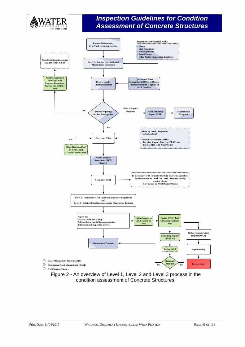
Figure 2 - An overview of Level 1, Level 2 and Level 3 process in the
condition assessment of Concrete Structures.
Inspection Guidelines for Condition Assessment of Concrete Structures
Print Date: 11/04/2017 WARNING: DOCUMENT UNCONTROLLED WHEN PRINTED PAGE 42 OF 116
4.0 EXPOSURE ENVIRONMENT FOR POTABLE WATER & WASTE WATER ASSETS
4.1 Exposure Environment for Water Corporation Assets
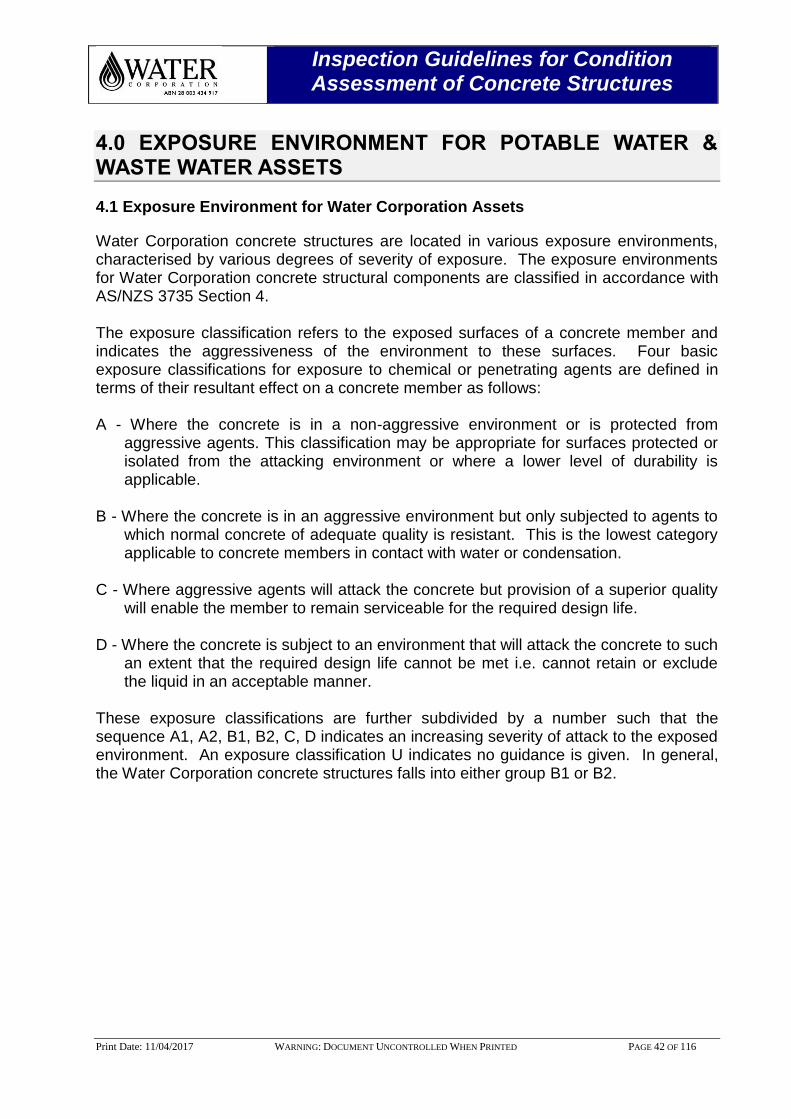
Water Corporation concrete structures are located in various exposure environments, characterised by various degrees of severity of exposure. The exposure environments for Water Corporation concrete structural components are classified in accordance with AS/NZS 3735 Section 4. The exposure classification refers to the exposed surfaces of a concrete member and indicates the aggressiveness of the environment to these surfaces. Four basic exposure classifications for exposure to chemical or penetrating agents are defined in terms of their resultant effect on a concrete member as follows: A - Where the concrete is in a non-aggressive environment or is protected from
aggressive agents. This classification may be appropriate for surfaces protected or isolated from the attacking environment or where a lower level of durability is applicable.
B - Where the concrete is in an aggressive environment but only subjected to agents to
which normal concrete of adequate quality is resistant. This is the lowest category applicable to concrete members in contact with water or condensation.
C - Where aggressive agents will attack the concrete but provision of a superior quality
will enable the member to remain serviceable for the required design life. D - Where the concrete is subject to an environment that will attack the concrete to such
an extent that the required design life cannot be met i.e. cannot retain or exclude the liquid in an acceptable manner.
These exposure classifications are further subdivided by a number such that the sequence A1, A2, B1, B2, C, D indicates an increasing severity of attack to the exposed environment. An exposure classification U indicates no guidance is given. In general, the Water Corporation concrete structures falls into either group B1 or B2.
Inspection Guidelines for Condition Assessment of Concrete Structures
Print Date: 11/04/2017 WARNING: DOCUMENT UNCONTROLLED WHEN PRINTED PAGE 43 OF 116
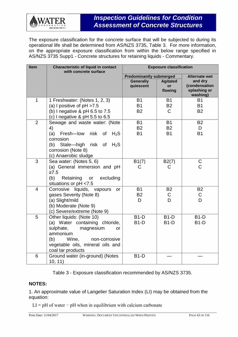
The exposure classification for the concrete surface that will be subjected to during its operational life shall be determined from AS/NZS 3735, Table 3. For more information, on the appropriate exposure classification from within the below range specified in AS/NZS 3735 Supp1 - Concrete structures for retaining liquids - Commentary. Item Characteristic of liquid in contact
with concrete surface Exposure classification
Predominantly submerged Alternate wet and dry
(condensation splashing or
washing)
Generally quiescent
Agitated or
flowing
1 1 Freshwater: (Notes 1, 2, 3) (a) I positive of pH >7.5 (b) I negative & pH 6.5 to 7.5 (c) I negative & pH 5.5 to 6.5
B1 B1 B2
B1 B2 C
B1 B1 B2
2 Sewage and waste water: (Note 4) (a) Fresh—low risk of H2S corrosion (b) Stale—high risk of H2S corrosion (Note 8) (c) Anaerobic sludge
B1 B2 B1
B1 B2 B1
B2 D B1
3 Sea water: (Notes 5, 6) (a) General immersion and pH ≥7.5 (b) Retaining or excluding situations or pH <7.5
B1(7) C
B2(7) C
C C
4 Corrosive liquids, vapours or gases Severity (Note 8) (a) Slight/mild (b) Moderate (Note 9) (c) Severe/extreme (Note 9)
B1 B2 D
B2 C D
B2 C D
5 Other liquids: (Note 10) (a) Water containing chloride, sulphate, magnesium or ammonium (b) Wine, non-corrosive vegetable oils, mineral oils and coal tar products
B1-D B1-D
B1-D B1-D
B1-D B1-D
6 Ground water (in-ground) (Notes 10, 11)
B1-D — —
Table 3 - Exposure classification recommended by AS/NZS 3735.
NOTES:
1. An approximate value of Langelier Saturation Index (LI) may be obtained from the equation:
LI = pH of water − pH when in equilibrium with calcium carbonate
Inspection Guidelines for Condition Assessment of Concrete Structures
Print Date: 11/04/2017 WARNING: DOCUMENT UNCONTROLLED WHEN PRINTED PAGE 44 OF 116
= pH −12.0 + log10 [2.5 × Ca2+
(mg/L) × total alkalinity (as CaCO3 mg/L)].
(A negative value for LI means the water has a demand for CaCO3).
2. For lower pH values see Item 4.
3. For water containing significant quantities of aggressive dissolved materials see Item 5(b).
4. Industrial sewage and waste water may contain aggressive chemicals. The designer shall refer to other liquids as given in Table 4.1 (see also AS 3735 Supp1).
5. The use of galvanized or epoxy-coated reinforcement or a waterproofing agent should be considered. Details are given in AS 3735 Supp1.
6. The use of sulphate-resisting cement is discouraged.
7. Only applicable for submergence greater than 1 m below low water ordinary spring tide.
8. Typical examples of severities are given in AS 3735 Supp1.
9. The use of calcareous aggregate should be considered. Details are specified in AS 3735 Supp1.
10. Guidance on the selection of an appropriate exposure classification from within the range indicated is specified in AS 3735 Supp1.
11. For members in contact with extracted ground water see Item 1 or 5.
Inspection Guidelines for Condition Assessment of Concrete Structures
Print Date: 11/04/2017 WARNING: DOCUMENT UNCONTROLLED WHEN PRINTED PAGE 45 OF 116
5.0 REBAR CORROSION & CONCRETE DETERIORATION MECHANISMS
5.1 Rebar Corrosion - Mechanism
Corrosion is an electrochemical process involving the flow of charges (electrons and ions). The passivating film provided to the steel by the highly alkaline cement is destabilised when contacted with aggressive agents such as chloride. This process is called a half-cell oxidation reaction, or the anodic reaction, and is represented as:
2Fe → 2Fe2+
+ 4e-
[1]
The electrons remain in the reinforcing bar and flow to sites called cathodes, where they combine with water and oxygen in the concrete. The reaction at the cathode is called a reduction reaction.
2H2O + O2 + 4e- → 4OH
- [2]
To maintain electrical neutrality, the ferrous ions migrate through the concrete pore water to these cathodic sites where they combine to form iron hydroxides, or rust:
2Fe2+
+ 4OH- → 2Fe(OH)2
[3]
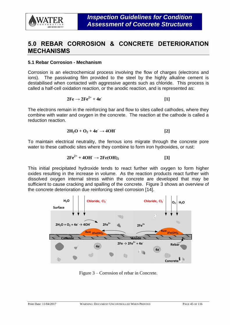
This initial precipitated hydroxide tends to react further with oxygen to form higher oxides resulting in the increase in volume. As the reaction products react further with dissolved oxygen internal stress within the concrete are developed that may be sufficient to cause cracking and spalling of the concrete. Figure 3 shows an overview of the concrete deterioration due reinforcing steel corrosion [14].
Iron
4e-
Concrete
2H2O + O2 + 4e- → 4OH-2Fe2+2Fe2+
Anode
2Fe → 2Fe2+ + 4e-
4e-
Cathode
2Fe(OH)2Rust
2Fe(OH)2Rust
H2O H2O
Surface
O2 Chloride, Cl2- Chloride, Cl2
-
Rebar
Figure 3 – Corrosion of rebar in Concrete.

Inspection Guidelines for Condition Assessment of Concrete Structures
Print Date: 11/04/2017 WARNING: DOCUMENT UNCONTROLLED WHEN PRINTED PAGE 46 OF 116
Corrosion of reinforcement is mostly caused by either carbonation of the concrete or by contamination with chlorides or both [15, 16].
A small amount of loss of reinforcement section can produce copious rust product because of its expansive nature. Therefore extreme care should be taken to ensure that the loss of rebar section is not estimated from the thickness of corrosion product. Estimates of loss or rebar section should be made by cleaning of the rebar and measuring its diameter. The corrosion on the rebar is classified as follows: G = General and L = Localised [Refer: Photos 13 & 14].
Photo 13 - Generalised chloride induced rebar corrosion. [Photo Courtesy: http://civil-
engg-world.blogspot.com.au/2011/03/corrosion-induced-by-chloridesrcc.html].
Photo 14 - Localised chloride induced rebar corrosion. [Photo Courtesy: http://www.
en.wikipedia.org/wiki/Concrete_degradation].
5.2 Rebar Corrosion Classification
5.2.1 Classification 1
Rebar appears passive. There is no observable corrosion, but the rebar may have mill scale on the surface. In some instances, surface “lime” deposits from the surrounding concrete may also be seen on the rebar. Neither section loss of the rebar, nor any signs of pitting attack on the profile of the ribs [Refer: Photo 15].
Photo 15 - Classification 1, Mill Scale on the rebar.
5.2.2 Classification 2
Rebar is largely passive. There is a slight surface corrosion deposits of orange and brown corrosion products appearing in discrete “blotches”, particularly at the intersection points of the ribs. These corrosion products are easily removed by scraping [Refer: Photo 16].

Inspection Guidelines for Condition Assessment of Concrete Structures
Print Date: 11/04/2017 WARNING: DOCUMENT UNCONTROLLED WHEN PRINTED PAGE 47 OF 116
Photo 16 - Classification 2, Discrete blotches of corrosion products.
5.2.3 Classification 3G
Rebar has a thin corrosion scale on its surface, mainly red or reddish brown in colour. There is no noticeable loss in rebar section, although slight damage to the profile of the ribs may have taken place. There will be no cracking of the concrete associated with the formation of these corrosion products [Refer: Photo 17].
Photo 17 - Classification 3G. No noticeable loss in bar section.
5.2.4 Classification 3L
Rebar has a form of localised attack, which should be distinguished from the general type of attack. It leaves the bar with large areas (up to 75%) which could be in Classification 1 or 2, but the remainder of the rebar having undergone a moderately severe attack. There may also have been cracking of the surrounding concrete, due to the formation of expansive corrosion products on the surface of the rebar [Refer: Photo 18].
Photo 18 - Classification 3L. Majority of the surface covered with heavy dark brown rust.
5.2.5 Classification 4G
Rebar has the majority of its surface area covered with a heavy red or dark brown corrosion scale, up to a thickness of 1mm. The scale is very difficult to remove by simply scraping. There is a loss of rebar section associated with this level of corrosion, as much as 10% in places.
The rib patterns will have been seriously damaged and, in places, totally removed. The concrete surrounding the rebar may have been cracked by the formation of expansive corrosion products [Refer: Photo 19].
Photo 19 - Classification 4G. 50% of bar covered with rust & localised corrosion.
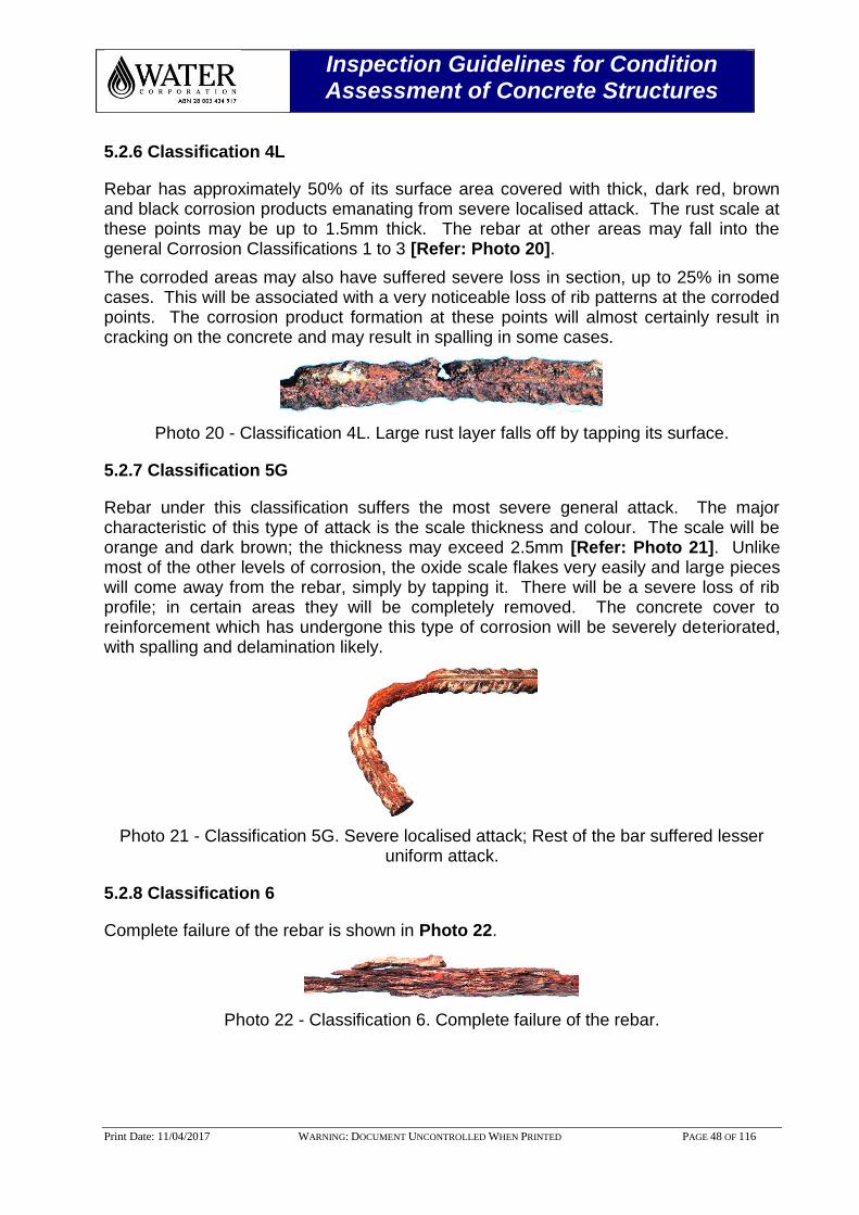
Inspection Guidelines for Condition Assessment of Concrete Structures
Print Date: 11/04/2017 WARNING: DOCUMENT UNCONTROLLED WHEN PRINTED PAGE 48 OF 116
5.2.6 Classification 4L
Rebar has approximately 50% of its surface area covered with thick, dark red, brown and black corrosion products emanating from severe localised attack. The rust scale at these points may be up to 1.5mm thick. The rebar at other areas may fall into the general Corrosion Classifications 1 to 3 [Refer: Photo 20].
The corroded areas may also have suffered severe loss in section, up to 25% in some cases. This will be associated with a very noticeable loss of rib patterns at the corroded points. The corrosion product formation at these points will almost certainly result in cracking on the concrete and may result in spalling in some cases.
Photo 20 - Classification 4L. Large rust layer falls off by tapping its surface.
5.2.7 Classification 5G
Rebar under this classification suffers the most severe general attack. The major characteristic of this type of attack is the scale thickness and colour. The scale will be orange and dark brown; the thickness may exceed 2.5mm [Refer: Photo 21]. Unlike most of the other levels of corrosion, the oxide scale flakes very easily and large pieces will come away from the rebar, simply by tapping it. There will be a severe loss of rib profile; in certain areas they will be completely removed. The concrete cover to reinforcement which has undergone this type of corrosion will be severely deteriorated, with spalling and delamination likely.
Photo 21 - Classification 5G. Severe localised attack; Rest of the bar suffered lesser uniform attack.
5.2.8 Classification 6
Complete failure of the rebar is shown in Photo 22.
Photo 22 - Classification 6. Complete failure of the rebar.
Inspection Guidelines for Condition Assessment of Concrete Structures
Print Date: 11/04/2017 WARNING: DOCUMENT UNCONTROLLED WHEN PRINTED PAGE 49 OF 116
5.3 General
The initiation and propagation of reinforcement corrosion in concrete structures can be influenced by both internal and external factors. These sources of deterioration depend on concrete properties and exposure conditions and, to a large extent, govern structural performance and remediation practices [17].
5.4 Internal Factors
The constituents of concrete may be key contributors to its internal degradation. Early age thermal restraint and shrinkage of concrete can cause cracking of the concrete, with a subsequent impact on the durability of the component and a potential for a reduction in RSL. The presence of undesired impurities in the concrete can also be a severe cause of deterioration, primarily due to chemical reaction of the constituents. Several common undesired impurities are discussed below.
5.4.1 Sulphate Content
The presence of excess sulphate from contaminated aggregate in freshly made concrete can cause severe degradation due to sulphate attack. The percentage by mass of acid-soluble SO4 to cement must not exceed 5.0%. Heat accelerated cured concrete, or concrete that has reached temperatures above 65-70° C during early cure, can also suffer from a form of internal sulphate attack called “Delayed Ettringite Formation” (DEF).
5.4.2 Delayed Ettringite Formation
DEF is a potential degradation mechanism that may occur in elevated temperature cured concrete structures. A reaction between sulphates and Calcium Hydroxide (Lime) to produce Calcium Sulphate (or Gypsum) may occur in concrete with a high concentration of sulphate. This consumption of lime lowers pH, allowing sulphate to react with destabilised aluminate minerals in the current paste to form an expansive mineral, Ettringite, which results in the breakdown of the cement paste. It is generally accepted that to effectively prevent concerns relating to DEF, the temperature of the concrete during curing has to be monitored and that for concrete temperatures of 70° C or less for cement type GP and 80° C or less for cement type Low Heat (LH) cement, the formation of DEF is not likely with normally available cements.

Inspection Guidelines for Condition Assessment of Concrete Structures
Print Date: 11/04/2017 WARNING: DOCUMENT UNCONTROLLED WHEN PRINTED PAGE 50 OF 116
5.4.3 Chloride Content
Aggregate contaminated with chlorides, or chlorides dissolved in chemical admixtures or mixing waters, can induce steel reinforcement corrosion. To avoid this, the mass of acid-soluble chloride ion per unit volume of concrete as placed shall not exceed 0.4 kg/m3.
5.4.4 Alkali Aggregate Reaction
Concrete can be damaged by an expansive, chemical reaction between active constituents of the aggregates and the alkalis (sodium and potassium as soluble hydroxides) in the cement; this process in known as alkali-aggregate reaction (AAR). The visible signs of AAR damage are characterised by a network of cracks known as map cracking [Refer: Photo 23]. The best technique for the identification of ASR is the examination of concrete in thin section, using a petrographic microscope. Alternatively, polished sections of concrete can be examined by optical microscopy and/or Scanning Electron Microscopy (SEM). A simple test using fluorescence of concrete samples treated with acidic uranyl acetate and exposed to UV-C light can often identify the presence of the gel product. ASR can cause internal stress and, ultimately, cracking by expansion when wet. ASR does not occur without the presence of water.
Photo 23 - Alkali–silica reaction affecting a concrete step barrier. [Photo courtesy: Federal Highway Administration, US Department of Transportation].
Inspection Guidelines for Condition Assessment of Concrete Structures
Print Date: 11/04/2017 WARNING: DOCUMENT UNCONTROLLED WHEN PRINTED PAGE 51 OF 116
5.5 External Factors
Concrete deterioration from external sources can occur in a variety of ways. The most important environmental causes of deterioration are the attack of sulphate, carbonation, chlorides, and the effects of stress, temperature and moisture.
5.5.1 Carbonation
Carbon dioxide (CO2) in the atmosphere diffuses through the empty pore of concrete and reacts with the hydration products, which is known as a carbonation process. The reduction in alkalinity will provide an environment conducive to the corrosion of the reinforcing steel should this carbonated layer reach the steel, and oxygen and moisture are present [18]. In chloride-free concrete, corrosion will not take place unless the pH drops below 11. Atmospheric carbon dioxide can penetrate concrete and react with calcium hydroxide Ca(OH) in the cement paste to form calcium carbonate (CaCO3) and this reaction reduces the pH of the concrete to around 9. Carbonation of concrete in the atmosphere is represented by the following simplified equation. This process is usually most pronounced in dry concrete.
Ca(OH)2 + CO2 → CaCO3 + H2O
When the carbonation front reaches the carbon steel reinforcement, the passive oxide on the steel surface becomes unstable, and corrosion of the steel commences. Corrosion rates are also aggravated by wet/dry cycling of weather.
5.5.2 Chloride Attack
The transportation of chloride ions into concrete involves diffusion, capillary suction, permeation and convective flow through the system and micro-cracking network, accompanied by physical adsorption and chemical binding. Chlorides penetrate the hardened concrete and break down the protective iron oxide layer on the steel reinforcement to initiate corrosion and the subsequent expansive disruption of the concrete matrix. The diffusion of chloride ions into concrete from external sources is dependent on concrete quality, cement type, cover, and exposure conditions. Periodic wet and dry exposure conditions accelerate corrosion rates severely [19].
5.5.3 Sulphate Attack
The deterioration of concrete exposed to sulphate is the result of the penetration of aggressive agents into the concrete and their chemical reaction with the calcium hydroxide in the cement matrix. The main reactions involved are Ettringite formation, gypsum formation and weakening of the calcium silicate hydrates in the binder. These chemical reactions can lead to expansion and cracking of concrete, and/or the loss of strength and elastic properties of concrete.
Inspection Guidelines for Condition Assessment of Concrete Structures
Print Date: 11/04/2017 WARNING: DOCUMENT UNCONTROLLED WHEN PRINTED PAGE 52 OF 116
5.5.4 Chemical Attack
Dissolution and disintegration of the concrete matrix due to the effect of harmful substances such as acids, soft water, grease and oils, which subsequently assist in the corrosion mechanism by reducing the depth and quality of the concrete cover to the reinforcing or prestressing steel.
5.5.5 Mechanical Damage
Mechanical damage may be caused by abrasion, erosion, vapours or gases, or impact damage.
5.5.6 Fire Damage
Fire damage can cause weakening of steelwork and can cause spalling of cover concrete. If the heat from a fire penetrates sufficiently deep into a reinforced concrete component, it can cause weakening of conventional reinforcement and even prestressing tendons.
5.5.7 Leaching
Loss of Ca(OH)2 from hardened cement paste, increasing the porosity, reduces the alkalinity of the concrete and therefore may initiate the corrosion mechanism. Where Ca(OH)2 is completely leached, the calcium silicate hydrates are destabilised by the resultant reduction in pH, and consequently the cement matrix becomes weak and friable.
5.5.8 Restrained movement
Cracking in concrete may occur due to internal stresses caused by restrained shrinkage, thermal contraction and expansion or other causes. This type of cracking may be identified by its location (e.g. along centreline of flat deck soffits, transverse cracks in kerbs) and the likelihood it is through the full thickness of the component.
5.6 Design and Construction Factors
In addition to external factors, consideration should be given to the way the structure was initially designed and constructed which may contribute to its current condition.
5.6.1 Poor Design
Inadequate structural design or lack of attention to relatively minor design details can lead to in-built deficiencies in structures. Typical errors are discussed below.
5.6.2 Inadequate structural design
This may result in cracking and/or spalling in areas which are subject to the highest stresses. To confirm inadequate design as a cause of damage, the capacity of the locations of damage should be compared to the types of stresses that should be present in the concrete. A detailed structural analysis may be required.

Inspection Guidelines for Condition Assessment of Concrete Structures
Print Date: 11/04/2017 WARNING: DOCUMENT UNCONTROLLED WHEN PRINTED PAGE 53 OF 116
Inadequate structural design can include use of an incorrect mix design to suit the exposure conditions.
5.6.3 Insufficient reinforcement cover
The concrete cover provides a physical barrier against the ingress of aggressive agents such as chlorides, carbon dioxide, oxygen and moisture. Under certain conditions, lack of cover will impair the ability of the concrete to provide protection from both physical and chemical deterioration, thus leading to corrosion of the steel reinforcement with subsequent cracking and spalling of the concrete.
5.6.4 Poor detailing
Poor detailing can result in the formation of defects and/or reduced durability. Examples of defects from poor detailing include corroding reinforcement from inadequate cover, honeycombed concrete at congested reinforcement, staining and corroding reinforcement from inadequate scupper projection below soffit, cracking from widely spaced reinforcement.
5.6.5 Poor Construction Practice
Failure to follow specified procedures and good practice, or outright carelessness during construction may lead to a number of adverse conditions. Poor workmanship that creates porous or permeable concrete, placement of concrete in high temperatures, plastic and restrained shrinkage and settlement of concrete may all lead to defects in the concrete and a reduction in durability. Typically, most of poor practices do not lead directly to failure or deterioration of concrete. Instead, they enhance the adverse impacts of other mechanisms. The following sections describe some of the most common poor practices.
5.6.6 Improper Curing
Symptoms of improperly cured concrete can include various types of cracking and surface disintegration. In extreme cases where poor curing leads to failure to achieve anticipated concrete strengths, structural cracking may occur.
5.6.7 Improper Concrete Consolidation
Unsatisfactory compaction of concrete may result in a variety of defects, the most common being “bug-holes”, honeycombing and cold joints. These defects can make it much easier for deterioration mechanisms to enter the concrete and initiate deterioration.
5.6.8 Improper Casting Techniques
Cold joints and construction joints may separate/crack due to differential thermal movement or shrinkage between the two parts.
Inspection Guidelines for Condition Assessment of Concrete Structures
Print Date: 11/04/2017 WARNING: DOCUMENT UNCONTROLLED WHEN PRINTED PAGE 54 OF 116
Inaccurately placed reinforcement and/or inaccurately constructed formwork may result in cover to reinforcement being less than required, usually resulting in reduced durability of the component.
5.6.9 Improper Construction Sequence
If consideration is not given to the construction sequence, construction loads and movements associated with construction, excessive deflection and cracking may result.
5.7 Formation and Types of Cracks
All concrete has a natural tendency to crack and concrete deterioration can be classified by physical, chemical and reinforcement corrosion. Cracks can be induced by external as well as internal factors generally influenced by materials, design, construction, service loads and exposure conditions either individually or in combination [19].
The various types of cracks are essentially defined by the principal cause or mechanism associated with their function. Structural cracks are caused by applied loads, whereas non- structural cracks are mainly the result of the properties of concrete and its constituent materials, design practices and where in-service conditions cause deterioration. Cracks of a greater width allow a more rapid penetration into the concrete of aggressive agents such as chloride, sulphates and carbon dioxide, thus creating a more rapid rate of deterioration than could have been anticipated from un-cracked concrete. Several other minor sources of cracks exist. Cracks can be induced by such natural weathering processes as wetting and drying, alkali-aggregate reaction, freeze-thaw action, and heating and cooling cycles. Cracking of concrete due to weathering is typically confined to the surface of a structure [20, 21]. A classification of crack in concrete structures is shown in Figure 4 and the schematic drawing in Figure 5. The classification of cracks are also summarised in Table 5 [22].
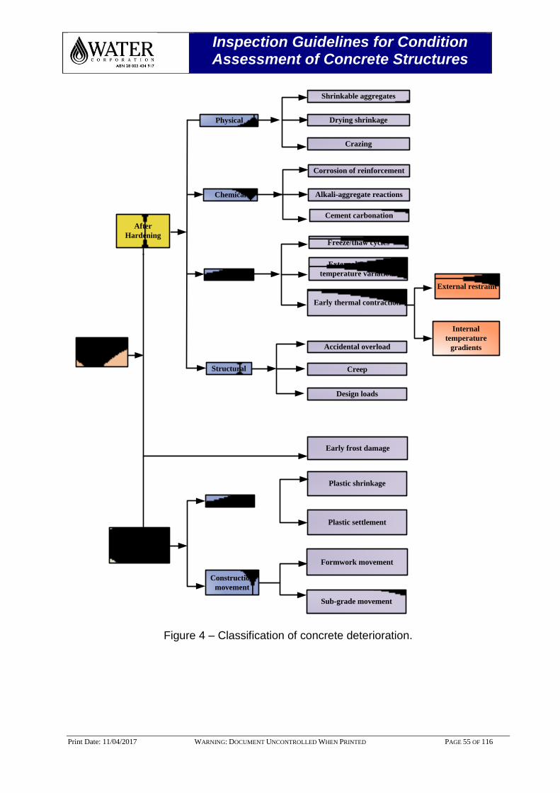
Inspection Guidelines for Condition Assessment of Concrete Structures
Print Date: 11/04/2017 WARNING: DOCUMENT UNCONTROLLED WHEN PRINTED PAGE 55 OF 116
Types of
Crack
Before
Hardening
After
Hardening
Physical
Chemical
Structural
Shrinkable aggregates
Drying shrinkage
Crazing
Corrosion of reinforcement
Alkali-aggregate reactions
Cement carbonation
Freeze/thaw cycles
External Seasonal
temperature variations
Early thermal contraction
External restraint
Internal
temperature
gradientsAccidental overload
Creep
Design loads
Early frost damage
Plastic shrinkage
Plastic settlement
Plastic
Construction
movement
Formwork movement
Sub-grade movement
Thermal
Figure 4 – Classification of concrete deterioration.
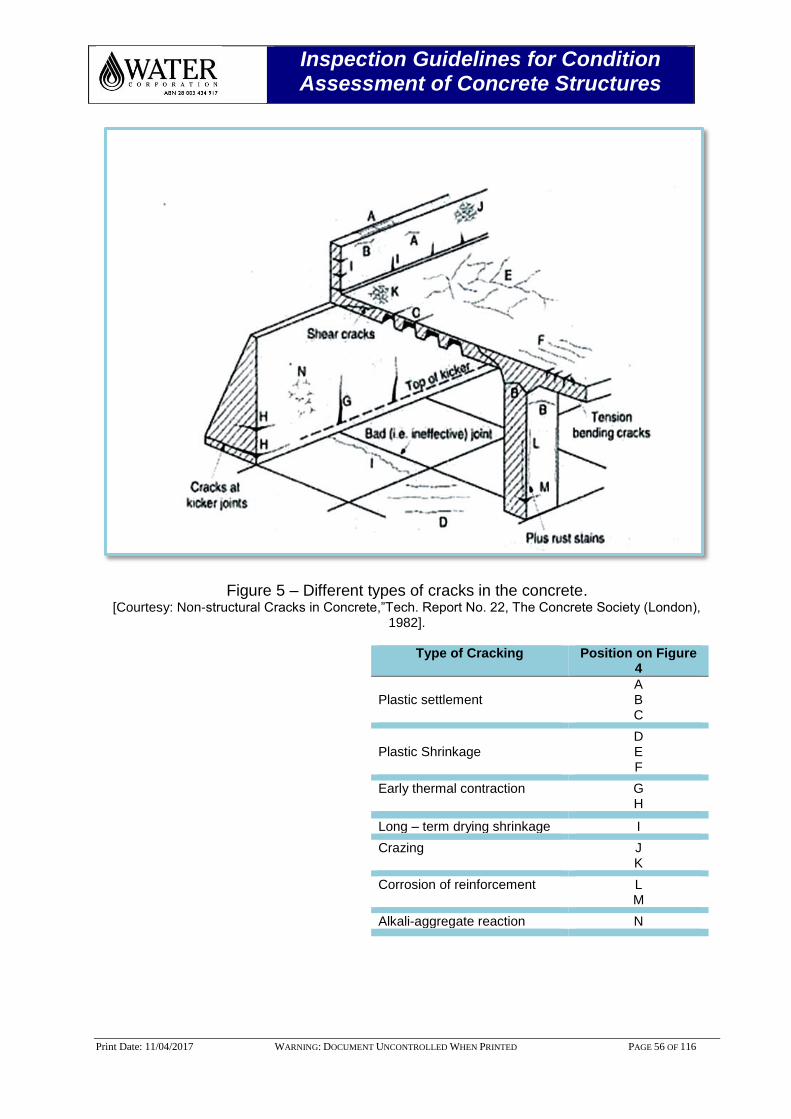
Inspection Guidelines for Condition Assessment of Concrete Structures
Print Date: 11/04/2017 WARNING: DOCUMENT UNCONTROLLED WHEN PRINTED PAGE 56 OF 116
Figure 5 – Different types of cracks in the concrete. [Courtesy: Non-structural Cracks in Concrete,”Tech. Report No. 22, The Concrete Society (London),
1982].
Type of Cracking Position on Figure 4
Plastic settlement
A B C
Plastic Shrinkage
D E F
Early thermal contraction G H
Long – term drying shrinkage I
Crazing J K
Corrosion of reinforcement L M
Alkali-aggregate reaction N
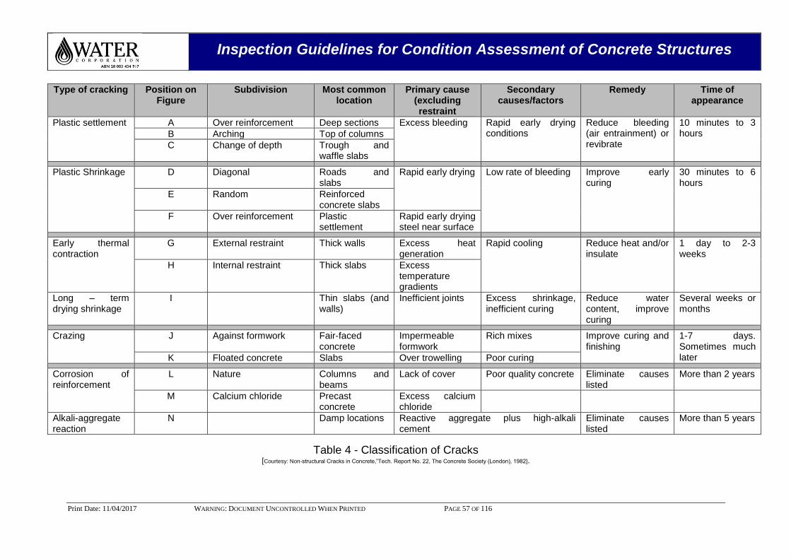
Inspection Guidelines for Condition Assessment of Concrete Structures
Print Date: 11/04/2017 WARNING: DOCUMENT UNCONTROLLED WHEN PRINTED PAGE 57 OF 116
Type of cracking Position on Figure
Subdivision Most common location
Primary cause (excluding restraint
Secondary causes/factors
Remedy Time of appearance
Plastic settlement A Over reinforcement Deep sections Excess bleeding Rapid early drying conditions
Reduce bleeding (air entrainment) or revibrate
10 minutes to 3 hours B Arching Top of columns
C Change of depth Trough and waffle slabs
Plastic Shrinkage D Diagonal Roads and slabs
Rapid early drying Low rate of bleeding Improve early curing
30 minutes to 6 hours
E Random Reinforced concrete slabs
F Over reinforcement Plastic settlement
Rapid early drying steel near surface
Early thermal contraction
G External restraint Thick walls Excess heat generation
Rapid cooling Reduce heat and/or insulate
1 day to 2-3 weeks
H Internal restraint Thick slabs Excess temperature gradients
Long – term drying shrinkage
I Thin slabs (and walls)
Inefficient joints Excess shrinkage, inefficient curing
Reduce water content, improve curing
Several weeks or months
Crazing J Against formwork Fair-faced concrete
Impermeable formwork
Rich mixes Improve curing and finishing
1-7 days. Sometimes much later K Floated concrete Slabs Over trowelling Poor curing
Corrosion of reinforcement
L Nature Columns and beams
Lack of cover Poor quality concrete Eliminate causes listed
More than 2 years
M Calcium chloride Precast concrete
Excess calcium chloride
Alkali-aggregate reaction
N Damp locations Reactive aggregate plus high-alkali cement
Eliminate causes listed
More than 5 years
Table 4 - Classification of Cracks [Courtesy: Non-structural Cracks in Concrete,”Tech. Report No. 22, The Concrete Society (London), 1982].
Inspection Guidelines for Condition Assessment of Concrete Structures
Print Date: 11/04/2017 WARNING: DOCUMENT UNCONTROLLED WHEN PRINTED PAGE 58 OF 116
6.0 DETAILED CONCRETE INSPECTION TECHNIQUES
6.1 Visual Inspection
Visible defects should be recorded in standard template by the ISP’s and record the defects. ISP’s should use the survey legend provided in Appendix G for defect identification. The templates should be devised from asset drawings for a particular type of asset e.g. concrete tank, Clarifier etc. Photographs of the visible defects shall be taken to document the in situ condition, with photo locations clearly noted. Visual inspection will locate areas of advanced reinforcement corrosion, concrete defects and deterioration. It will not provide any information about reinforcement condition in apparently sound concrete. Visual inspections should focus on the following features:
Spalling
Weathering
Insufficient compaction (honeycombing)
Cracks
Rust Stains
Dampness
Efflorescence
The visual survey should also be used to confirm the testing locations so the detailed investigations can confirm the cause of deterioration and represent the condition of the asset. Equipment: Camera, measuring tape, crack width gauge, binoculars, survey proforma, pens, marker/crayon.
6.2 Delamination Survey
A delamination survey involves striking a concrete surface with a small hammer and listening to the noise produced. Sections of concrete that have delaminated from the bulk of the component will sound hollow. Delaminated areas identified shall be marked on the structure and their location and extent recorded on survey proforma. Photographs should be taken of the majority of the delamination. Equipment: Hammer, camera, measuring tape, pens, marker/crayon.
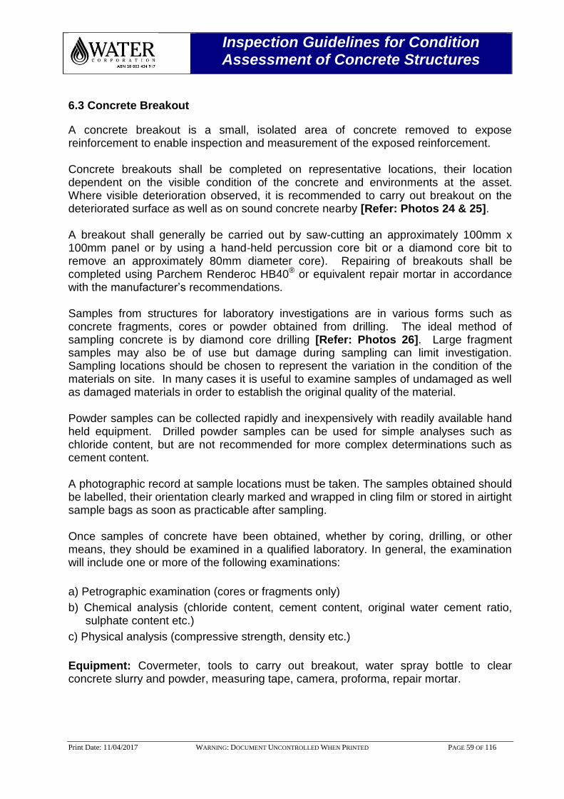
Inspection Guidelines for Condition Assessment of Concrete Structures
Print Date: 11/04/2017 WARNING: DOCUMENT UNCONTROLLED WHEN PRINTED PAGE 59 OF 116
6.3 Concrete Breakout
A concrete breakout is a small, isolated area of concrete removed to expose reinforcement to enable inspection and measurement of the exposed reinforcement. Concrete breakouts shall be completed on representative locations, their location dependent on the visible condition of the concrete and environments at the asset. Where visible deterioration observed, it is recommended to carry out breakout on the deteriorated surface as well as on sound concrete nearby [Refer: Photos 24 & 25]. A breakout shall generally be carried out by saw-cutting an approximately 100mm x 100mm panel or by using a hand-held percussion core bit or a diamond core bit to remove an approximately 80mm diameter core). Repairing of breakouts shall be completed using Parchem Renderoc HB40® or equivalent repair mortar in accordance with the manufacturer’s recommendations. Samples from structures for laboratory investigations are in various forms such as concrete fragments, cores or powder obtained from drilling. The ideal method of sampling concrete is by diamond core drilling [Refer: Photos 26]. Large fragment samples may also be of use but damage during sampling can limit investigation. Sampling locations should be chosen to represent the variation in the condition of the materials on site. In many cases it is useful to examine samples of undamaged as well as damaged materials in order to establish the original quality of the material. Powder samples can be collected rapidly and inexpensively with readily available hand held equipment. Drilled powder samples can be used for simple analyses such as chloride content, but are not recommended for more complex determinations such as cement content. A photographic record at sample locations must be taken. The samples obtained should be labelled, their orientation clearly marked and wrapped in cling film or stored in airtight sample bags as soon as practicable after sampling. Once samples of concrete have been obtained, whether by coring, drilling, or other means, they should be examined in a qualified laboratory. In general, the examination will include one or more of the following examinations:
a) Petrographic examination (cores or fragments only)
b) Chemical analysis (chloride content, cement content, original water cement ratio, sulphate content etc.)
c) Physical analysis (compressive strength, density etc.)
Equipment: Covermeter, tools to carry out breakout, water spray bottle to clear concrete slurry and powder, measuring tape, camera, proforma, repair mortar.
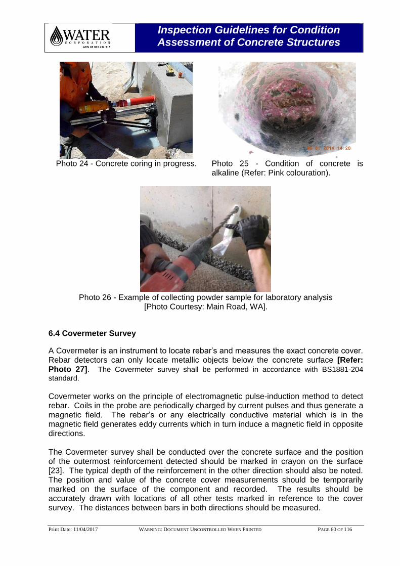
Inspection Guidelines for Condition Assessment of Concrete Structures
Print Date: 11/04/2017 WARNING: DOCUMENT UNCONTROLLED WHEN PRINTED PAGE 60 OF 116
Photo 24 - Concrete coring in progress.
Photo 25 - Condition of concrete is alkaline (Refer: Pink colouration).
Photo 26 - Example of collecting powder sample for laboratory analysis
[Photo Courtesy: Main Road, WA].
6.4 Covermeter Survey
A Covermeter is an instrument to locate rebar’s and measures the exact concrete cover. Rebar detectors can only locate metallic objects below the concrete surface [Refer: Photo 27]. The Covermeter survey shall be performed in accordance with BS1881-204
standard. Covermeter works on the principle of electromagnetic pulse-induction method to detect rebar. Coils in the probe are periodically charged by current pulses and thus generate a magnetic field. The rebar’s or any electrically conductive material which is in the magnetic field generates eddy currents which in turn induce a magnetic field in opposite directions. The Covermeter survey shall be conducted over the concrete surface and the position of the outermost reinforcement detected should be marked in crayon on the surface [23]. The typical depth of the reinforcement in the other direction should also be noted. The position and value of the concrete cover measurements should be temporarily marked on the surface of the component and recorded. The results should be accurately drawn with locations of all other tests marked in reference to the cover survey. The distances between bars in both directions should be measured.
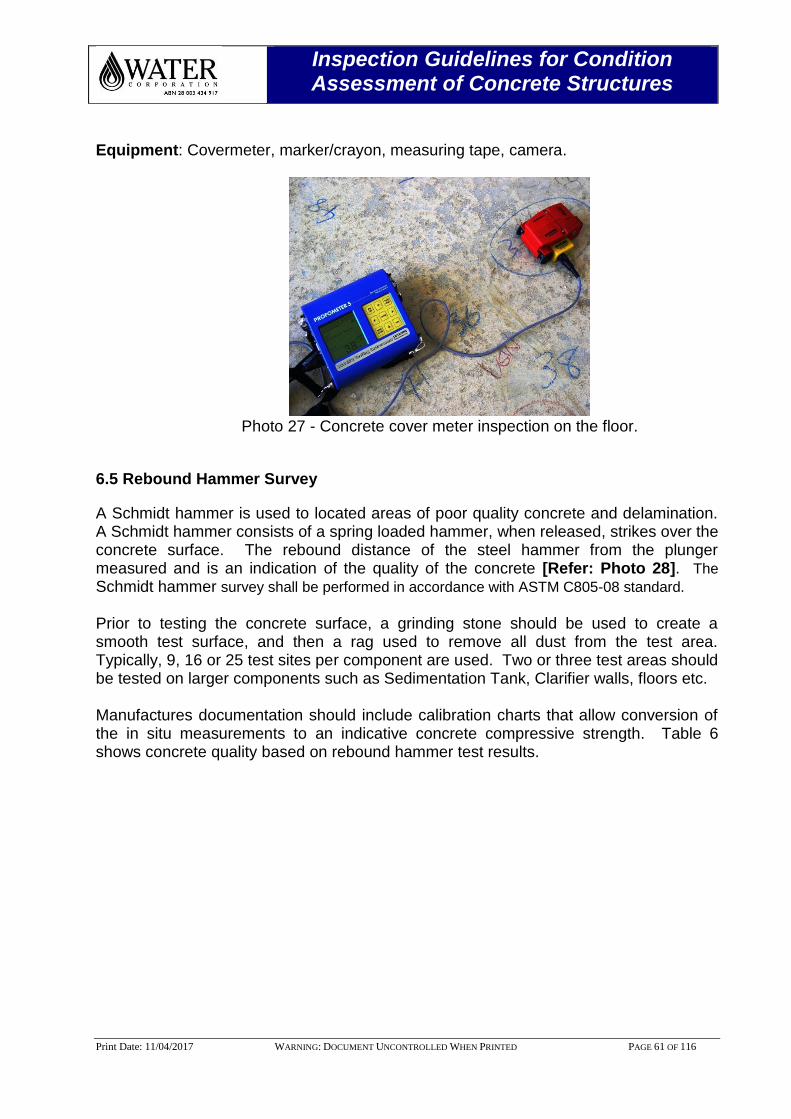
Inspection Guidelines for Condition Assessment of Concrete Structures
Print Date: 11/04/2017 WARNING: DOCUMENT UNCONTROLLED WHEN PRINTED PAGE 61 OF 116
Equipment: Covermeter, marker/crayon, measuring tape, camera.
Photo 27 - Concrete cover meter inspection on the floor.
6.5 Rebound Hammer Survey
A Schmidt hammer is used to located areas of poor quality concrete and delamination. A Schmidt hammer consists of a spring loaded hammer, when released, strikes over the concrete surface. The rebound distance of the steel hammer from the plunger measured and is an indication of the quality of the concrete [Refer: Photo 28]. The
Schmidt hammer survey shall be performed in accordance with ASTM C805-08 standard. Prior to testing the concrete surface, a grinding stone should be used to create a smooth test surface, and then a rag used to remove all dust from the test area. Typically, 9, 16 or 25 test sites per component are used. Two or three test areas should be tested on larger components such as Sedimentation Tank, Clarifier walls, floors etc. Manufactures documentation should include calibration charts that allow conversion of the in situ measurements to an indicative concrete compressive strength. Table 6 shows concrete quality based on rebound hammer test results.
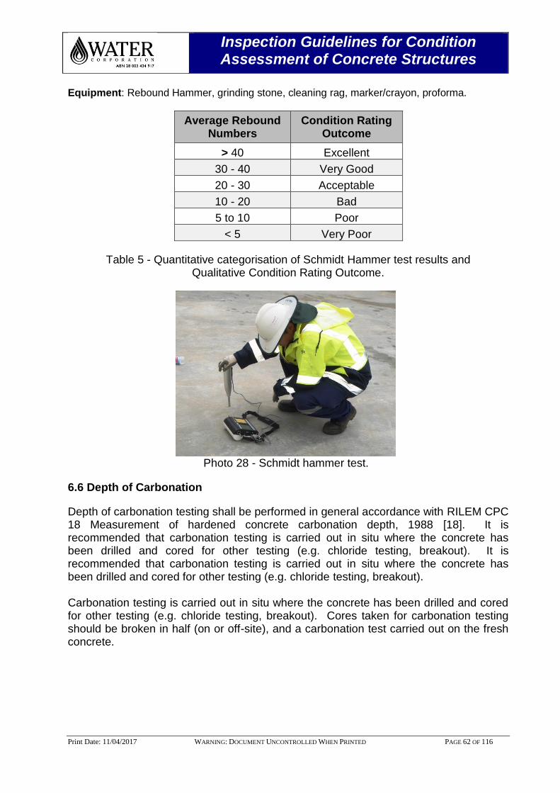
Inspection Guidelines for Condition Assessment of Concrete Structures
Print Date: 11/04/2017 WARNING: DOCUMENT UNCONTROLLED WHEN PRINTED PAGE 62 OF 116
Equipment: Rebound Hammer, grinding stone, cleaning rag, marker/crayon, proforma.
Average Rebound Numbers
Condition Rating Outcome
> 40 Excellent
30 - 40 Very Good
20 - 30 Acceptable
10 - 20 Bad
5 to 10 Poor
< 5 Very Poor
Table 5 - Quantitative categorisation of Schmidt Hammer test results and Qualitative Condition Rating Outcome.
Photo 28 - Schmidt hammer test.
6.6 Depth of Carbonation
Depth of carbonation testing shall be performed in general accordance with RILEM CPC 18 Measurement of hardened concrete carbonation depth, 1988 [18]. It is recommended that carbonation testing is carried out in situ where the concrete has been drilled and cored for other testing (e.g. chloride testing, breakout). It is recommended that carbonation testing is carried out in situ where the concrete has been drilled and cored for other testing (e.g. chloride testing, breakout). Carbonation testing is carried out in situ where the concrete has been drilled and cored for other testing (e.g. chloride testing, breakout). Cores taken for carbonation testing should be broken in half (on or off-site), and a carbonation test carried out on the fresh concrete.
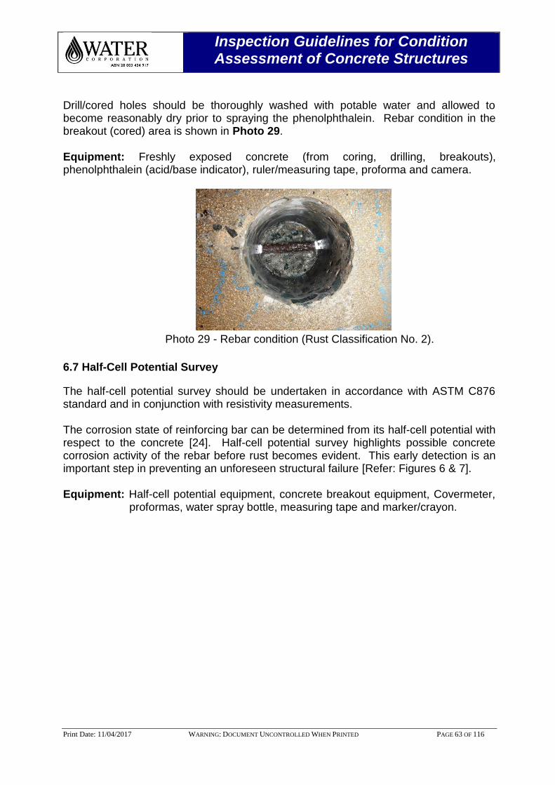
Inspection Guidelines for Condition Assessment of Concrete Structures
Print Date: 11/04/2017 WARNING: DOCUMENT UNCONTROLLED WHEN PRINTED PAGE 63 OF 116
Drill/cored holes should be thoroughly washed with potable water and allowed to become reasonably dry prior to spraying the phenolphthalein. Rebar condition in the breakout (cored) area is shown in Photo 29. Equipment: Freshly exposed concrete (from coring, drilling, breakouts), phenolphthalein (acid/base indicator), ruler/measuring tape, proforma and camera.
Photo 29 - Rebar condition (Rust Classification No. 2).
6.7 Half-Cell Potential Survey
The half-cell potential survey should be undertaken in accordance with ASTM C876 standard and in conjunction with resistivity measurements. The corrosion state of reinforcing bar can be determined from its half-cell potential with respect to the concrete [24]. Half-cell potential survey highlights possible concrete corrosion activity of the rebar before rust becomes evident. This early detection is an important step in preventing an unforeseen structural failure [Refer: Figures 6 & 7]. Equipment: Half-cell potential equipment, concrete breakout equipment, Covermeter,
proformas, water spray bottle, measuring tape and marker/crayon.
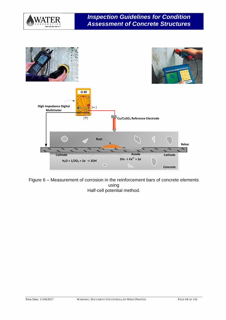
Inspection Guidelines for Condition Assessment of Concrete Structures
Print Date: 11/04/2017 WARNING: DOCUMENT UNCONTROLLED WHEN PRINTED PAGE 64 OF 116
-0.40
High Impedance Digital Multimeter
Cu/CuSO4 Reference Electrode
Rust
Concrete
Rebar
2Fe → Fe2+ + 2e-
H2O + 1/2O2 + 2e- → 2OH-
AnodeCathode Cathode
( )
( )
Figure 6 – Measurement of corrosion in the reinforcement bars of concrete elements using
Half-cell potential method.
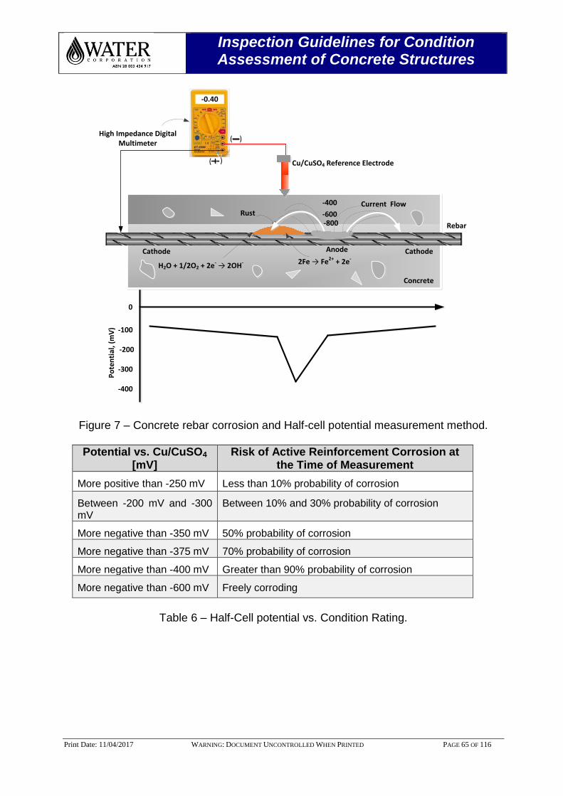
Inspection Guidelines for Condition Assessment of Concrete Structures
Print Date: 11/04/2017 WARNING: DOCUMENT UNCONTROLLED WHEN PRINTED PAGE 65 OF 116
0
-100
-200
-300
-400
-0.40
High Impedance Digital Multimeter
Cu/CuSO4 Reference Electrode
Rust
Concrete
Rebar
2Fe → Fe2+ + 2e-
H2O + 1/2O2 + 2e- → 2OH-
AnodeCathode Cathode
Po
ten
tial
, (m
V)
-400
-600-800
Current Flow
( )
( )
Figure 7 – Concrete rebar corrosion and Half-cell potential measurement method.
Potential vs. Cu/CuSO4
[mV] Risk of Active Reinforcement Corrosion at
the Time of Measurement
More positive than -250 mV Less than 10% probability of corrosion
Between -200 mV and -300 mV
Between 10% and 30% probability of corrosion
More negative than -350 mV 50% probability of corrosion
More negative than -375 mV 70% probability of corrosion
More negative than -400 mV Greater than 90% probability of corrosion
More negative than -600 mV Freely corroding
Table 6 – Half-Cell potential vs. Condition Rating.
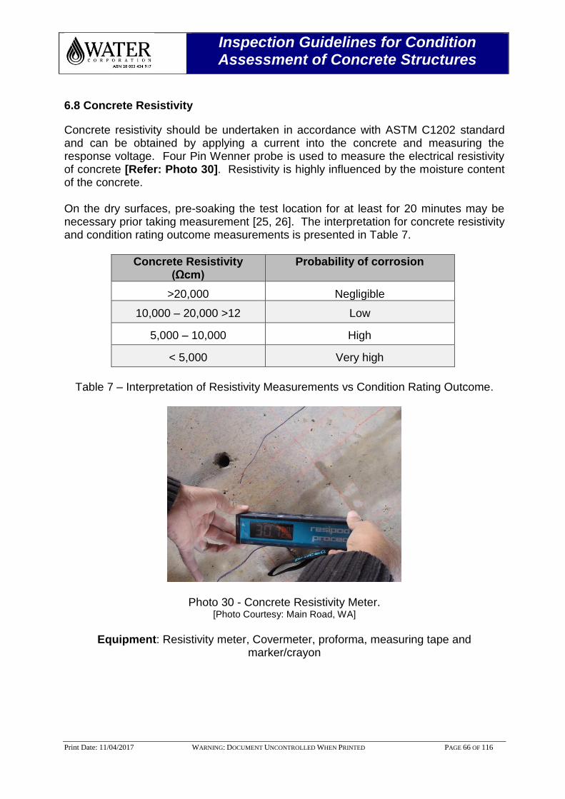
Inspection Guidelines for Condition Assessment of Concrete Structures
Print Date: 11/04/2017 WARNING: DOCUMENT UNCONTROLLED WHEN PRINTED PAGE 66 OF 116
6.8 Concrete Resistivity
Concrete resistivity should be undertaken in accordance with ASTM C1202 standard and can be obtained by applying a current into the concrete and measuring the response voltage. Four Pin Wenner probe is used to measure the electrical resistivity of concrete [Refer: Photo 30]. Resistivity is highly influenced by the moisture content of the concrete. On the dry surfaces, pre-soaking the test location for at least for 20 minutes may be necessary prior taking measurement [25, 26]. The interpretation for concrete resistivity and condition rating outcome measurements is presented in Table 7.
Concrete Resistivity (Ωcm)
Probability of corrosion
>20,000 Negligible
10,000 – 20,000 >12 Low
5,000 – 10,000 High
< 5,000 Very high
Table 7 – Interpretation of Resistivity Measurements vs Condition Rating Outcome.
Photo 30 - Concrete Resistivity Meter. [Photo Courtesy: Main Road, WA]
Equipment: Resistivity meter, Covermeter, proforma, measuring tape and
marker/crayon
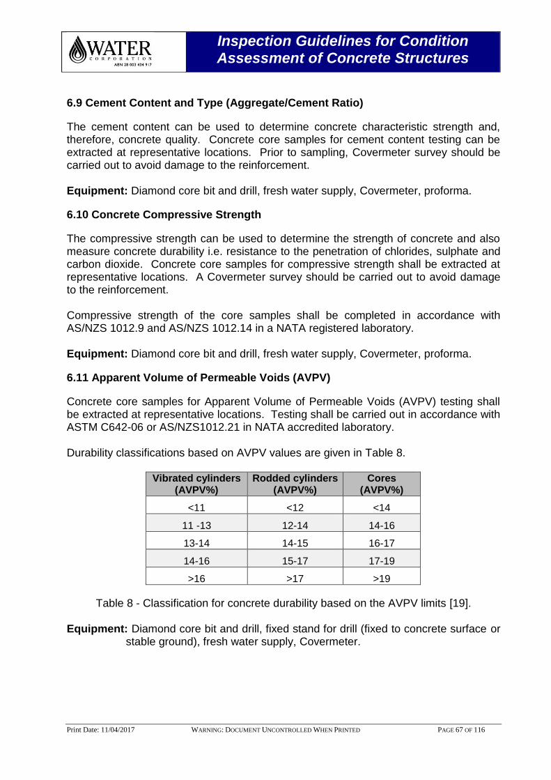
Inspection Guidelines for Condition Assessment of Concrete Structures
Print Date: 11/04/2017 WARNING: DOCUMENT UNCONTROLLED WHEN PRINTED PAGE 67 OF 116
6.9 Cement Content and Type (Aggregate/Cement Ratio)
The cement content can be used to determine concrete characteristic strength and, therefore, concrete quality. Concrete core samples for cement content testing can be extracted at representative locations. Prior to sampling, Covermeter survey should be carried out to avoid damage to the reinforcement. Equipment: Diamond core bit and drill, fresh water supply, Covermeter, proforma.
6.10 Concrete Compressive Strength
The compressive strength can be used to determine the strength of concrete and also measure concrete durability i.e. resistance to the penetration of chlorides, sulphate and carbon dioxide. Concrete core samples for compressive strength shall be extracted at representative locations. A Covermeter survey should be carried out to avoid damage to the reinforcement. Compressive strength of the core samples shall be completed in accordance with AS/NZS 1012.9 and AS/NZS 1012.14 in a NATA registered laboratory. Equipment: Diamond core bit and drill, fresh water supply, Covermeter, proforma.
6.11 Apparent Volume of Permeable Voids (AVPV)
Concrete core samples for Apparent Volume of Permeable Voids (AVPV) testing shall be extracted at representative locations. Testing shall be carried out in accordance with ASTM C642-06 or AS/NZS1012.21 in NATA accredited laboratory. Durability classifications based on AVPV values are given in Table 8.
Vibrated cylinders (AVPV%)
Rodded cylinders (AVPV%)
Cores (AVPV%)
<11 <12 <14
11 -13 12-14 14-16
13-14 14-15 16-17
14-16 15-17 17-19
>16 >17 >19
Table 8 - Classification for concrete durability based on the AVPV limits [19].
Equipment: Diamond core bit and drill, fixed stand for drill (fixed to concrete surface or stable ground), fresh water supply, Covermeter.
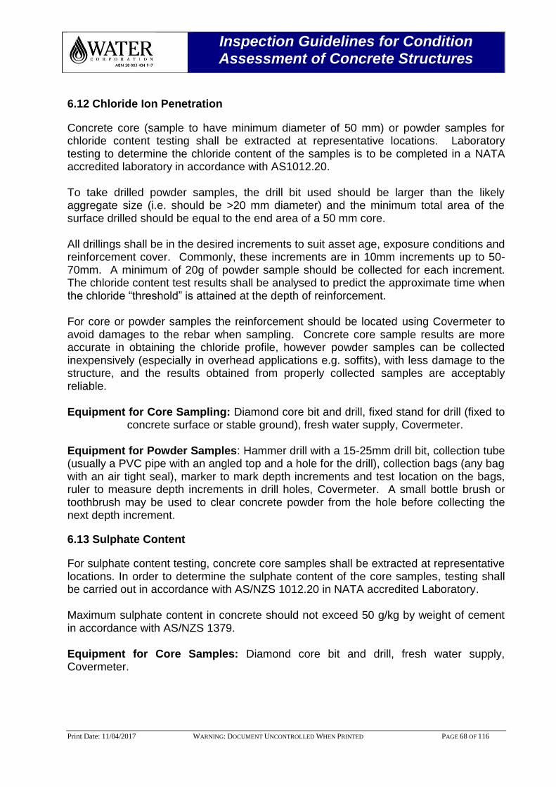
Inspection Guidelines for Condition Assessment of Concrete Structures
Print Date: 11/04/2017 WARNING: DOCUMENT UNCONTROLLED WHEN PRINTED PAGE 68 OF 116
6.12 Chloride Ion Penetration
Concrete core (sample to have minimum diameter of 50 mm) or powder samples for chloride content testing shall be extracted at representative locations. Laboratory testing to determine the chloride content of the samples is to be completed in a NATA accredited laboratory in accordance with AS1012.20. To take drilled powder samples, the drill bit used should be larger than the likely aggregate size (i.e. should be >20 mm diameter) and the minimum total area of the surface drilled should be equal to the end area of a 50 mm core. All drillings shall be in the desired increments to suit asset age, exposure conditions and reinforcement cover. Commonly, these increments are in 10mm increments up to 50-70mm. A minimum of 20g of powder sample should be collected for each increment. The chloride content test results shall be analysed to predict the approximate time when the chloride “threshold” is attained at the depth of reinforcement. For core or powder samples the reinforcement should be located using Covermeter to avoid damages to the rebar when sampling. Concrete core sample results are more accurate in obtaining the chloride profile, however powder samples can be collected inexpensively (especially in overhead applications e.g. soffits), with less damage to the structure, and the results obtained from properly collected samples are acceptably reliable. Equipment for Core Sampling: Diamond core bit and drill, fixed stand for drill (fixed to
concrete surface or stable ground), fresh water supply, Covermeter. Equipment for Powder Samples: Hammer drill with a 15-25mm drill bit, collection tube (usually a PVC pipe with an angled top and a hole for the drill), collection bags (any bag with an air tight seal), marker to mark depth increments and test location on the bags, ruler to measure depth increments in drill holes, Covermeter. A small bottle brush or toothbrush may be used to clear concrete powder from the hole before collecting the next depth increment.
6.13 Sulphate Content
For sulphate content testing, concrete core samples shall be extracted at representative locations. In order to determine the sulphate content of the core samples, testing shall be carried out in accordance with AS/NZS 1012.20 in NATA accredited Laboratory. Maximum sulphate content in concrete should not exceed 50 g/kg by weight of cement in accordance with AS/NZS 1379. Equipment for Core Samples: Diamond core bit and drill, fresh water supply, Covermeter.
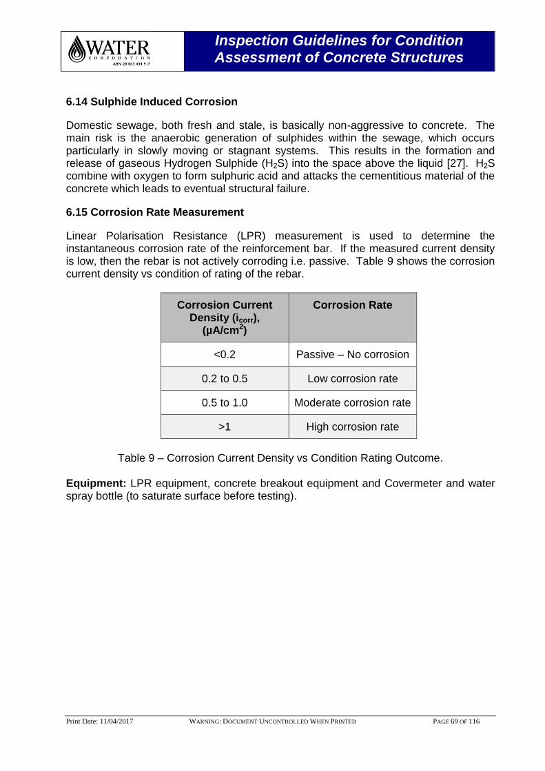
Inspection Guidelines for Condition Assessment of Concrete Structures
Print Date: 11/04/2017 WARNING: DOCUMENT UNCONTROLLED WHEN PRINTED PAGE 69 OF 116
6.14 Sulphide Induced Corrosion
Domestic sewage, both fresh and stale, is basically non-aggressive to concrete. The main risk is the anaerobic generation of sulphides within the sewage, which occurs particularly in slowly moving or stagnant systems. This results in the formation and release of gaseous Hydrogen Sulphide (H2S) into the space above the liquid [27]. H2S combine with oxygen to form sulphuric acid and attacks the cementitious material of the concrete which leads to eventual structural failure.
6.15 Corrosion Rate Measurement
Linear Polarisation Resistance (LPR) measurement is used to determine the instantaneous corrosion rate of the reinforcement bar. If the measured current density is low, then the rebar is not actively corroding i.e. passive. Table 9 shows the corrosion current density vs condition of rating of the rebar.
Corrosion Current Density (icorr),
(µA/cm2)
Corrosion Rate
<0.2 Passive – No corrosion
0.2 to 0.5 Low corrosion rate
0.5 to 1.0 Moderate corrosion rate
>1 High corrosion rate
Table 9 – Corrosion Current Density vs Condition Rating Outcome.
Equipment: LPR equipment, concrete breakout equipment and Covermeter and water spray bottle (to saturate surface before testing).
Inspection Guidelines for Condition Assessment of Concrete Structures
Print Date: 11/04/2017 WARNING: DOCUMENT UNCONTROLLED WHEN PRINTED PAGE 70 OF 116
6.16 Petrographic Analysis
A petrographic test can be used to determine chemical and physical irregularities in concrete. This test should be performed by an appropriately experienced laboratory on cores taken from the asset. The reinforcement should be located to avoid it when breakout and the core should be taken from sound concrete. Equipment for Core Samples: Diamond core bit and drill, fixed stand for drill (fixed to concrete surface or stable ground), fresh water supply, Covermeter, proforma.
6.17 Ultrasonic Pulse Velocity
This technique measures the transit time (in microseconds) of ultra-sound waves passing from an emitter transducer through a concrete sample to a receiver transducer. Faster the transmission time, more dense the concrete and hence better quality of the concrete and is shown in Table 10.
Longitudinal Pulse Velocity, km/s
Condition Rating Outcome
>4.5 Excellent
3.5 – 4.5 Very Good
3.0 – 3.5 Acceptable
2.0 – 3.0 Bad/Poor
<2.0 Very poor
Table 10 - Classification of the quality of concrete on the basis of pulse velocity [25].
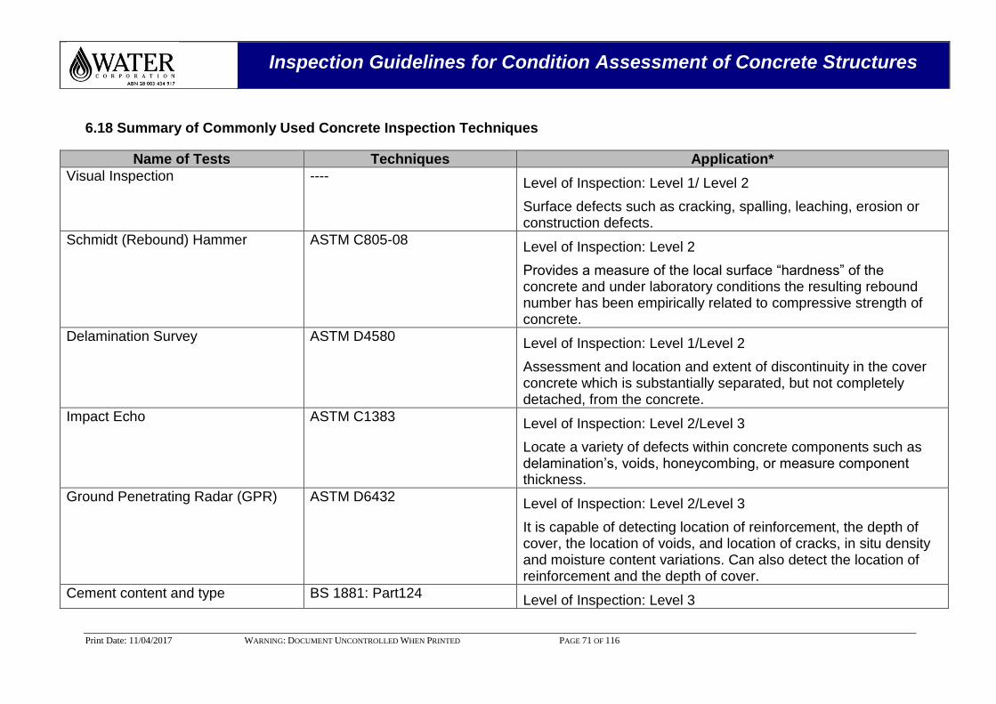
Inspection Guidelines for Condition Assessment of Concrete Structures
Print Date: 11/04/2017 WARNING: DOCUMENT UNCONTROLLED WHEN PRINTED PAGE 71 OF 116
6.18 Summary of Commonly Used Concrete Inspection Techniques
Name of Tests Techniques Application*
Visual Inspection ---- Level of Inspection: Level 1/ Level 2
Surface defects such as cracking, spalling, leaching, erosion or construction defects.
Schmidt (Rebound) Hammer ASTM C805-08
Level of Inspection: Level 2
Provides a measure of the local surface “hardness” of the concrete and under laboratory conditions the resulting rebound number has been empirically related to compressive strength of concrete.
Delamination Survey
ASTM D4580
Level of Inspection: Level 1/Level 2
Assessment and location and extent of discontinuity in the cover concrete which is substantially separated, but not completely detached, from the concrete.
Impact Echo ASTM C1383
Level of Inspection: Level 2/Level 3
Locate a variety of defects within concrete components such as delamination’s, voids, honeycombing, or measure component thickness.
Ground Penetrating Radar (GPR) ASTM D6432
Level of Inspection: Level 2/Level 3
It is capable of detecting location of reinforcement, the depth of cover, the location of voids, and location of cracks, in situ density and moisture content variations. Can also detect the location of reinforcement and the depth of cover.
Cement content and type BS 1881: Part124 Level of Inspection: Level 3
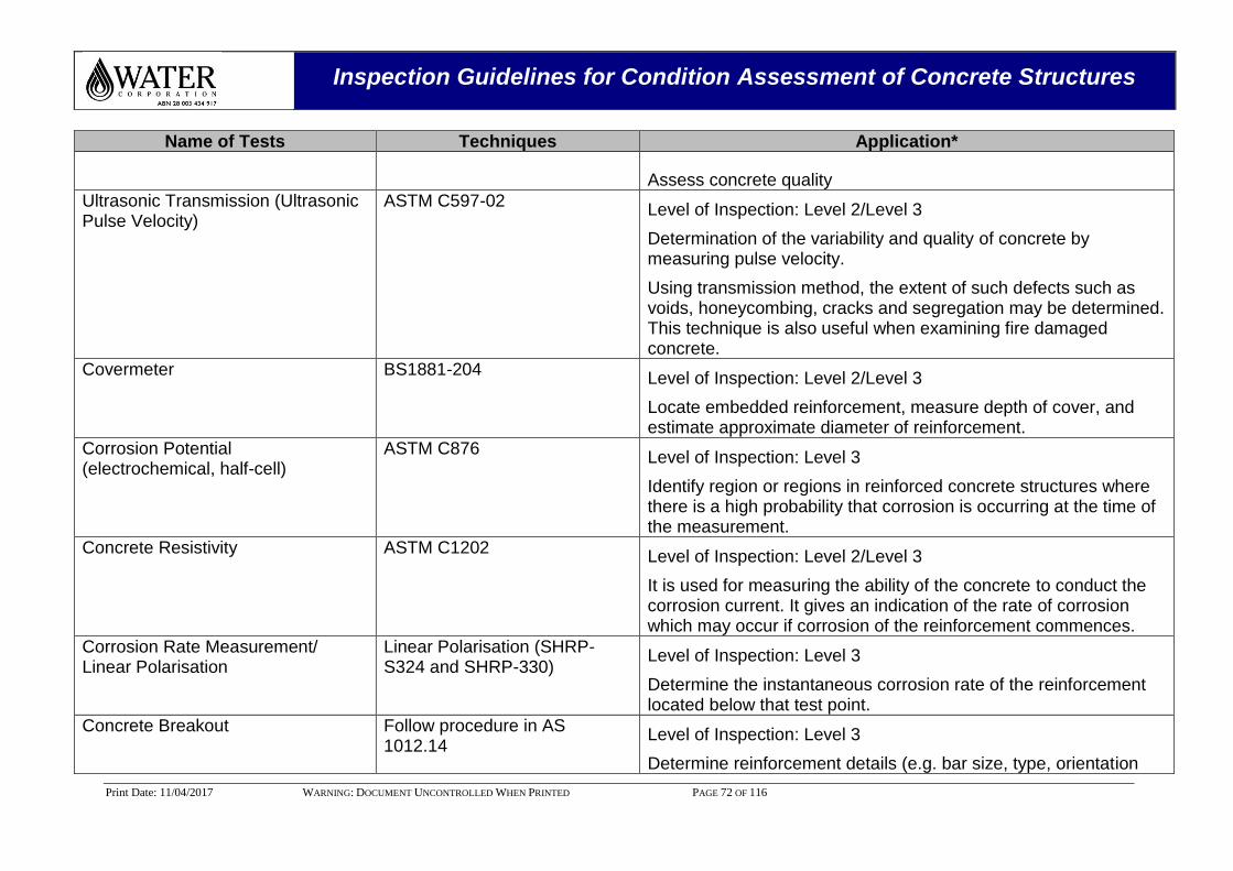
Inspection Guidelines for Condition Assessment of Concrete Structures
Print Date: 11/04/2017 WARNING: DOCUMENT UNCONTROLLED WHEN PRINTED PAGE 72 OF 116
Name of Tests Techniques Application*
Assess concrete quality
Ultrasonic Transmission (Ultrasonic Pulse Velocity)
ASTM C597-02 Level of Inspection: Level 2/Level 3
Determination of the variability and quality of concrete by measuring pulse velocity.
Using transmission method, the extent of such defects such as voids, honeycombing, cracks and segregation may be determined. This technique is also useful when examining fire damaged concrete.
Covermeter BS1881-204 Level of Inspection: Level 2/Level 3
Locate embedded reinforcement, measure depth of cover, and estimate approximate diameter of reinforcement.
Corrosion Potential (electrochemical, half-cell)
ASTM C876
Level of Inspection: Level 3
Identify region or regions in reinforced concrete structures where there is a high probability that corrosion is occurring at the time of the measurement.
Concrete Resistivity ASTM C1202 Level of Inspection: Level 2/Level 3
It is used for measuring the ability of the concrete to conduct the corrosion current. It gives an indication of the rate of corrosion which may occur if corrosion of the reinforcement commences.
Corrosion Rate Measurement/ Linear Polarisation
Linear Polarisation (SHRP-S324 and SHRP-330)
Level of Inspection: Level 3
Determine the instantaneous corrosion rate of the reinforcement located below that test point.
Concrete Breakout Follow procedure in AS 1012.14
Level of Inspection: Level 3
Determine reinforcement details (e.g. bar size, type, orientation
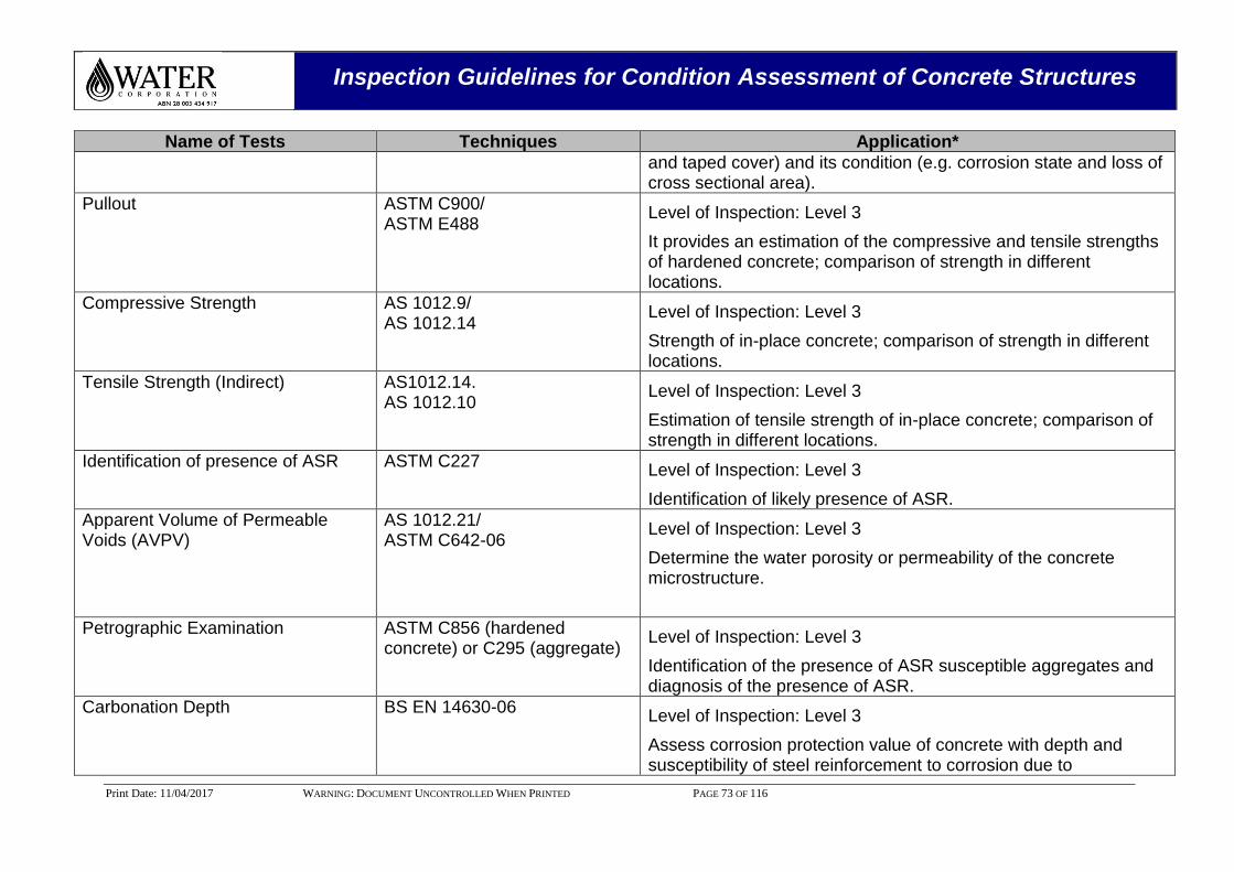
Inspection Guidelines for Condition Assessment of Concrete Structures
Print Date: 11/04/2017 WARNING: DOCUMENT UNCONTROLLED WHEN PRINTED PAGE 73 OF 116
Name of Tests Techniques Application*
and taped cover) and its condition (e.g. corrosion state and loss of cross sectional area).
Pullout ASTM C900/ ASTM E488
Level of Inspection: Level 3
It provides an estimation of the compressive and tensile strengths of hardened concrete; comparison of strength in different locations.
Compressive Strength AS 1012.9/ AS 1012.14
Level of Inspection: Level 3
Strength of in-place concrete; comparison of strength in different locations.
Tensile Strength (Indirect) AS1012.14. AS 1012.10
Level of Inspection: Level 3
Estimation of tensile strength of in-place concrete; comparison of strength in different locations.
Identification of presence of ASR ASTM C227 Level of Inspection: Level 3
Identification of likely presence of ASR.
Apparent Volume of Permeable Voids (AVPV)
AS 1012.21/ ASTM C642-06
Level of Inspection: Level 3
Determine the water porosity or permeability of the concrete microstructure.
Petrographic Examination ASTM C856 (hardened concrete) or C295 (aggregate)
Level of Inspection: Level 3
Identification of the presence of ASR susceptible aggregates and diagnosis of the presence of ASR.
Carbonation Depth BS EN 14630-06 Level of Inspection: Level 3
Assess corrosion protection value of concrete with depth and susceptibility of steel reinforcement to corrosion due to
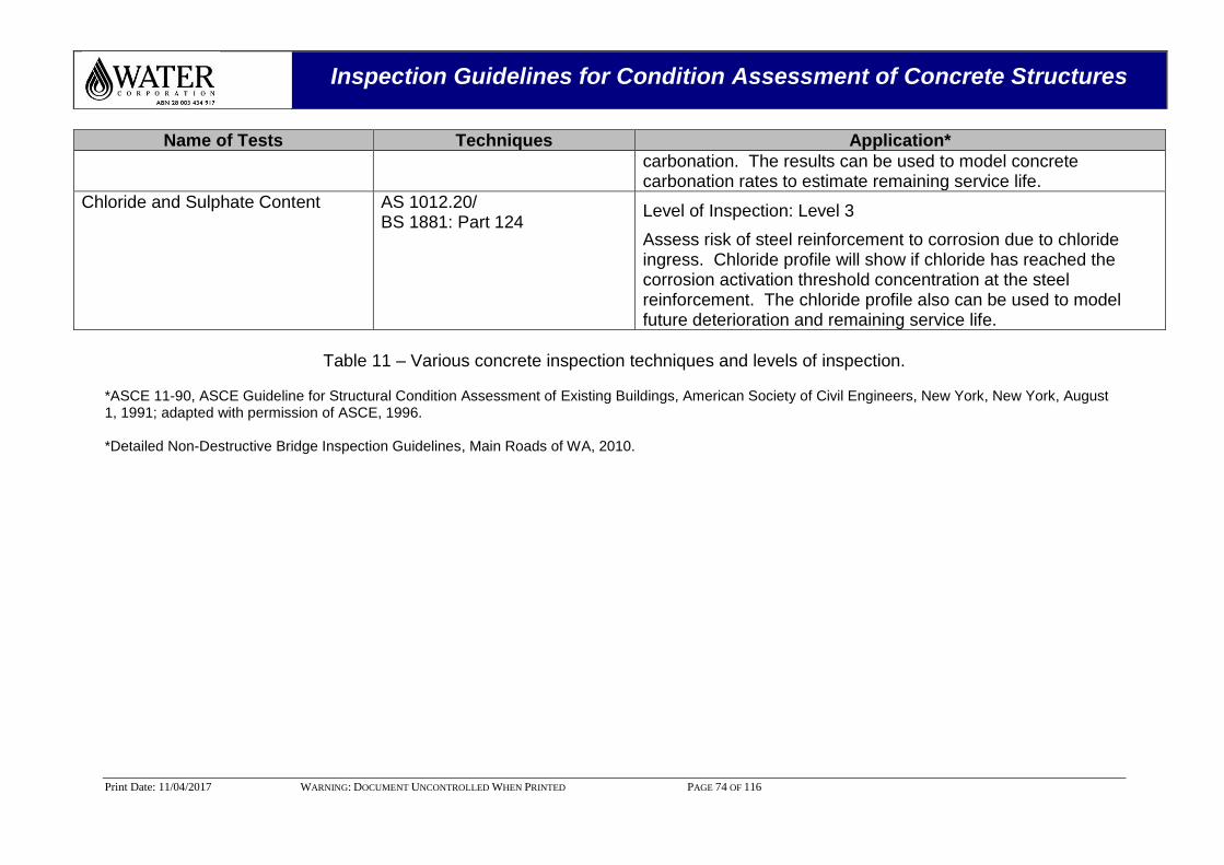
Inspection Guidelines for Condition Assessment of Concrete Structures
Print Date: 11/04/2017 WARNING: DOCUMENT UNCONTROLLED WHEN PRINTED PAGE 74 OF 116
Name of Tests Techniques Application*
carbonation. The results can be used to model concrete carbonation rates to estimate remaining service life.
Chloride and Sulphate Content AS 1012.20/ BS 1881: Part 124
Level of Inspection: Level 3
Assess risk of steel reinforcement to corrosion due to chloride ingress. Chloride profile will show if chloride has reached the corrosion activation threshold concentration at the steel reinforcement. The chloride profile also can be used to model future deterioration and remaining service life.
Table 11 – Various concrete inspection techniques and levels of inspection.
*ASCE 11-90, ASCE Guideline for Structural Condition Assessment of Existing Buildings, American Society of Civil Engineers, New York, New York, August 1, 1991; adapted with permission of ASCE, 1996. *Detailed Non-Destructive Bridge Inspection Guidelines, Main Roads of WA, 2010.
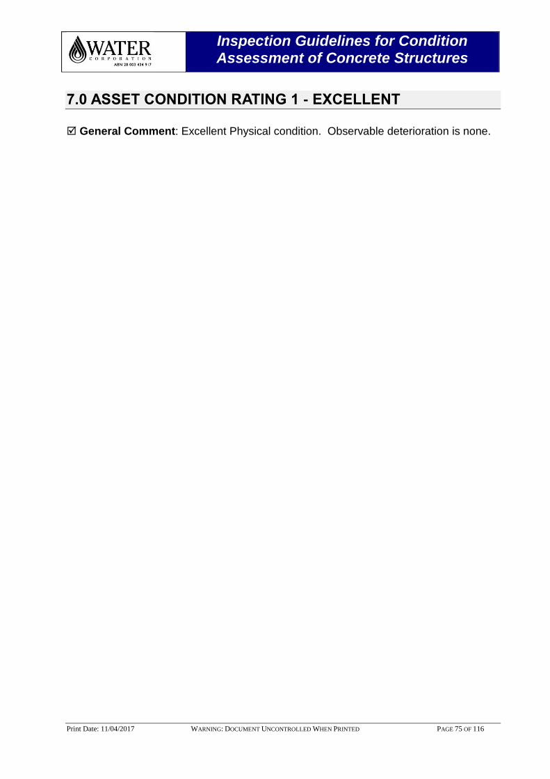
Inspection Guidelines for Condition Assessment of Concrete Structures
Print Date: 11/04/2017 WARNING: DOCUMENT UNCONTROLLED WHEN PRINTED PAGE 75 OF 116
7.0 ASSET CONDITION RATING 1 - EXCELLENT
General Comment: Excellent Physical condition. Observable deterioration is none.
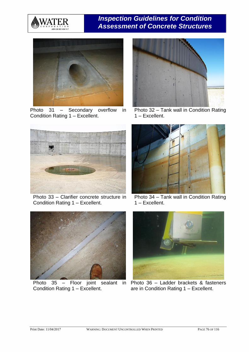
Inspection Guidelines for Condition Assessment of Concrete Structures
Print Date: 11/04/2017 WARNING: DOCUMENT UNCONTROLLED WHEN PRINTED PAGE 76 OF 116
Photo 31 – Secondary overflow in Condition Rating 1 – Excellent.
Photo 32 – Tank wall in Condition Rating 1 – Excellent.
Photo 33 – Clarifier concrete structure in Condition Rating 1 – Excellent.
Photo 34 – Tank wall in Condition Rating 1 – Excellent.
Photo 35 – Floor joint sealant in Condition Rating 1 – Excellent.
Photo 36 – Ladder brackets & fasteners are in Condition Rating 1 – Excellent.
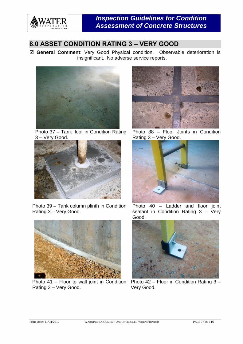
Inspection Guidelines for Condition Assessment of Concrete Structures
Print Date: 11/04/2017 WARNING: DOCUMENT UNCONTROLLED WHEN PRINTED PAGE 77 OF 116
8.0 ASSET CONDITION RATING 3 – VERY GOOD
General Comment: Very Good Physical condition. Observable deterioration is insignificant. No adverse service reports.
Photo 37 – Tank floor in Condition Rating 3 – Very Good.
Photo 38 – Floor Joints in Condition Rating 3 – Very Good.
Photo 39 – Tank column plinth in Condition Rating 3 – Very Good.
Photo 40 – Ladder and floor joint sealant in Condition Rating 3 – Very Good.
Photo 41 – Floor to wall joint in Condition Rating 3 – Very Good.
Photo 42 – Floor in Condition Rating 3 – Very Good.
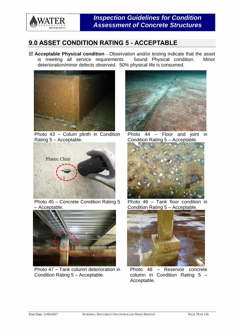
Inspection Guidelines for Condition Assessment of Concrete Structures
Print Date: 11/04/2017 WARNING: DOCUMENT UNCONTROLLED WHEN PRINTED PAGE 78 OF 116
9.0 ASSET CONDITION RATING 5 - ACCEPTABLE
Acceptable Physical condition - Observation and/or testing indicate that the asset is meeting all service requirements. Sound Physical condition. Minor deterioration/minor defects observed. 50% physical life is consumed.
Photo 43 – Colum plinth in Condition Rating 5 – Acceptable.
Photo 44 – Floor and joint in Condition Rating 5 – Acceptable.
Photo 45 – Concrete Condition Rating 5 – Acceptable.
Photo 46 – Tank floor condition in Condition Rating 5 – Acceptable.
Photo 47 – Tank column deterioration in Condition Rating 5 – Acceptable.
Photo 48 – Reservoir concrete column in Condition Rating 5 – Acceptable.
Plastic Chair
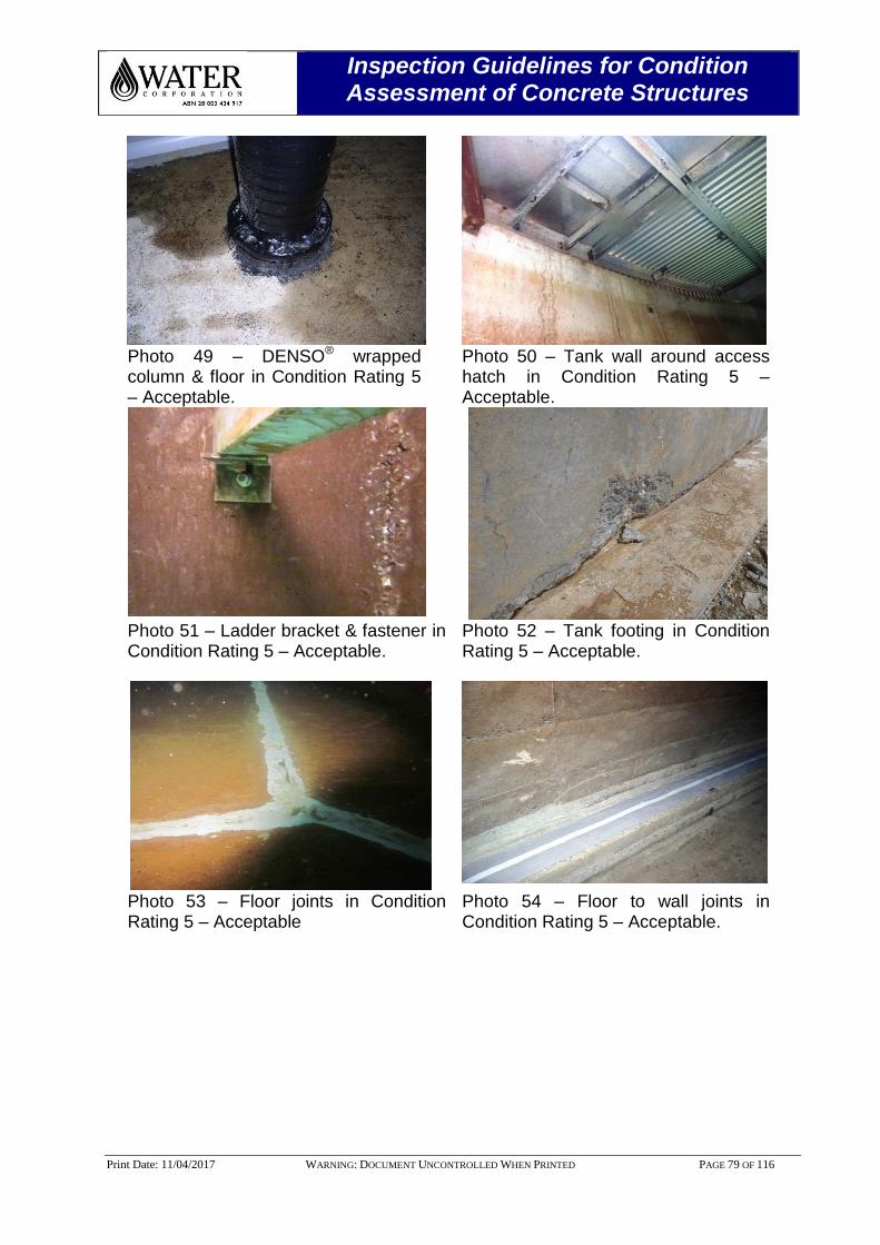
Inspection Guidelines for Condition Assessment of Concrete Structures
Print Date: 11/04/2017 WARNING: DOCUMENT UNCONTROLLED WHEN PRINTED PAGE 79 OF 116
Photo 49 – DENSO® wrapped column & floor in Condition Rating 5 – Acceptable.
Photo 50 – Tank wall around access hatch in Condition Rating 5 – Acceptable.
Photo 51 – Ladder bracket & fastener in Condition Rating 5 – Acceptable.
Photo 52 – Tank footing in Condition Rating 5 – Acceptable.
Photo 53 – Floor joints in Condition Rating 5 – Acceptable
Photo 54 – Floor to wall joints in Condition Rating 5 – Acceptable.
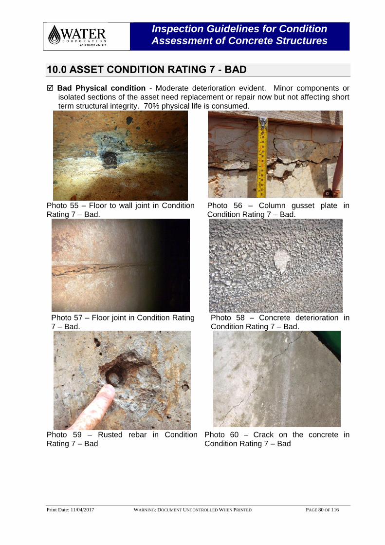
Inspection Guidelines for Condition Assessment of Concrete Structures
Print Date: 11/04/2017 WARNING: DOCUMENT UNCONTROLLED WHEN PRINTED PAGE 80 OF 116
10.0 ASSET CONDITION RATING 7 - BAD
Bad Physical condition - Moderate deterioration evident. Minor components or isolated sections of the asset need replacement or repair now but not affecting short term structural integrity. 70% physical life is consumed.
Photo 55 – Floor to wall joint in Condition Rating 7 – Bad.
Photo 56 – Column gusset plate in Condition Rating 7 – Bad.
Photo 57 – Floor joint in Condition Rating 7 – Bad.
Photo 58 – Concrete deterioration in Condition Rating 7 – Bad.
Photo 59 – Rusted rebar in Condition Rating 7 – Bad
Photo 60 – Crack on the concrete in Condition Rating 7 – Bad
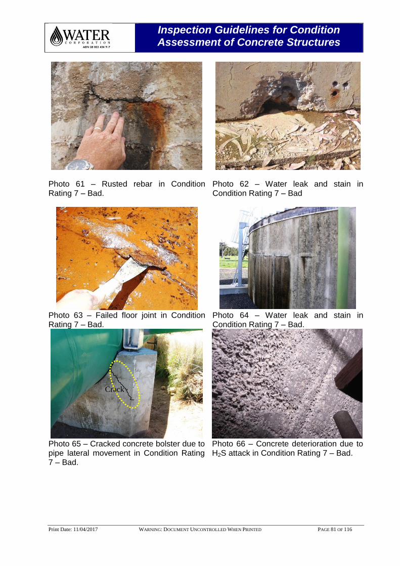
Inspection Guidelines for Condition Assessment of Concrete Structures
Print Date: 11/04/2017 WARNING: DOCUMENT UNCONTROLLED WHEN PRINTED PAGE 81 OF 116
Photo 61 – Rusted rebar in Condition Rating 7 – Bad.
Photo 62 – Water leak and stain in Condition Rating 7 – Bad
Photo 63 – Failed floor joint in Condition Rating 7 – Bad.
Photo 64 – Water leak and stain in Condition Rating 7 – Bad.
Photo 65 – Cracked concrete bolster due to pipe lateral movement in Condition Rating 7 – Bad.
Photo 66 – Concrete deterioration due to H2S attack in Condition Rating 7 – Bad.
Crack
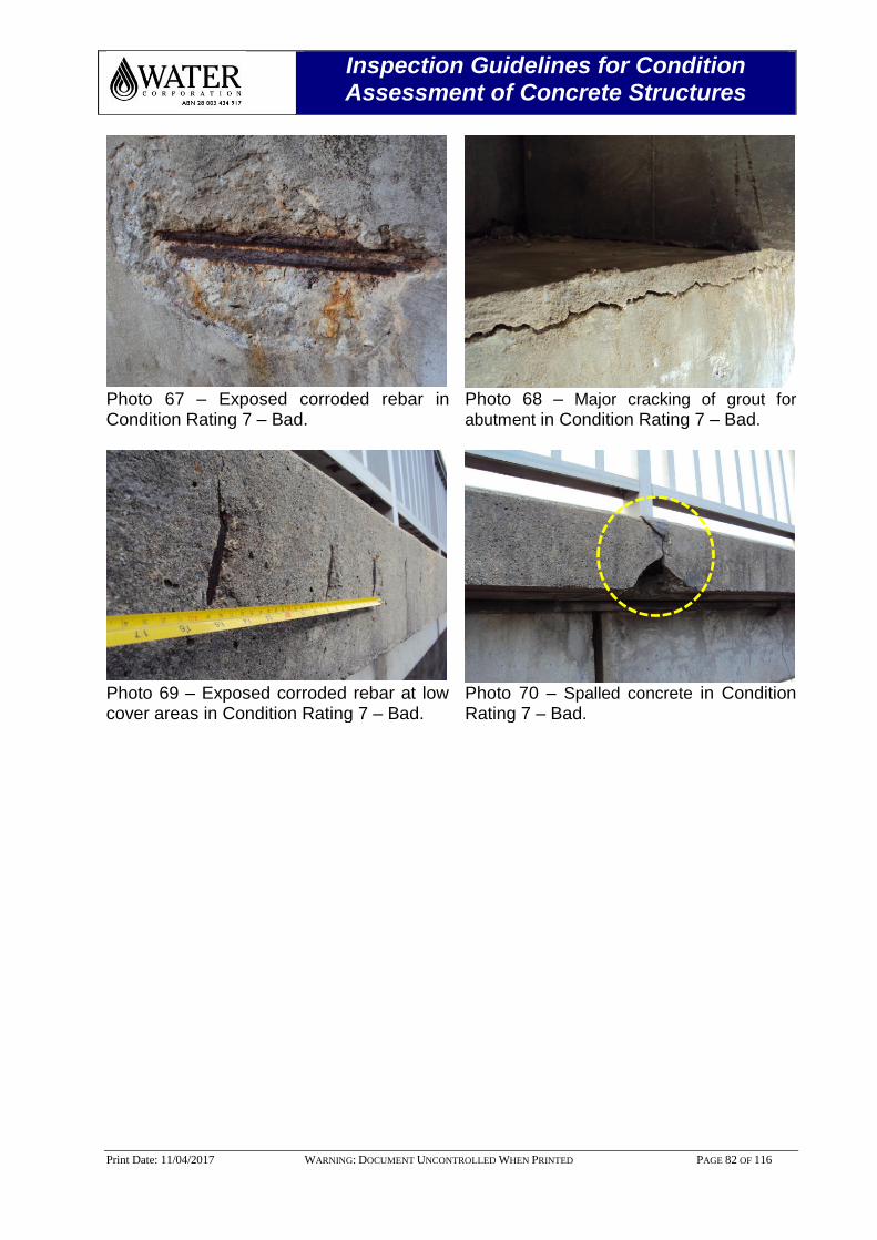
Inspection Guidelines for Condition Assessment of Concrete Structures
Print Date: 11/04/2017 WARNING: DOCUMENT UNCONTROLLED WHEN PRINTED PAGE 82 OF 116
Photo 67 – Exposed corroded rebar in Condition Rating 7 – Bad.
Photo 68 – Major cracking of grout for
abutment in Condition Rating 7 – Bad.
Photo 69 – Exposed corroded rebar at low cover areas in Condition Rating 7 – Bad.
Photo 70 – Spalled concrete in Condition Rating 7 – Bad.

Inspection Guidelines for Condition Assessment of Concrete Structures
Print Date: 11/04/2017 WARNING: DOCUMENT UNCONTROLLED WHEN PRINTED PAGE 83 OF 116
11.0 ASSET CONDITION RATING 9 - POOR
Poor Physical condition - Serious/Significant deterioration evident and affecting
structural integrity. Asset is now moving into zone of failure. 90% physical life is consumed.
Photo 71 – Floor crack in Condition Rating 9 – Poor.
Photo 72 – Leaking water tank in Condition Rating 9 – Poor.
Photo 73 – Tank leak in Condition Rating 9 – Poor.
Photo 74 – Floor crack in Condition Rating 9 – Poor.
Photo 75 – Floor joint sealant in Condition Rating 9 – Poor.
Photo 76 – H2S attacked outlet channel in Condition Rating 9 – Poor.
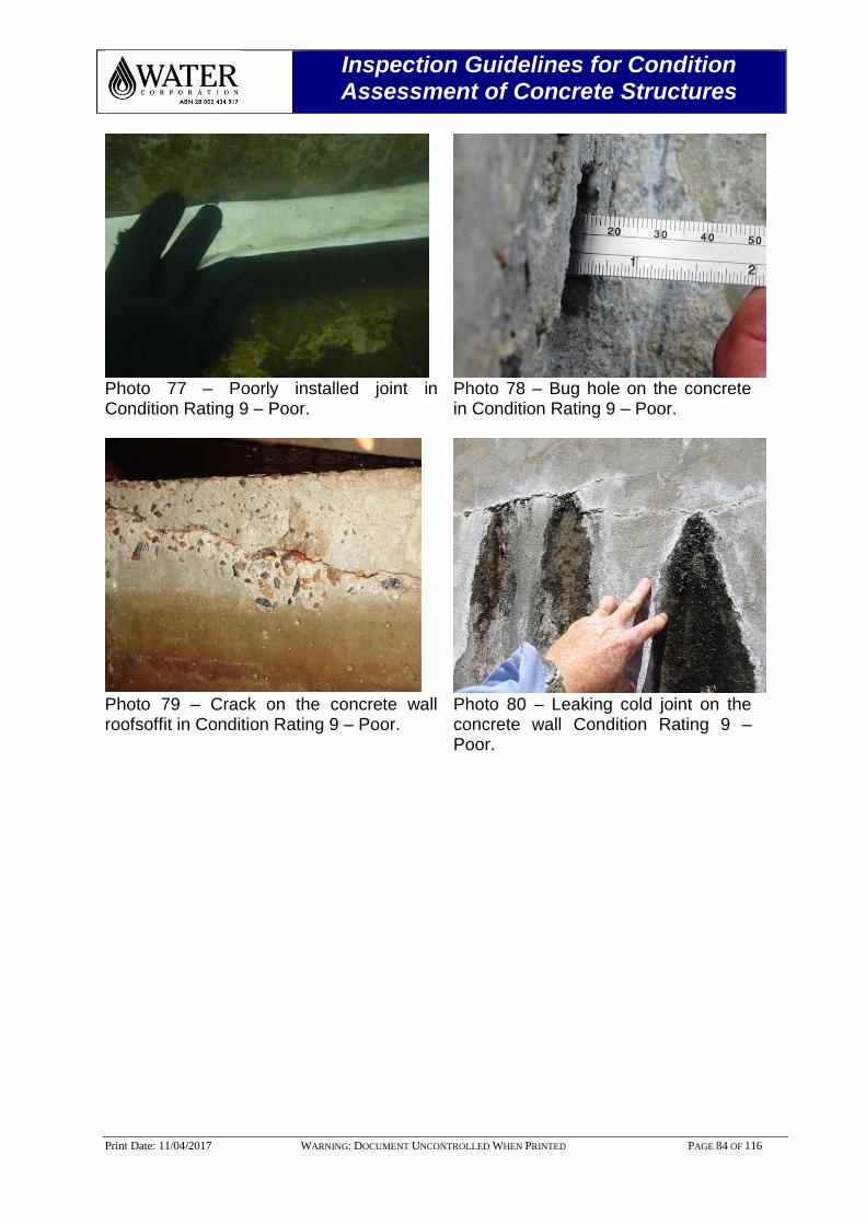
Inspection Guidelines for Condition Assessment of Concrete Structures
Print Date: 11/04/2017 WARNING: DOCUMENT UNCONTROLLED WHEN PRINTED PAGE 84 OF 116
Photo 77 – Poorly installed joint in Condition Rating 9 – Poor.
Photo 78 – Bug hole on the concrete in Condition Rating 9 – Poor.
Photo 79 – Crack on the concrete wall roofsoffit in Condition Rating 9 – Poor.
Photo 80 – Leaking cold joint on the concrete wall Condition Rating 9 – Poor.
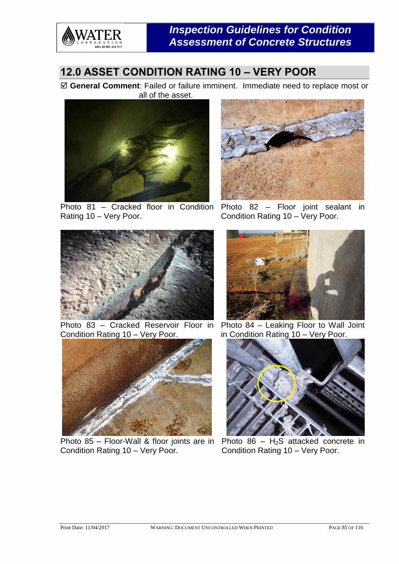
Inspection Guidelines for Condition Assessment of Concrete Structures
Print Date: 11/04/2017 WARNING: DOCUMENT UNCONTROLLED WHEN PRINTED PAGE 85 OF 116
12.0 ASSET CONDITION RATING 10 – VERY POOR
General Comment: Failed or failure imminent. Immediate need to replace most or all of the asset.
Photo 81 – Cracked floor in Condition Rating 10 – Very Poor.
Photo 82 – Floor joint sealant in Condition Rating 10 – Very Poor.
Photo 83 – Cracked Reservoir Floor in Condition Rating 10 – Very Poor.
Photo 84 – Leaking Floor to Wall Joint in Condition Rating 10 – Very Poor.
Photo 85 – Floor-Wall & floor joints are in Condition Rating 10 – Very Poor.
Photo 86 – H2S attacked concrete in Condition Rating 10 – Very Poor.
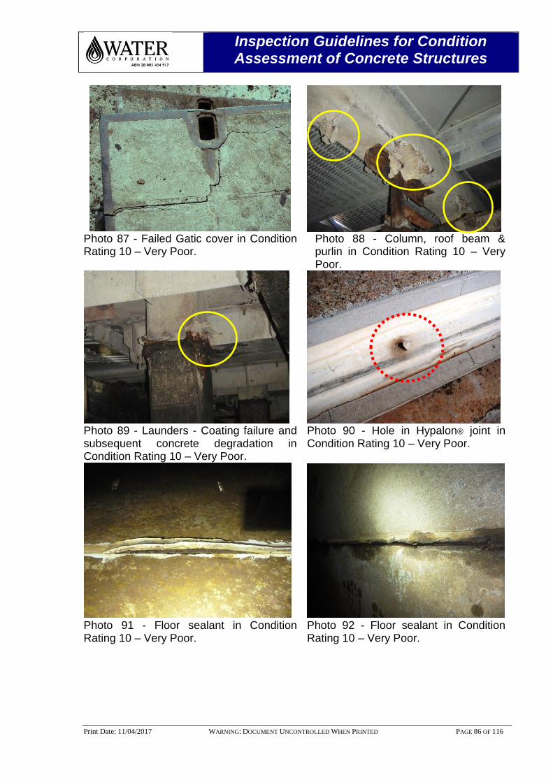
Inspection Guidelines for Condition Assessment of Concrete Structures
Print Date: 11/04/2017 WARNING: DOCUMENT UNCONTROLLED WHEN PRINTED PAGE 86 OF 116
Photo 87 - Failed Gatic cover in Condition Rating 10 – Very Poor.
Photo 88 - Column, roof beam & purlin in Condition Rating 10 – Very Poor.
Photo 89 - Launders - Coating failure and subsequent concrete degradation in Condition Rating 10 – Very Poor.
Photo 90 - Hole in Hypalon® joint in Condition Rating 10 – Very Poor.
Photo 91 - Floor sealant in Condition Rating 10 – Very Poor.
Photo 92 - Floor sealant in Condition Rating 10 – Very Poor.
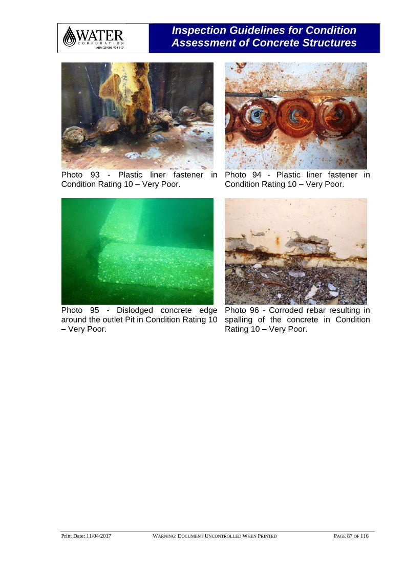
Inspection Guidelines for Condition Assessment of Concrete Structures
Print Date: 11/04/2017 WARNING: DOCUMENT UNCONTROLLED WHEN PRINTED PAGE 87 OF 116
Photo 93 - Plastic liner fastener in Condition Rating 10 – Very Poor.
Photo 94 - Plastic liner fastener in Condition Rating 10 – Very Poor.
Photo 95 - Dislodged concrete edge around the outlet Pit in Condition Rating 10 – Very Poor.
Photo 96 - Corroded rebar resulting in spalling of the concrete in Condition Rating 10 – Very Poor.
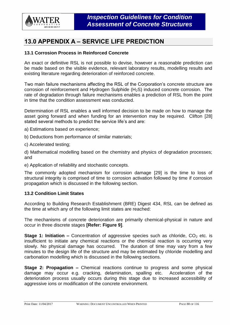
Inspection Guidelines for Condition Assessment of Concrete Structures
Print Date: 11/04/2017 WARNING: DOCUMENT UNCONTROLLED WHEN PRINTED PAGE 88 OF 116
13.0 APPENDIX A – SERVICE LIFE PREDICTION
13.1 Corrosion Process in Reinforced Concrete
An exact or definitive RSL is not possible to devise, however a reasonable prediction can be made based on the visible evidence, relevant laboratory results, modelling results and existing literature regarding deterioration of reinforced concrete. Two main failure mechanisms affecting the RSL of the Corporation’s concrete structure are corrosion of reinforcement and Hydrogen Sulphide (H2S) induced concrete corrosion. The rate of degradation through failure mechanisms enables a prediction of RSL from the point in time that the condition assessment was conducted. Determination of RSL enables a well informed decision to be made on how to manage the asset going forward and when funding for an intervention may be required. Clifton [28] stated several methods to predict the service life’s and are:
a) Estimations based on experience;
b) Deductions from performance of similar materials;
c) Accelerated testing;
d) Mathematical modelling based on the chemistry and physics of degradation processes; and
e) Application of reliability and stochastic concepts.
The commonly adopted mechanism for corrosion damage [29] is the time to loss of structural integrity is comprised of time to corrosion activation followed by time if corrosion propagation which is discussed in the following section.
13.2 Condition Limit States
According to Building Research Establishment (BRE) Digest 434, RSL can be defined as the time at which any of the following limit states are reached: The mechanisms of concrete deterioration are primarily chemical-physical in nature and occur in three discrete stages [Refer: Figure 9]. Stage 1: Initiation – Concentration of aggressive species such as chloride, CO2 etc. is insufficient to initiate any chemical reactions or the chemical reaction is occurring very slowly. No physical damage has occurred. The duration of time may vary from a few minutes to the design life of the structure and may be estimated by chloride modelling and carbonation modelling which is discussed in the following sections. Stage 2: Propagation – Chemical reactions continue to progress and some physical damage may occur e.g. cracking, delamination, spalling etc. Acceleration of the deterioration process usually occurs during this stage due to increased accessibility of aggressive ions or modification of the concrete environment.
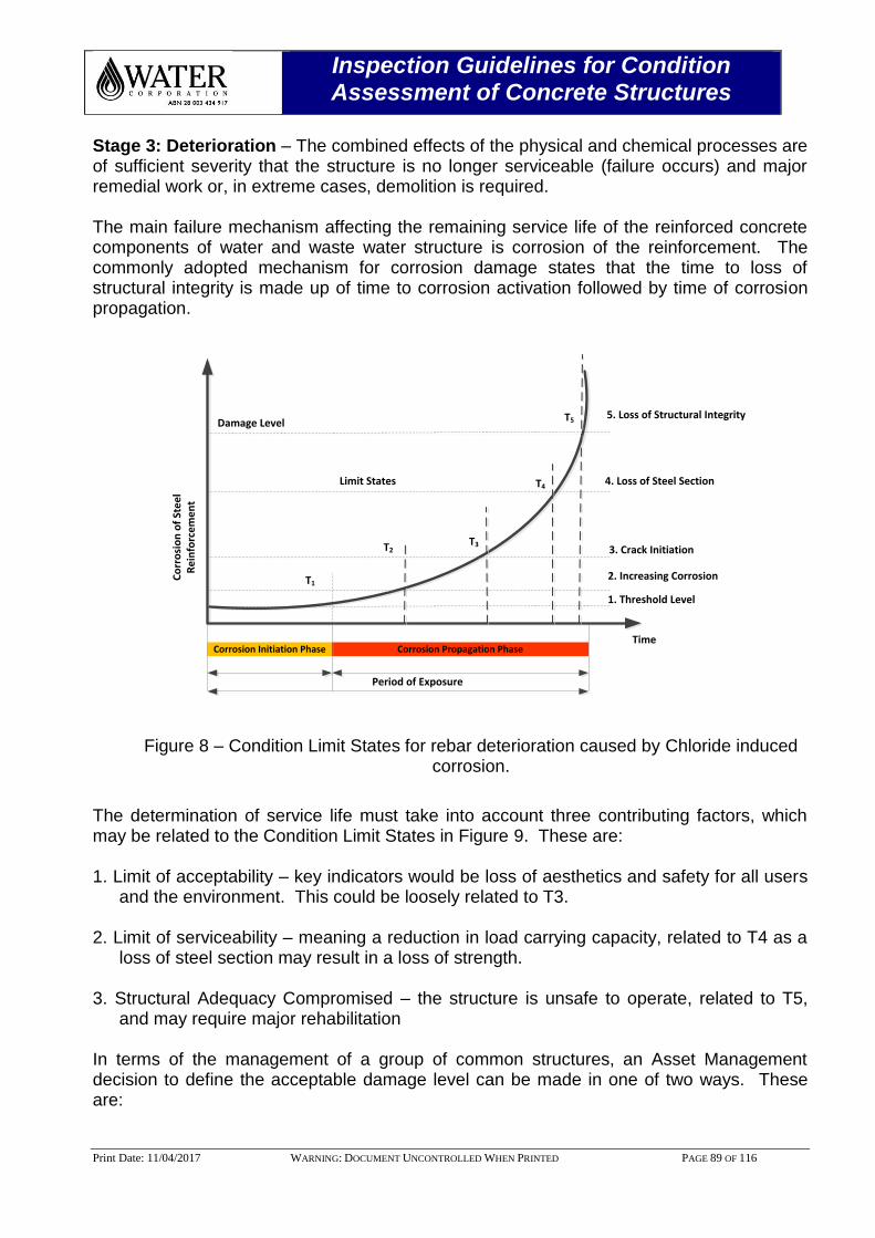
Inspection Guidelines for Condition Assessment of Concrete Structures
Print Date: 11/04/2017 WARNING: DOCUMENT UNCONTROLLED WHEN PRINTED PAGE 89 OF 116
Stage 3: Deterioration – The combined effects of the physical and chemical processes are of sufficient severity that the structure is no longer serviceable (failure occurs) and major remedial work or, in extreme cases, demolition is required. The main failure mechanism affecting the remaining service life of the reinforced concrete components of water and waste water structure is corrosion of the reinforcement. The commonly adopted mechanism for corrosion damage states that the time to loss of structural integrity is made up of time to corrosion activation followed by time of corrosion propagation.
Corrosion Initiation Phase Corrosion Propagation Phase
Damage Level
Period of Exposure
Time
Co
rro
sio
n o
f St
ee
l R
ein
forc
em
en
t
5. Loss of Structural Integrity
4. Loss of Steel Section
3. Crack Initiation
2. Increasing Corrosion
1. Threshold Level
Limit States
T1
T2T3
T4
T5
Figure 8 – Condition Limit States for rebar deterioration caused by Chloride induced corrosion.
The determination of service life must take into account three contributing factors, which may be related to the Condition Limit States in Figure 9. These are: 1. Limit of acceptability – key indicators would be loss of aesthetics and safety for all users
and the environment. This could be loosely related to T3. 2. Limit of serviceability – meaning a reduction in load carrying capacity, related to T4 as a
loss of steel section may result in a loss of strength. 3. Structural Adequacy Compromised – the structure is unsafe to operate, related to T5,
and may require major rehabilitation In terms of the management of a group of common structures, an Asset Management decision to define the acceptable damage level can be made in one of two ways. These are:
Inspection Guidelines for Condition Assessment of Concrete Structures
Print Date: 11/04/2017 WARNING: DOCUMENT UNCONTROLLED WHEN PRINTED PAGE 90 OF 116
Generic definition – This identifies generic condition state limits for all structures, and if the damage level is at or beyond certain condition state limits, then either intervention is required, or the service life has been compromised.
Structure-by-Structure definition – This defines the condition state limit for both end of service life and intervention based on structure specific requirements.
The Consultant carrying out the Level 3 Inspection should consult with the AMB to determine an appropriate damage level for the structures before it either requires intervention, or is deemed to have reached its service life.
13.3 Initiation Phase
The initiation of corrosion of the first layer of reinforcing steel (time to T1) due to chloride ingress or carbonation may be estimated by chloride modelling and carbonation modelling, as discussed in Section 14.5 and 14.6 respectively.
13.4 Corrosion Propagation Phase
Sometime after T1, stresses induced by the expansion of corrosion products will lead to fracture of concrete (cracking, delamination, spalling), loss of ultimate strength, loss of bond between steel and concrete and ultimately loss of structural capacity. This deterioration is primarily dependant on the rate of corrosion, fracture properties of concrete, reinforcement area, size and spacing and cover depth. The time after T1 depends on the corrosion propagation rate, which is often difficult to estimate. In situ corrosion rate tests such as Linear Polarisation Resistance (LPR) or Galvanostatic pulse corrosion rate may be used to determine the rate of corrosion; however these tests have limitations and only provide an approximate estimate of corrosion rate at the time of the test. Measurement of actual corrosion loss can also provide an estimate of corrosion rate, although this may tend to over-estimate the general rate. Other site measurements that assist in estimating probable propagation time include concrete resistivity, half-cell potential maps and visual inspections of the reinforcement at breakouts. From literature and based on industry experience, the period between activation and first significant crack (between T1 and T3 in Figure 8) is typically of the order 10 to 20 years at high corrosion rates up to 10 microns/year as stated in BRE 43 for crack widths up to 0.3 mm. The time to cracking is longer for small diameter bars due to a smaller volume of rust product being formed, and where cover is greater. The significance of cracking depends on the structural component.
13.4.1 Prediction of RSL for Chloride Induced Corrosion
The predicted service life, however, would be the addition of time to T1 and time from T1 to the designated condition limit state for end of service life (whether this is T3, T4 or T5). With current materials condition, Renewals Planning, AMB, will estimate the service life as follows:
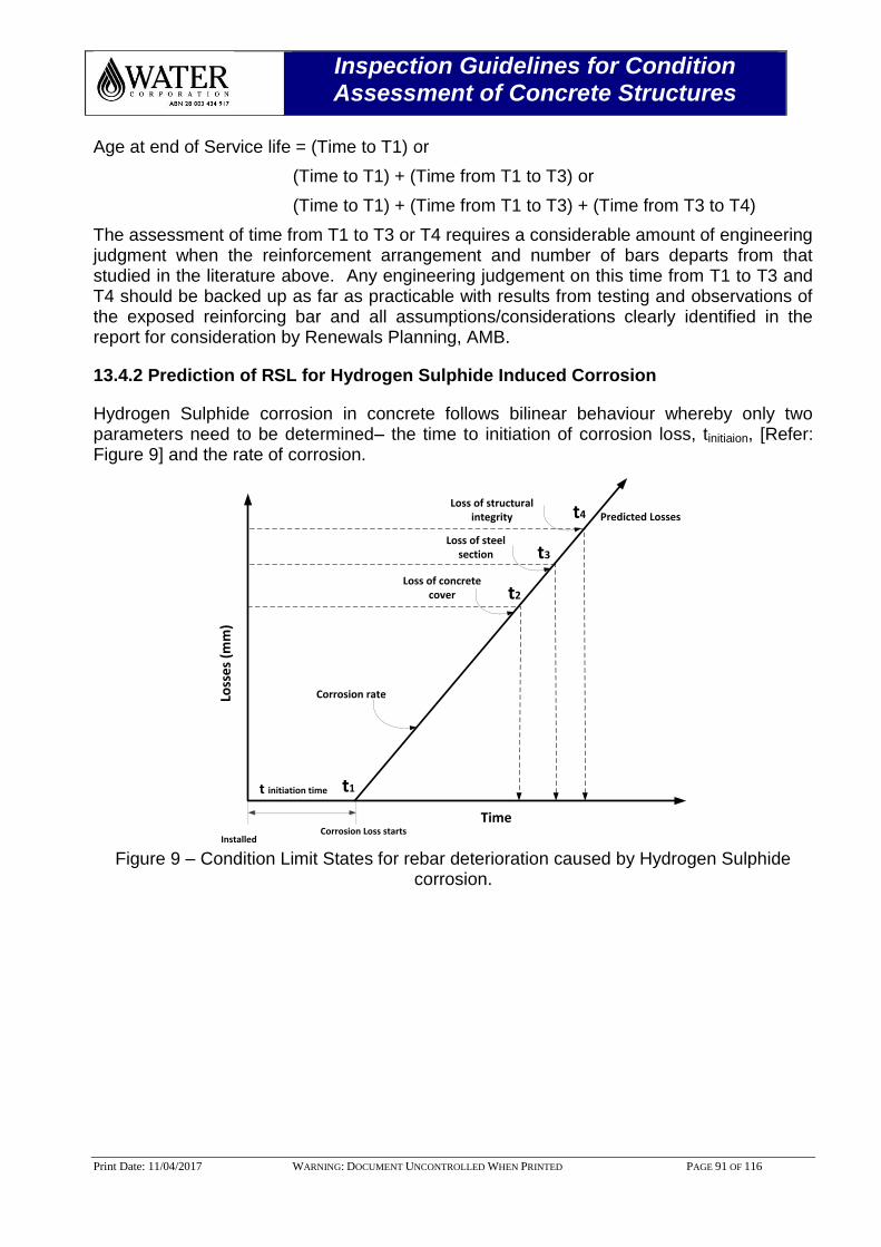
Inspection Guidelines for Condition Assessment of Concrete Structures
Print Date: 11/04/2017 WARNING: DOCUMENT UNCONTROLLED WHEN PRINTED PAGE 91 OF 116
Age at end of Service life = (Time to T1) or
(Time to T1) + (Time from T1 to T3) or
(Time to T1) + (Time from T1 to T3) + (Time from T3 to T4)
The assessment of time from T1 to T3 or T4 requires a considerable amount of engineering judgment when the reinforcement arrangement and number of bars departs from that studied in the literature above. Any engineering judgement on this time from T1 to T3 and T4 should be backed up as far as practicable with results from testing and observations of the exposed reinforcing bar and all assumptions/considerations clearly identified in the report for consideration by Renewals Planning, AMB.
13.4.2 Prediction of RSL for Hydrogen Sulphide Induced Corrosion
Hydrogen Sulphide corrosion in concrete follows bilinear behaviour whereby only two parameters need to be determined– the time to initiation of corrosion loss, tinitiaion, [Refer: Figure 9] and the rate of corrosion.
Corrosion Loss starts
Loss
es
(mm
)
t initiation time
Installed
Time
Corrosion rate
Predicted Losses
t2
t3
t4
Loss of steel section
Loss of structural integrity
Loss of concrete cover
t1
Figure 9 – Condition Limit States for rebar deterioration caused by Hydrogen Sulphide
corrosion.
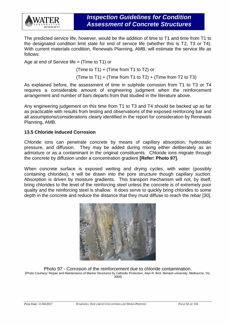
Inspection Guidelines for Condition Assessment of Concrete Structures
Print Date: 11/04/2017 WARNING: DOCUMENT UNCONTROLLED WHEN PRINTED PAGE 92 OF 116
The predicted service life, however, would be the addition of time to T1 and time from T1 to the designated condition limit state for end of service life (whether this is T2, T3 or T4). With current materials condition, Renewals Planning, AMB, will estimate the service life as follows:
Age at end of Service life = (Time to T1) or
(Time to T1) + (Time from T1 to T2) or
(Time to T1) + (Time from T1 to T2) + (Time from T2 to T3)
As explained before, the assessment of time in sulphide corrosion from T1 to T3 or T4 requires a considerable amount of engineering judgment when the reinforcement arrangement and number of bars departs from that studied in the literature above. Any engineering judgement on this time from T1 to T3 and T4 should be backed up as far as practicable with results from testing and observations of the exposed reinforcing bar and all assumptions/considerations clearly identified in the report for consideration by Renewals Planning, AMB.
13.5 Chloride Induced Corrosion
Chloride ions can penetrate concrete by means of capillary absorption, hydrostatic pressure, and diffusion. They may be added during mixing either deliberately as an admixture or as a contaminant in the original constituents. Chloride ions migrate through the concrete by diffusion under a concentration gradient [Refer: Photo 97]. When concrete surface is exposed wetting and drying cycles, with water (possibly containing chlorides), it will be drawn into the pore structure though capillary suction. Absorption is driven by moisture gradients. This transport mechanism will not, by itself, bring chlorides to the level of the reinforcing steel unless the concrete is of extremely poor quality and the reinforcing steel is shallow. It does serve to quickly bring chlorides to some depth in the concrete and reduce the distance that they must diffuse to reach the rebar [30].
Photo 97 - Corrosion of the reinforcement due to chloride contamination. [Photo Courtesy: Repair and Maintenance of Marine Structures by Cathodic Protection, Alan R. Bird, Monash university, Melbourne, Vic,
3000]

Inspection Guidelines for Condition Assessment of Concrete Structures
Print Date: 11/04/2017 WARNING: DOCUMENT UNCONTROLLED WHEN PRINTED PAGE 93 OF 116
Once chloride ions have reached the reinforcement in sufficient quantities they will depassivate the embedded steel rebar by breaking down the protective oxide layer normally maintained by the alkaline environment. The concentration of chloride ions required to initiate and maintain corrosion is dependent upon the alkalinity and it has been shown that there is an almost linear relationship between hydroxyl ion concentration and the respective threshold level of chloride [31]. Figure 10 shows the passive film breakdown and concrete failure due to the ingress of chloride ions.
Iron
Concrete
2H2O + O2 + 4e- → 4OH-
Anode
2Fe → 2Fe2+ + 4e-
4e-
Cathode
2Fe(OH)2Rust
2Fe(OH)2Rust
H2O
Surface
O2 Chloride, Cl2- Chloride, Cl2
-
2Fe2+2Fe2+
Cracking and spalling of the concrete cover
Build up of corrosion products resulting in volume expansion
Ingress of corrosive species into porous concrete
4e-
Figure 10 – Passive film breakdown and concrete failure.
Chloride diffusion is the transfer of mass by random motion of the free chloride ions in the pore solution resulting from regions of higher concentration to regions of lower concentration [32, 33].
Since the ingress of chloride ions into concrete involves inward movement of water containing chloride ions through its pore structure, the prediction of chloride ion penetration into concrete is usually obtained using Fick’s second law of diffusion.
Theoretically, the initiation time (t) can be estimated by Fick’s second law of diffusion:
𝐶𝑥,𝑡 = 𝐶𝑖 + (𝐶𝑠 − 𝐶𝑖) ∗ (1 − 𝑒𝑟𝑓 [𝑥
2√𝐷𝑡])
Where,
D = chloride diffusion coefficient;
Ci = initial background chloride concentration of concrete and is usually negligible;
CS = surface chloride content;
x = depth in concrete;
C(x,t) = chloride concentration at depth x after time t; and
erf = complement of the error function.
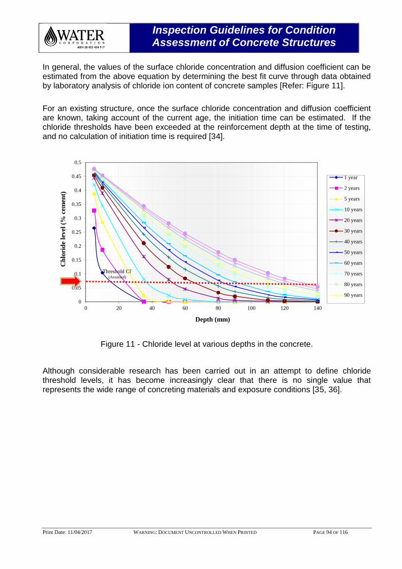
Inspection Guidelines for Condition Assessment of Concrete Structures
Print Date: 11/04/2017 WARNING: DOCUMENT UNCONTROLLED WHEN PRINTED PAGE 94 OF 116
In general, the values of the surface chloride concentration and diffusion coefficient can be estimated from the above equation by determining the best fit curve through data obtained by laboratory analysis of chloride ion content of concrete samples [Refer: Figure 11].
For an existing structure, once the surface chloride concentration and diffusion coefficient are known, taking account of the current age, the initiation time can be estimated. If the chloride thresholds have been exceeded at the reinforcement depth at the time of testing, and no calculation of initiation time is required [34].
Figure 11 - Chloride level at various depths in the concrete.
Although considerable research has been carried out in an attempt to define chloride threshold levels, it has become increasingly clear that there is no single value that represents the wide range of concreting materials and exposure conditions [35, 36].
0
0.05
0.1
0.15
0.2
0.25
0.3
0.35
0.4
0.45
0.5
0 20 40 60 80 100 120 140
Ch
lori
de
lev
el (
% c
em
ent)
Depth (mm)
1 year
2 years
5 years
10 years
20 years
30 years
40 years
50 years
60 years
70 years
80 years
90 years
Threshold Cl-
(Assumed)

Inspection Guidelines for Condition Assessment of Concrete Structures
Print Date: 11/04/2017 WARNING: DOCUMENT UNCONTROLLED WHEN PRINTED PAGE 95 OF 116
13.6 Carbonation Induced Corrosion
Carbonation is the result of the interaction of carbon dioxide gas in the atmosphere with the alkaline hydroxides in the concrete. Like many other gases carbon dioxide dissolved in water to form Carbonic acid. Unlike most other acids, the Carbonic Acid (H2CO3) does not attack the cement paste, but just neutralizes the alkalis in the pore water, mainly forming calcium carbonate (CaCO3)
that lines the pores:
CO2 + H2O H2CO3
H2CO3 + Ca(OH)2 CaCO3 + 2H2O
Calcium Hydroxide (Ca(OH)2) in the concrete pores maintains the alkalinity and hence the corrosion resistance of the rebar. However, after all the locally available Calcium Hydroxide reacts with Carbonic Acid, precipitating the Calcium Carbonate and allowing the pH to fall to a level where steel will corrode [Refer: Photo 98].
Iron
Concrete
2H2O + O2 + 4e- → 4OH-
Anode
2Fe → 2Fe2+ + 4e-
4e-4e-
Cathode
2Fe(OH)2Rust
2Fe(OH)2Rust
H2O
Surface
2Fe2+
2Fe2+
Passive film is dissolved by carbonation of concrete
Build up of corrosion products resulting in volume expansion
Rebar is protected by high alkalinity of concrete from corrosion
CO2 Diffusion of Carbon di oxide,CO2Diffusion of Carbon di oxide,
Figure 12 – Carbonation principle.
The depth of carbonation in a structure can be quite easily established by the use of phenolphthalein indicator on freshly exposed material. The distinctive colour change, from deep pink in unaffected concrete to clear in the carbonated region, is sufficiently accurate for most practical purposes provided a number of measurements are obtained to allow for local variations [Refer: Photo 99].
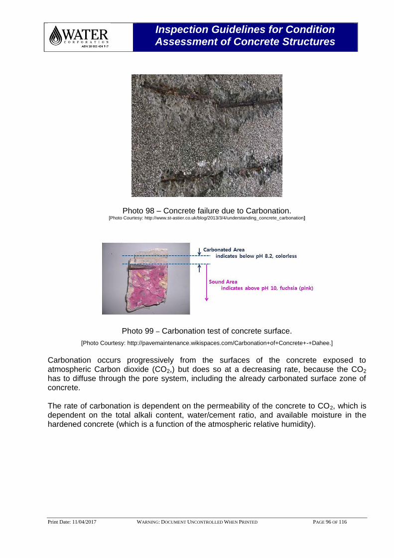
Inspection Guidelines for Condition Assessment of Concrete Structures
Print Date: 11/04/2017 WARNING: DOCUMENT UNCONTROLLED WHEN PRINTED PAGE 96 OF 116
Photo 98 – Concrete failure due to Carbonation. [Photo Courtesy: http://www.st-astier.co.uk/blog/2013/3/4/understanding_concrete_carbonation]
Photo 99 – Carbonation test of concrete surface.
[Photo Courtesy: http://pavemaintenance.wikispaces.com/Carbonation+of+Concrete+-+Dahee.]
Carbonation occurs progressively from the surfaces of the concrete exposed to atmospheric Carbon dioxide (CO2,) but does so at a decreasing rate, because the CO2 has to diffuse through the pore system, including the already carbonated surface zone of concrete. The rate of carbonation is dependent on the permeability of the concrete to CO2, which is dependent on the total alkali content, water/cement ratio, and available moisture in the hardened concrete (which is a function of the atmospheric relative humidity).
Inspection Guidelines for Condition Assessment of Concrete Structures
Print Date: 11/04/2017 WARNING: DOCUMENT UNCONTROLLED WHEN PRINTED PAGE 97 OF 116
The rate of reaction of CO2 with concrete is closely related to the relative humidity of the environment in which the structure resides. Permanently saturated environments and buried structures that are not in direct contact with atmospheric carbon dioxide are not at significant risk of carbonation, and thus are not covered by the model. The optimum effective relative humidity (RH) in the concrete for carbonation is 50-60%. At a relative humidity above 95% the diffusion of carbon dioxide is very slow because of the reduced space for gaseous diffusion in water-filled pores. At a relative humidity below 50% the supply of water to dissolve the carbon dioxide is limited and the rate of attack slows.
A generalised carbonation model involving a relationship between depth of carbonation x1, time of exposure t1, and carbonation coefficient DCarb is used for carbonation penetration predictions. This relationship is as follows:
x1 = DCarb √𝑡1
The actual depth of the concrete cover that has carbonated is determined by phenolphthalein indicator. The distinctive colour change, from deep pink in unaffected concrete to clear in the carbonated region, is sufficiently accurate for most practical purposes provided a number of measurements are obtained to allow for local variations. Using this depth and with the age of the concrete, the above equation can be used to determine the DCarb. The above equation is then used again to determine an estimate of the length of time needed for the whole cover concrete to become carbonated and leave the reinforcement in an environment where corrosion can commence. Currently, Water Corporation adopts Concrete Structures Remaining Service Life (CSRL) tool to determine the depth of carbonation on the concrete structure. The carbonation model is based on Building Research Establishment (BRE). The time at which the carbonation will reach to the reinforcement cover can be obtained from the above Figure 13. For example, carbonation reaches a depth of 15 mm when the concrete is at an age of approximately 70 years.
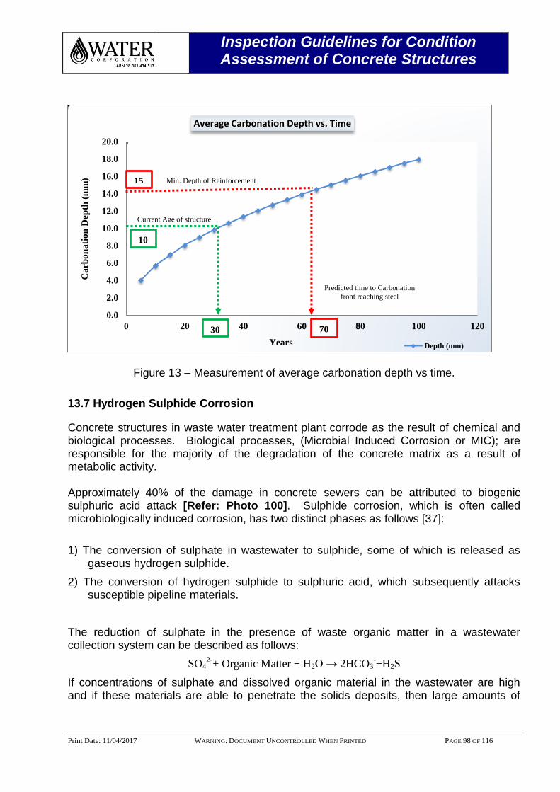
Inspection Guidelines for Condition Assessment of Concrete Structures
Print Date: 11/04/2017 WARNING: DOCUMENT UNCONTROLLED WHEN PRINTED PAGE 98 OF 116
Figure 13 – Measurement of average carbonation depth vs time.
13.7 Hydrogen Sulphide Corrosion
Concrete structures in waste water treatment plant corrode as the result of chemical and biological processes. Biological processes, (Microbial Induced Corrosion or MIC); are responsible for the majority of the degradation of the concrete matrix as a result of metabolic activity. Approximately 40% of the damage in concrete sewers can be attributed to biogenic sulphuric acid attack [Refer: Photo 100]. Sulphide corrosion, which is often called microbiologically induced corrosion, has two distinct phases as follows [37]:
1) The conversion of sulphate in wastewater to sulphide, some of which is released as gaseous hydrogen sulphide.
2) The conversion of hydrogen sulphide to sulphuric acid, which subsequently attacks susceptible pipeline materials.
The reduction of sulphate in the presence of waste organic matter in a wastewater collection system can be described as follows:
SO42-
+ Organic Matter + H2O → 2HCO3-+H2S
If concentrations of sulphate and dissolved organic material in the wastewater are high and if these materials are able to penetrate the solids deposits, then large amounts of
0.0
2.0
4.0
6.0
8.0
10.0
12.0
14.0
16.0
18.0
20.0
0 20 40 60 80 100 120
Ca
rbo
na
tio
n D
ep
th (
mm
)
Years
Average Carbonation Depth vs. Time
Depth (mm)
Predicted time to Carbonation front reaching steel
Min. Depth of Reinforcement
Current Age of structure
70 30
10
15
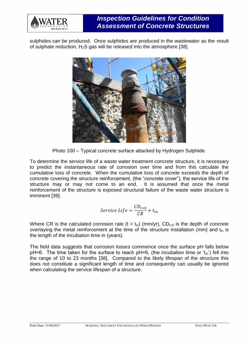
Inspection Guidelines for Condition Assessment of Concrete Structures
Print Date: 11/04/2017 WARNING: DOCUMENT UNCONTROLLED WHEN PRINTED PAGE 99 OF 116
sulphides can be produced. Once sulphides are produced in the wastewater as the result of sulphate reduction, H2S gas will be released into the atmosphere [38].
Photo 100 – Typical concrete surface attacked by Hydrogen Sulphide.
To determine the service life of a waste water treatment concrete structure, it is necessary to predict the instantaneous rate of corrosion over time and from this calculate the cumulative loss of concrete. When the cumulative loss of concrete exceeds the depth of concrete covering the structure reinforcement, (the “concrete cover”), the service life of the structure may or may not come to an end. It is assumed that once the metal reinforcement of the structure is exposed structural failure of the waste water structure is imminent [39].
𝑆𝑒𝑟𝑣𝑖𝑐𝑒 𝐿𝑖𝑓𝑒 =𝐶𝐷𝑡=0
𝐶𝑅+ 𝑡𝑖𝑛
Where CR is the calculated corrosion rate (t > tin) (mm/yr), CDt=0 is the depth of concrete overlaying the metal reinforcement at the time of the structure installation (mm) and tin is the length of the incubation time in (years). The field data suggests that corrosion losses commence once the surface pH falls below pH=6. The time taken for the surface to reach pH=6, (the incubation time or ‘t in’) fell into the range of 10 to 23 months [38]. Compared to the likely lifespan of the structure this does not constitute a significant length of time and consequently can usually be ignored when calculating the service lifespan of a structure.
Inspection Guidelines for Condition Assessment of Concrete Structures
Print Date: 11/04/2017 WARNING: DOCUMENT UNCONTROLLED WHEN PRINTED PAGE 100 OF 116
The impact of the initiation or incubation period, tin, would however be more significant if corrosion predictions for a limited period of a structure’s service life are required (for the next decade for example). In these circumstances it would be of benefit to be able to estimate the value of tin for a given site from the available environmental data. Above pH=6 it is assumed that there is little biological activity on the concrete surface, hence corrosion results from the action of H2S dissolves into the pore water. Once dissolved in the pore water the HS ion formed can undergo a series of chemical (i.e. abiotic) reaction to form a variety of oxidated sulphur species. If temperature, humidity and H2S concentration are known (or can be estimated) tin can be estimated via:
𝑡𝑖𝑛(𝑦𝑒𝑎𝑟𝑠) = 1.24 𝑥 10−10𝑥 [𝐻2𝑆]−0.8 𝑥 (0.0955 𝑥 𝑅𝐻% − 9.8044)
(1 − 0.01245 𝑥 𝑅𝐻%) 𝑥 𝑒((56,000/(8.314 𝑥 (𝑇+273)) + 0.91
If only H2S concentration in the gas phase is known tin can be estimated via:
𝑡𝑖𝑛(𝑦𝑒𝑎𝑟𝑠) = 1.62 − 0.083 𝑥 𝑙𝑛[𝐻2𝑆]

Inspection Guidelines for Condition Assessment of Concrete Structures
Print Date: 11/04/2017 WARNING: DOCUMENT UNCONTROLLED WHEN PRINTED PAGE 101 OF 116
14.0 APPENDIX B – LEVEL 1 INSPECTION TEMPLATE FOR TANKS
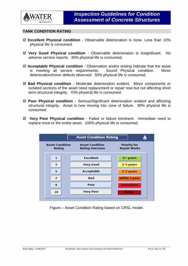
Inspection Guidelines for Condition Assessment of Concrete Structures
Print Date: 11/04/2017 WARNING: DOCUMENT UNCONTROLLED WHEN PRINTED PAGE 102 OF 116
TANK CONDITION RATING
Excellent Physical condition - Observable deterioration is none. Less than 10% physical life is consumed.
Very Good Physical condition - Observable deterioration is insignificant. No
adverse service reports. 30% physical life is consumed. Acceptable Physical condition - Observation and/or testing indicate that the asset
is meeting all service requirements. Sound Physical condition. Minor deterioration/minor defects observed. 50% physical life is consumed.
Bad Physical condition - Moderate deterioration evident. Minor components or
isolated sections of the asset need replacement or repair now but not affecting short term structural integrity. 70% physical life is consumed.
Poor Physical condition - Serious/Significant deterioration evident and affecting
structural integrity. Asset is now moving into zone of failure. 90% physical life is consumed.
Very Poor Physical condition - Failed or failure imminent. Immediate need to
replace most or the entire asset. 100% physical life is consumed.
Figure – Asset Condition Rating based on CRSL model.
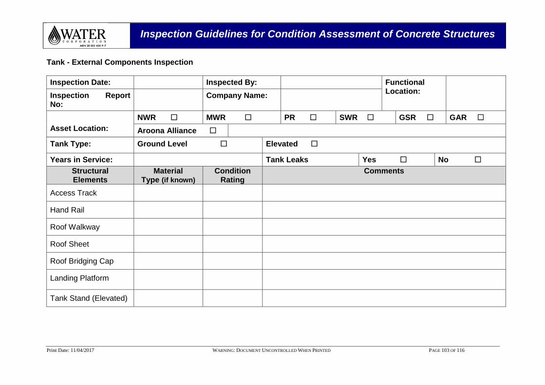
Inspection Guidelines for Condition Assessment of Concrete Structures
Print Date: 11/04/2017 WARNING: DOCUMENT UNCONTROLLED WHEN PRINTED PAGE 103 OF 116
Tank - External Components Inspection
Inspection Date: Inspected By: Functional Location:
Inspection Report No:
Company Name:
Asset Location:
NWR MWR PR SWR GSR GAR
Aroona Alliance
Tank Type: Ground Level Elevated
Years in Service: Tank Leaks Yes No
Structural Elements
Material Type (if known)
Condition Rating
Comments
Access Track
Hand Rail
Roof Walkway
Roof Sheet
Roof Bridging Cap
Landing Platform
Tank Stand (Elevated)
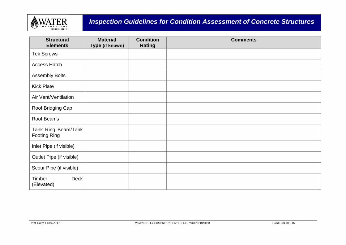
Inspection Guidelines for Condition Assessment of Concrete Structures
Print Date: 11/04/2017 WARNING: DOCUMENT UNCONTROLLED WHEN PRINTED PAGE 104 OF 116
Structural Elements
Material Type (if known)
Condition Rating
Comments
Tek Screws
Access Hatch
Assembly Bolts
Kick Plate
Air Vent/Ventilation
Roof Bridging Cap
Roof Beams
Tank Ring Beam/Tank Footing Ring
Inlet Pipe (if visible)
Outlet Pipe (if visible)
Scour Pipe (if visible)
Timber Deck (Elevated)
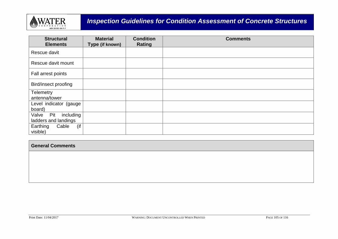
Inspection Guidelines for Condition Assessment of Concrete Structures
Print Date: 11/04/2017 WARNING: DOCUMENT UNCONTROLLED WHEN PRINTED PAGE 105 OF 116
Structural Elements
Material Type (if known)
Condition Rating
Comments
Rescue davit
Rescue davit mount
Fall arrest points
Bird/insect proofing
Telemetry antenna/tower
Level indicator (gauge board)
Valve Pit including ladders and landings
Earthing Cable (if visible)
General Comments
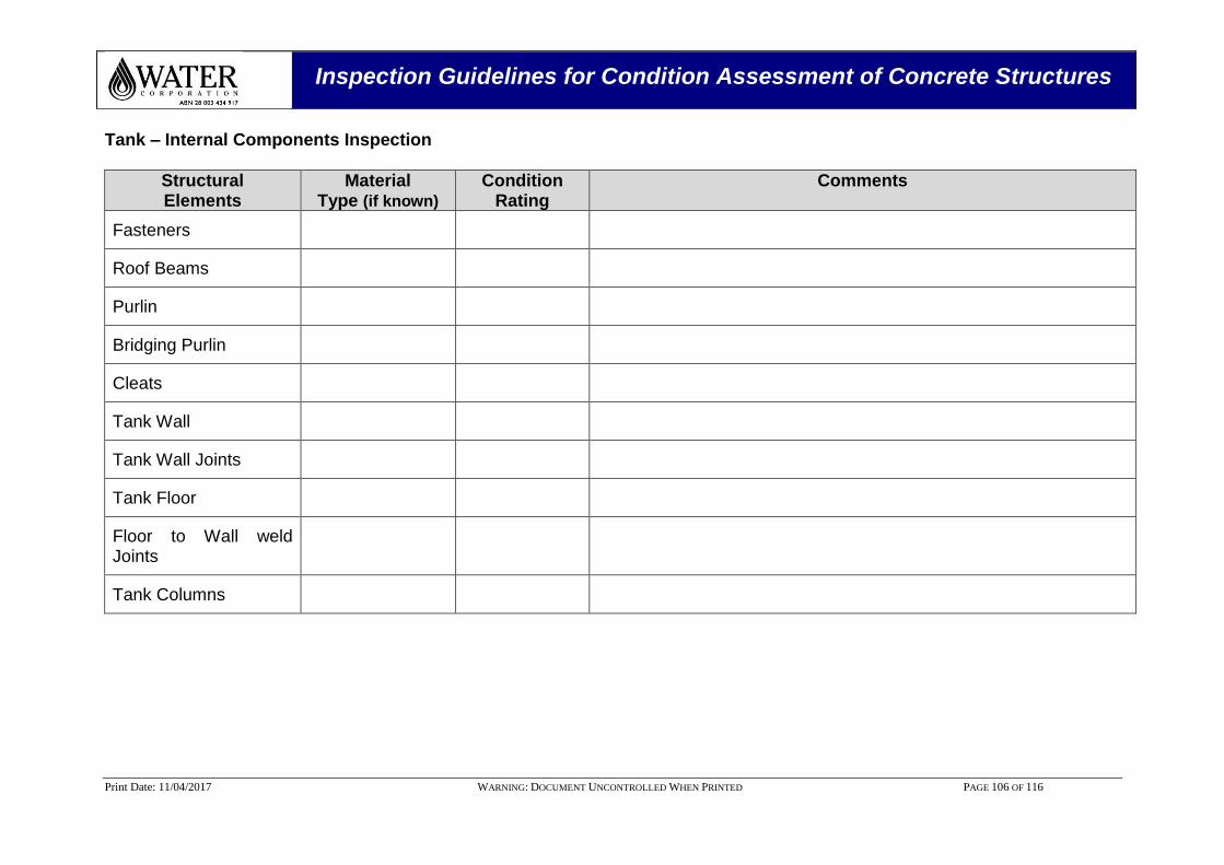
Inspection Guidelines for Condition Assessment of Concrete Structures
Print Date: 11/04/2017 WARNING: DOCUMENT UNCONTROLLED WHEN PRINTED PAGE 106 OF 116
Tank – Internal Components Inspection
Structural Elements
Material Type (if known)
Condition Rating
Comments
Fasteners
Roof Beams
Purlin
Bridging Purlin
Cleats
Tank Wall
Tank Wall Joints
Tank Floor
Floor to Wall weld Joints
Tank Columns
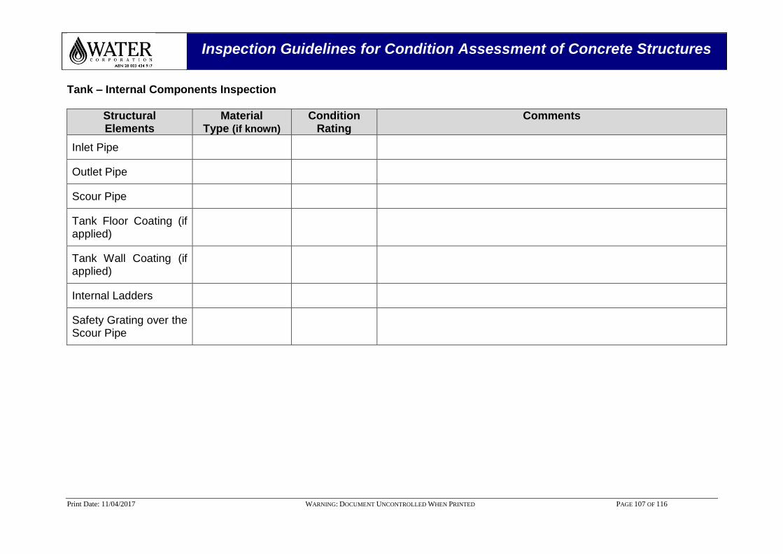
Inspection Guidelines for Condition Assessment of Concrete Structures
Print Date: 11/04/2017 WARNING: DOCUMENT UNCONTROLLED WHEN PRINTED PAGE 107 OF 116
Tank – Internal Components Inspection
Structural Elements
Material Type (if known)
Condition Rating
Comments
Inlet Pipe
Outlet Pipe
Scour Pipe
Tank Floor Coating (if applied)
Tank Wall Coating (if applied)
Internal Ladders
Safety Grating over the Scour Pipe
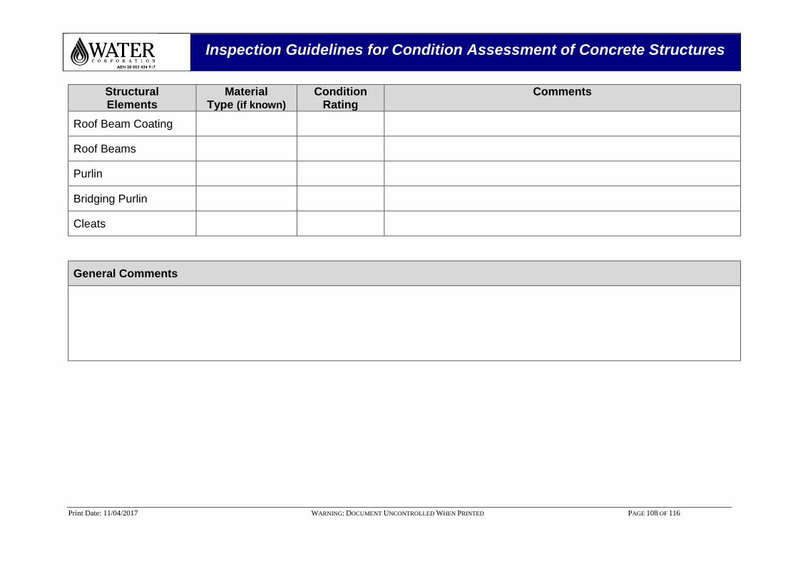
Inspection Guidelines for Condition Assessment of Concrete Structures
Print Date: 11/04/2017 WARNING: DOCUMENT UNCONTROLLED WHEN PRINTED PAGE 108 OF 116
Structural Elements
Material Type (if known)
Condition Rating
Comments
Roof Beam Coating
Roof Beams
Purlin
Bridging Purlin
Cleats
General Comments
Inspection Guidelines for Condition Assessment of Concrete Structures
Print Date: 11/04/2017 WARNING: DOCUMENT UNCONTROLLED WHEN PRINTED PAGE 109 OF 116
15.0 APPENDIX C - LEVEL 2 FORMALISED INSPECTION TEMPLATE
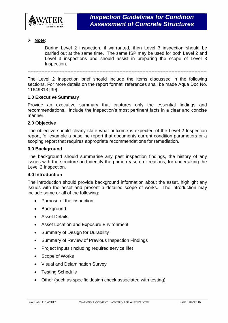
Inspection Guidelines for Condition Assessment of Concrete Structures
Print Date: 11/04/2017 WARNING: DOCUMENT UNCONTROLLED WHEN PRINTED PAGE 110 OF 116
Note:
During Level 2 inspection, if warranted, then Level 3 inspection should be carried out at the same time. The same ISP may be used for both Level 2 and Level 3 inspections and should assist in preparing the scope of Level 3 Inspection.
---------------------------------------------------------------------------------------------------------------------
The Level 2 Inspection brief should include the items discussed in the following sections. For more details on the report format, references shall be made Aqua Doc No. 11649813 [39].
1.0 Executive Summary
Provide an executive summary that captures only the essential findings and recommendations. Include the inspection’s most pertinent facts in a clear and concise manner.
2.0 Objective
The objective should clearly state what outcome is expected of the Level 2 Inspection report, for example a baseline report that documents current condition parameters or a scoping report that requires appropriate recommendations for remediation.
3.0 Background
The background should summarise any past inspection findings, the history of any issues with the structure and identify the prime reason, or reasons, for undertaking the Level 2 Inspection.
4.0 Introduction
The introduction should provide background information about the asset, highlight any issues with the asset and present a detailed scope of works. The introduction may include some or all of the following:
Purpose of the inspection
Background
Asset Details
Asset Location and Exposure Environment
Summary of Design for Durability
Summary of Review of Previous Inspection Findings
Project Inputs (including required service life)
Scope of Works
Visual and Delamination Survey
Testing Schedule
Other (such as specific design check associated with testing)
Inspection Guidelines for Condition Assessment of Concrete Structures
Print Date: 11/04/2017 WARNING: DOCUMENT UNCONTROLLED WHEN PRINTED PAGE 111 OF 116
5.0 Formalised Inspection Results
This section is to present investigation results for each test undertaken. Full inspection data should be included in Appendices. This report section should complement, and refer to, these guidelines and only describe test procedures to the extent necessary for the understanding of the report, or where not covered by these guidelines. This section may include some or all of the following:
Visual and Delamination Survey Results
Rebound Hammer
Concrete Breakout
Covermeter Survey
Half-cell Potential Survey
Resistivity Measurements
6.0 Summary of Current Condition
This section shall be clearly set out by asset component in accordance with the design drawing e.g. raker arm, influent well, scum shovel etc.
7.0 Discussion
This section should discuss and recommend the various options for maintenance or remediation. Discussion of investigation results shall be clearly set out by asset component.
8.0 Conclusions and Recommendations
This section should provide condition rating of individual components inspected should be included. The rating shall be in accordance with Figure 1 of this document.
Durability Design Requirements.
Conclusion.
Summary of Recommended Maintenance and Remedial Options.
9.0 Appendices
Appendices are to include any relevant workings, predictions, certificates etc. Typical appendices may include:
Appendix A - Asset Details
Appendix B - Photographs
Appendix C - Inspection and Testing Schedule
Appendix D - On-site Investigation Results
Inspection Guidelines for Condition Assessment of Concrete Structures
Print Date: 11/04/2017 WARNING: DOCUMENT UNCONTROLLED WHEN PRINTED PAGE 112 OF 116
16.0 APPENDIX D - LEVEL 3 – DETAILED INVESTIGATION TEMPLATE
Inspection Guidelines for Condition Assessment of Concrete Structures
Print Date: 11/04/2017 WARNING: DOCUMENT UNCONTROLLED WHEN PRINTED PAGE 113 OF 116
Note:
The Level 3 Inspection brief should include the following items. For more details on the report format, references shall be made Aqua Doc No. 11649813 [39].
---------------------------------------------------------------------------------------------------------------------
1.0 Executive Summary
Provide an executive summary that captures only the essential findings and recommendations. Include the inspection’s most pertinent facts in a clear and concise manner.
2.0 Objective
The objective should clearly state what outcome is expected of the Level 3 Inspection report. For example, a baseline report that documents current condition parameters or a scoping report that requires appropriate recommendations for remediation.
3.0 Background
The background should summarise any past inspection findings, the history of any issues with the structure and identify the prime reason, or reasons, for undertaking the Level 2 Inspection.
4.0 Introduction
The introduction should provide background information about the asset, highlight any issues with the asset and present a detailed scope of works. The introduction may include some or all of the following:
Purpose of the inspection
Background
Asset Details
Asset Location and Exposure Environment
Summary of Design for Durability
Summary of Review of Previous Inspection Findings
Project Inputs (including required service life)
Scope of Works
Visual and Delamination Survey
Testing Schedule
Other (such as specific design check associated with testing)
Inspection Guidelines for Condition Assessment of Concrete Structures
Print Date: 11/04/2017 WARNING: DOCUMENT UNCONTROLLED WHEN PRINTED PAGE 114 OF 116
5.0 Detailed Investigation Results
This section is to present investigation results for each test undertaken. Full inspection data should be included in Appendices. This report section should complement, and refer to, these guidelines and only describe test procedures to the extent necessary for the understanding of the report, or where not covered by these guidelines. All the calculation for the Remaining Service Life (RSL) should be included in the Appendices i.e. how you deduce the RSL. This section may include some or all of the following:
Carbonation Depth and Modelling Results
Chloride Content and Modelling Results
Sulphate Content
Water/Wastewater Analysis
6.0 Summary of Current Condition
This section shall be clearly set out by asset component in accordance with the design drawing e.g. raker arm, influent well, scum shovel etc.
7.0 Discussion
This section should discuss and recommend the various options for maintenance or remediation. Discussion of investigation results shall be clearly set out by asset component
8.0 Conclusions and Recommendations
This section should provide condition rating of individual components inspected should be included. The rating shall be in accordance with Figure 1 of this document.
Durability Design Requirements.
Conclusion
RSL of the components/structures
Summary of Recommended Maintenance and Remedial Options
9.0 Appendices
Appendices are to include any relevant workings, predictions, certificates etc. Typical appendices may include:
Appendix A - Asset Details
Appendix B - Photographs
Appendix C - Inspection and Testing Schedule
Appendix D - On-site Investigation Results
Appendix E - Depth of carbonation Predictions/other predictions
Appendix F - Laboratory Test Certificates
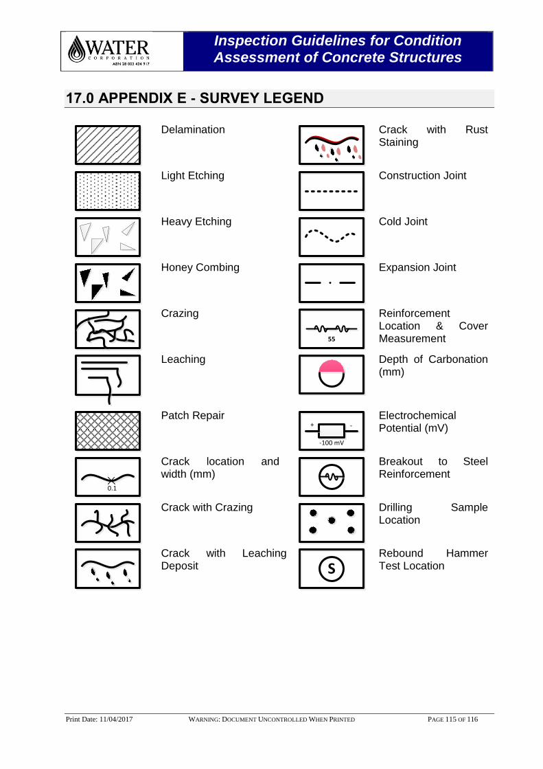
Inspection Guidelines for Condition Assessment of Concrete Structures
Print Date: 11/04/2017 WARNING: DOCUMENT UNCONTROLLED WHEN PRINTED PAGE 115 OF 116
17.0 APPENDIX E - SURVEY LEGEND
Delamination
Crack with Rust Staining
Light Etching
Construction Joint
Heavy Etching
Cold Joint
Honey Combing
Expansion Joint
Crazing
55
Reinforcement Location & Cover Measurement
Leaching
Depth of Carbonation (mm)
Patch Repair + -
-100 mV
Electrochemical Potential (mV)
0.1
Crack location and width (mm)
Breakout to Steel Reinforcement
Crack with Crazing
Drilling Sample Location
Crack with Leaching Deposit S
Rebound Hammer Test Location
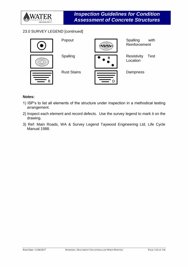
Inspection Guidelines for Condition Assessment of Concrete Structures
Print Date: 11/04/2017 WARNING: DOCUMENT UNCONTROLLED WHEN PRINTED PAGE 116 OF 116
23.0 SURVEY LEGEND [continued]
Popout
Spalling with Reinforcement
Spalling R
Resistivity Test Location
R
Rust Stains
D
Dampness
Notes:
1) ISP’s to list all elements of the structure under inspection in a methodical testing arrangement.
2) Inspect each element and record defects. Use the survey legend to mark it on the drawing.
3) Ref: Main Roads, WA & Survey Legend Taywood Engineering Ltd, Life Cycle Manual 1988.