Embed Size (px)
Citation preview

NORD IMP IANT I P R O D U C T S T U R N K E Y S E R V I C E G L O B A LA P P L I C A T I O N S
Technology for the Precast and Prestressed Concrete Industry
InvertedT and I-BeamsApplications
Inverted T-Beams Inverted I-Beams

SLIPFORMER sf WET CASTING wf
2
INVERTED T AND I-BEAMS
Inverted T and I-Beams are prestressed concrete elements that have a constant cross section. They are manufactured using high tensile strength prestressed wires or single wire which are embedded within the element.
The production of these elements is achieved using our Slipformer or Wet Casting machines that cast continuously on a long production bed without the need of any formworks.Prestressed beams have many uses in floor construction.A floor is usually made of prestressed T beams with concrete or clay hollow block in-fills. The in-fill blocks can be laid in two layers. The in-fills keep the weight of the floor to a minimum and are then covered with in-situ concrete to form the ribs and the floor slab.
A P P L I C A T I O NA P P L I C A T I O N
FIELD APPLICATIONS RESIDENTIAL
PRODUCED BY SLIPFORMER sf - WET CASTING wf
ELEMENT DIMENSIONS CAN BE CUSTOMISED
• Trouble-free element handling
• Floors can be quickly and easily constructed
• Large production volumes with uniform cross sections even with different cable reinforcement configurations
• Assured quality by using specific equipment for the manufacture of the concrete elements combined with a high end quality control system
• The ability to change the dimensions of the concrete elements and the prestressed steel wire configuration according to the element technical specifications required. It is a simple and quick operation to change the necessary parts of the forming insert of the casting machine to vary the height and the thickness of the concrete elements
• The use of high tensile strength prestressed strands, wires or single wire means that the prestressed elements have smaller cross sections using concrete more efficiently and thus achieving elements of a high quality. Smaller cross sections mean lighter panels reducing the cost of transport
and allowing easy handling both on-site and in the production plant.
• Rigidity during the loading, unloading, lifting and installation. When compared to other non prestressed elements of the same height these products offer more rigidity and less deformation under load and consequently are less likely to suffer surface cracking
• The produced elements have high load resistances thanks to a low water/cement ratio of concrete from 0.32 to 0.38. In fact to produce the same profiles using traditional methods would require higher water/cement ratios and need expensive formworks. Even though the low water/cement ratio employed makes the concrete hard to work, NORDIMPIANTI’s machines have no difficulty producing particular element shapes with a high level of reliability
• Inverted T and I beams are normally chosen for use with load bearing wall structures, since putting the lintel in the walls does not affect the load bearing capacity of the vertical structure
BENEFITS
SINGLE BEAM FLOOR DOUBLE BEAM FLOOR FULL BEAM FLOOR

Prestressed Inverted T and I-Beamsproduced by the best quality casting machines available

INVERTED T-BEAM
H x W (mm) Weight (Kg/m)
h 90x120 17.8
h 120x120 21.4
h 150x120 25
INVERTED T-BEAM
H x W (mm) Weight (Kg/m)
h 130x140 27.5
TROUBLE-FREE ELEMENT HANDLING • FLOORS CAN BE QUICKLY AND EASILY CONSTRUCTED • LARGE PRODUCTION VOLUMES • HIGH ELEMENT RIGIDITY • ASSURED QUALITY • HIGH DURABILITY AND LOAD RESISTANCE
SLIPFORMER sf WET CASTING wf
4
INVERTED T AND I-BEAMS
The shape of the Inverted T and I-Beams varies within certain limits. Generally they have a swallow-tailed upper part and a rough surface giving a good surface key. The in-situ concrete topping during construction forms a monolithic block.
A P P L I C A T I O NA P P L I C A T I O N
FIELD APPLICATIONS RESIDENTIAL
PRODUCED BY SLIPFORMER sf - WET CASTING wf
ELEMENT DIMENSIONS width 120 mm H 90-120-150 mm width 140 mm H 130 mm width 110 mm H 220 mm width 170 mm H 155 mm
BENEFITS

INVERTED I-BEAM
H x W (mm) Weight (Kg/m)
h 110x200 33
INVERTED T-BEAM
H x W (mm) Weight (Kg/m)
h 118x155 31
INVERTED T-BEAM
H x W (mm) Weight (Kg/m)
h 155x168 49.5
ConcreteExperience
5
6
INVERTED T AND I-BEAMS
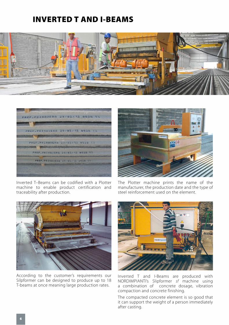
Inverted T–Beams can be codified with a Plotter machine to enable product certification and traceability after production.
The Plotter machine prints the name of the manufacturer, the production date and the type of steel reinforcement used on the element.
According to the customer’s requirements our Silpformer can be designed to produce up to 18 T-beams at once meaning large production rates.
Inverted T and I-Beams are produced with NORDIMPIANTI’s Slipformer sf machine using a combination of concrete dosage, vibration compaction and concrete finishing.
The compacted concrete element is so good that it can support the weight of a person immediately after casting.

Technology for the Precast and Prestressed Concrete Industry
7
T-Beams with special attributes NOW AVAILABLEfrom NORDIMPIANTI’s wf Wet Casting Machines
This machine uses a wetter concrete than that used by the other casting machines, either Extruder or Slipformer.
The wet casting machine can produce elements leaving the steel wires exposed at the cutting area of the element.
This is achieved after the elements have been moulded by the concrete being dragged forward by a guillotine device mounted on the finishing mould.
It can also produce elements having a corrugated top surface using a special stamping device mounted on the finishing mould.
The up/down control of the guillotine and the stamping device are completely automatic.
The length of the exposed steel wires can be precisely adjusted by means of a laser device which controls the position of the machine on the production bed.
Elements often require these attributes when being used in buildings constructed within seismic zones.
The insertion of steel mesh exposed on the top of the ribs is carried out by a different machine also supplied from NORDIMPIANTI.
Exposed wire Corrugated upper surface Steel mesh exposed* (Installed by a different machine also supplied from NORDIMPIANTI)
*THE EXPOSED STEEL MESH IS INSERTED BY A DIFFERENT MACHINE ALSO SUPPLIED FROM NORDIMPIANTI.
Finishing mould with optional hydraulically
operated guillotine

InvertedT and I BeamsApplications
NORDIMPIANTI SYSTEM SRL Via Erasmo Piaggio, 19/A 66100 Chieti (CH) - Italy
Tel. +39 0871 540222 Fax +39 0871 562408
[email protected] www.nordimpianti.com
THE PRODUCTS IN THE PICTURES MAY HAVE SOME ACCESSORIES NOT INCLUDED WITH THE BASIC MACHINE. THE DATA GIVEN IS STRICTLY INFORMATIVE. NORDIMPIANTI RESERVES THE RIGHT TO MODIFY THIS DATA WITHOUT PRIOR NOTICE.
adv
| eve
ntr
a.it3.2 | ENGLISH VERSION