Embed Size (px)
Citation preview
Nordic Boat Standard
1
Nordic BoatStandard
Commercial Boats lessthan 15 metres
1990
Denmark – Finland – Iceland
Norway – Sweden – Secretary
Nordic Boat Standard
2
PREAMBLE
Nordic Boat Standard for Commercial Boats has been developed in co-operationbetween the Maritime Administrations in Denmark, Finland, Iceland, Norway,Sweden and Det norske Veritas, in the following called "the Authorities". TheAuthorities consider that this Standard contain safety /requirements which areequivalent to valid national provisions for commercial vessels which are subjectto survey in the Nordic countries.
In order to achieve a rational approval procedure for new commercial boatssubject to survey within the Nordic countries, the Standard is based on a Nordicreciprocal acceptance of boats with "Nordic Approval" and that such approvalthereby also can be the base for a final national approval and certification forcommercial vessels subject to survey in the individual countries.
In respect of areas not covered by the Standard the boats shall be surveyed inaccordance with provisions issued by the Maritime Administration in thecountry where the boat shall be registered.
A National Maritime Administration may, based on accidents and other safetyconsiderations, in exceptional cases, adopt additional requirements in areascovered by the Standard. When such additional requirements are applied in anindividual country the Administration concerned shall communicate to theAuthorities particulars thereof.
A presumption for a reciprocal acceptance of "Nordic Approvals" is that theAuthorities shall have reciprocal right to insight into the documentations,surveys and tests on which approvals are based. This right should, however,normally not mean that the Authorities will request full documentation orundertake detailed surveys and tests in respect of each individual boat in areascovered by the approval.
In case of boats with "Nordic Approval" subject to requirements issued by anAdministration the documentation in respect of areas not covered by theStandard shall be submitted to the Administration in accordance with thenational requirements of the country concerned. In respect of areas covered bythe Standard the following documentation shall be submitted
Copy of documents for "Nordic Approval" General Arrangement drawing.
Nordic Boat Standard
3
When the national provisions provide for Operation Certificates, such certificatesshall be issued by the Administration in the country concerned. OperationCertificates are required in the Nordic countries for the following boats:
Boat type Denmark Finland Iceland Norway Sweden
Passengerboat
Number ofpassenger >12
All Loa>6 m
All Number ofpassenger>12
Fishing boat Grosstonnage>5
Loa>8.5 m
Loa>6 m
Loa>10.67 m
Grosstonnage >20
Work boatand tug
Gross >5 m All Loa >6 m - Gross >20 m
Without request for issue of "Operation Certificates" the Standard is fully orpartly applied as Administration requirements for the following boat types
Iceland - All boats imported to Iceland
Norway - Fishing boats with Loa between 5.5 and 10.67 m
Translation from the original languages by Per Eriksson, former Maritime SafetyDirector of the National Maritime Administration of Sweden.

Nordic Boat Standard
4
INDEX
GENERALC1 Nordic approvalC2 Definitions and symbols
BUOYANCYC3 Freeboard and stabilityC4 Doors, hatchways and windowsC5 Freeing ports and hull penetrationsC6 Watertight subdivision and bilge pumping
RUDDER AND MACHINERYC7 Rudder and steering arrangementsC8 Engine installationsC9 Fuel installationsC10 Propeller shafts and propellersC11 Electrical installations
ACCOMODATION AND EQUIPMENTC12 AccommodationC13 Protection of personnelC14 Fire safetyC15 Lifting gearsC16 Mooring and anchoring equipmentC17 Bridge and navigational equipment
SIMPLIFIED STRENGTH REQUIREMENTSC18 Simplified strength requirements for GRP boatsC19 Simplified strength requirements for steel boatsC20 Simplifies strength requirements for aluminium boats
DIMENSIONSC21 LoadsC22 Dimensioning of GRP boatsC23 Dimensioning of steel boatsC24 Dimensioning of aluminium boatsC25 Dimensioning of wooden boats
CONSTRUCTIONC26 Building of GRP boatsC27 Building of steel boatsC28 Building of aluminium boatsC29 Building of wooden boats
SUPPLEMENTARY PROVISIONSC30 Additional requirementsfor fishing boatsC31 Additional requirementsfor passenger boatsC32 Additional requirements for tugsC33 Ice strengthening
Nordic Boat Standard
5
NORDIC APPROVAL C1
Table of contents1 Nordic approval2 Content of the Standard3 Application for Nordic Approval4 Documentation5 Surveys and tests6 Approval documents and identification marking
1 NORDIC APPROVAL
1.1 For boats being built in accordance with the Standard an approval can beissued upon request when it after control as described in this Chapter isestablished that the requirements of the Standard are complied with.
1.2 The approval is called "NORDIC APPROVAL", which means that the Nordicco-operating authorities are satisfied that the requirements of the Standard arecomplied with.
1.3 NORDIC APPROVAL can be issued by the Maritime Administrations inDenmark, Finland, Iceland, Norway, Sweden and by Det norske Veritas.
1.4 The approvals do not include periodical controls after the boat has been put inservice.
1.5 Nordic approval procedures are not undertaken in respect of existing boats orboats where the control procedures described in paragraphs 3 and 5 of thischapter are not complied with during the building of the boat.
1.6 For boats which have been put in service and which are provided with aNordic Approval, the approval will cease to be valid when damages, modifi-cations or alterations have the effect that these Standards no longer arecomplied with.
Nordic Boat Standard
6
2 CONTENT OF THE STANDARD
2.1 The Nordic Boat Standard for Commercial Boats contains joint NordicStandards for commercial boats with a length less than 15 metres.
2.2 The Standard contains primarily direct requirements related to safety but alsorequirements related to quality, lifetime, fitness for user, etc when such itemsare of major importance for safety.
2.3 The same importance is, however, not attached to requirement related toquality, lifetime and fitness for the user when these items are not normally ofimportance for safety.
2.4 Boats built under other production conditions, using other materials, usingother methods, with other design or with other installations than those providedfor in the Standard may be approved on condition that the alternative arrange-ments are at least as effective as those required by the Standard.
2.5 Additional requirements may be applied when found necessary to achieve thatthe purpose of the Standard is complied with.
2.6 The Standard does not contain requirements in respect of:
- portable safety equipment;- portable navigational equipment;- communication equipment;- portable fire extinguishers;- electrical installations above 50 V;- special restrictions concerning operation which have to be decided
nationally;- tankers and other types of ship for carriage of dangerous goods.
2.7 For requirements which are mandatory the expression "shall" or "must not" areused. When the expressions "shall normally" or "shall normally not" are usedthe intention of the requirements of the Standard shall be complied with.
2.8 The Standard is based on the following conditions for use of boats:
- that the boat is not loaded with a weight greater than that for which it isapproved;
- that the boat is handled in a seamanlike manner in particular with regard toweather and sea conditions;
- that the use of propulsion power is adapted to the conditions;- that open boats are used in waters where it is possible to search an
emergency port before the weather becomes too bad;- that operational restrictions are applied so as to avoid ice accretion;- that operation in ice waters only takes place when the requirements of C33
are complied with, and in that case only in waters with thin ice, or with
Nordic Boat Standard
7
moderate concentration of drifting ice.
3 APPLICATION FOR NORDIC APPROVAL
3.1 Application for Nordic Approval shall be made by the manufacturer of the boator by his agent. It shall be in writing.
3.2 The one who applies for Nordic Approval undertakes to make possible thecontrol and to submit the information required by the Standard.
4 DOCUMENTATION
4.1 The documentation which shall be available before approval shall be such thatit constitutes basis for a total control of that all requirements of the Standardsrelated to construction, scantlings, arrangement, stability and loading, etc arecomplied with. The documentation shall be made available as a collectivedocumentation.
4.2 With the exemptions referred to in paragraph 4.3, the manufacturer shall for eachboat submit the following drawings and specifications in three copies:
(a) general arrangement drawing;(b) information on the building workshop;(c) information on which building and dimension requirements are used (cf.
C18 - C20 or C21 - C29);(d) drawing of the hull arrangement indicating material used, scantlings and
stiffening system;(e) lines drawing and body plan;(f) hydrostatic data for stability;(g) loading conditions with calculations for loading capacity, trim and
maximum draught;(h) specification or drawings of machinery and tank installation, bilge
pumping arrangement, rudder and steering gear, drainage of decks or soles(floorings), closing arrangements for external doors, hatchways, windows,emergency escapes, wheelhouse arrangement, ventilation and electricalinstallations;
(i) documentation for lifting gears referred to in C15.
4.3 For boats which are built in series with identical main dimension, constructionand hull form it will normally be sufficient that documentation and informationin respect of paragraphs (b), (c), (d), (e) and (f) are submitted only for the firstboat in the series.
Nordic Boat Standard
8
5 SURVEYS AND TESTING
5.1 For boats which are built and given scantlings in accordance with C18 to C20 itshall be arranged for a so rational survey that it normally will be sufficient with afinal survey which is mandatory for each boat. Where because of insulation andlack of accessibility, etc it is not possible to carry out a complete examinationduring the final survey the producer shall apply for additional examinationduring the building period.
5.2 For boats which are given scantlings in accordance with C21 to C25 or whichare built of other material or combination of materials other than those referredto in the Standard, it will–in addition to the final survey–normally be requireda more extensive examination, material testing, control of the workmanship andother proceedings during the building which will ensure that the requirements ofthe Standards in C26 to C29 are complied with.
5.3 Generally the final survey and testing shall be so comprehensive that it together withthe documentation satisfies that the requirements and the intentions of the Standard,as appropriate, are complied with.
5.4 A trial trip shall be made when the following shall be controlled:
- steering properties to both sides at low speed and at normal speed;- going astern;- steering and course stability at low speed;- stopping properties;
5.5 The result of survey and tests in accordance with 5.3 and 5.4 shall be recorded in afinal report which shall be prepared for each individual boat.
6 APPROVAL DOCUMENTS AND IDENTIFICATION MARKING
6.1 The Authority which has given a "Nordic Approval" in accordance with theseStandards shall issue a document which certifies that for each individual boat.
6.2 Each individual boat shall be marked for identification by the manufacturer. Themarking shall be permanent and contain the name of the manufacturer or builder andthe production number or build number of the boat.
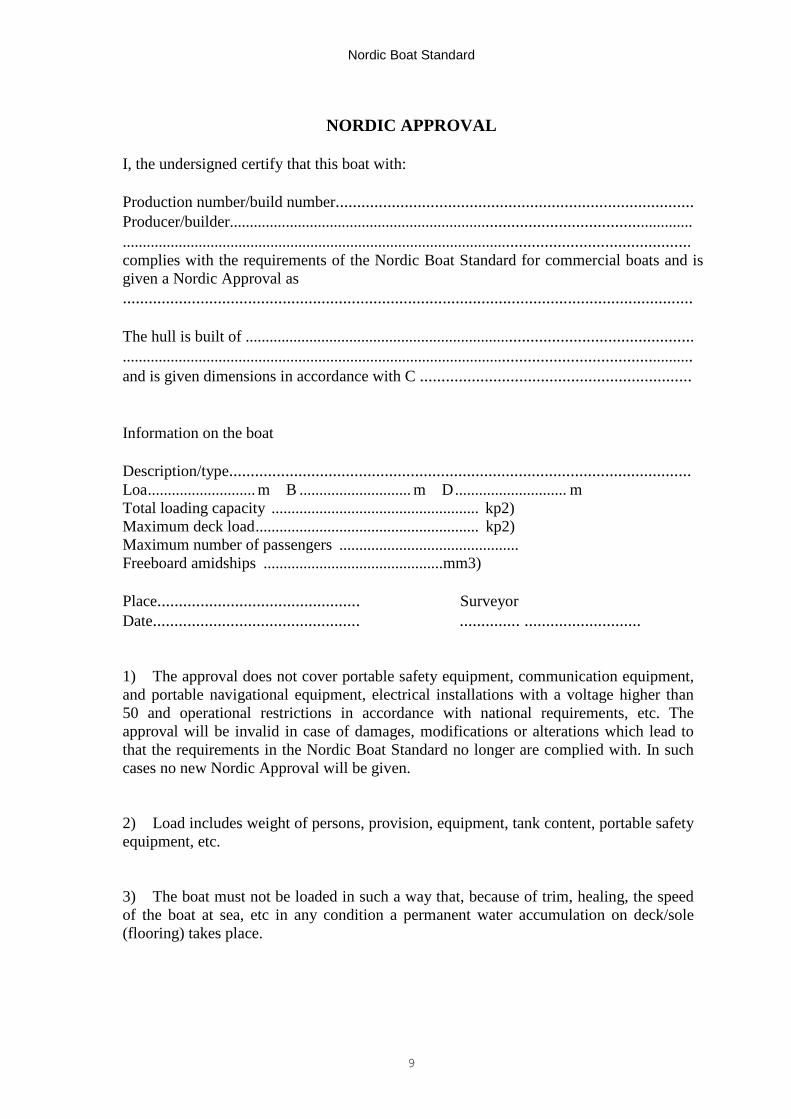
6.3 The form for the document referred to in 6.1 is given below.
Nordic Boat Standard
9
NORDIC APPROVAL
I, the undersigned certify that this boat with:
Production number/build number...................................................................................Producer/builder............................................................................................................................................................................................................................................................complies with the requirements of the Nordic Boat Standard for commercial boats and isgiven a Nordic Approval as....................................................................................................................................
The hull is built of .........................................................................................................................................................................................................................................................and is given dimensions in accordance with C ...............................................................
Information on the boat
Description/type...........................................................................................................Loa........................... m B ............................ m D............................ mTotal loading capacity .................................................... kp2)Maximum deck load........................................................ kp2)Maximum number of passengers .............................................Freeboard amidships .............................................mm3)
Place............................................... SurveyorDate................................................ .............. ...........................
1) The approval does not cover portable safety equipment, communication equipment,and portable navigational equipment, electrical installations with a voltage higher than50 and operational restrictions in accordance with national requirements, etc. Theapproval will be invalid in case of damages, modifications or alterations which lead tothat the requirements in the Nordic Boat Standard no longer are complied with. In suchcases no new Nordic Approval will be given.
2) Load includes weight of persons, provision, equipment, tank content, portable safetyequipment, etc.
3) The boat must not be loaded in such a way that, because of trim, healing, the speedof the boat at sea, etc in any condition a permanent water accumulation on deck/sole(flooring) takes place.
Nordic Boat Standard
10
DEFINITIONS AND SYMBOLS C2
Table of contents1 Definitions of boats2 Main dimensions3 Measuring of freeboard4 Loading capacity5 Lightweight and displacement6 Figures showing how to measure main dimensions and freeboard7 Symbols and units
1 DEFINITIONS OF BOATS
1.1 "Boat" is any craft which is used as a transport means by sea. For the purpose ofthe Standard the definition of a boat covers also craft which nationally are definedas a ship, vessel, etc.
1.2 "Boat types"
Fishing boat - Boat used for commercial fishing.
Passenger boat - Boat used for conveying passengers.
Tug - Boat used for towing, see also C32.
Work boat - Boat for other professional duties.
Commercial boat - Joint term for all commercial boats.
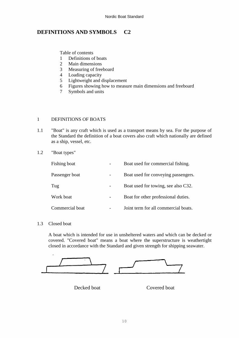
1.3 Closed boat
A boat which is intended for use in unsheltered waters and which can be decked orcovered. "Covered boat" means a boat where the superstructure is weathertightclosed in accordance with the Standard and given strength for shipping seawater.
Decked boat Covered boat
Nordic Boat Standard
11
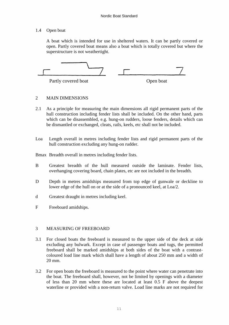
1.4 Open boat
A boat which is intended for use in sheltered waters. It can be partly covered oropen. Partly covered boat means also a boat which is totally covered but where thesuperstructure is not weathertight.
Partly covered boat Open boat
2 MAIN DIMENSIONS
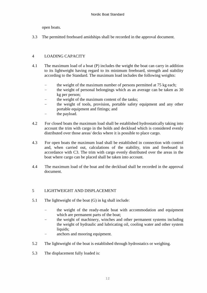
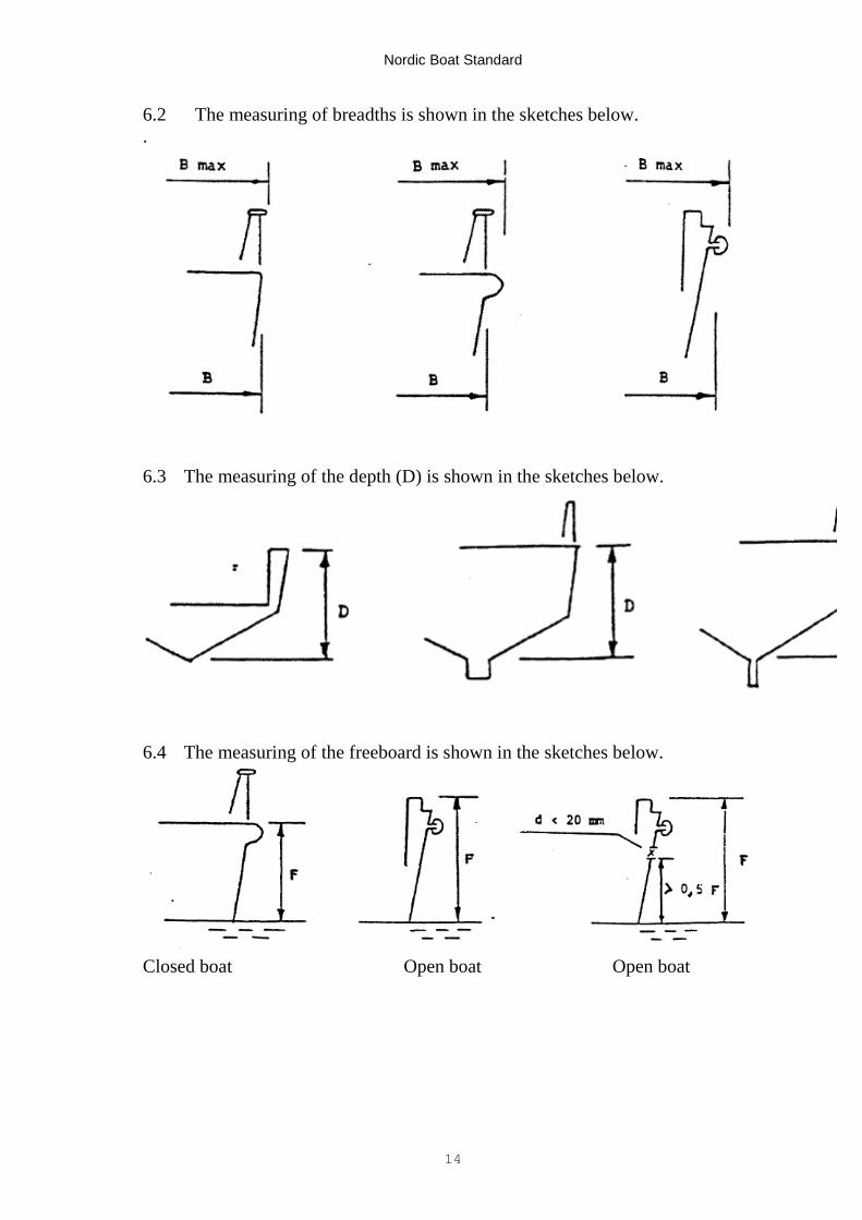
2.1 As a principle for measuring the main dimensions all rigid permanent parts of thehull construction including fender lists shall be included. On the other hand, partswhich can be disassembled, e.g. hung-on rudders, loose fenders, details which canbe dismantled or exchanged, cleats, rails, keels, etc shall not be included.
Loa Length overall in metres including fender lists and rigid permanent parts of thehull construction excluding any hung-on rudder.
Bmax Breadth overall in metres including fender lists.
B Greatest breadth of the hull measured outside the laminate. Fender lists,overhanging covering board, chain plates, etc are not included in the breadth.
D Depth in metres amidships measured from top edge of gunwale or deckline tolower edge of the hull on or at the side of a pronounced keel, at Loa/2.
d Greatest draught in metres including keel.
F Freeboard amidships.
3 MEASURING OF FREEBOARD
3.1 For closed boats the freeboard is measured to the upper side of the deck at sideexcluding any bulwark. Except in case of passenger boats and tugs, the permittedfreeboard shall be marked amidships at both sides of the boat with a contrast-coloured load line mark which shall have a length of about 250 mm and a width of20 mm.
3.2 For open boats the freeboard is measured to the point where water can penetrate intothe boat. The freeboard shall, however, not be limited by openings with a diameterof less than 20 mm where these are located at least 0.5 F above the deepestwaterline or provided with a non-return valve. Load line marks are not required for
Nordic Boat Standard
12
open boats.
3.3 The permitted freeboard amidships shall be recorded in the approval document.
4 LOADING CAPACITY
4.1 The maximum load of a boat (P) includes the weight the boat can carry in additionto its lightweight having regard to its minimum freeboard, strength and stabilityaccording to the Standard. The maximum load includes the following weights:
- the weight of the maximum number of persons permitted at 75 kg each;- the weight of personal belongings which as an average can be taken as 30
kg per person;- the weight of the maximum content of the tanks;- the weight of tools, provision, portable safety equipment and any other
portable equipment and fittings; and- the payload.
4.2 For closed boats the maximum load shall be established hydrostatically taking intoaccount the trim with cargo in the holds and deckload which is considered evenlydistributed over those areas/ decks where it is possible to place cargo.
4.3 For open boats the maximum load shall be established in connection with controland, when carried out, calculations of the stability, trim and freeboard inaccordance with C3. The trim with cargo evenly distributed over the areas in theboat where cargo can be placed shall be taken into account.
4.4 The maximum load of the boat and the deckload shall be recorded in the approvaldocument.
5 LIGHTWEIGHT AND DISPLACEMENT
5.1 The lightweight of the boat (G) in kg shall include:
- the weight of the ready-made boat with accommodation and equipmentwhich are permanent parts of the boat;
- the weight of machinery, winches and other permanent systems includingthe weight of hydraulic and lubricating oil, cooling water and other systemliquids;
- anchors and mooring equipment.
5.2 The lightweight of the boat is established through hydrostatics or weighing.
5.3 The displacement fully loaded is:
Nordic Boat Standard
13
Δ = P + G
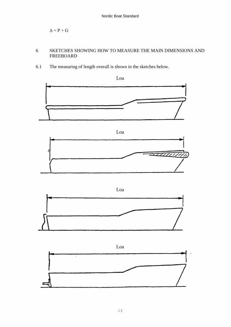
6 SKETCHES SHOWING HOW TO MEASURE THE MAIN DIMENSIONS ANDFREEBOARD
6.1 The measuring of length overall is shown in the sketches below.
Loa
Loa
Loa
Loa
Nordic Boat Standard
14
6.2 The measuring of breadths is shown in the sketches below..
6.3 The measuring of the depth (D) is shown in the sketches below.
6.4 The measuring of the freeboard is shown in the sketches below.
Closed boat Open boat Open boat
Nordic Boat Standard
15
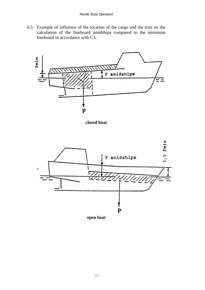
6.5 Example of influence of the location of the cargo and the trim on thecalculation of the freeboard amidships compared to the minimumfreeboard in accordance with C3.
closed boat
open boat

Nordic Boat Standard
16
7. SYMBOLS AND UNITS
7.1 Symbols
Symbol Unit Equivalence
A m2 areaA A amperea cm2 areaB m breadthb cm - " -C m3 / volumec c centiD m depthd m draughtd mm diameterE N/mm2 modulus of elasticityF m freeboardG kg lightweight displacementH m heighth m - " -I cm 4 moment of inertiaJ J, Nm jouleK N, kp forcek k correction factork k KiloL m lengthLoa m length overalll mm length of spanM Nm momentm m meterm m milliN N Newtonn number number, number of personso degrees degrees CelsiusP Kp, N force, weight, loadp N/mm2 pressurep kW motor effect (engine power)
Q m3/min capacityR cm radiusr revolution/sec revolutionS cm, mm moment arms mm frame/stiffener spacingt mm thicknessV knots speedv kg/m3 densityW, Z cm3 section modulusW W Watt
degree angle degree
N/mm2 mechanical stress
kg displacement
Nordic Boat Standard
17
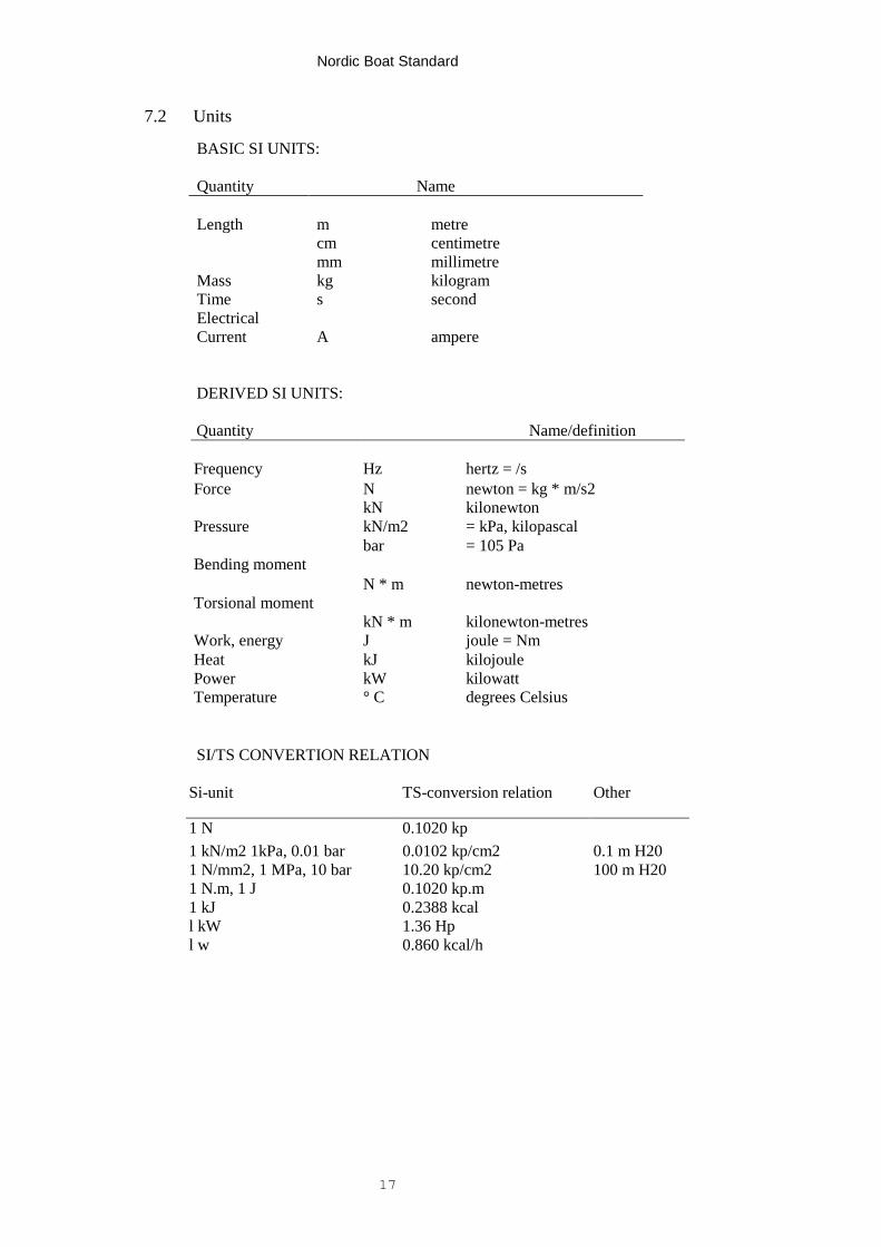
7.2 Units
DERIVED SI UNITS:
Quantity Name/definition
Frequency Hz hertz = /sForce N newton = kg * m/s2
kN kilonewtonPressure kN/m2 = kPa, kilopascal
bar = 105 PaBending moment
N * m newton-metresTorsional moment
kN * m kilonewton-metresWork, energy J joule = NmHeat kJ kilojoulePower kW kilowattTemperature ° C degrees Celsius
SI/TS CONVERTION RELATION
Si-unit TS-conversion relation Other
1 N 0.1020 kp1 kN/m2 1kPa, 0.01 bar 0.0102 kp/cm2 0.1 m H201 N/mm2, 1 MPa, 10 bar 10.20 kp/cm2 100 m H201 N.m, 1 J 0.1020 kp.m1 kJ 0.2388 kcall kW 1.36 Hpl w 0.860 kcal/h
BASIC SI UNITS:
Quantity Name
Length m metrecm centimetremm millimetre
Mass kg kilogramTime s secondElectricalCurrent A ampere
Nordic Boat Standard
18
FREEBOARD AND STABILITY C3
Table of contents1 Freeboard for closed boats2 Freeboard for open boats3 Stability for closed boats4 Stability for open boats5 Ballast
1 FREEBOARD FOR CLOSED BOATS
1.1 The freeboard amidships is decided having regard to stability, trim and hullstrength, etc, but shall not in any case and condition be less than 200 mmmeasured from the upper side of the deck at side to the waterline.
1.2 The forecastle deck or the freeboard deck forward shall in any load conditionhave a height above the waterline of at least 17 * Loa + 700 mm. The height offorecastle/freeboard deck forward may be reduced to the minimum freeboardgradually over a length of 0.3 Loa from the stem.
2 FREEBOARD FOR OPEN BOATS
2.1 The freeboard is decided having regard to stability, trim and hull strength, etc,but shall amidships not be less than the greater of:
(a) F = 3.2 * Δ (1000 * Loa * B) m(b) F = 0.5 m
2.2 Forward the freeboard shall not be less than 1.2 F. Aft the freeboard shall notbe less than 0.8 F.
3 STABILITY FOR CLOSED BOATS
3.1 Inclination tests shall be carried out with each individual boat. The tests shall becarried out with a ready-made boat with all permanent equipment installed.Particulars of the inclination tests shall be recorded in a report form andlightweight and location of centre of gravity shall be calculated.
3.2 When boats are built in series with identical main dimensions, construction,hull form, weight and location of permanent equipment, the requirement maybe dispensed with provided that it by calculation or weighing can be establishedthat the lightweight of the boat is the same as that calculated at the inclination
Nordic Boat Standard
19
test of a previous boat. An inclination test shall always be carried out with thetwo first boats in a series.
3.3 The righting arm (GZ) with free trim shall be calculated for the followingconditions:
(a) Lightweight condition with the minimum amount of fuel, water,equipment and persons on board. The total weights other than thelightweight (G) shall not be greater than 10 per cent of the maximumload of the boat (P);
(b) Loaded condition with maximum cargo in the hold, fuel tanks and othertanks totally full and maximum deck load. The total weight of cargo,equipment, persons, fuel and water must not be less than the totalloading capacity (P);
(c) Arrival condition with 10 per cent content in fuel and other tanks, emptyholds and maximum deck load;
(d) Other conditions which will give a less favourable result than (a), (b)and (c).
The centre of gravity in each of the conditions referred to in (a) to (d) shall becalculated as follows:
- For cargo holds including volumes in hatchway coamings, fuel tanksand other tanks the volumetric centre of gravity is calculated;
- For deckload except passengers and heavy items with a relatively highcentre of gravity, the centre of gravity is calculated with an evenlydistributed deckload with a density of 1.0 tons/m3, however, not lessthan 0.10 m above deck;
- Passengers are calculated as evenly distributed deckload with the centreof gravity 1.0 m above deck/flooring;
- For boats intended for the carriage of deckload in the form of heavyitems such as vehicles with a relatively high centre of gravity the mostrelevant centre of gravity shall be assumed having regard to type ofcargo in question.
3.4 Closed boats shall in all conditions have:
- a righting arm at 30 degrees heeling of at least GZ30 = 0.20 m;- the greatest value of the GZ curve shall be at an angle of heel greater than
25 degrees;- the GZ curve shall be positive up to heeling angle of 40 degrees; and- the GZ curve shall be terminated at the heeling angle where a filling
opening will come below water.
3.5 Openings which are not provided with weathertight closing arrangements shallbe considered as filling openings where water will flood the boat when such anopening is submerged.
Nordic Boat Standard
20
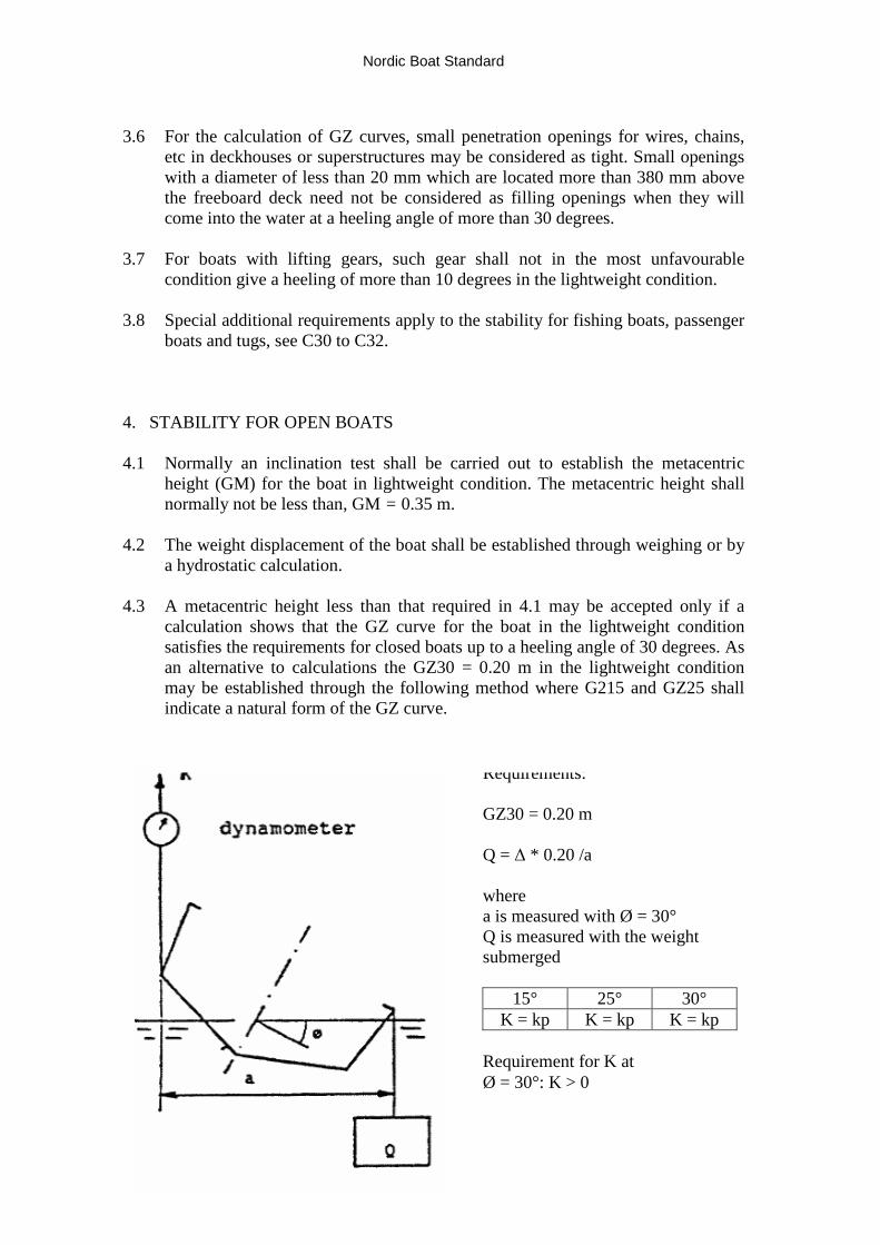
Requirements:
GZ30 = 0.20 m
Q =Δ* 0.20 /a
wherea is measured with Ø = 30°Q is measured with the weightsubmerged
15° 25° 30°K = kp K = kp K = kp
Requirement for K atØ = 30°: K > 0
3.6 For the calculation of GZ curves, small penetration openings for wires, chains,etc in deckhouses or superstructures may be considered as tight. Small openingswith a diameter of less than 20 mm which are located more than 380 mm abovethe freeboard deck need not be considered as filling openings when they willcome into the water at a heeling angle of more than 30 degrees.
3.7 For boats with lifting gears, such gear shall not in the most unfavourablecondition give a heeling of more than 10 degrees in the lightweight condition.
3.8 Special additional requirements apply to the stability for fishing boats, passengerboats and tugs, see C30 to C32.
4. STABILITY FOR OPEN BOATS
4.1 Normally an inclination test shall be carried out to establish the metacentricheight (GM) for the boat in lightweight condition. The metacentric height shallnormally not be less than, GM = 0.35 m.
4.2 The weight displacement of the boat shall be established through weighing or bya hydrostatic calculation.
4.3 A metacentric height less than that required in 4.1 may be accepted only if acalculation shows that the GZ curve for the boat in the lightweight conditionsatisfies the requirements for closed boats up to a heeling angle of 30 degrees. Asan alternative to calculations the GZ30 = 0.20 m in the lightweight conditionmay be established through the following method where G215 and GZ25 shallindicate a natural form of the GZ curve.
Nordic Boat Standard
21
In order to avoid lift of the boat during the measuring, the dynamometer and theweight shall be placed longitudinally so that the trim of the boat will not changeduring the test.
4.4 Where the height of the sole (flooring) and other areas for cargo is such that thecargo mainly will be located above the waterline in fully loaded condition, astability test with a load (weights) which is half the loading capacity of the boat(0.5 P) placed on one side of the centreline at 0.25 B at the cargo area shall becarried out. This must not result in:
- a heeling angle greater than 15 degrees;- a freeboard of less than 200 mm at the place where water first will flood
the boat.
Such a stability test is not required for passenger boats.
5 BALLAST
5.1 Ballast shall be secured in the boat in such a way that it will not move even if theboat is inclined to 90 degrees.
Nordic Boat Standard
22
DOORS, HATCHWAYS AND WINDOWS C4
Table of contents1 Weathertight hatchways on closed boats2 Doors on closed boats3 Hatchways and doors on open boats4 Windows5 Ports in the hull side
1 WEATHERTIGHT HATCHWAYS ON CLOSED BOATS
1.1 Coamings of hatchways on exposed freeboard decks shall have a height abovethe deck of at least 380 mm. Similar hatchways on first deck above freeboarddeck shall have a coaming height of at least 300 mm.
1.2 Coaming heights as for hatchways in paragraph 1.1 may never the less bereduced to 230 mm and 150 mm as the case may be, on condition that minimumfreeboards are increased accordingly.
1.3 Hatchways which may be opened at sea shall be hinged or attached with chainsand be capable of being secured when open.
1.4 Coamings of small hatchways (companionway hatchways, etc) which are notnormally opened when the boat is at sea may be minimum 230 mm on the free-board deck and 100 mm on the first deck above freeboard deck.
1.5 Heights of hatchway coamings may further be reduced or omitted for
- machinery space hatchways which are used only in connection withmaintenance and repair of machinery and other hatchways which similarlyare not necessary for the normal operation of the boat;
- small hatchways with an area of not more than 0.1 m2.
This applies on condition that the covers have gaskets and securing means withsmall spacing and which cannot be opened without special measures.
Nordic Boat Standard
23
1.6 In order to ensure that the hatchways are weathertight it is required that
- the hatchway covers are fitted so that they are not pressed out;- battening down devices are fitted at distances of not more than 600 mm.
2. DOORS ON CLOSED BOATS
2.1 Openings which from an exposed freeboard deck lead to a space below deck or asuperstructure which is part of the buoyancy of the boat for stability shall havedoors which cannot be opened inwards. The door shall be stiffened andconstructed in such a way that the whole construction is of equal strength as thebulkhead otherwise. Devices for weathertight closing of such doors shall begaskets and at least two securing devices in addition to the hinges.
2.2 Doors shall be capable of being opened and closed from both sides of thebulkhead.
2.3 The sill height of such doors on the freeboard deck shall be at least 380 mm.Similar doors on the first deck above freeboard deck shall have a sill height of atleast 300 mm.
2.4 The sill heights as for doors in paragraph 2.3 may nevertheless be reduced to 230mm and 150 mm as the case may be, on condition that minimum freeboards areincreased accordingly.
3. HATCHWAYS AND DOORS ON OPEN BOATS
3.1 Hatchways to machinery spaces and hatchways and doors to coveredaccommodation spaces shall be provided with closing devices.
4 WINDOWS
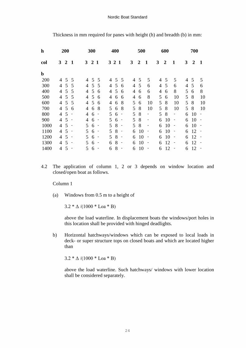
4.1 Windows shall be given pane thickness as indicated in the following table whichapplies to panes of tempered glass, carbonate glass, acrylic glass and laminatedglass.
Nordic Boat Standard
24
Thickness in mm required for panes with height (h) and breadth (b) in mm:
h 200 300 400 500 600 700
col 3 2 1 3 2 1 3 2 1 3 2 1 3 2 1 3 2 1
b200 4 5 5 4 5 5 4 5 5 4 5 5 4 5 5 4 5 5300 4 5 5 4 5 5 4 5 6 4 5 6 4 5 6 4 5 6400 4 5 5 4 5 6 4 5 6 4 6 6 4 6 8 5 6 8500 4 5 5 4 5 6 4 6 6 4 6 8 5 6 10 5 8 10600 4 5 5 4 5 6 4 6 8 5 6 10 5 8 10 5 8 10700 4 5 6 4 6 8 5 6 8 5 8 10 5 8 10 5 8 10800 4 5 - 4 6 - 5 6 - 5 8 - 5 8 - 6 10 -
900 4 5 - 4 6 - 5 6 - 5 8 - 6 10 - 6 10 -
1000 4 5 - 5 6 - 5 8 - 5 8 - 6 10 - 6 10 -
1100 4 5 - 5 6 - 5 8 - 6 10 - 6 10 - 6 12 -
1200 4 5 - 5 6 - 5 8 - 6 10 - 6 10 - 6 12 -
1300 4 5 - 5 6 - 6 8 - 6 10 - 6 12 - 6 12 -
1400 4 5 - 5 6 - 6 8 - 6 10 - 6 12 - 6 12 -
4.2 The application of column 1, 2 or 3 depends on window location andclosed/open boat as follows.
Column 1
(a) Windows from 0.5 m to a height of
3.2 *Δ /(1000 * Loa * B)
above the load waterline. In displacement boats the windows/port holes inthis location shall be provided with hinged deadlights.
b) Horizontal hatchways/windows which can be exposed to local loads indeck- or super structure tops on closed boats and which are located higherthan
3.2 * Δ /(1000 * Loa * B)
above the load waterline. Such hatchways/ windows with lower locationshall be considered separately.
Nordic Boat Standard
25
Column 2
(a) Windows in a superstructure, wheelhouse, etc on closed boats wherethe window location is higher than
3.2 * Δ /(1000 * Loa * B)
Column 3
(a) Windows in superstructures on open boats (partly covered boats)where the window location above the load waterline is higher thanF for the boat.
(b) Windows in the second superstructure on closed boats, except inthe front bulkhead of the wheelhouse, in which case column 2 shallbe applied.
4.3 Windows in the hull side shall never be placed lower than 500 mm abovethe load waterline and shall be placed at least 10 mm inside the hull side.A window frame which is arranged outside the glass must not projectmore than 5 mm outside the hull side.
4.4 Coloured glass or window of a material which is susceptible toscratching must not be used in the front of and at the sides of theoperator's place.
4.5 Windows shall be satisfactorily fastened taking into account particularlythe risk for being pressed in. When the risk for that the glass is pressedout of the frame because of the size of the window, the bendingproperties of the glass, the location of the window near the waterline, etc,special measures shall be taken to prevent the pressing in of the glass byincreasing the contact surface between glass and frame or by fixing theglass to the frame.
4.6 Windows in spaces which shall be included in the buoyancy for stabilityshall be fastened in a fixed frame which is mechanically attached.
4.7 Where rubber profiles are used the glass shall be mounted in a way thatis safe in respect of pressing in and the thickness of the glass in column 1and 2 shall be increased with 20 percent. If glass other than temperedglass is used the thickness shall be adapted to the stiffness and strength ofthe material.
4.8 If windows with greater length or breadth than those in the table areused, equivalent strength and stiffness shall be demonstrated.

Nordic Boat Standard
26
5 PORTS IN THE HULL
5.1 Ports in the hull constituting the freeboard on open boats shall be so constructed thatthey are watertight. Ports and coamings shall have at least the same strength as thehull otherwise. Ports at sides, stem and stern on closed boats must not be fittedbelow the freeboard deck.
5.2 The lowest point of a port opening on open boats must not be lower than 200 mmabove the load waterline.
5.3 For ports with the lowest point of the opening lower than 500 mm above the loadwaterline solid gaskets and battening down devices with a distance of not more than300 mm are required. Ports located higher than 500 mm above the load water lineshall be so arranged that significant amounts of water will not penetrate into theboat and shall be fitted with satisfactory closing arrangement.
5.4 Ports which can be folded down shall be fitted with stopping arrangements in thelowest position.
Nordic Boat Standard
27
FREEING PORTS AND HULL PENETRATIONS C5
Table of contents1 Drainage of decks on closed boats2 Hull penetrations3 Ventilation openings4 Air pipes
1 DRAINAGE OF DECKS ON CLOSED BOATS
1.1 Freeing ports shall be distributed along the deck in such a way that the locations areconcentrated to the areas where the collection of water on deck will be the greatesthaving regard to sheer, probable trim, etc.
1.2 On boats where the bulwark, end bulkheads of closed superstructures, deckhouses,etc constitute wells, the minimum effective freeing port area at each side of the boatshall be:
A = 0.02 * V m2
where V is the volume of well in cubic metres.
1.3 The volume of the well is calculated as deck area times bulwark height minusvolume of hatchways, deckhouses, etc up to the bulwark height.
1.4 Flaps or external rubber claps in freeing ports, if fitted, shall be fastened withhinges at the upper edge. Such devices shall have sufficient clearance to preventjamming. The hinges shall be made of non-corroding material. Arrangements forlocking of freeing port flaps are not permitted.
1.5 Large freeing ports shall be fitted with bars, spaced with a maximum distance of330 mm apart, the distance below the lowest bar shall, however, not be greater than230 mm.
Nordic Boat Standard
28
2 HULL PENETRATIONS
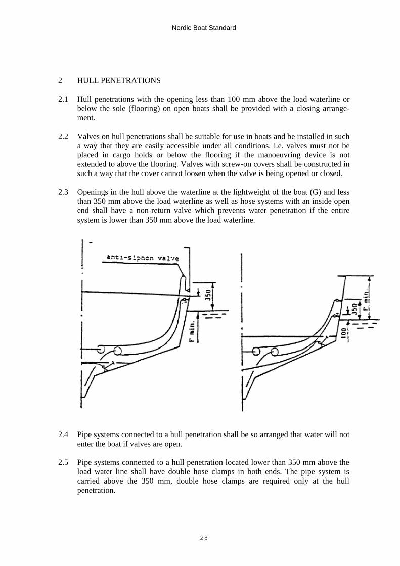
2.1 Hull penetrations with the opening less than 100 mm above the load waterline orbelow the sole (flooring) on open boats shall be provided with a closing arrange-ment.
2.2 Valves on hull penetrations shall be suitable for use in boats and be installed in sucha way that they are easily accessible under all conditions, i.e. valves must not beplaced in cargo holds or below the flooring if the manoeuvring device is notextended to above the flooring. Valves with screw-on covers shall be constructed insuch a way that the cover cannot loosen when the valve is being opened or closed.
2.3 Openings in the hull above the waterline at the lightweight of the boat (G) and lessthan 350 mm above the load waterline as well as hose systems with an inside openend shall have a non-return valve which prevents water penetration if the entiresystem is lower than 350 mm above the load waterline.
2.4 Pipe systems connected to a hull penetration shall be so arranged that water will notenter the boat if valves are open.
2.5 Pipe systems connected to a hull penetration located lower than 350 mm above theload water line shall have double hose clamps in both ends. The pipe system iscarried above the 350 mm, double hose clamps are required only at the hullpenetration.
Nordic Boat Standard
29
3 VENTILATION OPENINGS
3.1 On closed boats the ventilation openings shall have a height of at least 450 mmabove deck and shall be/such that they because of their arrangement and locationwill not cause water filling of the boat in breaking seas. Height and location ofvents shall be such that the ventilation openings will not come below water at aheeling of up to 30 degrees on open boats and 4 0 degrees on closed boats.
4 AIR PIPES
4.1 Air pipes shall have a height to the upper edge of the bulwark, however, at least 450mm above the deck and shall be so located that they are protected against damagesin connection with work on deck.
4.2 The air pipes shall be so arranged, e.g. with a non-return valve or a goose-neck, thata sea shipped will not penetrate into a tank, battery room, etc.
4.3 The air pipes to fuel tanks shall terminate outside the boat on open boats and abovedeck on covered boats.
Nordic Boat Standard
30
WATERTIGHT SUBDIVISION AND BILGE PUMPING C6
Table of contents1 Watertight subdivision2 Collection of oil spills3 Main bilge system4 Emergency bilge system5 Water level alarm6 Bilge pipes and hoses
1 WATERTIGHT SUBDIVISION
1.1 Engine compartments, cargo holds and accommodation spaces in closed boatsshall from bottom to deck be subdivided by watertight bulkheads. In open boatsthe machinery space shall have a watertight bulkhead up to the waterline inloaded condition.
1.2 Hatchways and door openings in watertight bulk heads shall be provided withclosing arrangements and have the same strength as the bulkhead where they arearranged.
1.3 Where pipes and electrical wires are carried through a watertight subdivisionbulkhead, the penetration arrangements shall be made to ensure the watertightintegrity of the bulkheads.
2 COLLECTION OF OIL SPILLS
2.1 The bottom space in the engine compartment shall preferably be capable ofbeing drained with the aid of a fixed bilge pumping system to a bilge watertank. The system must not have connection to the bilge system otherwise or aconnection for discharge into the sea.
Nordic Boat Standard
31
2.2 The bilge water tank shall be a permanently installed tank. Alternativelyseveral portable tanks with a capacity of not more than 25 litres each maybe used. Such tanks shall be suitable for taking ashore.
2.3 A permanently installed bilge water tank shall have air pipes to the opendeck. The content of the tank shall be capable of being discharged to areception facility ashore via a connection on deck.
3. MAIN BILGE SYSTEM
3.1 The main bilge system shall be capable of pumping from and draining ofall watertight compartments. Watertight compartments of limited size maybe drained to an adjacent space. The drainage hole shall in such cases betightened with a firmly fitted plug.
3.2 A fixed motor driven or electrically driven bilge pump shall be installedwhich via a fixed piping system with a non-return-valve mounted to eachsuction pipeline is capable of draining all watertight compartments.Alternatively each compartment can be drained with a separate pump. Eachpump shall be capable of being operated from the steering place.
3.3 Each pump shall have at least the following capacity:
Loa Litres per minute
5.50 - 8.00 608.00 - 9.99 8010.00 - 11.99 12012.00 - 180
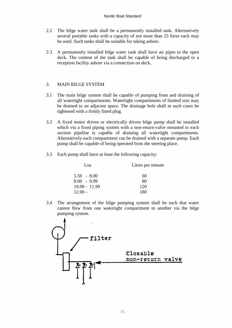
3.4 The arrangement of the bilge pumping system shall be such that watercannot flow from one watertight compartment to another via the bilgepumping system.
Nordic Boat Standard
32
3.5 If the bilge pumping system is arranged with electrically driven pumps, the pumpsmust not be connected to the starting accumulator of the motor. If the bilge pump islocated in the cargo hold, it shall be easily accessible for cleaning under allconditions or alternatively a stand-by pump shall be available in the cargo hold.
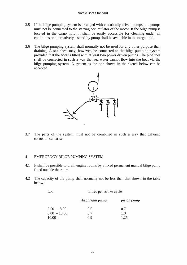
3.6 The bilge pumping system shall normally not be used for any other purpose thandraining. A sea chest may, however, be connected to the bilge pumping systemprovided that the boat is fitted with at least two power driven pumps. The pipelinesshall be connected in such a way that sea water cannot flow into the boat via thebilge pumping system. A system as the one shown in the sketch below can beaccepted.
3.7 The parts of the system must not be combined in such a way that galvaniccorrosion can arise.
4 EMERGENCY BILGE PUMPING SYSTEM
4.1 It shall be possible to drain engine rooms by a fixed permanent manual bilge pumpfitted outside the room.
4.2 The capacity of the pump shall normally not be less than that shown in the tablebelow.
Loa Litres per stroke cycle
diaphragm pump piston pump
5.50 –8.00 0.5 0.78.00 –10.00 0.7 1.010.00 - 0.9 1.25
Nordic Boat Standard
33
4.3 If the boat has two engines installed, or an auxiliary engine is installed, the manualpump may be substituted by a pump direct or indirectly driven by the auxiliaryengine or driven by the other than the main engine mentioned in 3.2.
5 WATER LEVEL ALARM
5.1 Closed boats shall be fitted with an alarm for a high water level in the motor room.
6 DRAINAGE PIPES AND HOSES
6.1 The bilge water pumping system in the motor room shall be of non-combustiblematerial or flexible hoses which shall be approved in accordance with sectionMC11.
6.2 Bilge piping systems are to be properly installed in the entire length.
Nordic Boat Standard
34
RUDDER AND STEERING ARRANGEMENTS C7
Table of contents1 Installation2 Forces acting on the steering gear3 Rudder shafts4 Rudders
1 INSTALLATION
1.1 The steering gear shall ensure a steady and safe manoeuvring of the boat at themaximum engine power for which the boat is certified. The steering devices andwheel, if fitted, shall comply with chapters MC12 and MC14. The steeringdevices shall be protected so that they do not come in contact with cargo or thelike which can block or make difficult the steering.
1.2 Rudder stops are required in case of remote control of the steering.
1.3 Boats approved for outboard motors with a higher power than 15 kW shall befitted with a permanent wheel steering.
1.4 A steering console or similar arrangement in the steering system shall be built,stiffened and secured in such a way that it can absorb the forces to which it will beexposed taking into account also the forces the operator of the boat will transfer tothe wheel at heeling and other movements of the boat. At specially exposed placesbe bolt connections shall be made of stainless steel. All bolt connections whichare part of the steering system installation in the boat shall be locked.
1.5 All penetrations in a motor well such as holes for a steering cable shall beeffectively sealed by means of a sleeve or similar device.
1.6 Hydraulic hoses and pipes shall be protected from contact with hot parts and frommechanical wear and be clamped at intervals of 300 mm. The oil fill opening andair bleeders shall be easily accessible.
1.7 Emergency steering shall be possible on all rudderstocks in case of remotelycontrolled steering. Emergency steering below deck may be accepted providedthat communication to the open deck is arranged.
Emergency steering is not required in boats with two propellers provided that itfrom the results of the manoeuvring tests is evident that the boat can be steeredsafely with the propellers.
Emergency steering is not required in boats where two independent steering syst-ems are installed and where a hydraulic system does not contain flexible hoses.

Nordic Boat Standard
35
2. FORCES ACTING UPON STEERING SYSTEMS
2.1 Unless otherwise stated, the following symbols shall be used:
K steering force in Newton;P rudder force in N ; P = 110 * A * V2
A rudder area in m2
V the maximum speed of the boat in knotsSa length in mm of the steering armSb distance in mm from the centre of pressure (Tc) to the nearest rudder
shaft bearing above the rudderSv perpendicular distance in mm from the centre of pressure to the centre of
rotation of the rudder. Plate rudders have the centre of pressure at a pointsituated 40 per cent aft of the leading edge of the rudder
U maximum motor power in kWM moment in N mmdv diameter in mm of massive rudderstockσ 2 yield stress in N/mm2.
2.2 The steering force in boats with outboard motors or I/O drives is:
K = 10 * U N
2.3 The steering force in boats with rudder is:
K = P * Sv/Sa N
3 RUDDER STOCKS
3.1 If the rudder has a lower bearing point (heel pintle) with at least the same stiffnesssidewise as the rudderstock, the moment is calculated as follows:
M = 1.15 (0.25 * P * Sb + 0.5 * P √(Sb + 2* Sv2))
Nordic Boat Standard
36
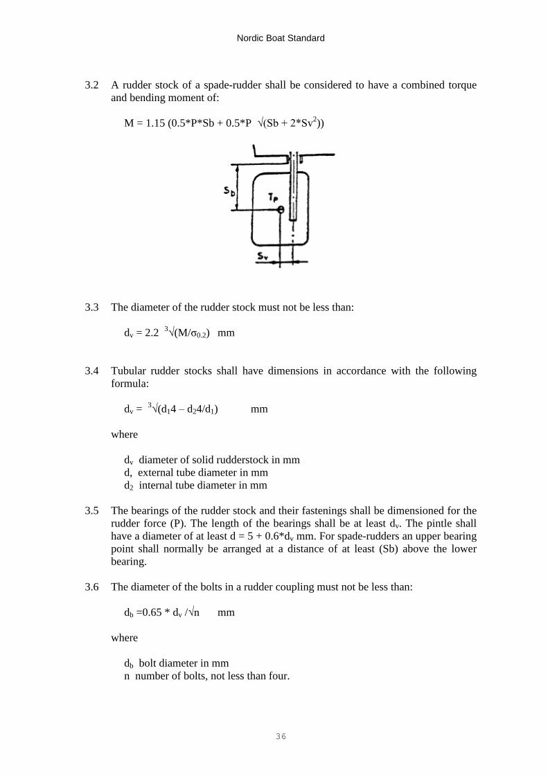
3.2 A rudder stock of a spade-rudder shall be considered to have a combined torqueand bending moment of:
M = 1.15 (0.5*P*Sb + 0.5*P √(Sb + 2*Sv2))
3.3 The diameter of the rudder stock must not be less than:
dv = 2.2 3√(M/σ0.2) mm
3.4 Tubular rudder stocks shall have dimensions in accordance with the followingformula:
dv = 3√(d14–d24/d1) mm
where
dv diameter of solid rudderstock in mmd, external tube diameter in mmd2 internal tube diameter in mm
3.5 The bearings of the rudder stock and their fastenings shall be dimensioned for therudder force (P). The length of the bearings shall be at least dv. The pintle shallhave a diameter of at least d = 5 + 0.6*dv mm. For spade-rudders an upper bearingpoint shall normally be arranged at a distance of at least (Sb) above the lowerbearing.
3.6 The diameter of the bolts in a rudder coupling must not be less than:
db =0.65 * dv /√n mm
where
db bolt diameter in mmn number of bolts, not less than four.
Nordic Boat Standard
37
The pitch circle radius for the coupling bolts must not be less than the diameter ofthe rudder stock. The thickness of the coupling flange and the width of the flangeoutside the bolt holes must not be less than db.
3.7 The top packing box of the rudder stock housing shall have a height of at least 350mm above the load waterline and be provided with a sealing. Where this is notpractically possible, a grease filled packing box shall be arranged.
4. RUDDERS
4.1 Rudders of steel, aluminium, and glass fibre reinforced polyester shall have an allthrough rudder stock from the rudder coupling down to the pintle. The diameter ofthe rudder stock must not be less than the diameter of the pintle in accordancewith 3.5. In case of spade-rudders the diameter may, however, be reduced linearlydown from the rudder-coupling.
4.2 Rudders of steel and aluminium constructed as plate rudders or profile ruddersshall have at least two reinforcements across the rudder stock with a distance ofmaximum 600 mm. The thickness of the reinforcements must not be less than thethickness of the plate in the profile rudder according to 4.4.
4.3 Plate-rudders shall have a thickness of at least:
t = 3 + 0.125 * dv mm
4.4 The plating in a profile rudder shall have a thickness of at least:
td = k * te sun
where
k = 0.46 for steel or aluminiumk 0.33 for stainless steelte thickness of plate-rudder according to 4.3.
4.5 Rudders made of glass fibre reinforced polyester shall be profile rudders and havesteel reinforcements welded to the rudder stock with maximum distance of 200mm. The thickness of the steel reinforcements shall at least the same as thethickness of a plate rudder according to 4.3, the breadth at least ten times thethickness and the length not less than 75 per cent of the distance from the rudderstock to the trailing edge or leading edge of the rudder.
4.6 A rudder made of glass fibre reinforced polyester which is laminated in two partsshall be filled with reinforced polyester or equivalent material and the parts shall beeffectively glued together on flanges and at the edges. The thickness of the side
Nordic Boat Standard
38
parts shall not be less than the thickness of the plate in a profile rudder of steel oraluminium according to 4.4.
4.7 Wooden rudders shall be made of oak and be attached to the rudder stock and thepintle with steel forks with a thickness of a plate-rudder according to 4.3. The steelforks shall be welded with continuous welds to the rudder stock and the pintle andbolted to the rudder with at least three upper bolts and two lower bolts which shallhave the same diameter as bolts in a rudder coupling according to 3.6.
4.8 Rudders of oak shall have a thickness of at least:
tt = 7.3 * te mm
where te is the thickness of a plate-rudder according to 4.3.
Nordic Boat Standard
39
ENGINE INSTALLATIONS C 8
Table of contents1 Engines2 Engine spaces3 Installation4 Exhaust systems5 Engine control6 Installation of outboard motors7 Sea water cooling systems8 Ventilation of motor and tank spaces
1 ENGINES
1.1 Commercial boats shall be provided with diesel engines. Commercial boats other thanpassenger boats may, however, have gasoline outboard motors provided that Loa * Bis less than 20.
1.2 Inboard propulsion engine with power greater than 100 kW shall be type approved formarine use. Individual survey certificates are not required.
1.3 Where elastic mounting of a propulsion engine is used, the propeller shaft shall belonger than 40 times the diameter of the shaft when an elastic shaft coupling is notarranged.
2 ENGINE SPACES
2.1 The engine space shall be arranged so that it cannot be used for other purposes. Thenormal service points of the engine shall be easily accessible. Stowage spaces shall beseparated from the engine space by bulkheads or similar arrangements. In order tosimplify big service work on the engine the divisions may be detachable if acceptablehaving regard to the division requirements.
2.2 Windows or other types of lighting glass must not be fitted in the boat side, enginecasing or the deck above the engine space. The room shall be equipped with electricallight.
Nordic Boat Standard
40
3 INSTALLATION
3.1 Flexible hoses shall be accessible and visible for inspection. They shall comply withchapters MC9, MC10 and MC11 and be fitted with double acid resistant hose clamps.
4 EXHAUST SYSTEMS
4.1 Material in the seawater cooling system shall be corrosion resistant. The parts of thesystem must not be combined in such a way that galvanic corrosion will arise.
4.2 In the case of a multiple engine installation each motor shall have its separate exhaustsystem.
4.3 Exhaust pipes shall be mounted so that mechanical wear is avoided. Moulding in of anexhaust line is, however, not permitted. Drainage is not permitted at a part of the linewhich passes through enclosed accommodation spaces.
4.4 Exhaust outlets shall be at least 100 mm above the load waterline or connected to afixed pipeline which is drawn up to at least 100 mm above the load waterline. Anexhaust line shall always be drawn so that a part of it is at least 350 mm above theload waterline with a slope downwards to the outlet.
5 ENGINE CONTROL
The propulsion engine shall be capable of easy manoeuvring from the steering placeand the control devices for inboard engines shall be arranged so that the followinginformation is available at the steering place:
- the revolution of the propulsion machinery;- lubrication oil pressure of the propulsion engine;- lubrication oil pressure of the gear and hydraulic pressure, if applicable;- cooling water temperature;- cooling water failure in the exhaust system.
The control instruments shall be marked with abnormal operational conditions andfitted with adjustable lighting. The functions listed above except the revolution of thepropulsion machinery shall be fitted with alarms.
Nordic Boat Standard
41
6 INSTALLATION OF OUTBOARD MOTORS
6.1 The transom shall be fitted with a well attached plate as a protection for the fasteningbolts for the engine. The upper part of the plate shall have a marked ridge of at least 5mm. A suitable protection plate shall be mounted at the outer side of the transom.
6.2 Outboard motors with a power greater than 15 kW shall be fastened to the stern usingthrough bolts with nuts.
6.3 Boats with motors having a power greater than 15 kW shall have a motor well drainedto the sea through at least one hole with a diameter of at least 15 mm.
6.4 Holes for the control cable and fuel pipe in the engine well shall be tightened withsleeves or the like.
6.5 The well shall have such a size that the motor can be easily manoeuvred and tilted.
7 SEAWATER COOLING SYSTEM
7.1 Materials in a seawater cooling system shall be corrosion resistant. The parts of thesystem must not be combined in such a way that galvanic corrosion arises.
7.2 Seawater intake shall be provided either with a strainer or a filter.
7.3 External cooling water line shall be protected at the forward end.
7.4 If a filter is part of a seawater cooling system for the cooling of the engine, the filtershall be mounted so that it can be cleaned without tools and when the engine isrunning.
7.5 Pipes and filters in the engine space must not be made of thermoplastics. Small hosesections may be accepted.
8 VENTILATION OF ENGINE AND TANK SPACES
8.1 The air intake for the engine space shall be arranged so that the air needed for theengine in accordance with the engine manufacturer's guide lines, but at least 7 cm/kW,is satisfied. The air intake for the engine space shall be placed in the opposite side tothe air intake for the engine.
8.2 The ventilation openings shall be provided with closing devices which are operatedfrom a place outside the engine space and which can be secured in both open andclosed position.
8.3 Fuel filling opening and tank vent fitting shall be arranged and mounted so that anyspill at over filling or gas from the vent fitting will not penetrate into the boat.
Nordic Boat Standard
42
FUEL INSTALLATIONS C9
Table of contents1 General2 Fuel tanks3 Fuel lines
1. GENERAL
1.1 Fuel lines to the engine shall be fixed mounted and shall be fitted with a filter and awater separating system which both shall be capable of being drained and cleanedwithout use of tools.
Filters must not be located in fuel tanks.
1.2 The return fuel line shall end near the bottom of the tank.
1.3 Fuel tank shall be mounted on and be attached to a strong bed. A fuel tank shall not belocated adjacent to other parts in such a way that the air circulation is obstructed.
2 FUEL TANKS
2.1 For diesel oil tanks a fuel line with a shut-off valve in the bottom of the tank isaccepted.
Drainage valve with tightening plug (tätnings plugg) is also accepted in the tankbottom. Connection piping between diesel oil tanks may be accepted. A shut-off valveshall than be fitted at each tank connection.
2.2 Boats with outboard motor shall have an appropriate fastening arrangement for aportable gasoline tank when a permanently mounted tank is not arranged. Thearrangement shall be such that the tank can easily be put into place.
2.3 A fixed installed gasoline tank shall be made of stainless steel or aluminium and belocated in a space which is gas-tightly separated from the rest of the boat and whichhas natural ventilation to the open air.
2.4 A tank with a volume of more than 50 litres shall have the necessary wash bulkheads.The wash bulkhead shall have openings between the sections both at top and bottom.
Nordic Boat Standard
43
All parts of the tank shall be accessible for cleaning through a manhole which shall belocated so that it is easily accessible.
Tanks with a volume of more than 1 500 litres shall be fitted with an inspection hatchwith a size of at least 450 x 350 mm.
2.5 Each tank shall have a mechanical device for indication of level or be fitted with anelectrical level indicator. In case of external indicating pipes a self-closing valve isrequired.
2.6 Fuel tank made of glass fibre reinforced polyester (GRP) shall be made of polyester ofgrade 1 and be internally coated with gelcoat or topcoat.
2.7 Non-integral fuel tanks of steel, stainless steel or aluminium shall be manufactured asa fully welded construction, i.e. an edge welding cannot be accepted.
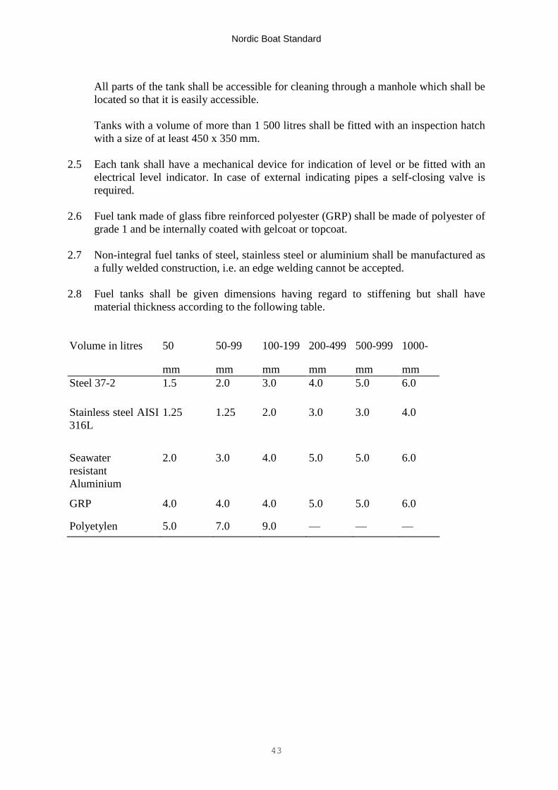
2.8 Fuel tanks shall be given dimensions having regard to stiffening but shall havematerial thickness according to the following table.
Volume in litres 50 50-99 100-199 200-499 500-999 1000-
mm mm mm mm mm mmSteel 37-2 1.5 2.0 3.0 4.0 5.0 6.0
Stainless steel AISI316L
1.25 1.25 2.0 3.0 3.0 4.0
SeawaterresistantAluminium
2.0 3.0 4.0 5.0 5.0 6.0
GRP 4.0 4.0 4.0 5.0 5.0 6.0
Polyetylen 5.0 7.0 9.0 — — —
Nordic Boat Standard
44
3 FUEL LINES
3.1 Fuel lines shall normally be pipes made of steel or copper. Short hose sections maybe used provided that they comply with the requirements in chapter MC8 orISO/DIS 84 69 (Small Craft-Non-Fire Resistant Fuel Hoses) and be marked acc-ordingly.
3.2 Each permanently mounted tank shall have separate filling and ventilation lines.The outlet of the ventilation line shall have flame arresters and be so arranged thatwater normally cannot flow into the tank. The filling line shall have an internaldiameter of at least 38 mm and the ventilation line at least 12 mm.
3.3 A shut-off valve shall be fitted in the fuel line as close as possible to the tank. Thevalve shall be possible to close from an accessible place above deck. The valveshall be fire resistant.
3.4 A fuel line shall be properly clamped and protected so that it is not exposed tomechanical damage or wear. Pipes and hoses shall be arranged with sufficientexpansion bends. Metallic components in a fuel line must not be combined so thatthey give rise to a damaging corrosion.
Details assembled in a piping system shall be of the same standard.
3.5 Connections of hoses shall be arranged in an appropriate way. If hose clamps areused, double clamps shall be fitted at each coupling. Hose fittings shall be ofsufficient length and shall be ribbed.
Hose clamps shall be made of acid resistant material.
3.6 After final installation the whole fuel system shall be subjected to a test for tight-ness with an overpressure of at least 0.02 N/mm. The tightness test may be carriedout with air and soapy water.
Nordic Boat Standard
45
PROPELLER SHAFTS AND PROPELLERS C10
Table of contents1 Propeller shaft2 Shaft brackets3 Free shaft lengths
1 PROPELLER SHAFTS
1.1 The shaft diameter shall comply with the engine manufacturer'srequirements but shall be at least
d = 3√p/r mm
where
p is the maximum continuous power in kWr propeller revolutions per secondk = 30 for carbon steel
23 for AISI 316 austenitic stainless steel22 for AISI Y31 martensitic stainless steel18 for Hickal-Copper alloy K 50021 for AISI 429
1.2 Other shaft material shall be specially considered having regard to theseawater fatigue properties of the material.
1.3 Shaft penetrations in a watertight bulkhead shall be arranged so that thewatertight integrity and strength of the bulkhead is maintained.
2 SHAFT BRACKETS
2.1 The wall thickness of a shaft bearing shall be at least:
t = d + 230/32 mm
where d is the shaft diameter in mm.
The length of the shaft bearing shall be at least 3 d for bearings in sterntubes and 2 d for other brackets.
Nordic Boat Standard
46
2.2 One-armed shaft brackets shall have a minimum moment of resistance(section modulus) (W) at the bottom of the boat calculated according to thefollowing formula:
W = l * d2/(112 *σB)
where
l is the length of the shaft bracket in mmσB the tensile strength of the material.
At the propeller shaft the section modulus of the shaft bracket shall be atleast 60 per cent of the-above requirement.
3 FREE PROPELLER SHAFT LENGTHS
3.1 The distance between the shaft supports (bearings) must not be greater thanthat specified by the diagram.

Nordic Boat Standard
47
Nordic Boat Standard
48
ELECTRICAL INSTALLATIONS C11
Table of contents1 Scope2 System requirements3 Group composition4 Accessibility and marking5 Overcurrent protection6 Battery arrangement7 Drawing of wires and location of components8 Housing9 Cables and fittings
1 SCOPE
1.1 These requirements apply to direct current installations with a rated voltage up to50 V. For other installations reference is made to the requirements of the nationaladministration.
1.2 The Standard does not cover electrical components installed in propulsion enginesor auxiliary engines or equipment in apparatus such as radio apparatus, electricalmotors, signal horns, instruments, etc. If, however, it can be established that suchapparatus are defective from a safety point of view, improvement or replacementmay be required.
1.3 The Standard does not cover protective measures against electromagneticinfluence on persons from apparatus such as radars and viewing screens.
2 SYSTEM REQUIREMENTS
2.1 Systems shall normally be installed as insulated two conductor systems.
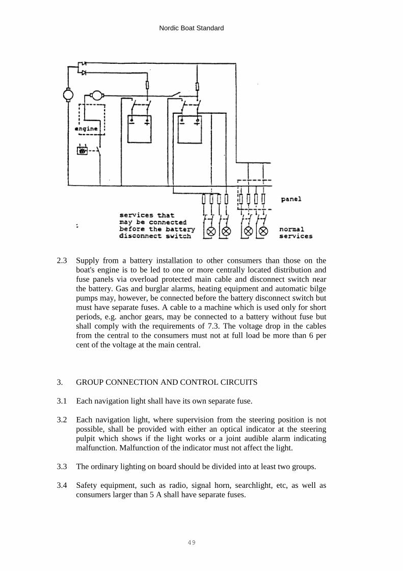
2.2 For propulsion engines with a power less than 100 kW it is permitted that theengine be used as conductor during start.
The figure below shows an example where the engine is used as conductor duringstart and where either of the batteries can be used to start the engine.
Nordic Boat Standard
49
2.3 Supply from a battery installation to other consumers than those on theboat's engine is to be led to one or more centrally located distribution andfuse panels via overload protected main cable and disconnect switch nearthe battery. Gas and burglar alarms, heating equipment and automatic bilgepumps may, however, be connected before the battery disconnect switch butmust have separate fuses. A cable to a machine which is used only for shortperiods, e.g. anchor gears, may be connected to a battery without fuse butshall comply with the requirements of 7.3. The voltage drop in the cablesfrom the central to the consumers must not at full load be more than 6 percent of the voltage at the main central.
3. GROUP CONNECTION AND CONTROL CIRCUITS
3.1 Each navigation light shall have its own separate fuse.
3.2 Each navigation light, where supervision from the steering position is notpossible, shall be provided with either an optical indicator at the steeringpulpit which shows if the light works or a joint audible alarm indicatingmalfunction. Malfunction of the indicator must not affect the light.
3.3 The ordinary lighting on board should be divided into at least two groups.
3.4 Safety equipment, such as radio, signal horn, searchlight, etc, as well asconsumers larger than 5 A shall have separate fuses.
Nordic Boat Standard
50
4 ACCESSIBILITY AND MARKING
4.1 Batteries, cables and other electrical components shall be located so thatthey can be supervised and maintained also when the boat is in operation. Awiring diagram for the installation shall be supplied with the boat.
4.2 All markings shall be made with permanent marking signs with durable text.
4.3 Connected equipment and rated current shall be stated at each fuse. Thecircuit number given in the wiring diagram shall correspond to the circuitnumber marking on the fuse base. A wiring diagram shall be posted in thecentral on the inside of the door or hatch. Each group shall be accessible forinsulation measurement.
4.4 Measuring instruments, switches, signal lamps, etc in apparatus cabinetsshall be fitted with clear marking.
4.5 Socket outlets shall have marking signs indicating voltage and type ofcurrent. In boats with only 12 or 24 V direct current socket outlets withoutmarking are accepted.
4.6 Conductors and multiconductors shall have a durable marking e.g. withcolours, so that they can be identified with the aid of the wiring diagram.
4.7 Marking shall indicate the use of each battery and how a possible transferbetween batteries is made.
5 OVERLOAD PROTECTION
5.1 Cables shall be so dimensioned that they under normal operation conditions,will not reach a hazardous temperature or be damaged by thermal ormechanical loads at short circuit. A connection between battery and startingmotor shall not be provided with a fuse. For connection battery startingmotor and generator-battery the motor manufacturer's recommendationsinstructions concerning cable area should be complied with, the voltage dropmust, however, not be more than 8 per cent.
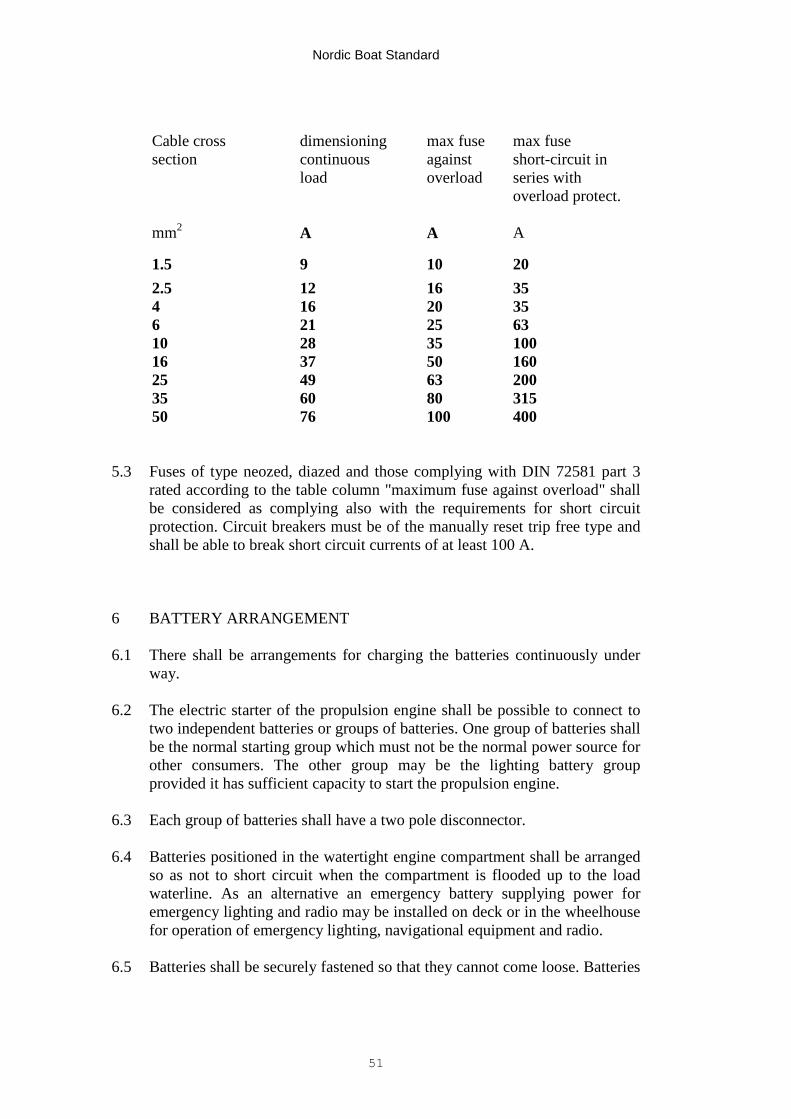
5.2 Overload protection shall protect the cables against overload and at shortcircuit break the current within a period of not more than five seconds inaccordance with the table below. The overload protection shall be placed inthe central and near the battery respectively. Each group shall be protectedat both poles. Cables which only transfer signals to instruments or the likemay have a smaller cross section than the smallest in the table.
Nordic Boat Standard
51
Cable crosssection
dimensioningcontinuousload
max fuseagainstoverload
max fuseshort-circuit inseries withoverload protect.
mm2 A A A
1.5 9 10 202.5 12 16 354 16 20 356 21 25 6310 28 35 10016 37 50 16025 49 63 20035 60 80 31550 76 100 400
5.3 Fuses of type neozed, diazed and those complying with DIN 72581 part 3rated according to the table column "maximum fuse against overload" shallbe considered as complying also with the requirements for short circuitprotection. Circuit breakers must be of the manually reset trip free type andshall be able to break short circuit currents of at least 100 A.
6 BATTERY ARRANGEMENT
6.1 There shall be arrangements for charging the batteries continuously underway.
6.2 The electric starter of the propulsion engine shall be possible to connect totwo independent batteries or groups of batteries. One group of batteries shallbe the normal starting group which must not be the normal power source forother consumers. The other group may be the lighting battery groupprovided it has sufficient capacity to start the propulsion engine.
6.3 Each group of batteries shall have a two pole disconnector.
6.4 Batteries positioned in the watertight engine compartment shall be arrangedso as not to short circuit when the compartment is flooded up to the loadwaterline. As an alternative an emergency battery supplying power foremergency lighting and radio may be installed on deck or in the wheelhousefor operation of emergency lighting, navigational equipment and radio.
6.5 Batteries shall be securely fastened so that they cannot come loose. Batteries
Nordic Boat Standard
52
constructed so that they may leak under heavy heeling shall be placed in aliquid tight case of a material which is resistant to the electrolyte.
6.6 Battery installations of more than 5 kWh, equivalent to 208 Ah at 24 V and416 Ah at 12 V shall be placed in a separate compartment with ventilation tothe open air. The arrangement shall be such that the air circulation is notblocked.
7 CABLE DRAWING AND PLACING OF COMPONENTS
7.1 Cables shall be securely clamped or run in conduits. The conduits shalleither be properly fastened by clamps or be matted in. Direct embedding ofcables in GRP laminates is not accepted. Cables must not be fastened directto tanks, oil pipes or water pipes, etc.
7.2 Cables shall be located in such a way that they are protected against heat.Cables which can be subjected to mechanical wear shall be armoured orplaced in tubing. The pipes shall either be properly clamped or protected bytubing. Cables positioned below machinery or flooring shall be protected bytubing or equivalent. Tubing for cables shall be positioned so that possiblewater or condensation will flow out of the tube. Cable penetrations of decksor watertight bulkheads shall be watertight. Cable entrances should be frombelow or from the side.
7.3 The following cables shall be separate insulated single conductors whichshall be located so that they are well protected against mechanical damage:
generator – battery;battery – starting motor;battery – central.
Where these cables are fastened to an electrically conductive material theyshall be single conductor cables or insulated single conductors in separatesheaths of insulating material.
7.4 Cable ends shall be securely connected in such a way that the conductors arenot damaged. Cable sheaths shall reach into the entrance to the connection.Cables which shall comply with the requirements of 7.3 should be connectedwith pressed on cable-thimbles with lock washer and nut. Other connectionsshall be made on terminals or with fixed clips.
7.5 Fuses or batteries must not be located in the same compartment as gasolinetanks or space with containers for substances which can emit explosivegases. Fuses must also not be located in a closed battery space. Switches andlighting fittings in such spaces shall be of explosion proof construction.
Nordic Boat Standard
53
8 ENCLOSURE PROTECTION
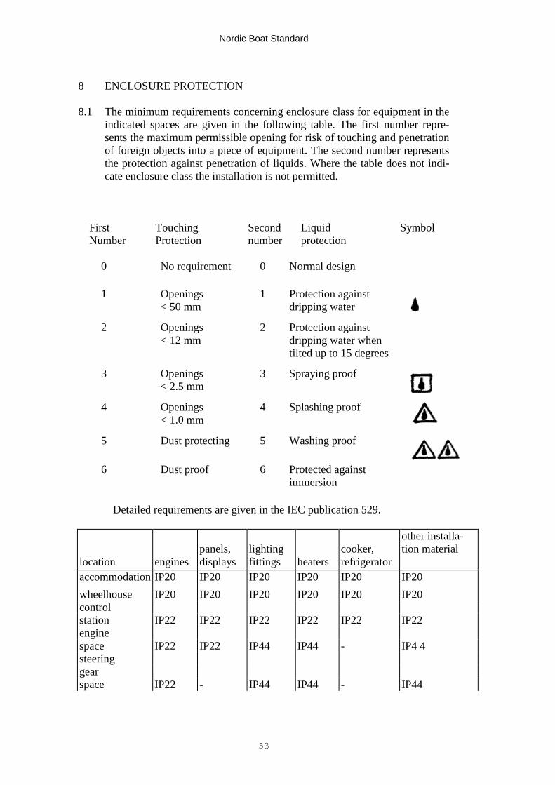
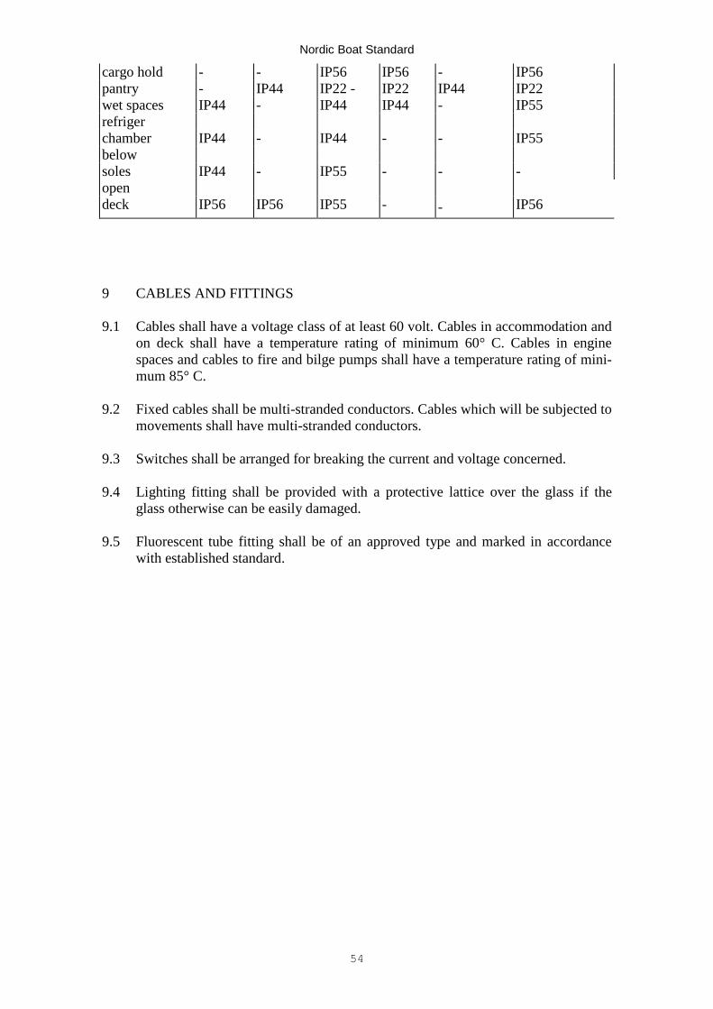
8.1 The minimum requirements concerning enclosure class for equipment in theindicated spaces are given in the following table. The first number repre-sents the maximum permissible opening for risk of touching and penetrationof foreign objects into a piece of equipment. The second number representsthe protection against penetration of liquids. Where the table does not indi-cate enclosure class the installation is not permitted.
First Touching Second Liquid SymbolNumber Protection number protection
0 No requirement 0 Normal design
1 Openings< 50 mm
1 Protection againstdripping water
2 Openings< 12 mm
2 Protection againstdripping water whentilted up to 15 degrees
3 Openings< 2.5 mm
3 Spraying proof
4 Openings< 1.0 mm
4 Splashing proof
5 Dust protecting 5 Washing proof
6 Dust proof 6 Protected againstimmersion
Detailed requirements are given in the IEC publication 529.
location enginespanels,displays
lightingfittings heaters
cooker,refrigerator
other installa-tion material
accommodation IP20 IP20 IP20 IP20 IP20 IP20
wheelhouse IP20 IP20 IP20 IP20 IP20 IP20controlstation IP22 IP22 IP22 IP22 IP22 IP22enginespace IP22 IP22 IP44 IP44 - IP4 4steeringgearspace IP22 - IP44 IP44 - IP44
Nordic Boat Standard
54
cargo hold - - IP56 IP56 - IP56pantry - IP44 IP22 - IP22 IP44 IP22wet spaces IP44 - IP44 IP44 - IP55refrigerchamber IP44 - IP44 - - IP55belowsoles IP44 - IP55 - - -opendeck IP56 IP56 IP55 - - IP56
9 CABLES AND FITTINGS
9.1 Cables shall have a voltage class of at least 60 volt. Cables in accommodation andon deck shall have a temperature rating of minimum 60° C. Cables in enginespaces and cables to fire and bilge pumps shall have a temperature rating of mini-mum 85° C.
9.2 Fixed cables shall be multi-stranded conductors. Cables which will be subjected tomovements shall have multi-stranded conductors.
9.3 Switches shall be arranged for breaking the current and voltage concerned.
9.4 Lighting fitting shall be provided with a protective lattice over the glass if theglass otherwise can be easily damaged.
9.5 Fluorescent tube fitting shall be of an approved type and marked in accordancewith established standard.
Nordic Boat Standard
55
ACCOMMODATION C12
Table of contents1 Toilets2 Ventilation3 Fresh water system
1 TOILETS
1.1 Closed boats with a length overall of more than 8 metres shall be provided with atleast one toilet.
1.2 All toilet spaces shall have a lockable door and be well lightened up. Each spaceshall be provided with a wash basin with water and drain.
2 VENTILATION
2.1 Accommodation spaces shall be so ventilated as to ensure sufficient supply andexhaust of air when doors, sidescuttles, windows and similar apertures are closed.
2.2 The ventilation apertures for inlet and outlet of air shall be so located as to obtainbest possible ventilation.
2.3 Cowl for fresh air supply shall be located so that there is no danger of inlet ofharmful combustion products. By natural ventilation the channels shall be as short aspossible with a minimum of bend.
2.4 By natural ventilation the sectional area of flow of supply and exhaust channels shallbe a minimum of 7.5 square centimetres per seat in the room or equivalent.
2.5 A cowl with exhaust into the open air shall be mounted above any cooking place.The channel shall be provided with a ventilation fan.
2.6 Toilet spaces shall be provided with separate exhaust to the open air.
3 FRESH WATER SYSTEMS
3.1 Fresh water tanks shall be readily accessible for cleaning.
3.2 Tanks shall have an inspection hatch with a diameter of at least 150 mm.
3.3 Fresh water tanks shall be capable of being drained through a valve at the lowestpoint of the tank or through a suction line. The suction line shall end in a well in thebottom of the tank.
Nordic Boat Standard
56
PROTECTION OF PERSONNEL C13
Table of contents1 Non-slip arrangements on deck2 Rails and hand holds3 Sharp edges4 Non-slip arrangement in engine spaces5 Safety at moving and hot items6 Emergency exits7 Boarding arrangements
1 NON-SLIP ARRANGEMENTS ON DECK
1.1 Open decks, the space around winches and windlasses and spaces where personscan be expected to walk or stay shall be provided with non-slip surfaces in order toget a safe foothold.
2 RAILS AND HAND HOLDS
2.1 Open decks intended to be used by persons shall be equipped with a bulwark orfixed rail. The rail may be portable if necessary for the operation of the boat.
2.2 The height of bulwark and rail shall be at least 750 mm. A rail must not have anopening greater than 230 mm below the lowest bar. The distance between the barsotherwise must not be more than 330 mm.
2.3 All boats shall be provided with the necessary hand holds or other arrangements forpersons to keep a firm hold to protect themselves from being injured.
3 SHARP EDGES
3.1 Sharp edges which can cause injuries to persons are not permitted at places wherepersons shall move or stay.
4 NON-SLIP ARRANGEMENTS IN ENGINE SPACES
4.1 Surfaces where persons can walk shall be non-slip and must not absorb oil. Soles(floorings) shall be firmly mounted.
Nordic Boat Standard
57
5 SAFETY AT MOVING AND HOT ITEMS
5.1 If persons stay or move near machines and apparatus with hot or moving parts,these shall be arranged so that risk for injuries is avoided. Exhaust pipes with asurface temperature of more than 80° C must not be easily accessible for touching.
Rotating parts shall be shielded so that clothes or the like are not entrapped.
5.2 Wire reels shall be so arranged that the wire end does not strike up against theperson who serves at the reel.
6 EMERGENCY ESCAPES
6.1 All spaces in which persons can be present shall have two exits. Only one exit can,however, be accepted for small rooms provided that it will not be blocked by a firein the engine room, pantry or the like.
6.2 The exits shall be as far as possible from each other and suitable for use in anemergency. Ladders, steps and hand holds are required if the exit otherwise is noteasily accessible.
6.3 The opening of exits shall be at least 450 x 450 mm or have a diameter of at least450 mm.
6.4 The exits shall easily be capable of being opened from the inside without use oftools. Sliding covers shall be provided with hand hold on the inside.
The exit shall also be capable of being opened from the outside. The use of a loosehandle, fire axe or equivalent for opening is, however, accepted if such devices areavailable at the central place in the boat, e.g. in the wheelhouse.
6.5 If access to an exit passes through another enclosed room, doors to such rooms maybe lockable only if they have a kick-plate which can be removed in the direction ofescape.
7 BOARDING ARRANGEMENTS
7.1 All boats shall have a permanently mounted rescue ladder or equivalent suitablearrangements which will enable a person who has fallen overboard to get on boardagain. Convertible rope ladders are not regarded as permanently mounted. Thelowest step shall be arranged at least 300 mm below the waterline.
Nordic Boat Standard
58
FIRE SAFETY C14
Table of contents1 Installation of cooker2 LPG installation3 Structural fire protection4 Fixed fire extinguishing system
1 INSTALLATION OF COOKER
1.1 Cooler constructed so that fuel can be spilled during filling or so that fuel can leakif the flame goes out shall be placed in or over a liquid tight case. The sides of thecase shall have a height of at least 20 mm.
1.2 Oil fired heaters with an open burning shall be provided with a valve whichautomatically close the oil supply if a fire arises in the apparatus.
1.3 LPG fired apparatus shall be provided with a shut-off valve. The valve shall beaccessible near the apparatus and be capable of being manoeuvred in case of a firein the apparatus. If the valve on the bottle is easily accessible near the apparatus theshut-off valve is not required.
1.4 LPG fired combustion apparatus other than ovens shall be of the sealed combustionchamber type and be installed so that the combustion system is completelyseparated from the air in the boat. Spaces in which a gas fired combustion apparatusis installed shall be ventilated.
1.5 Combustion apparatus shall be installed so that the surrounding parts will not besubjected to hazardous heating. Combustion material must not be subjected to ahigher temperature than 80° C. The figure below shows the distances from an openflame which are permitted and when control of heating of combustible materialshall be carried out. Protection against heating of combustible material may beachieved through shielding with non combustible material which is thermally insu-lated from the combustible material.
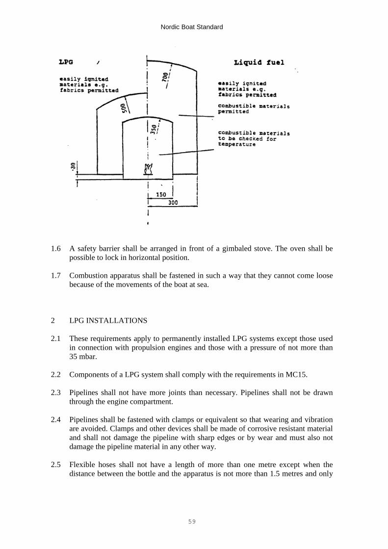
Nordic Boat Standard
59
1.6 A safety barrier shall be arranged in front of a gimbaled stove. The oven shall bepossible to lock in horizontal position.
1.7 Combustion apparatus shall be fastened in such a way that they cannot come loosebecause of the movements of the boat at sea.
2 LPG INSTALLATIONS
2.1 These requirements apply to permanently installed LPG systems except those usedin connection with propulsion engines and those with a pressure of not more than35 mbar.
2.2 Components of a LPG system shall comply with the requirements in MC15.
2.3 Pipelines shall not have more joints than necessary. Pipelines shall not be drawnthrough the engine compartment.
2.4 Pipelines shall be fastened with clamps or equivalent so that wearing and vibrationare avoided. Clamps and other devices shall be made of corrosive resistant materialand shall not damage the pipeline with sharp edges or by wear and must also notdamage the pipeline material in any other way.
2.5 Flexible hoses shall not have a length of more than one metre except when thedistance between the bottle and the apparatus is not more than 1.5 metres and only
Nordic Boat Standard
60
one apparatus is connected to the bottle. Rubber hoses, if used, shall be accessiblefor inspection.
2.6 The space for the bottle shall have arrangements for securing the bottle againstmovement. A regulator which is not designed for mounting direct on the bottle shallbe fixed mounted in the same space. It shall not be possible to use the bottle spacefor storage of other equipment. Spaces for spare bottles, both filled and empty, shallcomply with the same requirements as those for bottles. Safety devices shall bemounted in such a way that they can withstand the movements which normally canbe expected at sea. Systems with two connected bottles shall have a valve forchanging over from one bottle to the other. This valve will not substitute the bottleshut-off valve.
2.7 The space for LPG bottles, regulator and safety devices on open deck, on the top ofa superstructure, outside the cockpit well or an enclosed space shall be a case withdirect ventilation to the open air.
2.8 A space for an LPG bottle, gas regulator and safety devices below deck and in thecockpit shall be gas-tightly separated from the accommodation and capable ofbeing opened only from above and arranged so that gas cannot flow into the boat.The space shall be positioned above the waterline and shall, if covered, be rapidlyaccessible and capable of being opened without tools so that the bottle valve can bemanoeuvred and so that the system can be pressure tested for tightness and apressure gauge be read, if fitted.
The space shall have a ventilation opening in the bottom with an inner diameter ofat least 12.5 mm which leads to the outside of the boat without pockets through thehull to a point lower than the bottom of the space but above the waterline. Theopening must be located at least 500 mm from other hull openings which lead intothe boat.
2.9 The system shall after final completion be controlled in respect of leakage, usingsoapy water or a detergent solution at all couplings and at possible leakage warningdevices. Leakage must not exist. The pipeline shall before it is connected to the gasregulator or to the leakage warning device, if fitted, be pressure tested with air at atleast 35 kPa. Leakages must not exist.
3. STRUCTURAL FIRE PROTECTION
3.1 Insulation materials which are used and their surfaces shall have an oxygen indexof at least 21.
3.2 Insulation materials in engine rooms shall be covered by a surface layerimpermeable to oil and oil mist.
3.3 Oil tanks and bilge water tanks located totally or partly above the flooring in the
Nordic Boat Standard
61
engine room shall be insulated with a hard mineral wool block with a thickness ofat least 15 mm or with expanding, fire protecting paint with equivalent insulationeffect. The sides which are protected by the hull need not be insulated.
4. FIXED FIRE EXTINGUISHING SYSTEM
4.1 Boats with a length overall greater than 8 metres shall have a fixed fireextinguishing system in the engine room. In closed and partly covered boats a firealarm system is in addition required for the engine room. The signal device shall belocated at the steering place.
4.2 The requirements below apply to an extinguishing system with carbon dioxide asthe extinguishing medium. Other extinguishing media which give equivalent safetyand function are also accepted.
4.3 The extinguishing system shall be able to be released manually only. The releasedevice shall be centrally positioned in the boat outside the engine room and the tankspace and be protected against splash water and risk, for unintentional release. Aninstruction shall be fitted at the release place.
4.4 The bottles for extinguishing medium shall be positioned in -a space where seawater splash, mechanical damage or temperatures above 50°C are not expected.Bottles must not be placed in the engine room.
4.5 Pipelines and nozzles shall be designed and placed so that an even distribution ofthe extinguishing medium is achieved. The amount of extinguishing medium anddischarge time shall be so adapted that an effective extinction is achieved.
4.6 The amount of carbon dioxide shall be 1.5 kg per cubic metre of the gross volumeof the engine room, however, at least 2 kg. At least half the filling ratio shall beachieved in not more than ten seconds.
4.7 Ventilation openings and their closing devices shall be so arranged that a damagingoverpressure will not arise at release of the extinguishing system.
4.8 The engine room and spaces for carbon dioxide bottles and other parts of thesystem where leakage can occur shall be separated in such a way that leaking gascannot penetrate into spaces for personnel which can be closed. Spaces for bottlesshall have ventilation direct to the open air.
Nordic Boat Standard
62
LIFTING GEARS C15
Table of contents1 Scope2 Measures against overload3 Documentation of strength
1 SCOPE
1.1 These requirements apply to power driven lifting gears.
2 MEASURES AGAINST OVERLOAD
2.1 Lifting gears shall be so arranged that they without engagement with tools makeit impossible
- to lift a bigger load than that for which the gear is constructed; and- to expose the boat to a greater heeling moment than that permitted by the
stability requirements.
A lifting gear which is lifting the load with a wire shall be designed so that thewire cannot be overloaded when the hook reaches its innermost position.
2.2 The greatest permitted load shall be marked at a clearly visible place on thelifting gear. At least three different loads with the corresponding reach-outswhich in the most unfavourable position give a permitted heeling angle shall beindicated. The marking may in case of automatic load limitation indicatedifferent greatest permitted load for different crane positions. Other markingswhich can be mixed up with that required are not allowed.
3 DOCUMENTATION OF STRENGTH
3.1 For each lifting gear documentation showing for which load it has been appr-oved by the authorized testing body shall be provided.
3.2 Calculations which prove that the safety factor for metal is at least 5 and forglass reinforced polyester at least 7 is required for the lifting gear fastening andthe part of the boat which is affected.
Nordic Boat Standard
63
MOORING AND ANCHORING EQUIPMENT C16
Table of contents1 Bollards and fairleads2 Anchoring equipment, etc
1 BOLLARDS AND FAIRLEADS
1.1 The boat shall be provided with approved bollards according to chapter MC16 andhawsepipes arranged so that the boat can be anchored, tow other ships, be towedand moored satisfactorily.
1.2 All boats shall have at least one mooring cleat forward and one aft. When twocleats are fitted forward or aft they shall be located as near as possible to boatsides. For larger boats additional mooring cleats may be required.
1.3 One cleat forward and one aft shall be placed in such a way that towing ispossible. If a towing cleat mounted on the stern is easily accessible it can beapproved also as a mooring cleat in open boats without a deck forward.
1.4 Mooring cleats and their mountings shall be strongly designed and mounted. Thecleats and their mountings shall be strongly designed and mounted. The cleats andtheir mountings shall be capable of withstanding a tensile load (P) in thelongitudinal direction as follow:
P = 50 * Δ/Loa N
where Δ is the displacement fully loaded in kg.
1.5 Appropriate reinforcements shall be provided where the cleats are fastened. Bolts,nuts and other mounting details shall be made of corrosion resistant materials.
1.6 Mooring cleats shall either be welded or mounted with through bolts. Largewashers shall be fitted below the nuts and the nuts shall be locked.
2 AHCHORING EQUIPMENT
2.1 The boat shall be provided with anchoring equipment at least according to thefollowing diagrams. The equipment shall be arranged in such a way that it ispossible to anchor rapidly and reliably.
2.2 The anchor weight may be distributed on two anchors one of which must have atleast 2/3 of the required weight. The required anchor weights are based on
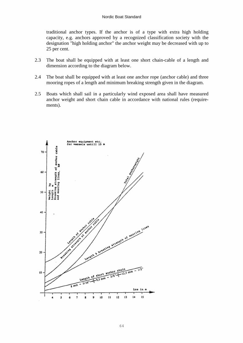
Nordic Boat Standard
64
traditional anchor types. If the anchor is of a type with extra high holdingcapacity, e.g. anchors approved by a recognized classification society with thedesignation "high holding anchor" the anchor weight may be decreased with up to25 per cent.
2.3 The boat shall be equipped with at least one short chain-cable of a length anddimension according to the diagram below.
2.4 The boat shall be equipped with at least one anchor rope (anchor cable) and threemooring ropes of a length and minimum breaking strength given in the diagram.
2.5 Boats which shall sail in a particularly wind exposed area shall have measuredanchor weight and short chain cable in accordance with national rules (require-ments).