Embed Size (px)
Citation preview
Available online at www.CivileJournal.org
Civil Engineering Journal
Vol. 5, No. 7, July, 2019
1440
Non-linear Analysis of Slender High Strength Concrete Column
Ernesto Fenollosa a*, Iván Cabrera a, Verónica Llopis b, Adolfo Alonso a a Tenure Professor, Ph.D., Department of Continuum Mechanics and Theory of Structures, Universitat Politècnica de València, Cno. de
Vera s/n, Valencia 46022, Spain.
b Professor, Ph.D., Department of Continuum Mechanics and Theory of Structures, Universitat Politècnica de València, Cno. de Vera
s/n, Valencia 46022, Spain.
Received 25 April 2019; Accepted 02 July 2019
Abstract
This article shows the influence of axial force eccentricity on high strength concrete columns design. The behavior of
columns made of normal, middle and high strength concrete with slenderness values between 20 and 60 under an eccentric
axial force has been studied. Structural analysis has been developed by means of software which considers both geometrical
and mechanical non-linearity. The sequence of points defined by increasing values of axial force and bending moment
produced by eccentricity has been represented on the cross-section interaction diagram until failure for each tested column.
Then, diagrams depicting the relationship between failure axial force and column's slenderness have been drawn. The loss
of bearing capacity of the member for normal and middle strength columns when compared with the bearing capacity of
their cross-section is more noticeable as axial force eccentricity assumes higher values. However, this situation reverses
for high strength columns with high slenderness values. On the basis of results obtained, the accuracy level for the moment
magnifier method was checked. Despite the good concordance in most of the cases, it was verified that the moment
magnifier method leads to excessively tight results for high strength concrete columns with high slenderness values. In
these specific cases, a coefficient which amends the column rigidity is proposed so as to obtain safer values.
Keywords: Columns; Axial Force; High Strength Concrete; Non-linear Analysis; Moment Magnifier Method.
1. Introduction
Reinforced concrete rigid frames are the most widely employed structural system. They are composed by columns
and beams. Columns are the structural elements whose prevailing internal force is an axial load which can be combined
with one or two bending moments around two orthogonal axis.
Since the mid-twentieth century they have been targeted in many researches whose results, after being contrasted
with pilot testing, have led to several calculation methods. In the case of short columns whose strength depends only on
the bearing capacity of their section, we should mention the method proposed by Bresler [1] and more recently Hsu [2].
Gradual technological development has enabled the production of concretes with a higher strength to compression
stress. The use of columns made of high strength concrete (HSC) in high-rise buildings reduces their section and
increases the available space around them. The reduction of the cross section caused by the use of high strength concrete
leads to slender columns whose bearing capacity is basically conditioned by their length. Therefore, a thorough analysis
of second order effects derived from both the P- effect and the materials mechanic non-linearity is required.
* Corresponding author: [email protected]
http://dx.doi.org/10.28991/cej-2019-03091343
© 2019 by the authors. Licensee C.E.J, Tehran, Iran. This article is an open access article distributed under the terms and conditions of the Creative Commons Attribution (CC-BY) license (http://creativecommons.org/licenses/by/4.0/).
Civil Engineering Journal Vol. 5, No. 7, July, 2019
1441
In order to know the first and more interesting theoretical and experimental studies about slender reinforced concrete
columns, we can consult those done by Mavichak and Furlong [3] and Al-Noury and Chen [4]. However not only the
concrete strength but also the slenderness values taken into consideration are the typical figures from those periods (fc<50
MPa and < 50), which are lightly smaller than those reached nowadays.
Studies about slender reinforced concrete columns made of HSC are much more recent but less often. Kim and Yang
brought forth an experimental study with columns whose involved variables were slenderness, concrete strength and
steel ratio [5]. Nevertheless, the axial force was applied with the same eccentricity on the pillar in all the cases tested.
Interest in a deeper knowledge on the behavior of these complex structural elements has currently increased. Recently
lab tests have been carried out not only on NSC slender columns [6] but also on HSC short [7] and slender columns [8,
9]. Results of work of Barrera et al. [10] confirm that reduced axial load decreases for an increase of the concrete strength
and slenderness of the specimen. However, in this research axial force is always applied with different eccentricity values
on both bar ends.
Thus, the main objective of this article consists of researching the effect of the axial force eccentricity on the bearing
capacity reduction because of second order effects on slender columns made of low, medium and high strength concretes.
Results obtained have been compared with those from the application of the well-known moment magnifier method
contained in the ACI 318 [11] in order to determine its safety level. This method, when employed for NSC columns,
provides unsafe values in one of the laboratory tests (test S10-A1) carried out by Leite et al. [12]. This author points in
his conclusions that the accuracy of this method in HSC columns is lower than in NSC columns.
This work will widen our knowledge on this subject by taking into consideration columns with usual heights in
architectural building and by considering an axial force applied with the same eccentricity on both sides of the column.
It will also verify the accuracy of the moment magnifier method for HSC slender columns.
Structural analysis has been addressed with matrix stiffness method software which takes into account the second
order effects produced by not only the interaction between axial force and lateral displacements but also the materials
non-linear behavior. Loads application has been done in an incremental way following the procedure described by
McGuire [13].
Final results will help us to understand the behavior of such a complex structural element under several load scenarios.
2. Computer Assisted Testing Software
Complexity and high economical cost of laboratory tests on actual columns make them rather difficult. Alternatively,
several analytical methods so as to determine the failure load values for NSC and HSC columns can be employed. Some
of the most recent ones are those published by Agha and Rashid [14] and Abdel-Karim et al. [15]. Also, it is possible to
analyze a vast range of models in a reduced amount of time by means of advanced software which reproduces perfectly
the columns non-linear behavior [16]. The software and the assumptions used are described hereunder.
2.1. Assumptions
The calculation process assumes the ensuing hypothesis:
Plane cross sections strain remains plane (Navier’s Hypothesis). Hence strains are proportional to the distance
to the neutral axis.
There is deformational compatibility between steel and concrete along their contact surfaces.
Concrete’s shrinkage and creep effects and concrete’s tension strength are not to be taken into account.
Shear stresses effects are disregarded
2.2. Constitutive Equations for Materials
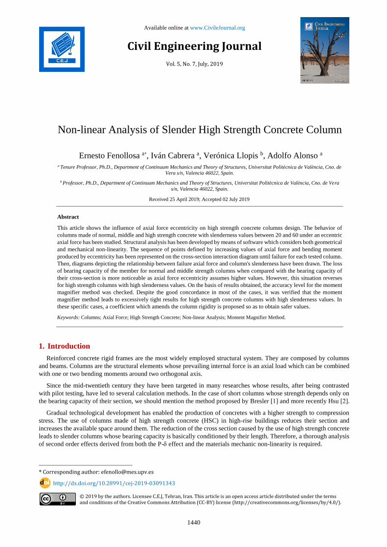
Non-linear structural design equation suggested by Eurocode 2 [17] has been employed in the case of concrete (Figure
1.a). Relationship between stresses and strains can be expressed by means of function (Equation 1):
·21
· 2
cm
c
f
(1)
Where
fcm=fck+8
(2)
Civil Engineering Journal Vol. 5, No. 7, July, 2019
1442
= c /c1 (3)
c1=0.7.𝑓𝑐𝑚0.31 2.8 (4)
=(1.05·Ec, nom)·c1 / fcm (5)
Ecm= 22. [(𝑓𝑐𝑚)/10]0.3 (6)
cu1=2,8+27·[(98-fcm)/100]4 (7)
As for rebars steel and according to Eurocode 2, a simplified stress-strain diagram constituted by just two branches
is employed (Figure 1.b). First branch arises from the origin with a slope whose value is Es until the characteristic yield
point of steel (fyk) removal is reached. Second branch is to be considered horizontal, until the ultimate strain with a value
of u=0.01 is reached.
a. Concrete b. Steel
Figure 1. Stress-strain diagrams
2.3. Structural Analysis for Columns
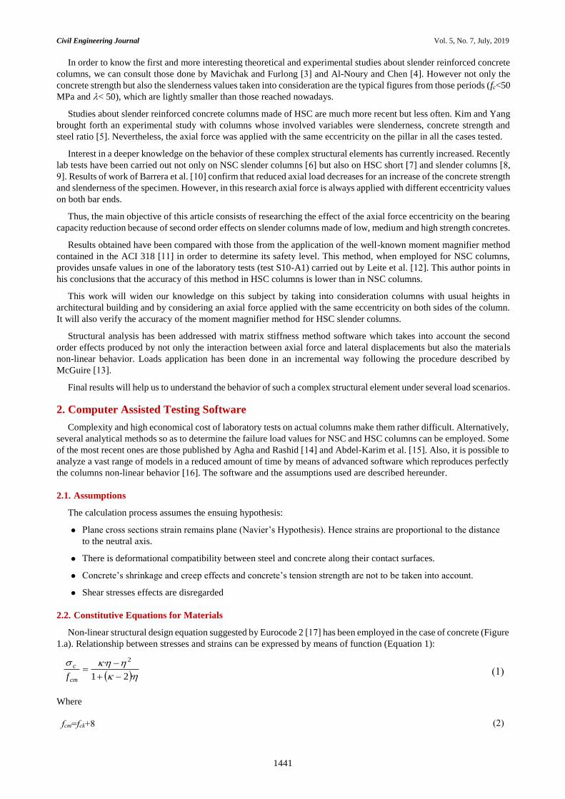
A reinforced concrete column bearing capacity is usually represented by means of interaction diagrams P-M. They
consist of the values of axial force (P) and bending moment (M) which produce the cross-section failure when being
applied simultaneously. Considering a linear behavior for the column, the load trajectory would be a line until failure is
reached (point A on the interaction diagram).
As for slender columns, this trajectory is a curve as long as second-order effects cannot be disregarded. Nonlinear
behavior of materials and the additional internal forces produced by the axial force being applied on geometry with
lateral deformations which cannot be dismissed (P- effect) produce a higher increase of bending moments which reduce
the ultimate load value.
Failure of the bar can occur in two different ways. Load trajectory can reach the interaction diagram, collapsing
because of strength failure. However, regarding very slender columns, collapse may happen because of instability, so
the load trajectory never can reach the interaction diagram (Figure 2).
Figure 2. Path of axial force / Bending moment values until failure of slender columns
fc
0.4 fc
c (<0)
cuc (<0)
c1
E c,nom
fc
0.4 fc
cuc1
s
s
0.01
fsk
tan E s-1
tan (10 E )s-1 -4
c1c1
1P
Axia
l F
orc
e (k
N)
2P
0P
P
3P
Short columnMaterial failure
Slender columnMaterial failure
Slender columnInestability failure
Bending Moment (kN m)
A
1M 2M 3M
B
C
M
Civil Engineering Journal Vol. 5, No. 7, July, 2019
1443
Most of the reinforced concrete columns employed in building structures collapse because of strength failure as long
as slenderness ratios are lower than the critical values which produce instability [18, 19]. But nowadays the employment
of high strength concrete in building structures enables smaller cross sections for the columns. That means higher
slenderness values and makes more likely the chance of failure because of instability.
Structural analysis was developed by means of non-linear calculation software named ANGLE [20]. According to
the method proposed for Wang and Hsu [21], the beam-column geometrical model defined by the different bars directrix
was discretized a series of bar stretches whose nodes initial coordinates were obtained. Axial force with a pre-established
eccentricity was applied progressively in several load stages until the bar failure.
Geometrical non-linearity has been taken into account at each stage by considering in the stiffness matrix the
deformed geometry corresponding to the previous stage. The process looking for the structure’s balance within the
different load stages was developed by means of the Newton-Raphson method.
Mechanical non-linearity has its influence on the stiffness modulus (E·I) to be considered in the stiffness matrix.
Because of the different materials non-linear behavior its determination requires applying some iterative process in order
to find the cross-section equilibrium. Within this work the procedure developed by Fenollosa et al. [22] has been used.
It consists of two linked loops. First one locates the strains plane curvature by means of axial forces balance. Second
one locates neutral axis by bending moments balance. Once the cross-section equilibrium was achieved, stiffness
modulus was deduced helped by the expression E·I=M/.
2.4. Geometry and Configuration
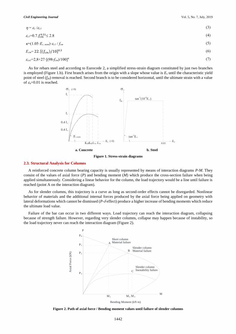
Thirty-six different models for columns with square-shaped cross section measuring 45×45 cm and reinforced with
8 bars with a diameter of 20 mm placed in the corners with a reinforcement mechanical cover of 40 mm have been tested
(Figure 3 left). Rebars amount implies a relation ρ=1.256% in relation to the concrete area.
Tested bars lengths are comprised between 3 and 8 meters. That includes the usual height that can be found in building
structures. They were modelled with pin joints at both ends and without taking into account any potential directrix
imperfections (Figure 3 right).
Figure 3. Analyzed columns cross section and loads application model
Bars mechanical slenderness has been defined by the equation =l0/i and ranges between 20 and 60, being l0 the
effective buckling length and i the bending radius for the gross section without taking cracking into account.
Two different eccentricities, with regard to the cross-section center of mass when applying the axial force, have been
considered: 20 and 100 mm.
Regarding concrete, three different strengths have been employed: 30 MPa for normal strength concrete (NSC), 60
MPa for middle strength concrete (MSC) and 90 MPa for high strength concrete (HSC). The characteristic values for
the three different types of concrete within this work are collected in Table 1.
Table 1. Characteristic values for concrete
fc (MPa) fcm (MPa) Ecm (MPa) εc1 εcu1
30 38 33.000 0.0022 0.0035
60 68 39.000 0.0026 0.0030
90 98 44.000 0.0028 0.0028
Steel, with a yield strength value of 500 MPa, a failure strain value of u=0.01 and a modulus of elasticity value of
Es=210.000 MPa, was employed.
450
450
40
Ø 20
L
e
Civil Engineering Journal Vol. 5, No. 7, July, 2019
1444
These parameters were taken into consideration when applying the materials constitutive equations, not only for the
determination of the stress value at each fiber when a certain strain is imposed, but also for introducing the failure
criterion when the ultimate strain has been reached.
3. Structural Analysis Results
Non-linear structural analysis for different columns has been carried out by means of the described mathematical
model. The path of the axial force and bending moment values until failure for each tested column has been represented
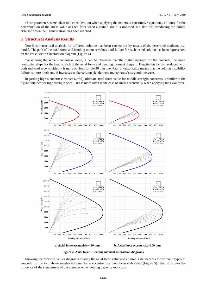
on the cross-section interaction diagram (Figure 4).
Considering the same slenderness value, it can be observed that the higher strength for the concrete, the more
horizontal shape for the final stretch of the axial force and bending moment diagram. Despite this fact is produced with
both analyzed eccentricities, it is more obvious for the 20 mm one. Path’s horizontality means that the column instability
failure is more likely and it increases as the column slenderness and concrete’s strength increase.
Regarding high slenderness values (λ=60), ultimate axial force value for middle strength concretes is similar to the
figure obtained for high strength ones. That is more often in the case of small eccentricity when applying the axial force.
a. Axial force eccentricity=20 mm b. Axial force eccentricity=100 mm
Figure 4. Axial force - Bending moment interaction diagrams
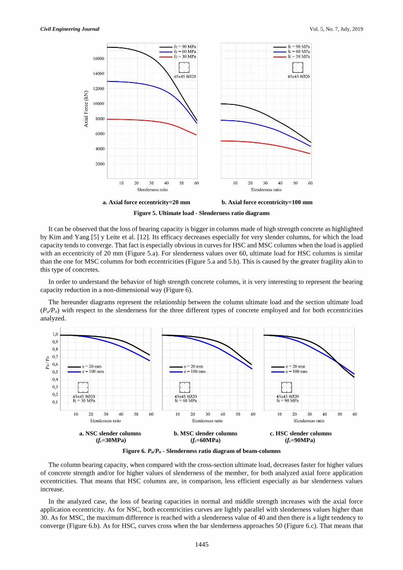
Knowing the previous values diagrams relating the axial force value and column’s slenderness for different types of
concrete for the two above mentioned axial force eccentricities have been elaborated (Figure 5). That illustrates the
influence of the slenderness of the member on its bearing capacity reduction.
Civil Engineering Journal Vol. 5, No. 7, July, 2019
1445
a. Axial force eccentricity=20 mm b. Axial force eccentricity=100 mm
Figure 5. Ultimate load - Slenderness ratio diagrams
It can be observed that the loss of bearing capacity is bigger in columns made of high strength concrete as highlighted
by Kim and Yang [5] y Leite et al. [12]. Its efficacy decreases especially for very slender columns, for which the load
capacity tends to converge. That fact is especially obvious in curves for HSC and MSC columns when the load is applied
with an eccentricity of 20 mm (Figure 5.a). For slenderness values over 60, ultimate load for HSC columns is similar
than the one for MSC columns for both eccentricities (Figure 5.a and 5.b). This is caused by the greater fragility akin to
this type of concretes.
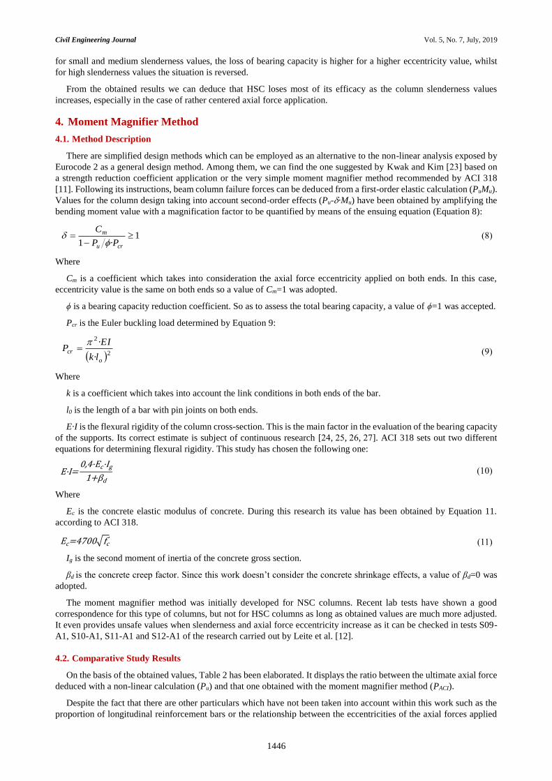
In order to understand the behavior of high strength concrete columns, it is very interesting to represent the bearing
capacity reduction in a non-dimensional way (Figure 6).
The hereunder diagrams represent the relationship between the column ultimate load and the section ultimate load
(Pu/Pn) with respect to the slenderness for the three different types of concrete employed and for both eccentricities
analyzed.
a. NSC slender columns b. MSC slender columns c. HSC slender columns (fc=30MPa) (fc=60MPa) (fc=90MPa)
Figure 6. Pu/Pn - Slenderness ratio diagram of beam-columns
The column bearing capacity, when compared with the cross-section ultimate load, decreases faster for higher values
of concrete strength and/or for higher values of slenderness of the member, for both analyzed axial force application
eccentricities. That means that HSC columns are, in comparison, less efficient especially as bar slenderness values
increase.
In the analyzed case, the loss of bearing capacities in normal and middle strength increases with the axial force
application eccentricity. As for NSC, both eccentricities curves are lightly parallel with slenderness values higher than
30. As for MSC, the maximum difference is reached with a slenderness value of 40 and then there is a light tendency to
converge (Figure 6.b). As for HSC, curves cross when the bar slenderness approaches 50 (Figure 6.c). That means that
Civil Engineering Journal Vol. 5, No. 7, July, 2019
1446
for small and medium slenderness values, the loss of bearing capacity is higher for a higher eccentricity value, whilst
for high slenderness values the situation is reversed.
From the obtained results we can deduce that HSC loses most of its efficacy as the column slenderness values
increases, especially in the case of rather centered axial force application.
4. Moment Magnifier Method
4.1. Method Description
There are simplified design methods which can be employed as an alternative to the non-linear analysis exposed by
Eurocode 2 as a general design method. Among them, we can find the one suggested by Kwak and Kim [23] based on
a strength reduction coefficient application or the very simple moment magnifier method recommended by ACI 318
[11]. Following its instructions, beam column failure forces can be deduced from a first-order elastic calculation (PuMu).
Values for the column design taking into account second-order effects (Pu-·Mu) have been obtained by amplifying the
bending moment value with a magnification factor to be quantified by means of the ensuing equation (Equation 8):
1·1
cru
m
PP
C
(8)
Where
Cm is a coefficient which takes into consideration the axial force eccentricity applied on both ends. In this case,
eccentricity value is the same on both ends so a value of Cm=1 was adopted.
ϕ is a bearing capacity reduction coefficient. So as to assess the total bearing capacity, a value of ϕ=1 was accepted.
Pcr is the Euler buckling load determined by Equation 9:
22
·
·
o
crlk
EIP
(9)
Where
k is a coefficient which takes into account the link conditions in both ends of the bar.
l0 is the length of a bar with pin joints on both ends.
E·I is the flexural rigidity of the column cross-section. This is the main factor in the evaluation of the bearing capacity
of the supports. Its correct estimate is subject of continuous research [24, 25, 26, 27]. ACI 318 sets out two different
equations for determining flexural rigidity. This study has chosen the following one:
E·I=0,4·Ec·Ig
1+βd
(10)
Where
Ec is the concrete elastic modulus of concrete. During this research its value has been obtained by Equation 11.
according to ACI 318.
Ec=4700√fc' (11)
Ig is the second moment of inertia of the concrete gross section.
βd is the concrete creep factor. Since this work doesn’t consider the concrete shrinkage effects, a value of βd=0 was
adopted.
The moment magnifier method was initially developed for NSC columns. Recent lab tests have shown a good
correspondence for this type of columns, but not for HSC columns as long as obtained values are much more adjusted.
It even provides unsafe values when slenderness and axial force eccentricity increase as it can be checked in tests S09-
A1, S10-A1, S11-A1 and S12-A1 of the research carried out by Leite et al. [12].
4.2. Comparative Study Results
On the basis of the obtained values, Table 2 has been elaborated. It displays the ratio between the ultimate axial force
deduced with a non-linear calculation (Pu) and that one obtained with the moment magnifier method (PACI).
Despite the fact that there are other particulars which have not been taken into account within this work such as the
proportion of longitudinal reinforcement bars or the relationship between the eccentricities of the axial forces applied
Civil Engineering Journal Vol. 5, No. 7, July, 2019
1447
on both ends of the bar, values of Pu/ PACI obtained are sufficiently close to those published by Mendis [28] and Leite et
al. [12] in their comparative works which included lab tests.
Table 2. Pu/PACI ratio for NSC, MSC and HSC slender columns
fc = 30 MPa fc = 60 MPa fc = 90 MPa
e=20mm e=100mm e=20mm e=100mm e=20mm e=100mm
3 m 1,006 1,019 1,014 1,029 1,017 1,030
4 m 1,013 1,031 1,031 1,055 1,034 1,049
5 m 1,024 1,047 1,060 1,080 1,055 1,056
6 m 1,034 1,054 1,100 1,088 1,052 1,092
7 m 1,045 1,058 1,125 1,085 1,026 1,081
8 m 1,086 1,058 1,117 1,070 0,991 1,048
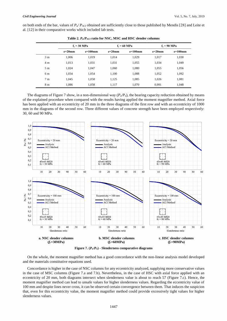
The diagrams of Figure 7 show, in a non-dimensional way (Pu/Pn), the bearing capacity reduction obtained by means
of the explained procedure when compared with the results having applied the moment magnifier method. Axial force
has been applied with an eccentricity of 20 mm in the three diagrams of the first row and with an eccentricity of 1000
mm in the diagrams of the second row. Three different values of concrete strength have been employed respectively:
30, 60 and 90 MPa.
a. NSC slender columns b. MSC slender columns c. HSC slender columns (fc=30MPa) (fc=60MPa) (fc=90MPa)
Figure 7. (Pu/Pn) - Slenderness comparative diagrams
On the whole, the moment magnifier method has a good concordance with the non-linear analysis model developed
and the materials constitutive equations used.
Concordance is higher in the case of NSC columns for any eccentricity analyzed, supplying more conservative values
in the case of MSC columns (Figure 7.a and 7.b). Nevertheless, in the case of HSC with axial force applied with an
eccentricity of 20 mm, both diagrams intersect when slenderness value is about to reach 57 (Figure 7.c). Hence, the
moment magnifier method can lead to unsafe values for higher slenderness values. Regarding the eccentricity value of
100 mm and despite lines never cross, it can be observed certain convergence between them. That induces the suspicion
that, even for this eccentricity value, the moment magnifier method could provide excessively tight values for higher
slenderness values.
Civil Engineering Journal Vol. 5, No. 7, July, 2019
1448
It is understandable that a higher concordance with the moment magnifier method can be found in the case of NSC
columns, meaning a sufficient safety margin, since this method was developed when the employ of concretes with this
range of strength was usual. The direct application for HSC columns must be done carefully.
4.3. Flexural Rigidity Value Revision
The equation proposed by the ACI 318 to get the E·I term, was obtained for normal strength concrete. Bonet et al.
[29] suggest its revision for application to HSC columns. The work of Lee et al. [30] shows that expressions for
estimating the elastic modulus for concrete proposed by codes Eurocode 2 and ACI 318 provide higher values than those
obtained by means of laboratory tests for middle and high strength concretes. Tikka and Mirza [31] suggest the use of
alternative equation to the one proposed by ACI 318 in order de determine the value of EI. In that equation this value
depends on the end eccentricity ratio (e/h) which means an EI value which is not only variable but also non-linear.
In order to obtain similar safety values in HSC columns than in NSC and MSC columns when the moment magnifier
method is applied, an additional coefficient (γ) (Equations 12 and 13) is suggested. This one reduces the flexural rigidity
for slenderness values higher than 50:
·1
··4,0·
d
gc IEIE
(12)
Where:
1·4
501
(13)
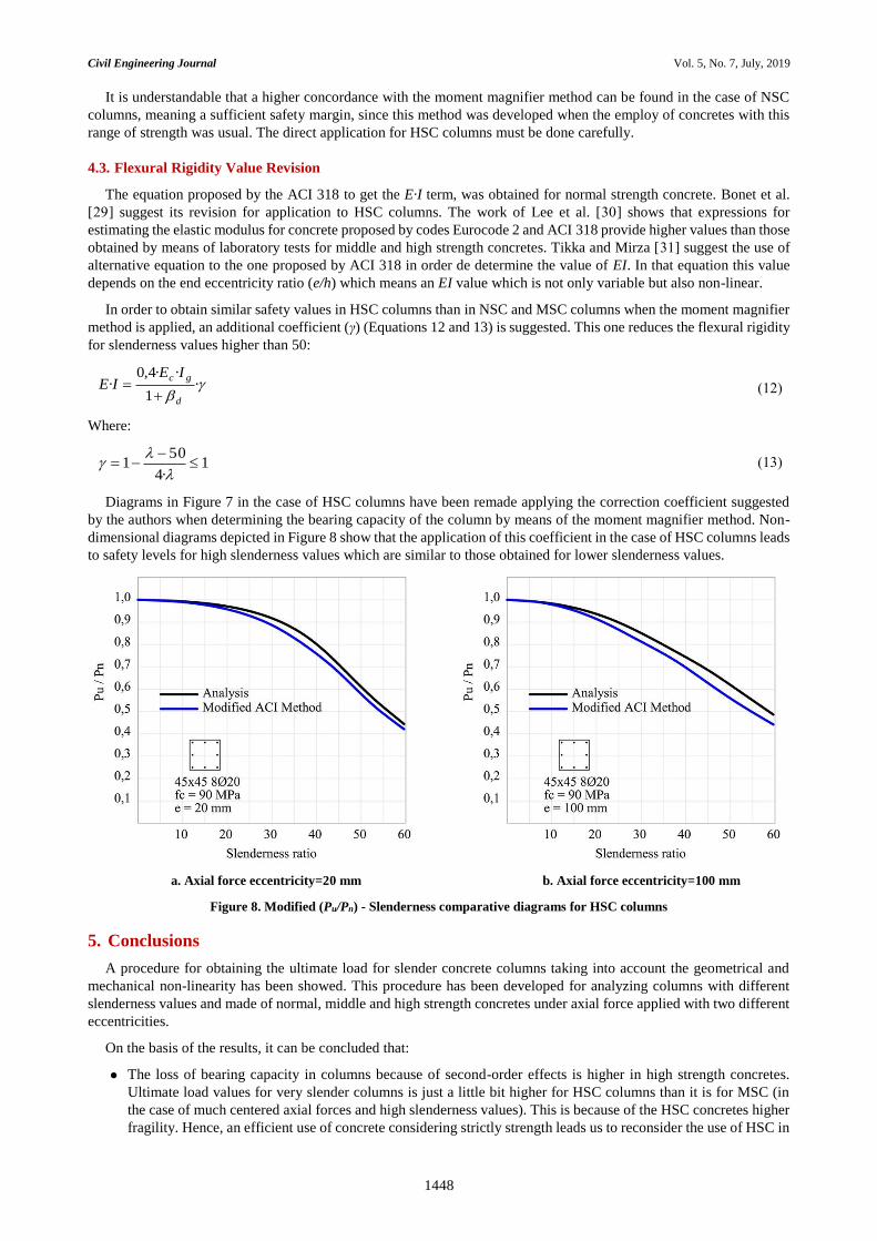
Diagrams in Figure 7 in the case of HSC columns have been remade applying the correction coefficient suggested
by the authors when determining the bearing capacity of the column by means of the moment magnifier method. Non-
dimensional diagrams depicted in Figure 8 show that the application of this coefficient in the case of HSC columns leads
to safety levels for high slenderness values which are similar to those obtained for lower slenderness values.
a. Axial force eccentricity=20 mm b. Axial force eccentricity=100 mm
Figure 8. Modified (Pu/Pn) - Slenderness comparative diagrams for HSC columns
5. Conclusions
A procedure for obtaining the ultimate load for slender concrete columns taking into account the geometrical and
mechanical non-linearity has been showed. This procedure has been developed for analyzing columns with different
slenderness values and made of normal, middle and high strength concretes under axial force applied with two different
eccentricities.
On the basis of the results, it can be concluded that:
The loss of bearing capacity in columns because of second-order effects is higher in high strength concretes.
Ultimate load values for very slender columns is just a little bit higher for HSC columns than it is for MSC (in
the case of much centered axial forces and high slenderness values). This is because of the HSC concretes higher
fragility. Hence, an efficient use of concrete considering strictly strength leads us to reconsider the use of HSC in
Civil Engineering Journal Vol. 5, No. 7, July, 2019
1449
very slender columns (λ>50). The work of Adinarayana and Ramudu provides a useful information about the
effect of using HSC columns on the atructural behaviour of buildings [32].
Increasing the axial force eccentricity produces a higher loss of the bar bearing capacity when compared with the
bearing capacity of the section. This phenomenon can be noticed for low or medium slenderness values in any
sort of concretes. However, this situation reverses in HSC columns with high slenderness values (Figure 6.c).
Thereupon, the use of high strength concrete for columns with high slenderness values is more effective when
the axial force comes along strong transversal thrusts such as those produced by wind or earthquakes. And it is
less effective in the case of strong gravity loads applied on the cross-section center of mass.
In the case of NSC and MSC columns, the moment magnifier method included in the ACI regulations has a very
good concordance with the laboratory tests and the analytical results exposed. However, it leads to excessively
tight or even unsafe values in the case of very slender HSC columns. This work has suggested the application of
a correction coefficient which reduces flexural rigidity and leads to more conservative values for this type of
columns
6. Nomenclature
fck Characteristic strength value for concrete;
fcm Compressive strength average value for concrete;
c1 Concrete strain due to maximum stress;
cu1 Ultimate concrete compressive strain;
fyk Characteristic strength value for steel;
u Ultimate steel compressive strain;
Ecm Secant modulus of elasticity for concrete;
λ Mechanical slenderness of the column;
Cm Coefficient which takes into consideration the axial force eccentricity applied;
ϕ Bearing capacity reduction coefficient;
Pcr Euler buckling load;
K Coefficient which takes into account the link conditions in both ends of the bar;
l0 Length of a bar with pin joints on both ends;
Ig Second moment of inertia of the concrete gross section;
i Bending radius for the concrete gross section;
βd Concrete creep factor;
Pn Ultimate load of the section;
Pu Ultimate load of the column;
PACI Ultimate load of the column in ACI method.
7. Funding
This work was supported by Universitat Politécnica de Valencia, Spain.
8. Conflicts of Interest
The authors declare no conflict of interest.
9. References
[1] Bresler, B. “Design criteria for reinforced concrete columns under axial load and biaxial bending.” ACI Journal Proceedings
(1960): 57, 481-90. doi:10.14359/8031.
[2] Hsu, C.T. “Analysis and design of square and rectangular columns by equation of failure surface.” ACI Structural Journal (1988):
vol. 85(2), 167-79. doi:10.14359/2730.
Civil Engineering Journal Vol. 5, No. 7, July, 2019
1450
[3] Mavichak, V., and Richard W. Furlong. “Strength and stiffness of reinforced concrete columns under biaxial bending.” No.
FHWA-TX-77-7-2F Final Rpt. Center for Highway Research, University of Texas at Austin, 1976.
[4] Al-Noury, Soliman I., and Wai F. Chen. "Finite segment method for biaxial loaded RC columns." Journal of the Structural Division
108, no. 4 (1982): 780-799.
[5 ]Kim, Jin-Keun, and Joo-Kyoung Yang. “Buckling Behaviour of Slender High-Strength Concrete Columns.” Engineering
Structures 17, no. 1 (January 1995): 39–51. doi:10.1016/0141-0296(95)91039-4.
[6] Lee, Tai-Kuang, Cheng-Cheng Chen, Ken Hwa, and Austin D. E. Pan. “Performance of Large Reinforced Concrete Columns
Under Axial Compression Loads.” Proceedings of the Institution of Civil Engineers - Structures and Buildings 167, no. 5 (May
2014): 300–311. doi:10.1680/stbu.12.00011.
[7] Zhu, Wei-Qing, Gang Meng, and Jin-Qing Jia. “Experimental Studies on Axial Load Performance of High-Strength Concrete
Short Columns.” Proceedings of the Institution of Civil Engineers - Structures and Buildings 167, no. 9 (September 2014): 509–
519. doi:10.1680/stbu.13.00027.
[8] Dundar, Cengiz, and Serkan Tokgoz. “Strength of Biaxially Loaded High Strength Reinforced Concrete Columns.” Structural
Engineering and Mechanics 44, no. 5 (December 10, 2012): 649–661. doi:10.12989/sem.2012.44.5.649.
[9] Hung, Chung-Chan, Fuo-Yao Hu, and Cheng-Hao Yen. “Behavior of Slender UHPC Columns under Eccentric Loading.”
Engineering Structures 174 (November 2018): 701–711. doi:10.1016/j.engstruct.2018.07.088.
[10] Barrera, A.C., J.L. Bonet, M.L. Romero, and P.F. Miguel. “Experimental Tests of Slender Reinforced Concrete Columns under
Combined Axial Load and Lateral Force.” Engineering Structures 33, no. 12 (December 2011): 3676–3689.
doi:10.1016/j.engstruct.2011.08.003.
[11] American Concrete Institute (ACI), “318-14: Building Code Requirements for Structural Concrete and Commentary” (November
6, 2014). doi:10.14359/51688187.
[12] Leite, L., J.L. Bonet, L. Pallarés, Pedro F. Miguel, and Miguel A. Fernández-Prada. “Experimental Research on High Strength
Concrete Slender Columns Subjected to Compression and Uniaxial Bending with Unequal Eccentricities at the Ends.”
Engineering Structures 48 (March 2013): 220–232. doi:10.1016/j.engstruct.2012.07.039.
[13] McGuire, W., Gallagher, R. and Ziemian, R. “Matrix structural analysis” (2000) John Wiley & Sons, Inc. New York, USA.
[14] Saber Agha, Ayad Zeki, and Mereen Hassan Fahmi Rashid. “Prediction of the Design Load for High Strength Concrete Columns.”
Journal of Civil & Environmental Engineering 06, no. 06 (2016): 1-9. doi:10.4172/2165-784x.1000260.
[15] Abdel-Karim, Mahmoud, Gamal T. Abdel-Rahman, Mohamed Said, and Ibrahim G. Shaaban. “Proposed Model for Strength
Analysis of HSC Eccentrically Loaded Slender Columns.” Magazine of Concrete Research 70, no. 7 (April 2018): 340–349.
doi:10.1680/jmacr.17.00137.
[16] Pires, Susana L., and Maria Cecilia A.T. Silva. “A Numerical Procedure for Reinforced Concrete Columns with a Focus on
Stability Analysis.” Computers and Concrete 14, no. 6 (December 25, 2014): 657–674. doi:10.12989/cac.2014.14.6.657.
[17] Eurocode 2: Design of Concrete Structures. Part 1-1: General Rules and Rules for Building (EN 1992-1-1:2010). (2010)
European Committee for Standardization, Brussels.
[18] Kwak, Hyo-Gyoung, and Jin-Kook Kim. “Nonlinear Behavior of Slender RC Columns.” Construction and Building Materials
20, no. 8 (October 2006): 527–537. doi:10.1016/j.conbuildmat.2005.01.036.
[19] Pallarés, L., J.L. Bonet, P.F. Miguel, and M.A. Fernández Prada. “Experimental Research on High Strength Concrete Slender
Columns Subjected to Compression and Biaxial Bending Forces.” Engineering Structures 30, no. 7 (July 2008): 1879–1894.
doi:10.1016/j.engstruct.2007.12.005.
[20] ANGLE Structural Analysis Software for Finite Elements. Research version. (2018) Department of Continuum Mechanics and
Theory of Structures. Universitat Politècnica de València, Spain.
[21] Wang, Gang Gary, and Cheng-Tzu Thomas Hsu. "Complete biaxial load-deformation behavior or RC columns." Journal of
Structural engineering 118, no. 9 (1992): 2590-2609. doi: 10.1061/(asce)0733-9445(1992)118:9(2590).
[22] Fenollosa, E., Adolfo Alonso-Durá, and V Llopis. “Method for Evaluating the Flexural Stiffness Bar of Reinforced Concrete
Structures.” Applied Mechanics and Materials 351–352 (August 2013): 67–74. doi:10.4028/www.scientific.net/amm.351-
352.67.
[23] Kwak, Hyo-Gyoung, and Jin-Kook Kim. “Ultimate Resisting Capacity of Slender RC Columns.” Computers & Structures 82,
no. 11–12 (May 2004): 901–915. doi:10.1016/j.compstruc.2004.02.019.
[24] Bonet, J.L., P.F. Miguel, M.A. Fernandez, and M.L. Romero. “Biaxial Bending Moment Magnifier Method.” Engineering
Structures 26, no. 13 (November 2004): 2007–2019. doi:10.1016/j.engstruct.2004.08.001.
Civil Engineering Journal Vol. 5, No. 7, July, 2019
1451
[25] Tikka, Timo K., and S. Ali Mirza. “Effective Flexural Stiffness of Slender Structural Concrete Columns.” Canadian Journal of
Civil Engineering 35, no. 4 (April 2008): 384–399. doi:10.1139/l07-113.
[26] Bedirhanoglu, Idris. “A Practical Neuro-Fuzzy Model for Estimating Modulus of Elasticity of Concrete.” Structural Engineering
and Mechanics 51, no. 2 (July 25, 2014): 249–265. doi:10.12989/sem.2014.51.2.249.
[27] Baqersad, Mohamadtaqi, Ehsan Amir Sayyafi, and Hamid Mortazavi Bak. "State of the art: mechanical properties of ultra-high
performance concrete." Civil Engineering Journal 3, no. 3 (2017): 190-198.
[28 ] Mendis, Priyan A. "Behavior of slender high-strength concrete columns." Structural Journal 97, no. 6 (2000): 895-901.
doi:10.14359/9635.
[29] Bonet, J.L., M.L. Romero, and P.F. Miguel. “Effective Flexural Stiffness of Slender Reinforced Concrete Columns under Axial
Forces and Biaxial Bending.” Engineering Structures 33, no. 3 (March 2011): 881–893. doi:10.1016/j.engstruct.2010.12.009.
[30] Lee, Byung Jae, Seong-Hoon Kee, Taekeun Oh, and Yun-Yong Kim. “Effect of Cylinder Size on the Modulus of Elasticity and
Compressive Strength of Concrete from Static and Dynamic Tests.” Advances in Materials Science and Engineering 2015 (2015):
1–12. doi:10.1155/2015/580638.
[31] Tikka, Timo K., and S. Ali Mirza. “Effective Length of Reinforced Concrete Columns in Braced Frames.” International Journal
of Concrete Structures and Materials 8, no. 2 (May 20, 2014): 99–116. doi:10.1007/s40069-014-0070-7.
[32] Adinarayana. P and Ramudu, K. “Effect of Using High Strength Concrete Columns on the Structural Behaviour of R.C Buildings.”
International Journal of Engineering Sciences & Research Technology (2017): 6(3), 467-475. doi: 10.5281/zenodo.438285.