Embed Size (px)
Citation preview
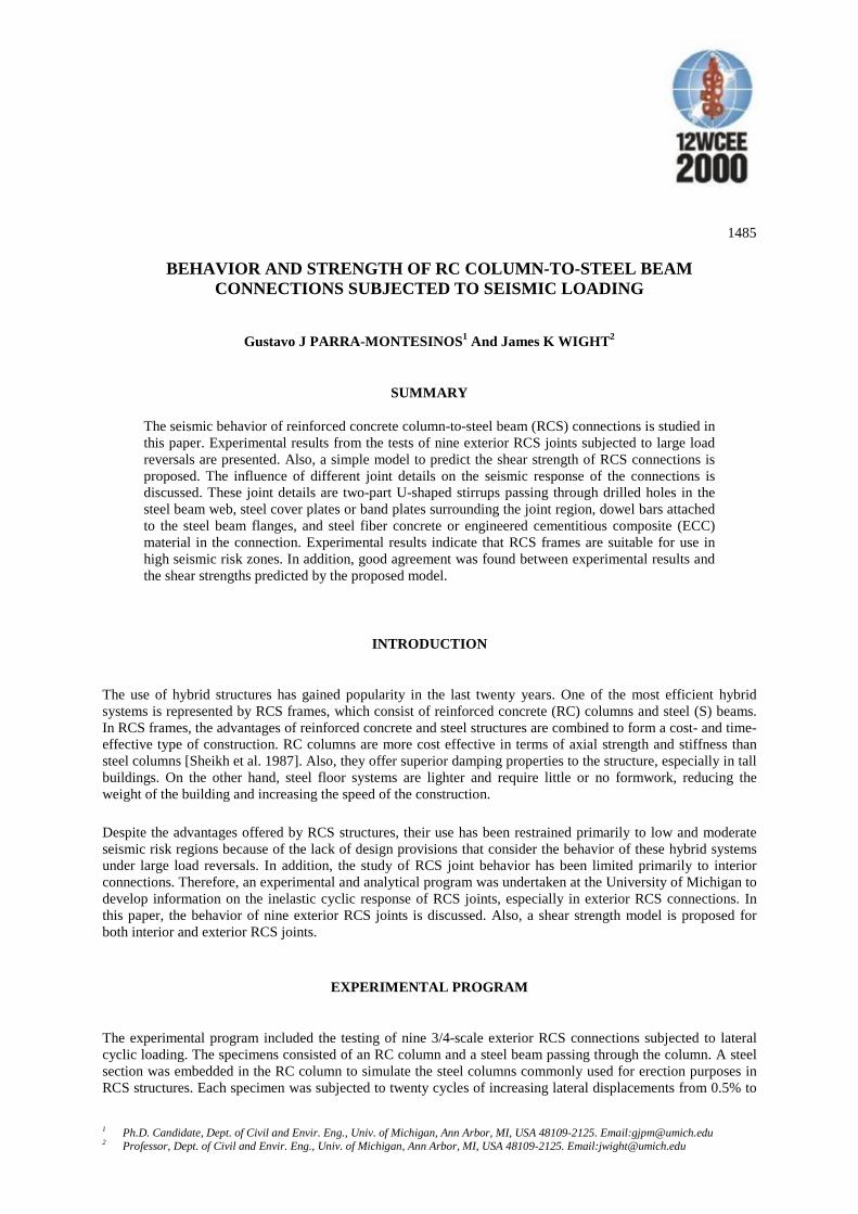
1485
1 Ph.D. Candidate, Dept. of Civil and Envir. Eng., Univ. of Michigan, Ann Arbor, MI, USA 48109-2125. Email:[email protected] Professor, Dept. of Civil and Envir. Eng., Univ. of Michigan, Ann Arbor, MI, USA 48109-2125. Email:[email protected]
BEHAVIOR AND STRENGTH OF RC COLUMN-TO-STEEL BEAMCONNECTIONS SUBJECTED TO SEISMIC LOADING
Gustavo J PARRA-MONTESINOS1 And James K WIGHT2
SUMMARY
The seismic behavior of reinforced concrete column-to-steel beam (RCS) connections is studied inthis paper. Experimental results from the tests of nine exterior RCS joints subjected to large loadreversals are presented. Also, a simple model to predict the shear strength of RCS connections isproposed. The influence of different joint details on the seismic response of the connections isdiscussed. These joint details are two-part U-shaped stirrups passing through drilled holes in thesteel beam web, steel cover plates or band plates surrounding the joint region, dowel bars attachedto the steel beam flanges, and steel fiber concrete or engineered cementitious composite (ECC)material in the connection. Experimental results indicate that RCS frames are suitable for use inhigh seismic risk zones. In addition, good agreement was found between experimental results andthe shear strengths predicted by the proposed model.
INTRODUCTION
The use of hybrid structures has gained popularity in the last twenty years. One of the most efficient hybridsystems is represented by RCS frames, which consist of reinforced concrete (RC) columns and steel (S) beams.In RCS frames, the advantages of reinforced concrete and steel structures are combined to form a cost- and time-effective type of construction. RC columns are more cost effective in terms of axial strength and stiffness thansteel columns [Sheikh et al. 1987]. Also, they offer superior damping properties to the structure, especially in tallbuildings. On the other hand, steel floor systems are lighter and require little or no formwork, reducing theweight of the building and increasing the speed of the construction.
Despite the advantages offered by RCS structures, their use has been restrained primarily to low and moderateseismic risk regions because of the lack of design provisions that consider the behavior of these hybrid systemsunder large load reversals. In addition, the study of RCS joint behavior has been limited primarily to interiorconnections. Therefore, an experimental and analytical program was undertaken at the University of Michigan todevelop information on the inelastic cyclic response of RCS joints, especially in exterior RCS connections. Inthis paper, the behavior of nine exterior RCS joints is discussed. Also, a shear strength model is proposed forboth interior and exterior RCS joints.
EXPERIMENTAL PROGRAM
The experimental program included the testing of nine 3/4-scale exterior RCS connections subjected to lateralcyclic loading. The specimens consisted of an RC column and a steel beam passing through the column. A steelsection was embedded in the RC column to simulate the steel columns commonly used for erection purposes inRCS structures. Each specimen was subjected to twenty cycles of increasing lateral displacements from 0.5% to
14852
5.0% story drift. Each cycle to a higher story drift level was performed twice to evaluate the stiffness retentioncapacity of the specimens during repeated cycles.
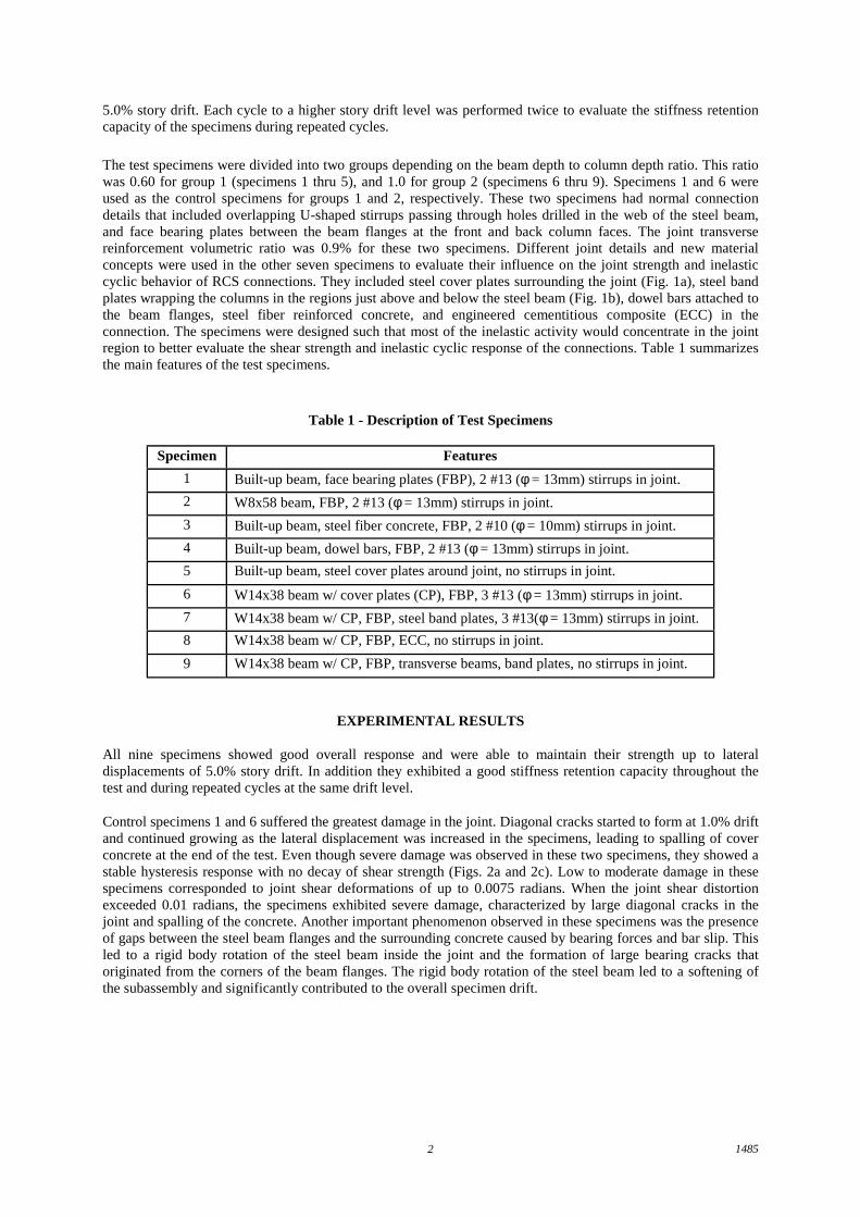
The test specimens were divided into two groups depending on the beam depth to column depth ratio. This ratiowas 0.60 for group 1 (specimens 1 thru 5), and 1.0 for group 2 (specimens 6 thru 9). Specimens 1 and 6 wereused as the control specimens for groups 1 and 2, respectively. These two specimens had normal connectiondetails that included overlapping U-shaped stirrups passing through holes drilled in the web of the steel beam,and face bearing plates between the beam flanges at the front and back column faces. The joint transversereinforcement volumetric ratio was 0.9% for these two specimens. Different joint details and new materialconcepts were used in the other seven specimens to evaluate their influence on the joint strength and inelasticcyclic behavior of RCS connections. They included steel cover plates surrounding the joint (Fig. 1a), steel bandplates wrapping the columns in the regions just above and below the steel beam (Fig. 1b), dowel bars attached tothe beam flanges, steel fiber reinforced concrete, and engineered cementitious composite (ECC) in theconnection. The specimens were designed such that most of the inelastic activity would concentrate in the jointregion to better evaluate the shear strength and inelastic cyclic response of the connections. Table 1 summarizesthe main features of the test specimens.
Table 1 - Description of Test Specimens
Specimen Features
1 Built-up beam, face bearing plates (FBP), 2 #13 (φ = 13mm) stirrups in joint.
2 W8x58 beam, FBP, 2 #13 (φ = 13mm) stirrups in joint.
3 Built-up beam, steel fiber concrete, FBP, 2 #10 (φ = 10mm) stirrups in joint.
4 Built-up beam, dowel bars, FBP, 2 #13 (φ = 13mm) stirrups in joint.
5 Built-up beam, steel cover plates around joint, no stirrups in joint.
6 W14x38 beam w/ cover plates (CP), FBP, 3 #13 (φ = 13mm) stirrups in joint.
7 W14x38 beam w/ CP, FBP, steel band plates, 3 #13(φ = 13mm) stirrups in joint.
8 W14x38 beam w/ CP, FBP, ECC, no stirrups in joint.
9 W14x38 beam w/ CP, FBP, transverse beams, band plates, no stirrups in joint.
EXPERIMENTAL RESULTS
All nine specimens showed good overall response and were able to maintain their strength up to lateraldisplacements of 5.0% story drift. In addition they exhibited a good stiffness retention capacity throughout thetest and during repeated cycles at the same drift level.
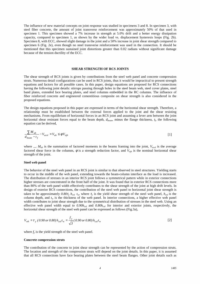
Control specimens 1 and 6 suffered the greatest damage in the joint. Diagonal cracks started to form at 1.0% driftand continued growing as the lateral displacement was increased in the specimens, leading to spalling of coverconcrete at the end of the test. Even though severe damage was observed in these two specimens, they showed astable hysteresis response with no decay of shear strength (Figs. 2a and 2c). Low to moderate damage in thesespecimens corresponded to joint shear deformations of up to 0.0075 radians. When the joint shear distortionexceeded 0.01 radians, the specimens exhibited severe damage, characterized by large diagonal cracks in thejoint and spalling of the concrete. Another important phenomenon observed in these specimens was the presenceof gaps between the steel beam flanges and the surrounding concrete caused by bearing forces and bar slip. Thisled to a rigid body rotation of the steel beam inside the joint and the formation of large bearing cracks thatoriginated from the corners of the beam flanges. The rigid body rotation of the steel beam led to a softening ofthe subassembly and significantly contributed to the overall specimen drift.

14853
b) Steel Band Plates in Specimen 7a) Steel Cover Plates in Specimen 5
Fig. 1 - Steel Cover Plates and Steel Band Plates in Test Specimens
The addition of special details and new materials to the joint region, such as dowel bars, steel cover plates andband plates, steel fiber reinforced concrete, and ECC material, led to significant improvements in the inelasticcyclic response of the joints compared to the control specimens. Dowel bars attached to the steel beam flangeseffectively distributed the stresses caused by bearing of the steel beam flanges on the surrounding concrete, asevidenced by a decrease in the damage observed in these regions of the columns. This led to a reduction in therigid body rotation of the steel beam inside the joint, and thus to an increase in the stiffness of the subassembly.
The influence of steel cover plates and band plates was studied in specimens 5, 7, and 9. Specimen 5 had steelcover plates surrounding the joint region over the beam depth. Because of the confinement provided by the coverplates, this specimen showed a 12% increase in shear strength at 5.0% drift compared to specimen 1 and had thebest stiffness retention capacity of all the specimens in group 1. Specimen 7, with steel band plates wrapping thecolumns in the regions just above and below the steel beam, exhibited a 50% increase in shear strength comparedto the control specimen 6 (Fig. 2d). Despite the increase in joint shear, the damage in the joint region wasmoderate (Fig. 1b) because the steel band plates effectively confined the concrete in the regions of the jointoutside the width of the beam flanges. Specimen 7 also showed the best stiffness retention capacity among thespecimens in group 2. Specimen 9 also had steel band plates. However, in this specimen no steel transversereinforcement was used in the joint because of the presence of transverse beams. This specimen showed onlymoderate damage up to 3.0% drift. As the lateral displacement was increased, diagonal cracks became larger,leading to a spalling of the concrete in the joint at the end of the test. Even though severe damage was observedin the joint at 5.0% story drift, specimen 9 showed a 25% increase in shear strength compared to specimen 6(Fig. 2f) and had a good stiffness retention capacity. This suggests that stirrups can be eliminated from theconnection if steel band plates are used in the joint.
-300
-200
-100
0
100
200
300
-6 -4 -2 0 2 4 6
La
tera
l L
oa
d (
KN
)
S tory Drift (% )
-300
-200
-100
0
100
200
300
-6 -4 -2 0 2 4 6
La
tera
l L
oa
d (
KN
)
Story Drift (% )
-300
-200
-100
0
100
200
300
-6 -4 -2 0 2 4 6
La
tera
l L
oa
d (
KN
)
S tory Drift (% )
c) Specimen 6
f) Specimen 9e) Specimen 8
-300
-200
-100
0
100
200
300
-6 -4 -2 0 2 4 6
La
tera
l L
oa
d (
KN
)
S tory Drift (% )
d) Specimen 7
-300
-200
-100
0
100
200
300
-6 -4 -2 0 2 4 6
La
tera
l L
oa
d (
KN
)
S tory Drift (% )
-300
-200
-100
0
100
200
300
-6 -4 -2 0 2 4 6
La
tera
l L
oa
d (
KN
)
Story D rift (% )
a) Specimen 1 b) Specimen 3
Fig. 2 - Load vs. Displacement Behavior
14854
The influence of new material concepts on joint response was studied in specimens 3 and 8. In specimen 3, withsteel fiber concrete, the amount of joint transverse reinforcement was approximately 50% of that used inspecimen 1. This specimen showed a 7% increase in strength at 5.0% drift and a better energy dissipationcapacity, compared to specimen 1, as shown by the wider load vs. displacement hysteresis loops (Fig. 2b).Specimen 8, with ECC, showed slight damage in the joint and a 50% increase in joint shear strength compared tospecimen 6 (Fig. 2e), even though no steel transverse reinforcement was used in the connection. It should bementioned that this specimen sustained joint distortions greater than 0.02 radians without significant damagebecause of the tension ductility of the ECC.
SHEAR STRENGTH OF RCS JOINTS
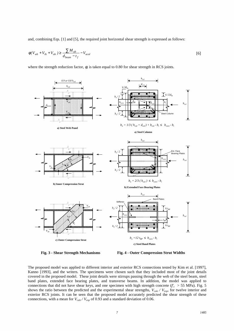
The shear strength of RCS joints is given by contributions from the steel web panel and concrete compressionstruts. Numerous detail configurations can be used in RCS joints, thus it would be impractical to present strengthequations and factors for all possible cases. In this paper, design equations are proposed for RCS connectionshaving the following joint details: stirrups passing through holes in the steel beam web, steel cover plates, steelband plates, extended face bearing plates, and steel columns embedded in the RC columns. The influence offiber reinforced concrete and engineered cementitious composite on shear strength is also considered in theproposed equations.
The design equations proposed in this paper are expressed in terms of the horizontal shear strength. Therefore, arelationship must be established between the external forces applied to the joint and the shear resistingmechanisms. From equilibrium of horizontal forces in an RCS joint and assuming a lever arm between the jointhorizontal shear resistant forces equal to the beam depth, dbeam, minus the flange thickness, tf, the followingequation can be derived,
njhuhucolfbeam
ub V VVtd
M φ≤=−−
∑[1]
where Mub is the summation of factored moments in the beams framing into the joint, Vucol is the averagefactored shear force in the columns, φ is a strength reduction factor, and Vnjh is the nominal horizontal shearstrength of the joint.
Steel web panel
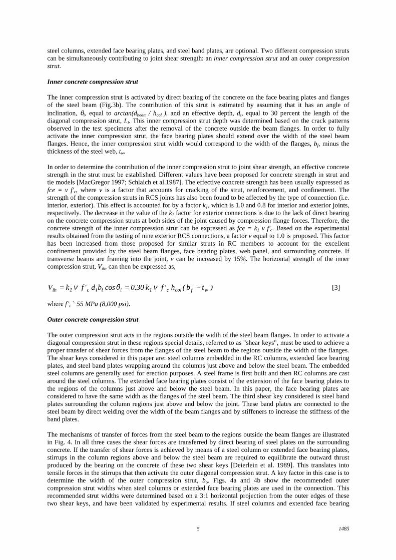
The behavior of the steel web panel in an RCS joint is similar to that observed in steel structures. Yielding startsto occur in the middle of the web panel, extending towards the beam-column interface as the load is increased.The distribution of stresses in an interior RCS joint follows a symmetrical pattern while in exterior connectionshigher stresses are concentrated in the front half of the joint. It was found that in exterior RCS connections morethan 80% of the web panel width effectively contributes to the shear strength of the joint at high drift levels. Indesign of exterior RCS connections, the contribution of the steel web panel to horizontal joint shear strength istaken to be approximately 0.80τy hcol tw, where τy is the yield shear strength of the steel web panel, hcol is thecolumn depth, and tw is the thickness of the web panel. In interior connections, a higher effective web panelwidth contributes to joint shear strength due to the symmetrical distribution of stresses in the steel web. Using aneffective web panel width equal to 0.90hcol and 0.80hcol for interior and exterior joints, respectively, thehorizontal shear strength of the steel web panel can be expressed as follows (Fig.3a),
wcoly
wcolywh th 0.80)or 90.0(3
fth 0.80)or 90.0( V ==τ [2]
where fy is the yield strength of the steel web panel.
Concrete compression struts
The contribution of the concrete to joint shear strength can be represented by the action of compression struts.The location and strength of the compression struts will depend on the joint details. In this paper, it is assumedthat all RCS connections have face bearing plates between the steel beam flanges. Other joint details such as
14855
steel columns, extended face bearing plates, and steel band plates, are optional. Two different compression strutscan be simultaneously contributing to joint shear strength: an inner compression strut and an outer compressionstrut.
Inner concrete compression strut
The inner compression strut is activated by direct bearing of the concrete on the face bearing plates and flangesof the steel beam (Fig.3b). The contribution of this strut is estimated by assuming that it has an angle ofinclination, θi, equal to arctan(dbeam / hcol ), and an effective depth, di, equal to 30 percent the length of thediagonal compression strut, Li. This inner compression strut depth was determined based on the crack patternsobserved in the test specimens after the removal of the concrete outside the beam flanges. In order to fullyactivate the inner compression strut, the face bearing plates should extend over the width of the steel beamflanges. Hence, the inner compression strut width would correspond to the width of the flanges, bf, minus thethickness of the steel web, tw.
In order to determine the contribution of the inner compression strut to joint shear strength, an effective concretestrength in the strut must be established. Different values have been proposed for concrete strength in strut andtie models [MacGregor 1997; Schlaich et al.1987]. The effective concrete strength has been usually expressed asfce = v f'c, where v is a factor that accounts for cracking of the strut, reinforcement, and confinement. Thestrength of the compression struts in RCS joints has also been found to be affected by the type of connection (i.e.interior, exterior). This effect is accounted for by a factor k1, which is 1.0 and 0.8 for interior and exterior joints,respectively. The decrease in the value of the k1 factor for exterior connections is due to the lack of direct bearingon the concrete compression struts at both sides of the joint caused by compression flange forces. Therefore, theconcrete strength of the inner compression strut can be expressed as fce = k1 v f'c. Based on the experimentalresults obtained from the testing of nine exterior RCS connections, a factor v equal to 1.0 is proposed. This factorhas been increased from those proposed for similar struts in RC members to account for the excellentconfinement provided by the steel beam flanges, face bearing plates, web panel, and surrounding concrete. Iftransverse beams are framing into the joint, v can be increased by 15%. The horizontal strength of the innercompression strut, Vih, can then be expressed as,
[3])tb(h'f k 30.0cosbd'f kV wfcolc1iiic1ih −== νθν
where f’c 55 MPa (8,000 psi).
Outer concrete compression strut
The outer compression strut acts in the regions outside the width of the steel beam flanges. In order to activate adiagonal compression strut in these regions special details, referred to as "shear keys", must be used to achieve aproper transfer of shear forces from the flanges of the steel beam to the regions outside the width of the flanges.The shear keys considered in this paper are: steel columns embedded in the RC columns, extended face bearingplates, and steel band plates wrapping around the columns just above and below the steel beam. The embeddedsteel columns are generally used for erection purposes. A steel frame is first built and then RC columns are castaround the steel columns. The extended face bearing plates consist of the extension of the face bearing plates tothe regions of the columns just above and below the steel beam. In this paper, the face bearing plates areconsidered to have the same width as the flanges of the steel beam. The third shear key considered is steel bandplates surrounding the column regions just above and below the joint. These band plates are connected to thesteel beam by direct welding over the width of the beam flanges and by stiffeners to increase the stiffness of theband plates.
The mechanisms of transfer of forces from the steel beam to the regions outside the beam flanges are illustratedin Fig. 4. In all three cases the shear forces are transferred by direct bearing of steel plates on the surroundingconcrete. If the transfer of shear forces is achieved by means of a steel column or extended face bearing plates,stirrups in the column regions above and below the steel beam are required to equilibrate the outward thrustproduced by the bearing on the concrete of these two shear keys [Deierlein et al. 1989]. This translates intotensile forces in the stirrups that then activate the outer diagonal compression strut. A key factor in this case is todetermine the width of the outer compression strut, bo. Figs. 4a and 4b show the recommended outercompression strut widths when steel columns or extended face bearing plates are used in the connection. Thisrecommended strut widths were determined based on a 3:1 horizontal projection from the outer edges of thesetwo shear keys, and have been validated by experimental results. If steel columns and extended face bearing
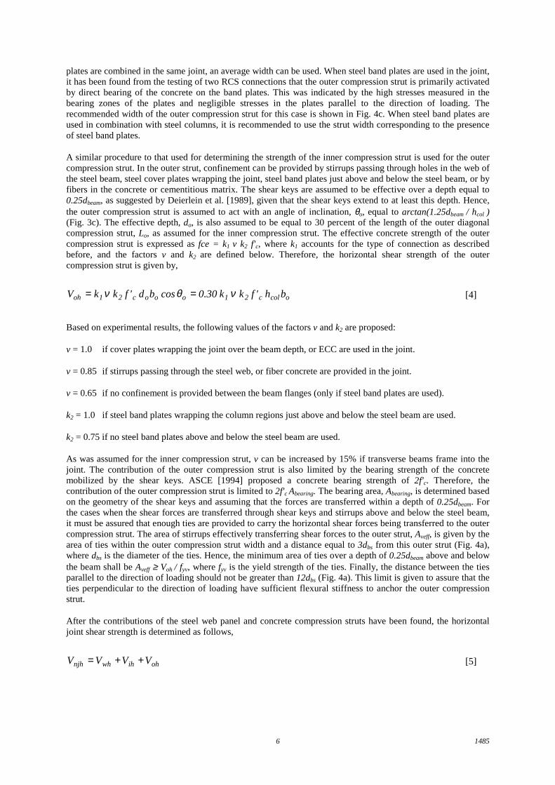
14856
plates are combined in the same joint, an average width can be used. When steel band plates are used in the joint,it has been found from the testing of two RCS connections that the outer compression strut is primarily activatedby direct bearing of the concrete on the band plates. This was indicated by the high stresses measured in thebearing zones of the plates and negligible stresses in the plates parallel to the direction of loading. Therecommended width of the outer compression strut for this case is shown in Fig. 4c. When steel band plates areused in combination with steel columns, it is recommended to use the strut width corresponding to the presenceof steel band plates.
A similar procedure to that used for determining the strength of the inner compression strut is used for the outercompression strut. In the outer strut, confinement can be provided by stirrups passing through holes in the web ofthe steel beam, steel cover plates wrapping the joint, steel band plates just above and below the steel beam, or byfibers in the concrete or cementitious matrix. The shear keys are assumed to be effective over a depth equal to0.25dbeam, as suggested by Deierlein et al. [1989], given that the shear keys extend to at least this depth. Hence,the outer compression strut is assumed to act with an angle of inclination, θo, equal to arctan(1.25dbeam / hcol )(Fig. 3c). The effective depth, do, is also assumed to be equal to 30 percent of the length of the outer diagonalcompression strut, Lo, as assumed for the inner compression strut. The effective concrete strength of the outercompression strut is expressed as fce = k1 v k2 f'c, where k1 accounts for the type of connection as describedbefore, and the factors v and k2 are defined below. Therefore, the horizontal shear strength of the outercompression strut is given by,
[4]ocolc21oooc2 1oh bh'fk k 30.0cosbd'fk kV νθν ==
Based on experimental results, the following values of the factors v and k2 are proposed:
v = 1.0 if cover plates wrapping the joint over the beam depth, or ECC are used in the joint.
v = 0.85 if stirrups passing through the steel web, or fiber concrete are provided in the joint.
v = 0.65 if no confinement is provided between the beam flanges (only if steel band plates are used).
k2 = 1.0 if steel band plates wrapping the column regions just above and below the steel beam are used.
k2 = 0.75 if no steel band plates above and below the steel beam are used.
As was assumed for the inner compression strut, v can be increased by 15% if transverse beams frame into thejoint. The contribution of the outer compression strut is also limited by the bearing strength of the concretemobilized by the shear keys. ASCE [1994] proposed a concrete bearing strength of 2f'c. Therefore, thecontribution of the outer compression strut is limited to 2f'c Abearing. The bearing area, Abearing, is determined basedon the geometry of the shear keys and assuming that the forces are transferred within a depth of 0.25dbeam. Forthe cases when the shear forces are transferred through shear keys and stirrups above and below the steel beam,it must be assured that enough ties are provided to carry the horizontal shear forces being transferred to the outercompression strut. The area of stirrups effectively transferring shear forces to the outer strut, Aveff, is given by thearea of ties within the outer compression strut width and a distance equal to 3dbs from this outer strut (Fig. 4a),where dbs is the diameter of the ties. Hence, the minimum area of ties over a depth of 0.25dbeam above and belowthe beam shall be Aveff ≥ Voh / fyv, where fyv is the yield strength of the ties. Finally, the distance between the tiesparallel to the direction of loading should not be greater than 12dbs (Fig. 4a). This limit is given to assure that theties perpendicular to the direction of loading have sufficient flexural stiffness to anchor the outer compressionstrut.
After the contributions of the steel web panel and concrete compression struts have been found, the horizontaljoint shear strength is determined as follows,
[5]ohihwhnjh VVVV ++=
14857
and, combining Eqs. [1] and [5], the required joint horizontal shear strength is expressed as follows:
[6]ucolfbeam
ubohihwh V
td
M)VVV( −
−≥++ ∑φ
where the strength reduction factor, φ, is taken equal to 0.80 for shear strength in RCS joints.
������������������������������������������������������������������������������������������������������������������������������������������������������������������������������������
�������������������������������������������������������������������
�������������������������������������������������������������������
��������������������
����������Vwh
Vwh
0.9 or 0.8 hcol
hcol
a) Steel Web Panel
dbeam
��������������������������������������������������������������������������������������������������������������������������������������
�������������������������������������������������������������������
��������������������
������������Vih
Vih
b) Inner Compression Strut
�������������������������������������������������������������������
��������������������������������������������������������������������������������������������������������������������������������������
����������������
������������
Voh
Voh
θo
c) Outer Compression Strut
�������������������������������������������������������������������������������������������������������������������������������������������������������������������������������������������������������������������������������������������������������������������������������������������������������������
L o
d o
��������������������������������������������������������������������������������������������������������������������������������������������������������
L i
d i
θi
����������������������������������������������������������������������������
����������������������������������������������������������������������������������
13
≤ 12dbs
dbs
bo / 2
bo / 2
hcol
dcol
bo = 1/3 ( hcol + dcol ) + bcol - bi ≤ bcore - bi
bibcore
a) Steel Column
���������������������������������������������������������������������������������������������������������������������������
���������������������������������������������������������������������������������������������������������������������������
bo / 2
bo / 2
���������������
���������
bo = 2/3 ( hcol ) ≤ bcore - bi
bcore
hcol
b) Extended Face Bearing Plates
Ext. FaceBearing Plates
bcol
����������
����������
������
������
��������������������������������������������������������������������������������
�������������������������������������������������������������������������������� 6 tBP
6 tBP
tBP
Band PlatesStiffener
bo =12 tBP ≤ bcore - bi
bcore
hcol
c) Steel Band Plates
bcol
bcol
Steel Column
≤ 3dbs
bcol
Fig. 3 - Shear Strength Mechanisms Fig. 4 - Outer Compression Strut Widths
bo / 2
bo / 2
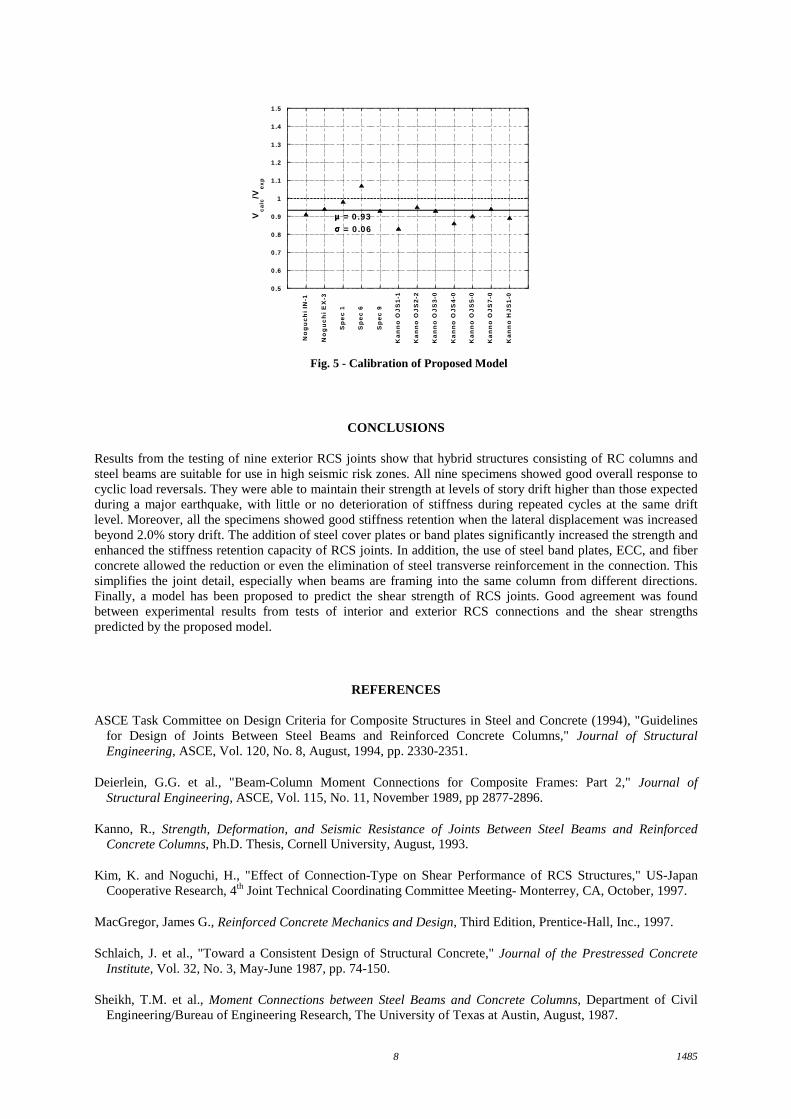
The proposed model was applied to different interior and exterior RCS connections tested by Kim et al. [1997],Kanno [1993], and the writers. The specimens were chosen such that they included most of the joint detailscovered in the proposed model. These joint details were stirrups passing through the web of the steel beam, steelband plates, extended face bearing plates, and transverse beams. In addition, the model was applied toconnections that did not have shear keys, and one specimen with high strength concrete (f'c > 55 MPa). Fig. 5shows the ratio between the predicted and the experimental shear strengths, Vcalc / Vexp, for twelve interior andexterior RCS joints. It can be seen that the proposed model accurately predicted the shear strength of theseconnections, with a mean for Vcalc / Vexp of 0.93 and a standard deviation of 0.06.
14858
0 .5
0 .6
0 .7
0 .8
0 .9
1
1 .1
1 .2
1 .3
1 .4
1 .5
No
gu
ch
i IN
-1
No
gu
ch
i E
X-3
Sp
ec
1
Sp
ec
6
Sp
ec
9
Ka
nn
o O
JS
1-1
Ka
nn
o O
JS
2-2
Ka
nn
o O
JS
3-0
Ka
nn
o O
JS
4-0
Ka
nn
o O
JS
5-0
Ka
nn
o O
JS
7-0
Ka
nn
o H
JS
1-0
Vc
alc
/Ve
xp
µµµµ = 0 .93σσσσ = 0 .06
Fig. 5 - Calibration of Proposed Model
CONCLUSIONS
Results from the testing of nine exterior RCS joints show that hybrid structures consisting of RC columns andsteel beams are suitable for use in high seismic risk zones. All nine specimens showed good overall response tocyclic load reversals. They were able to maintain their strength at levels of story drift higher than those expectedduring a major earthquake, with little or no deterioration of stiffness during repeated cycles at the same driftlevel. Moreover, all the specimens showed good stiffness retention when the lateral displacement was increasedbeyond 2.0% story drift. The addition of steel cover plates or band plates significantly increased the strength andenhanced the stiffness retention capacity of RCS joints. In addition, the use of steel band plates, ECC, and fiberconcrete allowed the reduction or even the elimination of steel transverse reinforcement in the connection. Thissimplifies the joint detail, especially when beams are framing into the same column from different directions.Finally, a model has been proposed to predict the shear strength of RCS joints. Good agreement was foundbetween experimental results from tests of interior and exterior RCS connections and the shear strengthspredicted by the proposed model.
REFERENCES
ASCE Task Committee on Design Criteria for Composite Structures in Steel and Concrete (1994), "Guidelinesfor Design of Joints Between Steel Beams and Reinforced Concrete Columns," Journal of StructuralEngineering, ASCE, Vol. 120, No. 8, August, 1994, pp. 2330-2351.
Deierlein, G.G. et al., "Beam-Column Moment Connections for Composite Frames: Part 2," Journal ofStructural Engineering, ASCE, Vol. 115, No. 11, November 1989, pp 2877-2896.
Kanno, R., Strength, Deformation, and Seismic Resistance of Joints Between Steel Beams and ReinforcedConcrete Columns, Ph.D. Thesis, Cornell University, August, 1993.
Kim, K. and Noguchi, H., "Effect of Connection-Type on Shear Performance of RCS Structures," US-JapanCooperative Research, 4th Joint Technical Coordinating Committee Meeting- Monterrey, CA, October, 1997.
MacGregor, James G., Reinforced Concrete Mechanics and Design, Third Edition, Prentice-Hall, Inc., 1997.
Schlaich, J. et al., "Toward a Consistent Design of Structural Concrete," Journal of the Prestressed ConcreteInstitute, Vol. 32, No. 3, May-June 1987, pp. 74-150.
Sheikh, T.M. et al., Moment Connections between Steel Beams and Concrete Columns, Department of CivilEngineering/Bureau of Engineering Research, The University of Texas at Austin, August, 1987.