Embed Size (px)
Citation preview

1
Slender Columns
2
Slender Columns When a column bends or deflects laterally an amount Δ, its axial load will cause an increased column moment equal to PΔ. This moment will be superimposed onto any moments already in the column. Should this PΔ moment be of such magnitude as to reduce the axial load capacity of the column significantly, the column will be referred to as a slender column.
Section 10.10.1 of the Code states that the design of a compression member should, desirably, be based on a theoretical analysis of the structure that takes into account the effects of axial loads, moments, deflections, duration of loads, varying member sizes, end conditions, and so on. If such a theoretical procedure is not used, the Code (10.10.2) provides an approximate method for determining slenderness effects. This method, which is based on the factors just mentioned for an “exact” analysis, results in a moment magnifier δ, which is to be multiplied by the larger moment at the end of the column, and that value is used in design. If bending occurs about both axes, δ is to be computed separately for each direction and the values obtained multiplied by the respective moment values.
3
NONSWAY AND SWAY FRAMES For this discussion it is necessary to distinguish between frames without side sway and those with side sway. In the ACI Code these are referred to respectively as nonsway frames and sway frames.
The columns in nonsway frames must be designed according to Section 10.12 of the Code, while the columns of sway frames must be designed according to Section 10.13. As a result, it is first necessary to decide whether we have a nonsway frame or a sway frame. It must be realized that we rarely find a frame that is completely braced against swaying or one that is completely unbraced against swaying. Therefore, it is a delicate decision.
4
NONSWAY AND SWAY FRAMES The question may possibly be resolved by examining the lateral
stiffness of the bracing elements for the story in question. You may
observe that a particular column is located in a story where there is such
substantial lateral stiffness provided by bracing members, shear walls,
shear trusses, and so on that any lateral deflections occurring will be too
small to affect the strength of the column appreciably. You should realize
while examining a particular structure that there may be some nonsway
stories and some sway stories.
If we cannot tell by inspection whether we have a nonsway frame
or a sway frame, the Code provides two ways of making a decision. First, in
ACI Section 10.11.4.1, a story in a frame is said to be a nonsway one if the
increase in column end moments due to second-order effects is 5% or less
of the first-order end moments.
5
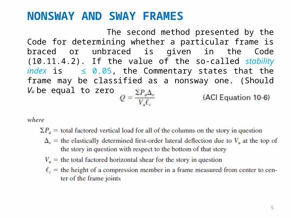
NONSWAY AND SWAY FRAMES The second method presented by the Code for determining whether a particular frame is braced or unbraced is given in the Code (10.11.4.2). If the value of the so-called stability index is ≤ 0.05, the Commentary states that the frame may be classified as a nonsway one. (Should Vu be equal to zero, this method will not apply.)
6
NONSWAY AND SWAY FRAMES
Despite these suggestions from the ACI, the individual designer is
going to have to make decision as to what is adequate bracing and what is
not, depending on the presence of structural walls and other bracing
items. For the average size reinforced concrete building, load eccentricities
and slenderness values will be small and frames will be considered to be
braced. Certainly, however, it is wise in questionable cases to err on the
side of the unbraced.
7
SLENDERNESS EFFECTS
The slenderness of columns is based on their geometry and on
their lateral bracing. As their slenderness increases, their bending stresses
increase, and thus buckling may occur. Reinforced concrete columns
generally have small slenderness ratios. As a result, they can usually be
designed as short columns without strength reductions because of
slenderness. If slenderness effects are considered small, then columns can
be considered “short” and can be designed according to Chapter 10.
However, if they are “slender,” the moment for which the column must be
designed is increased or magnified. Once the moment is magnified, the
column is then designed according to Chapter 10 using the increased
moment.
8
SLENDERNESS EFFECTSSeveral items involved in the calculation of slenderness ratios are
discussed. These include unsupported column lengths, effective length
factors, radii of gyration, and the ACI Code requirements. The ACI Code
(10.10.2.1) limits second-order effects to not more than 40% of first-order
effects.
Unsupported Lengths
The length used for calculating the slenderness ratio of a column,
lu, is its unsupported length. This length is considered to be equal to the
clear distance between slabs, beams, or other members that provide
lateral support to the column. If haunches or capitals (see Figure 16.1) are
present, the clear distance is measured from the bottoms of the capitals or
haunches.
9
SLENDERNESS EFFECTS
To calculate the slenderness ratio of a particular column, it is
necessary to estimate its effective length. This is the distance between
points of zero moment in the column. For this initial discussion it is
assumed that no sidesway or joint translation is possible. Sidesway or joint
translation means that one or both ends of a column can move laterally
with respect to each other.
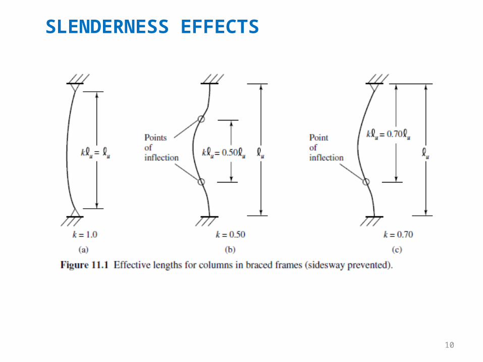
If there were such a thing as a perfectly pinned end column, its
effective length would be its supported length, as shown in Figure 11.1(a).
The effective length factor k is the number that must be multiplied by the
column’s unsupported length to obtain its effective length. For a perfectly
pinned end column, k = 1.0.
Effective Length Factors
10
SLENDERNESS EFFECTS
11
SLENDERNESS EFFECTS
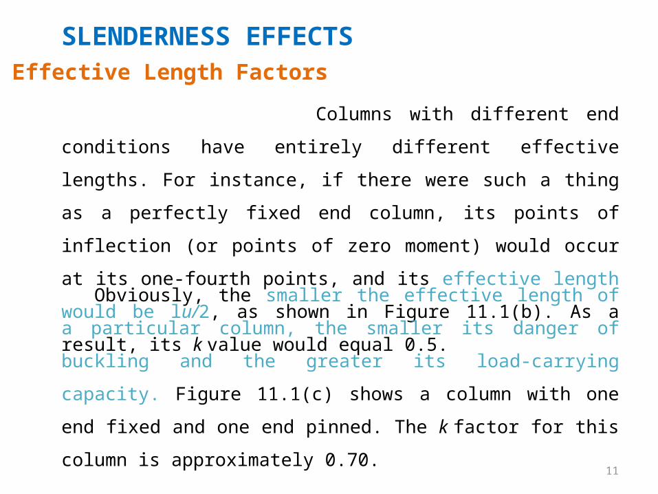
Columns with different end conditions have entirely different
effective lengths. For instance, if there were such a thing as a perfectly
fixed end column, its points of inflection (or points of zero moment) would
occur at its one-fourth points, and its effective length would be lu/2, as
shown in Figure 11.1(b). As a result, its k value would equal 0.5.
Obviously, the smaller the effective length of a particular column,
the smaller its danger of buckling and the greater its load-carrying
capacity. Figure 11.1(c) shows a column with one end fixed and one end
pinned. The k factor for this column is approximately 0.70.
Effective Length Factors
12
SLENDERNESS EFFECTS
The concept of effective lengths is simply a mathematical method
of taking a column—whatever its end and bracing conditions—and
replacing it with an equivalent pinned end-braced column. A complex
buckling analysis could be made for a frame to determine the critical stress
in a particular column. The k factor is determined by finding the pinned
end column with an equivalent length that provides the same critical
stress. The k factor procedure is a method of making simple solutions for
complicated frame-buckling problems.
Effective Length Factors
Reinforced concrete columns serve as parts of frames, and these
frames are sometimes braced and sometimes unbraced. A braced frame is
one for which sidesway or joint translation is prevented by means of
bracing, shear walls, or lateral support from adjoining structures.
13
SLENDERNESS EFFECTS
An unbraced frame does not have any of these types of bracing
supplied and must depend on the stiffness of its own members to prevent
lateral buckling. For braced frames, k values can never be greater than 1.0,
but for unbraced frames, the k values will always be greater than 1.0
because of sidesway.
Effective Length Factors
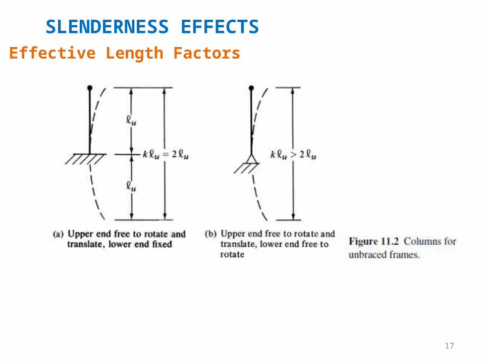
An example of an unbraced column is shown in Figure 11.2(a). The
base of this particular column is assumed to be fixed, whereas its upper
end is assumed to be completely free to both rotate and translate. The
elastic curve of such a column will take the shape of the elastic curve of a
pinned-end column of twice its length. Its effective length will therefore
equal 2lu, as shown in the figure. In Figure 11.2(b), another unbraced
column case is illustrated.
14
SLENDERNESS EFFECTS
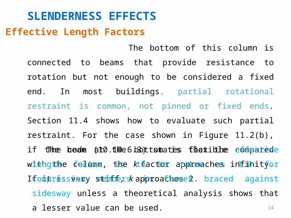
The bottom of this column is connected to beams that provide
resistance to rotation but not enough to be considered a fixed end. In most
buildings, partial rotational restraint is common, not pinned or fixed ends.
Section 11.4 shows how to evaluate such partial restraint. For the case
shown in Figure 11.2(b), if the beam at the bottom is flexible compared
with the column, the k factor approaches infinity. If it is very stiff, k
approaches 2.
Effective Length Factors
The code (10.10.6.3) states that the effective length factor is to be
taken as 1.0 for compression members in frames braced against sidesway
unless a theoretical analysis shows that a lesser value can be used.
15
SLENDERNESS EFFECTSEffective Length Factors
Should the member be in a frame not braced against sidesway,
the value of k will be larger than 1.0 and must be determined with proper
consideration given to the effects of cracking and reinforcing on the
column stiffness. ACI-ASCE Committee 441 suggests that it is not realistic
to assume that k will be less than 1.2 for such columns; therefore, it seems
logical to make preliminary designs with k equal to or larger than that
value.

16
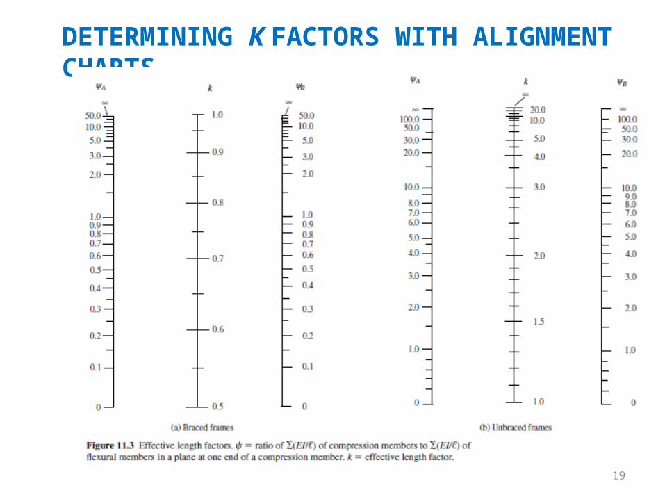
DETERMINING K FACTORS WITH ALIGNMENT CHARTSThe preliminary procedure used for estimating effective lengths
involves the use of the alignment charts shown in Figure 11.3.1,2. The chart of part (a) of the figure is applicable to braced frames, whereas the one of part (b) is applicable to unbraced frames.
To use the alignment charts for a particular column, ψ factors are computed at each end of the column. The ψ factor at one end of the column equals the sum of the stiffness [Σ(EI/l)] of the columns meeting at that joint, including the column in question, divided by the sum of all the stiffnesses of the beams meeting at the joint. Should one end of the column be pinned, ψ is theoretically equal to ∞, and if fixed, ψ = 0. Since a perfectly fixed end is practically impossible to have, ψ is usually taken as 1.0 instead of 0 for assumed fixed ends. When column ends are supported by, but not rigidly connected to a footing, is theoretically infinity, but usually is taken as about 10 for practical design.
17
SLENDERNESS EFFECTSEffective Length Factors
18
DETERMINING K FACTORS WITH ALIGNMENT CHARTS
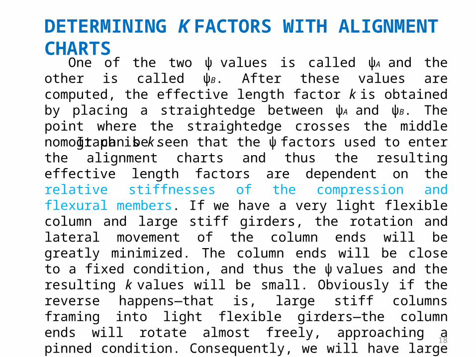
One of the two ψ values is called ψA and the other is called ψB. After these values are computed, the effective length factor k is obtained by placing a straightedge between ψA and ψB. The point where the straightedge crosses the middle nomograph is k.
It can be seen that the ψ factors used to enter the alignment charts and thus the resulting effective length factors are dependent on the relative stiffnesses of the compression and flexural members. If we have a very light flexible column and large stiff girders, the rotation and lateral movement of the column ends will be greatly minimized. The column ends will be close to a fixed condition, and thus the ψ values and the resulting k values will be small. Obviously if the reverse happens—that is, large stiff columns framing into light flexible girders—the column ends will rotate almost freely, approaching a pinned condition. Consequently, we will have large ψ and k values.
19
DETERMINING K FACTORS WITH ALIGNMENT CHARTS
20
DETERMINING K FACTORS WITH ALIGNMENT CHARTS
To calculate the ψ values it is necessary to use realistic moments of inertia. Usually, the girders will be appreciably cracked on their tensile sides, whereas the columns will probably have only a few cracks. If the I values for the girders are underestimated a little, the column k factors will be a little large and thus on the safe side.
Several approximate rules are in use for estimating beam and column rigidities. One common practice of the past for slenderness ratios of up to about 60 or 70 was to use gross moments of inertia for the columns and 50% of the gross moments of inertia for the beams.
In ACI Section 10.11.1, it is stated that for determining ψ values for use in evaluating k factors, the rigidity of the beams may be calculated on the basis of 0.35Ig to account for cracking and reinforcement, while 0.70Ig may be used for compression members. This practice is followed for the examples in this chapter. Other values for the estimated rigidity of walls and flat plates are provided in the same section.
21
DETERMINING K FACTORS WITH EQUATIONS
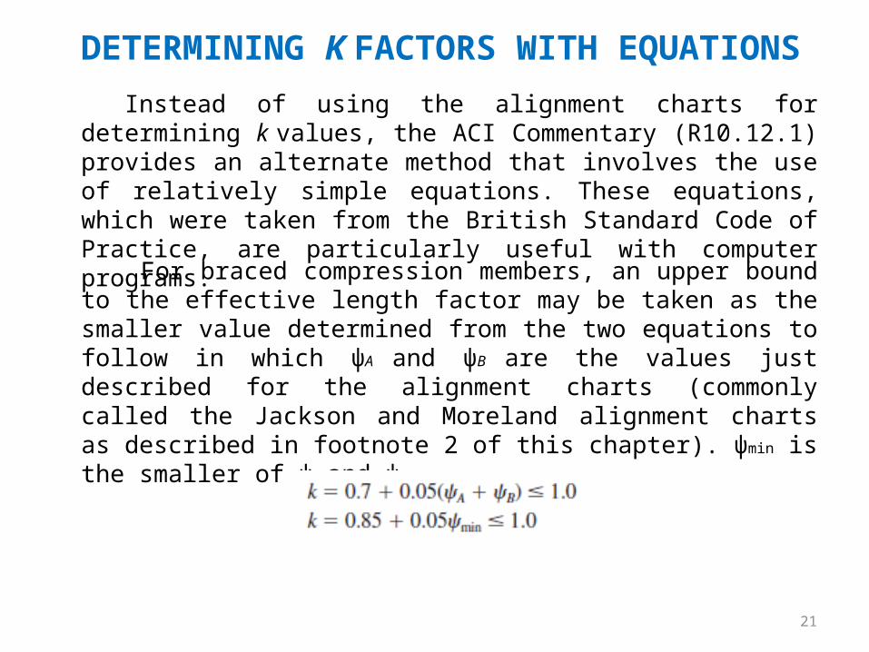
Instead of using the alignment charts for determining k values, the ACI Commentary (R10.12.1) provides an alternate method that involves the use of relatively simple equations. These equations, which were taken from the British Standard Code of Practice, are particularly useful with computer programs.
For braced compression members, an upper bound to the effective length factor may be taken as the smaller value determined from the two equations to follow in which ψA and ψB are the values just described for the alignment charts (commonly called the Jackson and Moreland alignment charts as described in footnote 2 of this chapter). ψmin is the smaller of ψA and ψB.
DETERMINING K FACTORS WITH EQUATIONS
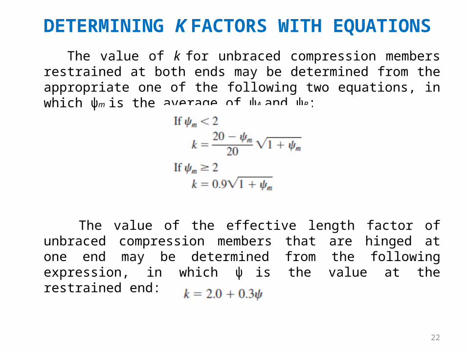
The value of k for unbraced compression members restrained at both ends may be determined from the appropriate one of the following two equations, in which ψm is the average of ψA and ψB:
The value of the effective length factor of unbraced compression members that are hinged at one end may be determined from the following expression, in which ψ is the value at the restrained end:
22
23
FIRST-ORDER ANALYSES USING SPECIAL MEMBER PROPERTIES
After this section, the remainder of the lecture is devoted to an approximate design procedure wherein the effect of slenderness is accounted for by computing moment magnifiers which are multiplied by the column moments. A magnifier for a particular column is a function of its factored axial load Pu and its critical buckling load Pc.
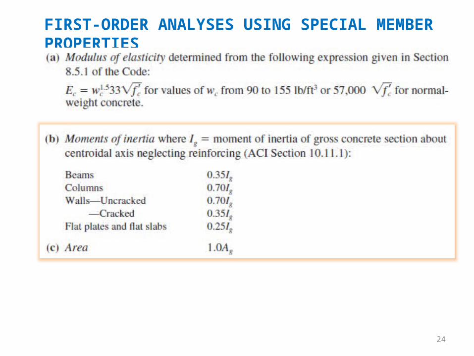
Before moment magnifiers can be computed for a particular structure, it is necessary to make a first-order analysis of the structure. The member section properties used for such an analysis should take into account the influence of axial loads, the presence of cracked regions in the members, and the effect of the duration of the loads. Instead of making such an analysis, ACI Code 10.11.1 permits use of the following properties for the members of the structure. These properties may be used for both nonsway and sway frames.
24
FIRST-ORDER ANALYSES USING SPECIAL MEMBER PROPERTIES
25
FIRST-ORDER ANALYSES USING SPECIAL MEMBER PROPERTIESThere is a major difference in the behavior of columns in nonsway
or braced frames and those in sway or unbraced frames. In effect, each column in a braced frame acts by itself. In other words, its individual strength can be determined and compared to its computed factored loads and moments. In an unbraced or sway frame, a column will probably not buckle individually but will probably buckle simultaneously with all of the other columns on the same level. As a result, it is necessary in a sway frame to consider the buckling strength of all the columns on the level in question as a unit.
For a compression member in a nonsway frame, the effective slenderness ratio klu /r is used to determine whether the member is short or slender. For this calculation, lu is the unbraced length of the member. The effective length factor k can be taken as 1.0 unless an analysis provides a lesser value. The radius of gyration r is equal to 0.25 times the diameter of a round column and 0.289 times the dimension of a rectangular column in the direction that stability is being considered. The ACI Code (10.11.2) permits the approximate value of 0.30 to be used in place of 0.289, and this is done herein. For other sections the value of r will have to be computed from the properties of the gross sections.
26
FIRST-ORDER ANALYSES USING SPECIAL MEMBER PROPERTIES
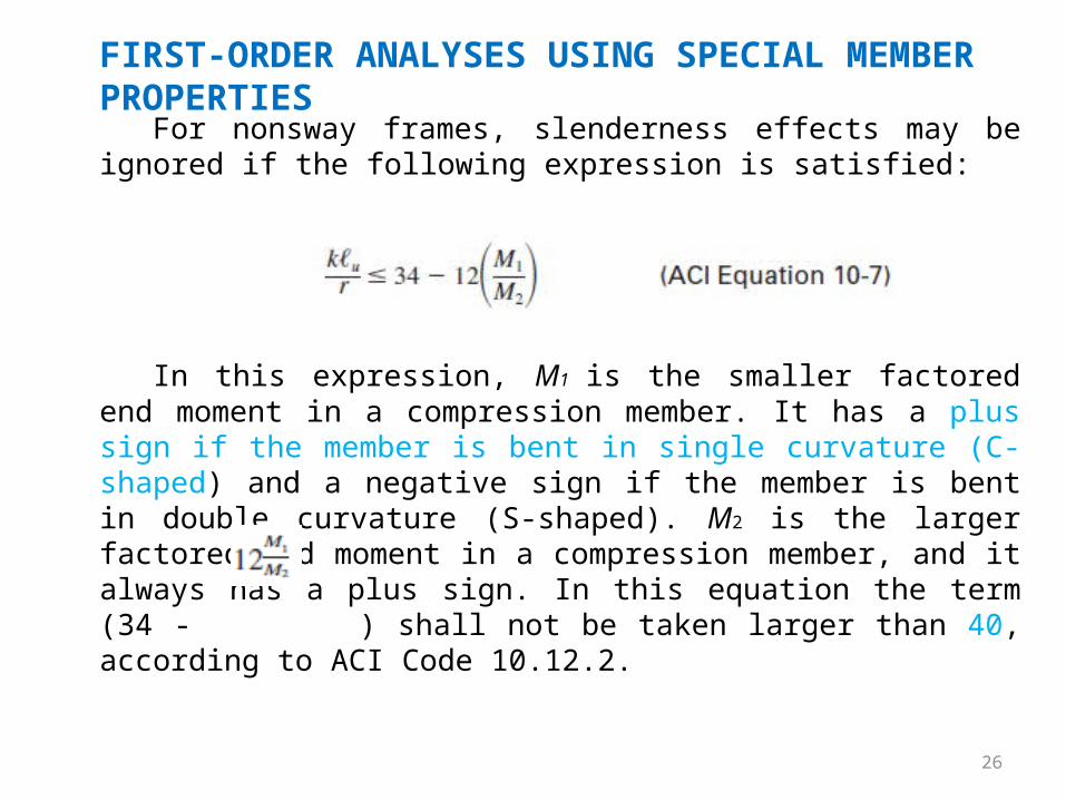
For nonsway frames, slenderness effects may be ignored if the following expression is satisfied:
In this expression, M1 is the smaller factored end moment in a compression member. It has a plus sign if the member is bent in single curvature (C-shaped) and a negative sign if the member is bent in double curvature (S-shaped). M2 is the larger factored end moment in a compression member, and it always has a plus sign. In this equation the term (34 - ) shall not be taken larger than 40, according to ACI Code 10.12.2.

27
FIRST-ORDER ANALYSES USING SPECIAL MEMBER PROPERTIES
Should klu/r for a particular column be larger than the applicable ratio, we will have a slender column. For such a column the effect of slenderness must be considered. This may be done by using approximate methods or by using a theoretical second-order analysis that takes into account the effect of deflections. If klu/r > 100, a theoretical second order analysis must be made (Code 10.11.5).
A second-order analysis is one that takes into account the effect of deflections and also makes use of a reduced tangent modulus. The equations necessary for designing a column in this range are extremely complicated, and, practically, it is necessary to use column design charts or computer programs. Fortunately, most reinforced concrete columns have slenderness ratios less than 100.
28
FIRST-ORDER ANALYSES USING SPECIAL MEMBER PROPERTIES
The design of slender columns is appreciably more complicated than the design of short columns. As a result, it may be wise to give some consideration to the use of certain minimum dimensions so that none of the columns will be slender. In this way they can be almost completely avoided in the average-size building.
If k is assumed equal to 1.0, slenderness can usually be neglected in braced frame columns if lu/h is kept to 10 or less on the first floor and 14 or less for the floors above the first one. To determine these values it was assumed that little moment resistance was provided at the footing–column connection and the first-floor columns were assumed to be bent in single curvature. Should the footing–column connection be designed to have appreciable moment resistance, the maximum lu/h value given above as 10 should be raised to about 14 or equal to the value used for the upper floors.
Avoiding Slender Columns
29
FIRST-ORDER ANALYSES USING SPECIAL MEMBER PROPERTIES
Should we have an unbraced frame and assume k = 1.2, it is probably necessary to keep lu/h to 6 or less. So for a 10-ft clear floor height it is necessary to use a minimum h of about 10 ft/6 = 1.67 ft = 20 in. in the direction of bending to avoid slender columns.
Example 11.1 illustrates the selection of the k factor and the determination of the slenderness ratio for a column in an unbraced frame. For calculating I/L values let us use 0.70 times the gross moments of inertia for the columns, 0.35 times the gross moments of inertia for the girders, and the full lengths of members center to center of supports.
Avoiding Slender Columns
30
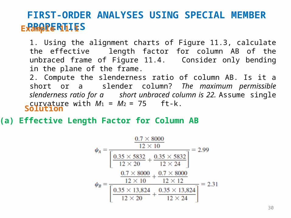
FIRST-ORDER ANALYSES USING SPECIAL MEMBER PROPERTIESExample 11.1
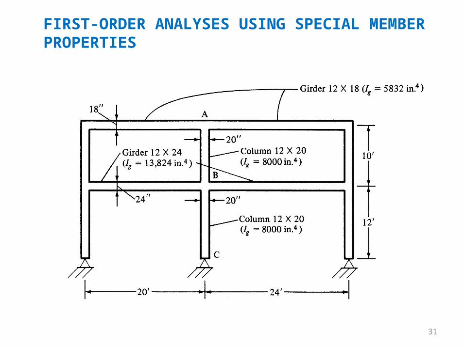
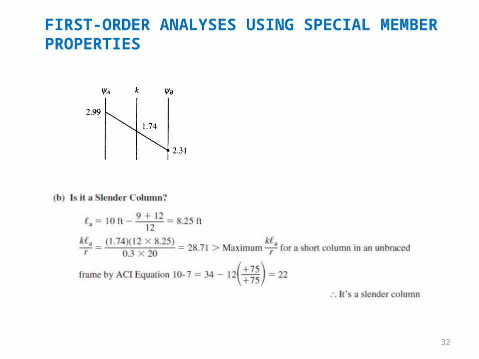
1. Using the alignment charts of Figure 11.3, calculate the effective length factor for column AB of the unbraced frame of Figure 11.4. Consider only bending in the plane of the frame.2. Compute the slenderness ratio of column AB. Is it a short or a slender column? The maximum permissible slenderness ratio for a short unbraced column is 22. Assume single curvature with M1 = M2 = 75 ft-k.
Solution(a) Effective Length Factor for Column AB
31
FIRST-ORDER ANALYSES USING SPECIAL MEMBER PROPERTIES
32
FIRST-ORDER ANALYSES USING SPECIAL MEMBER PROPERTIES
33
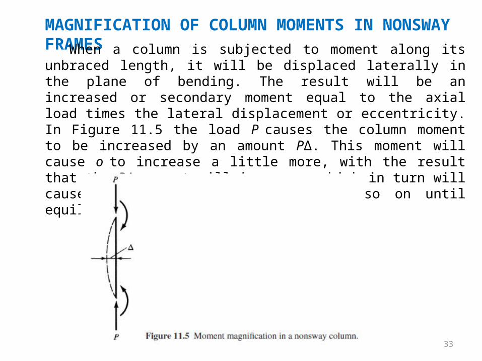
MAGNIFICATION OF COLUMN MOMENTS IN NONSWAY FRAMESWhen a column is subjected to moment along its unbraced length,
it will be displaced laterally in the plane of bending. The result will be an increased or secondary moment equal to the axial load times the lateral displacement or eccentricity. In Figure 11.5 the load P causes the column moment to be increased by an amount PΔ. This moment will cause o to increase a little more, with the result that the PΔ moment will increase, which in turn will cause a further increase in d and so on until equilibrium is reached.
34
MAGNIFICATION OF COLUMN MOMENTS IN NONSWAY FRAMESWe could take the column moments, compute the lateral deflection,
increase the moment by PΔ, recalculate the lateral deflection and the increased moment, and so on. Although about two cycles would be sufficient, this would still be a tedious and impractical procedure.
It can be shown that the increased moment can be estimated very well by multiplying the primary moment by 1/(1 - P/Pc), where P is the axial load and Pc is the Euler buckling load π²EI/(klu)².
In Example 11.2 this expression is used to estimate the magnified moment in a laterally loaded column. It will be noted that in this problem the primary moment of 75 ft-k is estimated to increase by 7.4 ft-k. If we computed the deflection due to the lateral load, we would get 0.445 in. For this value PΔ = (150)(0.445) = 66.75 in.-k = 5.6 ft-k. This moment causes more deflection, which causes more moment, and so on.
35
MAGNIFICATION OF COLUMN MOMENTS IN NONSWAY FRAMESExample 11.2
Solution
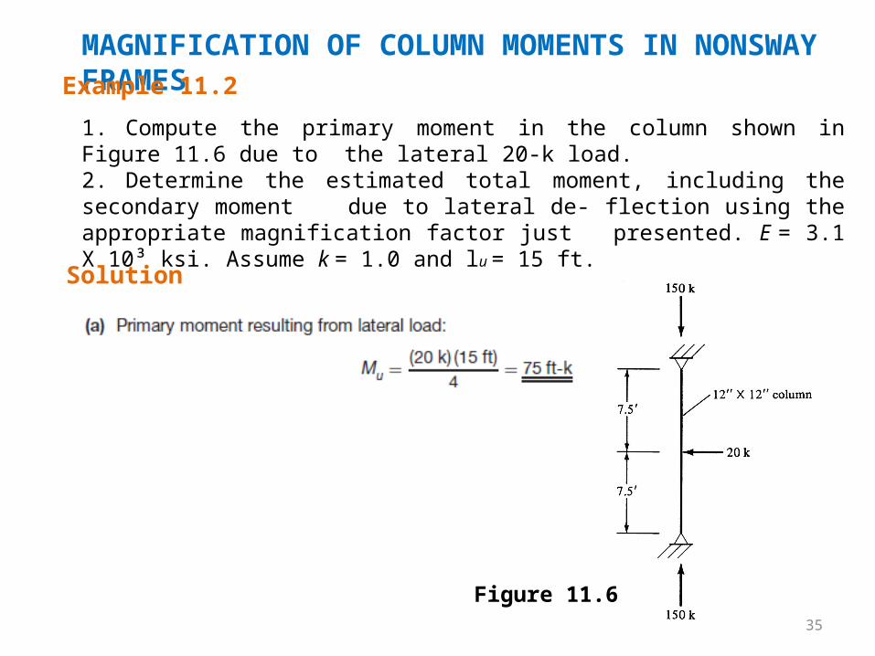
1. Compute the primary moment in the column shown in Figure 11.6 due to the lateral 20-k load.
2. Determine the estimated total moment, including the secondary moment due to lateral de- flection using the appropriate magnification factor just presented. E = 3.1 X 10³ ksi. Assume k = 1.0 and lu = 15 ft.
Figure 11.6
36
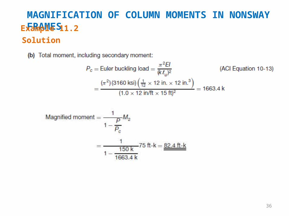
MAGNIFICATION OF COLUMN MOMENTS IN NONSWAY FRAMESExample 11.2Solution
37
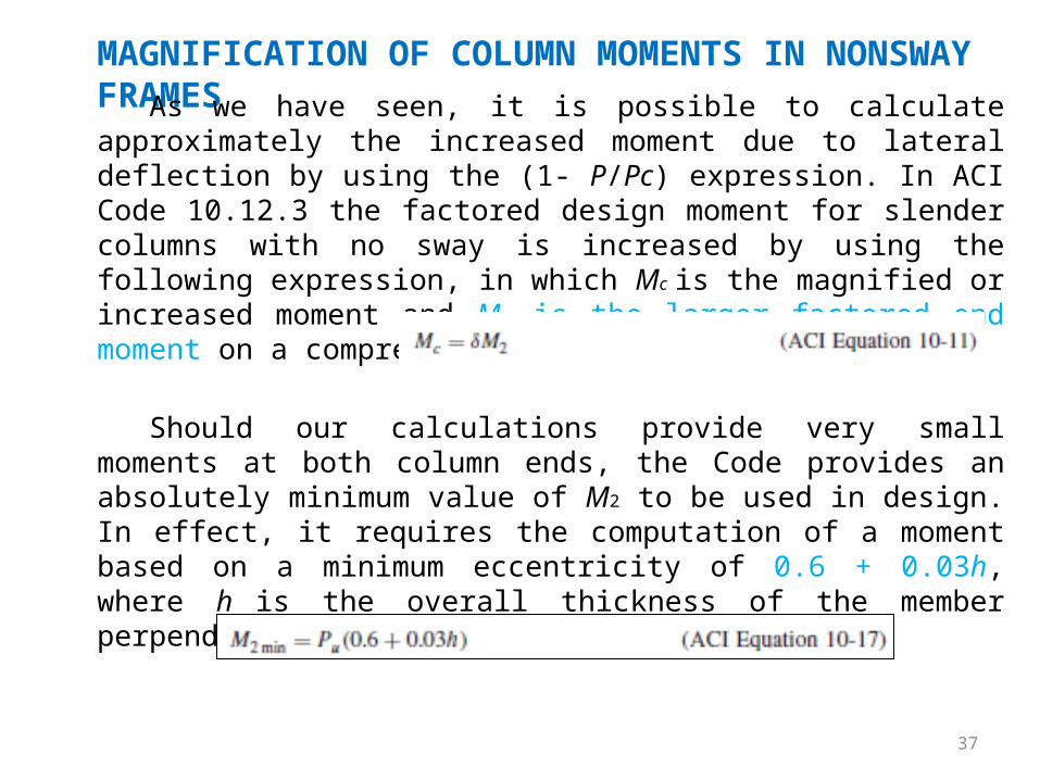
MAGNIFICATION OF COLUMN MOMENTS IN NONSWAY FRAMESAs we have seen, it is possible to calculate approximately the
increased moment due to lateral deflection by using the (1- P/Pc) expression. In ACI Code 10.12.3 the factored design moment for slender columns with no sway is increased by using the following expression, in which Mc is the magnified or increased moment and M2 is the larger factored end moment on a compression member:
Should our calculations provide very small moments at both column ends, the Code provides an absolutely minimum value of M2 to be used in design. In effect, it requires the computation of a moment based on a minimum eccentricity of 0.6 + 0.03h, where h is the overall thickness of the member perpendicular to the axis of bending.
38
MAGNIFICATION OF COLUMN MOMENTS IN NONSWAY FRAMES
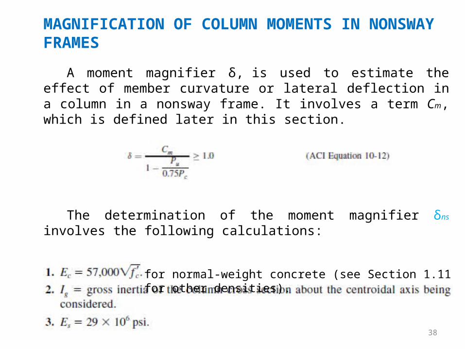
A moment magnifier δ, is used to estimate the effect of member curvature or lateral deflection in a column in a nonsway frame. It involves a term Cm, which is defined later in this section.
The determination of the moment magnifier δns involves the following calculations:
for normal-weight concrete (see Section 1.11 for other densities).
39
MAGNIFICATION OF COLUMN MOMENTS IN NONSWAY FRAMES
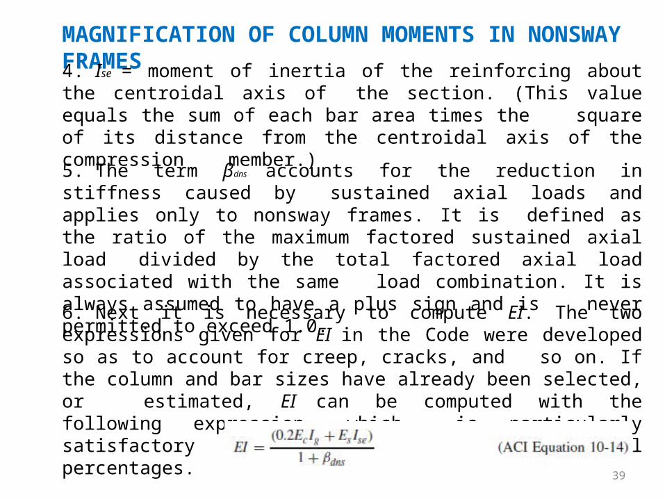
4. Ise = moment of inertia of the reinforcing about the centroidal axis of the section. (This value equals the sum of each bar area times the square of its distance from the centroidal axis of the compression member.)
5. The term βdns accounts for the reduction in stiffness caused by sustained axial loads and applies only to nonsway frames. It is defined as the ratio of the maximum factored sustained axial load divided by the total factored axial load associated with the same load combination. It is always assumed to have a plus sign and is never permitted to exceed 1.0.
6. Next it is necessary to compute EI. The two expressions given for EI in the Code were developed so as to account for creep, cracks, and so on. If the column and bar sizes have already been selected, or estimated, EI can be computed with the following expression, which is particularly satisfactory for columns with high steel percentages.
40
MAGNIFICATION OF COLUMN MOMENTS IN NONSWAY FRAMES
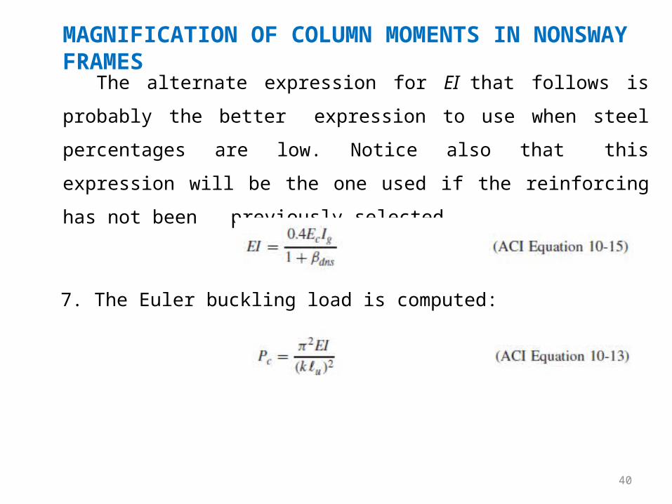
The alternate expression for EI that follows is probably the better
expression to use when steel percentages are low. Notice also that
this expression will be the one used if the reinforcing has not been
previously selected.
7. The Euler buckling load is computed:
41
MAGNIFICATION OF COLUMN MOMENTS IN NONSWAY FRAMES
8. For some moment situations in columns, the amplification or
moment magnifier expression provides moments that are too large. One
such situation occurs when the moment at one end of the member is
zero. For this situation the lateral deflection is actually about half of
the deflection in effect provided by the amplification factor. Should we have
approximately equal end moments that are causing reverse curvature
bending, the deflection at mid-depth and the moment there are close to
zero. As a result of these and other situations, the Code provides a
modification factor (Cm) to be used in the moment expression that will result
in more realistic moment magnification.
42
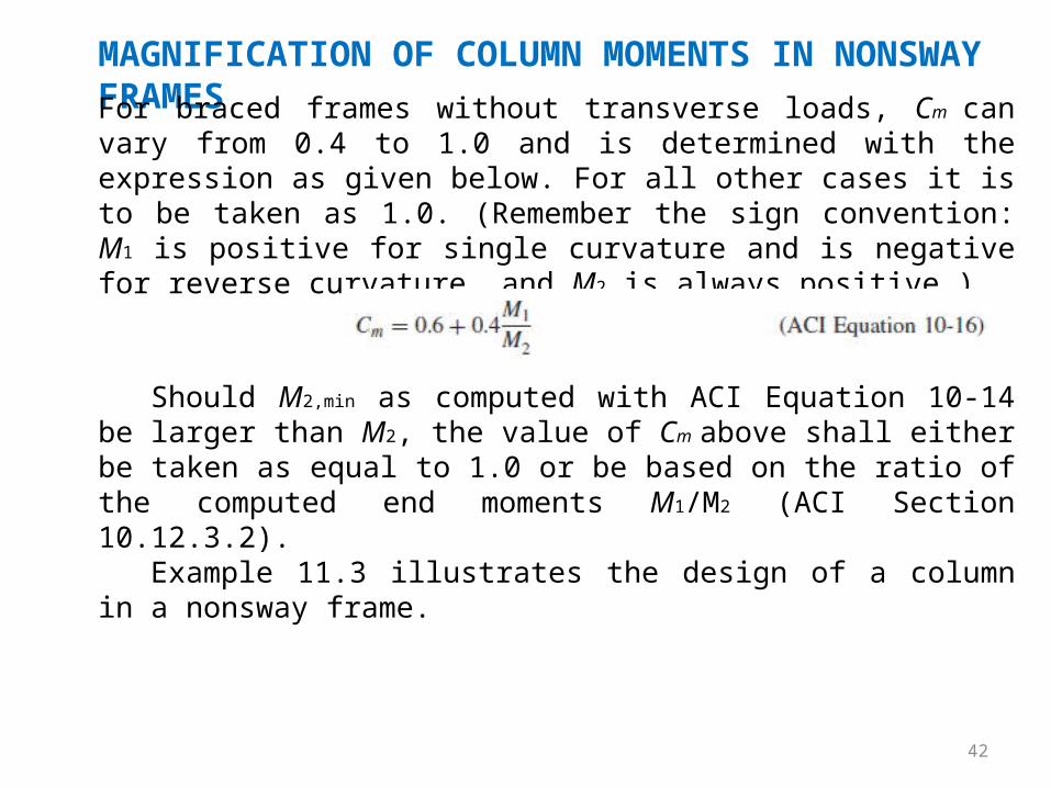
MAGNIFICATION OF COLUMN MOMENTS IN NONSWAY FRAMESFor braced frames without transverse loads, Cm can vary from 0.4 to 1.0 and is determined with the expression as given below. For all other cases it is to be taken as 1.0. (Remember the sign convention: M1 is positive for single curvature and is negative for reverse curvature, and M2 is always positive.)
Should M2,min as computed with ACI Equation 10-14 be larger than M2, the value of Cm above shall either be taken as equal to 1.0 or be based on the ratio of the computed end moments M1/M2 (ACI Section 10.12.3.2).
Example 11.3 illustrates the design of a column in a nonsway frame.
43
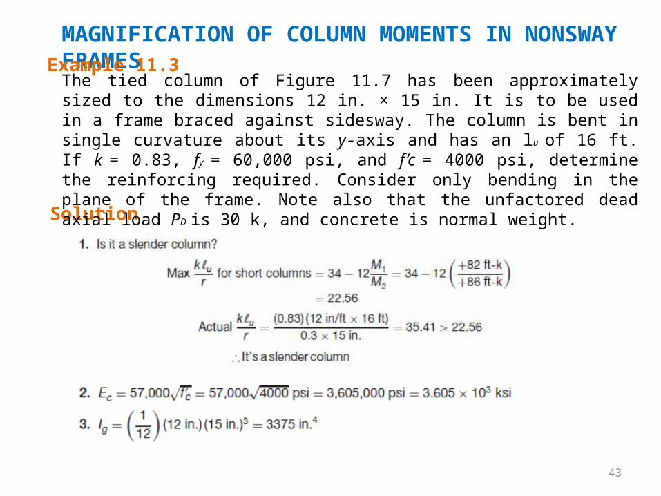
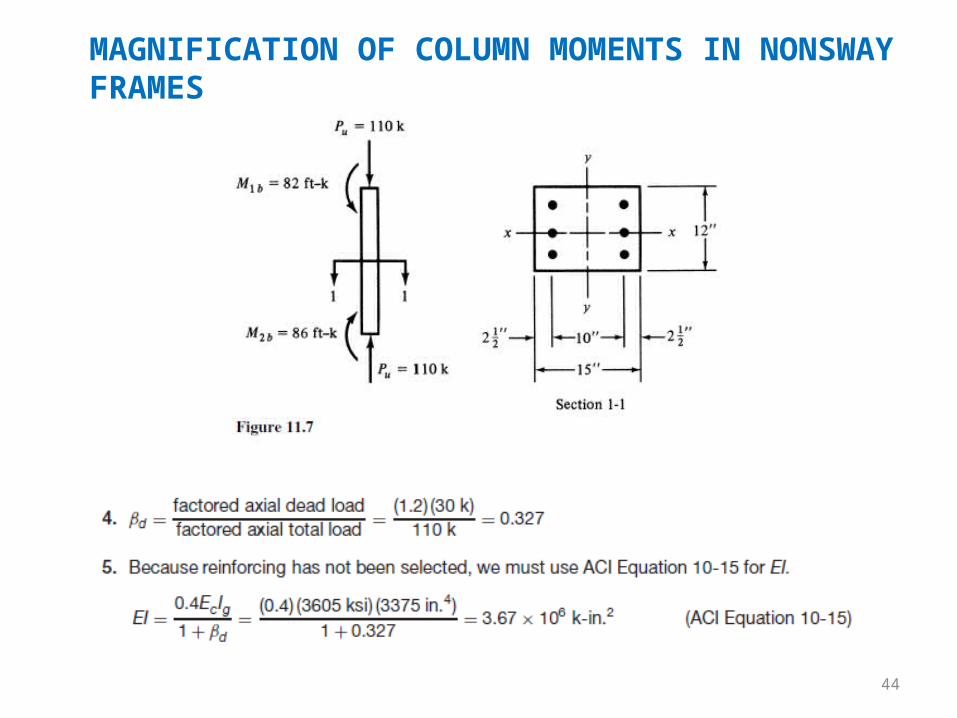
MAGNIFICATION OF COLUMN MOMENTS IN NONSWAY FRAMESExample 11.3
Solution
The tied column of Figure 11.7 has been approximately sized to the dimensions 12 in. × 15 in. It is to be used in a frame braced against sidesway. The column is bent in single curvature about its y-axis and has an lu of 16 ft. If k = 0.83, fy = 60,000 psi, and f’c = 4000 psi, determine the reinforcing required. Consider only bending in the plane of the frame. Note also that the unfactored dead axial load PD is 30 k, and concrete is normal weight.
44
MAGNIFICATION OF COLUMN MOMENTS IN NONSWAY FRAMES
45
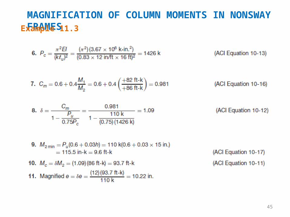
MAGNIFICATION OF COLUMN MOMENTS IN NONSWAY FRAMESExample 11.3
46
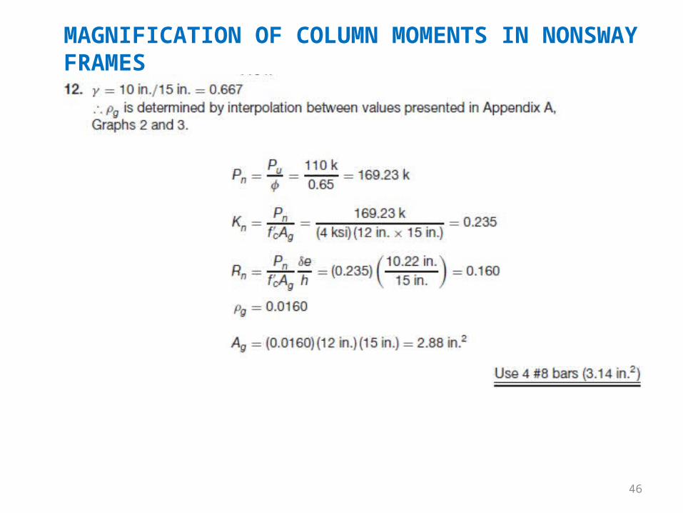
MAGNIFICATION OF COLUMN MOMENTS IN NONSWAY FRAMES
47
MAGNIFICATION OF COLUMN MOMENTS IN NONSWAY FRAMES
Since Kn and Rn are between the radial lines labeled fs/fy = 1.0 and ϵt =
0.005 on the interaction diagrams, the φ factor is permitted to be increased
from the 0.65 value used. An area of reinforcing of only 1.80 in.2 is found to
be sufficient. This significant reduction occurs because of the increased φ
factor in this region.
Most columns are designed for multiple load combinations, and the
designer must be certain that the column is able to resist all of them. Often
there are some columns with high axial load and low moment, such as 1.2D +
1.6L, and others with low axial load and high moment, such as 0.9D + 1.6E.
The first of these is likely to have a φ factor of 0.65. The second, however, is
more likely to be eligible for the increase in the φ factor.

48
MAGNIFICATION OF COLUMN MOMENTS IN SWAY FRAMESTests have shown that even though the lateral deflections in
unbraced frames are rather small, their buckling loads are far less than they would be if the frames had been braced. As a result, the buckling strengths of the columns of an unbraced frame can be decidedly increased (perhaps by as much as two or three times) by providing bracing.
If a frame is unbraced against sidesway, it is first necessary to compute its slenderness ratio. If klu/r is less than 22, slenderness may be neglected (ACI 10.13.2). For this discussion it is assumed that values > 22 are obtained.
When sway frames are involved, it is necessary to decide for each load combination which of the loads cause appreciable sidesway (probably the lateral loads) and which do not. The factored end moments that cause sidesway are referred to as M1s and M2s, and they must be magnified because of the PΔ effect. The other end moments, which do not cause appreciable sidesway, are M1ns and M2ns. They are determined by first-order analysis and will not have to be magnified.
49
MAGNIFICATION OF COLUMN MOMENTS IN SWAY FRAMES
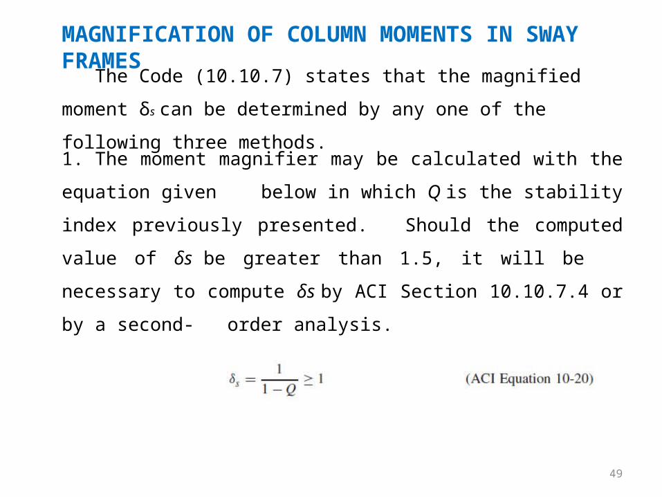
The Code (10.10.7) states that the magnified moment δs can be
determined by any one of the following three methods.
1. The moment magnifier may be calculated with the equation given
below in which Q is the stability index previously presented.
Should the computed value of δs be greater than 1.5, it will be
necessary to compute δs by ACI Section 10.10.7.4 or by a second-
order analysis.
50
MAGNIFICATION OF COLUMN MOMENTS IN SWAY FRAMES
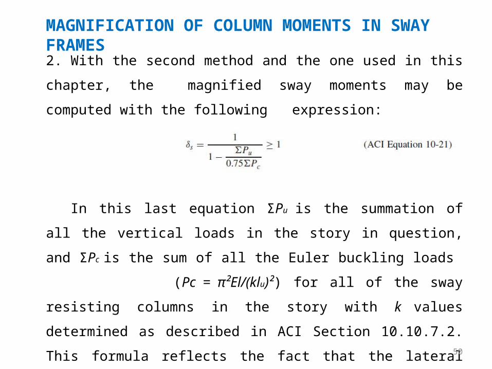
In this last equation ΣPu is the summation of all the vertical loads
in the story in question, and ΣPc is the sum of all the Euler buckling loads
(Pc = π²El/(klu)²) for all of the sway resisting columns in the story with
k values determined as described in ACI Section 10.10.7.2. This formula
reflects the fact that the lateral deflections of all the columns in a
particular story are equal, and thus the columns are interactive.
2. With the second method and the one used in this chapter, the
magnified sway moments may be computed with the following
expression:
51
MAGNIFICATION OF COLUMN MOMENTS IN SWAY FRAMES
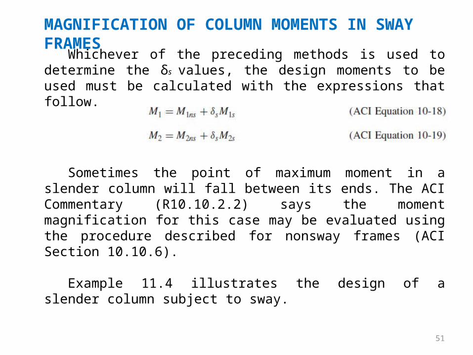
Whichever of the preceding methods is used to determine the δs values, the design moments to be used must be calculated with the expressions that follow.
Sometimes the point of maximum moment in a slender column will fall between its ends. The ACI Commentary (R10.10.2.2) says the moment magnification for this case may be evaluated using the procedure described for nonsway frames (ACI Section 10.10.6).
Example 11.4 illustrates the design of a slender column subject to sway.
52
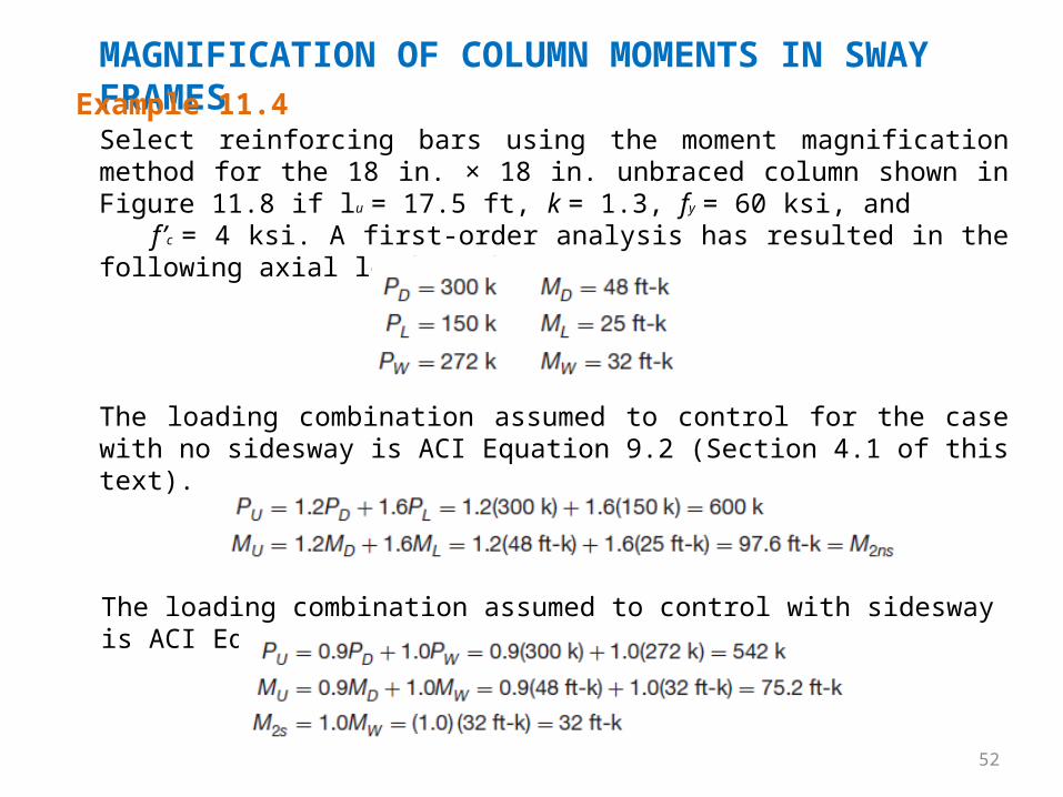
MAGNIFICATION OF COLUMN MOMENTS IN SWAY FRAMESExample 11.4Select reinforcing bars using the moment magnification method for the 18 in. × 18 in. unbraced column shown in Figure 11.8 if lu = 17.5 ft, k = 1.3, fy = 60 ksi, and f’c = 4 ksi. A first-order analysis has resulted in the following axial loads and moments:
The loading combination assumed to control with sidesway is ACI Equation 9.6.
The loading combination assumed to control for the case with no sidesway is ACI Equation 9.2 (Section 4.1 of this text).
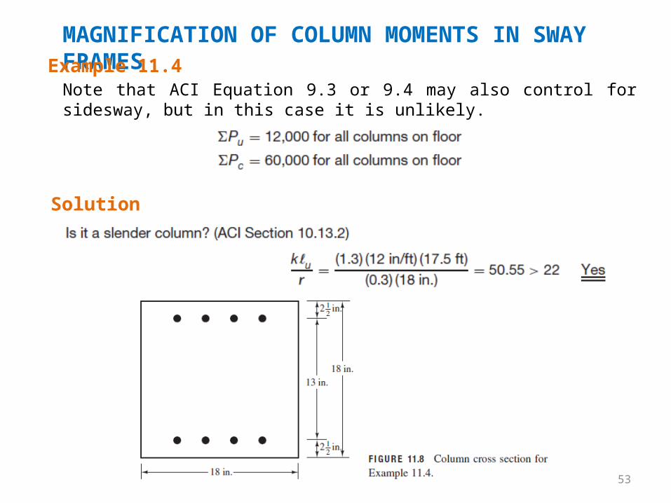
53
MAGNIFICATION OF COLUMN MOMENTS IN SWAY FRAMESExample 11.4Note that ACI Equation 9.3 or 9.4 may also control for sidesway, but in this case it is unlikely.
Solution
54
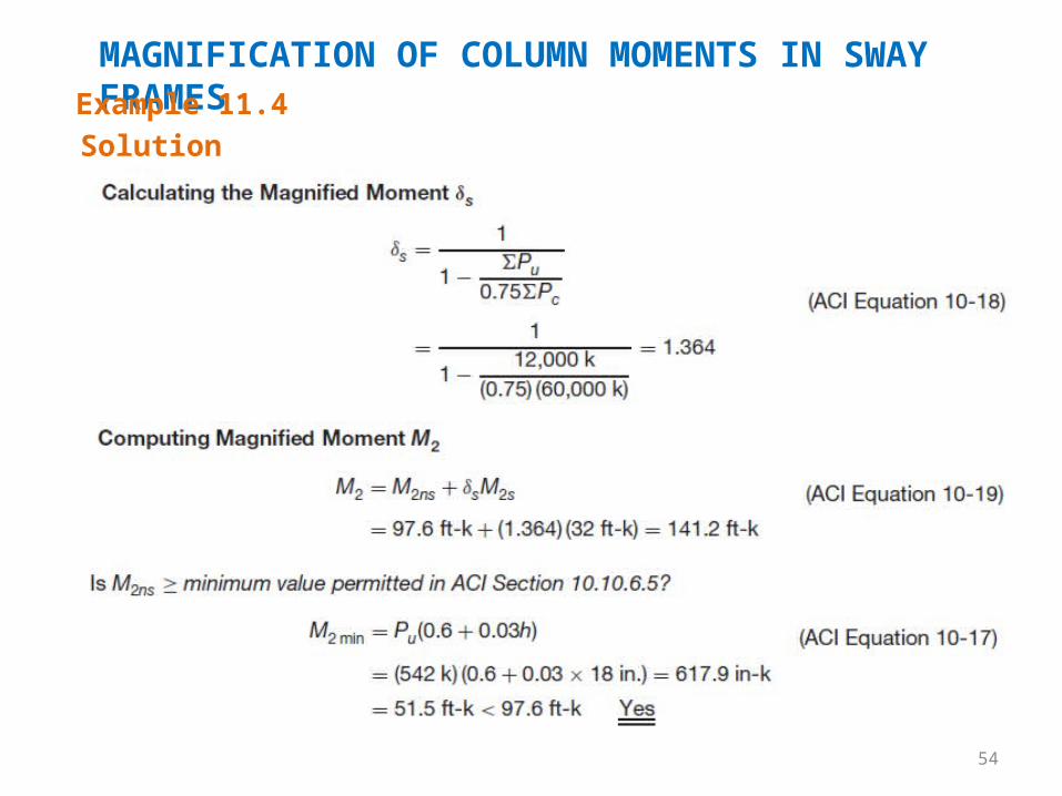
MAGNIFICATION OF COLUMN MOMENTS IN SWAY FRAMESExample 11.4Solution
55
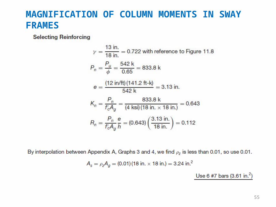
MAGNIFICATION OF COLUMN MOMENTS IN SWAY FRAMES
56
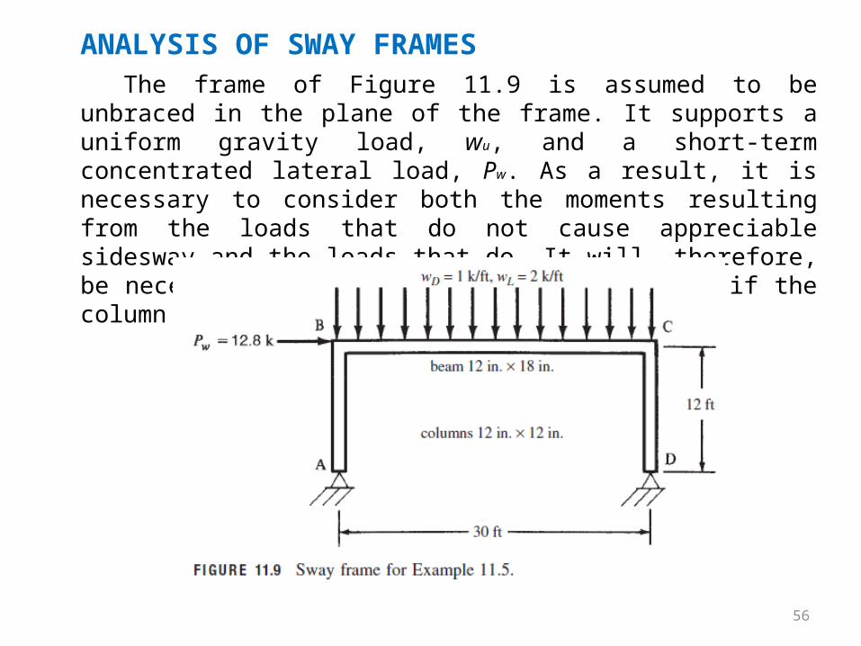
ANALYSIS OF SWAY FRAMESThe frame of Figure 11.9 is assumed to be unbraced in the plane
of the frame. It supports a uniform gravity load, wu, and a short-term concentrated lateral load, Pw. As a result, it is necessary to consider both the moments resulting from the loads that do not cause appreciable sidesway and the loads that do. It will, therefore, be necessary to compute both δ and δs values, if the column proves to be slender.

57
58
ANALYSIS OF SWAY FRAMES
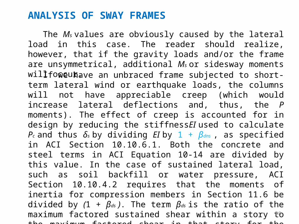
The Ms values are obviously caused by the lateral load in this case. The reader should realize, however, that if the gravity loads and/or the frame are unsymmetrical, additional Ms or sidesway moments will occur.
If we have an unbraced frame subjected to short-term lateral wind or earthquake loads, the columns will not have appreciable creep (which would increase lateral deflections and, thus, the P moments). The effect of creep is accounted for in design by reducing the stiffnessEI used to calculate Pc and thus δs by dividing EI by 1 + βdns , as specified in ACI Section 10.10.6.1. Both the concrete and steel terms in ACI Equation 10-14 are divided by this value. In the case of sustained lateral load, such as soil backfill or water pressure, ACI Section 10.10.4.2 requires that the moments of inertia for compression members in Section 11.6 be divided by (1 + βds ). The term βds is the ratio of the maximum factored sustained shear within a story to the maximum factored shear in that story for the same load combination.
59
ANALYSIS OF SWAY FRAMES
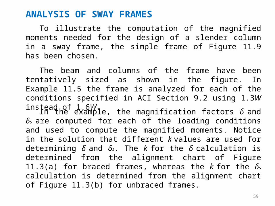
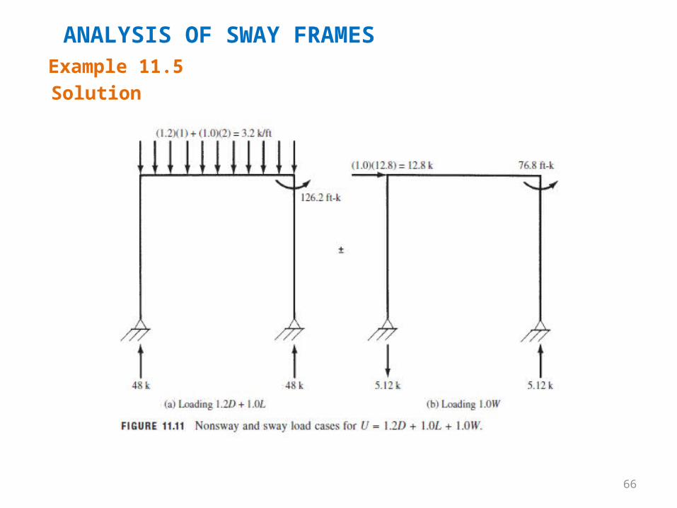
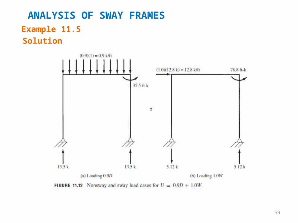
The beam and columns of the frame have been tentatively sized as shown in the figure. In Example 11.5 the frame is analyzed for each of the conditions specified in ACI Section 9.2 using 1.3W instead of 1.6W.
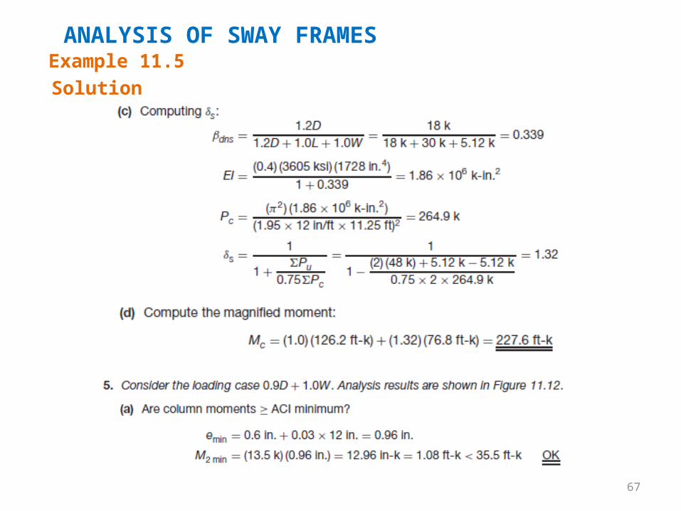
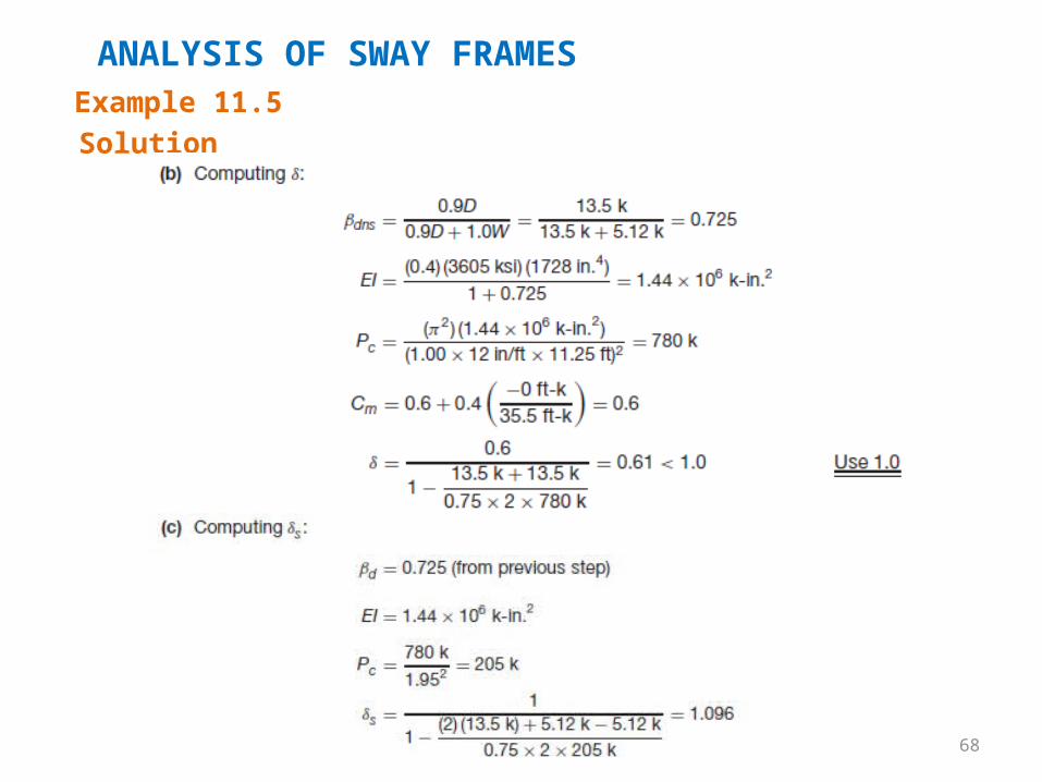
In the example, the magnification factors δ and δs are computed for each of the loading conditions and used to compute the magnified moments. Notice in the solution that different k values are used for determining δ and δs. The k for the δ calculation is determined from the alignment chart of Figure 11.3(a) for braced frames, whereas the k for the δs calculation is determined from the alignment chart of Figure 11.3(b) for unbraced frames.
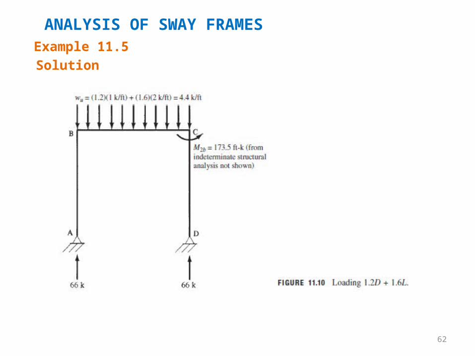
To illustrate the computation of the magnified moments needed for the design of a slender column in a sway frame, the simple frame of Figure 11.9 has been chosen.
60
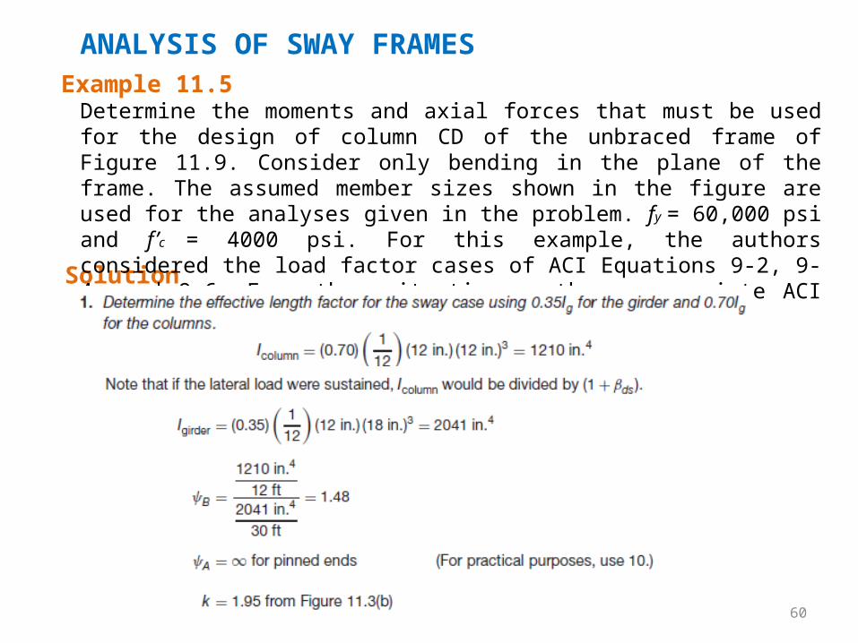
ANALYSIS OF SWAY FRAMESExample 11.5
Solution
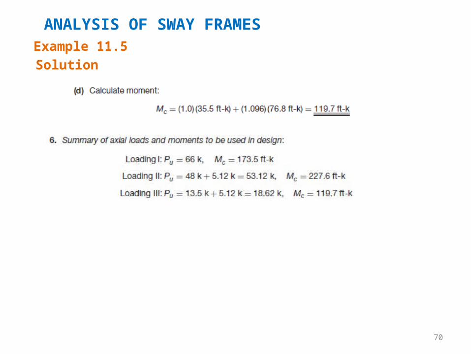
Determine the moments and axial forces that must be used for the design of column CD of the unbraced frame of Figure 11.9. Consider only bending in the plane of the frame. The assumed member sizes shown in the figure are used for the analyses given in the problem. fy = 60,000 psi and f’c = 4000 psi. For this example, the authors considered the load factor cases of ACI Equations 9-2, 9-4, and 9-6. For other situations, other appropriate ACI load factor equations will have to be considered.
61
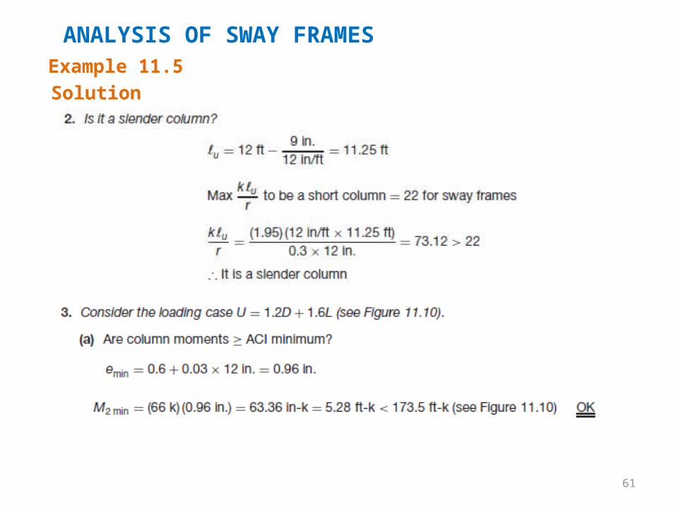
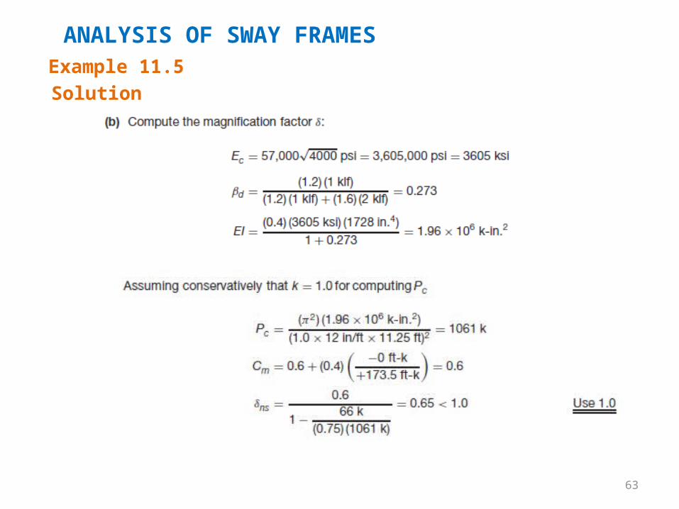
ANALYSIS OF SWAY FRAMESExample 11.5Solution
62
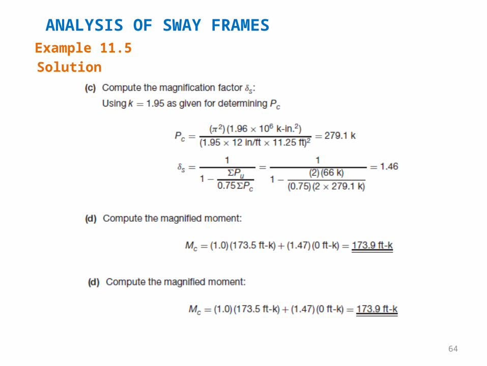
ANALYSIS OF SWAY FRAMESExample 11.5Solution
63
ANALYSIS OF SWAY FRAMESExample 11.5Solution
64
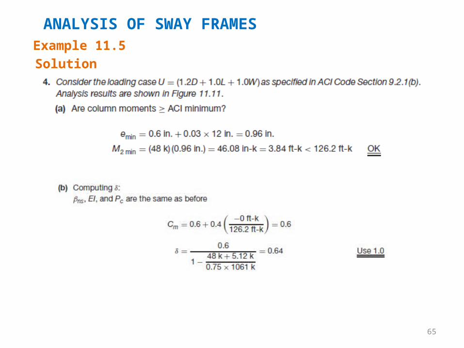
ANALYSIS OF SWAY FRAMESExample 11.5Solution
65
ANALYSIS OF SWAY FRAMESExample 11.5Solution
66
ANALYSIS OF SWAY FRAMESExample 11.5Solution
67
ANALYSIS OF SWAY FRAMESExample 11.5Solution
68
ANALYSIS OF SWAY FRAMESExample 11.5Solution
69
ANALYSIS OF SWAY FRAMESExample 11.5Solution
70
ANALYSIS OF SWAY FRAMESExample 11.5Solution