Embed Size (px)
Citation preview
MODEL NO. PAGE EVERVISION
VGG644803-6UFLWB SPEC SAMPLE 2
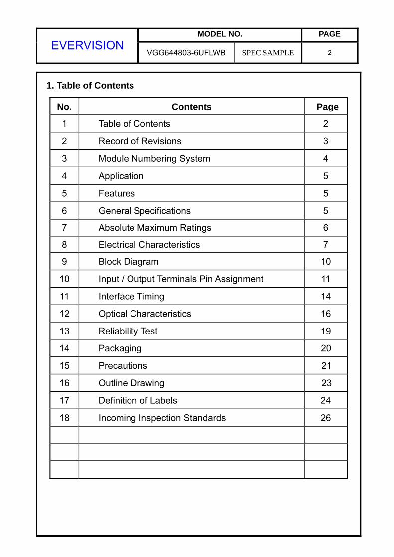
1. Table of Contents
No. Contents Page
1 Table of Contents 2
2 Record of Revisions 3
3 Module Numbering System 4
4 Application 5
5 Features 5
6 General Specifications 5
7 Absolute Maximum Ratings 6
8 Electrical Characteristics 7
9 Block Diagram 10
10 Input / Output Terminals Pin Assignment 11
11 Interface Timing 14
12 Optical Characteristics 16
13 Reliability Test 19
14 Packaging 20
15 Precautions 21
16 Outline Drawing 23
17 Definition of Labels 24
18 Incoming Inspection Standards 26
MODEL NO. PAGE EVERVISION
VGG644803-6UFLWB SPEC SAMPLE 3
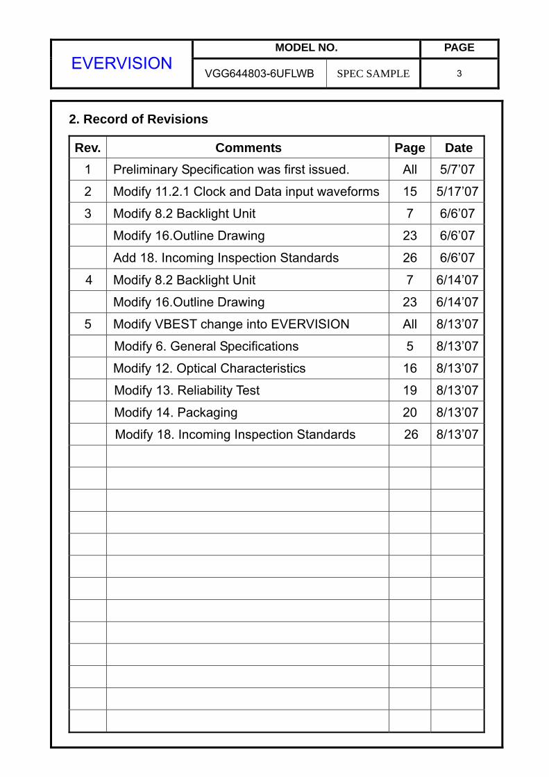
2. Record of Revisions
Rev. Comments Page Date 1 Preliminary Specification was first issued. All 5/7’07
2 Modify 11.2.1 Clock and Data input waveforms 15 5/17’07
3 Modify 8.2 Backlight Unit 7 6/6’07
Modify 16.Outline Drawing 23 6/6’07
Add 18. Incoming Inspection Standards 26 6/6’07
4 Modify 8.2 Backlight Unit 7 6/14’07
Modify 16.Outline Drawing 23 6/14’07
5 Modify VBEST change into EVERVISION All 8/13’07
Modify 6. General Specifications 5 8/13’07
Modify 12. Optical Characteristics 16 8/13’07
Modify 13. Reliability Test 19 8/13’07
Modify 14. Packaging 20 8/13’07
Modify 18. Incoming Inspection Standards 26 8/13’07
MODEL NO. PAGE EVERVISION
VGG644803-6UFLWB SPEC SAMPLE 4
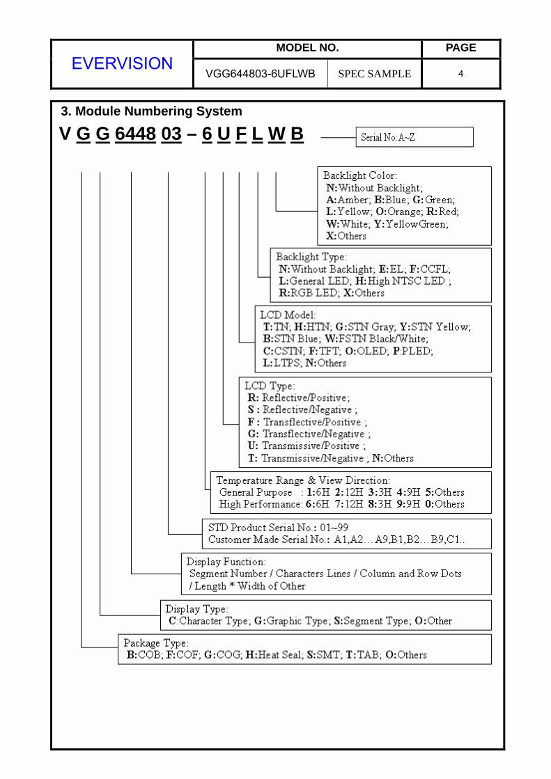
V G G 6448 03 – 6 U F L W B3. Module Numbering System
MODEL NO. PAGE EVERVISION
VGG644803-6UFLWB SPEC SAMPLE 5
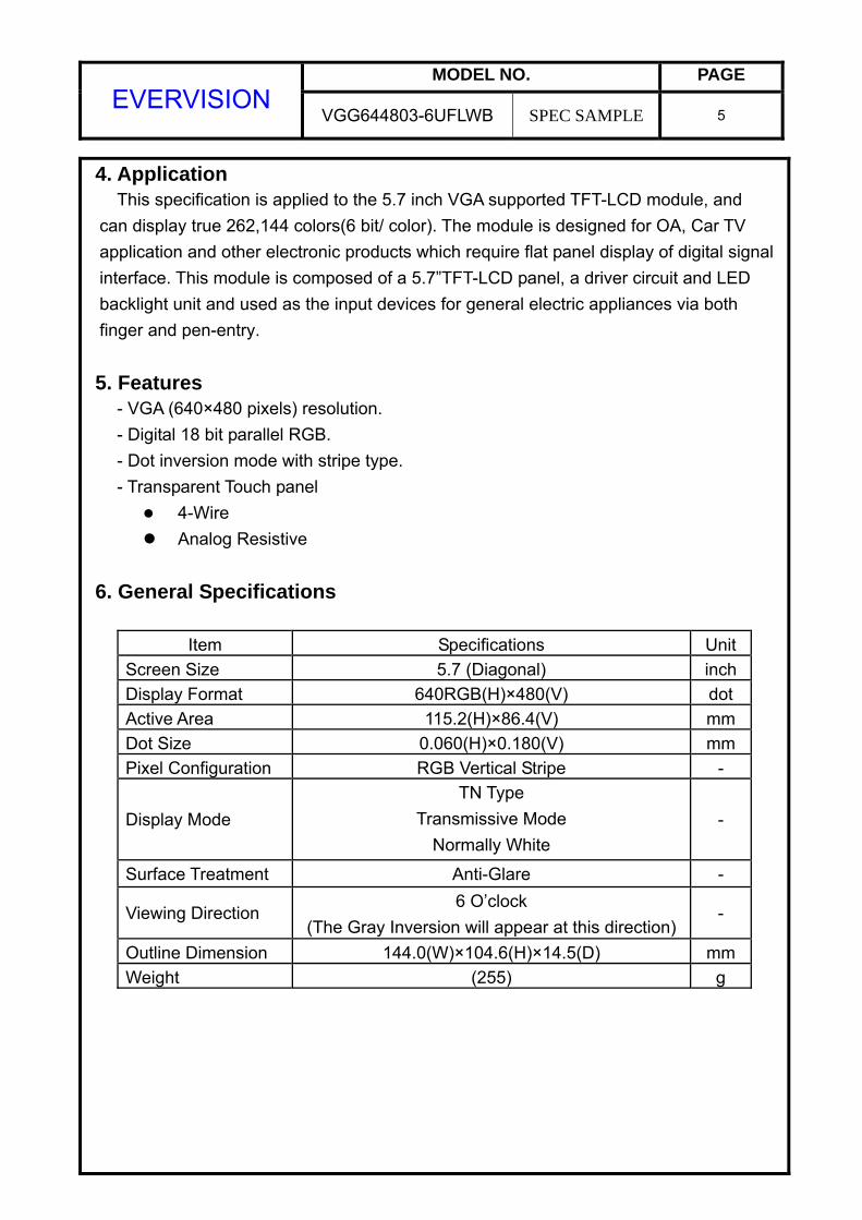
4. Application This specification is applied to the 5.7 inch VGA supported TFT-LCD module, and can display true 262,144 colors(6 bit/ color). The module is designed for OA, Car TV application and other electronic products which require flat panel display of digital signal
interface. This module is composed of a 5.7”TFT-LCD panel, a driver circuit and LED backlight unit and used as the input devices for general electric appliances via both finger and pen-entry.
5. Features
- VGA (640×480 pixels) resolution. - Digital 18 bit parallel RGB. - Dot inversion mode with stripe type. - Transparent Touch panel
4-Wire
Analog Resistive
6. General Specifications
Item Specifications Unit Screen Size 5.7 (Diagonal) inch Display Format 640RGB(H)×480(V) dot Active Area 115.2(H)×86.4(V) mm Dot Size 0.060(H)×0.180(V) mm Pixel Configuration RGB Vertical Stripe -
Display Mode TN Type
Transmissive Mode Normally White
-
Surface Treatment Anti-Glare -
Viewing Direction 6 O’clock
(The Gray Inversion will appear at this direction) -
Outline Dimension 144.0(W)×104.6(H)×14.5(D) mm Weight (255) g
MODEL NO. PAGE EVERVISION
VGG644803-6UFLWB SPEC SAMPLE 6
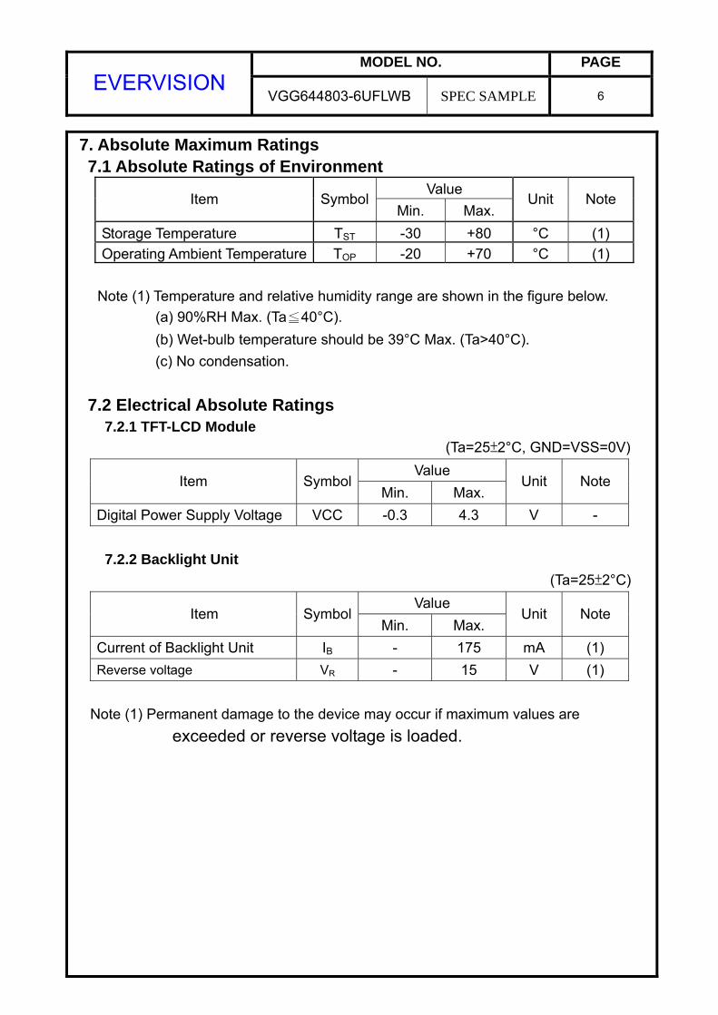
7. Absolute Maximum Ratings 7.1 Absolute Ratings of Environment
Value Item Symbol
Min. Max. Unit Note
Storage Temperature TST -30 +80 °C (1) Operating Ambient Temperature TOP -20 +70 °C (1)
Note (1) Temperature and relative humidity range are shown in the figure below. (a) 90%RH Max. (Ta≦40°C). (b) Wet-bulb temperature should be 39°C Max. (Ta>40°C). (c) No condensation.
7.2 Electrical Absolute Ratings 7.2.1 TFT-LCD Module (Ta=25±2°C, GND=VSS=0V)
Value Item Symbol
Min. Max. Unit Note
Digital Power Supply Voltage VCC -0.3 4.3 V - 7.2.2 Backlight Unit
(Ta=25±2°C) Value
Item SymbolMin. Max.
Unit Note
Current of Backlight Unit IB - 175 mA (1) Reverse voltage VR - 15 V (1)
Note (1) Permanent damage to the device may occur if maximum values are
exceeded or reverse voltage is loaded.
MODEL NO. PAGE EVERVISION
VGG644803-6UFLWB SPEC SAMPLE 7
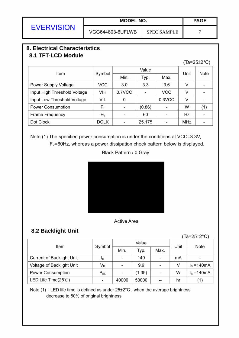
8. Electrical Characteristics 8.1 TFT-LCD Module
(Ta=25±2°C) Value
Item SymbolMin. Typ. Max.
Unit Note
Power Supply Voltage VCC 3.0 3.3 3.6 V -
Input High Threshold Voltage VIH 0.7VCC - VCC V -
Input Low Threshold Voltage VIL 0 - 0.3VCC V -
Power Consumption PL - (0.86) - W (1)
Frame Frequency FV - 60 - Hz -
Dot Clock DCLK - 25.175 - MHz -
Note (1) The specified power consumption is under the conditions at VCC=3.3V, FV=60Hz, whereas a power dissipation check pattern below is displayed.
8.2 Backlight Unit (Ta=25±2°C)
Value Item Symbol
Min. Typ. Max. Unit Note
Current of Backlight Unit IB - 140 - mA -
Voltage of Backlight Unit VB - 9.9 - V IB =140mA
Power Consumption PBL - (1.39) - W IB =140mALED Life Time(25) - 40000 50000 -- hr (1)
Note (1):LED life time is defined as under 25±2°C , when the average brightness decrease to 50% of original brightness
Active Area
Black Pattern / 0 Gray
MODEL NO. PAGE EVERVISION
VGG644803-6UFLWB SPEC SAMPLE 8
8.3 Transparent Touch panel Electrical characteristics
Value Item
Min. Typ. Max. Unit Note
Operating Voltage - 5 7 V -
X-direction 270 470 600 Ω At connector Terminal Resistance Y-direction 240 310 500 Ω At connector
Insulation Resistance ≧ 20MΩ At DC25V
Linearity ≦1.5% (1)
Chatting ≦ 10 ms At connector
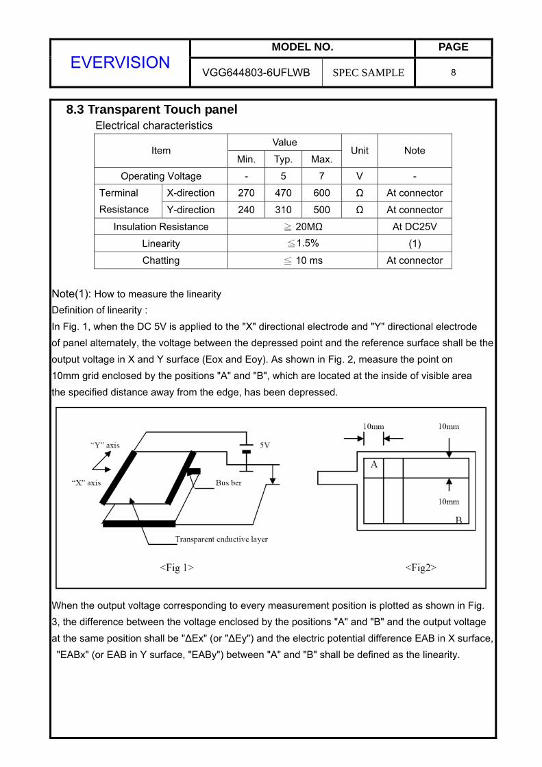
Note(1): How to measure the linearity Definition of linearity : In Fig. 1, when the DC 5V is applied to the "X" directional electrode and "Y" directional electrode of panel alternately, the voltage between the depressed point and the reference surface shall be theoutput voltage in X and Y surface (Eox and Eoy). As shown in Fig. 2, measure the point on 10mm grid enclosed by the positions "A" and "B", which are located at the inside of visible area the specified distance away from the edge, has been depressed.
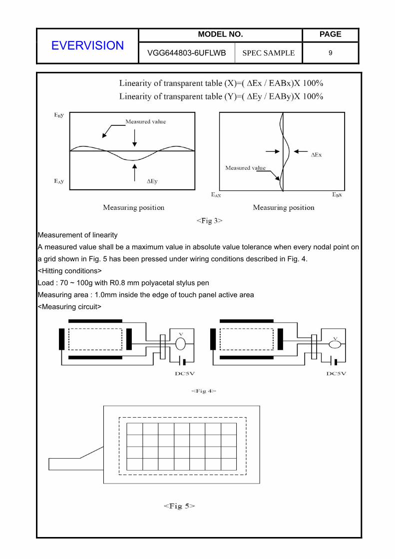
When the output voltage corresponding to every measurement position is plotted as shown in Fig. 3, the difference between the voltage enclosed by the positions "A" and "B" and the output voltage at the same position shall be "ΔEx" (or "ΔEy") and the electric potential difference EAB in X surface, "EABx" (or EAB in Y surface, "EABy") between "A" and "B" shall be defined as the linearity.
MODEL NO. PAGE EVERVISION
VGG644803-6UFLWB SPEC SAMPLE 9
Measurement of linearity A measured value shall be a maximum value in absolute value tolerance when every nodal point ona grid shown in Fig. 5 has been pressed under wiring conditions described in Fig. 4. <Hitting conditions> Load : 70 ~ 100g with R0.8 mm polyacetal stylus pen Measuring area : 1.0mm inside the edge of touch panel active area <Measuring circuit>
MODEL NO. PAGE EVERVISION
VGG644803-6UFLWB SPEC SAMPLE 10
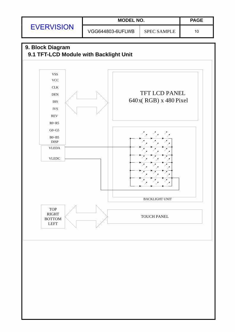
9. Block Diagram 9.1 TFT-LCD Module with Backlight Unit
TFT LCD PANEL640 x ( RGB) x 480 Pixel
BACKLIGHT UNIT
VSS
VCC
CLK
DEN
IHS
IVS
REV
R0~R5
G0~G5
B0~B5DISP
VLEDC
VLEDA
TOUCH PANEL
TOPRIGHT
BOTTOMLEFT
MODEL NO. PAGE EVERVISION
VGG644803-6UFLWB SPEC SAMPLE 11
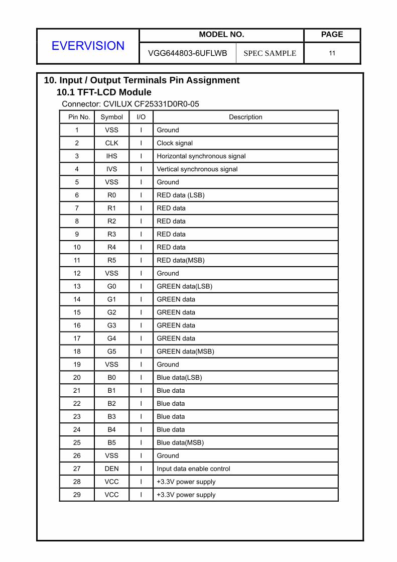
10. Input / Output Terminals Pin Assignment 10.1 TFT-LCD Module Connector: CVILUX CF25331D0R0-05
Pin No. Symbol I/O Description
1 VSS I Ground
2 CLK I Clock signal
3 IHS I Horizontal synchronous signal
4 IVS I Vertical synchronous signal
5 VSS I Ground
6 R0 I RED data (LSB)
7 R1 I RED data 8 R2 I RED data 9 R3 I RED data 10 R4 I RED data 11 R5 I RED data(MSB)
12 VSS I Ground
13 G0 I GREEN data(LSB)
14 G1 I GREEN data 15 G2 I GREEN data 16 G3 I GREEN data 17 G4 I GREEN data 18 G5 I GREEN data(MSB)
19 VSS I Ground
20 B0 I Blue data(LSB)
21 B1 I Blue data 22 B2 I Blue data 23 B3 I Blue data 24 B4 I Blue data 25 B5 I Blue data(MSB) 26 VSS I Ground
27 DEN I Input data enable control
28 VCC I +3.3V power supply
29 VCC I +3.3V power supply
MODEL NO. PAGE EVERVISION
VGG644803-6UFLWB SPEC SAMPLE 12
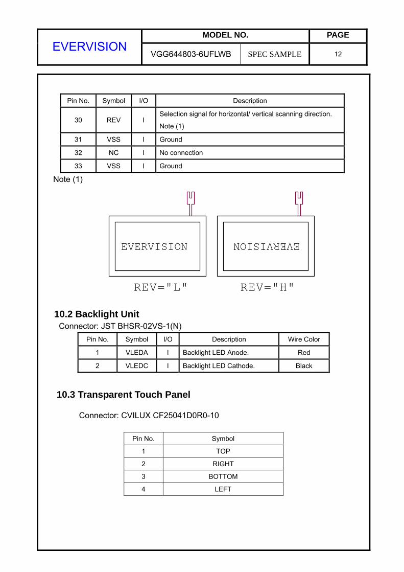
Pin No. Symbol I/O Description
30 REV I Selection signal for horizontal/ vertical scanning direction.
Note (1)
31 VSS I Ground
32 NC I No connection
33 VSS I Ground
Note (1)
EVERVISIONEVERVISION
REV="H"REV="L"
10.2 Backlight Unit Connector: JST BHSR-02VS-1(N)
Pin No. Symbol I/O Description Wire Color
1 VLEDA I Backlight LED Anode. Red
2 VLEDC I Backlight LED Cathode. Black
10.3 Transparent Touch Panel
Connector: CVILUX CF25041D0R0-10
Pin No. Symbol
1 TOP
2 RIGHT
3 BOTTOM
4 LEFT
MODEL NO. PAGE EVERVISION
VGG644803-6UFLWB SPEC SAMPLE 13
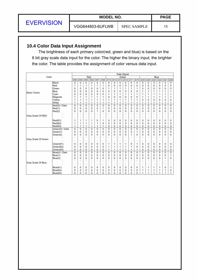
10.4 Color Data Input Assignment The brightness of each primary color(red, green and blue) is based on the 6 bit gray scale data input for the color. The higher the binary input, the brighter the color. The table provides the assignment of color versus data input.
Data Signal
Red Green Blue Color D05 D04 D03 D02 D01 D00 D15 D14 D13 D12 D11 D10 D25 D24 D23 D22 D21 D20
Black 0 0 0 0 0 0 0 0 0 0 0 0 0 0 0 0 0 0Red 1 1 1 1 1 1 0 0 0 0 0 0 0 0 0 0 0 0Green 0 0 0 0 0 0 1 1 1 1 1 1 0 0 0 0 0 0Blue 0 0 0 0 0 0 0 0 0 0 0 0 1 1 1 1 1 1Cyan 0 0 0 0 0 0 1 1 1 1 1 1 1 1 1 1 1 1Magenta 1 1 1 1 1 1 0 0 0 0 0 0 1 1 1 1 1 1Yellow 1 1 1 1 1 1 1 1 1 1 1 1 0 0 0 0 0 0
Basic Colors
White 1 1 1 1 1 1 1 1 1 1 1 1 1 1 1 1 1 1Red(0) / Dark 0 0 0 0 0 0 0 0 0 0 0 0 0 0 0 0 0 0Red(1) 0 0 0 0 0 1 0 0 0 0 0 0 0 0 0 0 0 0Red(2) 0 0 0 0 1 0 0 0 0 0 0 0 0 0 0 0 0 0
: : : : : : : : : : : : : : : : : : :
: : : : : : : : : : : : : : : : : : :
Red(61) 1 1 1 1 0 1 0 0 0 0 0 0 0 0 0 0 0 0Red(62) 1 1 1 1 1 0 0 0 0 0 0 0 0 0 0 0 0 0
Gray Scale Of RED
Red(63) 1 1 1 1 1 1 0 0 0 0 0 0 0 0 0 0 0 0Green(0) / Dark 0 0 0 0 0 0 0 0 0 0 0 0 0 0 0 0 0 0Green(1) 0 0 0 0 0 0 0 0 0 0 0 1 0 0 0 0 0 0Green(2) 0 0 0 0 0 0 0 0 0 0 1 0 0 0 0 0 0 0
: : : : : : : : : : : : : : : : : : :
: : : : : : : : : : : : : : : : : : :
Green(61) 0 0 0 0 0 0 1 1 1 1 0 1 0 0 0 0 0 0Green(62) 0 0 0 0 0 0 1 1 1 1 1 0 0 0 0 0 0 0
Gray Scale Of Green
Green(63) 0 0 0 0 0 0 1 1 1 1 1 1 0 0 0 0 0 0Blue(0) / Dark 0 0 0 0 0 0 0 0 0 0 0 0 0 0 0 0 0 0Blue(1) 0 0 0 0 0 0 0 0 0 0 0 0 0 0 0 0 0 1Blue(2) 0 0 0 0 0 0 0 0 0 0 0 0 0 0 0 0 1 0
: : : : : : : : : : : : : : : : : : :
: : : : : : : : : : : : : : : : : : :
Blue(61) 0 0 0 0 0 0 0 0 0 0 0 0 1 1 1 1 0 1Blue(62) 0 0 0 0 0 0 0 0 0 0 0 0 1 1 1 1 1 0
Gray Scale Of Blue
Blue(63) 0 0 0 0 0 0 0 0 0 0 0 0 1 1 1 1 1 1
MODEL NO. PAGE EVERVISION
VGG644803-6UFLWB SPEC SAMPLE 14
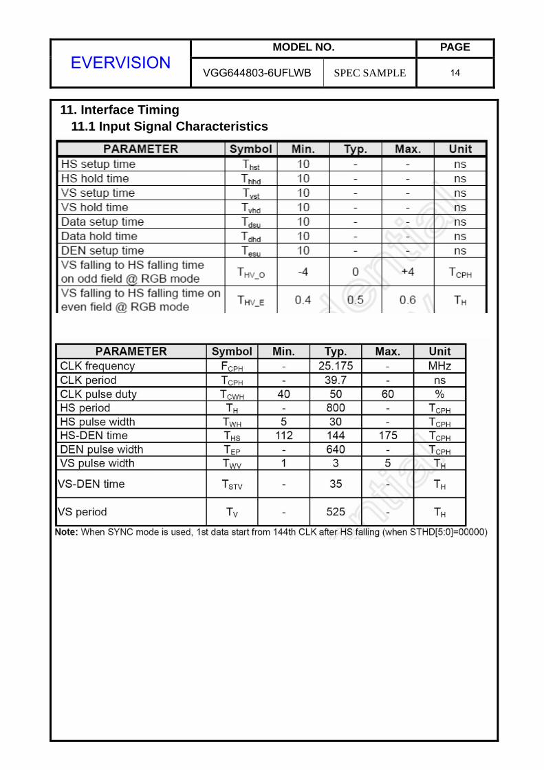
11. Interface Timing 11.1 Input Signal Characteristics
MODEL NO. PAGE EVERVISION
VGG644803-6UFLWB SPEC SAMPLE 15
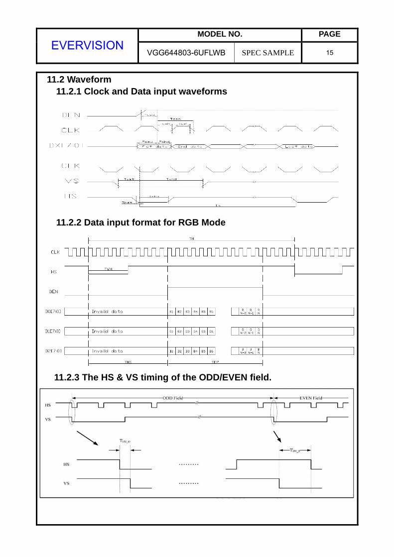
11.2 Waveform 11.2.1 Clock and Data input waveforms
11.2.2 Data input format for RGB Mode
11.2.3 The HS & VS timing of the ODD/EVEN field.
MODEL NO. PAGE EVERVISION
VGG644803-6UFLWB SPEC SAMPLE 16
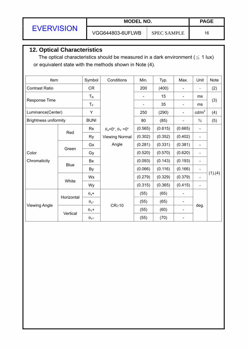
12. Optical Characteristics The optical characteristics should be measured in a dark environment ( 1 lux)≦
or equivalent state with the methods shown in Note (4).
Item Symbol Conditions Min. Typ. Max. Unit Note
Contrast Ratio CR 200 (400) - - (2)
TR - 15 - ms Response Time
TF - 35 - ms (3)
Luminance(Center) Y 250 (290) - cd/m2 (4)
Brightness uniformity BUNI 80 (85) - % (5)
Rx (0.565) (0.615) (0.665) - Red
Ry (0.302) (0.352) (0.402) -
Gx (0.281) (0.331) (0.381) - Green
Gy (0.520) (0.570) (0.620) -
Bx (0.093) (0.143) (0.193) - Blue
By (0.066) (0.116) (0.166) -
Wx (0.279) (0.329) (0.379) -
Color
Chromaticity
White Wy
θx=0°, θY =0°
Viewing Normal
Angle
(0.315) (0.365) (0.415) -
θx+ (55) (65) - Horizontal
θx- (55) (65) -
θY+ (55) (60) - Viewing Angle
Vertical θY-
CR≥10
(55) (70) -
deg.
(1),(4)
MODEL NO. PAGE EVERVISION
VGG644803-6UFLWB SPEC SAMPLE 17
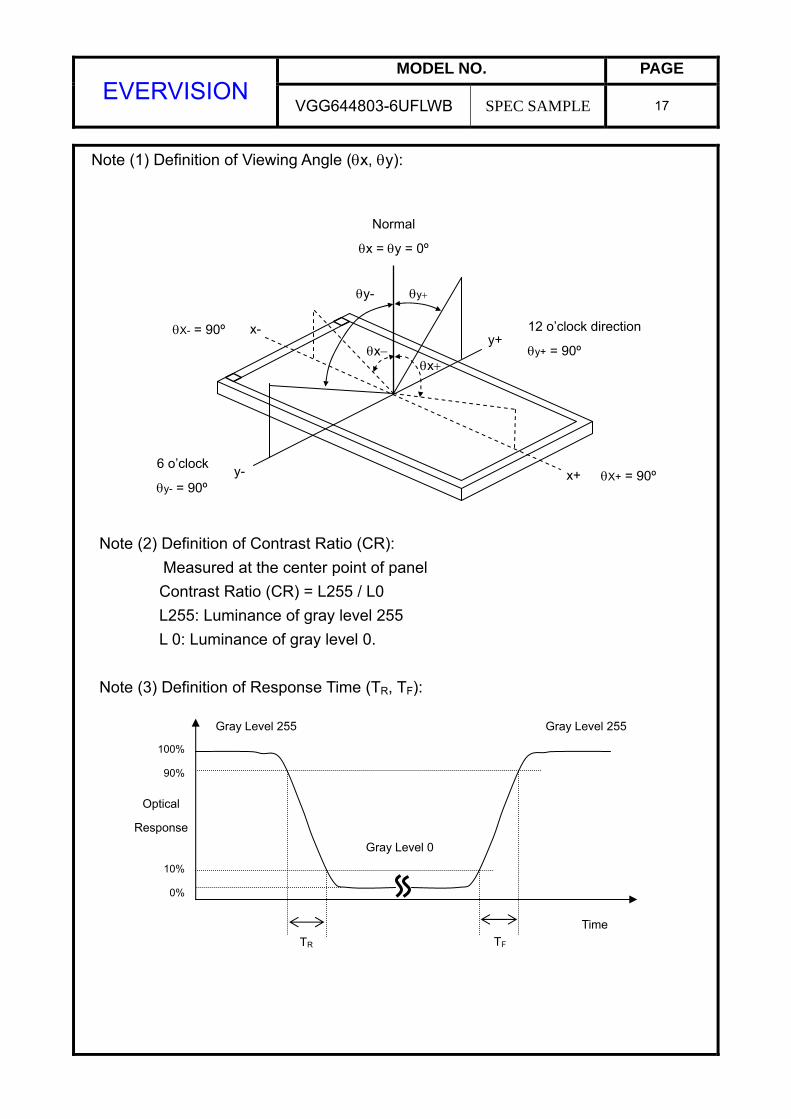
Note (1) Definition of Viewing Angle (θx, θy): Note (2) Definition of Contrast Ratio (CR):
Measured at the center point of panel Contrast Ratio (CR) = L255 / L0 L255: Luminance of gray level 255 L 0: Luminance of gray level 0.
Note (3) Definition of Response Time (TR, TF):
12 o’clock direction
θy+ = 90º
6 o’clock
θy- = 90º
θx− θx+
θy- θy+
x- y+
y- x+
Normal
θx = θy = 0º
θX+ = 90º
θX- = 90º
100%
90%
10%
0%
Gray Level 255
Gray Level 0
Gray Level 255
Time TF
Optical
Response
TR
MODEL NO. PAGE EVERVISION
VGG644803-6UFLWB SPEC SAMPLE 18
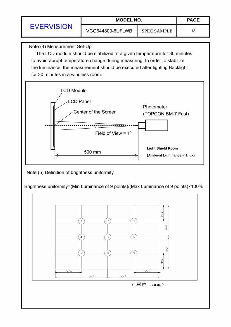
Note (4) Measurement Set-Up: The LCD module should be stabilized at a given temperature for 30 minutes
to avoid abrupt temperature change during measuring. In order to stabilize the luminance, the measurement should be executed after lighting Backlight for 30 minutes in a windless room.
Note (5) Definition of brightness uniformity Brightness uniformity=(Min Luminance of 9 points)/(Max Luminance of 9 points)×100%
Photometer (TOPCON BM-7 Fast)
Field of View = 1º
500 mm
LCD Module
LCD Panel
Center of the Screen
Light Shield Room
(Ambient Luminance < 1 lux)
MODEL NO. PAGE EVERVISION
VGG644803-6UFLWB SPEC SAMPLE 19
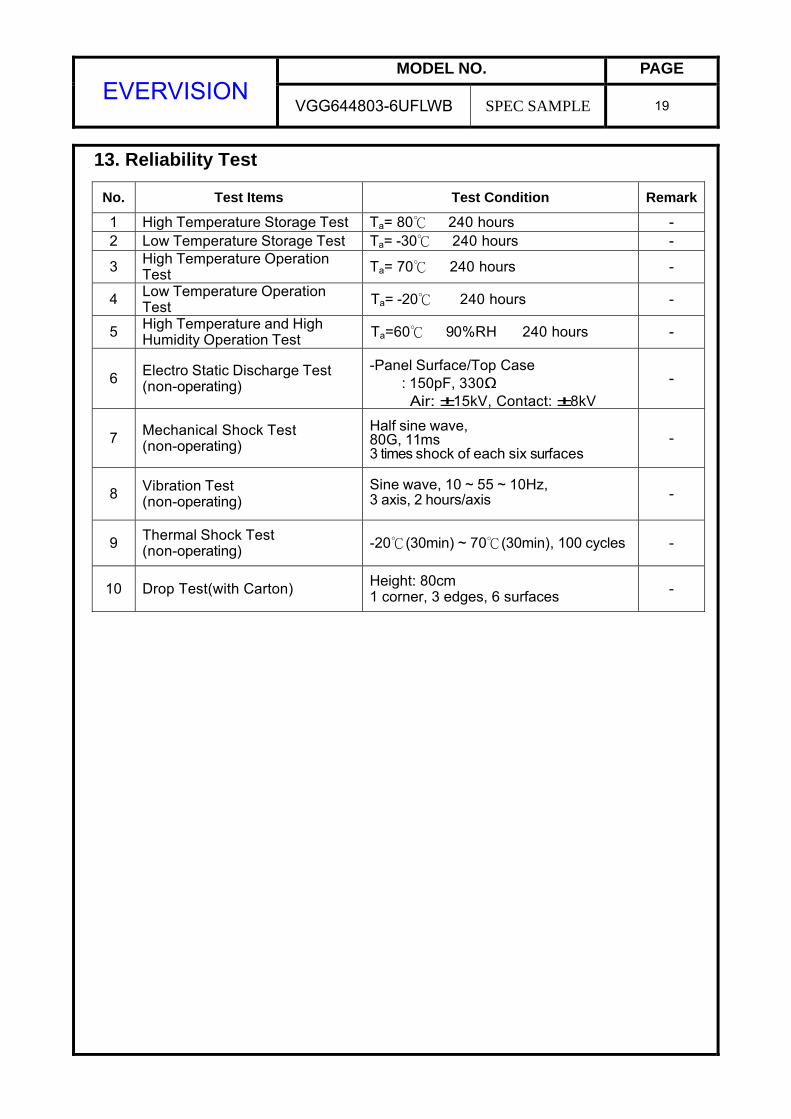
13. Reliability Test
No. Test Items Test Condition Remark
1 High Temperature Storage Test Ta= 80 240 hours - 2 Low Temperature Storage Test Ta= -30 240 hours -
3 High Temperature Operation Test Ta= 70 240 hours -
4 Low Temperature Operation Test Ta= -20 240 hours -
5 High Temperature and High Humidity Operation Test Ta=60 90%RH 240 hours -
6 Electro Static Discharge Test (non-operating)
-Panel Surface/Top Case : 150pF, 330Ω Air: ±15kV, Contact: ±8kV
-
7 Mechanical Shock Test (non-operating)
Half sine wave, 80G, 11ms 3 times shock of each six surfaces
-
8 Vibration Test (non-operating)
Sine wave, 10 ~ 55 ~ 10Hz, 3 axis, 2 hours/axis -
9 Thermal Shock Test (non-operating) -20(30min) ~ 70(30min), 100 cycles -
10 Drop Test(with Carton) Height: 80cm 1 corner, 3 edges, 6 surfaces -
MODEL NO. PAGE EVERVISION
VGG644803-6UFLWB SPEC SAMPLE 20
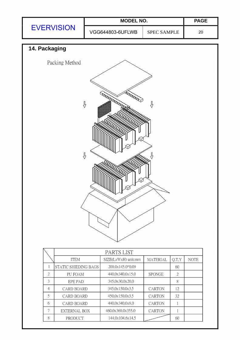
14. Packaging

MODEL NO. PAGE EVERVISION
VGG644803-6UFLWB SPEC SAMPLE 21
15. Precautions 15.1 Assembly and Handling Precautions
(1) Do not apply rough force such as bending or twisting to the module during assembly. (2) It’s recommended to assemble or to install a module into the user’s system
in clean working areas. The dust and oil may cause electrical short or worsen the polarizer.
(3) Don’t apply pressure or impulse to the module to prevent the damage of LCD panel and Backlight.
(4) Always follow the correct power-on sequence when the LCD module is turned on. This can prevent the damage and latch-up of the CMOS LSI chips. (5) Do not plug in or pull out the I/F connector while the module is in operation. (6) Do not disassemble the module. (7) Use a soft dry cloth without chemicals for cleaning, because the surface of
polarizer is very soft and easily scratched. (8) Moisture can easily penetrate into LCD module and may cause the damage during operation. (9) High temperature or humidity may deteriorate the performance of LCD module.
Please store LCD module in the specified storage conditions. (10) When ambient temperature is lower than 10ºC, the display quality might be
reduced. For example, the response time will become slow.
15.2 Safety Precautions (1) If the liquid crystal material leaks from the panel, it should be kept away from
the eyes or mouth. In case of contact with hands, skin or clothes, it has to be washed away thoroughly with soap.
(2) After the module’s end of life, it is not harmful in case of normal operation and storage.
MODEL NO. PAGE EVERVISION
VGG644803-6UFLWB SPEC SAMPLE 22
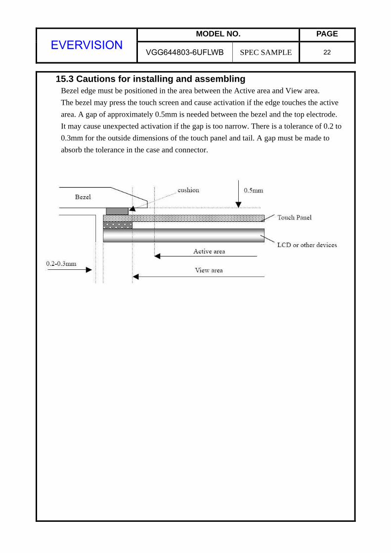
15.3 Cautions for installing and assembling Bezel edge must be positioned in the area between the Active area and View area. The bezel may press the touch screen and cause activation if the edge touches the active area. A gap of approximately 0.5mm is needed between the bezel and the top electrode. It may cause unexpected activation if the gap is too narrow. There is a tolerance of 0.2 to 0.3mm for the outside dimensions of the touch panel and tail. A gap must be made to absorb the tolerance in the case and connector.
MODEL NO. PAGE EVERVISION
VGG644803-6UFLWB SPEC SAMPLE 23
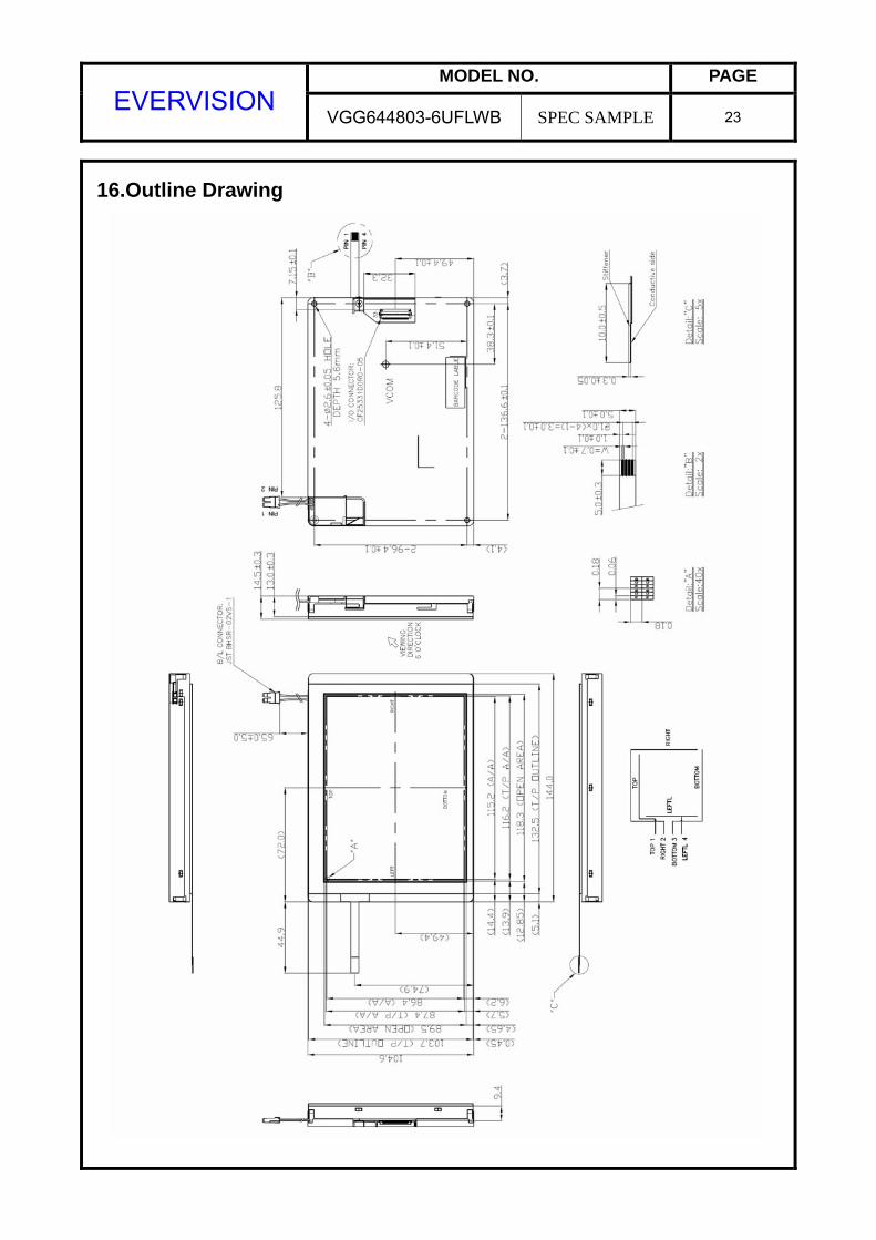
16.Outline Drawing
MODEL NO. PAGE EVERVISION
VGG644803-6UFLWB SPEC SAMPLE 24
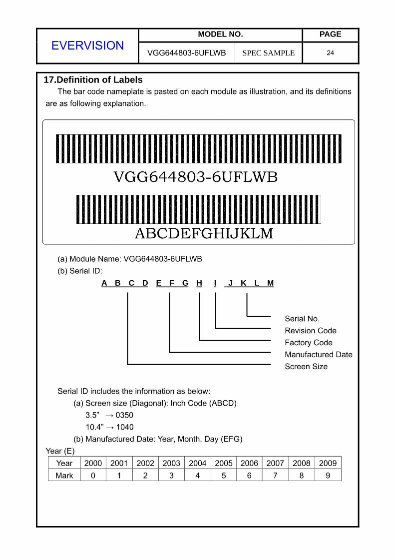
17.Definition of Labels The bar code nameplate is pasted on each module as illustration, and its definitions are as following explanation.
(a) Module Name: VGG644803-6UFLWB (b) Serial ID:
A B C D E F G H I J K L M Serial No. Revision Code Factory Code Manufactured Date Screen Size
Serial ID includes the information as below:
(a) Screen size (Diagonal): Inch Code (ABCD) 3.5” → 0350 10.4” → 1040
(b) Manufactured Date: Year, Month, Day (EFG) Year (E)
Year 2000 2001 2002 2003 2004 2005 2006 2007 2008 2009Mark 0 1 2 3 4 5 6 7 8 9
MODEL NO. PAGE EVERVISION
VGG644803-6UFLWB SPEC SAMPLE 25
Month (F)
Month Jan. Feb. Mar. Apr. May Jun. Jul. Aug. Sep. Oct. Nov. Dec.
Mark 1 2 3 4 5 6 7 8 9 A B C Day (G)
Day 1 2 3 4 5 6 7 8 9 10 11 12 13 14 15 16Mark 1 2 3 4 5 6 7 8 9 A B C D E F GDay 17 18 19 20 21 22 23 24 25 26 27 28 29 30 31 Mark H I J K L M N O P Q R S T U V
(c) Factory Code (H):
For EVERVISION internal use.
(d) Revision Code (I): Cover all the change, for example: 1: Rev.1, 2: Rev.2, 3: Rev.3…etc.
(e) Serial No. (JKLM):
Manufacturing sequence of product, for example: 0001~9999.
MODEL NO. PAGE EVERVISION
VGG644803-6UFLWB SPEC SAMPLE 26
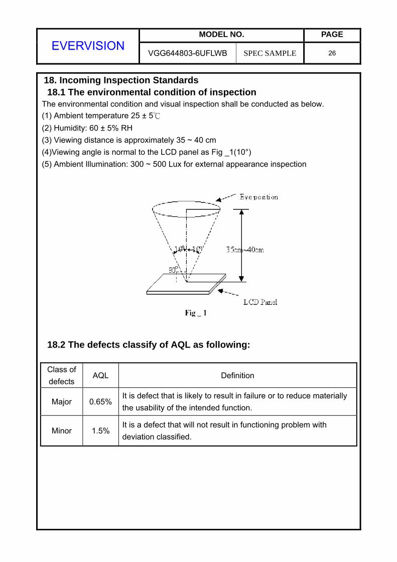
18. Incoming Inspection Standards 18.1 The environmental condition of inspection The environmental condition and visual inspection shall be conducted as below.
(1) Ambient temperature 25 ± 5
(2) Humidity: 60 ± 5% RH
(3) Viewing distance is approximately 35 ~ 40 cm (4)Viewing angle is normal to the LCD panel as Fig _1(10°) (5) Ambient Illumination: 300 ~ 500 Lux for external appearance inspection
18.2 The defects classify of AQL as following:
Class of defects
AQL Definition
Major 0.65% It is defect that is likely to result in failure or to reduce materially the usability of the intended function.
Minor 1.5% It is a defect that will not result in functioning problem with deviation classified.
MODEL NO. PAGE EVERVISION
VGG644803-6UFLWB SPEC SAMPLE 27
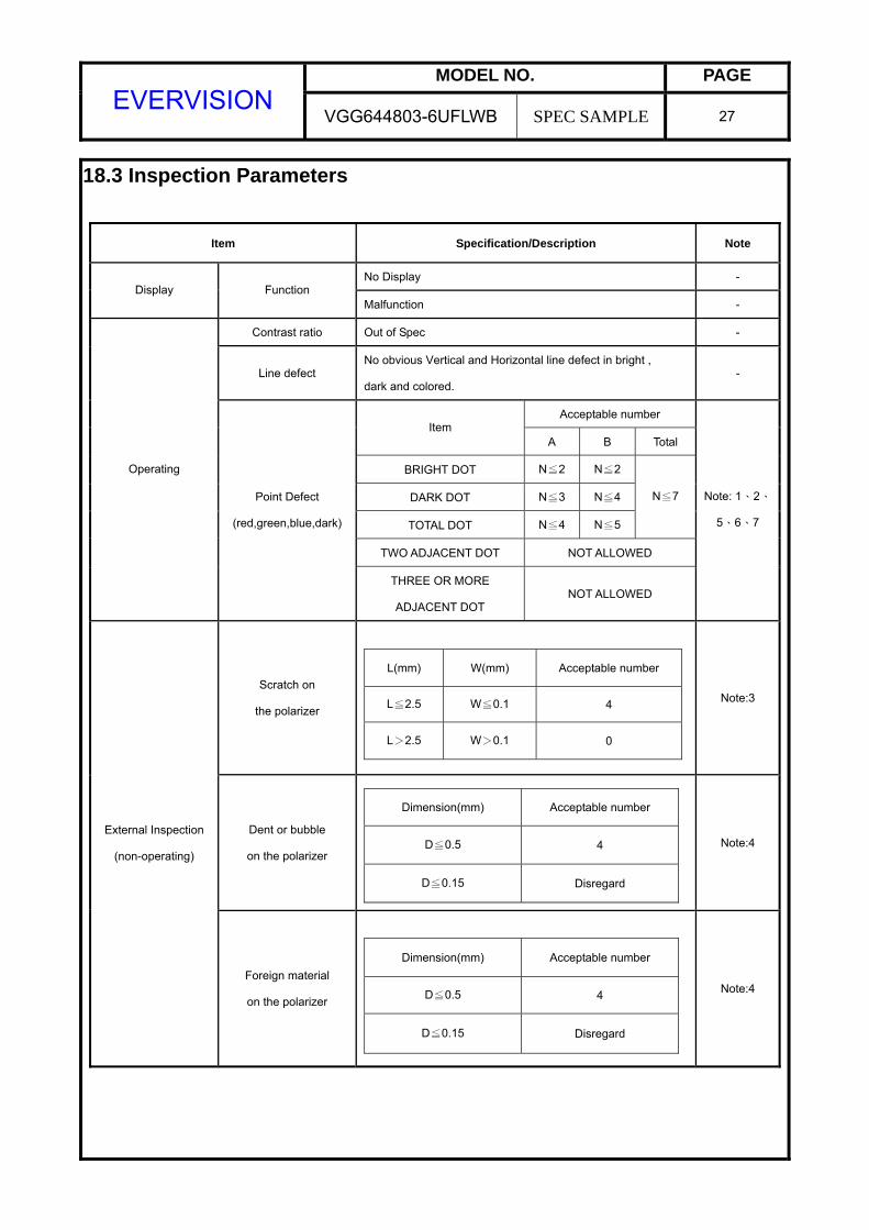
18.3 Inspection Parameters
Item Specification/Description Note
No Display - Display Function
Malfunction -
Contrast ratio Out of Spec -
Line defect No obvious Vertical and Horizontal line defect in bright ,
dark and colored. -
Acceptable number Item
A B Total
BRIGHT DOT N≦2 N≦2
DARK DOT N≦3 N≦4
TOTAL DOT N≦4 N≦5
N≦7
TWO ADJACENT DOT NOT ALLOWED
Operating
Point Defect
(red,green,blue,dark)
THREE OR MORE
ADJACENT DOT NOT ALLOWED
Note: 1、2、
5、6、7
Scratch on
the polarizer
L(mm) W(mm) Acceptable number
L≦2.5 W≦0.1 4
L>2.5 W>0.1 0
Note:3
Dent or bubble
on the polarizer
Dimension(mm) Acceptable number
D≦0.5 4
D≦0.15 Disregard
Note:4 External Inspection
(non-operating)
Foreign material
on the polarizer
Dimension(mm) Acceptable number
D≦0.5 4
D≦0.15 Disregard
Note:4
MODEL NO. PAGE EVERVISION
VGG644803-6UFLWB SPEC SAMPLE 28
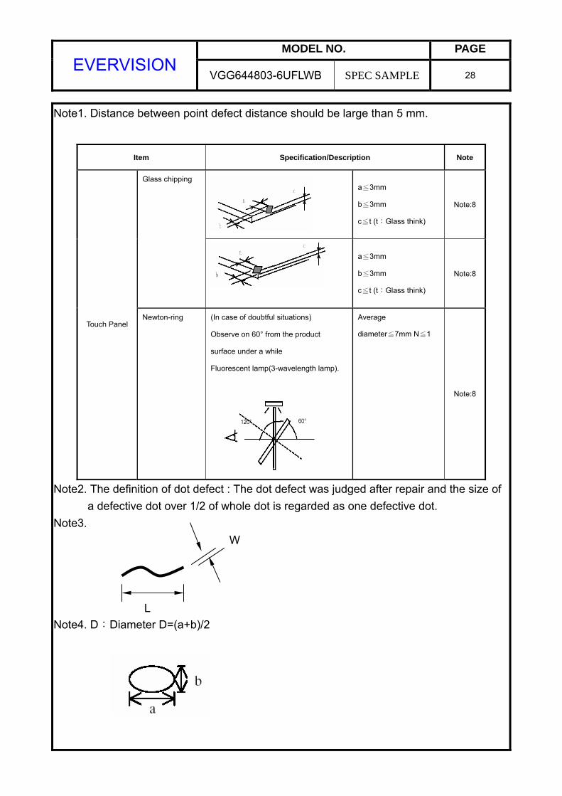
Note1. Distance between point defect distance should be large than 5 mm.
Note2. The definition of dot defect : The dot defect was judged after repair and the size of a defective dot over 1/2 of whole dot is regarded as one defective dot. Note3.
W
L Note4. D:Diameter D=(a+b)/2
Item Specification/Description Note
a≦3mm
b≦3mm
c≦t (t:Glass think)
Note:8
Glass chipping
a≦3mm
b≦3mm
c≦t (t:Glass think)
Note:8
Touch Panel Newton-ring (In case of doubtful situations)
Observe on 60° from the product
surface under a while
Fluorescent lamp(3-wavelength lamp).
Average
diameter≦7mm N≦1
Note:8
MODEL NO. PAGE EVERVISION
VGG644803-6UFLWB SPEC SAMPLE 29
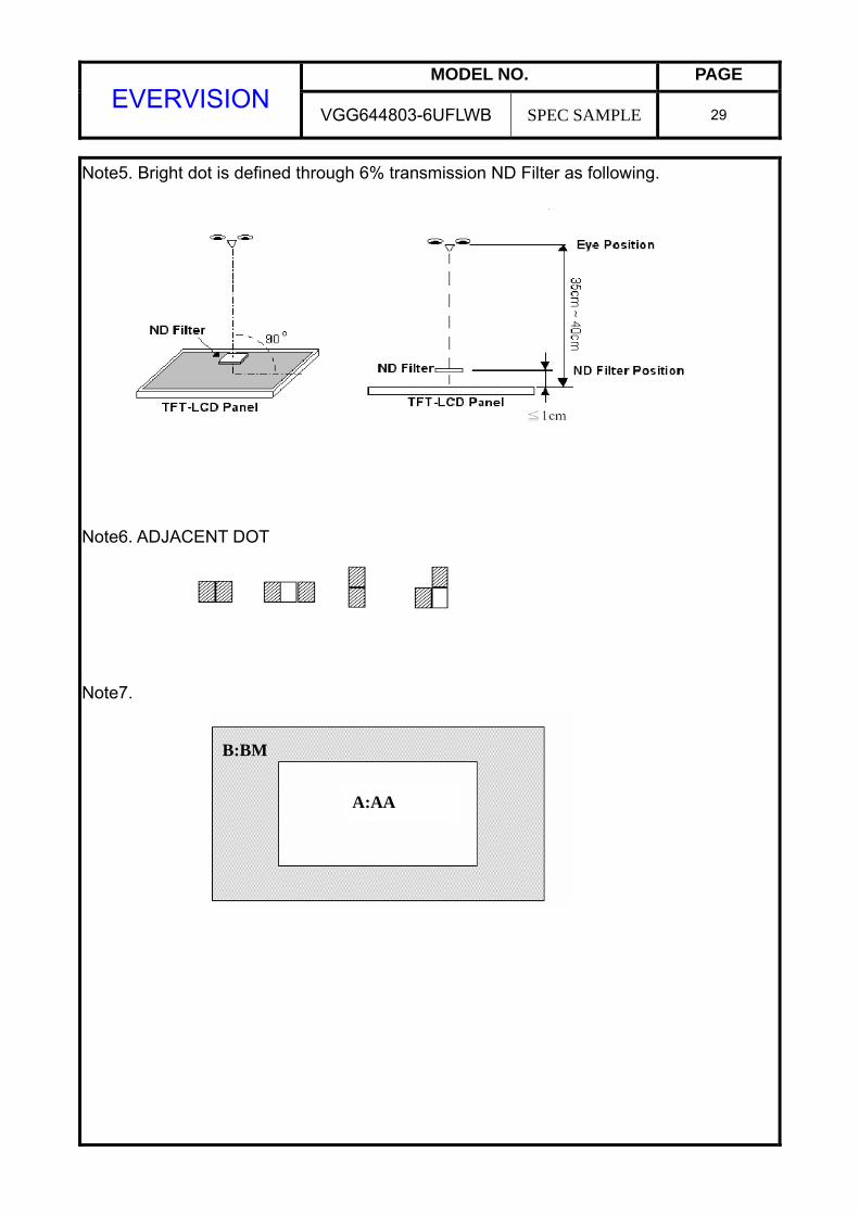
Note5. Bright dot is defined through 6% transmission ND Filter as following.
Note6. ADJACENT DOT
Note7.
B:BM
A:AA
MODEL NO. PAGE EVERVISION
VGG644803-6UFLWB SPEC SAMPLE 30
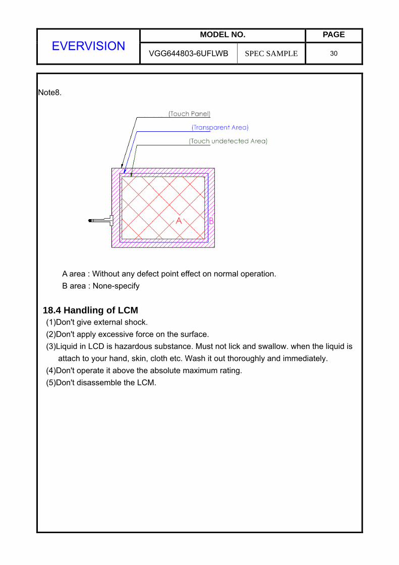
Note8.
A area : Without any defect point effect on normal operation.
B area : None-specify 18.4 Handling of LCM (1)Don't give external shock. (2)Don't apply excessive force on the surface. (3)Liquid in LCD is hazardous substance. Must not lick and swallow. when the liquid is
attach to your hand, skin, cloth etc. Wash it out thoroughly and immediately. (4)Don't operate it above the absolute maximum rating. (5)Don't disassemble the LCM.