Embed Size (px)
Citation preview
STEEL CONSTRUCTIONTODAY & TOMORROW http://www.jisf.or.jp/en/activity/sctt/index.html
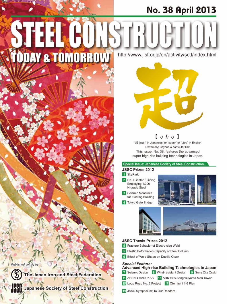
No. 38 April 2013
Seismic Design7 Sony City Osaki9ABENO HARUKAS11 ARK Hills Sengokuyama Mori Tower13Loop Road No. 2 Project15 Otemachi 1-6 Plan17
JSSC Symposium; To Our Readers19
Wind-resistant Design8
Special Feature: Advanced High-rise Building Technologies in Japan
Fracture Behavior of Electro-slag Weld5
Effect of Weld Shape on Ductile Crack6Plastic Deformation Capacity of Steel Column5
JSSC Thesis Prizes 2012
SkyPark1
Seismic Measures for Existing Building
3
Tokyo Gate Bridge4
R&D Center Building Employing 1,000 N-grade Steel
2
JSSC Prizes 2012Special Issue: Japanese Society of Steel Construction...
【 c h o 】
This issue, No. 38, features the advancedsuper high-rise building technologies in Japan.
“超 (cho)” in Japanese, or “super” or “ultra” in EnglishExtremely; Beyond a particular limit
Published Jointly by
The Japan Iron and Steel Federation
Japanese Society of Steel Construction
JSSC Prizes 2012
Steel Construction Today & Tomorrow April 20131
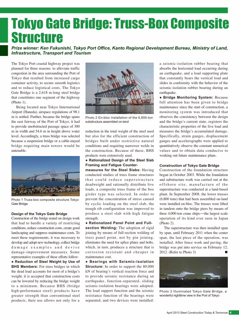
Safety MeasuresBecause the construction work for SkyPark routinely took place at heights surpassing 200 m as well as ground with other trades, unprecedented care was taken to secure maximum worker safety. Practically speaking, utmost efforts were thoroughly and repeatedly made to spread over a large working group, including 450 workers and 70 staff during the busiest period, that all workers and staff wear a full harness to prevent falling and carry lanyards to prevent the dropping of tools. (Refer to Photo 4) ◆ ◆ ◆
A noteworthy accomplishment in the construction of SkyPark is the completion of such a huge project, involving difficult cons t ruc t ion work , wi thout se r ious accidents over one million of working hours of labor. This is largely attributable to the united and highly vigorous effort by local enterprise staff, locally recruited engineers and the Japanese staff, efforts that transcended culture and language, to successfully complete the project. ■
Steel structural members were fabricated by Yongnam Engineering & Construction, a local fabricator, and transported to the construction site. In erecting the steel-frame structures on Towers 1 and 2, the structural members were lifted one by one using the tower crane to place them at the specified positions. (Refer to Photos 2 and 3) Structural members for the box girder bridge on Tower 3, the two tower-connecting
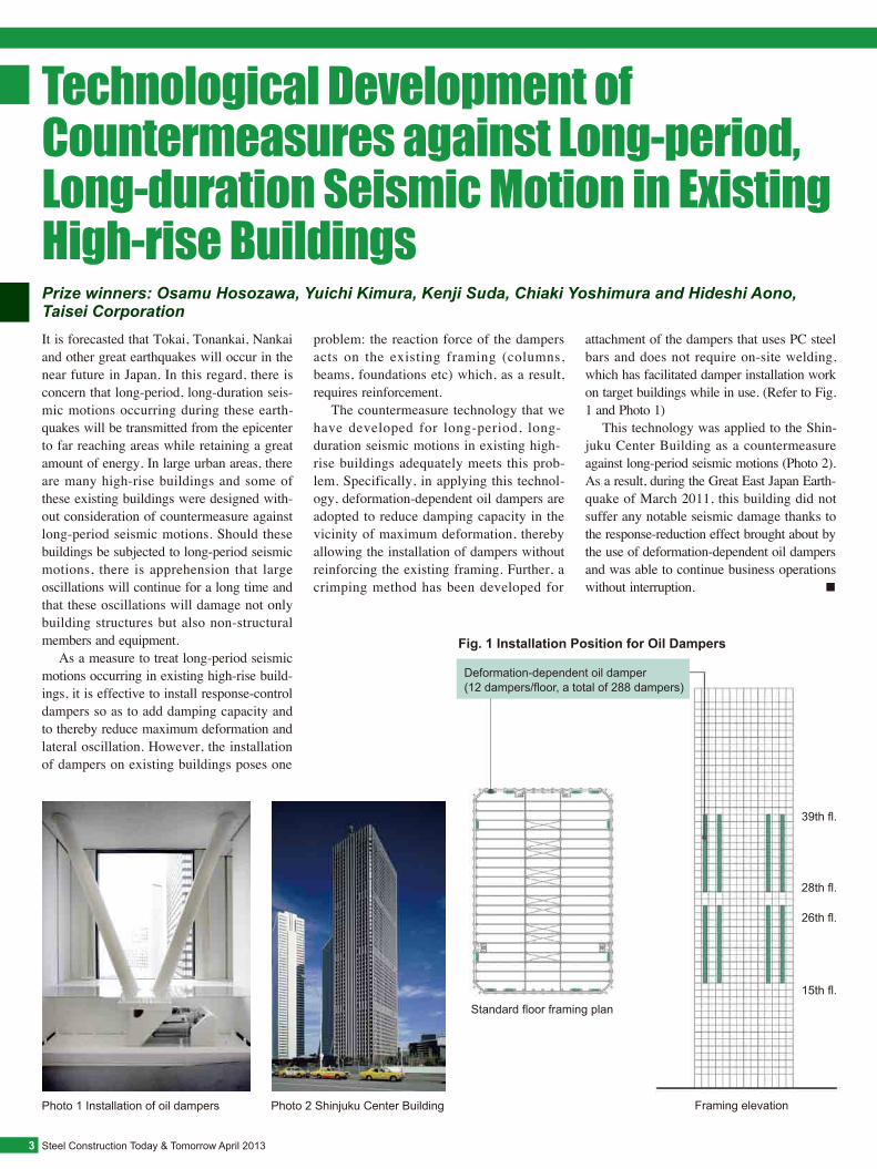
bridges and the cantilevered structure on Tower 3 were pre-assembled into large segments at the ground level in the side of the tower and lifted by means of a heavy-duty strand jack assembled on a gantry frame installed atop the tower. The large segments thus assembled numbered 3 each for the main girders of the two tower-connecting bridges, 2 for the two main girders of the box girder on Tower 3, and 6 for cantilevered structure. A total of 14 large segments, weighing 4,000 tons in total, were lifted and erected during the three months from October 1, 2009 to December 29, 2009. The segments were lifted to the target height of 200 m. Each segment was lifted at a rate of 15 m/hour, over a 15-hour period.
SkyPark: A Huge Rooftop, Steel Structure Spanning Three High-rise TowersPrize winner: Yasuhisa Miwa, JFE Engineering Corporation
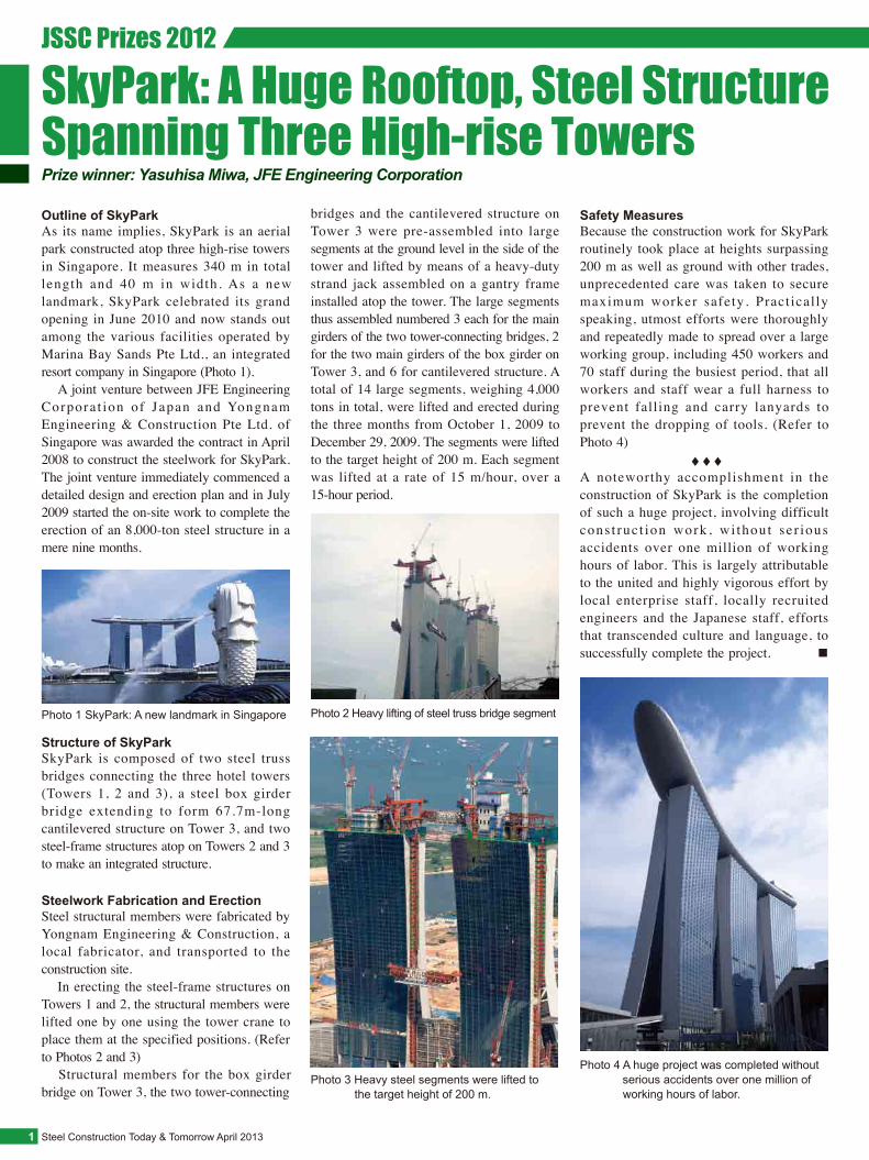
Outline of SkyParkAs its name implies, SkyPark is an aerial park constructed atop three high-rise towers in Singapore. It measures 340 m in total length and 40 m in width. As a new landmark, SkyPark celebrated its grand opening in June 2010 and now stands out among the various facilities operated by Marina Bay Sands Pte Ltd., an integrated resort company in Singapore (Photo 1). A joint venture between JFE Engineering Corpora t ion of Japan and Yongnam Engineering & Construction Pte Ltd. of Singapore was awarded the contract in April 2008 to construct the steelwork for SkyPark. The joint venture immediately commenced a detailed design and erection plan and in July 2009 started the on-site work to complete the erection of an 8,000-ton steel structure in a mere nine months.
Steelwork Fabrication and Erection
Structure of SkyParkSkyPark is composed of two steel truss bridges connecting the three hotel towers (Towers 1, 2 and 3), a steel box girder bridge extending to form 67.7m-long cantilevered structure on Tower 3, and two steel-frame structures atop on Towers 2 and 3 to make an integrated structure.
Photo 4 A huge project was completed without serious accidents over one million of working hours of labor.
Photo 1 SkyPark: A new landmark in Singapore
Photo 3 Heavy steel segments were lifted to the target height of 200 m.
Photo 2 Heavy lifting of steel truss bridge segment
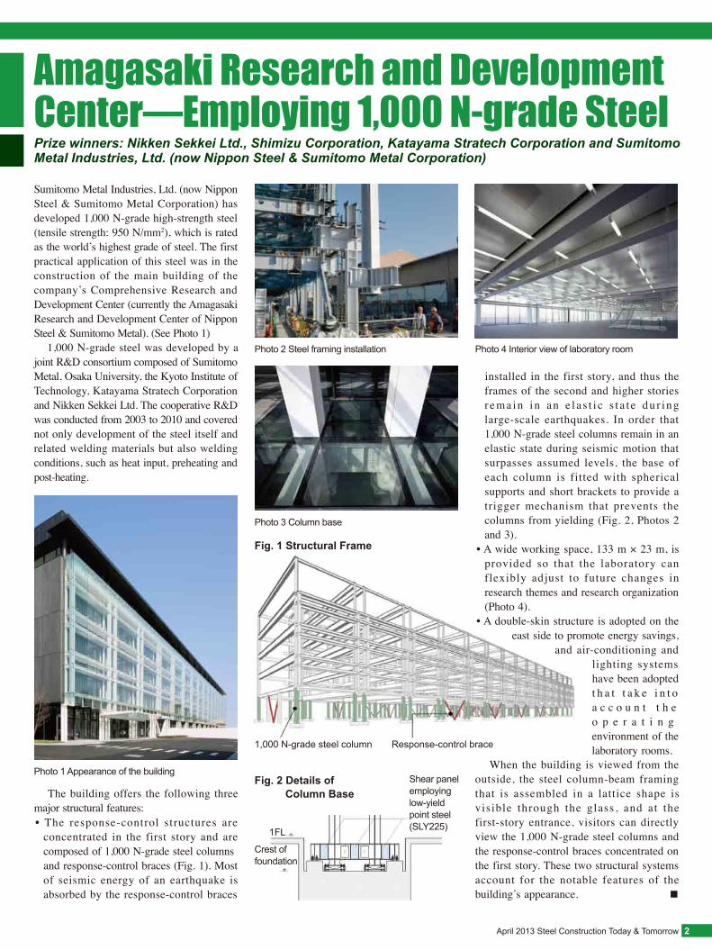
Fig. 1 Structural Frame
Fig. 2 Details of Column Base
April 2013 Steel Construction Today & Tomorrow 2
Amagasaki Research and Development Center—Employing 1,000 N-grade SteelPrize winners: Nikken Sekkei Ltd., Shimizu Corporation, Katayama Stratech Corporation and Sumitomo Metal Industries, Ltd. (now Nippon Steel & Sumitomo Metal Corporation)
Sumitomo Metal Industries, Ltd. (now Nippon Steel & Sumitomo Metal Corporation) has developed 1,000 N-grade high-strength steel (tensile strength: 950 N/mm2), which is rated as the world’s highest grade of steel. The first practical application of this steel was in the construction of the main building of the company’s Comprehensive Research and Development Center (currently the Amagasaki Research and Development Center of Nippon Steel & Sumitomo Metal). (See Photo 1) 1,000 N-grade steel was developed by a joint R&D consortium composed of Sumitomo Metal, Osaka University, the Kyoto Institute of Technology, Katayama Stratech Corporation and Nikken Sekkei Ltd. The cooperative R&D was conducted from 2003 to 2010 and covered not only development of the steel itself and related welding materials but also welding conditions, such as heat input, preheating and post-heating.
The building offers the following three major structural features:
When the building is viewed from the outside, the steel column-beam framing that is assembled in a lattice shape is visible through the glass, and at the first-story entrance, visitors can directly view the 1,000 N-grade steel columns and the response-control braces concentrated on the first story. These two structural systems account for the notable features of the building’s appearance. ■
• The response-control structures are concentrated in the first story and are composed of 1,000 N-grade steel columns and response-control braces (Fig. 1). Most of seismic energy of an earthquake is absorbed by the response-control braces
Photo 1 Appearance of the building
Photo 4 Interior view of laboratory room
Photo 3 Column base
Photo 2 Steel framing installation
1FL
Shear panel employing low-yield point steel (SLY225)
Crest of foundation
1,000 N-grade steel column Response-control brace
installed in the first story, and thus the frames of the second and higher stories r ema in in an e l a s t i c s t a t e du r ing large-scale earthquakes. In order that 1,000 N-grade steel columns remain in an elastic state during seismic motion that surpasses assumed levels, the base of each column is fitted with spherical supports and short brackets to provide a trigger mechanism that prevents the columns from yielding (Fig. 2, Photos 2 and 3).
• A wide working space, 133 m × 23 m, is provided so that the laboratory can flexibly adjust to future changes in research themes and research organization (Photo 4).
• A double-skin structure is adopted on the east side to promote energy savings,
and air-conditioning and lighting systems have been adopted t h a t t a k e i n t o a c c o u n t t h e o p e r a t i n g environment of the laboratory rooms.
Steel Construction Today & Tomorrow April 20133
Technological Development of Countermeasures against Long-period, Long-duration Seismic Motion in Existing High-rise BuildingsIt is forecasted that Tokai, Tonankai, Nankai and other great earthquakes will occur in the near future in Japan. In this regard, there is concern that long-period, long-duration seis-mic motions occurring during these earth-quakes will be transmitted from the epicenter to far reaching areas while retaining a great amount of energy. In large urban areas, there are many high-rise buildings and some of these existing buildings were designed with-out consideration of countermeasure against long-period seismic motions. Should these buildings be subjected to long-period seismic motions, there is apprehension that large oscillations will continue for a long time and that these oscillations will damage not only building structures but also non-structural members and equipment. As a measure to treat long-period seismic motions occurring in existing high-rise build-ings, it is effective to install response-control dampers so as to add damping capacity and to thereby reduce maximum deformation and lateral oscillation. However, the installation of dampers on existing buildings poses one
problem: the reaction force of the dampers acts on the existing framing (columns, beams, foundations etc) which, as a result, requires reinforcement. The countermeasure technology that we have developed for long-period, long-duration seismic motions in existing high-rise buildings adequately meets this prob-lem. Specifically, in applying this technol-ogy, deformation-dependent oil dampers are adopted to reduce damping capacity in the vicinity of maximum deformation, thereby allowing the installation of dampers without reinforcing the existing framing. Further, a crimping method has been developed for
Photo 1 Installation of oil dampers Photo 2 Shinjuku Center Building
Fig. 1 Installation Position for Oil Dampers
39th fl.
28th fl.
26th fl.
15th fl.Standard floor framing plan
Framing elevation
attachment of the dampers that uses PC steel bars and does not require on-site welding, which has facilitated damper installation work on target buildings while in use. (Refer to Fig. 1 and Photo 1) This technology was applied to the Shin-juku Center Building as a countermeasure against long-period seismic motions (Photo 2). As a result, during the Great East Japan Earth-quake of March 2011, this building did not suffer any notable seismic damage thanks to the response-reduction effect brought about by the use of deformation-dependent oil dampers and was able to continue business operations without interruption. ■
Deformation-dependent oil damper(12 dampers/floor, a total of 288 dampers)
Prize winners: Osamu Hosozawa, Yuichi Kimura, Kenji Suda, Chiaki Yoshimura and Hideshi Aono, Taisei Corporation
April 2013 Steel Construction Today & Tomorrow 4
Tokyo Gate Bridge: Truss-Box Composite StructurePrize winner: Ken Fukunishi, Tokyo Port Office, Kanto Regional Development Bureau, Ministry of Land, Infrastructure, Transport and Tourism
The Tokyo Port coastal highway project was planned for three reasons: to alleviate traffic congestion in the area surrounding the Port of Tokyo that resulted from increased cargo container activity, to secure smooth logistics and to reduce logistical costs. The Tokyo Gate Bridge is a 2,618 m-long steel bridge that constitutes one segment of the highway (Photo 1). Being located near Tokyo International Airport (Haneda), airspace regulations of 98.1 m is settled. Further, because the bridge spans the east fairway of the Port of Tokyo, it had to provide unobstructed passage space of 300 m in width and 54.6 m in height above water level. Accordingly, a truss bridge was selected because a suspension bridge or a cable-stayed bridge requiring main towers would be untenable.
Photo 1 Truss-box composite structure Tokyo Gate Bridge
Photo 2 En-bloc installation of the 6,800-ton substructure assembled on-land
Photo 3 Illuminated Tokyo Gate Bridge, a wonderful nighttime view in the Port of Tokyo
Design of the Tokyo Gate BridgeConstruction of the bridge rested on design work that had to hurdle a variety of restricting conditions, reduce construction costs, create good landscaping and suppress maintenance costs. To meet these requirements, it was necessary to develop and adopt new technology, collect bridge d a m a g e e x a m p l e s a n d d e v i s e damage-improvement measures. Some representative examples of these efforts follow:● Reduction of Steel Weight by Use of BHS Members: For truss bridges in which the dead load accounts for most of a bridge’s weight, it is accepted that construction costs can be lowered by reducing the bridge weight to a minimum. Because BHS (bridge high-performance steel) products have greater strength than conventional steel products, their use allows not only for a
● Rationalized Design of the Steel Slab Framing and Fatigue Counter-measures for the Steel Slabs: Having conducted studies of truss frame structures t h a t c o u l d r e d u c e s u p e r s t r u c t u r e deadweight and rationally distribute live loads, a composite truss frame of the box girder type was selected. In order to prevent the concentration of stress caused by cyclic loading on the steel slab, the trough rib configuration was improved to produce a steel slab with high fatigue strength.● Rationalized Panel Point and Full-section Welding: The adoption of rigid joining by means of full-section welding of truss panel point, not by pin joining, eliminates the need for splice plates and bolts, which, in turn, produces a structure that is co r ro s ion r e s i s t an t and cheape r i n maintenance cost. ● Bearings with Seismic-isolation Structure: In order to support the 80,000 kN of bearing’s vertical reaction force and to provide seismic resistance during an earthquake, function-separated, sliding seismic-isolation bearings were adopted. The load support function and the seismic resistance function of the bearings were separated, and two devices were installed:
● Bridge Monitoring System: Because full attention has been given to bridge maintenance since the start of construction, a monitoring system was introduced that observes the consistency between the design and the bridge’s current state, registers the characteristic properties of the live load and measures the bridge’s accumulated damage. Specifically, strain gauges, displacement gauges and accelerographs were applied to quantitatively observe the constant numerical values and to obtain data conducive to working out future maintenance plans.
Construction of Tokyo Gate BridgeConstruction of the foundation structure began in October 2003. While the foundation and substructure work was carried out at the o f f s h o r e s i t e , m a n u f a c t u r e o f t h e superstructure was conducted at a land-based plant. In September 2008, the lower trusses (6,800 tons) that had been assembled on-land were installed en-bloc. The trusses were lifted in tandem onto the bridge piers by means of three 4,000-ton crane ships-the largest scale operation of its kind ever seen in Japan (Photo 2). The superstructure was then installed span by span, until February 2011 when the center span, the last piece of the operation, was installed. After fence work and paving, the bridge was put into service on February 12, 2012. (Refer to Photo 3) ■
reduction in the total weight of the steel used but also for the efficient construction of bridges built under restrictive natural conditions and requiring narrower welds in the construction. Because of these, BHS products were extensively used.
a seismic-isolation rubber bearing that absorbs the horizontal load occurring during an earthquake, and a load supporting plate that constantly bears the vertical load and slides in conformity with the behavior of the seismic-isolation rubber bearing during an earthquake.
JSSC Thesis Prizes 2012
Steel Construction Today & Tomorrow April 20135
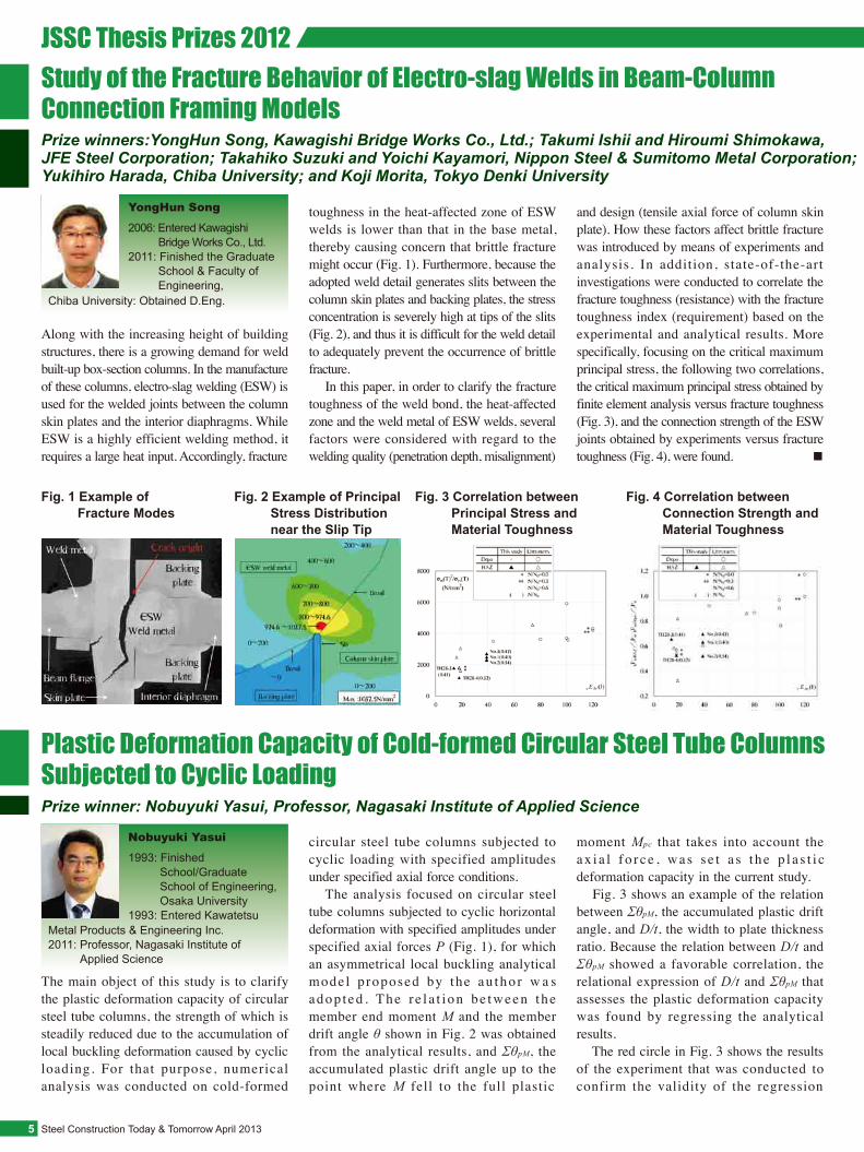
Study of the Fracture Behavior of Electro-slag Welds in Beam-Column Connection Framing ModelsPrize winners:YongHun Song, Kawagishi Bridge Works Co., Ltd.; Takumi Ishii and Hiroumi Shimokawa, JFE Steel Corporation; Takahiko Suzuki and Yoichi Kayamori, Nippon Steel & Sumitomo Metal Corporation; Yukihiro Harada, Chiba University; and Koji Morita, Tokyo Denki University
Plastic Deformation Capacity of Cold-formed Circular Steel Tube Columns Subjected to Cyclic LoadingPrize winner: Nobuyuki Yasui, Professor, Nagasaki Institute of Applied Science
Along with the increasing height of building structures, there is a growing demand for weld built-up box-section columns. In the manufacture of these columns, electro-slag welding (ESW) is used for the welded joints between the column skin plates and the interior diaphragms. While ESW is a highly efficient welding method, it requires a large heat input. Accordingly, fracture
toughness in the heat-affected zone of ESW welds is lower than that in the base metal, thereby causing concern that brittle fracture might occur (Fig. 1). Furthermore, because the adopted weld detail generates slits between the column skin plates and backing plates, the stress concentration is severely high at tips of the slits (Fig. 2), and thus it is difficult for the weld detail to adequately prevent the occurrence of brittle fracture. In this paper, in order to clarify the fracture toughness of the weld bond, the heat-affected zone and the weld metal of ESW welds, several factors were considered with regard to the welding quality (penetration depth, misalignment)
Fig. 1 Example of Fracture Modes
Fig. 2 Example of Principal Stress Distribution near the Slip Tip
Fig. 3 Correlation between Principal Stress and Material Toughness
Fig. 4 Correlation between Connection Strength and Material Toughness
The main object of this study is to clarify the plastic deformation capacity of circular steel tube columns, the strength of which is steadily reduced due to the accumulation of local buckling deformation caused by cyclic loading. For that purpose, numerical analysis was conducted on cold-formed
circular steel tube columns subjected to cyclic loading with specified amplitudes under specified axial force conditions. The analysis focused on circular steel tube columns subjected to cyclic horizontal deformation with specified amplitudes under specified axial forces P (Fig. 1), for which an asymmetrical local buckling analytical mode l p roposed by the au tho r w a s adop t ed . The r e l a t i on be tween t he member end moment M and the member drift angle θ shown in Fig. 2 was obtained from the analytical results, and ΣθpM, the accumulated plastic drift angle up to the point where M fell to the full plastic
2006: Entered Kawagishi Bridge Works Co., Ltd.
2011: Finished the Graduate School & Faculty of Engineering,
YongHun Song
1993: Finished School/Graduate School of Engineering, Osaka University
1993: Entered Kawatetsu
Nobuyuki Yasui
and design (tensile axial force of column skin plate). How these factors affect brittle fracture was introduced by means of experiments and analysis. In addition, state-of-the-art investigations were conducted to correlate the fracture toughness (resistance) with the fracture toughness index (requirement) based on the experimental and analytical results. More specifically, focusing on the critical maximum principal stress, the following two correlations, the critical maximum principal stress obtained by finite element analysis versus fracture toughness (Fig. 3), and the connection strength of the ESW joints obtained by experiments versus fracture toughness (Fig. 4), were found. ■
moment Mpc that takes into account the a x i a l f o r c e , w a s s e t a s t h e p l a s t i c deformation capacity in the current study. Fig. 3 shows an example of the relation between ΣθpM, the accumulated plastic drift angle, and D/t, the width to plate thickness ratio. Because the relation between D/t and ΣθpM showed a favorable correlation, the relational expression of D/t and ΣθpM that assesses the plastic deformation capacity was found by regressing the analytical results. The red circle in Fig. 3 shows the results of the experiment that was conducted to confirm the validity of the regression
Chiba University: Obtained D.Eng.
Metal Products & Engineering Inc.2011: Professor, Nagasaki Institute of Applied Science
April 2013 Steel Construction Today & Tomorrow 6
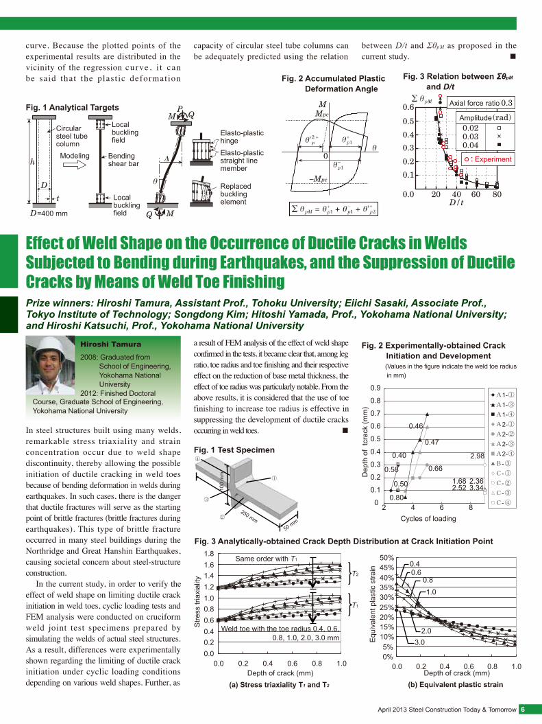
Effect of Weld Shape on the Occurrence of Ductile Cracks in Welds Subjected to Bending during Earthquakes, and the Suppression of Ductile Cracks by Means of Weld Toe FinishingPrize winners: Hiroshi Tamura, Assistant Prof., Tohoku University; Eiichi Sasaki, Associate Prof., Tokyo Institute of Technology; Songdong Kim; Hitoshi Yamada, Prof., Yokohama National University; and Hiroshi Katsuchi, Prof., Yokohama National University
In steel structures built using many welds, remarkable stress triaxiality and strain concentration occur due to weld shape discontinuity, thereby allowing the possible initiation of ductile cracking in weld toes because of bending deformation in welds during earthquakes. In such cases, there is the danger that ductile fractures will serve as the starting point of brittle fractures (brittle fractures during earthquakes). This type of brittle fracture occurred in many steel buildings during the Northridge and Great Hanshin Earthquakes, causing societal concern about steel-structure construction. In the current study, in order to verify the effect of weld shape on limiting ductile crack initiation in weld toes, cyclic loading tests and FEM analysis were conducted on cruciform weld joint test specimens prepared by simulating the welds of actual steel structures. As a result, differences were experimentally shown regarding the limiting of ductile crack initiation under cyclic loading conditions depending on various weld shapes. Further, as
a result of FEM analysis of the effect of weld shape confirmed in the tests, it became clear that, among leg ratio, toe radius and toe finishing and their respective effect on the reduction of base metal thickness, the effect of toe radius was particularly notable. From the above results, it is considered that the use of toe finishing to increase toe radius is effective in suppressing the development of ductile cracks occurring in weld toes. ■
250 mm 50 mm
100
mm
Cycles of loading
0
0.1
0.2
0.3
0.4
0.5
0.6
0.7
0.8
0.9
2 4 6 8
1-1-1-2-2-2-2------
Dep
th o
f tc
rack
(mm
)
0.58
0.40
0.50
0.80
0.46
0.47
0.66
2.98
2.36 2.52 3.34 1.68
Fig. 2 Experimentally-obtained Crack Initiation and Development
(Values in the figure indicate the weld toe radius in mm)
Fig. 3 Analytically-obtained Crack Depth Distribution at Crack Initiation Point
0.00.20.40.60.81.01.21.41.61.8
0.0 0.2 0.4 0.6 0.8 1.0
Stre
ss tr
iaxi
ality
Depth of crack (mm)
Weld toe with the toe radius 0.4, 0.6,0.8, 1.0, 2.0, 3.0 mm
Same order with T1
(a) Stress triaxiality T1 and T2
0.4 0.6
1.0
2.0 3.0
0.8
0%5%
10%15%20%25%30%35%40%45%50%
0.0 0.2 0.4 0.6 0.8 1.0Depth of crack (mm)
(b) Equivalent plastic strain
Equ
ival
ent p
last
ic s
train
T1
T2
2008: Graduated from School of Engineering, Yokohama National University
2012: Finished Doctoral
Hiroshi Tamura
Elasto-plastic hingeElasto-plastic straight line member
Replaced buckling element
Fig. 1 Analytical Targets
Fig. 2 Accumulated Plastic Deformation Angle
Experiment
Amplitude
Axial force ratio
Fig. 3 Relation between ΣθpM and D/t
Circular steel tube columnModeling
=400 mm
Local buckling field
Bending shear bar
Local buckling field
curve. Because the plotted points of the experimental results are distributed in the vicinity of the regression curve , i t can be said that the plast ic deformation
capacity of circular steel tube columns can be adequately predicted using the relation
Course, Graduate School of Engineering,Yokohama National University
between D/t and ΣθpM as proposed in the current study. ■
Fig. 1 Test Specimen
Steel Construction Today & Tomorrow April 20137
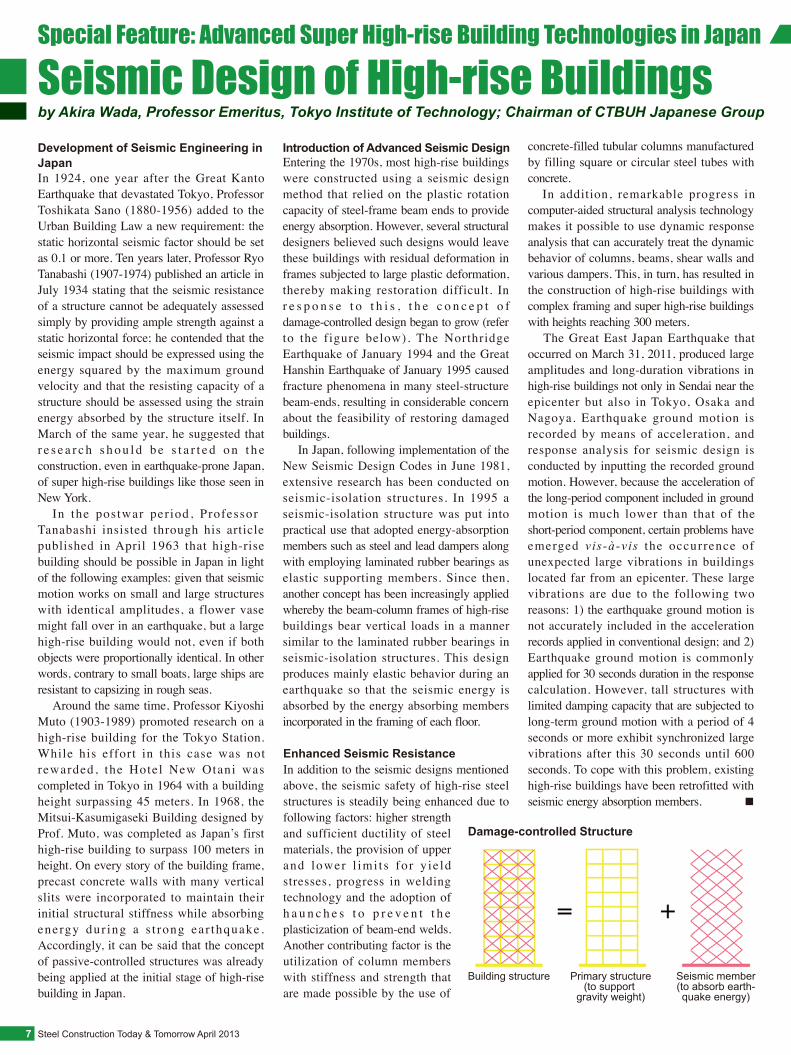
Seismic Design of High-rise Buildingsby Akira Wada, Professor Emeritus, Tokyo Institute of Technology; Chairman of CTBUH Japanese Group
Development of Seismic Engineering in JapanIn 1924, one year after the Great Kanto Earthquake that devastated Tokyo, Professor Toshikata Sano (1880-1956) added to the Urban Building Law a new requirement: the static horizontal seismic factor should be set as 0.1 or more. Ten years later, Professor Ryo Tanabashi (1907-1974) published an article in July 1934 stating that the seismic resistance of a structure cannot be adequately assessed simply by providing ample strength against a static horizontal force; he contended that the seismic impact should be expressed using the energy squared by the maximum ground velocity and that the resisting capacity of a structure should be assessed using the strain energy absorbed by the structure itself. In March of the same year, he suggested that r e s e a r c h s h o u l d b e s t a r t e d o n t h e construction, even in earthquake-prone Japan, of super high-rise buildings like those seen in New York. In the postwar per iod, ProfessorTanabashi insisted through his article published in April 1963 that high-rise building should be possible in Japan in light of the following examples: given that seismic motion works on small and large structures with identical amplitudes, a flower vase might fall over in an earthquake, but a large high-rise building would not, even if both objects were proportionally identical. In other words, contrary to small boats, large ships are resistant to capsizing in rough seas. Around the same time, Professor Kiyoshi Muto (1903-1989) promoted research on a high-rise building for the Tokyo Station. While his effort in this case was not rewarded, the Hotel New Otani was completed in Tokyo in 1964 with a building height surpassing 45 meters. In 1968, the Mitsui-Kasumigaseki Building designed by Prof. Muto, was completed as Japan’s first high-rise building to surpass 100 meters in height. On every story of the building frame, precast concrete walls with many vertical slits were incorporated to maintain their initial structural stiffness while absorbing energy dur ing a s t rong ear thquake . Accordingly, it can be said that the concept of passive-controlled structures was already being applied at the initial stage of high-rise building in Japan.
Introduction of Advanced Seismic DesignEntering the 1970s, most high-rise buildings were constructed using a seismic design method that relied on the plastic rotation capacity of steel-frame beam ends to provide energy absorption. However, several structural designers believed such designs would leave these buildings with residual deformation in frames subjected to large plastic deformation, thereby making restoration difficult. In r e s p o n s e t o t h i s , t h e c o n c e p t o f damage-controlled design began to grow (refer to the figure below). The Northridge Earthquake of January 1994 and the Great Hanshin Earthquake of January 1995 caused fracture phenomena in many steel-structure beam-ends, resulting in considerable concern about the feasibility of restoring damaged buildings. In Japan, following implementation of the New Seismic Design Codes in June 1981, extensive research has been conducted on seismic-isolation structures. In 1995 a seismic-isolation structure was put into practical use that adopted energy-absorption members such as steel and lead dampers along with employing laminated rubber bearings as elastic supporting members. Since then, another concept has been increasingly applied whereby the beam-column frames of high-rise buildings bear vertical loads in a manner similar to the laminated rubber bearings in seismic-isolation structures. This design produces mainly elastic behavior during an earthquake so that the seismic energy is absorbed by the energy absorbing members incorporated in the framing of each floor.
Enhanced Seismic ResistanceIn addition to the seismic designs mentioned above, the seismic safety of high-rise steel structures is steadily being enhanced due to following factors: higher strength and sufficient ductility of steel materials, the provision of upper and lower l imi t s for y ie ld stresses, progress in welding technology and the adoption of h a u n c h e s t o p r e v e n t t h e plasticization of beam-end welds. Another contributing factor is the utilization of column members with stiffness and strength that are made possible by the use of
concrete-filled tubular columns manufactured by filling square or circular steel tubes with concrete. In addition, remarkable progress in computer-aided structural analysis technology makes it possible to use dynamic response analysis that can accurately treat the dynamic behavior of columns, beams, shear walls and various dampers. This, in turn, has resulted in the construction of high-rise buildings with complex framing and super high-rise buildings with heights reaching 300 meters. The Great East Japan Earthquake that occurred on March 31, 2011, produced large amplitudes and long-duration vibrations in high-rise buildings not only in Sendai near the epicenter but also in Tokyo, Osaka and Nagoya. Earthquake ground motion is recorded by means of acceleration, and response analysis for seismic design is conducted by inputting the recorded ground motion. However, because the acceleration of the long-period component included in ground motion is much lower than that of the short-period component, certain problems have emerged vis-à-vis the occurrence of unexpected large vibrations in buildings located far from an epicenter. These large vibrations are due to the following two reasons: 1) the earthquake ground motion is not accurately included in the acceleration records applied in conventional design; and 2) Earthquake ground motion is commonly applied for 30 seconds duration in the response calculation. However, tall structures with limited damping capacity that are subjected to long-term ground motion with a period of 4 seconds or more exhibit synchronized large vibrations after this 30 seconds until 600 seconds. To cope with this problem, existing high-rise buildings have been retrofitted with seismic energy absorption members. ■
Damage-controlled Structure
Building structure Primary structure(to support
gravity weight)
Seismic member(to absorb earth-quake energy)
Special Feature: Advanced Super High-rise Building Technologies in Japan
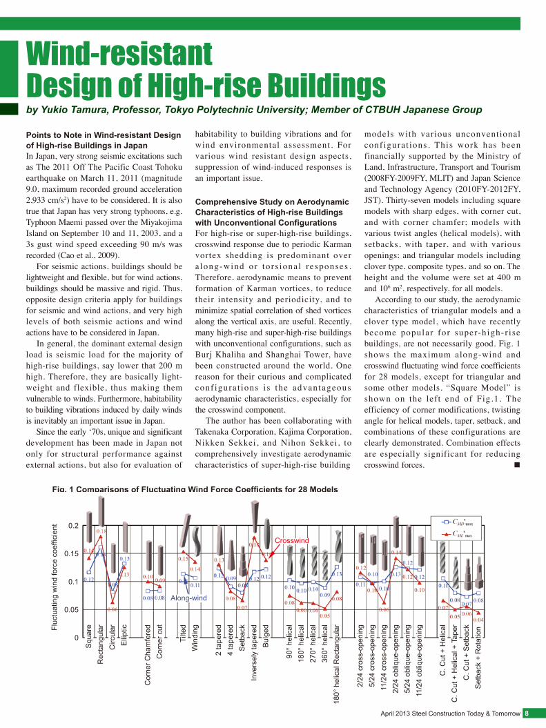
Fig. 1 Comparisons of Fluctuating Wind Force Coefficients for 28 Models
Fluc
tuat
ing
win
d fo
rce
coef
ficie
nt
Squ
are
Rec
tang
ular
Circ
ular
Elli
ptic
Cor
ner C
ham
fere
dC
orne
r cut
Tilte
dW
indi
ng
2 ta
pere
d4
tape
red
Set
back
Inve
rsel
y ta
pere
dB
ulge
d
90°
helic
al18
0° h
elic
al27
0° h
elic
al36
0° h
elic
al18
0° h
elic
al R
ecta
ngul
ar
2/24
cro
ss-o
peni
ng5/
24 c
ross
-ope
ning
11/2
4 cr
oss-
open
ing
2/24
obl
ique
-ope
ning
5/24
obl
ique
-ope
ning
11/2
4 ob
lique
-ope
ning
C. C
ut +
Hel
ical
C. C
ut +
Hel
ical
+ T
aper
C. C
ut +
Set
back
Set
back
+ R
otat
ion
0.2
0.15
0.1
0.05
0
Crosswind
Along-wind
April 2013 Steel Construction Today & Tomorrow 8
Wind-resistant Design of High-rise Buildingsby Yukio Tamura, Professor, Tokyo Polytechnic University; Member of CTBUH Japanese Group
Points to Note in Wind-resistant Design of High-rise Buildings in JapanIn Japan, very strong seismic excitations such as The 2011 Off The Pacific Coast Tohoku earthquake on March 11, 2011 (magnitude 9.0, maximum recorded ground acceleration 2,933 cm/s2) have to be considered. It is also true that Japan has very strong typhoons, e.g. Typhoon Maemi passed over the Miyakojima Island on September 10 and 11, 2003, and a 3s gust wind speed exceeding 90 m/s was recorded (Cao et al., 2009). For seismic actions, buildings should be lightweight and flexible, but for wind actions, buildings should be massive and rigid. Thus, opposite design criteria apply for buildings for seismic and wind actions, and very high levels of both seismic actions and wind actions have to be considered in Japan. In general, the dominant external design load is seismic load for the majority of high-rise buildings, say lower that 200 m high. Therefore, they are basically light- weight and flexible, thus making them vulnerable to winds. Furthermore, habitability to building vibrations induced by daily winds is inevitably an important issue in Japan. Since the early ‘70s, unique and significant development has been made in Japan not only for structural performance against external actions, but also for evaluation of
habitability to building vibrations and for wind environmental assessment. For various wind resistant design aspects, suppression of wind-induced responses is an important issue.
Comprehensive Study on Aerodynamic Characteristics of High-rise Buildings with Unconventional ConfigurationsFor high-rise or super-high-rise buildings, crosswind response due to periodic Karman vortex shedding is predominant over a long-wind o r to r s iona l r e sponses . Therefore, aerodynamic means to prevent formation of Karman vortices, to reduce their intensity and periodicity, and to minimize spatial correlation of shed vortices along the vertical axis, are useful. Recently, many high-rise and super-high-rise buildings with unconventional configurations, such as Burj Khaliha and Shanghai Tower, have been constructed around the world. One reason for their curious and complicated conf igura t ions i s the advantageous aerodynamic characteristics, especially for the crosswind component. The author has been collaborating with Takenaka Corporation, Kajima Corporation, Nikken Sekkei, and Nihon Sekkei, to comprehensively investigate aerodynamic characteristics of super-high-rise building
models with various unconventional conf igura t ions . This work has been financially supported by the Ministry of Land, Infrastructure, Transport and Tourism (2008FY-2009FY, MLIT) and Japan Science and Technology Agency (2010FY-2012FY, JST). Thirty-seven models including square models with sharp edges, with corner cut, and with corner chamfer; models with various twist angles (helical models), with setbacks, with taper, and with various openings; and triangular models including clover type, composite types, and so on. The height and the volume were set at 400 m and 106 m2, respectively, for all models. According to our study, the aerodynamic characteristics of triangular models and a clover type model, which have recently become popular for super-high-r ise buildings, are not necessarily good. Fig. 1 shows the maximum along-wind and crosswind fluctuating wind force coefficients for 28 models, except for triangular and some other models. “Square Model” is shown on the lef t end of Fig.1. The efficiency of corner modifications, twisting angle for helical models, taper, setback, and combinations of these configurations are clearly demonstrated. Combination effects are especially significant for reducing crosswind forces. ■
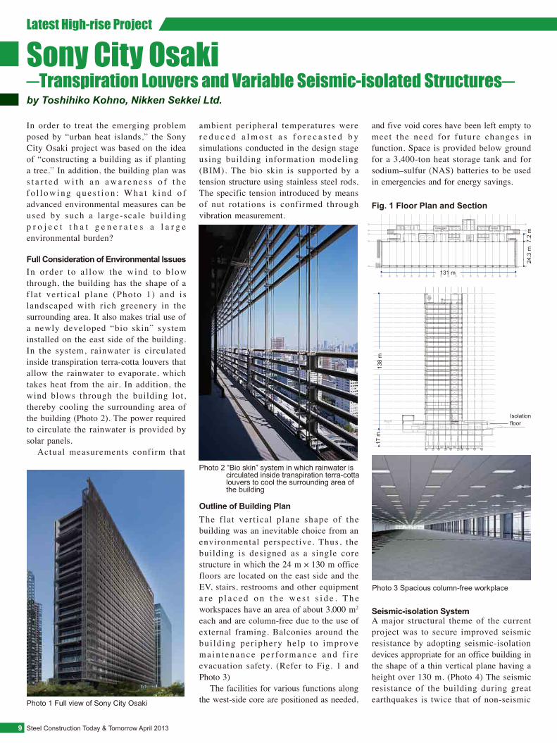
ambient peripheral temperatures were r e d u c e d a l m o s t a s f o r e c a s t e d b y simulations conducted in the design stage using building information modeling (BIM). The bio skin is supported by a tension structure using stainless steel rods. The specific tension introduced by means of nut rotations is confirmed through vibration measurement.
Fig. 1 Floor Plan and Section
Latest High-rise Project
Steel Construction Today & Tomorrow April 20139
Sony City Osaki─Transpiration Louvers and Variable Seismic-isolated Structures─by Toshihiko Kohno, Nikken Sekkei Ltd.
In order to treat the emerging problem posed by “urban heat islands,” the Sony City Osaki project was based on the idea of “constructing a building as if planting a tree.” In addition, the building plan was s t a r t e d w i t h a n a w a r e n e s s o f t h e f o l l o w i n g q u e s t i o n : W h a t k i n d o f advanced environmental measures can be used by such a large-scale bui lding p r o j e c t t h a t g e n e r a t e s a l a r g e environmental burden?
In order to a l low the wind to b low through, the building has the shape of a f la t ver t ica l p lane (Photo 1) and i s landscaped with rich greenery in the surrounding area. It also makes trial use of a newly developed “bio skin” system installed on the east side of the building. In the system, rainwater is circulated inside transpiration terra-cotta louvers that allow the rainwater to evaporate, which takes heat from the air. In addition, the wind blows through the building lot, thereby cooling the surrounding area of the building (Photo 2). The power required to circulate the rainwater is provided by solar panels. Actual measurements confirm that
Outline of Building Plan
Seismic-isolation System
Photo 1 Full view of Sony City Osaki
Full Consideration of Environmental Issues
Photo 2 “Bio skin” system in which rainwater is circulated inside transpiration terra-cotta louvers to cool the surrounding area of the building
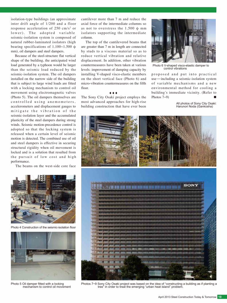
The f la t ver t ical plane shape of the building was an inevitable choice from an environmental perspective. Thus, the building is designed as a single core structure in which the 24 m × 130 m office floors are located on the east side and the EV, stairs, restrooms and other equipment a r e p l a c e d o n t h e w e s t s i d e . T h e workspaces have an area of about 3,000 m2 each and are column-free due to the use of external framing. Balconies around the bui ld ing per iphery he lp to improve m a i n t e n a n c e p e r f o r m a n c e a n d f i r e evacuation safety. (Refer to Fig. 1 and Photo 3) The facilities for various functions along the west-side core are positioned as needed,
A major structural theme of the current project was to secure improved seismic resistance by adopting seismic-isolation devices appropriate for an office building in the shape of a thin vertical plane having a height over 130 m. (Photo 4) The seismic resistance of the building during great earthquakes is twice that of non-seismic
Photo 3 Spacious column-free workplace
and five void cores have been left empty to meet the need for future changes in function. Space is provided below ground for a 3,400-ton heat storage tank and for sodium–sulfur (NAS) batteries to be used in emergencies and for energy savings.
131 m
24.3
m7.
2 m
138
m17
m
Isolation floor
April 2013 Steel Construction Today & Tomorrow 10
All photos of Sony City Osaki: Harunori Noda (Gankosha)
isolation-type buildings (an approximate inter drift angle of 1/200 and a floor response acceleration of 250 cm/s2 or l o w e r ) . T h e a d o p t e d v a r i a b l e seismic-isolation system is composed of natural rubber-laminated isolators (high bearing specifications of 1,100~1,500 φ mm), oil dampers and steel dampers. Because of the steel-structure flat vertical shape of the building, the anticipated wind load generated by a typhoon would be larger than the seismic load reduced by the seismic-isolation system. The oil dampers installed on the narrow side of the building that is subject to large wind loads are fitted with a locking mechanism to control oil movement using electromagnetic valves (Photo 5). The oil dampers themselves are c o n t r o l l e d u s i n g a n e m o m e t e r s , accelerometers and displacement gauges to m i t i g a t e t h e v i b r a t i o n o f t h e seismic-isolation layer and the accumulated plasticity of the steel dampers during strong winds. Seismic motion-precedence control is adopted so that the locking system is released when a certain level of seismic motion is detected. The combined use of oil and steel dampers is effective in securing structural rigidity when oil movement is locked and is a solution that resulted from t h e p u r s u i t o f l o w c o s t a n d h i g h performance. The beams on the west-side core face
Photo 4 Construction of the seismic-isolation floor
Photo 6 V-shaped visco-elastic damper to control vibrations
cantilever more than 7 m and reduce the axial force of the intermediate columns so as not to overstress the 1,500 φ mm isolators supporting the intermediate column. The top of the cantilevered beams that are greater than 7 m in length are connected by studs to a viscous material so as to reduce vertical vibration and relative displacement. In addition, other vibration countermeasures have been taken at various levels: improvement of damping capacity by installing V-shaped visco-elastic members on the short vertical face (Photo 6) and micro-vibration countermeasures on the fifth floor. ◆ ◆ ◆The Sony City Osaki project employs the most advanced approaches for high-rise building construction that have ever been
Photo 5 Oil damper fitted with a locking mechanism to control oil movement
Photos 7~9 Sony City Osaki project was based on the idea of “constructing a building as if planting a tree” in order to treat the emerging “urban heat island” problem.
p r o p o s e d a n d p u t i n t o p r a c t i c a l use-including a seismic-isolation system of va r i ab le mechan i sms and a new environmental method for cooling a building’s immediate vicinity. (Refer to Photos 7~9) ■
Steel Construction Today & Tomorrow April 201311
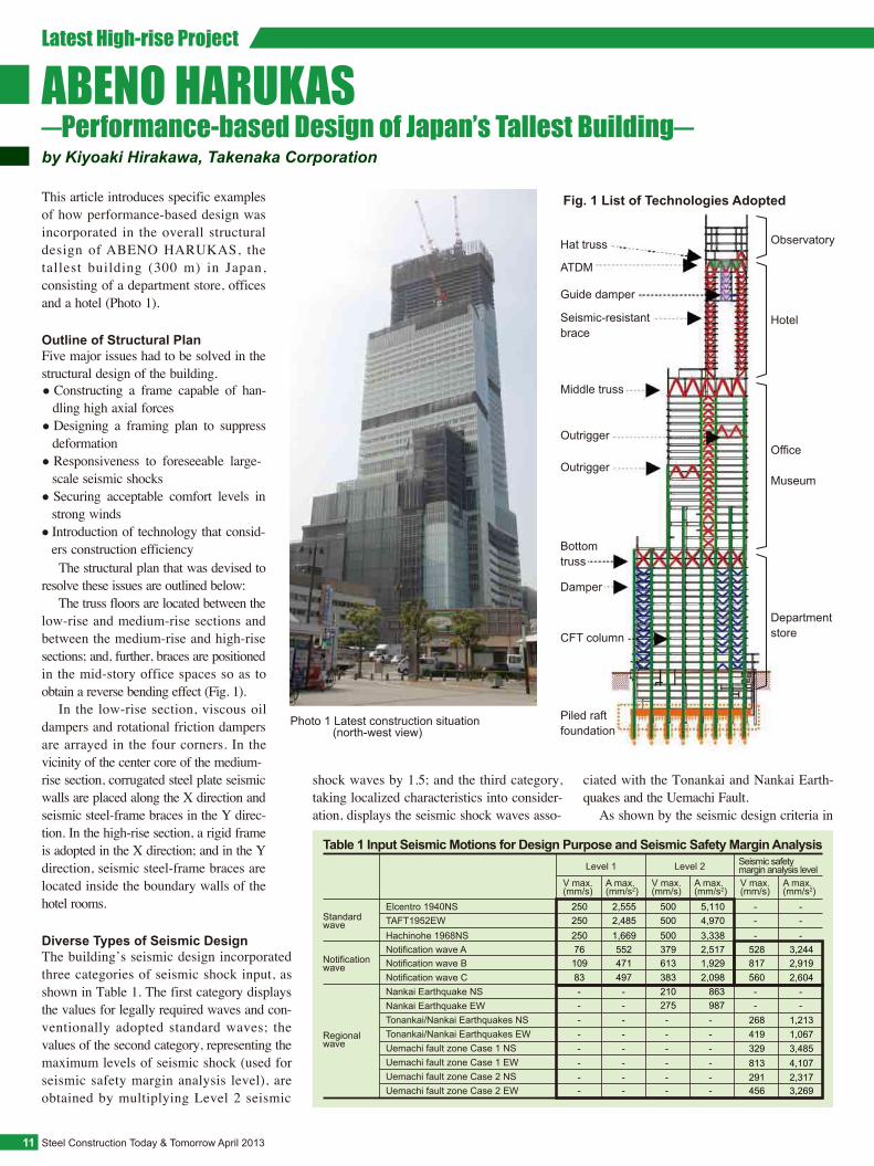
Outline of Structural PlanFive major issues had to be solved in the structural design of the building.
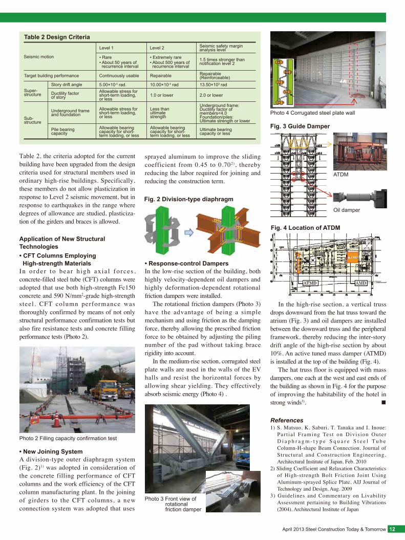
Diverse Types of Seismic DesignThe building’s seismic design incorporated three categories of seismic shock input, as shown in Table 1. The first category displays the values for legally required waves and con-ventionally adopted standard waves; the values of the second category, representing the maximum levels of seismic shock (used for seismic safety margin analysis level), are obtained by multiplying Level 2 seismic
The structural plan that was devised to resolve these issues are outlined below: The truss floors are located between the low-rise and medium-rise sections and between the medium-rise and high-rise sections; and, further, braces are positioned in the mid-story office spaces so as to obtain a reverse bending effect (Fig. 1). In the low-rise section, viscous oil dampers and rotational friction dampers are arrayed in the four corners. In the vicinity of the center core of the medium-rise section, corrugated steel plate seismic walls are placed along the X direction and seismic steel-frame braces in the Y direc-tion. In the high-rise section, a rigid frame is adopted in the X direction; and in the Y direction, seismic steel-frame braces are located inside the boundary walls of the hotel rooms.
ABENO HARUKAS─Performance-based Design of Japan’s Tallest Building─by Kiyoaki Hirakawa, Takenaka Corporation
This article introduces specific examples of how performance-based design was incorporated in the overall structural design of ABENO HARUKAS, the tallest building (300 m) in Japan, consisting of a department store, offices and a hotel (Photo 1).
Latest High-rise Project
● Constructing a frame capable of han-dling high axial forces
● Designing a framing plan to suppress deformation
● Responsiveness to foreseeable large-scale seismic shocks
● Securing acceptable comfort levels in strong winds
● Introduction of technology that consid-ers construction efficiency
shock waves by 1.5; and the third category, taking localized characteristics into consider-ation, displays the seismic shock waves asso-
Hat truss
ATDM
Guide damper
Seismic-resistant brace
Middle truss
Outrigger
Outrigger
Bottomtruss
Damper
CFT column
Piled raft foundation
Observatory
Hotel
Office
Museum
Departmentstore
Fig. 1 List of Technologies Adopted
Table 1 Input Seismic Motions for Design Purpose and Seismic Safety Margin Analysis
Notificationwave
Regionalwave
Level 1 Seismic safety margin analysis levelLevel 2
Notification wave BNotification wave C
Tonankai/Nankai Earthquakes NSTonankai/Nankai Earthquakes EWUemachi fault zone Case 1 NSUemachi fault zone Case 1 EWUemachi fault zone Case 2 NSUemachi fault zone Case 2 EW
Nankai Earthquake NSNankai Earthquake EW
Standard wave
Elcentro 1940NSTAFT1952EWHachinohe 1968NS
V max.(mm/s)
A max.(mm/s2)
V max.(mm/s)
A max.(mm/s2)
V max.(mm/s)
A max.(mm/s2)
------
--
10983
250250250
------
613383210275
500500500
817560
268419329813291456
--
---
------
--
471497
2,5552,4851,669
------
1,9292,098
863987
5,1104,9703,338
Notification wave A 76 379 528552 2,517 3,2442,9192,604
1,2131,0673,4854,1072,3173,269
--
---
Photo 1 Latest construction situation (north-west view)Photo 1 Latest construction situation (north-west view)
ciated with the Tonankai and Nankai Earth-quakes and the Uemachi Fault. As shown by the seismic design criteria in
April 2013 Steel Construction Today & Tomorrow 12
• New Joining SystemA division-type outer diaphragm system (Fig. 2)1) was adopted in consideration of the concrete filling performance of CFT columns and the work efficiency of the CFT column manufacturing plant. In the joining of girders to the CFT columns, a new connection system was adopted that uses
• Response-control DampersIn the low-rise section of the building, both highly velocity-dependent oil dampers and highly deformation-dependent rotational friction dampers were installed. The rotational friction dampers (Photo 3) have the advantage of being a simple mechanism and using friction as the damping force, thereby allowing the prescribed friction force to be obtained by adjusting the piling number of the pad without taking brace rigidity into account. In the medium-rise section, corrugated steel plate walls are used in the walls of the EV halls and resist the horizontal forces by allowing shear yielding. They effectively absorb seismic energy (Photo 4) .
• CFT Columns Employing High-strength MaterialsIn o rde r to bea r h igh ax ia l fo rces , concrete-filled steel tube (CFT) columns were adopted that use both high-strength Fc150 concrete and 590 N/mm2-grade high-strength steel . CFT column performance was thoroughly confirmed by means of not only structural performance confirmation tests but also fire resistance tests and concrete filling performance tests (Photo 2).
Application of New Structural Technologies
References1) S. Matsuo, K. Saburi, T. Tanaka and I. Inoue:
Par t ia l Framing Tes t on Divis ion Outer D i a p h r a g m - t y p e S q u a r e S t e e l T u b e Column-H-shape Beam Connection, Journal of Structural and Construction Engineering, Architectural Institute of Japan, Feb. 2010
2) Sliding Coefficient and Relaxation Characteristics of High-strength Bolt Friction Joint Using Aluminum-sprayed Splice Plate, AIJ Journal of Technology and Design, Aug. 2009
3) Guidelines and Commentary on Livability Assessment pertaining to Building Vibrations (2004), Architectural Institute of Japan
Fig. 2 Division-type diaphragm
Photo 2 Filling capacity confirmation test
Photo 3 Front view of rotational friction damper
Photo 4 Corrugated steel plate wall
Fig. 4 Location of ATDM
Fig. 3 Guide Damper
ATDM
Oil damper
Table 2 Design Criteria
Super-structure
Seismic motion
Target building performance Continuously usable
Allowable stress for short-term loading, or less
Ductility factor of story
Sub-structure
Allowable stress for short-term loading, or less
Underground frame and foundation
Allowable bearing capacity for short-term loading, or less
Pile bearing capacity
• About 50 years of recurrence interval
• Rare
Level 1
Story drift angle 5.00×10⁻³ rad.
Repairable
1.0 or lower
Less than ultimate strength
Allowable bearing capacity for short-term loading, or less
• About 500 years of recurrence interval
• Extremely rare
Level 2
10.00×10⁻³ rad
Repairable (Reinforceable)
2.0 or lower
Underground frame: Ductility factor of members<4.0Foundation/piles:Ultimate strength or lower
Ultimate bearing capacity or less
1.5 times stronger than notification level 2
Seismic safety margin analysis level
13.50×10³ rad
In the high-rise section, a vertical truss drops downward from the hat truss toward the atrium (Fig. 3) and oil dampers are installed between the downward truss and the peripheral framework, thereby reducing the inter-story drift angle of the high-rise section by about 10%. An active tuned mass damper (ATMD) is installed at the top of the building (Fig. 4). The hat truss floor is equipped with mass dampers, one each at the west and east ends of the building as shown in Fig. 4 for the purpose of improving the habitability of the hotel in strong winds3). ■
sprayed aluminum to improve the sliding coefficient from 0.45 to 0.702), thereby reducing the labor required for joining and reducing the construction term.
Table 2, the criteria adopted for the current building have been upgraded from the design criteria used for structural members used in ordinary high-rise buildings. Specifically, these members do not allow plasticization in response to Level 2 seismic movement, but in response to earthquakes in the range where degrees of allowance are studied, plasticiza-tion of the girders and braces is allowed.
Steel Construction Today & Tomorrow April 201313
by Toru Tsuchihashi and Masaharu Yasuda, Mori Building Co., Ltd.; and Masayuki Yamanaka, Shokichi Gokan and Shuichi Otaka, Obayashi Corporation
Latest High-rise Project
Outline of Structural Type and Design
Precast Method• LRV MethodIn the LRV (left right vertical installation precast) method, connection-partial beam precast members are adopted. The precast members are of two types: beam-connection
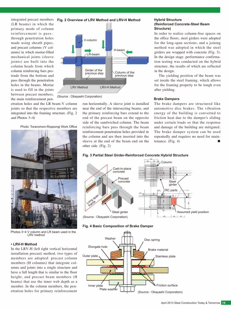
Rigid reinforced concrete framing was adopted for the building’s structure. The standard floor plan was 50.4 m × 50.4 m (7.2 m × 7 spans). For the high-rise office floors, steel girder framing with a length of 2~3 spans was adopted to realize wide,
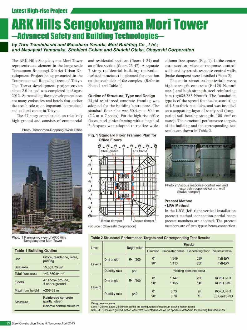
The ARK Hills Sengokuyama Mori Tower represents one element in the large-scale Toranomon-Roppongi District Urban De-velopment Project being promoted in the Toranomon and Roppoingi areas of Tokyo. The Tower development project covers about 2.0 ha and was completed in August 2012. Surrounding the redevelopment area are many embassies and hotels that anchor the area’s role as an important international and cultural center in Tokyo. The 47-story complex sits on relatively high ground and consists of commercial
and residential sections (floors 1-24) and an office section (floors 25-47). A separate 7-story residential building (seismic-isolated structure) is planned for erection on the south side of the complex. (Refer to Photo 1 and Table 1)
ARK Hills Sengokuyama Mori Tower─Advanced Safety and Building Technologies─
Table 1 Building OutlineOffice, residence, retail, parkingUse
15,367.75 m2Site area
143,550.04 m2Total floor area
47 above ground, 4 under groundFloors
+206.69 m Maximum height
Reinforced concrete (partly: steel)Seismic control structure
Structure
Table 2 Structural Performance Targets and Corresponding Test Results
Level 1Drift angle R<1/200
Level 2
Drift angle R<1/100
Ductility ratio µ<2
Direction Calculated value Generating floor Seismic wave
0° 1/349 28F Taft-EW90° 1/413 26F Taft-EW
0° 1/147 28F KOKUJI-HT90° 1/155 14F KOKUJI-KB
0° 0.73 9F KOKUJI-HT90° 0.76 1F EL Centro-NS
Results
Ductility ratio µ<1 Yielding does not occur
Level Target value
Design seismic waveLevel 1;25kine, Level 2;50kine modified the configuration of maximum ground motion speedKOKUJI- :Simulated ground motion waveform is created based on the spectrum defined in the Building Standards Law
Photo 1 Panoramic view of ARK Hills Sengokuyama Mori Tower
Photo: Toranomon-Roppongi Work OfficeFig. 1 Standard Floor Framing Plan for Office Floors
Brake damper Viscous damper
Steel girder RC frame
(Source : Obayashi Corporation)
column-free spaces (Fig. 1). In the center core section, viscous response-control walls and hysteresis response-control walls (brake dampers) were installed (Photo 2). The main structural materials were high-strength concrete (Fc120 N/mm2 max.) and high-strength steel reinforcing bars (σy685,785 N/mm2). The foundation type is of the spread foundation consisting of 4.5 m-thick mat slabs, and was installed on a supporting layer of sandy soil (long-period soil bearing strength: 100 t/m2 or more). The structural performance targets of the building and the corresponding test results are shown in Table 2.
Photo 2 Viscous response-control wall and hysteresis response-control wall (brake damper)
April 2013 Steel Construction Today & Tomorrow 14
Hybrid Structure (Reinforced Concrete-Steel Beam Structure)
Brake DampersThe brake dampers are structured like automotive disc brakes. The vibration energy of the building is converted to friction heat due to the damper’s sliding under certain loads so that the response and damage of the building are mitigated. The brake damper system can be used repeatedly and requires no need for main-tenance. (Fig. 4) ■
• LRV-H Method
(Source : Obayashi Corporation)
In order to realize column-free spaces on the office floors, steel girders were adopted for the long-span sections, and a joining method was adopted in which the steel girders are wrapped with concrete (Fig. 3). In the design stage, performance confirma-tion testing was conducted on the hybrid structure, the results of which are reflected in the design. The yielding position of the beam was set inside the steel framing, which allows for the framing property to be tough even after yielding.
Photo: Toranomon-Roppongi Work Office
Photos 3~4 V column and LR beam used in the LRV method
integrated precast members (LR beams) in which the primary mode of column re inforcement i s pass-through penetration holes made using sheath pipes, and precast columns (V col-umns) in which mortar-filled mechanical joints (sleeve joints) are built into the column heads from which column reinforcing bars pro-trude from the bottom and pass through the penetration holes in the beams. Mortar is used to fill in the joints between precast members, the main reinforcement pen-etration holes and the LR beam-V column joints so that the respective members are integrated into the framing structure. (Fig. 2 and Photos 3~4)
V-column
LR-beamH-beam
Column of the previous step
LRV Method LRV-H Method
Girder of the previous step
Fig. 4 Basic Composition of Brake Damper
Friction surface
Stainless plate
Brake material
Disc springWasher
Elongate hole
Outer plate
Inner platePlate washer
Fig. 2 Overview of LRV Method and LRV-H Method
In the LRV-H (left tight vertical horizontal installation precast) method, two types of members are adopted: precast column members (H columns) that integrate col-umns and joints into a single structure and have a full length that is similar to the floor height, and precast beam members (H beams) that use the inner web depth as a member. In the column members, the pen-etration holes for primary reinforcement
run horizontally. A sleeve joint is installed near the end of the intersecting beams, and the primary reinforcing bars extend to the end of the precast beam on the opposite side of the sandwiched column. The beam reinforcing bars pass through the beam reinforcement penetration holes provided in the column and are then inserted into the sleeve at the end of the beam end on the other side. (Fig. 2)
Fig. 3 Partial Steel Girder-Reinforced Concrete Hybrid Structure
Precast concrete
Cast-in-place concrete
Steel girder
Column
Steel girder
RC parts
Assumed yield position
Long span
frame
(Source : Obayashi Corporation)
(Source : Obayashi Corporation)
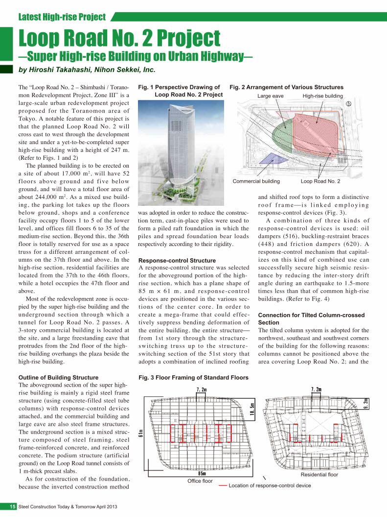
Fig. 3 Floor Framing of Standard Floors
Office floorResidential floor
Location of response-control device
Steel Construction Today & Tomorrow April 201315
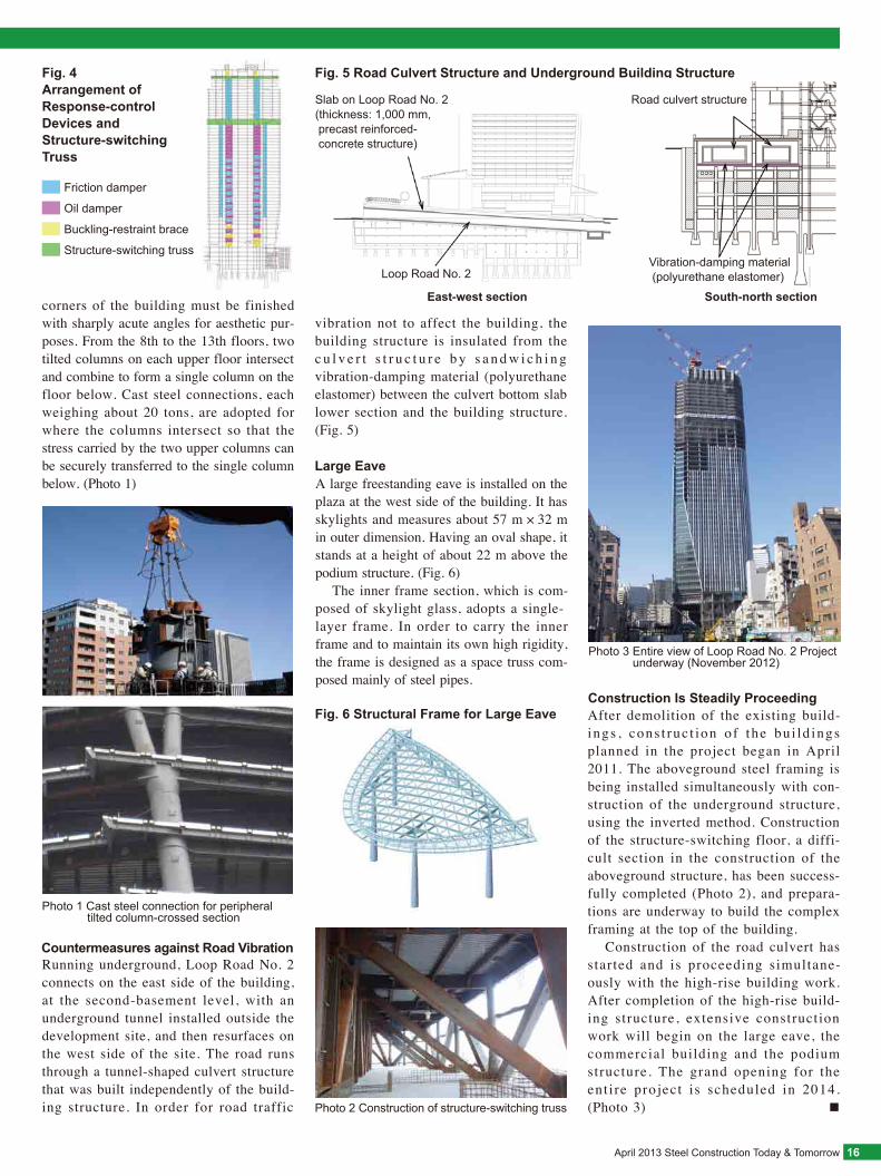
Loop Road No. 2 Project─Super High-rise Building on Urban Highway─by Hiroshi Takahashi, Nihon Sekkei, Inc.
Outline of Building Structure
Response-control Structure
Connection for Tilted Column-crossed Section
Fig. 1 Perspective Drawing of Loop Road No. 2 Project
Fig. 2 Arrangement of Various StructuresLarge eave High-rise building
Commercial building Loop Road No. 2
The tilted column system is adopted for the northwest, southeast and southwest corners of the building for the following reasons: columns cannot be positioned above the area covering Loop Road No. 2; and the
A response-control structure was selected for the aboveground portion of the high-rise section, which has a plane shape of 85 m × 61 m, and response-cont ro l devices are positioned in the various sec-t ions of the center core. In order to create a mega-frame that could effec-tively suppress bending deformation of the entire building, the entire structure⎯from 1st story through the structure-switching truss up to the structure-switching section of the 51st story that adopts a combination of inclined roofing
The aboveground section of the super high-rise building is mainly a rigid steel frame structure (using concrete-filled steel tube columns) with response-control devices attached, and the commercial building and large eave are also steel frame structures. The underground section is a mixed struc-ture composed of steel framing, steel frame-reinforced concrete, and reinforced concrete. The podium structure (artificial ground) on the Loop Road tunnel consists of 1 m-thick precast slabs. As for construction of the foundation, because the inverted construction method
The “Loop Road No. 2 – Shimbashi / Torano-mon Redevelopment Project, Zone III” is a large-scale urban redevelopment project proposed for the Toranomon area of Tokyo. A notable feature of this project is that the planned Loop Road No. 2 will cross east to west through the development site and under a yet-to-be-completed super high-rise building with a height of 247 m. (Refer to Figs. 1 and 2) The planned building is to be erected on a site of about 17,000 m2, will have 52 f loors above ground and f ive below ground, and will have a total floor area of about 244,000 m2. As a mixed use build-ing, the parking lot takes up the floors below ground, shops and a conference facility occupy floors 1 to 5 of the lower level, and offices fill floors 6 to 35 of the medium-rise section. Beyond this, the 36th floor is totally reserved for use as a space truss for a different arrangement of col-umns on the 37th floor and above. In the high-rise section, residential facilities are located from the 37th to the 46th floors, while a hotel occupies the 47th floor and above. Most of the redevelopment zone is occu-pied by the super high-rise building and the underground section through which a tunnel for Loop Road No. 2 passes. A 3-story commercial building is located at the site, and a large freestanding eave that protrudes from the 2nd floor of the high-rise building overhangs the plaza beside the high-rise building.
Latest High-rise Project
was adopted in order to reduce the construc-tion term, cast-in-place piles were used to form a piled raft foundation in which the piles and spread foundation bear loads respectively according to their rigidity.
and shifted roof tops to form a distinctive r o o f f r a m e⎯ i s l i n k e d e m p l o y i n g response-control devices (Fig. 3). A combina t ion o f th ree k inds o f response-control devices is used: oil dampers (516), buckling-restraint braces (448) and fr ict ion dampers (620). A response-control mechanism that capital-izes on this kind of combined use can successfully secure high seismic resis-tance by reducing the inter-story drift angle during an earthquake to 1.5-more times less than that of common high-rise buildings. (Refer to Fig. 4)
Friction damper
Oil damper
Buckling-restraint brace
Structure-switching truss
Fig. 4Arrangement of Response-control Devices and Structure-switching Truss
April 2013 Steel Construction Today & Tomorrow 16
Large Eave
Photo 1 Cast steel connection for peripheral tilted column-crossed section
Photo 2 Construction of structure-switching truss
Fig. 5 Road Culvert Structure and Underground Building Structure
Fig. 6 Structural Frame for Large Eave
Photo 3 Entire view of Loop Road No. 2 Project underway (November 2012)
Slab on Loop Road No. 2 (thickness: 1,000 mm, precast reinforced- concrete structure)
Loop Road No. 2
East-west section
Road culvert structure
Vibration-damping material (polyurethane elastomer)
South-north section
Construction Is Steadily ProceedingAfter demolition of the existing build-ings , cons t ruc t ion o f the bu i ld ings planned in the project began in April 2011. The aboveground steel framing is being installed simultaneously with con-struction of the underground structure, using the inverted method. Construction of the structure-switching floor, a diffi-cult section in the construction of the aboveground structure, has been success-fully completed (Photo 2), and prepara-tions are underway to build the complex framing at the top of the building. Construction of the road culvert has started and is proceeding simultane-ously with the high-rise building work. After completion of the high-rise build-ing structure, extensive construction work will begin on the large eave, the commercial building and the podium structure. The grand opening for the ent i re project is scheduled in 2014. (Photo 3) ■
A large freestanding eave is installed on the plaza at the west side of the building. It has skylights and measures about 57 m × 32 m in outer dimension. Having an oval shape, it stands at a height of about 22 m above the podium structure. (Fig. 6) The inner frame section, which is com-posed of skylight glass, adopts a single-layer frame. In order to carry the inner frame and to maintain its own high rigidity, the frame is designed as a space truss com-posed mainly of steel pipes.
Countermeasures against Road VibrationRunning underground, Loop Road No. 2 connects on the east side of the building, at the second-basement level, with an underground tunnel installed outside the development site, and then resurfaces on the west side of the site. The road runs through a tunnel-shaped culvert structure that was built independently of the build-ing structure. In order for road traffic
corners of the building must be finished with sharply acute angles for aesthetic pur-poses. From the 8th to the 13th floors, two tilted columns on each upper floor intersect and combine to form a single column on the floor below. Cast steel connections, each weighing about 20 tons, are adopted for where the columns intersect so that the stress carried by the two upper columns can be securely transferred to the single column below. (Photo 1)
vibration not to affect the building, the building structure is insulated from the c u l v e r t s t r u c t u r e b y s a n d w i c h i n g vibration-damping material (polyurethane elastomer) between the culvert bottom slab lower section and the building structure. (Fig. 5)
Steel Construction Today & Tomorrow April 201317
Latest High-rise Project
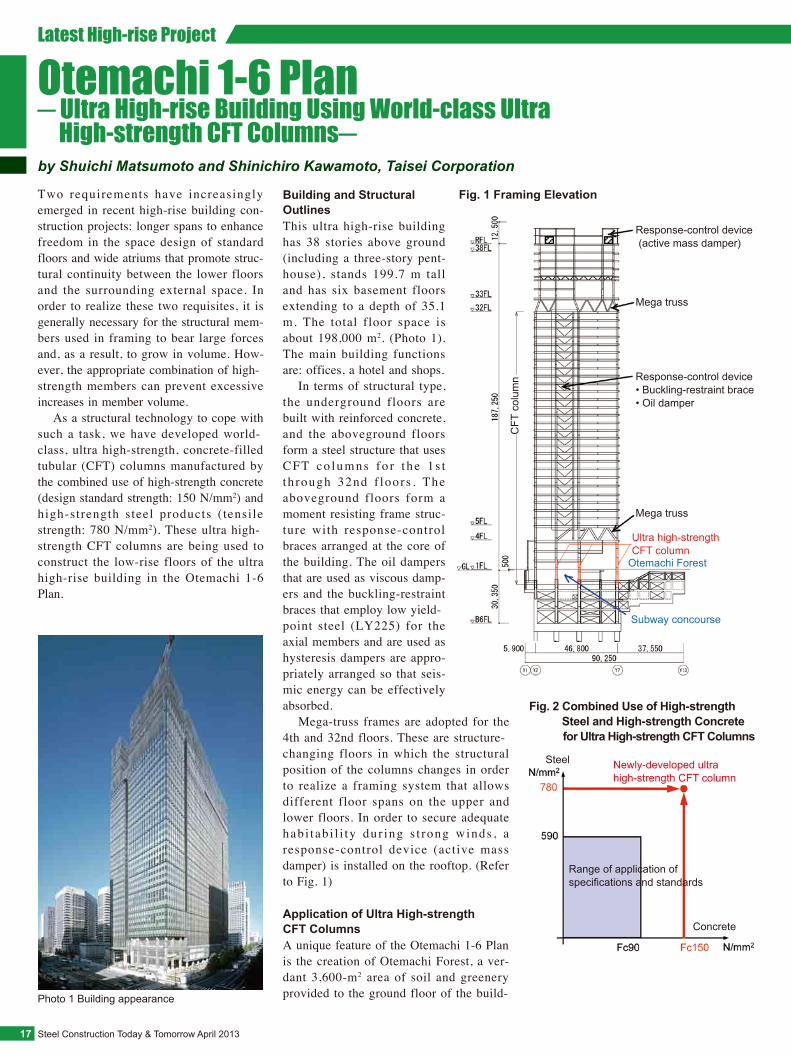
Otemachi 1-6 Plan─ Ultra High-rise Building Using World-class Ultra High-strength CFT Columns─by Shuichi Matsumoto and Shinichiro Kawamoto, Taisei Corporation
Fig. 1 Framing Elevation
Response-control device (active mass damper)
Mega truss
Response-control device• Buckling-restraint brace• Oil damper
Mega truss
Ultra high-strength CFT column
Otemachi Forest
Subway concourse
Fig. 2 Combined Use of High-strength Steel and High-strength Concrete for Ultra High-strength CFT Columns
Range of application of specifications and standards
Newly-developed ultra high-strength CFT column
Concrete
Steel
A unique feature of the Otemachi 1-6 Plan is the creation of Otemachi Forest, a ver-dant 3,600-m2 area of soil and greenery provided to the ground floor of the build-
This ultra high-rise building has 38 stories above ground (including a three-story pent-house), stands 199.7 m tall and has six basement floors extending to a depth of 35.1 m. The total floor space is about 198,000 m2. (Photo 1). The main building functions are: offices, a hotel and shops. In terms of structural type, the underground floors are built with reinforced concrete, and the aboveground floors form a steel structure that uses CFT co lumns fo r t he 1 s t th rough 32nd f loors . The aboveground floors form a moment resisting frame struc-ture with response-control braces arranged at the core of the building. The oil dampers that are used as viscous damp-ers and the buckling-restraint braces that employ low yield-point steel (LY225) for the axial members and are used as hysteresis dampers are appro-priately arranged so that seis-mic energy can be effectively absorbed. Mega-truss frames are adopted for the 4th and 32nd floors. These are structure-changing floors in which the structural position of the columns changes in order to realize a framing system that allows different floor spans on the upper and lower floors. In order to secure adequate hab i tab i l i ty dur ing s t rong winds , a response-control device (active mass damper) is installed on the rooftop. (Refer to Fig. 1)
Two requirements have increasingly emerged in recent high-rise building con-struction projects: longer spans to enhance freedom in the space design of standard floors and wide atriums that promote struc-tural continuity between the lower floors and the surrounding external space. In order to realize these two requisites, it is generally necessary for the structural mem-bers used in framing to bear large forces and, as a result, to grow in volume. How-ever, the appropriate combination of high-strength members can prevent excessive increases in member volume. As a structural technology to cope with such a task, we have developed world-class, ultra high-strength, concrete-filled tubular (CFT) columns manufactured by the combined use of high-strength concrete (design standard strength: 150 N/mm2) and high-strength steel products ( tensile strength: 780 N/mm2). These ultra high-strength CFT columns are being used to construct the low-rise floors of the ultra high-rise building in the Otemachi 1-6 Plan.
Building and Structural Outlines
Application of Ultra High-strength CFT Columns
Photo 1 Building appearance
CFT
col
umn
Otemachi Forest
: Ultra high-strength CFT column
April 2013 Steel Construction Today & Tomorrow 18
Photo 2 Ultra high-strength concrete-filled tubular (CFT) column
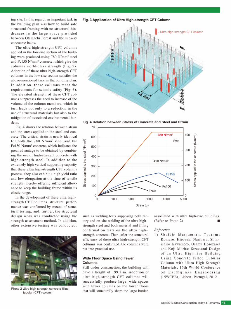
Fig. 3 Application of Ultra High-strength CFT Column
Fig. 4 Relation between Stress of Concrete and Steel and Strain
Stre
ss a
pplie
d to
the
conc
rete
(N/m
m2 )
Strain (μ)
00 1000 2000 3000 4000 500000
100
200
300
400
500
600
700
100
200
300
400780 N/mm2
490 N/mm2
Fc150
Fc100Fc60
steel
Stre
ss a
pplie
d to
the
stee
l (N
/mm
2 )
Still under construction, the building will have a height of 199.7 m. Adoption of ultra high-strength CFT columns will successfully produce large, wide spaces with fewer columns on the lower floors that will structurally share the large burden
Wide Floor Space Using Fewer Columns
1 ) S h u i c h i M a t s u m o t o , T s u t o m u Komuro, Hiroyuki Narihara, Shin-ichiro Kawamoto, Osamu Hosozawa and Koji Morita: Structural Design o f an Ul t ra High- r i se Bui ld ing Us ing Concre te F i l l ed Tubu la r Column with Ultra High Strength Materials, 15th World Conference o n E a r t h q u a k e E n g i n e e r i n g (15WCEE), Lisbon, Portugal, 2012.
Reference
ing site. In this regard, an important task in the building plan was how to build safe structural framing with no structural hin-drances in the large space provided between Otemachi Forest and the subway concourse below. The ultra high-strength CFT columns applied in the low-rise section of the build-ing were produced using 780 N/mm2 steel and Fc150 N/mm2 concrete, which give the columns world-class strength (Fig. 2). Adoption of these ultra high-strength CFT columns in the low-rise section satisfies the above-mentioned task in the building plan. In addit ion, these columns meet the requirements for seismic safety (Fig. 3). The elevated strength of these CFT col-umns suppresses the need to increase of the volume of the column members, which in turn leads not only to a reduction in the use of structural materials but also to the mitigation of associated environmental bur-dens. Fig. 4 shows the relation between strain and the stress applied to the steel and con-crete. The critical strain is nearly identical for both the 780 N/mm2 steel and the Fc150 N/mm2 concrete, which indicates the great advantage to be obtained by combin-ing the use of high-strength concrete with high-strength steel. In addition to the extremely high vertical supporting capacity that these ultra high-strength CFT columns possess, they also exhibit a high yield ratio and low elongation at the time of tensile strength, thereby offering sufficient allow-ance to keep the building frame within its elastic range. In the development of these ultra high-strength CFT columns, structural perfor-mance was confirmed by means of struc-tural testing, and, further, the structural design work was conducted using the strength assessment method. In addition, other extensive testing was conducted,
such as welding tests supposing both fac-tory and on-site welding of the ultra high-strength steel and both material and filling confirmation tests on the ultra high-strength concrete. Then, after the structural efficiency of these ultra high-strength CFT columns was confirmed, the columns were put into practical use.
associated with ultra high-rise buildings. (Refer to Photo 2) ■
STEEL CONSTRUCTION TODAY & TOMORROW
Japanese Society of Steel ConstructionYotsuya Mitsubishi Bldg. 9th Fl., 3-2-1 Yotsuya, Shinjuku-ku, Tokyo 160-0004, JapanPhone: 81-3-5919-1535 Fax: 81-3-5919-1536URL http://www.jssc.or.jp/english/index.html
The Japan Iron and Steel Federation3-2-10, Nihonbashi Kayabacho, Chuo-ku, Tokyo 103-0025, JapanPhone: 81-3-3669-4815 Fax: 81-3-3667-0245URL http://www.jisf.or.jp/en/index.html
Published jointly by Committee on Overseas Market Promotion, The Japan Iron and Steel FederationChairman (Editor): Takeshi Oki
Edited by
Publ ished three t imes per year, STEEL CONSTRUCTION TODAY & TOMORROW is circulated to interested persons, companies and public organizations to promote a better understanding of steel products and their application in the construction industry. Any part of this publication may be reproduced with our permission. To download content (PDF format), please go our website at: http://www.jisf.or.jp/en/activitity/sctt/index.html. We welcome your comments about the publication and ask that you contact us at: [email protected].
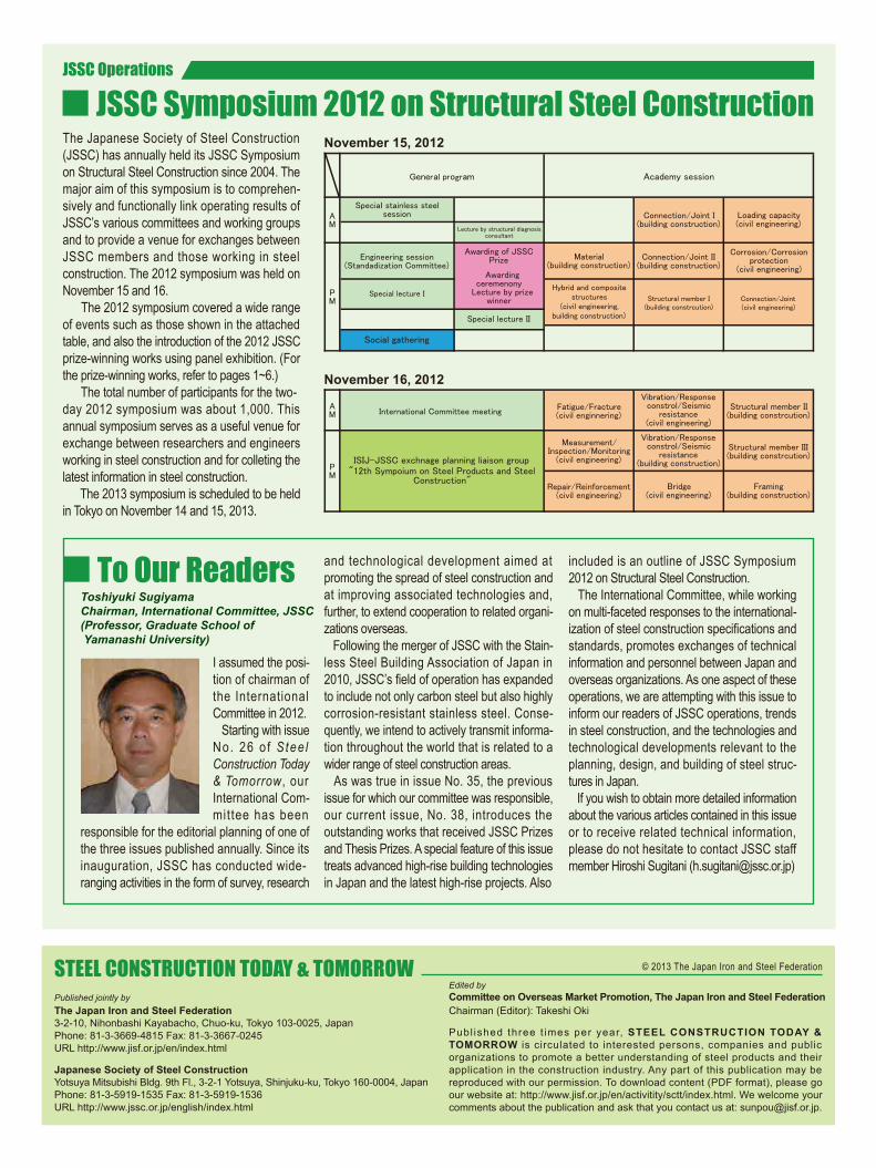
JSSC Operations
JSSC Symposium 2012 on Structural Steel Construction
To Our Readers
The Japanese Society of Steel Construction (JSSC) has annually held its JSSC Symposium on Structural Steel Construction since 2004. The major aim of this symposium is to comprehen-sively and functionally link operating results of JSSC’s various committees and working groups and to provide a venue for exchanges between JSSC members and those working in steel construction. The 2012 symposium was held on November 15 and 16. The 2012 symposium covered a wide range of events such as those shown in the attached table, and also the introduction of the 2012 JSSC prize-winning works using panel exhibition. (For the prize-winning works, refer to pages 1~6.) The total number of participants for the two-day 2012 symposium was about 1,000. This annual symposium serves as a useful venue for exchange between researchers and engineers working in steel construction and for colleting the latest information in steel construction. The 2013 symposium is scheduled to be held in Tokyo on November 14 and 15, 2013.
November 15, 2012
November 16, 2012
I assumed the posi-tion of chairman of the International Committee in 2012. Starting with issue No. 26 o f Stee l Construction Today & Tomorrow, our International Com-mittee has been
responsible for the editorial planning of one of the three issues published annually. Since its inauguration, JSSC has conducted wide-ranging activities in the form of survey, research
and technological development aimed at promoting the spread of steel construction and at improving associated technologies and, further, to extend cooperation to related organi-zations overseas. Following the merger of JSSC with the Stain-less Steel Building Association of Japan in 2010, JSSC’s field of operation has expanded to include not only carbon steel but also highly corrosion-resistant stainless steel. Conse-quently, we intend to actively transmit informa-tion throughout the world that is related to a wider range of steel construction areas. As was true in issue No. 35, the previous issue for which our committee was responsible, our current issue, No. 38, introduces the outstanding works that received JSSC Prizes and Thesis Prizes. A special feature of this issue treats advanced high-rise building technologies in Japan and the latest high-rise projects. Also
© 2013 The Japan Iron and Steel Federation
Toshiyuki SugiyamaChairman, International Committee, JSSC(Professor, Graduate School of Yamanashi University)
included is an outline of JSSC Symposium 2012 on Structural Steel Construction. The International Committee, while working on multi-faceted responses to the international-ization of steel construction specifications and standards, promotes exchanges of technical information and personnel between Japan and overseas organizations. As one aspect of these operations, we are attempting with this issue to inform our readers of JSSC operations, trends in steel construction, and the technologies and technological developments relevant to the planning, design, and building of steel struc-tures in Japan. If you wish to obtain more detailed information about the various articles contained in this issue or to receive related technical information, please do not hesitate to contact JSSC staff member Hiroshi Sugitani ([email protected])