Embed Size (px)
Citation preview
Material Data Sheet No. 4022March 2002 Edition
VDM® Alloy B-2Nimofer 6928
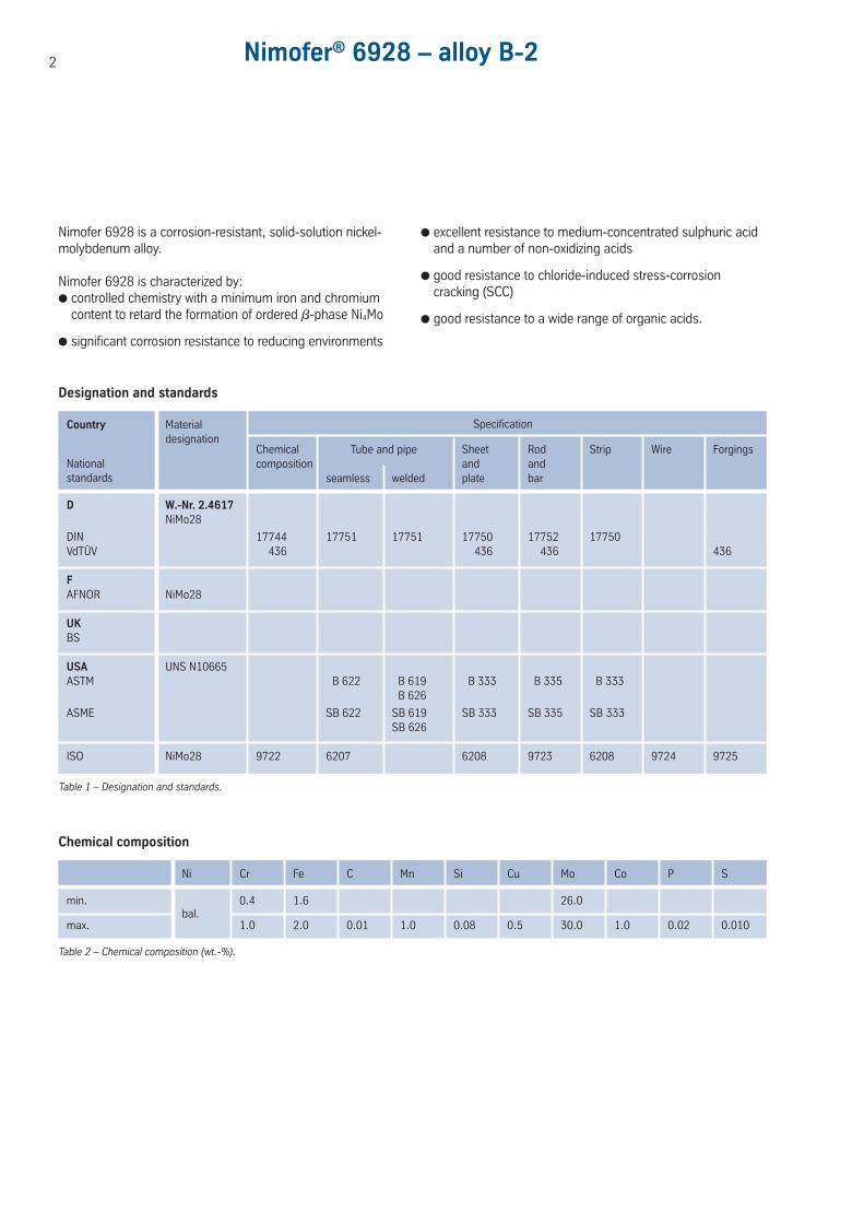
2 Nimofer® 6928 – alloy B-2
Nimofer 6928 is a corrosion-resistant, solid-solution nickel-molybdenum alloy.
Nimofer 6928 is characterized by: controlled chemistry with a minimum iron and chromium
content to retard the formation of ordered !-phase Ni4Mo
significant corrosion resistance to reducing environments
excellent resistance to medium-concentrated sulphuric acidand a number of non-oxidizing acids
good resistance to chloride-induced stress-corrosion cracking (SCC)
good resistance to a wide range of organic acids.
Ni Cr Fe C Mn Si Cu Mo Co P S
min. 0.4 1.6 26.0
max.bal.
1.0 2.0 0.01 1.0 0.08 0.5 30.0 1.0 0.02 0.010
SpecificationCountry Materialdesignation
Nationalstandards
Designation and standards
Chemical Tube and pipe Sheet Rod Strip Wire Forgingscomposition and and
seamless welded plate bar
Chemical composition
D W.-Nr. 2.4617NiMo28
DIN 17744 17751 17751 17750 17752 17750VdTÜV 436 436 436 436
FAFNOR NiMo28
UKBS
USA UNS N10665ASTM B 622 B 619 B 333 B 335 B 333
B 626
ASME SB 622 SB 619 SB 333 SB 335 SB 333SB 626
ISO NiMo28 9722 6207 6208 9723 6208 9724 9725
Table 1 – Designation and standards.
Table 2 – Chemical composition (wt.-%).
3
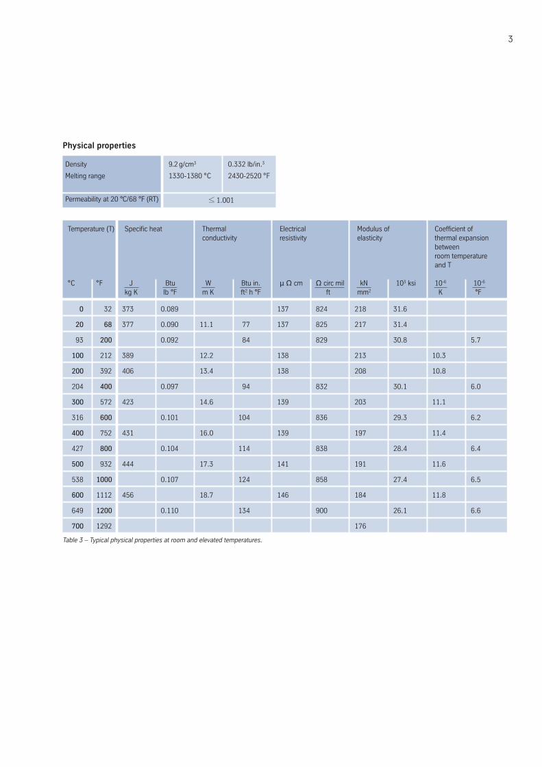
0 32 373 0.089 137 824 218 31.6
20 68 377 0.090 11.1 77 137 825 217 31.4
93 200 0.092 84 829 30.8 5.7
100 212 389 12.2 138 213 10.3
200 392 406 13.4 138 208 10.8
204 400 0.097 94 832 30.1 6.0
300 572 423 14.6 139 203 11.1
316 600 0.101 104 836 29.3 6.2
400 752 431 16.0 139 197 11.4
427 800 0.104 114 838 28.4 6.4
500 932 444 17.3 141 191 11.6
538 1000 0.107 124 858 27.4 6.5
600 1112 456 18.7 146 184 11.8
649 1200 0.110 134 900 26.1 6.6
700 1292 176
Physical properties
Density
Melting range
Permeability at 20 °C/68 °F (RT)
9.2 g/cm3 0.332 lb/in.3
1330-1380 °C 2430-2520 °F
≤ 1.001
Temperature (T) Specific heat Thermal Electrical Modulus of Coefficient ofconductivity resistivity elasticity thermal expansion
betweenroom temperatureand T
°C °F J Btu W Btu in. µ Ω cm Ω circ mil kN 103 ksi 10-6 10-6
kg K lb °F m K ft2 h °F ft mm2 K °F
Table 3 – Typical physical properties at room and elevated temperatures.
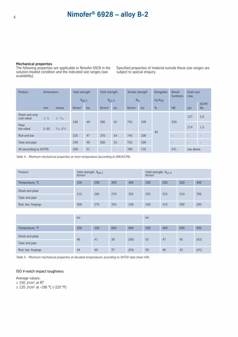
4 Nimofer® 6928 – alloy B-2
Mechanical propertiesThe following properties are applicable to Nimofer 6928 in thesolution-treated condition and the indicated size ranges (seeavailability).
Specified properties of material outside these size ranges aresubject to special enquiry.
Sheet and stripcold rolled ≤ 5 ≤ 3/16
127 3.0
Plate340 49 380 55 755 109 250
hot rolled 5–65 3/16–21/2
40
214 1.5
Rod and bar 325 47 370 54 745 108 – – –
Tube and pipe 340 49 360 52 755 109 – – –
All (according to ASTM) 350 51 – – 760 110 241 see above
Table 4 – Minimum mechanical properties at room temperature (according to DIN/ASTM).
Product Dimensions Yield strength Yield strength Tensile strength Elongation Brinell Grain sizehardness max.
Rp0.2 Rp1.0 Rm A5/A50ASTM
mm inches N/mm2 ksi N/mm2 ksi N/mm2 ksi % HB µm No.
Sheet and plate315 285 270 255 355 325 310 295
Tube and pipe
Rod, bar, forgings 300 275 255 240 340 315 300 285
Product Yield strength, Rp0.2 Yield strength, Rp1.0N/mm2 N/mm2
Temperature, °C 100 200 300 400 100 200 300 400
Sheet and plate46 41 39 (36) 52 47 45 (42)
Tube and pipe
Rod, bar, forgings 44 40 37 (34) 50 46 43 (41)
ksi ksi
Temperature, °F 200 400 600 800 200 400 600 800
Table 5 – Minimum mechanical properties at elevated temperatures according to VdTÜV data sheet 436.
ISO V-notch impact toughness
Average values:≥ 150 J/cm2 at RT≥ 120 J/cm2 at -196 °C (-320 °F)
Temperature Maximum allowable stress
°C °F N/mm2 ksi1) 1) 2) 2)
38 100 27.5 27.5
93 200 27.5 27.5
100 212 190 190
149 300 27.5 27.5
200 392 190 190
204 400 27.5 27.5
260 500 27.5 27.5
300 572 188 188
316 600 27.2 27.2
371 700 26.6 27.1
400 752 180 180
427 800 25.6 26.8
1) metric values determined by interpolation2) conditional stress values (see below)
Table 6 – Maximum allowable stress values in tension according to ASME UNF-23.3, SB 333.
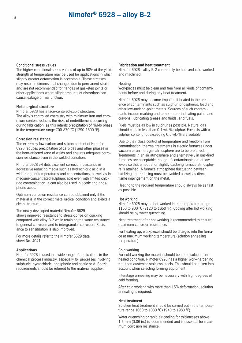
Fig. 2 – Typical short-time mechanical properties of solution-treatedNimofer 6928 (1080 °C/1980 °F/WQ) at elevated temperatures.
800
700
600
500
400
300
200
100
Stre
ss, N
/mm
2
RT 200 400
Temperature, °C
120
110
100
90
80
70
60
50
40
30
20
10
Stre
ss, k
si
Tensile strength
5
900
850
800
750
700
650
1650
1600
1500
1400
1300
12000.1 1
Time, h10
A
B
C
1.13% Fe + 0.47% Cr
Av < 100 J
1.75% Fe + 0.68% Cr
Elon
gatio
n, %
0.2% Yield strength
Elongation
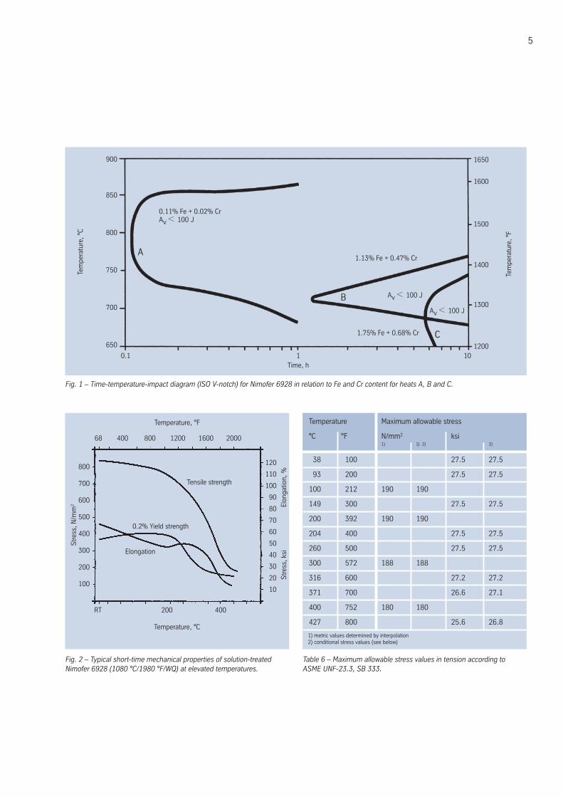
Fig. 1 – Time-temperature-impact diagram (ISO V-notch) for Nimofer 6928 in relation to Fe and Cr content for heats A, B and C.
Tem
pera
ture
, °C
Tem
pera
ture
, °F
0.11% Fe + 0.02% Cr Av < 100 J
Temperature, °F
68 400 800 1200 1600 2000
Av < 100 J
Conditional stress valuesThe higher conditional stress values of up to 90% of the yieldstrength at temperature may be used for applications in whichslightly greater deformation is acceptable. These stressesmay result in dimensional changes due to permanent strainand are not recommended for flanges of gasketed joints orother applications where slight amounts of distortions cancause leakage or malfunction.
Metallurgical structureNimofer 6928 has a face-centered-cubic structure. The alloy’s controlled chemistry with minimum iron and chro-mium content reduces the risks of embrittlement occurringduring fabrication, as this retards precipitation of Ni4Mo phasein the temperature range 700-870 °C (1290-1600 °F).
Corrosion resistanceThe extremely low carbon and silicon content of Nimofer6928 reduces precipitation of carbides and other phases inthe heat-affected zone of welds and ensures adequate corro-sion resistance even in the welded condition.
Nimofer 6928 exhibits excellent corrosion resistance inaggressive reducing media such as hydrochloric acid in awide range of temperatures and concentrations, as well as inmedium-concentrated sulphuric acid even with limited chlo-ride contamination. It can also be used in acetic and phos-phoric acids.
Optimum corrosion resistance can be obtained only if thematerial is in the correct metallurgical condition and exibits aclean structure.
The newly developed material Nimofer 6629 shows improved resistance to stress-corrosion crackingcompared with alloy B-2 while retaining the same resistanceto general corrosion and to intergranular corrosion. Resist-ance to sensitization is also improved.
For more details refer to the Nimofer 6629 datasheet No. 4041.
ApplicationsNimofer 6928 is used in a wide range of applications in thechemical process industry, especially for processes involvingsulphuric, hydrochloric, phosphoric and acetic acid. Spezialrequirements should be referred to the material supplier.
Fabrication and heat treatmentNimofer 6928 - alloy B-2 can readily be hot- and cold-workedand machined.
HeatingWorkpieces must be clean and free from all kinds of contami-nants before and during any heat treatment.
Nimofer 6928 may become impaired if heated in the pres-ence of contaminants such as sulphur, phosphorus, lead andother low-melting-point metals. Sources of such contami-nants include marking and temperature-indicating paints andcrayons, lubricating grease and fluids, and fuels.
Fuels must be as low in sulphur as possible. Natural gasshould contain less than 0.1 wt.-% sulphur. Fuel oils with asulphur content not exceeding 0.5 wt.-% are suitable.
Due to their close control of temperature and freedom fromcontamination, thermal treatments in electric furnaces undervacuum or an inert gas atmosphere are to be preferred.Treatments in an air atmosphere and alternatively in gas-firedfurnaces are acceptable though, if contaminants are at lowlevels so that a neutral or slightly oxidizing furnace atmosphe-re is attained. A furnace atmosphere fluctuating betweenoxidizing and reducing must be avoided as well as directflame impingement on the metal.
Heating to the required temperature should always be as fastas possible.
Hot workingNimofer 6928 may be hot-worked in the temperature range1160 to 900 °C (2120 to 1650 °F). Cooling after hot workingshould be by water quenching.
Heat treatment after hot working is recommended to ensuremaximum corrosion resistance.
For heating up, workpieces should be charged into the furna-ce at maximum working temperature (solution annealingtemperature).
Cold workingFor cold working the material should be in the solution-an-nealed condition. Nimofer 6928 has a higher work-hardeningrate than austenitic stainless steels. This should be taken intoaccount when selecting forming equipment.
Interstage annealing may be necessary with high degrees ofcold forming.
After cold working with more than 15% deformation, solutionannealing is required.
Heat treatmentSolution heat treatment should be carried out in the tempera-ture range 1060 to 1080 °C (1940 to 1980 °F).
Water quenching or rapid air cooling for thicknesses above1.5 mm (0.06 in.) is recommended and is essential for maxi-mum corrosion resistance.
6 Nimofer® 6928 – alloy B-2
7
For any thermal treatment the material should be chargedinto the furnace at temperature. Also for any thermal treat-ment operation the precautions concerning cleanlinessmentioned earlier under ‘Heating’ must be observed.
Descaling and picklingOxides of Nimofer 6928 and discoloration adjacent to weldsare more adherent than on stainless steels. Grinding with veryfine abrasive belts or discs is recommended. Care should betaken to prevent tarnishing.
Before pickling, which may be performed in a nitric/hydro-fluoric acid mixture with proper control of pickling time andtemperature, the surface oxide layer must be broken up byabrasive blasting, by carefully performed grinding or bypretreatment in a fused salt bath.
Due to the alloy’s sensitivity to oxidizing media, relatively highmass loss rates along with heavy formation of nitrous gasesmay be expected.
MachiningNimofer 6928 should be machined in the heat-treated condi-tion. As the alloy exhibits a high work-hardening rate only lowcutting speeds should be used compared with low-alloyedstandard austenitic stainless steels. Tools should be engagedat all times. An adequate depth of cut is important in order tocut below the previously formed work-hardened zone.
WeldingWhen welding nickel-base alloys, the following instructionsshould be adhered to:
WorkplaceThe workplace should be in a separate location, well awayfrom areas where carbon steel fabrication takes place. Maxi-mum cleanliness and avoidance of draughts are paramount.
Auxiliaries, clothingClean fine leather gloves and clean working clothes should beused.
Tools and machinesTools used for nickel-base alloys and stainless steels mustnot be used for other materials. Brushes should be made ofstainless materials.
Fabricating and working machinery such as shears, pressesor rollers should be fitted with means (felt, cardboard, plasticsheeting) of avoiding contamination of the metal with ferrousparticles, which can be pressed into the surface and thus leadto corrosion.
CleaningCleaning of the base metal in the weld area (both sides) andof the filler metal (e.g. welding rod) should be carried out withACETONE.
Trichlorethylene (TRI), perchlorethylene (PER) and carbontetrachloride (TETRA) must not be used.
Edge preparationThis should preferably be done by mechanical means byturning, milling or planing; plasma cutting is also possible.However, in the latter case the cut edge (the face to be welded)must be finished off cleanly. Careful grinding without overheat-ing is permitted. Also a zone approximately 25 mm (1 in.) wideon each side of the joint should be ground to bright metal.
Included angleThe different physical characteristics of nickel-base alloys andspecial stainless steels compared with carbon steel generallymanifest themselves in a lower thermal conductivity and ahigher rate of thermal expansion.
Fig. 3 – Edge preparation for welding of nickel-base alloys and specialstainless steels.
Single-V weld
Platethickness 16-25 mm
up to 2 mm
60 - 70°
0-2 mm
approx. 1.5 mm
60 - 70°
Single-U weld
Sheet/platethickness 2.5-15 mm
approx.2 mm
Double-V weld
Platethickness 12-25 mm
approx.2 mm
approx.2 mm
Straight butt weld
Sheet thickness up to 2.5 mm
15°
R=6
2 mm
Double-U weldPlate thickness over 25 mm
approx.2 mm
15°
R=6
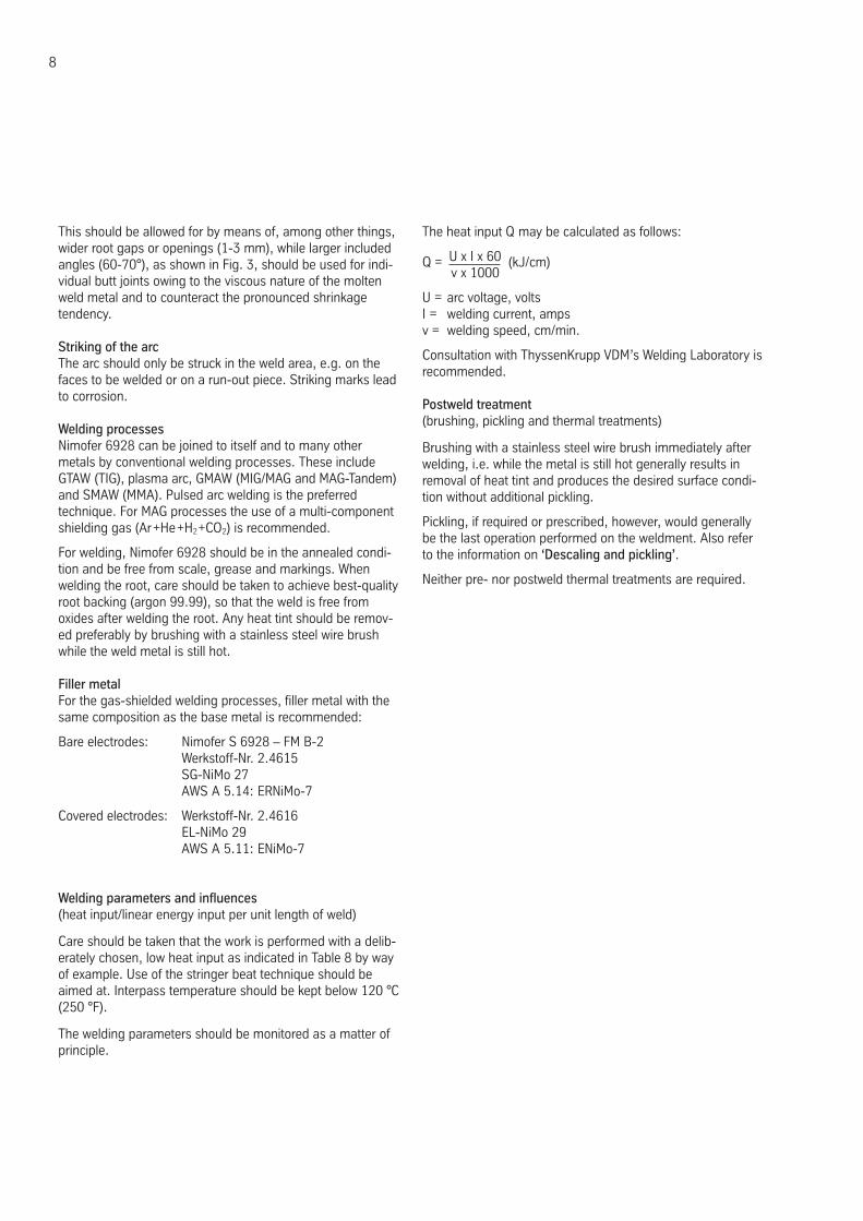
This should be allowed for by means of, among other things,wider root gaps or openings (1-3 mm), while larger includedangles (60-70°), as shown in Fig. 3, should be used for indi-vidual butt joints owing to the viscous nature of the moltenweld metal and to counteract the pronounced shrinkagetendency.
Striking of the arcThe arc should only be struck in the weld area, e.g. on thefaces to be welded or on a run-out piece. Striking marks leadto corrosion.
Welding processesNimofer 6928 can be joined to itself and to many othermetals by conventional welding processes. These includeGTAW (TIG), plasma arc, GMAW (MIG/MAG and MAG-Tandem)and SMAW (MMA). Pulsed arc welding is the preferred technique. For MAG processes the use of a multi-componentshielding gas (Ar+He+H2+CO2) is recommended.
For welding, Nimofer 6928 should be in the annealed condi-tion and be free from scale, grease and markings. Whenwelding the root, care should be taken to achieve best-qualityroot backing (argon 99.99), so that the weld is free fromoxides after welding the root. Any heat tint should be remov-ed preferably by brushing with a stainless steel wire brushwhile the weld metal is still hot.
Filler metalFor the gas-shielded welding processes, filler metal with thesame composition as the base metal is recommended:
Bare electrodes: Nimofer S 6928 – FM B-2Werkstoff-Nr. 2.4615SG-NiMo 27AWS A 5.14: ERNiMo-7
Covered electrodes: Werkstoff-Nr. 2.4616EL-NiMo 29AWS A 5.11: ENiMo-7
Welding parameters and influences(heat input/linear energy input per unit length of weld)
Care should be taken that the work is performed with a delib-erately chosen, low heat input as indicated in Table 8 by wayof example. Use of the stringer beat technique should beaimed at. Interpass temperature should be kept below 120 °C(250 °F).
The welding parameters should be monitored as a matter ofprinciple.
The heat input Q may be calculated as follows:
Q = U x I x 60 (kJ/cm)v x 1000
U = arc voltage, voltsI = welding current, ampsv = welding speed, cm/min.
Consultation with ThyssenKrupp VDM’s Welding Laboratory is recommended.
Postweld treatment(brushing, pickling and thermal treatments)
Brushing with a stainless steel wire brush immediately afterwelding, i.e. while the metal is still hot generally results inremoval of heat tint and produces the desired surface condi-tion without additional pickling.
Pickling, if required or prescribed, however, would generallybe the last operation performed on the weldment. Also referto the information on ‘Descaling and pickling’.
Neither pre- nor postweld thermal treatments are required.
8
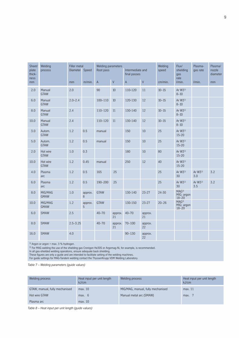
Sheet/ Welding Filler metal Welding parameters Welding Flux/ Plasma- Plasma/plate process Diameter Speed Root pass Intermediate and speed shielding gas rate nozzlethick- final passes gas diameterness ratemm mm m/min. A V A V cm/min. l/min. l/min. mm
Table 7 – Welding parameters (guide values)
1) Argon or argon + max. 3 % hydrogen.2) For MAG welding the use of the shielding gas Cronigon He30S or Argomag-Ni, for example, is recommended.In all gas-shielded welding operations, ensure adequate back shielding.These figures are only a guide and are intended to facilitate setting of the welding machines.For guide settings for MAG-Tandem welding contact the ThyssenKrupp VDM Welding Laboratory.
2.0 Manual 2.0 90 10 110-120 11 10–15 Ar W31)
GTAW 8–10
6.0 Manual 2.0–2.4 100–110 10 120-130 12 10–15 Ar W31)
GTAW 8–10
8.0 Manual 2.4 110–120 11 130-140 12 10–15 Ar W31)
GTAW 8–10
10.0 Manual 2.4 110–120 11 130-140 12 10–15 Ar W31)
GTAW 8–10
3.0 Autom. 1.2 0.5 manual 150 10 25 Ar W31)
GTAW 15-20
5.0 Autom. 1.2 0.5 manual 150 10 25 Ar W31)
GTAW 15-20
2.0 Hot wire 1.0 0.3 180 10 80 Ar W31)
GTAW 15-20
10.0 Hot wire 1.2 0.45 manual 250 12 40 Ar W31)
GTAW 15-20
4.0 Plasma 1.2 0.5 165 25 25 Ar W31) Ar W31) 3.2arc 30 3.0
6.0 Plasma 1.2 0.5 190–200 25 25 Ar W31) Ar W31) 3.2arc 30 3.5
8.0 MIG/MAG 1.0 approx. GTAW 130-140 23-27 24-30GMAW 8
10.0 MIG/MAG 1.2 approx. GTAW 130-150 23-27 20–26GMAW 5
6.0 SMAW 2.5 40–70 approx. 40–70 approx.21 21
8.0 SMAW 2.5–3.25 40–70 approx. 70–100 approx.21 22
16.0 SMAW 4.0 90–130 approx.22
Welding process Heat input per unit length Welding process Heat input per unit lengthkJ/cm kJ/cm
GTAW, manual, fully mechanised max. 10 MIG/MAG, manual, fully mechanised max. 11
Hot wire GTAW max. 6 Manual metal arc (SMAW) max. 7
Plasma arc max. 10
Table 8 – Heat input per unit length (guide values)
9
MAG2)
MIG: argon18–20MAG2)
MIG: argon18–20
Thickness hr / cr Width1) Length1)
mm mm mm
1.10 – < 1.50 cr 2000 8000
1.50 – < 3.00 cr 2500 8000
3.00 – < 7.50 cr / hr 2500 8000
7.50 – ≤ 25.00 hr 2500 80002)
> 25.001) hr 25002) 80002)
inches inches inches
0.043 – < 0.060 cr 80 320
0.060 – < 0.120 cr 100 320
0.120 – < 0.300 cr / hr 100 320
0.300 – ≤ 1.000 hr 100 3202)
> 1.0001) hr 1002) 3202)
Product Weight Thickness O.D.1) I.D.1)
kg mm mm mm
Disc ≤10000 ≤300 ≤3000
Ring ≤ 3000 ≤200 ≤ 2500 on request
Ibs inches inches inches
Disc ≤22000 ≤12 ≤120
Ring ≤ 6600 ≤ 8 ≤100 on request
Product Forged1) Rolled1) Drawn1)
mm mm mm
Rod (o.d.) ≤600 8–100 12–65
Bar, square (a) 40–600 15–280 not standard
Bar, flat (a x b) (40–80) (5–20) (10–20)x x x(200–600) (120–600) (30–80)
Bar, hexagonal (s) 40–80 13–41 ≤50
inches inches inches
Rod (o.d.) ≤24 5/16–4 1/2–21/2
Bar, square (a) 15/8–24 10/16–11 not standard
Bar, flat (a x b) (15/8–31/8) (3/16–3/4) (3/8–3/4)x x x(8–24) (43/4–24) (11/4–31/8)
Bar, hexagonal (s) 15/8–31/8 1/2–15/8 ≤2
AvailabilityNimofer 6928 is available in the following standard productforms:
Sheet & plate(for cut-to-length availability, refer to strip)
Conditions:hot or cold rolled (hr, cr)thermally treated and pickled
1) other sizes subject to special enquiry2) depending on piece weight
1) other sizes subject to special enquiry
Discs and ringsConditions:hot rolled or forged,thermally treated,pickled or machined
Rod & barConditions:forged, rolled, drawn,thermally treated,pickled, machined, peeled or ground
1) other sizes and conditions subject to special enquiry
Nimofer® 6928 – alloy B-210
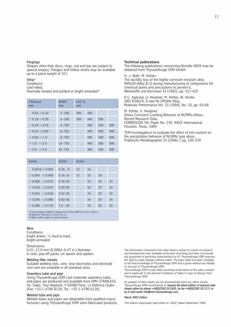
Thickness Width3) Coil I.D.mm mm mm
0.04–≤0.10 4–200 300 400
> 0.10–≤0.20 4–350 300 400 500
> 0.20–≤0.25 4–750 400 500 600
> 0.25–≤0.60 6–750 400 500 600
> 0.60–≤1.0 8–750 400 500 600
> 1.0 –≤2.0 15–750 400 500 600
> 2.0 –≤3.0 25–750 400 500 600
inches inches inches
0.0016–≤0.004 0.16– 8 12 16
> 0.004 –≤0.008 0.16–14 12 16 20
> 0.008 –≤0.010 0.16–30 16 20 24
> 0.010 –≤0.024 0.20–30 16 20 24
> 0.024 –≤0.040 0.32–30 16 20 24
> 0.040 –≤0.080 0.60–30 16 20 24
> 0.080 –≤0.120 1.0 –30 16 20 24
ForgingsShapes other than discs, rings, rod and bar are subject tospecial enquiry. Flanges and hollow shafts may be availableup to a piece weight of 10 t.
Strip1)
Conditions:cold rolled,thermally treated and pickled or bright annealed2)
1) Cut-to-length available in lengths from 250 to 4000 mm (10 to 158 in.)2) Maximum thickness 3 mm (0.125 in.)3) Wider widths subject to special enquiry
WireConditions:bright drawn, 1/4 hard to hard,bright annealed
Dimensions:0.01–12.0 mm (0.0004–0.47 in.) diameter,in coils, pay-off packs, on spools and spiders
Welding filler metalsSuitable welding rods, wire, strip electrodes and electrodecore wire are available in all standard sizes.
Seamless tube and pipeUsing ThyssenKrupp VDM cast materials seamless tubes and pipes are produced and available from DMV STAINLESSInt. Sales, Tour Neptune, F-92086 Paris, La Defence Cedex (Fax: +33-1-4796 8126; Tel.: +33-1-4796 8128).
Welded tube and pipeWelded tubes and pipes are obtainable from qualified manu-facturers using ThyssenKrupp VDM semi-fabricated products.
The information contained in this data sheet is based on results of researchand development work available at the time of printing and does not provideany guarantee of particular characteristics or fit. ThyssenKrupp VDM reservesthe right to make changes without notice. The data sheet has been compiledto the best knowledge of ThyssenKrupp VDM and is given without any liabilityon the part of ThyssenKrupp VDM.ThyssenKrupp VDM is only liable according to the terms of the sales contract and in particular to the General Conditions of Sales in case of delivery fromThyssenKrupp VDM.
As updates of data sheets are not automatically send out, when issued, ThyssenKrupp VDM recommends to rreeqquueesstt tthhee llaatteesstt eeddiittiioonn ooff rreeqquuiirreedd ddaattaasshheeeettss eeiitthheerr bbyy pphhoonnee ++4499((00))22339922 5555 22449933,, bbyy ffaaxx ++4499((00))22339922 5555 22111111 oorrbbyy EE--mmaaiill uunnddeerr iinnffoo@@vvddmm..tthhyysssseennkkrruupppp..ccoomm..
MMaarrcchh 22000022 EEddiittiioonn..
This edition supersedes data sheet no. 4022, dated September 1996.
11
Technical publicationsThe following publications concerning Nimofer 6928 may beobtained from ThyssenKrupp VDM GmbH:
H.-J. Büth, M. Köhler:The ductility loss of the highly corrosion resistant alloyNiMo28 (Alloy B-2) during manufacturing of components forchemical plants and precautions to prevent it, Werkstoffe und Korrosion 43 (1992), pp. 421-425
D.C. Agarwal, U. Heubner, M. Köhler, W. Herda:UNS N10629: A new Ni-28%Mo Alloy,Materials Performance Vol. 33 (1994), No. 10, pp. 64-68
M. Köhler, U. Heubner:Stress Corrosion Cracking Behavior of Ni28Mo-Alloys,Recent Research Data,CORROSION ‘94, Paper No. 230, NACE InternationalHouston, Texas, 1994
TEM-Investigations to evaluate the effect of iron content onthe precipitation behavior of Ni28Mo type alloys,Praktische Metallographie 33 (1996) 7, pp. 330-339
Imprint
VDM Metals GmbHPlettenberger Straße 258791 WerdohlGermany
Phone +49 (0) 2392 55-0Fax +49 (0) 2392 55-2217
Date of publicationMarch 2002
PublisherVDM Metals GmbHPlettenberger Straße 258791 WerdohlGermany
DisclaimerAll information contained in this data sheet are based on the results of research and development work carried out by VDM Metals GmbH, and the data contained in the specifications and standards listed available at the time of printing. The information does not represent a guarantee of specific properties. VDM Metals reserves the right to change information without notice. All information contained in this data sheet is compiled to the best of our knowledge and is provided without liability. Deliveries and services are subject exclusively to the relevant contractual conditions and the General Terms and Conditions issued by VDM Metals GmbH. Use of the most up-to-date version of this data sheet is the responsibility of the customer.