Embed Size (px)
Citation preview
VDM® Alloy 751
Nicrofer 7016 TiAl
Material Data Sheet No. 4047
November 2017
November 2017 VDM® Alloy 751 2
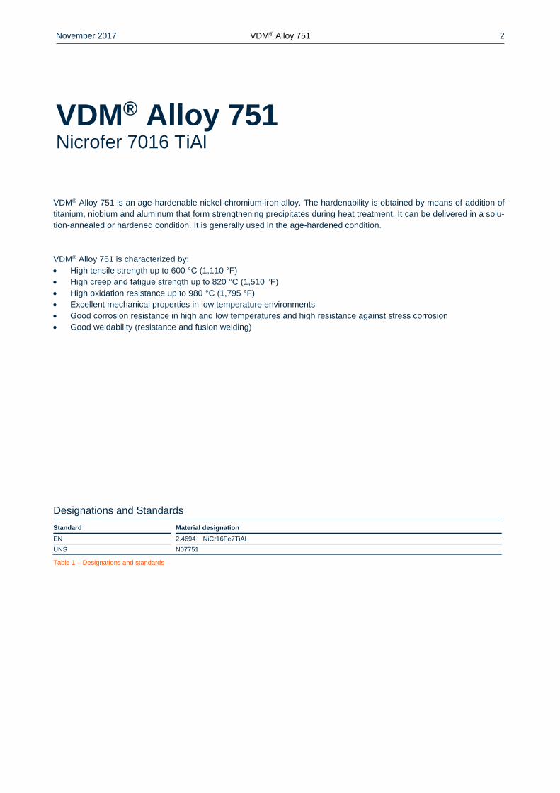
VDM® Alloy 751 is an age-hardenable nickel-chromium-iron alloy. The hardenability is obtained by means of addition of
titanium, niobium and aluminum that form strengthening precipitates during heat treatment. It can be delivered in a solu-
tion-annealed or hardened condition. It is generally used in the age-hardened condition.
VDM® Alloy 751 is characterized by:
High tensile strength up to 600 °C (1,110 °F)
High creep and fatigue strength up to 820 °C (1,510 °F)
High oxidation resistance up to 980 °C (1,795 °F)
Excellent mechanical properties in low temperature environments
Good corrosion resistance in high and low temperatures and high resistance against stress corrosion
Good weldability (resistance and fusion welding)
Designations and Standards
Standard Material designation
EN 2.4694 NiCr16Fe7TiAl
UNS N07751
Table 1 – Designations and standards
VDM® Alloy 751 Nicrofer 7016 TiAl
November 2017 VDM® Alloy 751 3
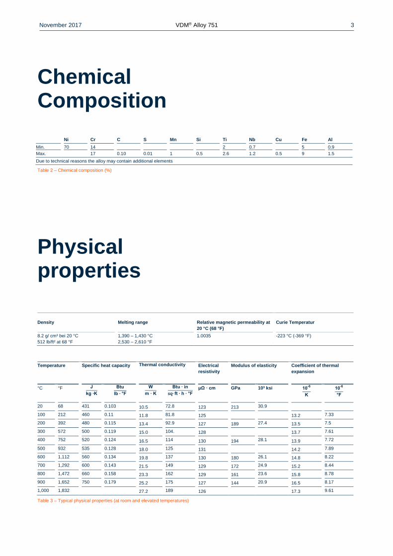
Chemical Composition
Ni Cr C S Mn Si Ti Nb Cu Fe Al
Min. 70 14 2 0.7 5 0.9
Max. 17 0.10 0.01 1 0.5 2.6 1.2 0.5 9 1.5
Due to technical reasons the alloy may contain additional elements
Table 2 – Chemical composition (%)
Physical properties
Density Melting range Relative magnetic permeability at
20 °C (68 °F)
Curie Temperatur
8.2 g/ cm³ bei 20 °C
512 lb/ft² at 68 °F
1,390 – 1,430 °C
2,530 – 2,610 °F
1.0035 -223 °C (-369 °F)
Temperature
Specific heat capacity Thermal conductivity Electrical
resistivity
Modulus of elasticity Coefficient of thermal
expansion
°C °F J
kg ∙K
Btu
lb ∙ °F
W
m · K
Btu ∙ in
sq∙ ft ∙ h ∙ °F
μΩ · cm GPa 103 ksi 10-6
K
10-6
°F
20 68 431 0.103 10.5 72.8 123 213 30.9
100 212 460 0.11 11.8 81.8 125 13.2 7.33
200 392 480 0.115 13.4 92.9 127 189 27.4 13.5 7.5
300 572 500 0.119 15.0 104. 128 13.7 7.61
400 752 520 0.124 16.5 114 130 194 28.1 13.9 7.72
500 932 535 0.128 18.0 125 131 14.2 7.89
600 1,112 560 0.134 19.8 137 130 180 26.1 14.8 8.22
700 1,292 600 0.143 21.5 149 129 172 24.9 15.2 8.44
800 1,472 660 0.158 23.3 162 129 161 23.6 15.8 8.78
900 1,652 750 0.179 25.2 175 127 144 20.9 16.5 8.17
1,000 1,832 27.2 189 126 17.3 9.61
Table 3 – Typical physical properties (at room and elevated temperatures)
November 2017 VDM® Alloy 751 4
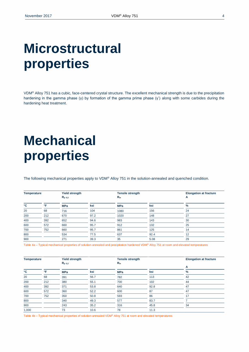
Microstructural properties
VDM® Alloy 751 has a cubic, face-centered crystal structure. The excellent mechanical strength is due to the precipitation
hardening in the gamma phase (γ) by formation of the gamma prime phase (γ’) along with some carbides during the
hardening heat treatment.
Mechanical properties
The following mechanical properties apply to VDM® Alloy 751 in the solution-annealed and quenched condition.
Temperature Yield strength
Rp 0,2
Tensile strength
Rm
Elongation at fracture
A
°C °F MPa ksi MPa ksi %
20 68 716 104 1080 156 24
200 212 670 97.2 1020 148 27
400 392 652 94.6 983 143 30
600 572 660 95.7 912 132 25
700 752 660 95.7 861 125 14
800 534 77.5 637 92.4 12
900 271 39.3 35 5.08 29
Table 4a – Typical mechanical properties of solution-annealed and precipitation hardened VDM® Alloy 751 at room and elevated temperatures
Temperature Yield strength
Rp 0,2
Tensile strength
Rm
Elongation at fracture
A
°C °F MPa ksi MPa ksi %
20 68 391 56.7 782 113 42
200 212 380 55.1 700 102 44
400 392 371 53.8 640 92.8 47
600 572 360 52.2 600 87 47
700 752 350 50.8 593 86 17
800 340 49.3 577 83.7 7
900 243 35.2 316 45.8 34
1,000 73 10.6 78 11.3
Table 4b – Typical mechanical properties of solution-annealed VDM® Alloy 751 at room and elevated temperatures
November 2017 VDM® Alloy 751 5
Corrosion resistance
VDM® Alloy 751 demonstrates an excellent corrosion resistance in high and low temperatures and the alloy furthermore
has a high resistance against stress corrosion. The resistance against oxidizing conditions is remarkably high at up to
980 °C (1,800 °F).
Applications
Due to its high strength up to 820 °C (1,508 °F) and its excellent corrosion resistance, VDM® Alloy 751 can be used in a
wide range of applications. A typical application is exhaust valves of combustion engines.
November 2017 VDM® Alloy 751 6
Fabrication and heat treatment
VDM® Alloy 751 can be easily deformed both hot and cold and can also be machined. However, for all processing, ma-
chines are required that take the mechanical properties like the high strength and characteristic work hardening rates into
account. The deformation should preferably take place in the solution-annealed condition.
Heating
It is important that the workpieces are clean and free of any contaminations before and during heat treatment. Sulfur,
phosphorus, lead and other low-melting point metals can result in material damage during the heat treatment. This type
of contamination is also contained in marking and temperature-indicating paints or pens, and also in lubricating grease,
oils, fuels and similar materials. The sulfur content of fuels must be as low as possible. Natural gas should contain less
than 0.1 wt.-% of sulfur. Heating oil with a maximum sulfur content of 0.5 wt.-% is also suitable. Electric furnaces are
preferable for their precise temperature control and a lack of contaminations from fuels. The furnace temperature should
be set between neutral and slightly oxidizing and it should not change between oxidizing and reducing. The workpieces
must not come into direct contact with flames.
Hot forming
VDM® Alloy 751 can be optimally hot formed in a temperature range between 1,200 and 980 °C (2,190 and 1,800 °F) with
subsequent rapid cooling down. For heating up, the workpieces are placed in the furnace that is heated up to the hot
forming temperature. Once the temperature has equalized, a retention time of at least 60 minutes for each 100 mm of
workpiece thickness should be observed. After this, the workpieces are removed immediately and deformed within the
specified temperature window. When falling below a temperature of 980 °C (1,800 °F), the workpiece should be heated
up as described above, as it would be too firm for further hot forming otherwise. Heat treatment after hot forming is
recommended for the optimization of mechanical properties and corrosion resistance. To ensure good mechanical prop-
erties, the last deforming step should be at least 20% and not exceed a temperature of 1,100 °C (2,012 °F).
Cold forming
VDM® Alloy 751 is cold formed ideally in the solution-annealed state. The material has a significantly higher work harden-
ing rate than austenitic stainless steels. This must be taken into account for the design and selection of forming tools and
equipment, and for the planning of forming processes.
Heat treatment
In general, the heat treatment of VDM® Alloy 751 consists of two stages:
1. Solution annealing between 980 and 1,010 °C (1,796 and 1,850 °F) for min. 0.5 hours, followed by rapid cooling
down.
2. Hardening annealing between 700 - 780 °C (1,292 - 1,436 °F) for 2-4 hours followed by air cooling.
For every heat treatment, the material should be inserted into the furnace already heated up to the annealing temperature
and the information provided in the section “Heating” should be observed.
Descaling and pickling
High-temperature materials develop a protective oxide layer in service. The necessity for descaling should therefore be
checked when placing the order. Oxides of VDM® Alloy 751 and heat tints in the area around welds adhere more strongly
than in stainless steels. Grinding using extremely fine abrasive belts or grinding discs is recommended. Heat tints caused
by grinding (grinding burns) are to be avoided. If pickling is required, the pickling times (as for all high-temperature mate-
rials) should be kept short because they can otherwise suffer from inter-crystalline corrosion attack. Furthermore, the
temperature of the pickling line must be checked. Before pickling in nitric-hydrofluoric acid mixtures, dense oxide layers
should be destroyed by blasting or grinding, or pre-treated in salt baths.
November 2017 VDM® Alloy 751 7
Machining
While VDM® Alloy 751 in the solution-annealed condition is easier to process and the strain on tools is less, better surface
quality is achieved in the hardened condition. The best results in terms of the surface quality and dimensional accuracy
of the finished product are achieved by pre-treatment before hardening and by finishing in the hardened condition. Be-
cause of the increased propensity for work hardening in comparison to low-alloy austenitic stainless steels, a lower cutting
speed should be selected and the cutting tool should stay engaged at all times. An adequate chip depth is important in
order to cut below a previously formed work-hardened zone.
Welding information
When welding nickel alloys and special stainless steels, the following information should be taken into account:
Safety
The generally applicable safety recommendations, especially for avoiding dust and smoke exposure must be observed.
Workplace
A workplace arranged separately must be provided that is specifically cordoned off from areas where C steel is being
processed. Maximum cleanliness is required, and drafts should be avoided during gas-shielded welding.
Auxiliary equipment and clothing
Clean fine leather gloves and clean working clothes must be used.
Tools and machines
Tools that have been used for other materials may not be used for nickel alloys and stainless steels. Only stainless steel
brushes may be used. Machines such as shears, punches or rollers must be fitted (e.g. with felt, cardboard, films) so that
the workpiece surfaces cannot be damaged by such equipment from iron particles being pressed in, as this can lead to
corrosion.
Edge preparation
Edge preparation should preferably be carried out using mechanical methods such as lathing, milling or planing. Abrasive
waterjet cutting or plasma cutting is also possible. In case of the latter, however, the cut edge (seam flank) must be
reworked cleanly. Careful grinding without overheating is also permissible.
Striking the arc
Striking the arc may only take place in the seam area, e.g. on the seam flanks or on an outlet piece, and not on the
component surface. Scaling areas are places that may be more susceptible to corrosion.
Included angle
Compared to C-steels, nickel alloys and special stainless steels exhibit lower thermal conductivity and greater heat ex-
pansion. Larger root openings and root gaps (1 to 3 mm) are required to meet these properties. Due to the viscosity of
the welding material (compared to standard austenites) and the tendency to shrink, included angles of 60 to 70° – as
shown in Figure 1 – have to be provided for butt welds.

November 2017 VDM® Alloy 751 8
Figure 1 – Edge preparations for welding nickel alloys
and special stainless steels
Cleaning
The basic material in the seam area (both sides) and the filler material (e.g. welding rod) should be cleaned with acetone.
Welding technique
VDM® Alloy 751 can be welded with a number of different welding techniques. If the metal shielding gas welding technique
(MSG) is applied, the impulse technique is preferable. The material should be in its solution-annealed condition for welding
and it should be free from scale, grease and markings. When welding the root, the root should be protected in the best
possible way (e.g. argon 4.6), so that the welding edge is free from oxides after welding the root. Any heat tints must be
removed, preferably using a stainless steel brush, while the welding edge is still hot.
Welding filler
VDM® FM 82 (Material no. 2.4806)
UNS N06082; AWS A5.14: ERNiCr-3;
DIN EN ISO 18274 - S Ni 6082 (NiCr20Mn3Nb)
VDM® FM 617 (Material no. 2.4627)
UNS N06617; AWS A5.14: ERNiCrCoMo-1;
DIN EN ISO 18274 - S Ni6617(NiCr22Co12Mo9)
It should be noted that the basic material (as described above) can be hardened, whereas the specified filler
materials cannot. This results in the weld metal having a lower strength than the hardened basic material VDM®
Alloy 751.
November 2017 VDM® Alloy 751 9
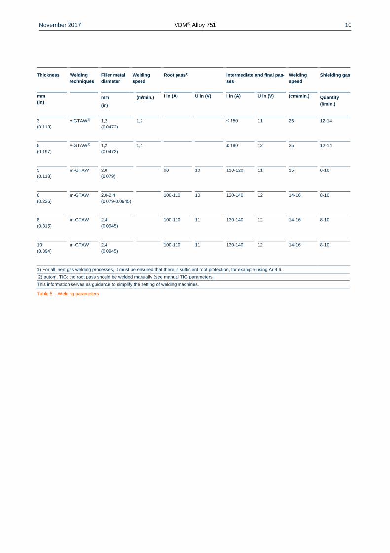
Welding parameters and influences
It must be ensured that work is carried out with a targeted heat application and low heat input as listed in the examples in
Table 5. The stringer bead technique is recommended. The interpass temperature should not exceed 100 °C. In principle,
continuous checking of welding parameters is necessary.
The section energy E can be calculated as follows:
E = U x I x 60 /v x 1000 (kJ/cm)
U = arc voltage, volts
I = welding current strength, amperes
v = welding speed, cm/minute
Post-treatment
If the work is performed optimally, brushing immediately after welding, i.e. while still warm and without additional pickling,
will result in the desired surface condition. In other words, heat tints can be removed completely. Pickling, if required or
specified, should generally be the last work step in the welding process. The information contained in the section entitled
"Descaling and pickling" must be observed. Heat treatments are normally neither required before nor after welding.
November 2017 VDM® Alloy 751 10
Thickness Welding
techniques
Filler metal
diameter
Welding
speed
Root pass1) Intermediate and final pas-
ses
Welding
speed
Shielding gas
mm
(in)
mm
(in)
(m/min.) I in (A) U in (V) I in (A) U in (V) (cm/min.) Quantity
(l/min.)
3
(0.118)
v-GTAW2) 1,2
(0.0472)
1,2 ≤ 150 11 25 12-14
5
(0.197)
v-GTAW2) 1,2
(0.0472)
1,4 ≤ 180 12 25 12-14
3
(0.118)
m-GTAW 2,0
(0.079)
90 10 110-120 11 15 8-10
6
(0.236)
m-GTAW 2,0-2,4
(0.079-0.0945)
100-110 10 120-140 12 14-16 8-10
8
(0.315)
m-GTAW 2.4
(0.0945)
100-110 11 130-140 12 14-16 8-10
10
(0.394)
m-GTAW 2.4
(0.0945)
100-110 11 130-140 12 14-16 8-10
1) For all inert gas welding processes, it must be ensured that there is sufficient root protection, for example using Ar 4.6.
2) autom. TIG: the root pass should be welded manually (see manual TIG parameters)
This information serves as guidance to simplify the setting of welding machines.
Table 5 - Welding parameters
November 2017 VDM® Alloy 751 11
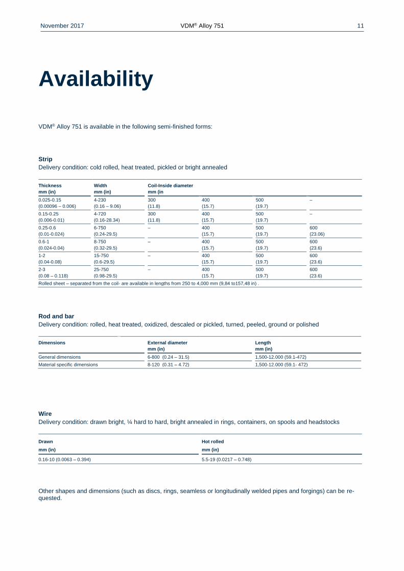
Availability
VDM® Alloy 751 is available in the following semi-finished forms:
Strip
Delivery condition: cold rolled, heat treated, pickled or bright annealed
Thickness
mm (in)
Width
mm (in)
Coil-Inside diameter
mm (in
0.025-0.15
(0.00096 – 0.006)
4-230
(0.16 – 9.06)
300
(11.8)
400
(15.7)
500
(19.7)
–
0.15-0.25
(0.006-0.01)
4-720
(0.16-28.34)
300
(11.8)
400
(15.7)
500
(19.7)
–
0.25-0.6
(0.01-0.024)
6-750
(0.24-29.5)
– 400
(15.7)
500
(19.7)
600
(23.06)
0.6-1
(0.024-0.04)
8-750
(0.32-29.5)
– 400
(15.7)
500
(19.7)
600
(23.6)
1-2
(0.04-0.08)
15-750
(0.6-29.5)
– 400
(15.7)
500
(19.7)
600
(23.6)
2-3
(0.08 – 0.118)
25-750
(0.98-29.5)
– 400
(15.7)
500
(19.7)
600
(23.6)
Rolled sheet – separated from the coil- are available in lengths from 250 to 4,000 mm (9,84 to157,48 in) .
Rod and bar
Delivery condition: rolled, heat treated, oxidized, descaled or pickled, turned, peeled, ground or polished
Dimensions External diameter
mm (in)
Length
mm (in)
General dimensions 6-800 (0.24 – 31.5) 1,500-12.000 (59.1-472)
Material specific dimensions 8-120 (0.31 – 4.72) 1,500-12.000 (59.1- 472)
Wire
Delivery condition: drawn bright, ¼ hard to hard, bright annealed in rings, containers, on spools and headstocks
Drawn
mm (in)
Hot rolled
mm (in)
0.16-10 (0.0063 – 0.394) 5.5-19 (0.0217 – 0.748)
Other shapes and dimensions (such as discs, rings, seamless or longitudinally welded pipes and forgings) can be re-quested.
November 2017 VDM® Alloy 751 12
30 November 2017
Publisher
VDM Metals International GmbH
Plettenberger Straße 2
58791 Werdohl
Germany
Disclaimer
All information contained in this data sheet is based on the results of research and development work carried out by VDM
Metals International GmbH and the data contained in the specifications and standards listed available at the time of print-
ing. The information does not represent a guarantee of specific properties. VDM Metals reserves the right to change
information without notice. All information contained in this data sheet is compiled to the best of our knowledge and is
provided without liability. Deliveries and services are subject exclusively to the relevant contractual conditions and the
General Terms and Conditions issued by VDM Metals. Use of the most up-to-date version of this data sheet is the re-
sponsibility of the customer.
Imprint
VDM Metals International GmbH
Plettenberger Straße 2
58791 Werdohl
Germany
Phone +49 (0)2392 55 0
Fax +49 (0)2392 55 22 17
www.vdm-metals.com