Embed Size (px)
DESCRIPTION
best report
Citation preview
7/18/2019 Night Vision Technology Seminar Report PDF 130805071844 Phpapp01
http://slidepdf.com/reader/full/night-vision-technology-seminar-report-pdf-130805071844-phpapp01 1/31
Night Vision Technology
Introduction
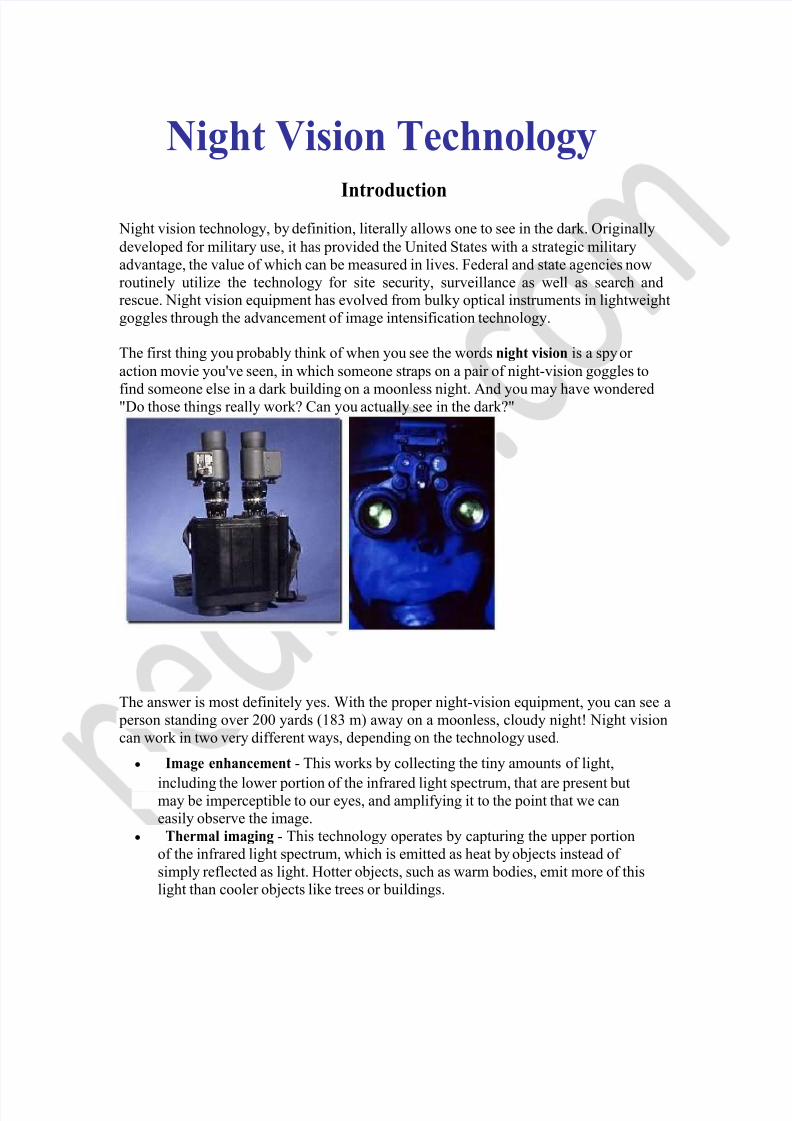
Night vision technology, by definition, literally allows one to see in the dark. Originally developed for military use, it has provided the United States with a strategic military advantage, the value of which can be measured in lives. Federal and state agencies now routinely utilize the technology for site security, surveillance as well as search and rescue. Night vision equipment has evolved from bulky optical instruments in lightweight goggles through the advancement of image intensification technology. The first thing you probably think of when you see the words night vision is a spy or action movie you've seen, in which someone straps on a pair of night-vision goggles to find
someone
else
in
a dark
building
on
a moonless
night.
And
you
may
have
wondered
"Do those things really work? Can you actually see in the dark?"
The answer is most definitely yes. With the proper night-vision equipment, you can see a person standing over 200 yards (183 m) away on a moonless, cloudy night! Night vision can work in two very different ways, depending on the technology used.
Image enhancement - This works by collecting the tiny amounts of light, including the lower portion of the infrared light spectrum, that are present but may be imperceptible to our eyes, and amplifying it to the point that we can easily observe the image.
Thermal imaging - This technology operates by capturing the upper portion of the infrared light spectrum, which is emitted as heat by objects instead of simply reflected as light. Hotter objects, such as warm bodies, emit more of this light than cooler objects like trees or buildings.
7/18/2019 Night Vision Technology Seminar Report PDF 130805071844 Phpapp01
http://slidepdf.com/reader/full/night-vision-technology-seminar-report-pdf-130805071844-phpapp01 2/31
In this article, you will learn about the two major night-vision technologies. We'll also discuss the various types of night-vision equipment and applications. But first, let's talk about infrared light.
The Basics
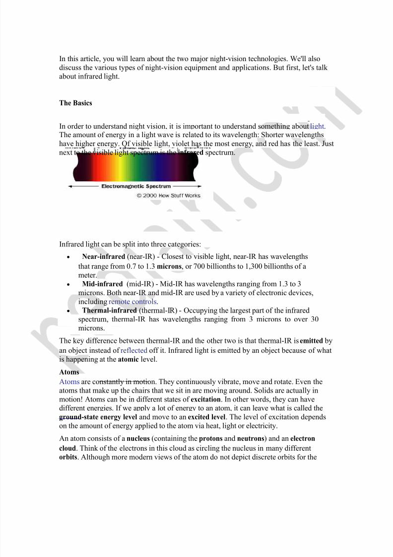
In order to understand night vision, it is important to understand something about light. The amount of energy in a light wave is related to its wavelength: Shorter wavelengths have higher energy. Of visible light, violet has the most energy, and red has the least. Just next to the visible light spectrum is the infrared spectrum.
Infrared light can be split into three categories: Near-infrared (near-IR) - Closest to visible light, near-IR has wavelengths
that range from 0.7 to 1.3 microns, or 700 billionths to 1,300 billionths of a meter.
Mid-infrared (mid-IR) - Mid-IR has wavelengths ranging from 1.3 to 3 microns. Both near-IR and mid-IR are used by a variety of electronic devices, including remote controls.
Thermal-infrared (thermal-IR) - Occupying the largest part of the infrared spectrum, thermal-IR has wavelengths ranging from 3 microns to over 30 microns.
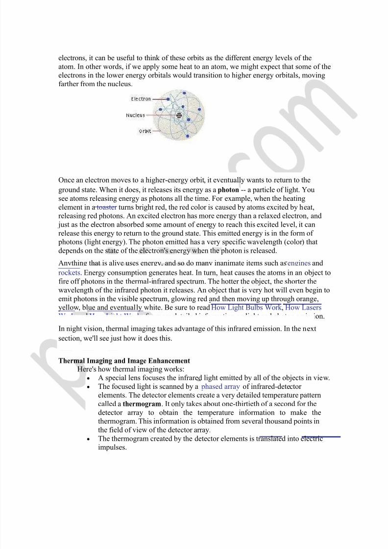
The key difference between thermal-IR and the other two is that thermal-IR is emitted by an object instead of reflected off it. Infrared light is emitted by an object because of what is happening at the atomic level. Atoms Atoms are constantly in motion. They continuously vibrate, move and rotate. Even the atoms that make up the chairs that we sit in are moving around. Solids are actually in motion! Atoms can be in different states of excitation. In other words, they can have different energies. If we apply a lot of energy to an atom, it can leave what is called the ground-state energy level and move to an excited level. The level of excitation depends on the amount of energy applied to the atom via heat, light or electricity. An atom consists of a nucleus (containing the protons and neutrons) and an electron cloud. Think of the electrons in this cloud as circling the nucleus in many different orbits. Although more modern views of the atom do not depict discrete orbits for the
7/18/2019 Night Vision Technology Seminar Report PDF 130805071844 Phpapp01
http://slidepdf.com/reader/full/night-vision-technology-seminar-report-pdf-130805071844-phpapp01 3/31
electrons, it can be useful to think of these orbits as the different energy levels of the atom. In other words, if we apply some heat to an atom, we might expect that some of the electrons in the lower energy orbitals would transition to higher energy orbitals, moving farther from the nucleus.
Once an electron moves to a higher-energy orbit, it eventually wants to return to the ground state. When it does, it releases its energy as a
photon
-- a particle of light. You
see atoms releasing energy as photons all the time. For example, when the heating element in a toaster turns bright red, the red color is caused by atoms excited by heat, releasing red photons. An excited electron has more energy than a relaxed electron, and just as the electron absorbed some amount of energy to reach this excited level, it can release this energy to return to the ground state. This emitted energy is in the form of photons (light energy). The photon emitted has a very specific wavelength (color) that depends on the state of the electron's energy when the photon is released. Anything that is alive uses energy, and so do many inanimate items such as engines and rockets. Energy consumption generates heat. In turn, heat causes the atoms in an object to fire off photons in the thermal-infrared spectrum. The hotter the object, the shorter the wavelength of the infrared photon it releases. An object that is very hot will even begin to emit photons in the visible spectrum, glowing red and then moving up through orange, yellow, blue and eventually white. Be sure to read How Light Bulbs Work , How Lasers Work and How Light Works for more detailed information on light and photon emission. In night vision, thermal imaging takes advantage of this infrared emission. In the next section, we'll see just how it does this.
Thermal Imaging and Image Enhancement Here's how thermal imaging works:
A special lens focuses the infrared light emitted by all of the objects in view. The focused light is scanned by a phased array of infrared-detector
elements. The detector elements create a very detailed temperature pattern called a thermogram. It only takes about one-thirtieth of a second for the detector array to obtain the temperature information to make the thermogram. This information is obtained from several thousand points in the field of view of the detector array.
The thermogram created by the detector elements is translated into electric impulses.
7/18/2019 Night Vision Technology Seminar Report PDF 130805071844 Phpapp01
http://slidepdf.com/reader/full/night-vision-technology-seminar-report-pdf-130805071844-phpapp01 4/31
The impulses are sent to a signal-processing unit, a circuit board with a dedicated chip that translates the information from the elements into data for the display.
The signal-processing unit sends the information to the display, where it appears
as
various
colors
depending
on
the
intensity
of
the
infrared
emission. The combination of all the impulses from all of the elements creates the image.
Image courtesy of Infrared, Inc. The basic components of a thermal-imaging system
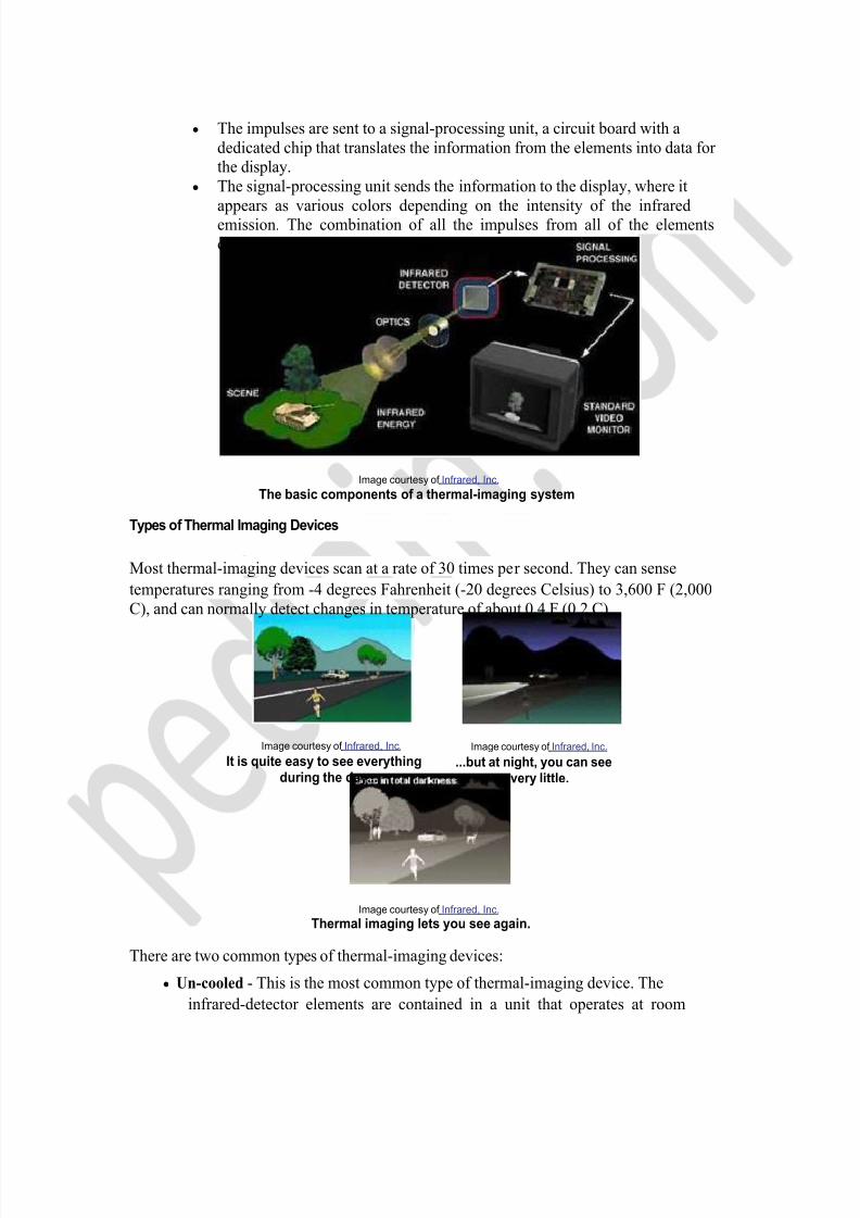
Types of Thermal Imaging Devices Most thermal-imaging devices scan at a rate of 30 times per second. They can sense temperatures ranging from -4 degrees Fahrenheit (-20 degrees Celsius) to 3,600 F (2,000 C), and can normally detect changes in temperature of about 0.4 F (0.2 C).
Image courtesy of Infrared, Inc. It is quite easy to see everything
during the day... Image courtesy of Infrared, Inc.
...but at night, you can see very little.
Image courtesy of Infrared, Inc. Thermal imaging lets you see again.
There are two common types of thermal-imaging devices: Un-cooled - This is the most common type of thermal-imaging device. The
infrared-detector elements are contained in a unit that operates at room
7/18/2019 Night Vision Technology Seminar Report PDF 130805071844 Phpapp01
http://slidepdf.com/reader/full/night-vision-technology-seminar-report-pdf-130805071844-phpapp01 5/31
temperature. This type of system is completely quiet, activates immediately and has the battery built right in.
Cryogenically cooled - More expensive and more susceptible to damage from rugged use, these systems have the elements sealed inside a container that cools
them
to
below
32
F
(zero
C).
The
advantage
of
such
a system
is
the
incredible resolution and sensitivity that result from cooling the elements. Cryogenically-cooled systems can "see" a difference as small as 0.2 F (0.1 C) from more than 1,000 ft (300 m) away, which is enough to tell if a person is holding a gun at that distance!
While thermal imaging is great for detecting people or working in near-absolute darkness, most night-vision equipment uses image-enhancement technology. Image Enhancement
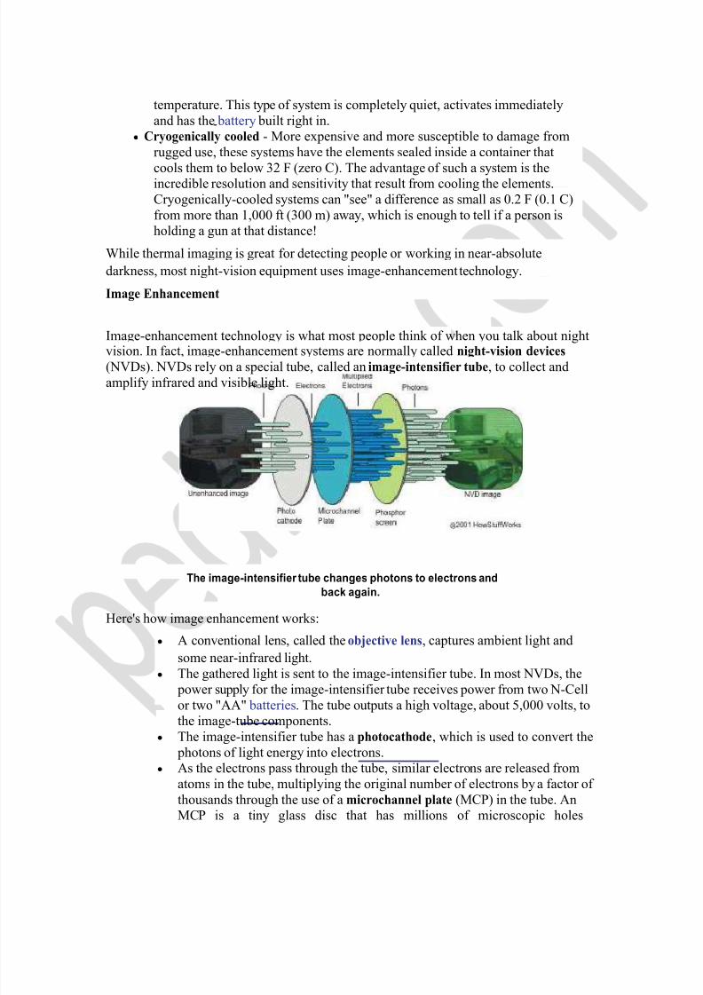
Image-enhancement technology is what most people think of when you talk about night vision. In fact, image-enhancement systems are normally called night-vision devices (NVDs). NVDs rely on a special tube, called an image-intensifier tube, to collect and amplify infrared and visible light.
The image-intensifier tube changes photons to electrons and back again.
Here's how image enhancement works: A conventional lens, called the objective lens, captures ambient light and
some near-infrared light. The gathered light is sent to the image-intensifier tube. In most NVDs, the
power supply for the image-intensifier tube receives power from two N-Cell or two "AA" batteries. The tube outputs a high voltage, about 5,000 volts, to the image-tube components.
The image-intensifier tube has a photocathode, which is used to convert the photons of light energy into electrons.
As the electrons pass through the tube, similar electrons are released from atoms in the tube, multiplying the original number of electrons by a factor of thousands through the use of a microchannel plate (MCP) in the tube. An MCP is a tiny glass disc that has millions of microscopic holes
7/18/2019 Night Vision Technology Seminar Report PDF 130805071844 Phpapp01
http://slidepdf.com/reader/full/night-vision-technology-seminar-report-pdf-130805071844-phpapp01 6/31
(microchannels) in it, made using fiber-optic technology. The MCP is contained in a vacuum and has metal electrodes on either side of the disc. Each channel is about 45 times longer than it is wide, and it works as an electron multiplier.
When the electrons from the photo cathode hit the first electrode of the MCP, they are accelerated into the glass microchannels by the 5,000-V bursts being sent between the electrode pair. As electrons pass through the microchannels, they cause thousands of other electrons to be released in each channel using a
process called cascaded secondary emission. Basically, the original electrons collide with the side of the channel, exciting atoms and causing other electrons to be released. These new electrons also collide with other atoms, creating a chain reaction that results in thousands of electrons leaving the channel where only a few entered. An interesting fact is that the microchannels in the MCP are created at a slight angle (about a 5-degree to 8-degree bias) to encourage electron collisions and reduce both ion and direct-light feedback from the
phosphors on the output side. At the end of the image-
intensifier tube, the electrons hit a screen coated with phosphors. These electrons maintain their
position in relation to the channel they passed through, which
provides a perfect image since the electrons stay in the same alignment as the original photons. The energy of the electrons causes the phosphors to reach an
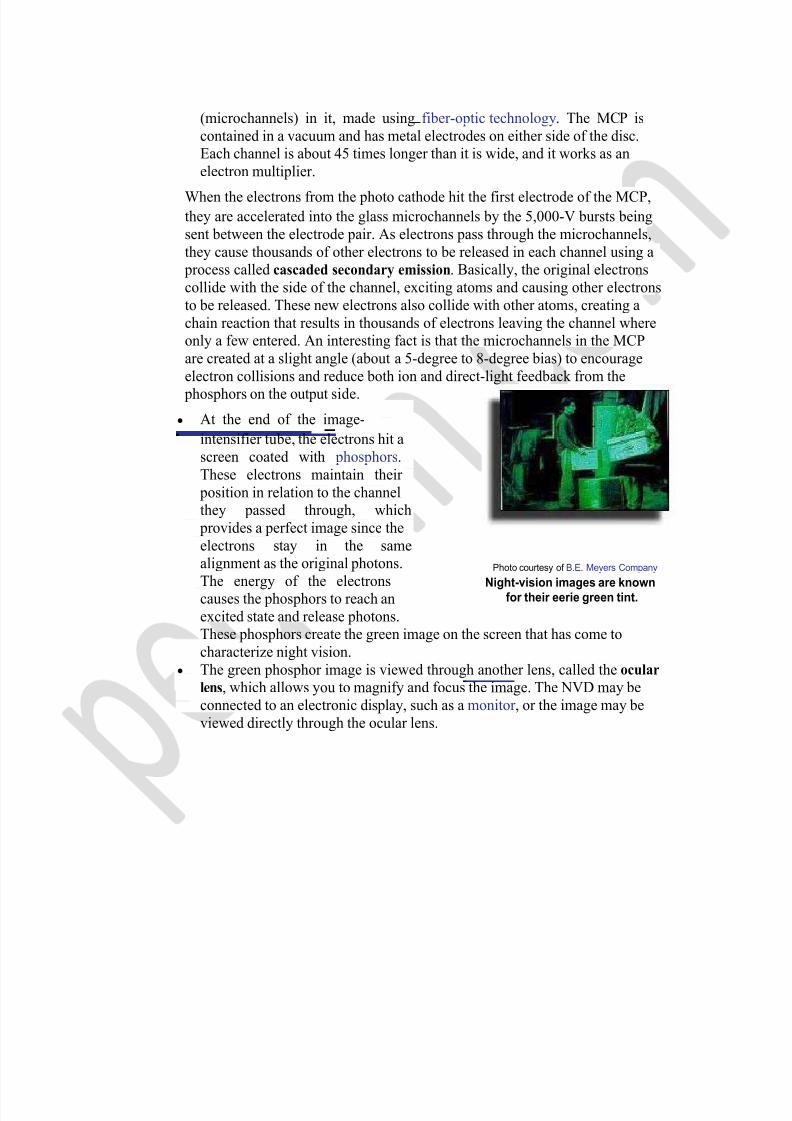
Photo courtesy of B.E. Meyers Company Night-vision images are known
for their eerie green tint. excited state and release photons. These phosphors create the green image on the screen that has come to characterize night vision.
The green phosphor image is viewed through another lens, called the ocular lens, which allows you to magnify and focus the image. The NVD may be connected to an electronic display, such as a monitor , or the image may be viewed directly through the ocular lens.
7/18/2019 Night Vision Technology Seminar Report PDF 130805071844 Phpapp01
http://slidepdf.com/reader/full/night-vision-technology-seminar-report-pdf-130805071844-phpapp01 7/31
Generations
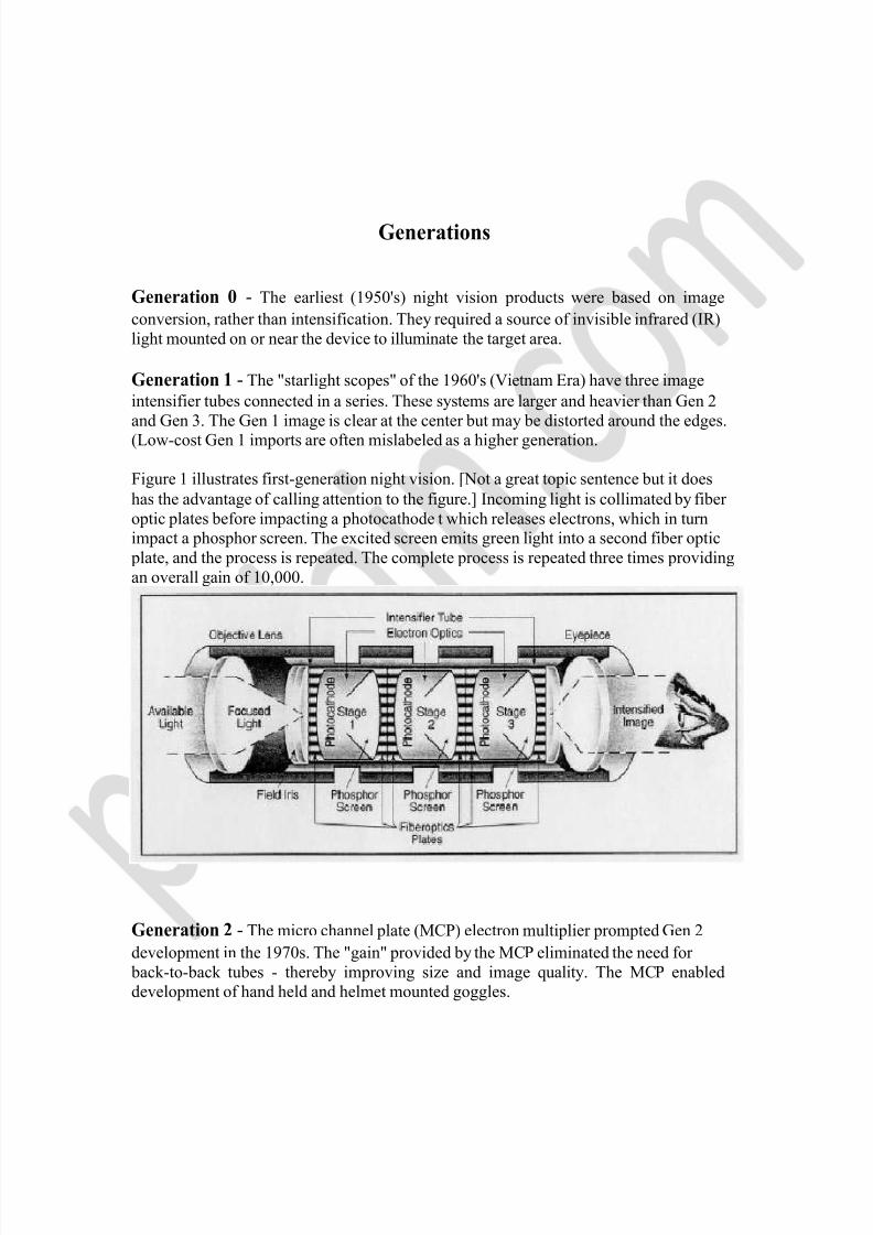
Generation 0 - The earliest (1950's) night vision products were based on image conversion, rather than intensification. They required a source of invisible infrared (IR) light mounted on or near the device to illuminate the target area. Generation 1 - The "starlight scopes" of the 1960's (Vietnam Era) have three image intensifier tubes connected in a series. These systems are larger and heavier than Gen 2 and Gen 3. The Gen 1 image is clear at the center but may be distorted around the edges. (Low-cost Gen 1 imports are often mislabeled as a higher generation. Figure 1 illustrates first-generation night vision. [Not a great topic sentence but it does has the advantage of calling attention to the figure.] Incoming light is collimated by fiber optic plates before impacting a photocathode t which releases electrons, which in turn impact a phosphor screen. The excited screen emits green light into a second fiber optic plate, and the process is repeated. The complete process is repeated three times providing an overall gain of 10,000.
Generation 2 - The micro channel plate (MCP) electron multiplier prompted Gen 2 development in the 1970s. The "gain" provided by the MCP eliminated the need for back-to-back tubes - thereby improving size and image quality. The MCP enabled development of hand held and helmet mounted goggles.
7/18/2019 Night Vision Technology Seminar Report PDF 130805071844 Phpapp01
http://slidepdf.com/reader/full/night-vision-technology-seminar-report-pdf-130805071844-phpapp01 8/31
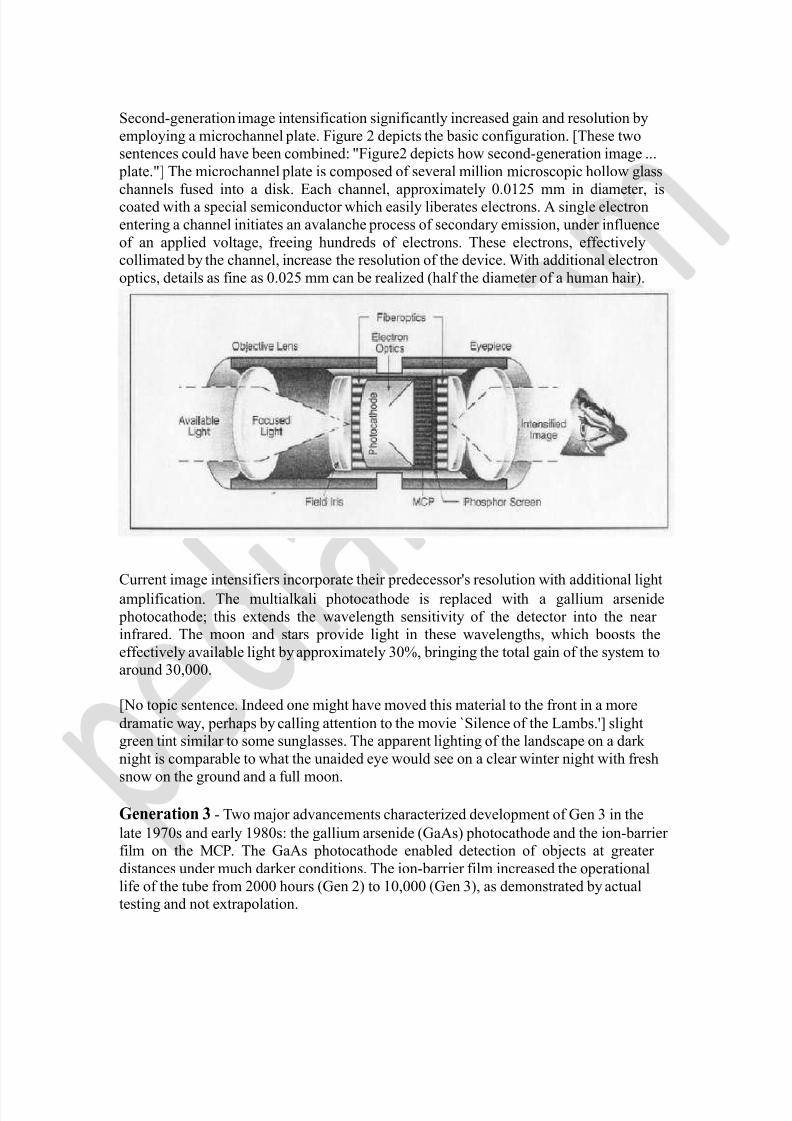
Second-generation image intensification significantly increased gain and resolution by employing a microchannel plate. Figure 2 depicts the basic configuration. [These two sentences could have been combined: "Figure2 depicts how second-generation image ... plate."] The microchannel plate is composed of several million microscopic hollow glass channels
fused
into
a disk.
Each
channel,
approximately
0.0125
mm
in
diameter,
is
coated with a special semiconductor which easily liberates electrons. A single electron entering a channel initiates an avalanche process of secondary emission, under influence of an applied voltage, freeing hundreds of electrons. These electrons, effectively collimated by the channel, increase the resolution of the device. With additional electron optics, details as fine as 0.025 mm can be realized (half the diameter of a human hair).
Current image intensifiers incorporate their predecessor's resolution with additional light amplification. The multialkali photocathode is replaced with a gallium arsenide photocathode; this extends the wavelength sensitivity of the detector into the near infrared. The moon and stars provide light in these wavelengths, which boosts the effectively available light by approximately 30%, bringing the total gain of the system to around 30,000. [No topic sentence. Indeed one might have moved this material to the front in a more dramatic way, perhaps by calling attention to the movie `Silence of the Lambs.'] slight green tint similar to some sunglasses. The apparent lighting of the landscape on a dark night is comparable to what the unaided eye would see on a clear winter night with fresh snow on the ground and a full moon. Generation 3 - Two major advancements characterized development of Gen 3 in the late 1970s and early 1980s: the gallium arsenide (GaAs) photocathode and the ion-barrier film on the MCP. The GaAs photocathode enabled detection of objects at greater distances under much darker conditions. The ion-barrier film increased the operational life of the tube from 2000 hours (Gen 2) to 10,000 (Gen 3), as demonstrated by actual testing and not extrapolation.
7/18/2019 Night Vision Technology Seminar Report PDF 130805071844 Phpapp01
http://slidepdf.com/reader/full/night-vision-technology-seminar-report-pdf-130805071844-phpapp01 9/31
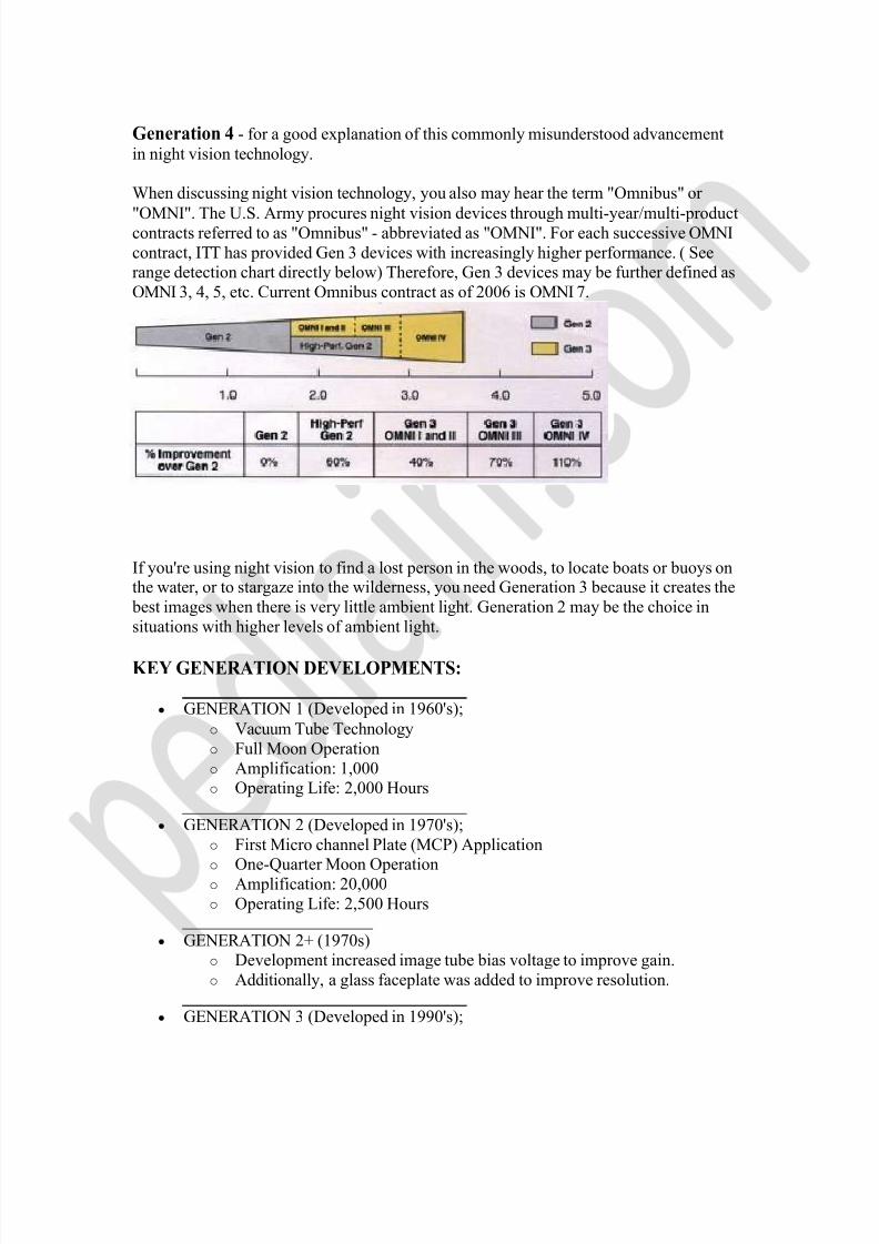
Generation 4 - for a good explanation of this commonly misunderstood advancement in night vision technology. When discussing night vision technology, you also may hear the term "Omnibus" or "OMNI". The U.S. Army procures night vision devices through multi-year/multi-product contracts referred to as "Omnibus" - abbreviated as "OMNI". For each successive OMNI contract, ITT has provided Gen 3 devices with increasingly higher performance. ( See range detection chart directly below) Therefore, Gen 3 devices may be further defined as OMNI 3, 4, 5, etc. Current Omnibus contract as of 2006 is OMNI 7.
If you're using night vision to find a lost person in the woods, to locate boats or buoys on the water, or to stargaze into the wilderness, you need Generation 3 because it creates the best images when there is very little ambient light. Generation 2 may be the choice in situations with higher levels of ambient light. KEY GENERATION DEVELOPMENTS:
GENERATION 1 (Developed in 1960's); o Vacuum Tube Technology o Full Moon Operation o Amplification: 1,000 o Operating Life: 2,000 Hours
GENERATION 2 (Developed in 1970's); o First Micro channel Plate (MCP) Application o
One-Quarter Moon
Operation
o Amplification: 20,000 o Operating Life: 2,500 Hours
GENERATION 2+ (1970s) o Development increased image tube bias voltage to improve gain. o Additionally, a glass faceplate was added to improve resolution.
GENERATION 3 (Developed in 1990's);
7/18/2019 Night Vision Technology Seminar Report PDF 130805071844 Phpapp01
http://slidepdf.com/reader/full/night-vision-technology-seminar-report-pdf-130805071844-phpapp01 10/31
o Improved MCP & Photocathode o Starlight Operation o Amplification: 40,000 o Operating Life: 10,000 Hour
GENERATION 3 Enhanced (2000's); o Improvements in the photocathode and MCP resulted in increased gain
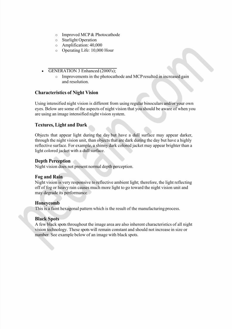
and resolution. Characteristics of Night Vision Using intensified night vision is different from using regular binoculars and/or your own eyes. Below are some of the aspects of night vision that you should be aware of when you are using an image intensified night vision system. Textures, Light and Dark Objects that appear light during the day but have a dull surface may appear darker, through the night vision unit, than objects that are dark during the day but have a highly reflective surface. For example, a shinny dark colored jacket may appear brighter than a light colored jacket with a dull surface. Depth Perception Night vision does not present normal depth perception. Fog and Rain Night vision is very responsive to reflective ambient light; therefore, the light reflecting off of fog or heavy rain causes much more light to go toward the night vision unit and may degrade its performance. Honeycomb This is a faint hexagonal pattern which is the result of the manufacturing process. Black Spots A few black spots throughout the image area are also inherent characteristics of all night vision technology. These spots will remain constant and should not increase in size or number. See example below of an image with black spots.
7/18/2019 Night Vision Technology Seminar Report PDF 130805071844 Phpapp01
http://slidepdf.com/reader/full/night-vision-technology-seminar-report-pdf-130805071844-phpapp01 11/31
* Do not be concerned if you see this feature-it is an inherent characteristic found in light amplification night vision systems that incorporate a microchannel plate in the intensifier.
Equipment and Applications Night-vision equipment can be split into three broad categories:
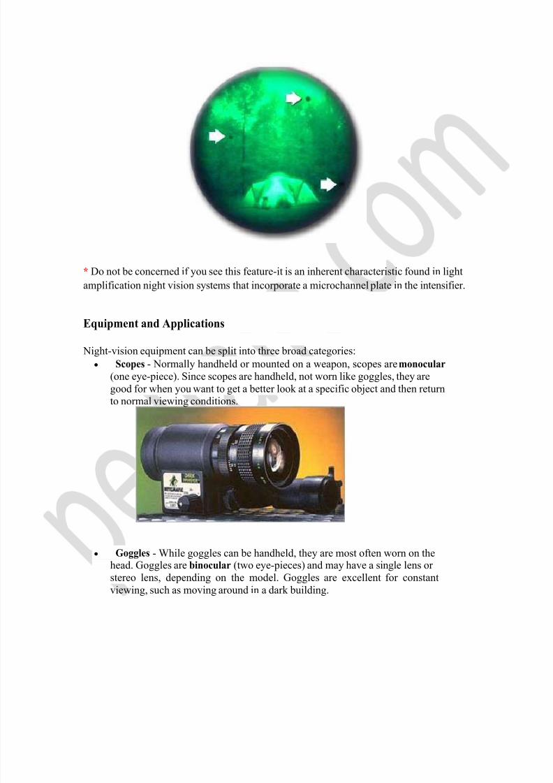
Scopes - Normally handheld or mounted on a weapon, scopes are monocular (one eye-piece). Since scopes are handheld, not worn like goggles, they are good for when you want to get a better look at a specific object and then return to normal viewing conditions.
Goggles - While goggles can be handheld, they are most often worn on the head. Goggles are binocular (two eye-pieces) and may have a single lens or stereo lens, depending on the model. Goggles are excellent for constant viewing, such as moving around in a dark building.
7/18/2019 Night Vision Technology Seminar Report PDF 130805071844 Phpapp01
http://slidepdf.com/reader/full/night-vision-technology-seminar-report-pdf-130805071844-phpapp01 12/31
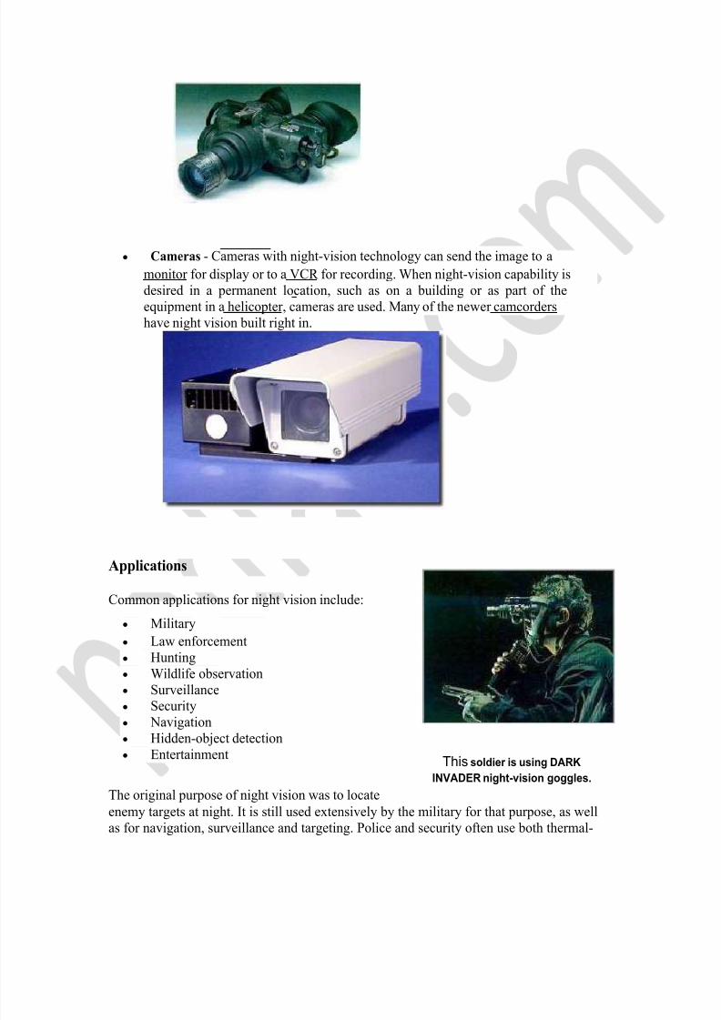
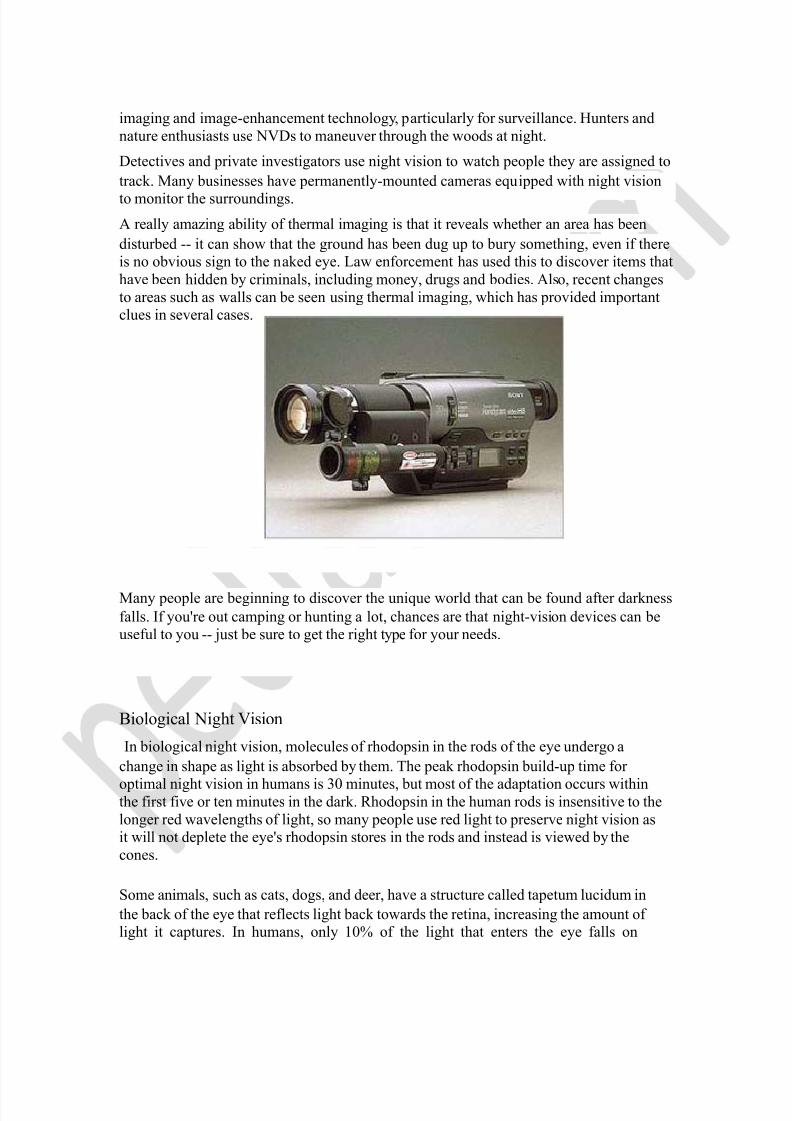
Cameras - Cameras with night-vision technology can send the image to a monitor for display or to a VCR for recording. When night-vision capability is desired in a permanent location, such as on a building or as part of the equipment in a helicopter, cameras are used. Many of the newer camcorders have night vision built right in.
Applications Common applications for night vision include:
Military Law enforcement Hunting Wildlife observation Surveillance Security Navigation Hidden-object detection Entertainment
This soldier is using DARK INVADER night-vision goggles.
The original purpose of night vision was to locate enemy targets at night. It is still used extensively by the military for that purpose, as well as for navigation, surveillance and targeting. Police and security often use both thermal-
7/18/2019 Night Vision Technology Seminar Report PDF 130805071844 Phpapp01
http://slidepdf.com/reader/full/night-vision-technology-seminar-report-pdf-130805071844-phpapp01 13/31
imaging and image-enhancement technology, particularly for surveillance. Hunters and nature enthusiasts use NVDs to maneuver through the woods at night. Detectives and private investigators use night vision to watch people they are assigned to track. Many businesses have permanently-mounted cameras equipped with night vision to monitor the surroundings. A really amazing ability of thermal imaging is that it reveals whether an area has been disturbed -- it can show that the ground has been dug up to bury something, even if there is no obvious sign to the naked eye. Law enforcement has used this to discover items that have been hidden by criminals, including money, drugs and bodies. Also, recent changes to areas such as walls can be seen using thermal imaging, which has provided important clues in several cases.
Many people are beginning to discover the unique world that can be found after darkness falls. If you're out camping or hunting a lot, chances are that night-vision devices can be useful to you -- just be sure to get the right type for your needs.
Biological Night Vision In biological night vision, molecules of rhodopsin in the rods of the eye undergo a
change in shape as light is absorbed by them. The peak rhodopsin build-up time for optimal night vision in humans is 30 minutes, but most of the adaptation occurs within the first five or ten minutes in the dark. Rhodopsin in the human rods is insensitive to the longer red wavelengths of light, so many people use red light to preserve night vision as it will not deplete the eye's rhodopsin stores in the rods and instead is viewed by the cones. Some animals, such as cats, dogs, and deer, have a structure called tapetum lucidum in the back of the eye that reflects light back towards the retina, increasing the amount of light it captures. In humans, only 10% of the light that enters the eye falls on
7/18/2019 Night Vision Technology Seminar Report PDF 130805071844 Phpapp01
http://slidepdf.com/reader/full/night-vision-technology-seminar-report-pdf-130805071844-phpapp01 14/31
photosensitive parts of the retina. Their ability to see in low light levels may be similar to what humans see when using first or perhaps second generation image intensifiers.
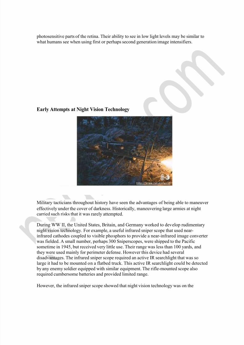
Early Attempts at Night Vision Technology
Military tacticians throughout history have seen the advantages of being able to maneuver effectively under the cover of darkness. Historically, maneuvering large armies at night carried such risks that it was rarely attempted. During WW II, the United States, Britain, and Germany worked to develop rudimentary night vision technology. For example, a useful infrared sniper scope that used near- infrared cathodes coupled to visible phosphors to provide a near-infrared image converter was fielded. A small number, perhaps 300 Sniperscopes, were shipped to the Pacific sometime in 1945, but received very little use. Their range was less than 100 yards, and they were used mainly for perimeter defense. However this device had several disadvantages. The infrared sniper scope required an active IR searchlight that was so large it had to be mounted on a flatbed truck. This active IR searchlight could be detected by any enemy soldier equipped with similar equipment. The rifle-mounted scope also required cumbersome batteries and provided limited range. However, the infrared sniper scope showed that night vision technology was on the
7/18/2019 Night Vision Technology Seminar Report PDF 130805071844 Phpapp01
http://slidepdf.com/reader/full/night-vision-technology-seminar-report-pdf-130805071844-phpapp01 15/31
horizon. Military leaders immediately saw many uses for this technology beyond sniping at the enemy under cover of darkness. An army equipped with night vision goggles, helmets, and weapons sights would be able to operate 24 hours a day. The Army Corps of Engineers, for example, would be able to build bridges and repair roads at night providing a measure of safety from airborne attack. The next challenge in night vision technology would be the development of passive systems that did not require IR searchlights that might give away a soldier's position to the enemy.
Application of Night Vision:- Automatic Brightness Control (ABC) An electronic feature that automatically reduces voltages to the microchannel plate to keep the image intensifier's brightness within optimal limits and protect the tube. The effect of this can be seen when rapidly changing from low-light to high-light conditions; the image gets brighter and then, after a momentary delay, suddenly dims to a constant level. Auto-Gated Power Supply When the power supply is "auto-gated," it means the system is turning itself on and off at a very rapid rate. This, combined with a thin film attached to the microchannel plate (an ion barrier) reduces blooming. While "blooming" can be noticeably less on systems with a thin film layer, systems with thicker film layers can be perfectly acceptable depending on the end user's application. Deciding which night vision goggle is better should not be based solely on blooming.
Black Spots These are common blemishes in the image intensifier of the NVD or can be dirt or debris between the lenses of the NVG. Black spots that are in the image intensifier do not affect the performance or reliability of a night vision device and are inherent in the manufacturing
processes.
Every
night
vision
image
intensifier
tube
is
different.
They
are
like diamonds. See image to the right. Binocular Viewing a single image source with both eyes (example: watching a television set). Binocular Viewing a scene through two channels; i.e. one channel per eye.

7/18/2019 Night Vision Technology Seminar Report PDF 130805071844 Phpapp01
http://slidepdf.com/reader/full/night-vision-technology-seminar-report-pdf-130805071844-phpapp01 16/31
Blooming Loss of the entire night vision image, parts of it, or small parts of it, due to intensifier tube overloading by a bright light source. Also, known as a "halo" effect, when the viewer sees a "halo" effect around visible light sources. When such a bright light source comes
into
the
night
vision
device's
view,
the
entire
night
vision
scene,
or
parts
of
it,
become much brighter, "whiting out" objects within the field of view. Blooming is common in Generation 0 and 1 devices. The lights in the image to the right would be considered to be "blooming". Bright-Source Protection (BSP) - High-Light Cut-Off An electronic function that reduces the voltage to the photocathode when the night vision device is exposed to bright light sources such as room lights or car lights. BSP protects the image tube from damage and enhances its life; however, it also has the effect of lowering resolution when functioning. Boresighting The alignment of a weapon aiming device to the bore of the weapon. See also Zeroing. C-Mount A standard still and video camera lens thread size for mounting to the body of a camera. Usually 1/2" or 3/4" in diameter. COMSPEC (Commercial Specification) A term used to describe image tube quality, testing and inspection done by the original equipment manufacturer (OEM). Chicken Wire An irregular pattern of dark thin lines in the field of view either throughout the image area or in parts of the image area. Under the worst-case condition, these lines wwill form hexagonal or square wave-shape lines. Daylight Lens Cover Usually made of soft plastic or rubber with a pinhole that allows a small amount of light to enter the objective lens of a night vision device. This should be used for training purposes only, and is not recommended for an extended period of time. Daylight Training Filter A glass filter assembly designed to fit over the objective lens of a night vision device. The filter reduces light input to a safe (night-time) level, allowing safe extended daytime use of the night vision device. Diopter The unit of measure used to define eye correction or the refractive power of a lens. Usually, adjustments to an optical eyepiece accomodate for differences in individual eyesight. Most ITT systems provide a +2 to -6 diopter range.
7/18/2019 Night Vision Technology Seminar Report PDF 130805071844 Phpapp01
http://slidepdf.com/reader/full/night-vision-technology-seminar-report-pdf-130805071844-phpapp01 17/31
Distortion There are two types of distortion found in night vision systems. One type is caused by the design of the optics, or image intensifier tube, and is classical optical distortion. The other type is associated with manufacturing flaws in the fiber optics used in the image intensifier
tube.
Classical Optical Distortion: Classical optical distortion occurs when the design of the optics or image intensifier tube causes straight lines at the edge of the field of view to curve inward or outward. This curving of straight lines at the edge will cause a square grid pattern to start to look like a pincushion or barrel. This distortion is the same for all systems with the same model number. Good optical design normally makes this distortion so low that the typical user will not see the curving of the lines. Fiber Optics Manufacturing Distortions: Two types of fiber optics distortions are most significant to night vision devices: S- distortion and shear distortion:
o S-Distortion: Results from the twisting operation in manufacturing fiber- optic inverters. Usually S-distortion is very small and is difficult to detect with the unaided eye.
o Shear Distortion: Can occur in any image tube that use fiber-optic bundles for the phosphor screen. It appears as a cleavage or dislocation in a straight line viewed in the image area, as though the line was "sheared".
Equivalent Background Illumination (EBI) This is the amount of light you see through a night vision device when an image tube is turned on but no light is on the photocathode. EBI is affected by temperature; the warmer the night vision device, the brighter the background illumination. EBI is measured in lumens per square centimeter (lm/cm2). The lower the value the better. The EBI level determines the lowest light level at which an image can be detected. Below this light level, objects will be masked by the EBI. Emission Point A steady or fluctuating pinpoint of bright light in the image area that does not go away when all light is blocked from the objective lens. The position of an emission point within the field of view will not move. If an emission point disappears or is only faintly visible when viewing under brighter nighttime conditions, it is not indicative of a problem. If the emission point remains bright under all lighting conditions, the system needs to be repaired. Do not confuse an emission point with a point of light source in the scene being viewed.
7/18/2019 Night Vision Technology Seminar Report PDF 130805071844 Phpapp01
http://slidepdf.com/reader/full/night-vision-technology-seminar-report-pdf-130805071844-phpapp01 18/31
Eye Relief The distance a person's eyes must be from the last element of an eyepiece in order to achieve the optimal image area.
Field-of-View The diameter of the imaged area when viewed through an optic Figure of Merit (FOM) Image Intensification tube specification designation, calculated on line pair per mm x signal to noise. Fixed-Pattern Noise (FPN) A faint hexagonal (honeycomb) pattern throughout the image area that most often occurs under high-light conditions. This pattern is inherent in the structure of the microchannel plate and can be seen in virtually all Gen 2 and Gen 3 systems if the light level is high enough. Footlambert (fL) a unit of brightness equal to one footcandle at a distance of one foot. Gain Also called brightness gain or luminance gain. This is the number of times a night vision device amplifies light input. It is usually measured as tube gain and system gain. Tube gain is measured as teh light output (in fL) divided by the light input (in fc). This figure is usually expressed in values of tens of thousands. If tube gain is pushed too high, the tube will be "noiser" and the signal-to-noise ration many go down. U.S. military Gen 3 image tubes operate at gains of between 20,000 and 45,000. On the other hand, system gain is measured as teh light output (fL) divided by the light input (also fL) and is what the user actually sees. System gain is usually seen in the thousands. U.S. military systems operate at 2,000 to 3,000. In any night vision system, the tube gain is reduced by the system's lenses and is affected by the quality of the optics or any filters. Therefore, system gain is a more important measurement to the user. Gallium Arsenide (GaAs) The semiconductor material used in manufacturing the Gen 3 photocathode. GaAs photocathodes have a very high photosensitivity in the spectral region of about 450 to 950
nanometers
(visible
and
near-infrared
region).
Highlight Shutoff An image intensifier protection feature incorporating a sensor, microprocessor and circuit breaker. This feature will turn the system off during periods of extreme bright light conditions. Interpupillary Adjustment The distance between the user's eyes (pupils) and the adjustment of binocular optics to
7/18/2019 Night Vision Technology Seminar Report PDF 130805071844 Phpapp01
http://slidepdf.com/reader/full/night-vision-technology-seminar-report-pdf-130805071844-phpapp01 19/31
adjust for differences in individuals. Improperly adjusted binoculars will display a scene that appears egg-shaped or as a reclining figure-8. Interpupillary Distance The distance between the user's pupils (eyeball centres). The 95th percentile of US military personnel falls within the 55 to 72mm range of IPD. IR Illuminator Many night vision devices incorporate a built-in infrared (IR) diode that emits invisible light or the illuminator can be mounted on to it as a separate component. IR light cannot be seen by the unaided eye; therefore, a night vision device is necessary to see this light. IR Illuminators provide supplemental infrared illumination of an appropriate wavelength, typically in a range of wavelengths (e.g. 730nm, 830nm, 920nm), and eliminate the variability of available ambient light, but also allow the observer to illuminate only specific areas of interest while eliminating shadows and enhancing image contrast. IR Laser High-power devices providing long-range illumination capability. Ranges of several thousand meters are common. Most are not eye-safe and are restricted in use. Each IR laser should be marked with a warning label like the one shown here. Consult FDA CFR Title 21 for specific details and restrictions. I2 (Image Intensification) Collects and intensifies the available light in the visible and near-infrared spectrum. Offers a clear, distinguishable image under low-light conditions. IR (Infrared) Area outside the visible spectrum that cannot be seen by the human eye (between 700 nanometers and 1 millimeter). The visible spectrum is between 400 and 700 nanometers. Ip/mm (Line Pairs per Millimeter) Units used to measure image intensifier resolution. Usually determined from a 1951 U.S. Air Force Resolving Power Test Target. The target is a series of different-sized patterns composed of three horizontal and three vertical lines. A user must be able to distinguish all the horizontal and vertical lines and the spaces between them. Typically, the higher the line pair, the better the image resolution. Generation 3 tubes generally have a range of 64 - 72 lp/mm, although line pair measurement does not indicate the generation of the tube. Some Generation 2+ tubes measure 28-38 lp/mm, while a Generation 1+ tube may have measure at 40 lp/mm. Lumen: Denotes the photons perceptible by the human eye in one second. Monocular A singlechannel op-tical device. The American Eagle in this catalogue is an example of a monocular
7/18/2019 Night Vision Technology Seminar Report PDF 130805071844 Phpapp01
http://slidepdf.com/reader/full/night-vision-technology-seminar-report-pdf-130805071844-phpapp01 20/31
Nato-Stanag Term for the North Atlantic Treaty Organization STANdard AGreement. This can be described as an international MILSPEC
mA/W (Milliamps per Watt): The measure of electrical current (mA) producted by a photocathode when exposed to a specified wavelength of light at a given radiant power (watt). MCP (Microchannel Plate): A metal-coated glass disk that mulitplies the electrons produced by the photocathode. An MCP is found only in Gen 2 or Gen 3 systems. MCPs eliminate the distortion characteristic of Gen 0 and Gen 1 systems. The number of holes (channels) in an MCP is a major factor in determining resolution. ITT Industries' MCPs have 10.6 million holes or channels compared to the previous standard of 3.14 million. Near-Infrared: The shortest wavelengths of the infrared region, nominally 750 to 2,500 nanometers. Also see IR (infrared). Photocathode: The input surface of an image intensifier tube that absorbs light energy (photons) and in turn releases electrical energy (electrons) in the form of an image. The type of material used is a distinguishing characteristic of the different generations. Photocathode Sensitivity: Photocathode sensitivity is a measure of how well the image intensifier tube converts light into an electronic signal so it can be amplified. The measureing units of photocathode sensitivity are micro-amps/lumen (µA/lm) or microamperes per lumen. This criterion specifies the number of electrons released by the Photocathode (PC). PC response is always measured in isolation with no amplification stage or ion barrier (film). Therefore, tube data sheets (which always carry this “raw” figure) do not reflect the fact that over 50% of those electrons are lost in the ion barrier. While for most latest 3rd generation image intensifiers the photoresponse is in the 1800 µA/lm (2000 µA/lm for the latest Omni VI Pinnacle tubes), the actual number is more like 900 µA/lm. The 4th generation DOES NOT use ion barrier and while its “raw” photoresponse is the same as 3rd, the actual number is actually 100% higher. Resolution The ability of an image intensifier or night vision system to distinguish between objects close together. Image intensifier resolution is measured in line pairs per millimetre (lp/mm) while system resolution is measured in cycles per miliradian. For any particular night vision system, the image intensifier resolution will remain constant while the system resolution can be affected by altering the objective or eyepiece optics by adding magnification or relay lenses. Often the resolution in the same night vision device is very different when measured at the centre of the image and at the periphery of the image.
7/18/2019 Night Vision Technology Seminar Report PDF 130805071844 Phpapp01
http://slidepdf.com/reader/full/night-vision-technology-seminar-report-pdf-130805071844-phpapp01 21/31
This is especially important for devices selected for photograph or video where the entire image resolution is important. Measured in line pairs per millimetre (lp/mm). Reticle (Reticle Pattern) An adjustable aiming point or pattern (i.e. crosshair) located within an optical weapon sight Signal-to-Noise Ratio (SNR) A measure of the light signal reaching the eye divided by the perceived noise as seen by the eye. A tube's SNR determines the low-light-resolution of the image tube; therefore, the higher the SNR, the better the ability of the tube to resolve objects with good contrast under low-light conditions. Because SNR is directly related to the photocathode's sensitivity and also accounts for phosphor efficiency and MCP operating voltage, it is the best single indicator of an image intensifier's performance Scintillation Also known as electronic noise. A faint, random, sparkling effect throughout the image area. Scintillation is a normal characteristic of microchannel plate image intensifiers and is more pronounced under low-light-level conditions Screen The image tube output that produces the viewable image. Phosphor (P) is used on the inside surface of the screen to produce the glow, thus producing the picture. Different phosphors are used in image intensifier tubes, depending on manufacturer and tube generation. P-20 phosphor is used in the systems offered in this catalogue Stereoscopic Night Vision When two views or photographs are taken through one device. One view/photograph represents the left eye, and the other the right eye. When the two photographs are viewed in a stereoscopic apparatus, they combine to create a single image with depth and relief. Sometimes this gives two perspectives. However, it is ususally not an issue because the object of focus is far enough away for the perspectives to blend into one. System Gain Equal to tube gain minus losses induced by system components such as lenses, beam splitters and filters. Variable Gain Control Allows the user to manually adjust the gain control ( basically like a dim control ) in varying light conditions. This feature sets the PVS-14 apart from other popular monoculars that do not offer this feature. Weaver Mounting System A US weapon mounting system used for attaching sighting devices to weapons. A
7/18/2019 Night Vision Technology Seminar Report PDF 130805071844 Phpapp01
http://slidepdf.com/reader/full/night-vision-technology-seminar-report-pdf-130805071844-phpapp01 22/31
Weaver Rail is a weapon-unique notched metal rail designed to receive a mating throw- lever or Weaver Squeezer attached to the sighting device Zeroing A method of boresighting an aiming device to a weapon and adjusting to compensate for projectile characteristics at known distances.
Weapons Suppression in Night Operations
Much has been written about the need for our army to be able to operate 24 hours a day. Of the key elements being studied, friend or foe identification and weapons signature reduction should be given serious thought. The most reliable means of identifying our own forces at night is to have active IR emitters or reflective IR patches placed on or near our personnel and equipment. But what of the enemy identifying us? When we fire our weapons at night, the muzzle flash gives our position away at ranges well beyond 1000 metres. Some thought has to be given to the weapons signature our small arms produce and how to mask it. The fitting of suppressors to our small arms would be the answer. The benefits would be numerous; firstly, the flash effect produced at the muzzle is reduced to the point where it would not be observable either with the naked eye or with night vision much past 100 metres. (5.56) This would allow the firer to engage targets and remain undetected at much closer distances than are currently possible. Another benefit is that the washout that occurs in night vision sights or goggles when a weapon is fired would no longer occur. This allows the firer to engage targets rapidly and safely, without having to wait for the „corona effect‟ to disappear or for the sight to come on-line again after being blacked out. When firing within buildings, muzzle flash and noise, especially at night, have a disorienting effect on not only the firer but on his or her teammates as well. If we were to equip our small arms fleet with suppressors, the ear splitting blast and blinding flash from a C9,C7, or GPMG fired within a building would virtually disappear. An enemy unequipped with suppressors would be very easy to ID and at a distinct disadvantage. For snipers in particular, the muzzle blast produced by our Tac .50 or any rifle equipped with a muzzle brake instantly reveals the position of the weapon to even the most casual observer. In dry conditions in particular, the cloud of dust produced by the diffusion of gasses at the muzzle not only pinpoints where the shot came from, but it also makes the
7/18/2019 Night Vision Technology Seminar Report PDF 130805071844 Phpapp01
http://slidepdf.com/reader/full/night-vision-technology-seminar-report-pdf-130805071844-phpapp01 23/31
spotter‟s job nigh on impossible, as he spits debris from his mouth and tries to clear his eyes. There is another danger as well, anyone in the vicinity of the weapon is actually receiving more energy and noise than if they were near a weapon that had no muzzle brake.
NIGHT OPERATIONS OUT OF THE DARK:
NIGHT VISION EQUIPMENT FOR THE INFANTRY The Reality The historically based and hard-earned reputation of Canadian infantrymen being aggressive and effective night fighters is currently being put into question through a reluctance by soldiers to fully employ currently issued night vision devices (NVD‟s) coupled with an inadequate allotment of the required equipment. Unlike the past where boldness, stamina and skills could win the day or night, modern night operations require up-to-date
equipment
and
procedures.
Unfortunately,
the
equipment
acquisition
of
the
Canadian Infantry Corps has not kept pace with the advances in modern technology. The situation has evolved to a point where the dismounted Canadian soldier with limited Gen- 2 and NVDs no longer possesses the capability to effectively fight at night; this shortfall is especially clear when comparing our dismounted infantry‟s ability to that our allies and potential adversaries. More bluntly stated, we will not be able to see the enemy, so we will not be able to kill him. More critically though, our current disadvantage will mean that our soldiers will be unnecessarily put at risk by allowing them to be seen in situations where they cannot.
The Analysis
It will be useful to address this problem by examining the three following combat functions: manoeuvre, fire power and command. All three of these are affected by the shortfalls that exist in our NVD stores. It is important to keep in mind, however, that more equipment alone is not the solution to all of our problems. The correct attitude of individual soldiers about the employment of NVD‟s must also be guaranteed; it is unacceptable to see night vision goggles (NVG‟s) dangling around soldiers‟ necks instead of being mounted to a head harness or helmet. The optimistic news is that one
7/18/2019 Night Vision Technology Seminar Report PDF 130805071844 Phpapp01
http://slidepdf.com/reader/full/night-vision-technology-seminar-report-pdf-130805071844-phpapp01 24/31
estimate shows an entire battalion could be outfitted with the ability to "own the night" for less than two million dollars (roughly the price of one LAV-3). The Prescription 1. Manoeuvre In order for infantry sub-units to move and fight at night, every soldier requires some type of NVD. These devices allow the soldier to engage targets at the maximum range of his personal weapon and manoeuvre across the battlefield with good situational awareness. The infantry needs to replace all of their current Gen-2 and older Gen-3 NVD‟s with the far superior Gen-3 Omni-5 models. The authors suggest that the minimum number required by dismounted infantry sections is one set of NVG‟s per fire team. With these, the sect will be able to move at night as it does in the day. However, as noted earlier, in order to take full advantage of the technology, leaders and soldiers must wear them at all times. While the initial training will be difficult and resisted by some soldiers, the benefits will soon become clear to leaders. NVG‟s should have the ability to be mounted to the helmet and flip up in the same manner as an aviator‟s or the US Army's PVS-7Ds. The LAV crew comd requires NVG‟s in addition to the gunner‟s thermal sight to enable him to operate with his head outside of the turret. This would increase his peripheral vision capabilities and assist him in maintaining situational awareness; both of these would be lost if he remained inside the turret and focused on the thermal sight. A possible alternative to the AN/PVS-7D is the AN/PVS-14. This monocular‟s flexibility is unsurpassed in that it can be used as a hand-held, helmet-mounted or weapon-mounted NVD. It is currently being issued to US Ranger battalions. Its great advantage is that in helmet-mounted mode it leaves one eye unrestricted to allow for increased situational awareness. An added piece of available equipment to be considered for limited purchase is the afocal magnifier lens that can be attached to PVS-7D Gen-3 Omni-5 NVGs or PVS-14. It would be useful for soldiers who require long-range observation capabilities (such as pl comds) who do not necessarily require a weapon sight. It is especially worthy of consideration because of its relative low procurement cost. With a PVS-7D (NVG) and one of these afocal lenses, the user gains dual NVD capability; he can move at night using the NVGs and then attach the afocal lens (to be used like conventional hand-held binoculars) upon reaching a fixed position. US sniper teams have found this combination indispensable. Such a pairing would also be useful for OP‟s 2. Firepower
7/18/2019 Night Vision Technology Seminar Report PDF 130805071844 Phpapp01
http://slidepdf.com/reader/full/night-vision-technology-seminar-report-pdf-130805071844-phpapp01 25/31
Seeing is not enough; soldiers must also be able to hit and kill a target. Canadian infantry units do not have the ability to effectively engage targets at night without illumination. The only way to gain this capability is by using NVG‟s coupled with an IR pointing device (such as the PAQ-4C) or by using a weapon night sight such as the British-made Kite
sight.
The PAQ-4C (called "Pack – 4" by US forces) is the latest and improved version of the PAQ-4B, and currently in use by Canadians deployed with KFOR/SFOR. The AN/PAQ- 4C is an infared weapon aiming light that allows the soldier to aim his weapon while still using NVG‟s. The IR light that is projected from this device is invisible to the naked eye; however, the light can easily be seen when using image intensification devices. The light provides a rapid, accurate aiming point from which to engage targets at night. With their longer ranges, the C-9 LMG and C-6 GPMG require a night sight with a corresponding range capability. One option is to employ a night sight such as the Gen-3 Kite or Maxikite sight (which is also being employed by Canadian Forces in KFOR/SFOR). This will allow the C-9 and C-6 gunners to engage targets out to 600m. With the Kite sight the sect would also gain greater depth in their ability to observe of the battlefield going beyond the range of their NVGs. FIBUA and certain other operations require special considerations and equipment. For a number of years special and police forces have employed weapon-mounted white light devices in FIBUA-type operations. In addition to allowing rapid target acquisition, white light has the advantage of blinding image intensification equipment. It can also temporarily dazzle and disorient an enemy with unprotected eyesight – even in daylight or lighted rooms. SureFire lights In addition to optical NVD‟s there are pyrotechnic IR illumination devices. These include Para flares, illumination rounds, pen flares, and trip flares. To the naked eye, these have the same brightness as a burning match; however, through NVD‟s, they "light up the sky." The US Army employs them and we should too. All of these equipment choices beg the question "what is the right mix?" The answer is not universal and depends on the operation at hand. However, it is suggested that the scale of issue for the C-9 and C-6 should be Gen-3 Kite/Maxikite sights. Riflemen should be equipped with NVGs and PAQ-4C‟s. When it is desirable to mount the Kite sights on the C-7s for pinpoint accuracy, the C-9 gunners would utilize the NVG and PAQ-4C combination (this is not necessarily a compromise for the latter since it would reduce washout from muzzle flash). Thus, comds would allot night vision equipment based on the tasks for his sub-unit. It is clear that other forces similar in size and composition to our, reflect this same concern for adequate NVD‟s. 3. Command and Control Commanding dismounted infantry during normal daylight operations is an intricate task; to attempt the same during reduced visibility operations is infinitely more challenging. Even after NVD‟s are obtained, there must be a means for leaders to guarantee control and thus reduce the risk of fratricide. This risk is an important consideration not only for
7/18/2019 Night Vision Technology Seminar Report PDF 130805071844 Phpapp01
http://slidepdf.com/reader/full/night-vision-technology-seminar-report-pdf-130805071844-phpapp01 26/31
sub-unit fire, but also for supporting fire, such as provided by attack helicopters and close air support. The most important infantry night command aid is the Ground Commander's Pointer (GCP).
This
device
is
an
IR
laser
with
a range
of
8
km+.
It
allows
comds
to
direct
soldiers equipped with NVD‟s by indicating both targets and boundaries. For example, a pl comd could indicate trenches to his sect comds and the OC, subsequently giving his arcs for the consolidation. Recce Pl could then mark depth objectives for attack helicopters. The GCP-1 comes in two versions: the GCP-1/2A (50mW) and the longer range GCP- 1/2B (100mW). The GCP-1‟s are hand held, and the GCP-2‟s can be mounted on a weapon. If the GCP-2A/B are employed, the PAQ-4C is not required. Soldiers and comds must have a means to establish positive combat identification at night in
order
to
prevent
fratricide;
"Warrior
Glotape"
is
a very
inexpensive
solution.
To
the
naked eye, it appears as black duct tape in both finish and texture. When illuminated by normal visible light it exhibits no special reflective characteristics. However, when illuminated by an IR source (for example, GCP‟s, PAQ-4C‟s, or LAV-3 IR spotlights) the tape glows brightly. "Warrior Glotape" could be placed on the back of a soldier‟s helmet and on the forestock of his weapon. An obvious criticism of this system is that NVD equipped enemy forces would also see our forces during IR illumination. This is true; however, illumination by comds would take place only seconds before engagement as a final confirmation of identity. Thus, the safeguard against fratricide far outweighs the risk of detection. The Phoenix IR beacon is a longer-range device that should be used in addition to glow tape. The IR beacon - when activated - emits a strobe, which can only be detected by NVD‟s. The programmable nature of this device means it lends itself to marking different friendly locations during the conduct of patrols, link up operations, and other night operations. It can be also be used to mark vehicles, routes, attack positions, rolling replenishments, and landing zones. The problem of control and identification remains during the use of thermal sights, so an item to meet this requirement needs investigation. It must be remembered that thermal sights prevent one from seeing visible white light or IR light sources, such as chem lights. Thermal panel markers are a useful and cost-effective solution. They will assist in the marking of a variety of operationally significant locations (such as identifying obstacle breach sites for LAV-3 drivers using thermal viewers) and help to prevent fratricide. The Thermal Identification Panel (TIP - manufactured by NVEC) is a thermal reflective marker designed for use with thermal sights and viewers. TIPs work by showing the contrast between their cold spots and the warmer background temperature.
7/18/2019 Night Vision Technology Seminar Report PDF 130805071844 Phpapp01
http://slidepdf.com/reader/full/night-vision-technology-seminar-report-pdf-130805071844-phpapp01 27/31
DEVELOPMENT OF A NIGHT VISION DEVICE 1. INTRODUCTION 1.1Statement of the problem The use of night vision devices (NVDs), including image intensification (I2) and thermal devices, in a tactical environment has the potential for enhancing driving operations at night by allowing increased mobility and safer operations. However, with this increased capability has come the requirement to manage risks and provide suitable training. A review of accidents involving Army drivers using I2 devices and the results of experiments conducted by the military suggest that problems experienced by drivers with NVDs can be largely attributed to a limited understanding of the NVD capabilities and limitations and to perceptual problems.1 2. OBJECTIVES The overall SBIR project objective is to develop a low cost, effective PC-based training aid for training drivers of wheeled and tracked vehicles to drive safely and effectively with I2 devices. During Phase I we explored concepts and design possibilities, developed concepts for each of the relevant design possibilities, and assessed the feasibility for each concept. We also developed. a Concept Development Tool containing four sample lessons on CD- ROM. Furthermore, we validated the need for and the technical feasibility of an NDTA and identified a preliminary set of training requirements (what knowledge and skills need to
be
trained)
and
NDTA
functional
requirements
(what
the
training
aid
should
be
able
to
do).1,5 We performed the work reported in this paper during the first year of the two-year Phase II SBIR effort. The objectives of Phase II are (1) to validate the functional and training requirements identified in Phase I, (2) to develop a fully functional prototype NDTA, and (3) to assess NDTA user acceptability. In this paper, we provide an interim summary of our work during the first year of the Phase II effort to include validating the requirements, developing instructional materials, and developing techniques to deliver the instruction in a multimedia, interactive PC environment. In addition, we discuss issues and lessons learned for training NVD driving knowledge and skills in a PC
7/18/2019 Night Vision Technology Seminar Report PDF 130805071844 Phpapp01
http://slidepdf.com/reader/full/night-vision-technology-seminar-report-pdf-130805071844-phpapp01 28/31
environment and the potential for extending the NDTA to driver training with thermal NVDs. The assessment of NDTA user acceptability will be performed during the second contract year.
FRATRICIDE Sitrep The battle group was put on the highest alert status, in anticipation of Serb retaliation for the NATO air strikes in another sector. As a precaution, the CO moved his TUAs (TOW Under Armour APCs) to support his companies with either their C-6 MG or the deadly TOW 2A missiles. Sgt Bloggins was waiting in his TUA, Call Sign 74. Although recently posted in to the
platoon as a section commander, he was not qualified advanced TOW. He had once spent three years in the anti armour platoon as driver and gunner, but that was before the thermal sight and upgrade to TUA. His section had only two weeks of training on the TUA before deploying. He received his orders. OP C-29 was under fire, and he was to move to position 102. They pulled off the main road and he ordered the driver to kill the lights as they moved up the winding track. "Fuck, it's dark," he told his driver. Bloggins had been here once before, and that was a month ago in the daytime. The OP reported that they could hear the Serbs moving up tracked vehicles. Suddenly the OP was receiving fire from a M-80. Bloggins' gunner was ready. As soon as the TUA stopped the gunner knew he had to be ready to fire, showing those Serbs that we couldn't be pushed around. He just finished the TOW course and was top tracker on the TVIGS (TOW Video Interactive Gunnery Simulator), and PGS (Precision Gunnery Simulator). Unfortunately the gunner had fired only one live missile during his course, and that was by day against a stationary target. The TUA came to a halt. On his command net, Bloggins received orders to engage any hostile force attacking the OP. This must be it, Bloggins thought, and ordered the gunner to search for targets - no time to align that CCTAS (Crew Commander's Target Acquisition System) device to Grid North and besides he wasn't sure how to do it. The gunner, using the thermal sight, quickly found a hot spot on wide field of view, and
7/18/2019 Night Vision Technology Seminar Report PDF 130805071844 Phpapp01
http://slidepdf.com/reader/full/night-vision-technology-seminar-report-pdf-130805071844-phpapp01 29/31
quickly changed the sight to full 12 power magnification. "Target!" he yelled to Sgt Bloggins. He didn't know what it was, but he was never any good at that AFV stuff. Bloggins gave the order to fire. The missile roared away. The gunner maintained the 5 second track to the target 1000 metres away, then armed the other missile as he looked for
a new
target.
"Holly Fuck", the MCpl in 62A yelled. Having just finished his advanced recce course and after spending hours on the Target Identification Recognition Training System (TIRTS) mastering both thermal and optical recognition, he knew a TUA had just hit Call Sign 62's M-113 with a missile. He called 60 to report the incident, but before they could figure out what to do another missile slammed into the side of his APC. The MCpl died within a second.... Later on at the Board of Inquiry into the fratricide deaths of five soldiers it was found that poor navigation, the lack of rehearsals by day and night to position 102, the lack of arcs of fire for the gunner, the lack of effective thermal AFV recognition training, and the absence of any SOPs to deal with fratricide incidents led to the deplorable events that took place. Aim The aim of this article is to bring to light the very serious problem of units being engaged by friendly fire which is commonly known as "FRATRICIDE". Fratricide has been a problem throughout warfare but the Gulf War brought to light some serious problems to the high technology battle field regarding the thermal imagery sight during reduced visibility operations. War Fratricide Casualties UK Gulf War 9 killed, 16 wounded
US
Gulf
War
24
killed,
57
wounded
During Operation Desert Storm, direct fire vehicular engagements caused 12 of the 15 U.S. Army friendly fire incidents. Of these 12, all but one occurred at night, 10 of these happened within 1500m. Commanders at all levels must make an assessment of the risk that an operation could produce a fratricide incident, and then plan and train to prevent it. The Problems We Face and The Solutions We Can Implement Although the US Army has been investing heavily in both equipment and training to
prevent fratricide, there seems to be little, or no doctrinal thought on this matter within the Canadian Army. The following observations and solutions are the first steps we must take in order to prevent fratricide within our Army, both in peacekeeping and war. Observation – Thermal Recognition Training.
7/18/2019 Night Vision Technology Seminar Report PDF 130805071844 Phpapp01
http://slidepdf.com/reader/full/night-vision-technology-seminar-report-pdf-130805071844-phpapp01 30/31
During the Gulf War, many fratricide incidents were avoided because crews were able identify a target as friendly even though they were told from higher that it was enemy. In Canada, with the exception of ADATS gunners who use the Target Identification Recognition Training System (TIRTS), there is no comprehensive thermal recognition training
available
for
soldiers
who
are
required
to
use
thermal
imagery
devices.
Recommendation – Thermal Recognition Training. While training standards in thermal recognition seem to
be evolving, there are no comprehensive training aids available for use. Initial and continuation training is practically non existent at the unit level. Some progress is being made. The Advanced Recce and Anti-Armour Courses at the Infantry School are now taught thermal recognition training (14 periods), using the Air Defence School's TIRTS, but the Advance Mortar Course which trains our FCs (Fire Controllers) does not cover this vital topic. Nevertheless, the major shortcoming is at unit level where there are no effective
means
to
teach
thermal
recognition.
This
is
particularly
critical
when
in
the
very near future every Section will be issued a thermal sight fitted to their Eryx anti armour missiles. In addition, the gunnery systems on the new APCs may also have a thermal sight for the 25mm Bushmaster Chain Gun. Thermal imaging sights are excellent passive observation and target acquisition devices, but the sight picture is not as clear as one might assume. It takes training to be able to properly use a TI sight and to ensure that the heat source you see is either friend or foe, and therefore it is essential that thermal recognition training be conducted for all soldiers. Expedient means are possible by taking soldiers to the field and have them observe targets in a wide variety of situations. Unfortunately, the lack of enemy vehicles precludes any hope of high standards. The answer is to purchase the TIRTS system for each Battalion, so that initial, and
more
importantly,
continuation
training
is
conducted
by
all
TI
users.
Thermal Recognition Standards. The AFV (Armoured Fighting Vehicle) recognition standards set out in LFCO 21-13 should also include thermal AFV recognition standards. The following are the proposed Infantry standards for thermal AFV/AC recognition, and have been written into the training plans for the Basic and Advanced Recce and Anti Armour courses M STAR radar on the LAV Recce vehicle can track targets 24 km distant. Beyond the thermal recognition range, commanders at all levels can only base the decision on whether a target should be engaged and killed, solely on their situation awareness, or more simply stated, are there any friendly units in the area they wish to engage? Poor communications, navigation, misunderstood orders, and so on, create situational awareness problems, and headquarters often believe an area to be clear of for TOW DET/SECT/PL COMD 3 TOW SIGHT/ CCTAS 13X 3500M TOW NIGHT SIGHT 12X 1500M 1

7/18/2019 Night Vision Technology Seminar Report PDF 130805071844 Phpapp01
http://slidepdf.com/reader/full/night-vision-technology-seminar-report-pdf-130805071844-phpapp01 31/31
References 1. www.answer.com 2. www. night vision.com 3.