Embed Size (px)
Citation preview
NFPA 37®, Standard for the Installation and Use of Stationary Combustion Engines and Gas Turbines, 2010 Edition
NFPA STANDARDS DEVELOPMENT SITESECOND DRAFT REPORTClosing Date: July 19, 2013 NOTE: All Public Comment must be received by 5:00 pm EST/EDST on the published Closing Date.
Quick PrintChapter 1 Administration
1.1 Scope.
This standard establishes criteria for minimizing the hazards of fire during the installation and operation of stationary combustionengines and gas turbines.
1.2 Purpose.
This standard provides minimum fire safety requirements for the installation and operation of stationary combustion engines andgas turbines.
1.3 Application.
1.3.1*
This standard applies to stationary combustion engines and gas turbines. This standard also applies to portable engines that remainconnected for use in the same location for a period of one week or more.
1.3.2
This standard applies to new installations and to those portions of existing equipment and installations that are modified.
1.3.3
The effective date of application of this standard is not determined by NFPA. All questions related to applicability shall be directed tothe authority having jurisdiction.
1.4 Retroactivity.
The provisions of this standard reflect a consensus of what is necessary to provide an acceptable degree of protection from thehazards addressed in this standard at the time the standard was issued.
1.4.1
Unless otherwise specified, the provisions of this standard shall not apply to facilities, equipment, structures, or installations thatexisted or were approved for construction or installation prior to the effective date of the standard. Where specified, the provisions ofthis standard shall be retroactive.
1.4.2
In those cases where the authority having jurisdiction determines that the existing situation presents an unacceptable degree of risk,the authority having jurisdiction shall be permitted to apply retroactively any portions of this standard deemed appropriate.
1.4.3
The retroactive requirements of this standard shall be permitted to be modified if their application clearly would be impractical in thejudgment of the authority having jurisdiction and only where it is clearly evident that a reasonable degree of safety is provided.
1.5 Equivalency.
Nothing in this standard is intended to prevent the use of systems, methods, or devices of equivalent or superior quality, strength,fire resistance, effectiveness, durability, and safety over those prescribed by this standard.
1.5.1
Technical documentation shall be submitted to the authority having jurisdiction to demonstrate equivalency.
1.5.2*
In determining the suitability of the equipment or component for use, the authority having jurisdiction shall consider the following:
(1) The equipment or component is listed for the intended use.
(2) The equipment or component meets the requirements of applicable standards through stamping or certification.
(3) The equipment or component displays the mechanical strength and durability for the intended application.
(4) The equipment or component is used in the same or a similar application as in this document.
1.6 Units and Formulas.
http://submittals.nfpa.org/TerraViewWeb/ContentFetcher?contentId=37.d...
1 of 2 5/6/2014 4:12 PM
1.6.1*
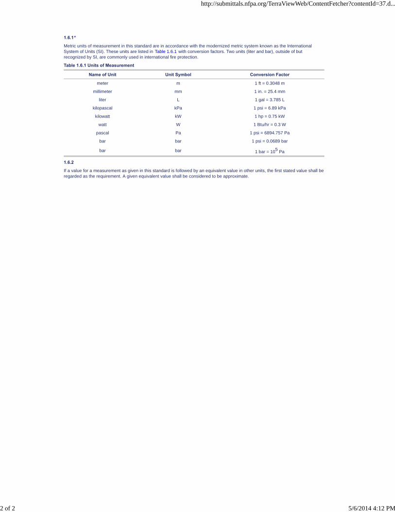
Metric units of measurement in this standard are in accordance with the modernized metric system known as the InternationalSystem of Units (SI). These units are listed in Table 1.6.1 with conversion factors. Two units (liter and bar), outside of butrecognized by SI, are commonly used in international fire protection.
Table 1.6.1 Units of Measurement
Name of Unit Unit Symbol Conversion Factor
meter m 1 ft = 0.3048 m
millimeter mm 1 in. = 25.4 mm
liter L 1 gal = 3.785 L
kilopascal kPa 1 psi = 6.89 kPa
kilowatt kW 1 hp = 0.75 kW
watt W 1 Btu/hr = 0.3 W
pascal Pa 1 psi = 6894.757 Pa
bar bar 1 psi = 0.0689 bar
bar bar 1 bar = 105 Pa
1.6.2
If a value for a measurement as given in this standard is followed by an equivalent value in other units, the first stated value shall beregarded as the requirement. A given equivalent value shall be considered to be approximate.
http://submittals.nfpa.org/TerraViewWeb/ContentFetcher?contentId=37.d...
2 of 2 5/6/2014 4:12 PM

NFPA 37®, Standard for the Installation and Use of Stationary Combustion Engines and Gas Turbines, 2010 Edition
NFPA STANDARDS DEVELOPMENT SITESECOND DRAFT REPORTClosing Date: July 19, 2013 NOTE: All Public Comment must be received by 5:00 pm EST/EDST on the published Closing Date.
Quick Print
PCs [1] SR-1 Hide Legislative
SR-19 Hide Legislative
Chapter 2 Referenced Publications
2.1 General.
The documents or portions thereof listed in this chapter are referenced within this standard and shall be considered part of therequirements of this document.
2.2 NFPA Publications.
National Fire Protection Association, 1 Batterymarch Park, Quincy, MA 02169-7471.
NFPA 10, Standard for Portable Fire Extinguishers, 2013 0 edition.
NFPA 11, Standard for Low-, Medium-, and High-Expansion Foam, 2010 edition.
NFPA 12, Standard on Carbon Dioxide Extinguishing Systems, 2011 08 edition.
NFPA 12A, Standard on Halon 1301 Fire Extinguishing Systems, 2009 edition.
NFPA 13, Standard for the Installation of Sprinkler Systems, 2013 0 edition.
NFPA 15, Standard for Water Spray Fixed Systems for Fire Protection, 2012 07 edition.
NFPA 17, Standard for Dry Chemical Extinguishing Systems, 2013 09 edition.
NFPA 30, Flammable and Combustible Liquids Code, 2012 08 edition.
NFPA 54, National Fuel Gas Code, 2012 09 edition.
NFPA 58, Liquefied Petroleum Gas Code, 2014 08 edition.
NFPA 70®, National Electrical Code®, 2014 08 edition.
NFPA 72®, National Fire Alarm and Signaling Code, 2013 0 edition.
NFPA 211, Standard for Chimneys, Fireplaces, Vents, and Solid Fuel–Burning Appliances, 2013 0 edition.
NFPA 750, Standard on Water Mist Fire Protection Systems, 2014 0 edition.
NFPA 2001, Standard on Clean Agent Fire Extinguishing Systems, 2012 08 edition.
2.3 Other Publications.
2.3.1 API Publications.
American Petroleum Institute, 1220 L Street, NW, Washington, DC 20005-4070.
API 620, Design and Construction of Large Welded Low-pressure Storage Tanks, 11th edition, February 2008.
API 650, Welded Tanks for Oil Storage, 11th edition, June 2007.
2.3.2 ASME Publications.
American Society of Mechanical Engineers, Three Park Avenue, New York, NY 10016-5990.
ANSI/ASME Boiler and Pressure Vessel Code, 2007.
ANSI/ASME B31.3, Process Piping, 2002.
2.3.3 MSS Publications.
Manufacturers Standardization Society of the Valve and Fittings Industry Inc., 127 Park Street NE, Vienna, VA 22180.
MSS SP-69, Pipe Hangers and Supports — Selection and Application, 2003.
2.3.4 UL Publications.
Underwriters Laboratories Inc., 333 Pfingsten Road, Northbrook, IL 60062-2096.
ANSI/UL 900, Standard for Air Filter Units, 2004 , with revisions through November 2012 09 .
2.3.5 Other Publications.
Merriam-Webster’s Collegiate Dictionary, 11th edition, Merriam-Webster, Inc., Springfield, MA, 2003.
2.4 References for Extracts in Mandatory Sections.
NFPA 30, Flammable and Combustible Liquids Code, 2012 08 . edition.
NFPA 85, Boiler and Combustion Systems Hazards Code, 2007 . 2011. edition.
http://submittals.nfpa.org/TerraViewWeb/ContentFetcher?contentId=37.d...
1 of 1 5/6/2014 4:13 PM
NFPA 37®, Standard for the Installation and Use of Stationary Combustion Engines and Gas Turbines, 2010 Edition
NFPA STANDARDS DEVELOPMENT SITESECOND DRAFT REPORTClosing Date: July 19, 2013 NOTE: All Public Comment must be received by 5:00 pm EST/EDST on the published Closing Date.
Quick PrintChapter 3 Definitions
3.1 General.
The definitions contained in this chapter shall apply to the terms used in this standard. Where terms are not defined in this chapteror within another chapter, they shall be defined using their ordinarily accepted meanings within the context in which they are used.Merriam-Webster’s Collegiate Dictionary, 11th edition, shall be the source for the ordinarily accepted meaning.
3.2 NFPA Official Definitions.
3.2.1* Approved.
Acceptable to the authority having jurisdiction.
3.2.2* Authority Having Jurisdiction (AHJ).
An organization, office, or individual responsible for enforcing the requirements of a code or standard, or for approving equipment,materials, an installation, or a procedure.
3.2.3 Labeled.
Equipment or materials to which has been attached a label, symbol, or other identifying mark of an organization that is acceptableto the authority having jurisdiction and concerned with product evaluation, that maintains periodic inspection of production of labeledequipment or materials, and by whose labeling the manufacturer indicates compliance with appropriate standards or performance ina specified manner.
3.2.4* Listed.
Equipment, materials, or services included in a list published by an organization that is acceptable to the authority havingjurisdiction and concerned with evaluation of products or services, that maintains periodic inspection of production of listedequipment or materials or periodic evaluation of services, and whose listing states that either the equipment, material, or servicemeets appropriate designated standards or has been tested and found suitable for a specified purpose.
3.2.5 Shall.
Indicates a mandatory requirement.
3.2.6 Should.
Indicates a recommendation or that which is advised but not required.
3.3 General Definitions.
3.3.1 Class I Fuel.
For the purpose of this standard, any liquid fuel having a flash point below 37.8°C (100°F).
3.3.2* Enclosure.
A cover intended to protect an engine and related equipment.
3.3.3 Engines.
Prime movers such as internal combustion engines, external combustion engines, gas turbine engines, rotary engines, and freepiston engines using either gaseous fuels or liquid fuels or combinations thereof.
3.3.3.1 Combustion Gas Turbine Engines.
An engine that produces shaft power utilizing the Brayton (joule) cycle, where atmospheric air is drawn in and compressed and thecompressed air then flows into a combustion chamber where fuel is injected and continuous combustion occurs, resulting inhigh-pressure hot gas to the expansion section (turbine) where the heat energy is converted to rotating, mechanical energy.
3.3.3.2* Engines for Emergency Use.
Engines that operate under limited-use conditions to support critical operations in the protection of life, property, or both.
3.3.3.3 Portable Engines.
Engines mounted on skids, wheels, or otherwise arranged so that they can be moved from place to place as the required servicedictates.
3.3.3.4* Reciprocating Engines.
An engine that uses a spark plug to ignite a fuel–air mixture (e.g., otto cycle engine) or an engine in which high-pressurecompression raises the air temperature to the ignition temperature of the injected fuel (e.g., diesel cycle engine).
3.3.4 Flue Gas Temperature.
The temperature of the flue products at the point or points of passing close to or through combustible materials or at the entrance toa chimney, whichever is applicable.
3.3.5 Gas Train.
The portion of the fuel gas supply piping starting with and including the equipment isolation valve and extending to the point atwhich the fuel enters the prime mover.
3.3.6 Hazardous Location.
An area where flammable or combustible gases or liquids or combustible dusts or flyings usually exist.
http://submittals.nfpa.org/TerraViewWeb/ContentFetcher?contentId=37.d...
1 of 2 5/6/2014 4:13 PM
3.3.7* Horsepower Rating (Combustion Gas Turbines).
The ANSI standard rated power of an engine at the output shaft at 1.01325 bar (14.7 psia) atmospheric pressure, at 15°C (59°F),and at a relative humidity of 60 percent.
3.3.8* Horsepower Rating (Reciprocating Engines).
The power of an engine measured at the flywheel or output shaft at standard SAE conditions of 752.1 mm Hg (29.61 in. Hg)barometer and at 25°C (77°F) inlet air temperature.
3.3.9 Remote Location.
A location suitably separated from the engine installation so as to be accessible during an engine fire.
3.3.10 Spark Protected.
Electrical equipment enclosed in a tight case or protected by shields, screens, or insulation that contains sparks or prevents theiremission.
3.3.11 Tank.
3.3.11.1 Engine-Mounted Tank.
A fuel tank furnished and mounted on the engine or engine-frame by the engine manufacturer.
3.3.11.2* Fuel Tank.
A tank containing fuel for an engine(s).
3.3.11.3 Secondary Containment Tank.
A tank that has an inner and outer wall with an interstitial space (annulus) between the walls and that has a means for monitoringthe interstitial space for a leak. [30, 2012 08 ]
3.3.12 Valve.
3.3.12.1* Automatic Safety Shutoff Valve (ASSV).
A valve that, upon shutdown conditions, will automatically stop the flow of gas to the engine or turbine. (See 5.4.3 and 5.4.4.)
3.3.12.2 Automatic Safety Vent Valve.
A valve that, upon closing of the automatic safety shutoff valves (ASSVs), automatically vents the volume of gas between the twoASSVs to atmosphere.
3.3.12.3 Carburetion Valve.
A control valve that meets the functional requirements of an automatic safety shutoff valve (ASSV) by being capable ofautomatically stopping the flow of gas to the engine.
3.3.12.4* Equipment Isolation Valve.
The manually operated valve that isolates the balance of the gas train and the prime mover from the gas supply.
3.3.12.5 Vent Valve.
A valve used to allow venting of air or gas from the system to the atmosphere. [85, 2011 07 ]
3.3.13 Zero Governor Regulator.
A gas pressure regulator equipped with a counter spring beneath the valve that requires an external impulse signal such as toploading with pressure or generating vacuum in the downstream piping.
http://submittals.nfpa.org/TerraViewWeb/ContentFetcher?contentId=37.d...
2 of 2 5/6/2014 4:13 PM
NFPA 37®, Standard for the Installation and Use of Stationary Combustion Engines and Gas Turbines, 2010 Edition
NFPA STANDARDS DEVELOPMENT SITESECOND DRAFT REPORTClosing Date: July 19, 2013 NOTE: All Public Comment must be received by 5:00 pm EST/EDST on the published Closing Date.
Quick PrintChapter 4 Engines — General Requirements
4.1 Engine Locations.
4.1.1 General Requirements.
4.1.1.1
Engines shall be situated so that they are readily accessible for maintenance, repair, and fire fighting.
4.1.1.2*
The air supply shall be designed to meet at least the minimum requirements for combustion, cooling, and ventilation and to preventflue gas products from being drawn from stacks or flues of boilers or other combustion devices.
4.1.1.3*
Combustible materials shall not be stored in rooms or enclosures housing engines, other than those combustible materials requiredfor day-to-day operations/maintenance. Such materials shall be stored properly.
4.1.1.4
Engines fueled by a Class I fuel or by liquid-phase LP-Gas shall not be installed in rooms containing fired equipment or openflames.
4.1.1.5
Combustion air filters mounted directly on engines or turbines shall be listed in accordance with ANSI/UL 900, Standard for Air FilterUnits.
4.1.2 Engines Located in Structures.
4.1.2.1* Engine Rooms.
4.1.2.1.1
Engine rooms located within structures shall have interior walls, floors, and ceilings of at least 1-hour fire resistance rating, unlessotherwise permitted by 4.1.2.1.2.
4.1.2.1.2
The ceiling of rooms located on the top floor of a structure shall be permitted to be noncombustible or protected with an automaticfire suppression system.
4.1.2.1.3*
Engine rooms shall have ventilation that is adequate to prevent a hazardous accumulation of flammable vapors or gases, bothwhen the engine is operating and when it is shut down.
4.1.2.1.4
Engine rooms attached to structures shall comply with 4.1.2.2.1 and 4.1.2.2.3 except that the common wall shall have a fireresistance rating of at least 1 hour.
4.1.2.1.5*
Openings from an engine room to other sections of the structure shall be provided with automatic or self-closing fire doors ordampers corresponding to the rating of the walls in which they are located.
4.1.2.1.6
Rooms containing engines utilizing a Class I fuel shall be located on an exterior wall, the construction of which shall provide readyaccessibility for fire-fighting operations through the provision of doors, access openings, windows, louvers, or lightweight,noncombustible wall panels.
4.1.2.2 Dedicated Detached Structures.
4.1.2.2.1*
Dedicated detached structures shall be of noncombustible or fire-resistive construction.
4.1.2.2.2
Dedicated detached structures shall be located at least 1.5 m (5 ft) from openings in walls and at least 1.5 m (5 ft) from structureshaving combustible walls. A minimum separation shall not be required where any of the following conditions exist:
(1) The exposing wall of the detached structure has a fire resistance rating of at least 1 hour.
(2) The exposed wall of the adjacent structure has a fire resistance rating of at least 1 hour.
(3) The detached structure is protected by an automatic fire protection system.
4.1.2.2.3*
Dedicated detached structures shall have ventilation designed to prevent a hazardous accumulation of flammable vapors or gases,both when the engine is operating and when it is shut down.
4.1.3 Engines Located on Roofs.
http://submittals.nfpa.org/TerraViewWeb/ContentFetcher?contentId=37.d...
1 of 3 5/6/2014 4:13 PM

PCs [1]
4.1.3.1
Engines, and their weatherproof housings, if provided, that are installed on roofs of structures shall be located at least 1.5 m (5 ft)from openings in walls and at least 1.5 m (5 ft) from structures having combustible walls. A minimum separation shall not berequired where the following conditions exist:
(1) The adjacent wall of the structure has a fire resistance rating of at least 1 hour.
(2)
4.1.3.2
An oil containment system consisting of a curb or dike having a capacity at least equal to the total capacity of the lubricating oilsystem or the liquid fuel system, whichever is greater, shall be provided. This system shall also comply with applicable requirementsof Chapter 6.
4.1.3.3*
The surface beneath the engine and beyond the engine and the oil containment dike shall be noncombustible to a minimumdistance of 300 mm (12 in.).
4.1.4 Engines Located Outdoors.
Engines, and their weatherproof housings, if provided, that are installed outdoors shall be located at least 1.5 m (5 ft) fromopenings in walls and at least 1.5 m (5 ft) from structures having combustible walls. A minimum separation shall not be requiredwhere either of the following conditions exist:
(1) All walls of the structure that are closer than 1.5 m (5 ft) from the engine enclosure have a fire resistance rating of at least 1hour.
(2)
4.2 Foundations.
Engines shall be supported on foundations or secured to a noncombustible framework.
4.3* Hazardous Locations.
In hazardous locations, engines that neither compress a flammable gas nor pump a flammable liquid shall meet the following threecriteria:
(1) They shall be installed in an enclosure of fire-resistive construction.
(2) They shall be ventilated from a nonhazardous outside area.
(3) They shall have outside access only.
4.4 Engines Handling Hazardous Materials (Other Than Their Own Fuel Supply).
4.4.1
The use of an engine-driven unit to compress a flammable gas or to pump a flammable liquid shall be permitted provided thecombination unit or groups of such combined units are isolated from areas not having a similar hazard.
4.4.2*
Isolation shall be permitted to be achieved by either locating the unit outdoors or employing indoor structural separation inaccordance with 4.1.2, except as modified by all of the following:
(1) Provision shall be made for the venting of an explosion.
(2) Rooms containing combustion engines located within structures shall have interior walls, floors, and ceilings of at least 2-hourfire resistance rating.
(3) The rooms or structures described in 4.4.2(2) shall be ventilated in an approved manner from a nonhazardous area.
4.4.3 Engine Accessories for Hazardous Locations.
4.4.3.1
Each spark-ignition engine comprising part of a unit that compresses a flammable gas or pumps a flammable liquid shall havemagnetos or distributors and coils of the spark-protected type. All leads shall be positively attached.
4.4.3.2
Ventilation openings in such devices shall be protected by a fire screen unless the device is purged, pressurized, or otherwiseprotected in an approved manner.
4.4.3.3
Ignition wires shall be positively attached at each end by use of the outer sheath of the insulation.
4.4.3.4
Spark plugs shall be fully shielded against flashover. Fully radio-shielded spark plugs or spark plugs provided with insulating bootsshall be permitted.
4.4.3.5
Flame-arresting equipment shall be attached to the engine air intake to avoid blowoff or rupture. A mechanically attached air filtershall be permitted to meet this requirement.
4.4.3.6
Starter, generator, and associated electrical equipment attached to engines shall be of the spark-protected type.
* The weatherproof enclosure is constructed of noncombustible materials and it has been demonstrated that a fire within theenclosure will not ignite combustible materials outside the enclosure.
* The weatherproof enclosure is constructed of noncombustible materials and it has been demonstrated that a fire within theenclosure will not ignite combustible materials outside the enclosure.
http://submittals.nfpa.org/TerraViewWeb/ContentFetcher?contentId=37.d...
2 of 3 5/6/2014 4:13 PM
4.4.3.7
Fan belts shall be electrically conductive (nonsparking).
4.5 Electrical Installations.
4.5.1
Electrical installations in rooms containing engines shall comply with NFPA 70, National Electrical Code.
4.5.2
Engine rooms or other locations shall not be classified as hazardous locations as defined in Article 500 of NFPA 70, NationalElectrical Code, solely by reason of the engine fuel, lubricating oil, or hydraulic fluid.
4.5.3 Engine Wiring.
Wire and insulation materials shall have all of the following characteristics:
(1) Capacity to remain flexible over typical engine operating temperature ranges
(2) Capacity to have the minimum possible absorption of oils, fuels, and other fluids commonly found on or near the engine
(3) Rated for continuous use at the maximum range of temperatures that will occur where installed
4.5.3.1
Wiring shall be protected by either fuses or circuit breakers in accordance with its ampacity.
4.5.3.2
The wire shall be stranded annealed copper.
4.5.3.3
The ground circuits on engine wiring shall be permitted to be any of the following:
(1) Green
(2) Green with yellow trace
(3) Braided uninsulated cable
4.5.3.4*
Electrical control circuits on engines not for emergency use shall be designed to shut down the engine automatically in the event ofbreaking, disconnecting, or cutting of the control wire.
4.5.3.5
The requirements of 4.5.3 shall not apply to ignition wiring, thermocouples, or microprocessor wiring.
4.5.4
Batteries, wiring, and electrical devices shall be protected against arcing and accidental shorting.
4.6* General Installation Requirements.
Engines and their appurtenances shall be installed in accordance with the following:
(1) Applicable NFPA codes and standards
(2) Industry standards
(3) User requirements
(4) Manufacturer's installation instructions
(5)* Applicable local building codes with respect to wind and seismic design requirements.
http://submittals.nfpa.org/TerraViewWeb/ContentFetcher?contentId=37.d...
3 of 3 5/6/2014 4:13 PM
NFPA 37®, Standard for the Installation and Use of Stationary Combustion Engines and Gas Turbines, 2010 Edition
NFPA STANDARDS DEVELOPMENT SITESECOND DRAFT REPORTClosing Date: July 19, 2013 NOTE: All Public Comment must be received by 5:00 pm EST/EDST on the published Closing Date.
Quick Print
SR-20 Hide Legislative
PCs [1] SR-17 Hide Legislative
PCs [1] SR-16 Hide Legislative
Chapter 5 Fuel Supply — Gaseous
5.1* Gas Piping.
5.1.1
Gas piping shall be installed in accordance with the following methods:
(1) All fuel gas systems at service pressures equal to or less than a gauge pressure of 860 kPa (gauge pressure of 125 psig )shall be installed in accordance with NFPA 54, National Fuel Gas Code.
(2) All fuel gas systems at service pressures in excess of a gauge pressure of 860 kPa (gauge pressure of 125 psig ), other thanLP-Gas systems, shall be installed in accordance with ANSI/ASME B31.3, Process Piping.
(3) LP-Gas systems, whether liquid or vapor phase, shall be installed in accordance with the provisions of NFPA 58, LiquefiedPetroleum Gas Code.
5.1.2*
Plastic pipe shall not be used to carry fuel within a room housing an engine(s).
5.1.3
Approved metallic flexible connectors shall be permitted for protection against damage caused by settlement, vibration, expansion,contraction, or corrosion.
5.1.4
Approved nonmetallic connectors shall be permitted for protection against damage caused by settlement, vibration, expansion,contraction, or corrosion except for LP-Gas in the liquid phase.
5.2* Gas Trains.
5.2.1
Gas trains, as defined in 3.3.5, shall contain at least the following safety components:
(1) An equipment isolation valve
(2) A gas pressure regulator, if the prime mover does not operate at the gas supply pressure
(3) Two automatic safety shutoff valves ( ASSVs)
(4) A manual leak test valve for each ASSV or an alternative means of proving the full closure of the ASSV
(5)
(6)
(7) A vent valve or a valve proving system (VPS) for inlet gas pressures greater than a gauge pressure of 14 kPa (gaugepressure of 2 psi)
(8) A flame arrester, where biogases are used and there is risk of having oxygen in the biogas
(9) A gas filter or strainer
(10)
5.2.2
For engines operating at more than a gauge pressure of 14 kPa (gauge pressure of 2 psi) inlet gas pressure to the equipmentisolation valve, one of the following shall be provided:
(1) A vent valve, located between the two automatic safety shutoff valves, that shall fail open without an externally appliedsource of power and that shall discharge outdoors
(2) At least one safety valve shall be fitted with a proof-of-closure switch
(3) A listed valve proving system (VPS) to prove the two automatic safety shutoff valves upon each startup or after eachshutdown
, a vent valve shall be provided between the two ASSVs. This vent valve shall fail open without an externally supplied source ofpower and shall discharge outdoors.
5.3 Regulators.
5.3.1
Except as provided for in 5.3.1.2, a gas pressure regulator shall vent to the atmosphere outside the structure at a point at least 1.5m (5 ft) away from any structure opening.
* A low-pressure limit control for engines with a 732 kW (2.5 million Btu/hr) full-load input or greater
* A high-pressure limit control (manual reset) for engines with a 732 kW (2.5 million Btu/hr) full-load input or greater
* Any other components or equipment that the manufacturer requires for safe operation
http://submittals.nfpa.org/TerraViewWeb/ContentFetcher?contentId=37.d...
1 of 3 5/6/2014 4:13 PM
PCs [1] SR-15 Hide Legislative
PCs [1]
5.3.1.1
Such vents and any connected piping shall be sized to vent the required volume of gas.
5.3.1.2*
The following devices shall not be required to be vented to the outside when installed in accordance with their listing:
(1) Any regulator or zero governor that operates with gas pressure on both sides of the diaphragm
(2) A full lock-up regulator
(3) A listed regulator incorporating with a listed vent-limiting device
(4) A regulator incorporating a vent-limiting system with an orifice sized for 2.5 ft 3 /hr or less, based on natural gas
5.3.2
When the gas pressure on the upstream side of a non-full lock-up regulator is more than a gauge pressure of 3.5 kPa (0.5 psi), arelief valve shall be installed on the downstream side of the regulator. This relief valve shall vent to the outside of the structure at apoint at least 1.5 m (5 ft) away from any structure opening.
5.3.2.1
Such relief valves and any connected piping shall be sized to vent the required volume of gas.
5.4 Valves.
5.4.1* Manual Shutoff Valves.
5.4.1.1
Multiple manual shutoff valves shall be permitted in the gas train to allow additional isolation for maintenance reasons.
5.4.1.2
If the shutoff valve is locked open, the key shall be secured in a well-marked, accessible location near the valve.
5.4.1.3*
A manual shutoff valve in a remote location shall be provided to isolate the fuel supply.
5.4.2* Equipment Isolation Valves.
In multiple-engine installations, the equipment isolation valve shall be located no further from the engine than the first takeoff orbranch pipe that serves only that engine.
5.4.3* Automatic Safety Shutoff Valves (ASSVs) for Engines Other Than Gas Turbines.
The ASSVs shall stop the flow of fuel within 1 second in the event the engine stops from any cause. The ASSV shall fail closedwithout an externally applied source of power.
5.4.3.1*
It shall be permissible to replace one of the ASSVs required by Section 5.2 with one of the following devices, provided the devicewill automatically shut off the flow of fuel within 1 second if the engine stops from any cause:
(1) Carburetion valve
(2) Zero governor–type regulating valve
(3) Auxiliary valve
5.4.3.2*
Where a carburetion valve or zero governor–type regulating valve is used as one of the required ASSVs, the downstream manualleak test valve shall not be required.
5.4.4 Automatic Safety Shutoff Valves (ASSVs) for Gas Turbines.
The two ASSVs required by Section 5.2 shall operate as follows:
(1) One of the ASSVs shall stop the flow of fuel when the engine is shut down under normal conditions.
(2) Both ASSVs shall stop the flow of fuel if the engine must be shut down due to abnormal or emergency operating conditions asspecified by the manufacturer.
5.4.4.1
The ASSV shall stop flow of fuel to the engine as follows:
(1) For combustion turbines supplied by piping 150 mm (6 in.) diameter or less, within 3 seconds
(2) For combustion turbines supplied by piping greater than 150 mm (6 in.) diameter, within 5 seconds
5.4.4.2
The ASSV shall fail closed without an externally supplied source of power.
5.4.4.3*
It shall be permissible to replace one of the ASSVs with a control valve, provided the device will automatically shut off the flow offuel within the time limits specified in 5.4.4.1(1) and 5.4.4.1(2), whichever is applicable.
http://submittals.nfpa.org/TerraViewWeb/ContentFetcher?contentId=37.d...
2 of 3 5/6/2014 4:13 PM
5.4.4.4*
If the engine is shut down for abnormal or emergency operating conditions as specified by the manufacturer, a vent valve shall openautomatically to depressurize the included piping. The vent shall fail open without an externally supplied source of power and shalldischarge outdoors.
5.4.4.5*
One ASSV shall be located external to the combustion turbine package and any associated building.
5.5 Pressure-Boosting Equipment.
5.5.1
Boosters or compressors, if used, shall be approved for the service intended.
5.5.2
Receivers, if used, shall be certified with a stamp that they have been designed, constructed, and tested as required by Section VIII,Division 1, “Pressure Vessels,” of the ANSI/ASME Boiler and Pressure Vessel Code.
http://submittals.nfpa.org/TerraViewWeb/ContentFetcher?contentId=37.d...
3 of 3 5/6/2014 4:13 PM
NFPA 37®, Standard for the Installation and Use of Stationary Combustion Engines and Gas Turbines, 2010 Edition
NFPA STANDARDS DEVELOPMENT SITESECOND DRAFT REPORTClosing Date: July 19, 2013 NOTE: All Public Comment must be received by 5:00 pm EST/EDST on the published Closing Date.
Quick PrintChapter 6 Fuel Supply — Liquid
6.1* Design and Construction of Liquid Fuel Tanks.
Fuel tanks shall meet one of the following criteria:
(1) Constructed in accordance with the applicable requirements of NFPA 30, Flammable and Combustible Liquids Code
(2) Listed as “Steel-Inside Tanks for Oil Burner Fuel”
(3) Listed as “Underground Tanks for Flammable Liquids”
(4) Listed as “Aboveground Tanks for Flammable Liquids”
(5) Constructed in accordance with API 650, Welded Tanks for Oil Storage
(6) Constructed in accordance with API 620, Design and Construction of Large Welded Low-pressure Storage Tanks
Exception: Fuel tanks mounted on the engine by the manufacturer for gravity feed to a carburetor.
6.1.1
Metallic tanks shall be liquidtight with welded or brazed joints.
6.1.2
Nonmetallic tanks shall be of liquidtight, one-piece construction.
6.2* Installation Criteria for Fuel Tanks Containing Class I Fuels.
6.2.1
Tanks for Class I fuels shall be located underground or aboveground outside of structures.
6.2.2*
Fuel tanks shall be installed in accordance with NFPA 30, Flammable and Combustible Liquids Code.
6.3* Installation Criteria for Fuel Tanks Containing Liquid Fuels Other Than Class I Fuels.
6.3.1 General.
Engine-mounted tanks shall be securely mounted on the engine assembly and protected against all of the following:
(1) Vibration
(2) Physical damage
(3) Engine heat
(4) Exhaust piping heat
6.3.2 Fuel Tanks Inside Structures.
6.3.2.1
Fuel tanks inside structures shall be securely mounted on noncombustible supports.
6.3.2.2*
Fuel tanks not in a room by themselves shall not exceed 2500 L (660 gal) capacity. Fuel tanks larger than 2500 L (660 gal) capacityshall be enclosed in a room in accordance with 6.3.5 or 6.3.6. Not more than one 2500 L (660 gal) capacity tank, or two or moretanks with an aggregate capacity of not more than 2500 L (660 gal), shall be connected to any one engine.
Exception: Fuel tanks of any size shall be permitted within engine rooms or mechanical spaces, provided the engine or mechanicalroom is designed using recognized engineering practices with suitable fire detection, fire suppression, and containment means toprevent the spread of fire beyond the room of origin.
6.3.2.3*
The aggregate capacity of all fuel tanks in a structure shall not exceed 5000 L (1320 gal) unless that portion exceeding 5000 L(1320 gal) is enclosed in a room in accordance with 6.3.5 or 6.3.6.
Exception: Fuel tanks of any size shall be permitted within engine rooms or mechanical spaces, provided the engine or mechanicalroom is designed using recognized engineering practices with suitable fire detection, fire suppression, and containment means toprevent the spread of fire beyond the room of origin.
6.3.2.4
Fuel tanks within structures shall be provided with spill containment consisting of either a wall, a curb, or a dike having a capacity atleast equal to that of the largest tank enclosed.
Exception: A spill containment system of lesser capacity equipped with an overflow or drainage system that is adequate in size andlocation to convey any spillage of fuel to a tank (inside or outside) or to a safe area outside the structure.
6.3.3 Fuel Tanks Outdoors (Aboveground or Underground) or Beneath a Structure.
Fuel tanks located outside, either aboveground or underground, or located beneath a structure shall comply with the applicableprovisions of NFPA 30, Flammable and Combustible Liquids Code.
6.3.4 Fuel Tanks on Roofs.
http://submittals.nfpa.org/TerraViewWeb/ContentFetcher?contentId=37.d...
1 of 4 5/6/2014 4:13 PM
6.3.4.1
Fuel tanks on roofs shall be mounted securely on noncombustible supports.
6.3.4.2
Fuel tanks located on roofs shall be provided with spill containment consisting of a wall, a curb, or a dike having a capacity at leastequal to that of the largest tank enclosed.
Exception No. 1: A spill containment system of lesser capacity equipped with an overflow or drainage system that is adequate insize and location to convey any spillage of fuel to a tank (inside or outside) or to a safe area outside the structure.
Exception No. 2: Listed or approved secondary containment tanks shall be considered as meeting this requirement.
6.3.5* Rooms Housing Only Fuel Tanks with an Aggregate Capacity of 5000 L (1320 gal) or Less.
6.3.5.1
Rooms containing only fuel tanks with an aggregate capacity of 5000 L (1320 gal) or less shall be constructed of walls, floor, andceiling having a fire resistance rating of not less than 1 hour with the walls bonded to the floor.
6.3.5.1.1
If the walls of such rooms extend to and are bonded to the underside of a concrete floor or roof above that has a fire resistancerating of not less than 1 hour, a separate ceiling shall not be required for the room.
6.3.5.1.2
At least 380 mm (15 in.) clearance shall be left around each tank for the purpose of inspection and repair.
6.3.5.2
Each tank room shall be provided with an opening that is protected by a self-closing 1-hour-rated fire door if it opens inside abuilding.
6.3.5.2.1
If an exterior door is provided, it shall be listed for fire exposures.
6.3.5.3
Each tank room shall be provided with spill containment consisting of either a wall, a curb, or a dike having a capacity at least equalto that of the largest tank.
Exception: A spill containment system of lesser capacity equipped with an overflow or drainage system that is adequate in size andlocation to convey any spillage of fuel to a tank (inside or outside) or to a safe area outside the structure.
6.3.5.4* Ventilation.
6.3.5.4.1
Ventilation for tank rooms shall be sufficient to maintain the concentration of vapors within the room at or below 25 percent of thelower flammable limit (LFL) of the fuel used.
6.3.5.4.2
Ventilation shall be accomplished by mechanical or natural means and shall discharge to a safe location outside the building,without recirculation of the exhaust air.
6.3.5.4.3
Provision shall be made for introduction of make-up air in such a manner as to avoid short-circuiting the ventilation and shall bearranged to include all floor areas or pits where flammable vapors can collect.
6.3.6* Rooms Housing Only Fuel Tanks with an Aggregate Capacity of More Than 5000 L (1320 gal).
6.3.6.1
Rooms containing only fuel tanks shall be constructed of walls, floor, and ceiling having a fire resistance rating of not less than 3hours with the walls bonded to the floor.
6.3.6.1.1
If the walls of such rooms extend to and are bonded to the underside of a concrete floor or roof above that has a fire resistancerating of not less than 3 hours, a separate ceiling shall not be required for the room.
6.3.6.1.2
At least 380 mm (15 in.) clearance shall be left around each tank for the purpose of inspection and repair.
6.3.6.2
Any opening of a tank room shall be protected by a self-closing 3-hour fire-rated door or damper assembly as applicable.
6.3.6.3
Each tank room shall be provided with spill containment consisting of either a wall, a curb, or a dike having a capacity at least equalto that of the largest tank.
Exception: A spill containment system of lesser capacity equipped with an overflow or drainage system that is adequate in size andlocation to convey any spillage of fuel to a tank (inside or outside) or to a safe area outside the structure.
6.3.6.4
Floor openings shall be protected by a ramp or curb of sufficient height to contain the entire contents of the tank within the walls tothe height corresponding to the level of fuel that will be retained.
6.3.6.4.1
The curb shall be built to withstand the lateral pressure due to the liquid head, and the walls and floor shall be liquidtight.
Exception: Rooms provided with a spill containment system that is adequate in size and location to convey any spillage of a fuel toa tank (inside or outside) or to a safe area outside the room.
http://submittals.nfpa.org/TerraViewWeb/ContentFetcher?contentId=37.d...
2 of 4 5/6/2014 4:13 PM
6.3.6.5* Ventilation.
6.3.6.5.1
Ventilation for tank rooms shall be sufficient to maintain the concentration of vapors within the room at or below 25 percent of theLFL of the fuel used.
6.3.6.5.2
Ventilation shall be accomplished by mechanical or natural means and shall discharge to a safe location outside the building,without recirculation of the exhaust air.
6.3.6.5.3
Provision shall be made for introduction of make-up air in such a manner as to avoid short-circuiting the ventilation. Thatintroduction of make-up air shall be arranged to include all floor areas or pits where flammable vapors can collect.
6.4 Installation Criteria for Fuel Tanks Containing Liquefied Petroleum Gases.
LP-Gas systems in the liquid phase shall be installed in accordance with the provisions of NFPA 58, Liquefied Petroleum Gas Code.
6.5 Fuel Flow Control.
6.5.1
Liquid fuel supply systems, including drains from carburetors, shall be designed and installed to minimize, as far as practicable, theaccidental discharge of fuel into the engine room or structure.
6.5.2
Alarms, float-controlled valves, or mechanical or remote-reading level gauges or protected sight glass gauges shall be installed toaid personnel in properly operating the fuel system.
6.5.3
Stationary-powered fuel pumps supplying fuel tanks shall have “stop” controls sensitive to a tank's high liquid level.
6.5.4
Fuel tanks supplied by pumps shall be provided with all of the following:
(1) An overflow line
(2) A high-level alarm
(3) A high-level automatic shutoff
6.5.4.1
The overflow line shall be continuous piping, without valves or traps, back to the source tank or to a collection system.
6.5.4.2
The capacity of the overflow line shall exceed the delivery capacity of the supply lines to the fuel tank.
6.5.5
Overflows, vents, fuel piping, and fuel tanks shall not be located at or near engine air intake, exhaust piping, mufflers, or filters.
6.5.6
Pressure relief valves and relief piping shall be provided where the potential exists to overpressurize the fuel system piping.
6.5.6.1
Relief piping shall be routed, without valves or traps, back to the source tank or to a collection system.
6.5.7* Fuels That Require Heating.
6.5.7.1
Fuel shall be constantly recirculated from the fuel tanks through heaters regardless of engine fuel demand.
6.5.7.2
Fuel-heating systems shall include thermostatic controls and suitable pressure and temperature gauges.
6.6 Filling.
6.6.1
Engine-mounted tanks for Class I fuels shall be filled by a closed piping system.
6.6.1.1
Filling by approved safety cans shall be permitted when the engine is shut down and engine surface temperature is below theautoignition temperature of the fuel.
6.6.2
Engine-mounted tanks for liquid fuels other than Class I fuels shall be filled by a closed piping system.
6.6.2.1
Filling from a container shall be permitted when the engine is shut down and engine surface temperature is below the autoignitiontemperature of the fuel.
6.6.3
Piping for fuel tanks other than engine-mounted tanks shall be in accordance with Chapter 27 of NFPA 30, Flammable andCombustible Liquids Code.
http://submittals.nfpa.org/TerraViewWeb/ContentFetcher?contentId=37.d...
3 of 4 5/6/2014 4:13 PM
6.6.3.1
The fill pipe shall terminate outside the building at a point at least 600 mm (24 in.) from any building opening at the same or lowerlevel.
6.7 Vent Piping.
6.7.1
Vent piping shall be installed in accordance with Chapter 27 of NFPA 30, Flammable and Combustible Liquids Code.
6.7.1.1
The vent pipe shall terminate outside the building at a point at least 600 mm (24 in.) from any building opening at the same or lowerlevel.
6.8 Fuel Piping, Valves, and Fittings.
6.8.1*
Piping shall be in accordance with Chapter 27 of NFPA 30, Flammable and Combustible Liquids Code, except that piping shall besteel or other metal and the provisions of 6.8.2 shall apply.
6.8.2
Piping systems shall be supported and protected against physical damage and excessive stresses in accordance with MSS SP-69,Pipe Hangers and Supports — Selection and Application.
6.8.2.1*
Approved metallic or nonmetallic flexible connectors shall be permitted to protect the piping system against damage caused bysettlement, vibration, expansion, contraction, or corrosion.
6.8.3*
Valves shall be provided to control the flow of liquid fuel in normal operation and to shut off the flow of fuel in the event of a pipebreak.
6.8.3.1
The liquid fuel supply for a gas turbine shall include two stop valves or equivalent valves in series, with proof of closure, in the fuelline to each combustion turbine.
6.8.3.1.1
These valves shall operate automatically to stop the flow of fuel in the event the engine stops for any reason.
6.8.3.1.2
Means shall be provided to prevent or relieve excess pressure between these valves.
6.8.4
Piping to aboveground supply tanks filled from tank cars or tank vehicles by centrifugal pumps shall be provided with check valvesto prevent backflow.
6.9 Transfer of Liquid Fuel to Engines.
Liquid fuel shall feed to engines by pumps.
6.9.1
Fuel tanks mounted on the engine by the engine manufacturer for fuel feed to a carburetor shall be permitted.
http://submittals.nfpa.org/TerraViewWeb/ContentFetcher?contentId=37.d...
4 of 4 5/6/2014 4:13 PM

NFPA 37®, Standard for the Installation and Use of Stationary Combustion Engines and Gas Turbines, 2010 Edition
NFPA STANDARDS DEVELOPMENT SITESECOND DRAFT REPORTClosing Date: July 19, 2013 NOTE: All Public Comment must be received by 5:00 pm EST/EDST on the published Closing Date.
Quick PrintChapter 7 Lubricating Systems
7.1 General Requirements.
7.1.1
Lubricating oil reservoirs shall include the following protective devices:
(1) A flame arrester on the vent pipe, if the vent terminates in the exhaust gas path
(2) A high-oil-level alarm if the reservoir is filled automatically
(3) A remote shutdown switch for auxiliary lubricating oil pumps, if provided
7.1.2
The vent pipe specified in 7.1.1(1) shall not terminate in a location where the vapors can be drawn into the engine combustion airsupply.
7.2 Combustion Gas Turbines.
7.2.1
Lubricating oil reservoirs provided with heaters shall be provided with a low-oil-level heater shutdown switch set to shut off theheater before the oil level falls to a level below the top of the heater element.
7.2.2
Lubricating oil reservoirs provided with a positive displacement lubricating oil pump shall be provided with a pressure relief valve.
7.2.3
Lubricating oil reservoir vent piping for combustion gas turbines driving compressors that handle flammable gases and utilize acombined lubricating oil and seal oil system shall not terminate in the exhaust gas path.
7.2.4
Lubricating oil reservoirs for combustion gas turbines driving compressors that handle flammable gases and utilize a combinedlubricating oil and seal oil system shall be provided with a connection for an inert gas blanket.
7.3* Lubricating Oil Piping.
Lubricating oil piping shall be in accordance with the provisions of 6.8.1, 6.8.2, and 6.8.3.
7.4 Reciprocating Engines.
7.4.1
On engines where crankcase explosions can be a hazard, explosion venting shall be provided or means shall be used to maintain anonflammable atmosphere in the crankcase.
7.4.2
Auxiliary reservoir oil supply chambers, if used, shall be vented through either separate vents or a common venting system.
7.4.3
Engines designed to operate with a negative pressure in the crankcase and equipped with a separate lubricating oil sump shall beprovided with check valves in the venting system from the sump.
7.5 Safeguards for Gauging Devices.
Sight gauges or feeds for lubricating oil shall be protected against physical damage to prevent the escape of oil.
http://submittals.nfpa.org/TerraViewWeb/ContentFetcher?contentId=37.d...
1 of 1 5/6/2014 4:14 PM
NFPA 37®, Standard for the Installation and Use of Stationary Combustion Engines and Gas Turbines, 2010 Edition
NFPA STANDARDS DEVELOPMENT SITESECOND DRAFT REPORTClosing Date: July 19, 2013 NOTE: All Public Comment must be received by 5:00 pm EST/EDST on the published Closing Date.
Quick PrintChapter 8 Engine Exhaust Systems
8.1 Design and Construction.
8.1.1*
Engine exhaust systems shall be designed and constructed such that the system can withstand the anticipated exhaust gastemperatures.
8.1.2*
Exhaust systems shall be designed and constructed to withstand the intended service.
8.1.3
Chimneys, where required, shall be constructed and installed in accordance with NFPA 211, Standard for Chimneys, Fireplaces,Vents, and Solid Fuel–Burning Appliances.
8.1.4*
Exhaust systems shall be designed and constructed to withstand forces caused by the ignition of unburned fuel or shall haveprovisions to relieve those forces without damaging the exhaust system.
8.1.5*
Low points in exhaust systems shall have drains.
8.2 Installation.
8.2.1
Exhaust systems shall be connected to the engine to prevent the escape of sparks, flame, or flue gas within the structure.
8.2.2
Engine exhaust systems shall have one or more flexible connectors if necessary to minimize the risk of a leak in the engine exhaustsystem because of engine vibration or thermal expansion.
8.2.3 Exhaust System Termination.
8.2.3.1*
Exhaust systems shall terminate outside the structure at a point where hot gases, sparks, or products of combustion will dischargeto a safe location.
8.2.3.2
Exhaust system terminations shall not be directed toward combustible material or structures or into atmospheres containingflammable gases, flammable vapors, or combustible dusts.
8.2.3.3
Exhaust systems equipped with spark-arresting mufflers shall be permitted to terminate in Division 2 locations or Zone 2 locations,as defined in Article 500 and Article 505 of NFPA 70®, National Electrical Code®.
8.2.4
Where necessary to prevent personnel burns, exhaust systems shall be guarded.
8.2.5
Exhaust systems shall consist of metal, masonry, or factory-built chimneys where they pass through a floor, ceiling, attic, orconcealed space.
8.2.5.1*
If an engine exhaust system connects to the same flue as other fuel-burning appliances, the engine exhaust shall enter the flue adistance of at least 11⁄2 times the equivalent diameter of the exhaust pipe or duct above or below the level of the other appliancevent(s).
8.2.5.1.1
Common venting shall be permitted where appropriate calculations demonstrate that the exhaust from the engine does not reducethe performance of the other appliance(s).
8.2.5.2*
An engine exhaust system that will discharge at positive pressure (greater than atmospheric pressure) shall not enter the same flueas an appliance that relies on natural draft to vent.
8.2.5.2.1
Common venting shall be permitted where appropriate calculations demonstrate that the exhaust from the engine does not reducethe performance of the other appliance(s).
8.3 Clearance from Exhaust Systems with Exhaust Gas Temperatures of Less Than 760°C (1400°F).
http://submittals.nfpa.org/TerraViewWeb/ContentFetcher?contentId=37.d...
1 of 2 5/6/2014 4:14 PM

8.3.1
Exhaust pipes and ducts shall have clearances of at least 225 mm (9 in.) to adjacent combustible materials, except as specified in8.3.2 and 8.3.3. The clearance shall be measured from the outside surface of the exhaust pipe or duct and not from any insulationthat might be present.
8.3.2
Exhaust pipes and ducts passing directly through combustible roofs shall be guarded at the point of passage by ventilated metalthimbles that extend not less than 225 mm (9 in.) on each side (above and below) of roof construction and are at least 150 mm (6in.) in diameter larger than the exhaust pipe or duct.
8.3.3
Exhaust pipes and ducts passing directly through combustible walls or partitions shall be guarded at the point of passage by one ofthe following methods:
(1) Metal ventilated thimbles not less than 300 mm (12 in.) larger in diameter than the exhaust pipe or duct
(2) Metal or burned fire clay thimbles constructed of brickwork or other approved fireproofing materials providing not less than 200mm (8 in.) of insulation between the thimble and combustible material
8.4* Clearance from Exhaust Systems with Exhaust Gas Temperatures of 760°C (1400°F) or Greater.
Exhaust systems with exhaust gas temperatures of 760°C (1400°F) or greater shall comply with NFPA 211, Standard for Chimneys,Fireplaces, Vents, and Solid Fuel–Burning Appliances.
http://submittals.nfpa.org/TerraViewWeb/ContentFetcher?contentId=37.d...
2 of 2 5/6/2014 4:14 PM
NFPA 37®, Standard for the Installation and Use of Stationary Combustion Engines and Gas Turbines, 2010 Edition
NFPA STANDARDS DEVELOPMENT SITESECOND DRAFT REPORTClosing Date: July 19, 2013 NOTE: All Public Comment must be received by 5:00 pm EST/EDST on the published Closing Date.
Quick Print
SR-13 Hide Legislative
Chapter 9 Control and Instrumentation
9.1 All Engines.
Each engine shall be equipped with an automatic engine speed control.
9.2 Reciprocating Engines.
9.2.1* Reciprocating Engines — 7.5 kW (10 hp) or More.
Engines of 7.5 kW (10 hp) or more shall be equipped with protective devices or with equivalent provisions to shut down the enginewhen any of the following conditions occur:
(1) Engine overspeed
(2) High jacket water temperature or high cylinder temperature
(3) Low lubricating oil pressure or, in the case of a splash-lubricated engine, low oil level
(4) High lubricating oil temperature
9.2.1.1
Each engine shall also have provision for shutting down the engine at the engine and from a remote location.
9.2.1.2
Engines that have lubricating oil pumps that are not directly driven by the engine shall also have provision for shutting down thelubricating pump from a remote location.
9.2.1.3
For engines intended for emergency use or that are constantly attended, the protective devices for conditions specified in 9.2.1(2),9.2.1(3), and 9.2.1(4) shall be permitted to be configured as alarms where written procedures exist and operators are trained inestablished actions to take if any of the stated events occur.
9.2.2* Diesel Engines.
Diesel engines installed in hazardous locations shall also have provisions for shutting down the engine by shutting off both the fuelsupply and the combustion air supply.
9.3 Combustion Gas Turbines.
9.3.1*
Combustion gas turbine engines shall be equipped with protective devices or with equivalent provisions to shut down the enginewhen any of the following conditions occur:
(1) Overspeed. Each engine shall have a primary overspeed shutdown control and a backup means for overspeed shutdownindependent of the primary overspeed shutdown.
(2) Low lubricating oil pressure.
(3) High lubricating oil temperature.
(4) Excessive vibration.
(5) Flame failure.
(6) High exhaust temperature.
9.3.1.1
For combustion gas turbine engines that are intended for emergency use or that are constantly attended, the protective devices forconditions specified in 9.3.1(1), 9.3.1(2), and 9.3.1(5) shall be permitted to be configured as alarms where written procedures existand operators are trained in established actions to take if any of the stated events occur.
Global SR-13 Hide Deleted
9.3.2*
Combustion gas turbine engines shall also have the following controls:
(1) Main speed control
(2) Provisions for shutting down the engine from a remote location
(3) Provisions for shutting down, from a remote location, lubricating oil pumps not directly driven by the engine
(4) Means to automatically shut off the fuel supply in the event of a flameout engine shutdown
9.3.3
The combustion gas turbine starting sequence shall include a purge cycle that will result in a nonignitible atmosphere in the turbineand its exhaust system prior to the start of the ignition sequence and the introduction of fuel.
http://submittals.nfpa.org/TerraViewWeb/ContentFetcher?contentId=37.d...
1 of 1 5/6/2014 4:14 PM
NFPA 37®, Standard for the Installation and Use of Stationary Combustion Engines and Gas Turbines, 2010 Edition
NFPA STANDARDS DEVELOPMENT SITESECOND DRAFT REPORTClosing Date: July 19, 2013 NOTE: All Public Comment must be received by 5:00 pm EST/EDST on the published Closing Date.
Quick PrintChapter 10 Instructions
10.1 Operating Instructions.
10.1.1
At least one set of engine operating and maintenance instructions shall be supplied with each installation and shall contain thefollowing:
(1) A detailed explanation of the operation of the engine
(2) Instructions for routine maintenance
(3) Detailed instructions for repair of the engine
(4) Pictorial parts list and parts numbers
(5) Pictorial and schematic electrical drawings of wiring systems, including all of the following:
(a) Operating and safety devices
(b) Control panels
(c) Instrumentation
(d) Annunciators
(6) Instructions on the operation of the fire safety features of the engine
10.1.2
Operating and maintenance procedures shall be developed and implemented for the engines and its auxiliaries based on themanufacturer's instructions and on generally accepted engineering principles and procedures.
10.1.3
One set of operating and maintenance procedures shall be located where they are readily accessible to personnel operating ormaintaining the engine.
10.2* Emergency Instructions.
10.2.1*
Emergency shutdown procedures shall be developed and provided for the engine.
10.2.2
A diagram shall be posted conspicuously near the engine, indicating the location of the fuel shutoff valve(s). Diagrams shall not berequired for installations with clearly identified fuel shutoff valves.
10.2.3
Emergency operating procedures shall be located where they are readily accessible to personnel operating or maintaining theengine.
10.3* Training.
Individuals responsible for the operation and maintenance of the engine shall be trained in operating and maintenance procedures,including emergency shutdown procedures. (See Chapter 11 for fire protection features.)
http://submittals.nfpa.org/TerraViewWeb/ContentFetcher?contentId=37.d...
1 of 1 5/6/2014 4:14 PM
NFPA 37®, Standard for the Installation and Use of Stationary Combustion Engines and Gas Turbines, 2010 Edition
NFPA STANDARDS DEVELOPMENT SITESECOND DRAFT REPORTClosing Date: July 19, 2013 NOTE: All Public Comment must be received by 5:00 pm EST/EDST on the published Closing Date.
Quick PrintChapter 11 Fire Protection Features
11.1* General.
A fire risk evaluation shall be performed for each engine installation, including engine auxiliary equipment, with respect to thefollowing:
(1) Design
(2) Layout
(3) Operating requirements
11.2 Portable Fire Extinguishers.
11.2.1*
Portable fire extinguishers, where provided, shall comply with NFPA 10, Standard for Portable Fire Extinguishers.
11.3 Fire Detection and Alarm Systems.
11.3.1*
Automatic fire detection and alarm systems, where provided, shall comply with NFPA 72, National Fire Alarm and Signaling Code.
11.3.2
The electrical installation and required rating of system components shall comply with NFPA 70, National Electrical Code.
11.3.3
Automatic fuel stop valves, where required by other sections of this standard, shall be arranged to close upon activation of the firedetection system within the fire alarm zone that covers the engine installation, including auxiliary equipment.
11.3.3.1
Where written procedures are in place to direct operator actions upon activation of the detection system, automatic fuel stop valvesfor engines that are used for emergency use or for engines that are constantly attended shall be permitted to remain open.
11.3.4
Mechanical ventilation systems, where provided, shall be arranged to shut down upon activation of the fire detection system withinthe engine enclosure.
11.3.4.1
Where procedures are in place to direct operator actions, mechanical ventilation systems for engines that are used for emergencyuse or for engines that are constantly attended shall be permitted to remain in operation.
11.4 Fire Suppression Systems and Equipment.
11.4.1 Fixed Fire Suppression Systems.
11.4.1.1*
Fixed fire suppression systems, where provided, shall comply with the following standards, as appropriate, unless specifically notedotherwise in this standard:
(1) NFPA 11, Standard for Low-, Medium-, and High-Expansion Foam
(2) NFPA 12, Standard on Carbon Dioxide Extinguishing Systems
(3) NFPA 12A, Standard on Halon 1301 Fire Extinguishing Systems
(4) NFPA 13, Standard for the Installation of Sprinkler Systems
(5) NFPA 15, Standard for Water Spray Fixed Systems for Fire Protection
(6) NFPA 17, Standard for Dry Chemical Extinguishing Systems
(7) NFPA 750, Standard on Water Mist Fire Protection Systems
(8) NFPA 2001, Standard on Clean Agent Fire Extinguishing Systems
11.4.1.2
Fixed fire suppression systems shall be designed to protect all areas where fuel or oil might spray, flow, or collect.
11.4.2 General.
11.4.2.1*
Automatic fuel stop valves, where required by other sections of this standard, shall be arranged to close upon activation of the firesuppression system that covers the engine installation, including auxiliary equipment.
11.4.2.1.1*
Where procedures are in place to direct operator actions upon activation of the fire suppression system that covers the engineinstallation, automatic fuel stop valves for engines that are for emergency use or for engines that are constantly attended shall bepermitted to remain open.
http://submittals.nfpa.org/TerraViewWeb/ContentFetcher?contentId=37.d...
1 of 2 5/6/2014 4:14 PM
SR-8 Hide Legislative
SR-9 Hide Legislative
SR-10 Hide Legislative
11.4.2.2
Mechanical ventilation systems, where provided, shall be arranged to shut down upon activation of the fire suppression systemwithin the engine enclosure.
11.4.2.3*
Where procedures are in place to direct operator actions upon activation of the fire suppression system within the engineinstallation, mechanical ventilation systems for engines that are for emergency use or engines that are constantly attended shall bepermitted to remain in operation.
11.4.2.4
The positioning of the fire suppression systems and equipment shall be such that maintenance access to the engine is maintained.
11.4.3* Foam Fire Suppression Systems.
Foam fire suppression systems shall be designed to provide a foam blanket or foam submergence until it can be demonstrated thatthe engine has cooled to below the autoignition temperature of combustible material present.
11.4.4* Gaseous Agent Fire Systems.
11.4.4.1*
Total flooding gaseous agent systems shall be designed to take into consideration both of the following factors:
(1) The agent concentrations required for the specific combustible materials involved
(2) The specific configuration of the equipment and enclosure
11.4.4.1.1*
Total flooding gaseous suppression systems shall be designed to maintain the design concentration within the enclosure for aminimum of 20 minutes or until it can be demonstrated that the engine has time sufficient to ensure that the fire is extinguished andthat surface temperatures of the engine or turbine have cooled to below the autoignition temperature of combustible materialpresent. , whichever is greater. In lieu of manufacturer or laboratory fire test data demonstrating the actual time to achieveextinguishment and cool-down, the concentration shall be maintained for a minimum of 20 minutes.
11.4.4.2*
Local application gaseous agent suppression systems shall be designed to operate for a minimum of 20 minutes or until it can bedemonstrated that the engine has time sufficient to ensure that the fire is extinguished and that surface temperatures of the engineor turbine have cooled to below the autoignition temperature of combustible material present t, whichever is greater . In lieu ofmanufacturer or laboratory fire test data demonstrating the actual time to achieve extinguishment and cool-down, the dischargeduration shall be maintained for a minuum of 20 minutes.
11.4.5 Automatic Sprinkler and Water Spray Systems.
11.4.5.1*
Automatic sprinkler systems shall be designed to provide a density of 12.2 mm/min (0.3 gpm/ft2) over the most remote 230 m2
(2500 ft2).
11.4.5.1.1
Sprinklers and spray nozzles shall be spaced at a 9 m2 (100 ft2) maximum area of coverage per sprinkler or spray nozzle.
11.4.5.1.2
Sprinkler and water spray system coverage shall be provided to all areas within the enclosure located within 6 m (20 ft) of thefollowing:
(1) The engine
(2) The lubricating oil system
(3) The fuel system
11.4.5.2
Sprinklers and water spray nozzles shall not be directed at engine components that are susceptible to thermal shock ordeformation.
11.4.6 Dry Chemical Fire Suppression Systems.
Dry chemical fire suppression systems shall be designed to operate for a minimum of 20 minutes or until it can be demonstratedthat the engine has cooled to below the autoignition temperature of combustible material present.
11.4.7* Water Mist Suppression Systems.
Water mist suppression systems shall be designed and installed in accordance with their listing for the specific hazards andprotection objectives specified in the listing.
11.4.8 Retrofit of Fire Suppression Systems.
Where retrofit of a fire suppression system is undertaken, the minimum discharge duration shall be 20 minutes, unlessmanufacturer or laboratory fire test data demonstrate that a different discharge duration ensures extinguishment and cool-down tobelow the autoignition temperature of combustible materials present.
http://submittals.nfpa.org/TerraViewWeb/ContentFetcher?contentId=37.d...
2 of 2 5/6/2014 4:14 PM
NFPA 37®, Standard for the Installation and Use of Stationary Combustion Engines and Gas Turbines, 2010 Edition
NFPA STANDARDS DEVELOPMENT SITESECOND DRAFT REPORTClosing Date: July 19, 2013 NOTE: All Public Comment must be received by 5:00 pm EST/EDST on the published Closing Date.
Quick PrintAnnex A Explanatory Material
Annex A is not a part of the requirements of this NFPA document but is included for informational purposes only. This annexcontains explanatory material, numbered to correspond with the applicable text paragraphs.
A.1.3.1
This standard is not intended to apply to engines used to propel mobile equipment.
For engines used to drive fire pumps, see also NFPA 20, Standard for the Installation of Stationary Pumps for Fire Protection.
For engines used in essential electrical systems in health care facilities, see also NFPA 99, Standard for Health Care Facilities.
For engines used in emergency power supplies, see also NFPA 110, Standard for Emergency and Standby Power Systems.
A.1.5.2
Many items or components commonly used in engine installations might not be listed for that specific use. Therefore, users of thisstandard, including authorities having jurisdiction, need a basis for determining when components are suitable for use. While theitems in 1.5.2 are not necessarily all-inclusive, they provide a minimum checklist of factors that should be considered in making thisdetermination. The emphasis should be on the evaluation process, which should consider all relevant factors. A component mightnot meet one or more of the criteria in subparagraphs (1) through (4) yet still be suitable for use considering all aspects of thedesign.
A.1.6.1
For additional conversions and information, see ASTM SI 10, Standard for the Use of the International System of Units (SI): TheModern Metric System.
A.3.2.1 Approved.
The National Fire Protection Association does not approve, inspect, or certify any installations, procedures, equipment, or materials;nor does it approve or evaluate testing laboratories. In determining the acceptability of installations, procedures, equipment, ormaterials, the authority having jurisdiction may base acceptance on compliance with NFPA or other appropriate standards. In theabsence of such standards, said authority may require evidence of proper installation, procedure, or use. The authority havingjurisdiction may also refer to the listings or labeling practices of an organization that is concerned with product evaluations and isthus in a position to determine compliance with appropriate standards for the current production of listed items.
A.3.2.2 Authority Having Jurisdiction (AHJ).
The phrase “authority having jurisdiction,” or its acronym AHJ, is used in NFPA documents in a broad manner, since jurisdictionsand approval agencies vary, as do their responsibilities. Where public safety is primary, the authority having jurisdiction may be afederal, state, local, or other regional department or individual such as a fire chief; fire marshal; chief of a fire prevention bureau,labor department, or health department; building official; electrical inspector; or others having statutory authority. For insurancepurposes, an insurance inspection department, rating bureau, or other insurance company representative may be the authorityhaving jurisdiction. In many circumstances, the property owner or his or her designated agent assumes the role of the authorityhaving jurisdiction; at government installations, the commanding officer or departmental official may be the authority havingjurisdiction.
A.3.2.4 Listed.
The means for identifying listed equipment may vary for each organization concerned with product evaluation; some organizationsdo not recognize equipment as listed unless it is also labeled. The authority having jurisdiction should utilize the system employedby the listing organization to identify a listed product.
A.3.3.2 Enclosure.
An enclosure is not considered to be a structure or a room.
A.3.3.3.2 Engines for Emergency Use.
These engines operate to support critical operations such as the following:
(1) Support of building evacuation
(2) Fire suppression
(3) Communications for fire, police, or medical services
(4) Support of the protection of life
A.3.3.3.4 Reciprocating Engines.
Engines considered reciprocating engines for the purpose of this standard include the following:
(1) Internal combustion engines
(2) External combustion engines
(3) Rotary engines
(4) Free piston engines
A.3.3.7 Horsepower Rating (Combustion Gas Turbines).
See ANSI B133.6, Procurement Standard for Gas Turbine Ratings and Performance.
http://submittals.nfpa.org/TerraViewWeb/ContentFetcher?contentId=37.d...
1 of 12 5/6/2014 4:14 PM

A.3.3.8 Horsepower Rating (Reciprocating Engines).
See SAE J1349, Engine Power Test Code, Spark Ignition and Compression Ignition.
A.3.3.11.2 Fuel Tank.
This definition includes tanks located in the following places:
(1) Indoors
(2) Outdoors
(3) Aboveground
(4) Underground
(5) Mounted on or below the engine or engine assembly
A.3.3.12.1 Automatic Safety Shutoff Valve (ASSV).
A valve that meets the requirements of ANSI Z21.21, Automatic Valves for Gas Appliances, or a valve that is specified by theengine or turbine manufacturer for this particular application will meet this definition.
A.3.3.12.4 Equipment Isolation Valve.
The equipment isolation valve should be located as near the prime mover as practical to minimize the length of the gas train. SeeFigure A.5.2 for an example of a typical piping arrangement of a gas train.
A.4.1.1.2
Requirements for air vary with any of the following factors:
(1) The types and sizes of engines
(2) The driven equipment
(3) Other air-consuming equipment in the room
(4) The nature of the engine room
A.4.1.1.3
Proper storage entails separating combustible materials from ignition sources. For example, instruction manuals and log sheetsshould be stored on or in a metal desk or bookshelf detached from the engine, and maintenance materials, such as rags, should bestored in metal containers.
A.4.1.2.1
NFPA 37 does not require engines to be installed in enclosed spaces or engine rooms. There are applications where there is no fireprotection need to enclose the engine in a room. For example, a gas engine-driven air compressor that might be on a largemanufacturing floor need not be enclosed in a separate room. Likewise, there is no fire protection need to enclose an engine-drivengenerator in a parking garage. If an engine is enclosed within a room, 4.1.2.1 establishes requirements for the enclosure.
A.4.1.2.1.3
Ventilation can be natural, mechanical, or both. Explosion venting for a fuel explosion should be considered for large engineinstallations.
A.4.1.2.1.5
Openings in the engine room should be in the outside walls.
A.4.1.2.2.1
For information regarding noncombustible and fire-resistive building construction, refer to NFPA 220, Standard on Types of BuildingConstruction. The question of whether a factory-built generator enclosure is treated as a building, with respect to additionalseparation and protection requirements, depends on local zoning and building code requirements.
A.4.1.2.2.3
Explosion venting for a fuel explosion should be considered for large engine installations. In some installations where it might not bepractical for the normal constantly operating ventilation to prevent the accumulation of flammable vapors or gases from leakage, ahazardous vapor detection system can be installed. The system is often set up to detect the hazardous vapors at two concentrationlevels (percentage of the lower explosive limit, LEL).
If the first (lower) level is reached, the ventilation volume is increased by use of a purge fan to remove the vapors. If the second(higher) level is reached, the operation is shut down and the enclosure inverted as the ventilation is stopped. The inverting isnormally done quickly and maintained until the leak is stopped, after which the entire hazard volume is purged while operations areresumed.
A.4.1.3.1(2)
Two means of demonstrating compliance are by means of full-scale fire tests or by calculation procedures, such as those given inNFPA 555, Guide on Methods for Evaluating Potential for Room Flashover.
A.4.1.3.3
Examples of means of satisfying this requirement can include, but are not limited to, concrete pavers commonly used as ballast onloose-laid membrane roofs or sheet metal over noncombustible insulation.
http://submittals.nfpa.org/TerraViewWeb/ContentFetcher?contentId=37.d...
2 of 12 5/6/2014 4:14 PM
PCs [2] SR-4 Hide Legislative
PCs [1] SR-5 Hide Legislative
A.4.1.4(2)
Means of demonstrating compliance are by means of Compliance can be demonstrated by full-scale fire tests or by calculationprocedures, such as those given in NFPA 555, Guide on Methods for Evaluating Potential for Room Flashover.
The calculating procedure in Chapter 10 of NFPA 555 is similar to the Radiant Ignition of a Near Fuel algorithm in NIST’sFPETOOL for calculation ignition from a nearby fire. It is a sound, engineering-based method of predicting the risk of ignition froma fire.
The values in 4.1.4 and the reference to the NFPA 555 calculation method are the result of the calculations presented to thecommittee in 1996. The calculations treated an engine fire as a vertical cylinder. The values in 4.1.4 changed somewhat in the1998 edition of NFPA 37, based on those calculations. They are reasonably consistent with the requirements of the BOCA buildingcode, which was in effect at the time. The committee wanted to include a performance alternative in NFPA 37 . The reference inthis annex section to the NFPA 555 method provides guidance on how to evaluate proposed alternatives.
A.4.3
Hazardous vapor detection can be appropriate where vapor leaks might be expected. This type of detector can identify the need forengine fuel system shutdown and possible inerting of the engine enclosure via a fire suppression system discharge.
A.4.4.2
See NFPA 68, Standard on Explosion Protection by Deflagration Venting.
A.4.5.3.4
Engines for emergency use are intended to support critical operations in the protection of life, property, or both. To require anengine used in this manner to shut down automatically in the event of a control wire break might defeat this purpose. Therefore,engines for emergency use are not required to shut down in case of control wire break, disconnect, or cutting, but they are notprevented from doing so based on actual application.
A.4.6
Manufacturer's instructions are recognized as minimum requirements. Any deviations in installation should be reviewed with themanufacturer.
A.4.6(5)
Design provisions that address other natural hazards and perils, such as storm surges and floods, should also be considered.
A.5.1
Gaseous-fueled engines are those engines in which the fuel supply is delivered to the engine in vapor form, including, but notlimited to, the following:
(1) Natural gas
(2) Compressed natural gas (CNG)
(3) Propane
(4) LP-Gas
(5) Mixed gas
(6) Manufactured gas and syngas
(7) Biogas (e.g., landfill and digester gas) (for biogas applications, see CSA B 149.6, Code for Digester Gas and Landfill GasInstallations for Piping Materials and Practices )
Liquefied natural gas (LNG), for the purpose of Chapter 5, can be considered a gaseous fuel for engines.
Piping systems supplying gaseous fuels should be designed to minimize piping failure. Several examples of methods for minimizingpiping failure are as follows:
(1) Welded pipe joints should be used where practical. Threaded couplings and bolted flanges should be assembled inaccordance with the manufacturer's requirements.
(2) If rigid metal piping is used, it should be designed to deflect with the engine in any direction. Properly designed flexibleconnectors are an alternative in high-vibration areas, such as between rigid pipe supply lines and manifolds or other points ofconnection to the engine.
(3) Rigid piping connected directly to the engine should be supported so that failures will not occur due to the natural frequency ofthe piping coinciding with the rotational speed of the engine. Care should be taken in the design of pipe supports to avoidvibrations.
For guidance on the evacuation/purging, charging, and commissioning of the combustible gas supply in the piping upstream of theequipment isolation valve, refer to NFPA 56PS, Standard for Fire and Explosion Prevention During Cleaning and Purging ofFlammable Gas Piping Systems.
A.5.1.2
Plastic pipe is not permitted by 5.1.2 because of the risk of damage from heat, physical contact, and vibration (many plastic pipeproducts are relatively brittle).
http://submittals.nfpa.org/TerraViewWeb/ContentFetcher?contentId=37.d...
3 of 12 5/6/2014 4:14 PM
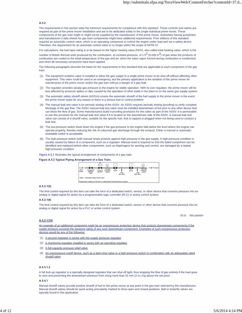
SR-18 Hide Legislative
A.5.2
The requirements in this section state the minimum requirements for compliance with this standard. These controls and valves arerequired as part of the prime mover installation and are to be dedicated solely to the single individual prime mover. Thesecomponents of the gas train might or might not be supplied by the manufacturer of the prime mover. Authorities having jurisdictionand manufacturer’s data sheets for gas train components might have additional requirements. Prior editions of this standardrequired an automatic control valve, which is an operating component to control the engine under load and not a safety device.Therefore, the requirement for an automatic control valve is no longer within the scope of NFPA 37.
For calculations, the fuel input rating is to be based on the higher heating value (HHV), also called total heating value, which is the
number of British thermal units produced by the combustion, at constant pressure, of 1 ft3 (0.028 m3) of gas when the products ofcombustion are cooled to the initial temperature of the gas and air, when the water vapor formed during combustion is condensed,and when all necessary corrections have been applied.
The following paragraphs describe the basis for the requirements in this standard that are applicable to each component of the gastrain:
(1) The equipment isolation valve is installed to allow the gas supply to a single prime mover to be shut off without affecting otherequipment. This valve could be used in an emergency, but the primary application is the isolation of the prime mover formaintenance of the prime mover and/or the gas train without a danger of a gas leak.
(2) The regulator provides steady gas pressure to the engine for stable operation. With its own regulator, the prime mover will beless affected by pressure spikes or dips caused by the operation of other loads in the plant or on the same gas supply system.
(3) The automatic safety shutoff valves (ASSVs) ensure the automatic shutoff of the fuel supply to the prime mover in the eventthe prime mover stops for any reason or there is a serious fuel or control problem.
(4) The manual leak test valve is for periodic testing of the ASSV. An ASSV requires periodic testing (proofing) to verify completeblockage of the gas flow. The ASSV manual leak test valve must be installed downstream of but prior to any other device thatcan block the flow of gas. Some manufacturers build in proofing provisions for this valve as part of the ASSV; it is permissibleto use this provision for the manual leak test valve if it is located on the downstream side of the ASSV. A manual leak testvalve can consist of a shutoff valve, suitable for the specific fuel, that is capped or plugged when not being used to conduct aleak test.
(5) The low-pressure switch shuts down the engine if the gas pressure to the engine falls below the level where the engine canoperate properly, thereby reducing the risk of unburned gas discharge through the exhaust. Either a manual or automaticresettable switch is acceptable.
(6) The high-pressure switch (with manual reset) protects against high pressure in the gas supply. A high-pressure condition isusually caused by failure of a component, such as a regulator. Manual reset is required so that the failed component can beidentified and replaced before other components, such as diaphragms for sensing and control, are damaged by a repeathigh-pressure condition.
Figure A.5.2 illustrates the typical arrangement of components of a gas train.
Figure A.5.2 Typical Piping Arrangement of a Gas Train.
A.5.2.1(5)
The limit control required by this item can take the form of a dedicated switch, sensor, or other device that converts pressure into ananalog or digital signal for action by a programmable logic controller (PLC) or active control system.
A.5.2.1(6)
The limit control required by this item can take the form of a dedicated switch, sensor or other device that converts pressure into ananalog or digital signal for action by a PLC or active control system.
A.5.2.1(10)
An example of an additional component might be an overpressure protection device that protects downstream components if thesupply pressure exceeds the pressure rating of any such downstream component. Examples of such overpressure protectiondevices would be any of the following:
(1) A second regulator in series with the supply pressure regulator
(2) A monitoring regulator installed in series with an operating regulator
(3) A full-capacity pressure relief valve
(4) An overpressure cutoff device, such as a slam-shut valve or a high-pressure switch in combination with an adequately ratedshutoff valve
A.5.3.1.2
A full lock-up regulator is a specially designed regulator that can shut off tight, thus stopping the flow of gas entirely if the load goesto zero and preventing the downstream pressure from rising more than 51 mm (2 in.) Hg above the set point.
A.5.4.1
Manual shutoff valves provide positive shutoff of fuel to the prime mover at any point in the gas train selected by the manufacturer.Manual shutoff valves should be quick acting and plainly marked to show open and closed positions. Ball or butterfly valves aretypically found in this application.
http://submittals.nfpa.org/TerraViewWeb/ContentFetcher?contentId=37.d...
4 of 12 5/6/2014 4:14 PM
A.5.4.1.3
At least one of the manual shutoff valves should be located in a remote location outside the fire hazard area of the prime mover foremergency shutdown purposes.
A.5.4.2
Equipment isolation valves are placed near the prime mover as a preventative measure. Such a valve is to be used whenevermaintenance is to be performed on the prime mover and/or associated gas train, in cases where there is a suspected leak in thegas train and fuel needs to be immediately shut off, and whenever lockout/tagout is required for safe operation. This valve shouldshut down fuel supply to only the one prime mover, isolating it from the gas supply and allowing other appliances to continueoperating. If located outside the prime mover fire hazard area, this valve can also provide the emergency shutdown capabilityrequired in 5.4.1.3.
A.5.4.3
ASSVs are quick-acting valves that shut off fuel when the prime mover stops or when the prime mover needs to be automaticallystopped based on some other criteria such as an activated fire alarm or sprinkler system alarm.
A.5.4.3.1
It is permissible, but less desirable, to replace one of the ASSVs with one of the following valves if it will automatically shut off theflow of fuel within 1 second of the engine stopping:
(1) Carburetion valve. The carburetion valve is often referred to as the mixer or air/gas valve. The carburetion valve controls theair–fuel mixture by metering the fuel inlet based on the velocity of the air coming into the valve. If there is no air flow, thecarburetion valve shuts off the fuel.
(2) Zero governor–type regulating valve. Also referred to as a “zero pressure regulator” or “zero governor.” In the case of a venturimixer, a zero governor–type regulating valve is used. When used as a shutoff valve, it must be adjusted to provide zero fuelflow in the standby condition. Prime mover vacuum draws against a diaphragm, which opens the spring-loaded fuel inlet valve,causing fuel to flow.
(3) Auxiliary valve. This category would include any other types of valves that suit the purpose of providing positive fuel shutoffwithin 1 second of the prime mover stopping.
A.5.4.3.2
Paragraph 5.4.3.1 allows the use of a carburetion valve or zero governor–type regulating valve if the device automatically shuts offthe flow of gas. If one of those is used, there is no need to install a manual leak test valve since the engine side is vented toatmosphere.
A.5.4.4.3
It is permissible, but less desirable, to replace one of the ASSVs with a control valve, provided the valve can automatically shut offthe flow of fuel within the time limits specified in 5.4.4.1. The manufacturer’s decision to use a control valve as an ASSV should bea function of trapped gas volume downstream of the last ASSV. Where large volumes of trapped gas exist, engine shutdown time isincreased and the potential for increased equipment damage from an extended shutdown time becomes a primary factor in decidingbetween a dedicated ASSV and a substitute ASSV control valve.
A.5.4.4.4
The vent valve is used to depressurize the gas trapped between two ASSVs and thereby minimize the risk from any leaks thatmight occur in the gas train. Consequently, the valve should be sized to depressurize the trapped volume quickly.
A.5.4.4.5
Gas turbines are typically installed in a dedicated enclosure that provides acoustic isolation from the rest of the plant andincorporates high volume forced ventilation to manage the very high heat rates from the turbine casings [some portions of whichcan exceed 540ºC (1000ºF)]. Additionally, facilities that have multiple turbines can include a large building to provide weatherprotection for the equipment and personnel. The ability to isolate the fuel supply external to these enclosed spaces mitigatespotentially catastrophic flammable atmospheres within the enclosed spaces.
A.6.1
Liquid-fueled engines are those where fuel is delivered to the engine in liquid form. This chapter does not apply to propane storedas a liquid and utilized as a vapor. (See 4.1.1.4 and Chapter 5.)
A.6.2
Examples of Class I fuels are gasoline, gasohol, and alcohol.
A.6.2.2
Installation requirements in NFPA 30, Flammable and Combustible Liquids Code, that are applicable to NFPA 37 include minimumdistance from adjoining property lines, spacing, dikes, foundations, supports, depth and cover, anchorage, normal and emergencyvents, and testing.
A.6.3
Examples of liquid fuels other than Class I fuels are diesel fuel, fuel oils, jet fuel, and kerosene.
A.6.3.2.2
In regard to the exception to 6.3.2.2, fire codes have the following two principal objectives: to prevent fire and, when fire doesoccur, to limit the spread of smoke and fire in order to limit damage to life and property. One commonly accepted fire protection goalis to extinguish or control the fire before it reaches flashover or full room involvement. In other words, the philosophy is that theworst case should be to sacrifice the room or compartment where the fire occurs in order to protect the rest of the structure.
The provisions of this paragraph do not address the likelihood of a fire. Rather, they address limiting the spread of fire in order tolimit damage in the event of a fire. There are many sound fire protection engineering methods and techniques to evaluateequivalent protection. Some are computer-based and require many inputs, while others offer a method of understanding,evaluating, presenting, and comparing risks graphically.
A.6.3.2.3
The information in A.6.3.2.2 also applies to the exception to 6.3.2.3.
http://submittals.nfpa.org/TerraViewWeb/ContentFetcher?contentId=37.d...
5 of 12 5/6/2014 4:14 PM
A.6.3.5
Aboveground storage tanks designed and constructed in accordance with UL 2080, Fire Resistant Tanks for Flammable andCombustible Liquids, or UL 2085, Protected Aboveground Tanks for Flammable and Combustible Liquids, are not considered byNFPA 37 to be equivalent to the rooms described in 6.3.5 and 6.3.6.
The reason tanks listed to UL 2080 and UL 2085 are not equivalent to the rooms described in 6.3.5 and 6.3.6 is that the UL listingsand the construction of these tanks are directed at protecting the tank from exposure to an external fire. The enclosurerequirements in 6.3.5 and 6.3.6 are designed to protect the building from a fire in the fuel tank room.
A.6.3.5.4
See NFPA 30, Flammable and Combustible Liquids Code, section on ventilation.
A.6.3.6
Aboveground storage tanks designed and constructed in accordance with UL 2080, Fire Resistant Tanks for Flammable andCombustible Liquids, or UL 2085, Protected Aboveground Tanks for Flammable and Combustible Liquids, are not considered byNFPA 37 to be equivalent to the rooms described in 6.3.5 and 6.3.6.
The reason tanks listed to UL 2080 and UL 2085 are not equivalent to the rooms described in 6.3.5 and 6.3.6 is that the UL listingsand the construction of these tanks are directed at protecting the tank from exposure to an external fire. The enclosurerequirements in 6.3.5 and 6.3.6 are designed to protect the building from a fire in the fuel tank room.
A.6.3.6.5
See NFPA 30, Flammable and Combustible Liquids Code, section on ventilation.
A.6.5.7
Where crude or residual oils are utilized as engine fuel, it is sometimes necessary to heat the fuel above the flashpoint of certainlight fractions within the fuel for satisfactory handling and injection into the engine. This condition necessitates special storage,purifying, and heating systems.
A.6.8.1
Piping systems supplying liquid fuels should be designed to minimize piping failure. Several examples of methods for minimizingpiping failure are as follows:
(1) Welded pipe joints should be used where practical. Threaded couplings and bolted flanges should be assembled inaccordance with the manufacturer's requirements.
(2) If rigid metal piping is used, it should be designed to deflect with the engine in any direction. Properly designed flexibleconnectors are an alternative in high-vibration areas, such as between rigid pipe supply lines and manifolds or other points ofengine interface.
(3) Rigid piping connected directly to the engine should be supported so that failures will not occur due to the natural frequency ofthe piping coinciding with the rotational speed of the engine. Care should be taken in the design of pipe supports to avoidvibrations.
A.6.8.2.1
Flexible connectors can fail under fire exposure. This factor should be considered in the design of piping systems.
A.6.8.3
There are several ways to meet the requirements of this section. Shutoff mechanisms can be either manual or automatic.
Manual valves located away from the engine or outside of the engine room can be used as emergency shutoff devices. Solenoidvalves interlocked with other controls can also be used to shut off fuel supplies.
In the event of a fire, automatic valves utilizing fusible links have been used to shut off fuel supplies. The fusible element might be inthe valve handwheel or attached to a flexible wire and spring of a lever-operated valve. These valves are normally closed. They areheld open when the fusible element is intact.
An oil safety valve or antisiphon valve could be utilized to shut off the fuel supplies where the possibility of continued, undesirableflow of fuel by gravity or siphoning exists due to a pipe break. An oil safety valve requires a vacuum on its outlet to open and permitoil flow, thereby automatically stopping flow in the event of a pipe break. An oil safety valve will also stop oil flow in the event of agasket leak on a basket-type oil filter or strainer that prevents the oil pump on the engine from pulling a vacuum.
A.7.3
Piping systems supplying lubricating or hydraulic oil should be designed to minimize piping failure. Several examples of methods forminimizing piping failure are as follows:
(1) Welded pipe joints should be used where practical. Threaded couplings and bolted flanges should be assembled inaccordance with the manufacturer's requirements.
(2) Where practical, lubricating oil lines should use guard pipe construction, with the pressurized supply line located inside thereturn line.
(3) If rigid metal piping is used, it should be designed to deflect with the engine in any direction. Properly designed flexibleconnectors are an alternative in high-vibration areas.
(4) Rigid piping connected directly to the engine should be supported so that failures will not occur due to the natural frequency ofthe piping coinciding with the rotational speed of the engine.
A.8.1.1
The exhaust gas flow, engine manufacturer's recommendations, and user requirements should also be considered in the designand construction of engine exhaust systems.
http://submittals.nfpa.org/TerraViewWeb/ContentFetcher?contentId=37.d...
6 of 12 5/6/2014 4:14 PM
PCs [1]
SR-14 Hide Legislative
A.8.1.2
The “service” of an exhaust system includes any of the following:
(1) Exposure to heat (short-term and sustained high-temperature)
(2) Corrosive atmospheres (internal or external)
(3) Internal pressure (including possible explosion of unburned fuel)
(4) External forces (such as wind, weight of snow, dust or dirt accumulation, or seismic event)
A.8.1.4
Normally, this provision is met by the built-in strength of the system. However, it can also be accomplished by use of devices suchas relief valves, rupture discs, or their equivalent.
A.8.1.5
Low points are needed to provide a means of draining liquids that can accumulate in the exhaust system, including condensate,rainwater, or melted snow.
A.8.2.3.1
Exhaust systems should not terminate under structures (including loading platforms) or where exhaust gas entrainment intoventilation intakes might occur.
A.8.2.5.1
Calculations for exhausting engines and other appliances into the same flue can be complex and should only be performed byqualified persons. Factors that affect calculations include the uniqueness of the installation, the number of devices venting into theflue, the exhaust gas flow and temperature, and the size and height of the flue.
A.8.2.5.2
See A.8.2.5.1.
A.8.4
Exhaust systems with temperatures in this range might require special consideration as to the following:
(1) Choice of materials
(2) Provision for thermal expansion
(3) Clearances from combustible materials
(4) Other design details
A.9.2.1
In many installations, it is advisable to have a lower alarm point for parameters such as engine overspeed, high jacket watertemperature or high cylinder temperature, low oil level or pressure, and high oil temperature to alert operators of deterioratingoperating conditions prior to the automatic shutdown of the engine.
A.9.2.2
Hazardous locations might contain flammable or combustible vapors that could be of sufficient concentration to cause the engine tocontinue to run if the vapors are drawn into the engine through its intake.
A.9.3.1
In many installations it is advisable to have a lower alarm point for parameters such as engine overspeed, engine vibration, lowlubricating oil pressure, and high exhaust temperatures to alert operators of deteriorating operating conditions prior to the automaticshutdown of the engine. See ANSI B133.4, Gas Turbine Control and Protection Systems.
One method of shutting down a combustion gas turbine is by means of an emergency stop button provided at a remote location, inaddition to the normal remote stop button. The purpose of the emergency stop button is to shut off the fuel supply and electricalpower to the unit, leaving only essential lubricating oil and fire suppression services operational. The emergency stop button isusually colored red and conspicuously identified.
An emergency stop might differ from a normal remote stop by avoiding some shutdown sequences, such as a cool-down period.
Global SR-14 Hide Deleted
A.9.3.2
While Subsection 9.3.1 provides a list of devices required to shut down the engine in case of an emergency, Subsection 9.3.2provides a list of control features needed to ensure the safety of the engine.
http://submittals.nfpa.org/TerraViewWeb/ContentFetcher?contentId=37.d...
7 of 12 5/6/2014 4:14 PM

A.10.2
Emergency instructions should be established for all operations involved with engines. At a minimum, a written fire emergency planshould be developed that includes the following:
(1) Response to the fire alarms and fire system supervisory alarms
(2) Notification of personnel identified in the plan
(3) Evacuation of employees not directly involved in fire-fighting activities for the fire area
(4) Coordination with security forces or other designated personnel to admit public fire department
(5) Fire extinguishment activities
(6) Periodic drills to verify viability of the plan
(7) Control room operators' activities during fire emergencies
A.10.2.1
Procedures for the operation of the engine during abnormal operating conditions should be developed also.
A.10.3
Training for operating and maintenance procedures will vary by system type, size, and complexity. The manufacturer'srecommendations for training will prevail as a minimum requirement, as amended by the owner or the authority having jurisdiction.
Training can range from reading and understanding an instruction manual for very small systems to undergoing formalizedclassroom and hands-on training for larger systems. Of particular importance is training on emergency shutdown procedures.Operating personnel should be knowledgeable of and capable of operation of all emergency shutdown procedures.
A.11.1
The fire risk evaluation should include, but not be limited to, the following:
(1) Characteristics of the engine
(2) Layout of the engine installation, including engine auxiliary equipment
(3) Adjacent exposures, including structures, operations, and other engine installations
The fire risk evaluation should also consider operating requirements, such as whether the engine installation is for emergency use.
The fire risk evaluation should result in a list of recommended fire protection features, separation or control of common and specialhazards, and the detection and suppression of fires. The fire risk evaluation should at least consider the following:
(1) Life safety requirements
(2) The type and quantity of combustible materials involved, including engine fuel, lubricating oil, and insulating materials
(3) Potential ignition sources, including electrical components and hot metal surfaces
(4) Oxygen and ventilation sources
(5) The location of the engine
(6) Operational considerations, including expected maximum and minimum ambient conditions
(7) The method of fuel transfer
(8) The importance of the engine to operations
(9) Response time and capabilities of the local fire department or fire brigade
(10) Fire experience
A.11.2.1
Where portable extinguishers are provided, personnel involved in the installation and operation of engines should be trained in theiruse.
http://submittals.nfpa.org/TerraViewWeb/ContentFetcher?contentId=37.d...
8 of 12 5/6/2014 4:14 PM
A.11.3.1
For each enclosure requiring fire protection, fire detectors are intended to provide timely detection of a fire and might allow earlyintervention that can limit damage. Selection of the type of fire detector to be used should be based on the application and engineequipment arrangement. For example, the use of smoke detection might be a problem due to false actuations caused by exhaustgases during engine operation. If heat-activated fire detectors are used, temperature ratings should be based on the maximumambient temperatures of the enclosure that can be expected under normal operating conditions, so that fire detectors do not actuatedue solely to the heat produced when the engine is operating. Typically, detectors are selected to actuate at about 38°C (55°F)above the maximum ambient temperature.
For more rapid detection of fires, the use of flame detectors can be considered for early warning, engine shutdown, or firesuppression system activation. The installation of these detectors should be evenly distributed across the hazard to allow for properdetection throughout the enclosure.
In all installations, the detectors should be strategically positioned near specific hazards but away from high-ventilation flow pathsthat could disperse heat and delay detection of a fire and away from heat-producing devices, such as heaters, that couldunnecessarily set off detectors. The detectors should be mounted firmly to rigid structures and in areas where minimum vibration ispresent.
Where a fire suppression system is also being used and inadvertent actuation of the suppression system is a concern,consideration should be given to cross-zoning the detectors such that at least two detectors that are installed in different detectionzones have to trip in order for the suppression system to activate.
In addition to the detectors, the installation of the other components of the fire detection and alarm system also need to addressed.Visual and audible notification devices should be located where they will be easily seen and heard. Depending on the installation,this might be both inside and outside of the engine enclosure.
Hazardous vapor detection can be appropriate where vapor leaks might be expected. This type of detector can identify the need forengine fuel system shutdown and possible inerting of the engine enclosure via a fire suppression system discharge.
Components that should be considered when installing a fire detection and alarm system, especially when used in conjunction witha fire suppression system, should include at least the following:
(1) Fire alarm strobe and horns positioned in highly visible and audible areas of the engine enclosure on the inside and outside ofthe enclosure, where applicable
(2) Warning signs positioned on enclosure access doors where a fire suppression system has been installed
(3) Manual discharge stations positioned near enclosure access doors where a fire suppression system has been installed
(4) Manual lockout stations for engine maintenance purposes positioned near enclosure access doors where a fire suppressionsystem has been installed
(5) Where required for the fire suppressant being used, predischarge timers, located in the fire control panel, that allow a timedelay of at least 30 seconds between fire alarm strobe and horn annunciation and fire suppression system discharge
A.11.4.1.1
Upon installation, all fire suppression systems, including any associated fire detection and alarm system, should be fully tested inaccordance with the applicable NFPA standards. Applicable NFPA standards might require a full discharge or concentration test toensure the fire suppression system operates properly or might allow for some other means, such as a room pressurization test, toprove the capabilities of the system.
http://submittals.nfpa.org/TerraViewWeb/ContentFetcher?contentId=37.d...
9 of 12 5/6/2014 4:14 PM
A.11.4.2.1
The following factors should be considered in determining whether to provide an automatic fuel shutdown valve that stops the flowof fuel when the engine enclosure fire suppression system activates:
(1) Whether the engine is running.
(2) Whether the engine is constantly attended.
(3) If more than one source of emergency power is available, whether it is possible to shut down one source without adverselyaffecting the supply of emergency power. In this case, the automatic valve should be provided.
(4) If more than one source of emergency power is available, the likelihood that a fire involving one source will spread to the othersources. If the fire is likely to spread to other sources or exposures, an automatic stop valve should be provided.
(5) If the engine is for emergency use, whether the following could cause accidental operation of the fire suppression system. Ifthe fire detection system is tied to the fire suppression system, shutdown of the emergency use engine could occur at a timewhen shutdown would be unacceptable. Provisions should be considered to prevent the following:
(a) Accidental activation of the fire detection system.
(b) Prolonged operation of the engine during a power outage, which can produce extreme temperatures or conditions notfound during system commissioning, testing, and inspection. For example, heat detectors might activate if placed tooclose to exhaust manifolds, smoke detectors might activate after animal nests are built touching exhaust piping, andoptical flame detectors might detect lightning or other phenomenon not present during system commissioning.
(c) Electrical voltage irregularities or transients in the outside power supply system, which might necessitate emergencypower and might cause unpredictable operation of the fire detection system.
(6) Even though an engine is for emergency use and it might be desirable to maintain emergency power during a fire, whether itmight not be possible to keep the engine running even if the fuel line is not closed because of one or more of the following:
(a) Gaseous fire suppression systems that require the closure of all vents, doors, and dampers, the closure of which canprevent the engine from receiving radiator cooling air, combustion air, or both, and subsequently can cause the engine tostop running or become damaged
(b) Fires involving motor fuel that can generally cause high temperatures in the engine enclosure that are likely to damage ordestroy electrical distribution cabling intended to distribute emergency power
(c) Fires involving motor fuel that are likely to damage or destroy the fuel line, preventing the engine from having anadequate supply of fuel and resulting in loss of emergency power
(7) Whether the location of the engine can affect the risk of spread of fire or smoke to, or within, the rest of the building. An engineon a roof would present a different hazard from an engine in a basement. The need for automatic fuel shutoff is greater in aninstallation that poses an increased risk to the building or its contents.
(8) Whether a fire during routine testing can cause damage that will take months to repair. Most operation of engines foremergency use occurs during routine testing, when normal power is also available. During such repair time, emergency powermight not be available to some or all of the critical equipment or facilities. Even if an automatic fuel stop valve is determined topresent an unacceptable risk to an emergency-use engine, arrangements should be considered that would provide automaticfuel shutdown in the event of a fire during routine testing.
A.11.4.2.1.1
The option for emergency and constantly attended engines is whether to have the fire suppression system close the automaticvalve, not whether to install the valve. The automatic valve is required to meet other requirements of this standard, regardless ofwhether the fire suppression system closes it.
http://submittals.nfpa.org/TerraViewWeb/ContentFetcher?contentId=37.d...
10 of 12 5/6/2014 4:14 PM

SR-22 Hide Legislative
A.11.4.2.3
After the fire suppression system has extinguished the fire, the suppression agent and potentially toxic products of combustionshould be removed from the engine enclosure and the atmosphere sampled before personnel without air-breathing apparatus enterfor inspection or repairs. Removal is usually accomplished by dilution ventilation, using a combination of exhaust and make-up air.Removal can be accomplished by using either normal or mechanical ventilation.
Normal ventilation is natural movement of air through the enclosure or room by opening doors or windows. In instances whererooms or enclosures are inside larger structures, care should be taken to avoid introducing contaminants into other building areas.
Mechanical ventilation systems can consist of the normal ventilation system for the room or enclosure or a dedicated purge system.Exhaust air should discharge outside the structure, away from operable windows and outside air intakes.
In locating the exhaust air discharge, consideration should be given to both the engine enclosure and nearby structures. Chapter15, “Airflow Around Buildings,” of the ASHRAE 1997 Handbook — Fundamentals can be consulted for guidelines on exhaust airstack height and distance from other structures, as well as air intakes needed to provide adequate dilution and to avoid detrimentaleffects of downdrafts.
Make-up air and exhaust openings in the enclosure should be sized and located to minimize short-circuiting. Short-circuiting occurswhen make-up air flows directly from the inlet to the outlet without adequately sweeping through the enclosure. For suppressionagents heavier than air, make-up air should enter high and exhaust should leave low. For suppression agents lighter than air,make-up air should enter low and exhaust should leave high. In either case, inlets and outlets should ideally be on opposite sides ofthe enclosure.
Make-up air openings in the enclosure should be sized for relatively low velocities. With sufficiently low velocity, the incomingmake-up air tends toward “plug flow,” pushing contaminated air toward the exhaust. High-velocity incoming air would mix themake-up and contaminated airstreams, reducing the contaminant concentration of the exhausted air.
Exhaust air openings should likewise be sized for low velocities. Higher velocities tend to create a funnel effect, leaving dead zonesof contaminated air that is slow to be exhausted.
For guidance on calculating the time required to achieve a suitable atmosphere within the room or enclosure, refer to NFPA 92A ,Standard for Smoke-Control Systems Utilizing Barriers and Pressure Differences , NFPA 92B , Standard for Smoke ManagementSystems in Malls, Atria, and Large Spaces , or the ASHRAE and SFPE Design of Smoke Management Systems. For guidance indetermining allowable concentrations of contaminant, refer to material safety data sheets (MSDS) and permissible exposure limits(PEL) from OSHA.
A.11.4.3
Fire suppression system discharge durations should be held as long as the hazards of hot metal surfaces above the autoignitiontemperature and uncontrollable combustible fluid flow exist (consult manufacturer for applicable engine cool-down times). Testinghas shown this time requirement to be approximately 20 minutes for many areas, but it can be substantially longer. It has beenshown that the initial discharge will not usually hold for a 20-minute time period in most engine enclosures, and, under thesecircumstances, an added extended discharge is necessary to prevent potential fire reignition due to smoldering and heat soak.Where design concentrations still cannot be maintained effectively, an alternative system should be provided.
When foam suppression systems are used, full discharge tests should be completed to determine if the engine will be submerged.
Fencing with a maximum opening of 1300 mm2 (2 in.2) or other barriers should be used when openings in the protected engineenclosure are present.
A.11.4.4
Gaseous agent fire suppression systems can be used to extinguish engine equipment fires in either of the following two ways:
(1) Total flooding systems are used where there is a permanent enclosure around the fire hazard that is adequate to enable thedesign concentration to be built up and to be maintained for the period of time required to ensure the complete and permanentextinguishment of a fire for the specific combustible materials involved. For total flooding systems, potential leakage sourcesshould be included in the gaseous agent design quantities, which should include leakage through ventilation dampers. Usuallyventilation dampers are either gravity actuated (i.e., close when the ventilation fans automatically shut down upon gaseousagent discharge) or pressure actuated (i.e., close by means of counterweight and a pressure-operated latch that is activatedby the gaseous agent). Leakage from the interface between the enclosure walls and the foundation should also be taken intoconsideration. For engine enclosures where the normal temperature of the enclosure exceeds 93ºC (200ºF) or is below -18ºC(0ºF), gaseous agent levels should be adjusted as required by the appropriate NFPA standard or the manufacturer’sinstruction manual.
(2) Local application systems are used for the extinguishment of surface fires of combustible gases, liquids, or solids, where thefire hazard is not enclosed or where the enclosure does not conform to the requirements for a total flooding system. For localapplication systems, it is imperative that the entire fire hazard be protected. The hazard area should include all areas that aresubject to spillage, leakage, splashing, condensation, and so forth, and are of combustible materials that might extend a fireoutside the protected area or lead a fire into the protected area. This type of hazard could necessitate dikes, drains, ortrenches to contain any combustible material leakage. When multiple engine equipment fire hazards are in an area such thatthey are interexposing, provisions should be made to ensure that the hazards can be protected simultaneously, which couldinvolve subdividing the hazards into sections and providing independent protection to each section.
Gaseous agent fire suppression systems should generally be designed to have the capacity to supply two full discharges to avoidhaving to keep the engine shut down until the gaseous agent reservoir can be replenished, particularly after a minor fire oraccidental discharge. Two full discharges should use 90 percent of the total gaseous agent reservoir capacity as an optimumdesign; however, up to 95 percent is acceptable. For applications where ambient temperatures are above the normal operatingconditions of the gaseous agent reservoir, a shelter with ventilation openings or an equivalent alternative should be used. Whereambient temperatures are below the normal operating conditions of the gaseous agent reservoir, reservoir heaters (such asimmersion heaters) and instrument line heaters should be used or, where applicable, the reservoir can be superpressurized withnitrogen to maintain the required flows and pressures in a low-temperature environment.
Warning signs and safety instructions are required on some types of gaseous agent systems. The user should refer to theappropriate NFPA standards for those systems for detailed requirements.
http://submittals.nfpa.org/TerraViewWeb/ContentFetcher?contentId=37.d...
11 of 12 5/6/2014 4:14 PM
SR-11 Hide Legislative
SR-12 Hide Legislative
A.11.4.4.1
Where total flooding gaseous systems are used, the engine enclosure should be arranged for minimum leakage by automaticshutdown of fans and automatic closing of doors, ventilation dampers, and other openings. During operation of an engine, there is aneed for substantial amounts of cooling and ventilation air. This air flow will not stop immediately upon engine shutdown and shouldbe considered in the extinguishing system design.
A.11.4.4.1.1
Fire suppression system design concentrations and discharge durations should be held as long as the hazards of hot metalsurfaces above the autoignition temperature and uncontrollable combustible fluid flow exist. The manufacturer should be consultedfor applicable engine cool-down times. Testing has shown this time requirement to be approximately 20 minutes, but for manycases it can be substantially longer. It has been shown that the initial concentration usually will not hold for a 20-minute time periodin most engine enclosures, and under these circumstances an added extended discharge is necessary to prevent potential firereignition due to smoldering and heat soak. heavy-duty industrial engines, it can be substantially longer. Conversely, thin-walledturbines based on aircraft engine designs cool very quickly, once fuel flow terminates. Just as discharge time might need to beincreased for some heavy-duty designs, it is appropriate to reduce the discharge duration for aircraft engine-based turbines to lessthan 20 minutes, based on discharge tests. Information on fire tests that demonstrate the extinguishment time for a turbine designshould also be considered in determining the minimum discharge time. It is recommended that the minimum discharge time be noless than twice the time demonstrated to achieve fire extinguishment for the suppressant used. It has been shown that the initialconcentration usually will not hold for a 20-minute time period in most engine enclosures and under these circumstances anextended discharge time is necessary to prevent potential fire reignition due to smoldering and heat soak. Where designconcentrations still cannot be maintained effectively, an alternative system should be provided.
A.11.4.4.2
Fire suppression system discharge durations should be held as long as the hazards of hot metal surfaces above the autoignitiontemperature and uncontrollable combustible fluid flow exist. The manufacturer should be consulted for applicable engine cool-downtimes. Testing has shown this time requirement to be approximately 20 minutes, but for industrial many cases turbines it can besubstantially longer. Conversely, thin-walled turbines based on aircraft engine design cool very quickly, once fuel flow terminates.Just as discharge time might need to be increased for industrial turbine designs, it is appropriate to reduce the discharge durationfor aircraft engine–based designs to less than 20 minutes, based on discharge tests. Information on fire tests that demonstrate theextinguishment time for a turbine design should also be considered in determining the minimum discharge time. It is recommendedthat the minimum discharge time be no less than twice the time demonstrated to achieve fire extinguishment for the suppressantused. An extended discharge time is necessary to prevent potential fire reignition due to smoldering and heat soak.
A.11.4.5.1
Automatic sprinkler systems are considered to be effective in controlling lubricating oil fires. Sprinkler densities provided in thisstandard are based on Extra Hazard, Group 1 occupancy as defined in NFPA 13, Standard for the Installation of Sprinkler Systems.Automatic sprinkler protection designed as local protection for the engine in many cases provides better protection than sprinklerprotection installed only at the ceiling level, particularly in the case of pressurized lubricating oil fires.
Consideration should be given to providing local protection when the protected engine equipment is located in a high bay area.Delayed activation time or lack of water penetration could delay fire suppression from a ceiling system.
Local protection for engines can be accomplished using either a wet system or a single interlock pre-action deluge system with heatdetection. Detectors for actuation of a pre-action system should be located above the engine and around the system piping.
For diesel engine installations, the system piping should loop the engine at the height of the cylinder heads.
Because of the tight radial clearances on combustion gas turbines and the potential for rubbing of rotating parts and increaseddamage, it is advisable to use great care if using a sprinkler or water spray suppression system. Water from a ceiling or spotprotection system could effectively control a fire; however, gaseous suppression agents could be just as effective without thepotential for equipment damage when the system activates.
A.11.4.7
Water mist fire suppression systems need to be designed specifically for use with the size and configuration of the specific engineinstallation or enclosure being protected. Currently there is no generic design method recognized for water mist systems. Systemfeatures such as nozzle spacing, flow rate, drop size distribution, cone angle, and other characteristics need to be determined foreach manufacturer's system through full-scale fire testing to obtain a listing for each specific application and must be designed,installed, and tested in accordance with NFPA 750, Standard on Water Mist Fire Protection Systems.
http://submittals.nfpa.org/TerraViewWeb/ContentFetcher?contentId=37.d...
12 of 12 5/6/2014 4:14 PM

NFPA 37®, Standard for the Installation and Use of Stationary Combustion Engines and Gas Turbines, 2010 Edition
NFPA STANDARDS DEVELOPMENT SITESECOND DRAFT REPORTClosing Date: July 19, 2013 NOTE: All Public Comment must be received by 5:00 pm EST/EDST on the published Closing Date.
Quick Print
SR-21 Hide Legislative
SR-23 Hide Legislative
Annex B Informational References
B.1 Referenced Publications.
The documents or portions thereof listed in this annex are referenced within the informational sections of this standard and are notpart of the requirements of this document unless also listed in Chapter 2 for other reasons.
B.1.1 NFPA Publications.
National Fire Protection Association, 1 Batterymarch Park, Quincy, MA 02169-7471.
NFPA 13, Standard for the Installation of Sprinkler Systems, 2013 0 edition.
NFPA 20, Standard for the Installation of Stationary Pumps for Fire Protection, 2013 0 edition.
NFPA 30, Flammable and Combustible Liquids Code, 2012 edition.
NFPA 56PS, Standard for Fire and Explosion Prevention During Cleaning and Purging of Flammable Gas Piping Systems, 2014 2edition.
NFPA 68, Standard on Explosion Protection by Deflagration Venting, 2013 07 edition.
NFPA 92A , Standard for Smoke-Control Systems Utilizing Barriers and Pressure Differences , 2009 edition.
NFPA 92B , Standard for Smoke Management Systems in Malls, Atria, and Large Spaces , 2009 edition.
NFPA 92, Standard for Smoke Control Systems, 2012 edition.
NFPA 99, Standard for Health Care Facilities Code , 2012 edition.
NFPA 110, Standard for Emergency and Standby Power Systems, 2013edition.
NFPA 220, Standard on Types of Building Construction, 2012 edition.
NFPA 555, Guide on Methods for Evaluating Potential for Room Flashover, 2013 09 edition.
NFPA 750, Standard on Water Mist Fire Protection Systems, 2014 0 edition.
B.1.2 Other Publications.
B.1.2.1 ANSI Publications.
American National Standards Institute, Inc., 25 West 43rd Street, 4th floor, New York, NY 10036.
ANSI B133.4, Gas Turbine Control and Protection Systems, 2007.
ANSI B133.6, Procurement Standard for Gas Turbine Ratings and Performance, 1994.
ANSI Z21.21, Automatic Valves for Gas Appliances, 2005.
B.1.2.2 ASHRAE Publications.
American Society of Heating, Refrigerating, and Air-Conditioning Engineers, Inc., 1791 Tullie Circle, NE, Atlanta, GA 30329-2305.
ASHRAE, Handbook — Fundamentals, 1997.
ASHRAE and SFPE, Design of Smoke Management Systems, 1992.
B.1.2.3 ASTM Publications.
ASTM International, 100 Barr Harbor Drive, P.O. Box C700. West Conshohocken, PA 19428-2959.
ASTM SI 10, Standard for the Use of the International System of Units (SI): The Modern Metric System, 1997.
Global SR-23 Hide Deleted
B.1.2.4 CSA Publications.
Canadian Standards Association, 5060 Spectrum Way, Mississauga, ON, L4W 5N6, Canada.
CSA B149.6, Code for Digester Gas and Landfill Gas Installations for Piping Materials and Practices, 2011.
B.1.2.5 SAE Publications.
Society of Automotive Engineers, 400 Commonwealth Drive, Warrendale, PA 15096.
SAE J1349, Engine Power Test Code, Spark Ignition and Compression Ignition, 1990.
B.1.2.6 UL Publications.
Underwriters Laboratories Inc., 333 Pfingsten Road, Northbrook, IL 60062-2096.
UL 2080, Fire Resistant Tanks for Flammable and Combustible Liquids, 2000.
UL 2085, Protected Aboveground Tanks for Flammable and Combustible Liquids, 1997, revised 2010.
B.2 Informational References. (Reserved)
B.3 References for Extracts in Informational Sections. (Reserved)
http://submittals.nfpa.org/TerraViewWeb/ContentFetcher?contentId=37.d...
1 of 1 5/6/2014 4:15 PM
Public Comment No. 5-NFPA 37-2012 [ Section No. 2.3.4 ]
2.3.4 UL Publications. Underwriters Laboratories Inc., 333 Pfingsten Road, Northbrook, IL 60062-2096.
ANSI/UL 900, Standard for Air Filter Units, 2004 , with revisions through November 2009 2012 .
Statement of Problem and Substantiation for Public Comment
Update referenced standard to most recent edition as indicated.
Submitter Information Verification
Submitter Full Name: John Bender
Organization: UL LLC
Submittal Date: Wed Oct 24 13:05:03 EDT 2012
Committee Statement
Committee Action: Accepted
Resolution: See SR-1-NFPA 37-2013
Statement: The Technical Committee agrees with the update to this reference.
Copyright Assignment
I, John Bender, hereby irrevocably grant and assign to the National Fire Protection Association (NFPA) all and full rights in copyright in this Public Comment (including both the Proposed Change and the Statement ofProblem and Substantiation). I understand and intend that I acquire no rights, including rights as a joint author, in any publication of the NFPA in which this Public Comment in this or another similar or derivative form is used. I hereby warrant that I am the author of this Public Comment and that I have full power and authority to enter into this copyright assignment.
By checking this box I affirm that I am John Bender, and I agree to be legally bound by the above Copyright Assignment and the terms and conditions contained therein. I understand and intend that, by checking this box, I am creating an electronic signature that will, upon my submission of this form, have the same legal force and effect as a handwritten signature
Page 1 of 25National Fire Protection Association Report
4/26/2013http://submittals.nfpa.org/TerraViewWeb/ContentFetcher?commentParams=%28Comment...
Public Comment No. 7-NFPA 37-2012 [ Section No. 4.1.4 ]
4.1.4 Engines Located Outdoors. Engines and their weatherproof housings if provided, that are installed outdoors shall be located at least 1.5 m (5 ft) from openings in walls and at least 1.5 m (5 ft) from structures having combustible walls. A minimum separation shall not be required where either of the following conditions exist:
(1) All walls of the structure that are closer than 1.5 m (5 ft) from the engineenclosure have a fire resistance rating of at least 1 hour.
(2)
4.1.4.1 * The full scale fire tests shall be conducted in the vicinity of combustible walls constructed of materials with a level of combustibility not less than that of the materials intended to be present where the engine is to be located.
4.1.4.2 The full scale fire tests shall result in complete consumption of all combustible materials contained within the engine.
4.1.4.3 The full scale fire tests shall represent fire scenarios where the engine is operating and where it is not operating.
4.1.4.4 * Engines located outdoors shall be placed at a separation distance from the nearest combustible wall that is greater than the distance at which the fire tests have been conducted, to provide a margin of safety.
A.4.1.4.1 Combustible materials exhibit different levels of combustibility or of ignitability. Examples of combustible exterior wall materials include various types of siding, such as vinyl, wood and polypropylene, as well as different exterior wall coverings (such as particleboard), exterior insulation and finish systems and decorative laminates. It has been shown that these diverse combustible materials can have very different levels of fire performance or of ignitability (see for example, NFPA 555). Therefore, the full scale fire tests should be conducted in the presence of combustible materials that adequately represent the potential fire hazard to be expected where the engine is to beplaced.
A.4.1.4.4 If fire testing has demonstrated, for example, that a fire within the engine does not cause ignition of combustible walls at a certain separation distance it is important that the engine be placed at a separation distance greater than that at which the tests have been conducted. A reasonable margin of safety (for example 50%) should be provided to deal with the potential variability of the fire tests.
A.4.1.4(2) Calculation procedures, such as those given in NFPA 555, Guide on Methods for Evaluating Potential for Room Flashover, are useful tools to assess the probability of safe engine placement.
Additional Proposed Changes
* The weatherproof enclosure is constructed of noncombustible materials and it has been demonstrated that a fire within the enclosure will not ignite combustible materials outside the enclosure. Calculations or full scale tests, acceptable to the authority having jurisdiction, using the engine and its weatherproof housing, based on the criteria in 4.1.4.1 through 4.1.4.4, have demonstrated that a fire within the enclosure will not ignite combustible materials outside the enclosure.
Page 2 of 25National Fire Protection Association Report
4/26/2013http://submittals.nfpa.org/TerraViewWeb/ContentFetcher?commentParams=%28Comment...
File Name Description Approved
CommentNFPA_37Marcelo_Hirschler4_1_4.docx
Proposed Change to 4.1.4 and Substantiation.
CommentNFPA37Testing_of_generators_Fire_Mats_2011.pdfSupporting material
Statement of Problem and Substantiation for Public Comment
Page 3 of 25National Fire Protection Association Report
4/26/2013http://submittals.nfpa.org/TerraViewWeb/ContentFetcher?commentParams=%28Comment...
This section lacks the information an authority having jurisdiction needs to assess any reports provided by an engine manufacturer seeking to place engines close to combustible walls. There are no criteria for how to demonstrate that an engine fire will not ignite a combustible wall or for how close to the wall the engine can be placed. The proposed language provides that information without being a detailed test protocol and without ruling out the use of calculations as a tool.1. In view of the close proximity between homes that often install engines or generators to ensure uninterrupted electrical supply, clear criteria for engine placement are essential to permit adequate enforcement. NFPA 37 does not contain enforceable criteria. 2. This comment incorporates the wishes of the technical committee that NFPA 37 should not specify details of the full scale fire test procedure to be used for determining acceptable separation distances. This is reflected in the revised wording.3. This comment also accepts the wishes of the technical committee that calculation methods be retained as an option. This is reflected in the revised wording.4. This comment does not propose wording that would require specific test protocols but simply proposes wording that ensures a minimal level of safety, after the calculations or full scale fire tests have been conducted.5. This comment suggests the addition of the phrase “acceptable to the authority having jurisdiction” because that will ensure an “approved” level of safety. 6. If an engine burns it can cause the ignition of nearby combustible walls. Whether ignition of combustible walls occurs will depend primarily on three factors: (a) the amount and fire performance of the combustible materials in the engine and the engineering design of the engine and its enclosure, (b) the materials contained in the combustible walls present and (c) the distance between the engine and the combustible walls.7. Fire tests have demonstrated that fire tests with some engines can be more severe when the generator/engine is not operating because the associated cooling fan in the generator/engine can result in the extinguishment of the fire when the generator/engine is operating but not when the generator/engine is idle. This has been shown for at least two engine designs. (a) Jason Huczek (Southwest Research Institute) [“Custom Fire Testing of Power Generators for NFPA 37 Compliance”, at the NFPA 2010 Annual Meeting, Session T68, June 9, 2010] and (b) Marcelo Hirschler [“Testing of Residential Electrical Generators”, Fire and Materials Conf., San Francisco, CA, Jan. 31-Feb. 2, 2011, pp. 71-81, Interscience Communications, London, UK, attached].8. There can be no assurance that every generator/engine will be provided with an adequate fan. Therefore, full scale fire tests or calculations need to be conducted with both the engine operating and the engine idle.9. The full scale fire tests or calculations leading to the determination of the safe location distance need to be conducted in such a way that there is complete consumption of the combustible materials in the engine/enclosure to ensure that the full scale fire tests or calculations actually address the fire hazard. 10. If the full scale fire tests or calculations do not result in complete consumption of the combustible materials in the engine there can be no assurance that the results are fully representative of the actual fire hazard.11. There are different types of combustible wall materials that are in common use and the full scale fire tests need to be conducted using either the wall materials to be used in the actual installation or the combustible wall materials with the poorest fire performance. Fire tests have demonstrated that polypropylene siding is a more combustible wall material than either wood siding or vinyl (PVC) siding. Peak heat release rate data for polypropylene, wood and PVC siding materials are shown below.12. The distance between the engine and the combustible walls must provide be a reasonable margin of safety so that if the tests are conducted at a distance of, for example 1 ft., the engine enclosure should not be permitted to be placed closer than 1.5 ft. (i.e. a 50% margin of safety).13. This comment proposes the elimination of the requirement that the weatherproof enclosure be constructed of noncombustible materials because that is not an enforceable requirement and has long been ignored by manufacturers. For the vast majority of engines the weatherproof enclosures contain some combustible components (such as knobs, for example) and their presence or absence is of no consequence if a fire that destroys all combustible materials does not cause wall ignition, and that is the key issue.
Page 4 of 25National Fire Protection Association Report
4/26/2013http://submittals.nfpa.org/TerraViewWeb/ContentFetcher?commentParams=%28Comment...

Heat release rate of siding materials (calorimeter testing)Vinyl (PVC) siding: 187 kW/m2Cedar siding: 309 kW/m2Polypropylene siding: 546 kW/m2
A publication by Marcelo Hirschler that provided one example of a set of tests that could be used to analyze the safe placement of generators follows (figures have been omitted)
TESTING OF RESIDENTIAL ELECTRICAL GENERATORS
Marcelo M. HirschlerGBH International, US
ABSTRACT
It is becoming increasingly common to find electrical generators used to ensure continuity of residential electrical service. Such electrical generators are usually placed as far away as possible from the combustible walls of homes. However, homeowners want to maximize the use of their yards/gardens/patios and prefer to minimize such separations.
NFPA 37 requires that generators be placed at least 1.5 m from combustible walls unless tests have demonstrated that a fire within the generator enclosure will not ignite combustible materials outside the enclosure, while US codes require only a separation of 1.5 m between walls of residences.
In this project a series of fire scenarios were identified which would represent the most extreme conditions under which a generator would have the potential to cause ignition of nearby combustible siding. The generator, containing an internal combustion gas-fueled engine, was placed within an open alcove-like enclosure consisting of three “walls” lined with non fire retarded polypropylene, simulating polypropylene siding. The walls were placed at a distance of 0.3 m from the generator.
Tests were conducted with generators fed by natural gas and with ones fed by propane. Temperatures were measured on the walls, inside the generator and on the open side of the alcove, via thermocouples. Heat fluxes were assessed on the walls and open side. Heat and smoke release was also assessed.
In none of the tests did ignition of polypropylene on the walls occur. In order to allow for a reasonable safety margin, it was concluded that the electrical generators tested were suitable for installation within 0.45 m of combustible walls. The most severe scenario has been shown to be when the engine and fan stop after running for a while and then ignition occurs and all combustibles can burn, to a degree that is a function of their fire performance.
INTRODUCTION
In recent years the use of generators for residences has become common due to the interest by homeowners to ensure uninterrupted power supply. Such generators are normally placed outside residences and connected so that they provide home electricity within moments of a power outage.
NFPA has had a standard for installation and use of combustion engines since the early 1900s and, in 2010, issued the latest edition of NFPA 37, Standard for the Installation and Use of Stationary Combustion Engines and Gas Turbines [1]. This document contains the following requirement:
“4.1.4 Engines Located Outdoors. Engines, and their weatherproof housings if provided,
Page 5 of 25National Fire Protection Association Report
4/26/2013http://submittals.nfpa.org/TerraViewWeb/ContentFetcher?commentParams=%28Comment...
that are installed outdoors shall be located at least 1.5 m (5 ft) from openings in walls and at least 1.5 m (5 ft) from structures having combustible walls. A minimum separation shall not be required where the following conditions exist: (1) The adjacent wall of the structure has a fire resistance rating of at least 1 hour.(2)* The weatherproof enclosure is constructed of noncombustible materials and it has been demonstrated that a fire within the enclosure will not ignite combustible materials outside the enclosure.”
Associated annex commentary: “A.4.1.4 (2) Means of demonstrating compliance are by means of full-scale fire tests or by calculation procedures, such as those given in NFPA 555, Guide on Methods for Evaluating Potential for Room Flashover [2].”
A requirement that stationary generators be maintained in accordance with NFPA 37 is included in the Uniform Fire Code (NFPA 1[3]). Another requirement that permanently installed equipment powered by internal combustion engines be installed in accordance with NFPA 37 is included in the International Fuel Gas Code (IFGC [4[), which is, in turn, referenced by the International Fire Code [5].
It is very unusual in the USA for residential exterior walls to exhibit fire resistance ratings of 1 hour, since residences tend to have “combustible construction”. Moreover, homes are often very close to each other, so that a 1.5 m separation from both the home associated with the generator and the neighboring home constitutes a burden for the homeowner, who may not be able to install generators. However, the vague language results in generators being normally installed with separation distances of at least 1.5 m from homes. The fire safety will be a function of generator design and of the related materials of construction.
EXPERIMENTAL
Small scale material tests, using the cone calorimeter, ASTM E 1354 [6], are an excellent way of choosing materials that have low heat release and good fire performance. One goal is to try to minimize the use of materials that exceed the International Fire Code requirement for large waste containers placed within 1.5 m of combustible walls: that the materials exhibit a peak heat release rate not exceeding 300 kW/m², when tested at an initial test heat flux of 50 kW/m², in the horizontal orientation. However, even for materials that comply with this goal, it is still necessary to ensure that fires will not ignite the wall.
In one project, conducted at the Department of Fire Technology of the Southwest Research Institute, full scale tests were conducted to assess the potential for a fire originating inside a generator to ignite nearby combustible walls. The siding material with the poorest fire performance in use in the USA is polypropylene (PP) siding. Each test scenario involved a generator inside a three wall corner. The walls were of lumber and gypsum wallboard construction covered with sheets of thin non FR PP sheets, simulating the siding. Each wall was 2.44 m (8 ft) high and 1.83 m (6 ft) long. The walls were placed 0.3 m (1 ft) from the generator. The entire assembly was set up directly under a 3 x 3 m (10 × 10 ft) calorimetry exhaust hood. During testing, the generator was placed under load by connecting it to a load bank, able to provide a 30 kW load. The generator exhaust was positioned such that the exhaust pointed towards the open side, in accordance with all manufacturers’ installation instructions.
Generators have safety features that turn the engine off if a gas leak occurs; the maximum gas leak that allows generator operation without it turning off was used, so that the worst case scenario was considered.
Instrumentation included 20 thermocouples, 4 placed inside the generator and 4 placed outside on each of the three walls and 4 on the open side. Additionally a heat flux gauge was placed facing the center of each generator side. Heat and smoke release from the tests were measured in the duct connected to the exhaust hood, with heat release by oxygen consumption calorimetry and smoke released with a white light source/detector, using the techniques described in ASTM E 2067 [7], commonly used for large scale tests.
Page 6 of 25National Fire Protection Association Report
4/26/2013http://submittals.nfpa.org/TerraViewWeb/ContentFetcher?commentParams=%28Comment...

Figure 1: Position of heat flux gauges and thermocouples on generator and polypropylene walls
TESTS AND RESULTS
A significant amount of summary data from all tests can be found in Table 1. All the generators used were gas-fed residential standby generators with two compartments: one for the engine and one for controls. The generators weighed 245 kg (540 lb), of which 13.7 kg (30.3 lb) were combustible materials.
Test 1 - A natural gas generator was run continuously under high external load (50 A). The generator turned itself off after just over 34 minutes, due to overheating of the oil temperature (in view of the excessive load imposed), without any ignition occurring in the engine or on the wall. Temperatures and heat fluxes remained fairly steady and not unusually high. The peak heat release rate measured was 55 kW and the total smoke released was 16 m².
Test 2 – Unplanned test, where the natural gas generator was run while monitoring the oil temperature to determine the maximum external load that will not cause the generator to overheat and turn itself off. A thermocouple was installed on the oil dip stick, to monitor the oil temperature, in order to establish a suitable external load, that at steady state, would not cause the engine oil to reach a temperature that would activate the engine overheat feature, which shuts down the engine. The external load established was 19 A, and this load was used for the other tests. No ignition occurred in the engine or on the wall. Temperature and heat flux data were unremarkable. Heat and smoke release was not measured.Test 9 – This test was intended as a repeat of test 1, but with a propane generator. A propane generator was monitored while running for 45 min with a 19 A external load. After 45 min various trials were conducted increasing and decreasing the electrical load which caused the engine to start and stop. The test was terminated at 52 min. No ignition of any kind occurred. Temperature and heat flux data were unremarkable. The peak heat release rate measured was 32 kW and the total smoke released was 2 m².
Test 3 – A natural gas generator was run under an external load of 19 A; natural gas was allowed to leak into the generator control compartment by diverting the gas line within the compartment, as close to the generator floor as practicable. The gas leak was the maximum gas leak (15 ft³/h; 1.2 x 10⁻⁴ m³/s) which would not activate the generator safety feature. After 3 min of the generator running with the gas leak, electric matches, which had been placed near the leak, were activated externally to attempt ignition. The test was
Page 7 of 25National Fire Protection Association Report
4/26/2013http://submittals.nfpa.org/TerraViewWeb/ContentFetcher?commentParams=%28Comment...
continued until all temperatures and heat fluxes were steady state. The test was terminated at 15.5 min. No ignition occurred inside the engine or on the wall. Temperature and heat flux data were unremarkable. The peak heat release rate measured was 27 kW and the total smoke released was 3 m².
Test 5 – This test was intended to simulate the accidental presence of external combustibles (such as leaves, branches, the unit manual and its associated bag, or others) which could have fallen inside the unit within the control compartment near the battery (which has a plastic casing). This was done by placing a plastic bag (with 40 sheets of standard white printer paper [8.5 x 11 in.; 216 x 279 mm] inside) on top of the battery casing, near the unit floor, inside the control compartment. The combustibles were ignited externally with an electric match. A natural gas generator was kept running for 15 min with a 19 A external load. After 15 min, an external natural gas leak source was directed into the control compartment, flowing once more at 15 ft³/h (1.2 x 10⁻⁴ m³/s). The gas leak was directed just above the battery, which is where the plastic bag had been placed The gas was ignited using electric matches and allowed to continue burning for 10 s. The generator was left on and under load for the entire test. Ignition of the gas occurred, which provided an ignition source for the plastic bag and paper sheets. The data was monitored for 23 min to ensure steady state. Upon completion of the test, the plastic bag and paper sheets had suffered slight discoloration and charring in the area of flame impingement. No damage to the interior of the generator was observed. Temperature and heat flux data were unremarkable. The peak heat release rate measured was 33 kW and the total smoke released was 1 m².
Test 6 - This test, like test 5, was intended to simulate the accidental presence of external combustibles (such as leaves, branches, the unit manual and its associated bag, or others) which could have fallen inside the unit or an electrical fault within the engine compartment near the electrical equipment and wiring. This was done by placing an identical plastic bag to the one used in test 5, also with 40 sheets of paper inside, by the electrical equipment near the unit floor, inside the engine compartment. A natural gas generator was kept running for 15 min with a 19 A external load. After 15 min, an external natural gas leak source was directed into the engine compartment, flowing once more at 15 ft³/h (1.2 x 10⁻⁴ m³/s). The gas leak was directed near the electrical equipment, which is where the plastic bag had been placed The gas was ignited using electric matches and allowed to continue burning for 10 s. The generator was left on and under load for the entire test. Ignition of the gas occurred, which provided an ignition source for the plastic bag and paper sheets. The data was monitored for 35 min to ensure steady state. Upon completion of the test, the plastic bag and paper sheets had been completely consumed and only ashes remained. Minimal discoloration but no significant burning was observed in the interior of the generator. Temperature and heat flux data were unremarkable. The peak heat release rate measured was 32 kW and the total smoke released was 30 m².
Test 7 – This test was intended as a repeat of test 5, but with a propane generator. In view of the much longer extension of a propane flame compared to a natural gas flame, the gas flow rate was set at 2.5 ft³/h (2.0 x 10⁻⁵ m³/s).The combustibles were ignited externally with an electric match. A propane generator was kept running for 15 min with a 19 A external load. After 15 min, an external propane leak source was directed into the control compartment, flowing at 2.5 ft³/h (2.0 x 10⁻⁵ m³/s). The gas leak was directed just above the battery, which is where the plastic bag had been placed The gas was ignited using electric matches and allowed to continue burning for 10 s. The generator was left on and under load for the entire test. Ignition of the gas occurred, which provided an ignition source for the plastic bag and paper sheets. The data was monitored for 22 min to ensure steady state. Upon completion of the test, the plastic bag and paper sheets had suffered slight discoloration and charring in the area of flame impingement. No damage to the interior of the generator was observed. Temperature and heat flux data were unremarkable. The peak heat release rate measured was 32 kW and the total smoke released was 10 m².
Test 8 – This test was intended as a repeat of test 6, but with a propane generator. Again, the propane gas flow rate was set at 2.5 ft³/h (2.0 x 10⁻⁵ m³/s).The combustibles were ignited externally with an electric match. An identical plastic bag to the one used in other
Page 8 of 25National Fire Protection Association Report
4/26/2013http://submittals.nfpa.org/TerraViewWeb/ContentFetcher?commentParams=%28Comment...
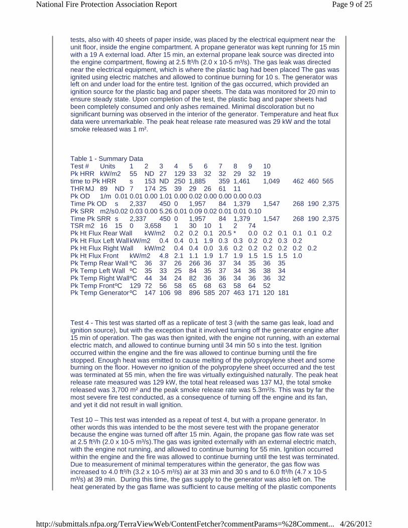
tests, also with 40 sheets of paper inside, was placed by the electrical equipment near the unit floor, inside the engine compartment. A propane generator was kept running for 15 min with a 19 A external load. After 15 min, an external propane leak source was directed into the engine compartment, flowing at 2.5 ft³/h (2.0 x 10⁻⁵ m³/s). The gas leak was directed near the electrical equipment, which is where the plastic bag had been placed The gas was ignited using electric matches and allowed to continue burning for 10 s. The generator was left on and under load for the entire test. Ignition of the gas occurred, which provided an ignition source for the plastic bag and paper sheets. The data was monitored for 20 min to ensure steady state. Upon completion of the test, the plastic bag and paper sheets had been completely consumed and only ashes remained. Minimal discoloration but no significant burning was observed in the interior of the generator. Temperature and heat flux data were unremarkable. The peak heat release rate measured was 29 kW and the total smoke released was 1 m².
Table 1 - Summary DataTest # Units 1 2 3 4 5 6 7 8 9 10Pk HRR kW/m2 55 ND 27 129 33 32 32 29 32 19time to Pk HRR s 153 ND 250 1,885 359 1,461 1,049 462 460 565THR MJ 89 ND 7 174 25 39 29 26 61 11Pk OD 1/m 0.01 0.01 0.00 1.01 0.00 0.02 0.00 0.00 0.00 0.03Time Pk OD s 2,337 450 0 1,957 84 1,379 1,547 268 190 2,375Pk SRR m2/s0.02 0.03 0.00 5.26 0.01 0.09 0.02 0.01 0.01 0.10Time Pk SRR s 2,337 450 0 1,957 84 1,379 1,547 268 190 2,375TSR m2 16 15 0 3,658 1 30 10 1 2 74Pk Ht Flux Rear Wall kW/m2 0.2 0.2 0.1 20.5 * 0.0 0.2 0.1 0.1 0.1 0.2Pk Ht Flux Left WallkW/m2 0.4 0.4 0.1 1.9 0.3 0.3 0.2 0.2 0.3 0.2Pk Ht Flux Right Wall kW/m2 0.4 0.4 0.0 3.6 0.2 0.2 0.2 0.2 0.2 0.2Pk Ht Flux Front kW/m2 4.8 2.1 1.1 1.9 1.7 1.9 1.5 1.5 1.5 1.0Pk Temp Rear Wall ºC 36 37 26 266 36 37 34 35 36 35Pk Temp Left Wall ºC 35 33 25 84 35 37 34 36 38 34Pk Temp Right WallºC 44 34 24 82 36 36 34 36 36 32Pk Temp FrontºC 129 72 56 58 65 68 63 58 64 52Pk Temp GeneratorºC 147 106 98 896 585 207 463 171 120 181
Test 4 - This test was started off as a replicate of test 3 (with the same gas leak, load and ignition source), but with the exception that it involved turning off the generator engine after 15 min of operation. The gas was then ignited, with the engine not running, with an external electric match, and allowed to continue burning until 34 min 50 s into the test. Ignition occurred within the engine and the fire was allowed to continue burning until the fire stopped. Enough heat was emitted to cause melting of the polypropylene sheet and some burning on the floor. However no ignition of the polypropylene sheet occurred and the test was terminated at 55 min, when the fire was virtually extinguished naturally. The peak heat release rate measured was 129 kW, the total heat released was 137 MJ, the total smoke released was 3,700 m² and the peak smoke release rate was 5.3m²/s. This was by far the most severe fire test conducted, as a consequence of turning off the engine and its fan, and yet it did not result in wall ignition.
Test 10 – This test was intended as a repeat of test 4, but with a propane generator. In other words this was intended to be the most severe test with the propane generator because the engine was turned off after 15 min. Again, the propane gas flow rate was set at 2.5 ft³/h (2.0 x 10⁻⁵ m³/s).The gas was ignited externally with an external electric match, with the engine not running, and allowed to continue burning for 55 min. Ignition occurred within the engine and the fire was allowed to continue burning until the test was terminated. Due to measurement of minimal temperatures within the generator, the gas flow was increased to 4.0 ft³/h (3.2 x 10⁻⁵ m³/s) air at 33 min and 30 s and to 6.0 ft³/h (4.7 x 10⁻⁵ m³/s) at 39 min. During this time, the gas supply to the generator was also left on. The heat generated by the gas flame was sufficient to cause melting of the plastic components
Page 9 of 25National Fire Protection Association Report
4/26/2013http://submittals.nfpa.org/TerraViewWeb/ContentFetcher?commentParams=%28Comment...
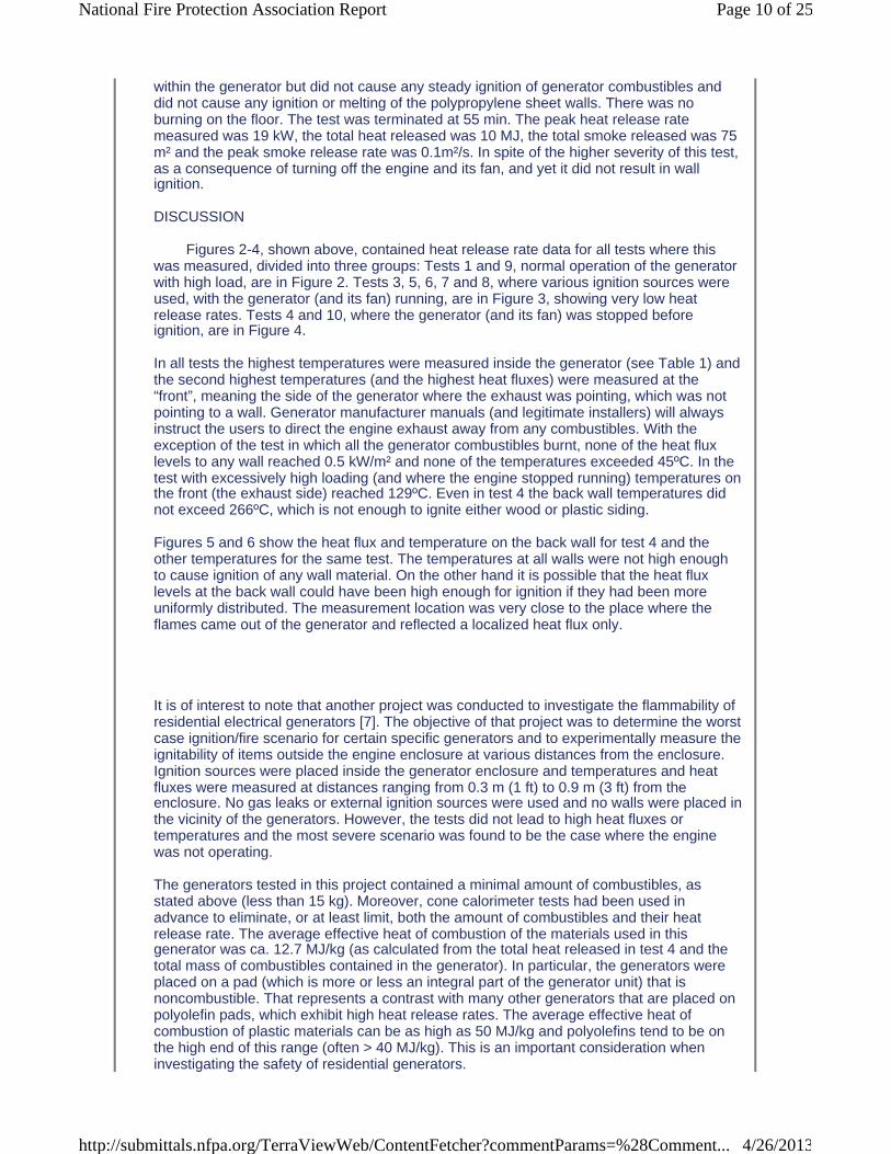
within the generator but did not cause any steady ignition of generator combustibles and did not cause any ignition or melting of the polypropylene sheet walls. There was no burning on the floor. The test was terminated at 55 min. The peak heat release rate measured was 19 kW, the total heat released was 10 MJ, the total smoke released was 75 m² and the peak smoke release rate was 0.1m²/s. In spite of the higher severity of this test, as a consequence of turning off the engine and its fan, and yet it did not result in wall ignition.
DISCUSSION
Figures 2-4, shown above, contained heat release rate data for all tests where this was measured, divided into three groups: Tests 1 and 9, normal operation of the generator with high load, are in Figure 2. Tests 3, 5, 6, 7 and 8, where various ignition sources were used, with the generator (and its fan) running, are in Figure 3, showing very low heat release rates. Tests 4 and 10, where the generator (and its fan) was stopped before ignition, are in Figure 4.
In all tests the highest temperatures were measured inside the generator (see Table 1) and the second highest temperatures (and the highest heat fluxes) were measured at the “front”, meaning the side of the generator where the exhaust was pointing, which was not pointing to a wall. Generator manufacturer manuals (and legitimate installers) will always instruct the users to direct the engine exhaust away from any combustibles. With the exception of the test in which all the generator combustibles burnt, none of the heat flux levels to any wall reached 0.5 kW/m² and none of the temperatures exceeded 45ºC. In the test with excessively high loading (and where the engine stopped running) temperatures on the front (the exhaust side) reached 129ºC. Even in test 4 the back wall temperatures did not exceed 266ºC, which is not enough to ignite either wood or plastic siding.
Figures 5 and 6 show the heat flux and temperature on the back wall for test 4 and the other temperatures for the same test. The temperatures at all walls were not high enough to cause ignition of any wall material. On the other hand it is possible that the heat flux levels at the back wall could have been high enough for ignition if they had been more uniformly distributed. The measurement location was very close to the place where the flames came out of the generator and reflected a localized heat flux only.
It is of interest to note that another project was conducted to investigate the flammability of residential electrical generators [7]. The objective of that project was to determine the worst case ignition/fire scenario for certain specific generators and to experimentally measure the ignitability of items outside the engine enclosure at various distances from the enclosure. Ignition sources were placed inside the generator enclosure and temperatures and heat fluxes were measured at distances ranging from 0.3 m (1 ft) to 0.9 m (3 ft) from the enclosure. No gas leaks or external ignition sources were used and no walls were placed in the vicinity of the generators. However, the tests did not lead to high heat fluxes or temperatures and the most severe scenario was found to be the case where the engine was not operating.
The generators tested in this project contained a minimal amount of combustibles, as stated above (less than 15 kg). Moreover, cone calorimeter tests had been used in advance to eliminate, or at least limit, both the amount of combustibles and their heat release rate. The average effective heat of combustion of the materials used in this generator was ca. 12.7 MJ/kg (as calculated from the total heat released in test 4 and the total mass of combustibles contained in the generator). In particular, the generators were placed on a pad (which is more or less an integral part of the generator unit) that is noncombustible. That represents a contrast with many other generators that are placed on polyolefin pads, which exhibit high heat release rates. The average effective heat of combustion of plastic materials can be as high as 50 MJ/kg and polyolefins tend to be on the high end of this range (often > 40 MJ/kg). This is an important consideration when investigating the safety of residential generators.
Page 10 of 25National Fire Protection Association Report
4/26/2013http://submittals.nfpa.org/TerraViewWeb/ContentFetcher?commentParams=%28Comment...
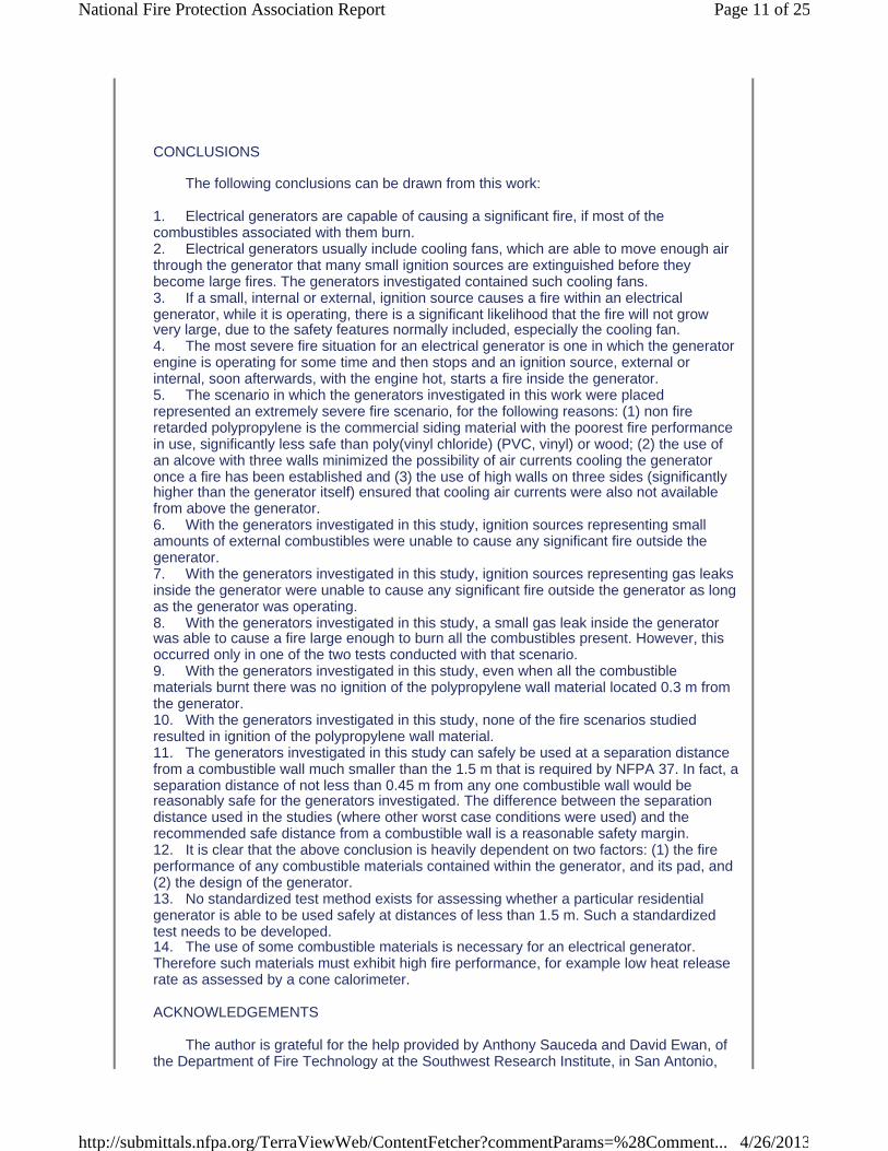
CONCLUSIONS
The following conclusions can be drawn from this work:
1. Electrical generators are capable of causing a significant fire, if most of the combustibles associated with them burn.2. Electrical generators usually include cooling fans, which are able to move enough air through the generator that many small ignition sources are extinguished before they become large fires. The generators investigated contained such cooling fans.3. If a small, internal or external, ignition source causes a fire within an electrical generator, while it is operating, there is a significant likelihood that the fire will not grow very large, due to the safety features normally included, especially the cooling fan. 4. The most severe fire situation for an electrical generator is one in which the generator engine is operating for some time and then stops and an ignition source, external or internal, soon afterwards, with the engine hot, starts a fire inside the generator.5. The scenario in which the generators investigated in this work were placed represented an extremely severe fire scenario, for the following reasons: (1) non fire retarded polypropylene is the commercial siding material with the poorest fire performance in use, significantly less safe than poly(vinyl chloride) (PVC, vinyl) or wood; (2) the use of an alcove with three walls minimized the possibility of air currents cooling the generator once a fire has been established and (3) the use of high walls on three sides (significantly higher than the generator itself) ensured that cooling air currents were also not available from above the generator.6. With the generators investigated in this study, ignition sources representing small amounts of external combustibles were unable to cause any significant fire outside the generator.7. With the generators investigated in this study, ignition sources representing gas leaks inside the generator were unable to cause any significant fire outside the generator as long as the generator was operating.8. With the generators investigated in this study, a small gas leak inside the generator was able to cause a fire large enough to burn all the combustibles present. However, this occurred only in one of the two tests conducted with that scenario.9. With the generators investigated in this study, even when all the combustible materials burnt there was no ignition of the polypropylene wall material located 0.3 m from the generator.10. With the generators investigated in this study, none of the fire scenarios studied resulted in ignition of the polypropylene wall material.11. The generators investigated in this study can safely be used at a separation distance from a combustible wall much smaller than the 1.5 m that is required by NFPA 37. In fact, a separation distance of not less than 0.45 m from any one combustible wall would be reasonably safe for the generators investigated. The difference between the separation distance used in the studies (where other worst case conditions were used) and the recommended safe distance from a combustible wall is a reasonable safety margin.12. It is clear that the above conclusion is heavily dependent on two factors: (1) the fire performance of any combustible materials contained within the generator, and its pad, and (2) the design of the generator.13. No standardized test method exists for assessing whether a particular residential generator is able to be used safely at distances of less than 1.5 m. Such a standardized test needs to be developed.14. The use of some combustible materials is necessary for an electrical generator. Therefore such materials must exhibit high fire performance, for example low heat release rate as assessed by a cone calorimeter.
ACKNOWLEDGEMENTS
The author is grateful for the help provided by Anthony Sauceda and David Ewan, of the Department of Fire Technology at the Southwest Research Institute, in San Antonio,
Page 11 of 25National Fire Protection Association Report
4/26/2013http://submittals.nfpa.org/TerraViewWeb/ContentFetcher?commentParams=%28Comment...
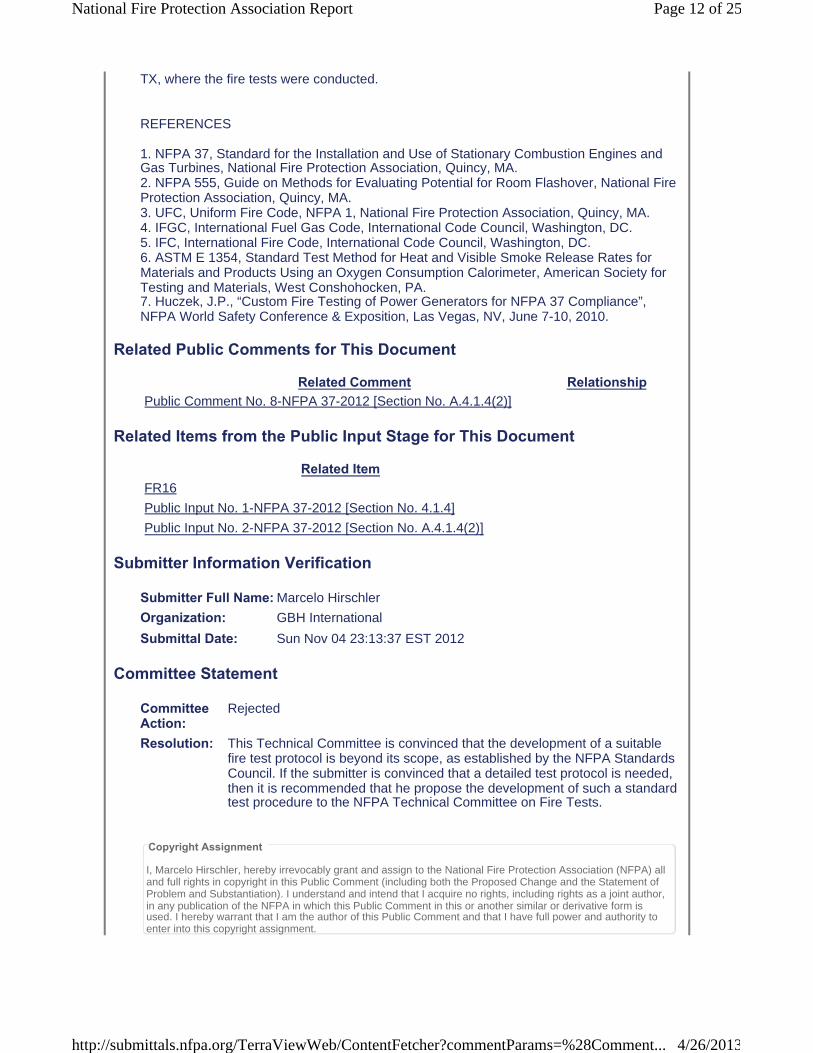
TX, where the fire tests were conducted.
REFERENCES
1. NFPA 37, Standard for the Installation and Use of Stationary Combustion Engines and Gas Turbines, National Fire Protection Association, Quincy, MA.2. NFPA 555, Guide on Methods for Evaluating Potential for Room Flashover, National Fire Protection Association, Quincy, MA.3. UFC, Uniform Fire Code, NFPA 1, National Fire Protection Association, Quincy, MA.4. IFGC, International Fuel Gas Code, International Code Council, Washington, DC.5. IFC, International Fire Code, International Code Council, Washington, DC.6. ASTM E 1354, Standard Test Method for Heat and Visible Smoke Release Rates for Materials and Products Using an Oxygen Consumption Calorimeter, American Society for Testing and Materials, West Conshohocken, PA.7. Huczek, J.P., “Custom Fire Testing of Power Generators for NFPA 37 Compliance”, NFPA World Safety Conference & Exposition, Las Vegas, NV, June 7-10, 2010.
Related Public Comments for This Document
Related Comment RelationshipPublic Comment No. 8-NFPA 37-2012 [Section No. A.4.1.4(2)]
Related Items from the Public Input Stage for This Document
Related ItemFR16
Public Input No. 1-NFPA 37-2012 [Section No. 4.1.4]
Public Input No. 2-NFPA 37-2012 [Section No. A.4.1.4(2)]
Submitter Information Verification
Submitter Full Name: Marcelo Hirschler
Organization: GBH International
Submittal Date: Sun Nov 04 23:13:37 EST 2012
Committee Statement
CommitteeAction:
Rejected
Resolution: This Technical Committee is convinced that the development of a suitable fire test protocol is beyond its scope, as established by the NFPA Standards Council. If the submitter is convinced that a detailed test protocol is needed, then it is recommended that he propose the development of such a standard test procedure to the NFPA Technical Committee on Fire Tests.
Copyright Assignment
I, Marcelo Hirschler, hereby irrevocably grant and assign to the National Fire Protection Association (NFPA) all and full rights in copyright in this Public Comment (including both the Proposed Change and the Statement of Problem and Substantiation). I understand and intend that I acquire no rights, including rights as a joint author, in any publication of the NFPA in which this Public Comment in this or another similar or derivative form is used. I hereby warrant that I am the author of this Public Comment and that I have full power and authority to enter into this copyright assignment.
Page 12 of 25National Fire Protection Association Report
4/26/2013http://submittals.nfpa.org/TerraViewWeb/ContentFetcher?commentParams=%28Comment...
By checking this box I affirm that I am Marcelo Hirschler, and I agree to be legally bound by the above Copyright Assignment and the terms and conditions contained therein. I understand and intend that, bychecking this box, I am creating an electronic signature that will, upon my submission of this form, have the same legal force and effect as a handwritten signature
Page 13 of 25National Fire Protection Association Report
4/26/2013http://submittals.nfpa.org/TerraViewWeb/ContentFetcher?commentParams=%28Comment...
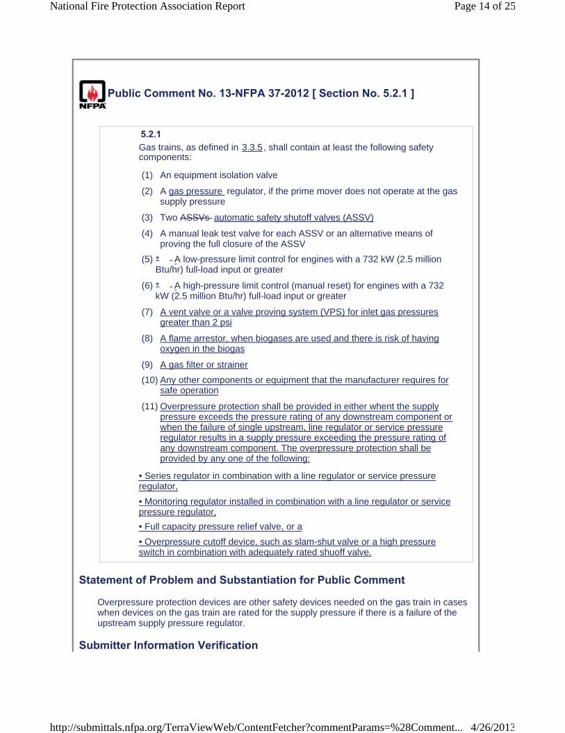
Public Comment No. 13-NFPA 37-2012 [ Section No. 5.2.1 ]
5.2.1 Gas trains, as defined in 3.3.5, shall contain at least the following safety components:
(1) An equipment isolation valve
(2) A gas pressure regulator, if the prime mover does not operate at the gas supply pressure
(3) Two ASSVs automatic safety shutoff valves (ASSV)
(4) A manual leak test valve for each ASSV or an alternative means of proving the full closure of the ASSV
(5)
(6)
(7) A vent valve or a valve proving system (VPS) for inlet gas pressures greater than 2 psi
(8) A flame arrestor, when biogases are used and there is risk of having oxygen in the biogas
(9) A gas filter or strainer
(10) Any other components or equipment that the manufacturer requires for safe operation
(11) Overpressure protection shall be provided in either whent the supply pressure exceeds the pressure rating of any downstream component or when the failure of single upstream, line regulator or service pressure regulator results in a supply pressure exceeding the pressure rating of any downstream component. The overpressure protection shall be provided by any one of the following:
• Series regulator in combination with a line regulator or service pressure regulator,
• Monitoring regulator installed in combination with a line regulator or service pressure regulator,
• Full capacity pressure relief valve, or a
• Overpressure cutoff device, such as slam-shut valve or a high pressure switch in combination with adequately rated shuoff valve.
Statement of Problem and Substantiation for Public Comment
Overpressure protection devices are other safety devices needed on the gas train in cases when devices on the gas train are rated for the supply pressure if there is a failure of the upstream supply pressure regulator.
Submitter Information Verification
* A low-pressure limit control for engines with a 732 kW (2.5 million Btu/hr) full-load input or greater
* A high-pressure limit control (manual reset) for engines with a 732 kW (2.5 million Btu/hr) full-load input or greater
Page 14 of 25National Fire Protection Association Report
4/26/2013http://submittals.nfpa.org/TerraViewWeb/ContentFetcher?commentParams=%28Comment...
Submitter Full Name: Kevin Carlisle
Organization: Karl Dungs, Inc.
Submittal Date: Tue Nov 13 08:48:01 EST 2012
Committee Statement
CommitteeAction:
Rejected
Resolution: While the action on this Public Comment is noted as "Reject", the text being offered will be included in NFPA 37 as an annex item to 5.2.1(10), which is 5.2.1(7) in the 2010 edition of NFPA 37. See Second Revision No.18.
Copyright Assignment
I, Kevin Carlisle, hereby irrevocably grant and assign to the National Fire Protection Association (NFPA) all and full rights in copyright in this Public Comment (including both the Proposed Change and the Statement of Problem and Substantiation). I understand and intend that I acquire no rights, including rights as a joint author, in any publication of the NFPA in which this Public Comment in this or another similar or derivative form is used. I hereby warrant that I am the author of this Public Comment and that I have full power and authority to enter into this copyright assignment.
By checking this box I affirm that I am Kevin Carlisle, and I agree to be legally bound by the above Copyright Assignment and the terms and conditions contained therein. I understand and intend that, by checking this box, I am creating an electronic signature that will, upon my submission of this form, have the same legal force and effect as a handwritten signature
Page 15 of 25National Fire Protection Association Report
4/26/2013http://submittals.nfpa.org/TerraViewWeb/ContentFetcher?commentParams=%28Comment...

Public Comment No. 12-NFPA 37-2012 [ Section No. 5.2.2 ]
5.2.2 For engines operating at more than a gauge pressure of 14 kPa (2 psi) inlet gas pressure to the equipment isolation valve , either
( a ) a vent valve shall be provided between the two ASSVs
. This
(b) at least one safety valve shall be fitted with a proof of closure switch, or
(c) a listed valve proving system (VPS) shall be installed to prove the two ASSVs upon each startup or after each shutdown.The vent valve shall fail open without an externally supplied source of power and shall dischargeoutdoors.
Statement of Problem and Substantiation for Public Comment
A proof of closure switch is a safety device that can proof the position of the safety shutoff valve to prove that it is has not failed to close.
Submitter Information Verification
Submitter Full Name: Kevin Carlisle
Organization: Karl Dungs, Inc.
Submittal Date: Tue Nov 13 08:42:13 EST 2012
Committee Statement
CommitteeAction:
Rejected but see related SR
Resolution: SR-16-NFPA 37-2013
Statement: The Technical Committee agrees with the objective of this Public Comment, namely that a proof of closure switch is a safety device that can proof the position of the safety shutoff valve to prove that it is has not failed to close. The Technical Committee has revised it to make it more easily understood. This Second Revision also addresses Committee Input No. 13.
Copyright Assignment
I, Kevin Carlisle, hereby irrevocably grant and assign to the National Fire Protection Association (NFPA) all and full rights in copyright in this Public Comment (including both the Proposed Change and the Statement of Problem and Substantiation). I understand and intend that I acquire no rights, including rights as a joint author, in any publication of the NFPA in which this Public Comment in this or another similar or derivative form is used. I hereby warrant that I am the author of this Public Comment and that I have full power and authority to enter into this copyright assignment.
Page 16 of 25National Fire Protection Association Report
4/26/2013http://submittals.nfpa.org/TerraViewWeb/ContentFetcher?commentParams=%28Comment...

By checking this box I affirm that I am Kevin Carlisle, and I agree to be legally bound by the above Copyright Assignment and the terms and conditions contained therein. I understand and intend that, by checking this box, I am creating an electronic signature that will, upon my submission of this form, have the same legal force and effect as a handwritten signature
Page 17 of 25National Fire Protection Association Report
4/26/2013http://submittals.nfpa.org/TerraViewWeb/ContentFetcher?commentParams=%28Comment...
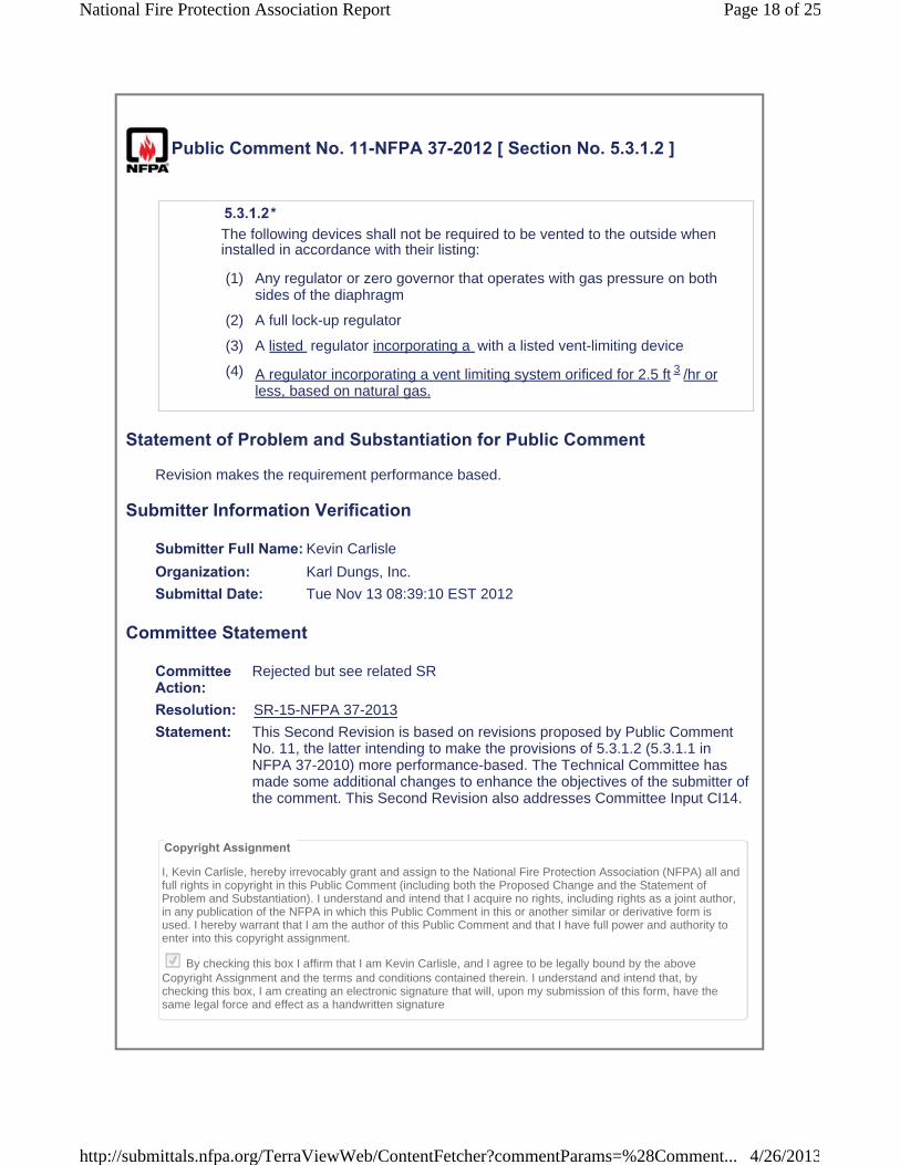
Public Comment No. 11-NFPA 37-2012 [ Section No. 5.3.1.2 ]
5.3.1.2*The following devices shall not be required to be vented to the outside when installed in accordance with their listing:
(1) Any regulator or zero governor that operates with gas pressure on both sides of the diaphragm
(2) A full lock-up regulator
(3) A listed regulator incorporating a with a listed vent-limiting device
(4) A regulator incorporating a vent limiting system orificed for 2.5 ft 3 /hr or less, based on natural gas.
Statement of Problem and Substantiation for Public Comment
Revision makes the requirement performance based.
Submitter Information Verification
Submitter Full Name: Kevin Carlisle
Organization: Karl Dungs, Inc.
Submittal Date: Tue Nov 13 08:39:10 EST 2012
Committee Statement
CommitteeAction:
Rejected but see related SR
Resolution: SR-15-NFPA 37-2013
Statement: This Second Revision is based on revisions proposed by Public Comment No. 11, the latter intending to make the provisions of 5.3.1.2 (5.3.1.1 in NFPA 37-2010) more performance-based. The Technical Committee has made some additional changes to enhance the objectives of the submitter of the comment. This Second Revision also addresses Committee Input CI14.
Copyright Assignment
I, Kevin Carlisle, hereby irrevocably grant and assign to the National Fire Protection Association (NFPA) all and full rights in copyright in this Public Comment (including both the Proposed Change and the Statement of Problem and Substantiation). I understand and intend that I acquire no rights, including rights as a joint author, in any publication of the NFPA in which this Public Comment in this or another similar or derivative form is used. I hereby warrant that I am the author of this Public Comment and that I have full power and authority to enter into this copyright assignment.
By checking this box I affirm that I am Kevin Carlisle, and I agree to be legally bound by the above Copyright Assignment and the terms and conditions contained therein. I understand and intend that, by checking this box, I am creating an electronic signature that will, upon my submission of this form, have the same legal force and effect as a handwritten signature
Page 18 of 25National Fire Protection Association Report
4/26/2013http://submittals.nfpa.org/TerraViewWeb/ContentFetcher?commentParams=%28Comment...
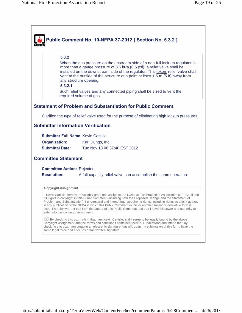
Public Comment No. 10-NFPA 37-2012 [ Section No. 5.3.2 ]
5.3.2 When the gas pressure on the upstream side of a non-full lock-up regulator is more than a gauge pressure of 3.5 kPa (0.5 psi), a relief valve shall be installed on the downstream side of the regulator. This token relief valve shall vent to the outside of the structure at a point at least 1.5 m (5 ft) away from any structure opening.5.3.2.1 Such relief valves and any connected piping shall be sized to vent the required volume of gas.
Statement of Problem and Substantiation for Public Comment
Clarified the type of relief valve used for the purpose of eliminating high lockup pressures.
Submitter Information Verification
Submitter Full Name: Kevin Carlisle
Organization: Karl Dungs, Inc.
Submittal Date: Tue Nov 13 08:37:40 EST 2012
Committee Statement
Committee Action: Rejected
Resolution: A full-capacity relief valve can accomplish the same operation.
Copyright Assignment
I, Kevin Carlisle, hereby irrevocably grant and assign to the National Fire Protection Association (NFPA) all and full rights in copyright in this Public Comment (including both the Proposed Change and the Statement ofProblem and Substantiation). I understand and intend that I acquire no rights, including rights as a joint author, in any publication of the NFPA in which this Public Comment in this or another similar or derivative form is used. I hereby warrant that I am the author of this Public Comment and that I have full power and authority to enter into this copyright assignment.
By checking this box I affirm that I am Kevin Carlisle, and I agree to be legally bound by the above Copyright Assignment and the terms and conditions contained therein. I understand and intend that, by checking this box, I am creating an electronic signature that will, upon my submission of this form, have the same legal force and effect as a handwritten signature
Page 19 of 25National Fire Protection Association Report
4/26/2013http://submittals.nfpa.org/TerraViewWeb/ContentFetcher?commentParams=%28Comment...
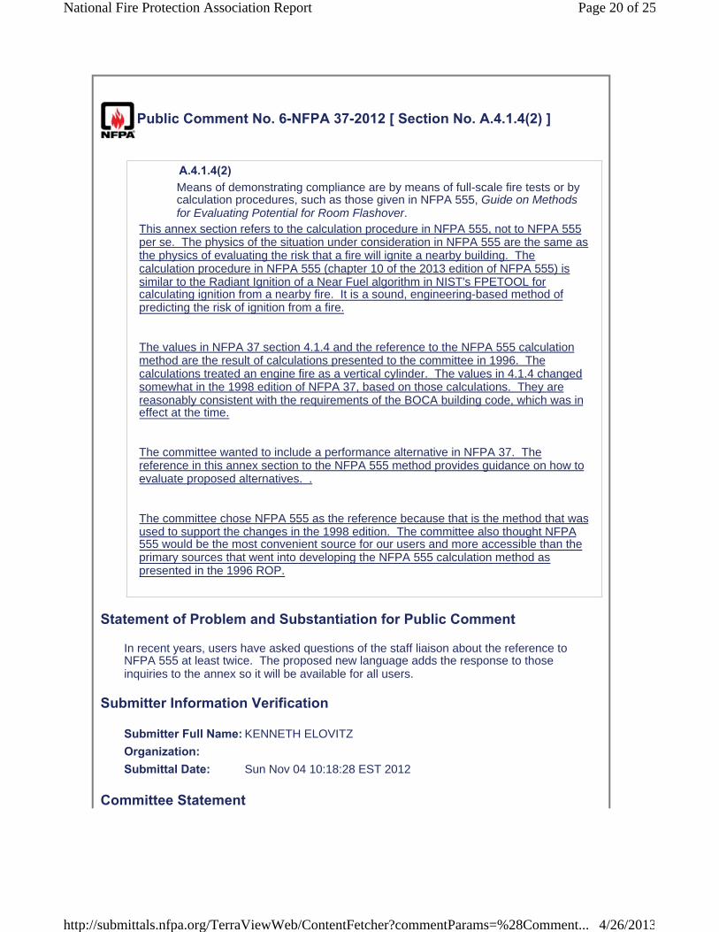
Public Comment No. 6-NFPA 37-2012 [ Section No. A.4.1.4(2) ]
A.4.1.4(2) Means of demonstrating compliance are by means of full-scale fire tests or by calculation procedures, such as those given in NFPA 555, Guide on Methods for Evaluating Potential for Room Flashover.
This annex section refers to the calculation procedure in NFPA 555, not to NFPA 555 per se. The physics of the situation under consideration in NFPA 555 are the same as the physics of evaluating the risk that a fire will ignite a nearby building. The calculation procedure in NFPA 555 (chapter 10 of the 2013 edition of NFPA 555) is similar to the Radiant Ignition of a Near Fuel algorithm in NIST's FPETOOL for calculating ignition from a nearby fire. It is a sound, engineering-based method of predicting the risk of ignition from a fire.
The values in NFPA 37 section 4.1.4 and the reference to the NFPA 555 calculation method are the result of calculations presented to the committee in 1996. The calculations treated an engine fire as a vertical cylinder. The values in 4.1.4 changed somewhat in the 1998 edition of NFPA 37, based on those calculations. They are reasonably consistent with the requirements of the BOCA building code, which was in effect at the time.
The committee wanted to include a performance alternative in NFPA 37. The reference in this annex section to the NFPA 555 method provides guidance on how to evaluate proposed alternatives. .
The committee chose NFPA 555 as the reference because that is the method that was used to support the changes in the 1998 edition. The committee also thought NFPA 555 would be the most convenient source for our users and more accessible than the primary sources that went into developing the NFPA 555 calculation method as presented in the 1996 ROP.
Statement of Problem and Substantiation for Public Comment
In recent years, users have asked questions of the staff liaison about the reference to NFPA 555 at least twice. The proposed new language adds the response to those inquiries to the annex so it will be available for all users.
Submitter Information Verification
Submitter Full Name: KENNETH ELOVITZ
Organization: Submittal Date: Sun Nov 04 10:18:28 EST 2012
Committee Statement
Page 20 of 25National Fire Protection Association Report
4/26/2013http://submittals.nfpa.org/TerraViewWeb/ContentFetcher?commentParams=%28Comment...
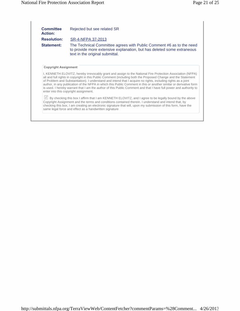
Committee Action:
Rejected but see related SR
Resolution: SR-4-NFPA 37-2013
Statement: The Technical Committee agrees with Public Comment #6 as to the need to provide more extensive explanation, but has deleted some extraneous text in the original submittal.
Copyright Assignment
I, KENNETH ELOVITZ, hereby irrevocably grant and assign to the National Fire Protection Association (NFPA)all and full rights in copyright in this Public Comment (including both the Proposed Change and the Statement of Problem and Substantiation). I understand and intend that I acquire no rights, including rights as a joint author, in any publication of the NFPA in which this Public Comment in this or another similar or derivative form is used. I hereby warrant that I am the author of this Public Comment and that I have full power and authority to enter into this copyright assignment.
By checking this box I affirm that I am KENNETH ELOVITZ, and I agree to be legally bound by the above Copyright Assignment and the terms and conditions contained therein. I understand and intend that, by checking this box, I am creating an electronic signature that will, upon my submission of this form, have the same legal force and effect as a handwritten signature
Page 21 of 25National Fire Protection Association Report
4/26/2013http://submittals.nfpa.org/TerraViewWeb/ContentFetcher?commentParams=%28Comment...

Public Comment No. 8-NFPA 37-2012 [ Section No. A.4.1.4(2) ]
A.4.1.4(2) Means of demonstrating compliance are by means of full-scale fire tests or by calculation Calculation procedures, such as those given in NFPA 555, Guide on Methods for Evaluating Potential for Room Flashover, are useful tools to assess the probability of safe engine placement .
Statement of Problem and Substantiation for Public Comment
This is tied to the proposed change to 4.1.4, and the criteria for the test method are proposed to be shown in the body of the standard.
Related Public Comments for This Document
Related Comment RelationshipPublic Comment No. 7-NFPA 37-2012 [Section No. 4.1.4]
Related Items from the Public Input Stage for This Document
Related ItemPublic Input No. 2-NFPA 37-2012 [Section No. A.4.1.4(2)]
Submitter Information Verification
Submitter Full Name: Marcelo Hirschler
Organization: GBH International
Submittal Date: Sun Nov 04 23:30:27 EST 2012
Committee Statement
CommitteeAction:
Rejected
Resolution: Since Public Comment No. 7 was not accepted, this comment is not appropriate, since it depends on the acceptance of the former comment.
Copyright Assignment
I, Marcelo Hirschler, hereby irrevocably grant and assign to the National Fire Protection Association (NFPA) all and full rights in copyright in this Public Comment (including both the Proposed Change and the Statement of Problem and Substantiation). I understand and intend that I acquire no rights, including rights as a joint author, in any publication of the NFPA in which this Public Comment in this or another similar or derivative form is used. I hereby warrant that I am the author of this Public Comment and that I have full power and authority to enter into this copyright assignment.
By checking this box I affirm that I am Marcelo Hirschler, and I agree to be legally bound by the above Copyright Assignment and the terms and conditions contained therein. I understand and intend that, by checking this box, I am creating an electronic signature that will, upon my submission of this form, have the same legal force and effect as a handwritten signature
Page 22 of 25National Fire Protection Association Report
4/26/2013http://submittals.nfpa.org/TerraViewWeb/ContentFetcher?commentParams=%28Comment...
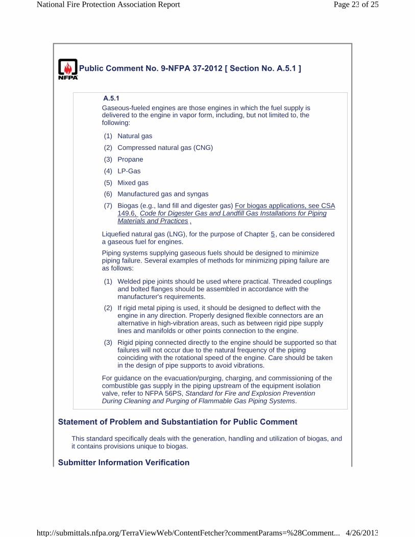
Public Comment No. 9-NFPA 37-2012 [ Section No. A.5.1 ]
A.5.1 Gaseous-fueled engines are those engines in which the fuel supply is delivered to the engine in vapor form, including, but not limited to, the following:
(1) Natural gas
(2) Compressed natural gas (CNG)
(3) Propane
(4) LP-Gas
(5) Mixed gas
(6) Manufactured gas and syngas
(7) Biogas (e.g., land fill and digester gas) For biogas applications, see CSA149.6, Code for Digester Gas and Landfill Gas Installations for Piping Materials and Practices .
Liquefied natural gas (LNG), for the purpose of Chapter 5, can be considered a gaseous fuel for engines.
Piping systems supplying gaseous fuels should be designed to minimize piping failure. Several examples of methods for minimizing piping failure are as follows:
(1) Welded pipe joints should be used where practical. Threaded couplings and bolted flanges should be assembled in accordance with the manufacturer's requirements.
(2) If rigid metal piping is used, it should be designed to deflect with the engine in any direction. Properly designed flexible connectors are an alternative in high-vibration areas, such as between rigid pipe supply lines and manifolds or other points connection to the engine.
(3) Rigid piping connected directly to the engine should be supported so that failures will not occur due to the natural frequency of the piping coinciding with the rotational speed of the engine. Care should be taken in the design of pipe supports to avoid vibrations.
For guidance on the evacuation/purging, charging, and commissioning of the combustible gas supply in the piping upstream of the equipment isolation valve, refer to NFPA 56PS, Standard for Fire and Explosion Prevention During Cleaning and Purging of Flammable Gas Piping Systems.
Statement of Problem and Substantiation for Public Comment
This standard specifically deals with the generation, handling and utilization of biogas, and it contains provisions unique to biogas.
Submitter Information Verification
Page 23 of 25National Fire Protection Association Report
4/26/2013http://submittals.nfpa.org/TerraViewWeb/ContentFetcher?commentParams=%28Comment...
Submitter Full Name: Kevin Carlisle
Organization: Karl Dungs, Inc.
Submittal Date: Tue Nov 13 08:34:58 EST 2012
Committee Statement
CommitteeAction:
Accepted
Resolution: SR-5-NFPA 37-2013
Statement: This standard specifically deals with the generation, handling and utilization of biogas, and it contains provisions unique to biogas.
Copyright Assignment
I, Kevin Carlisle, hereby irrevocably grant and assign to the National Fire Protection Association (NFPA) all and full rights in copyright in this Public Comment (including both the Proposed Change and the Statement ofProblem and Substantiation). I understand and intend that I acquire no rights, including rights as a joint author, in any publication of the NFPA in which this Public Comment in this or another similar or derivative form is used. I hereby warrant that I am the author of this Public Comment and that I have full power and authority to enter into this copyright assignment.
By checking this box I affirm that I am Kevin Carlisle, and I agree to be legally bound by the above Copyright Assignment and the terms and conditions contained therein. I understand and intend that, by checking this box, I am creating an electronic signature that will, upon my submission of this form, have the same legal force and effect as a handwritten signature
Page 24 of 25National Fire Protection Association Report
4/26/2013http://submittals.nfpa.org/TerraViewWeb/ContentFetcher?commentParams=%28Comment...

Public Comment No. 3-NFPA 37-2012 [ New Section after A.9.3.1 ]
TITLE OF NEW CONTENTA.9.3.2 {Please provide clarification as to how 9.3.2(4) does not contradict 9.3.1.1}
Statement of Problem and Substantiation for Public Comment
I have not provided a proposed change, rather, I am requesting clarification in Appendix A.9.3.2 . Specifically, how does 9.3.2(4) coexist with the exception granted in 9.3.1.1 regarding a unit trip due to loss of flame?
Submitter Information Verification
Submitter Full Name: MICHAEL KRUGER
Organization: EXELON POWER
Submittal Date: Mon Sep 24 10:44:15 EDT 2012
Committee Statement
CommitteeAction:
Rejected but see related SR
Resolution: SR-14-NFPA 37-2013
Statement: Public Comment #3 reads as follows: "I have not provided a proposed change, rather, I am requesting clarification in Appendix A.9.3.2 . Specifically, how does 9.3.2(4) coexist with the exception granted in 9.3.1.1 regarding a unit trip due to loss of flame?" This Second Revision is a consequence of Public Comment #3, which pointed out an inconsistency between 9.3.1, which addresses an emergency situation, and 9.3.2, which addresses safety of the engine. See also Second Revision 13 for the amended version of 9.3.2(4).
Copyright Assignment
I, MICHAEL KRUGER, hereby irrevocably grant and assign to the National Fire Protection Association (NFPA)all and full rights in copyright in this Public Comment (including both the Proposed Change and the Statement of Problem and Substantiation). I understand and intend that I acquire no rights, including rights as a joint author, in any publication of the NFPA in which this Public Comment in this or another similar or derivative form is used. I hereby warrant that I am the author of this Public Comment and that I have full power and authority to enter into this copyright assignment.
By checking this box I affirm that I am MICHAEL KRUGER, and I agree to be legally bound by the above Copyright Assignment and the terms and conditions contained therein. I understand and intend that, by checking this box, I am creating an electronic signature that will, upon my submission of this form, have the same legal force and effect as a handwritten signature
Page 25 of 25National Fire Protection Association Report
4/26/2013http://submittals.nfpa.org/TerraViewWeb/ContentFetcher?commentParams=%28Comment...
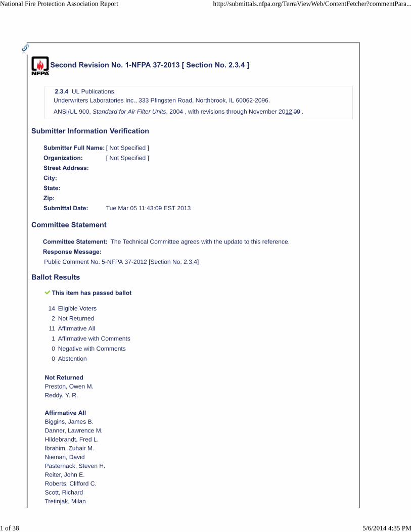
Second Revision No. 1-NFPA 37-2013 [ Section No. 2.3.4 ]
2.3.4 UL Publications.
Underwriters Laboratories Inc., 333 Pfingsten Road, Northbrook, IL 60062-2096.
ANSI/UL 900, Standard for Air Filter Units, 2004 , with revisions through November 2012 09 .
Submitter Information Verification
Submitter Full Name: [ Not Specified ]
Organization: [ Not Specified ]
Street Address:City:State:Zip:Submittal Date: Tue Mar 05 11:43:09 EST 2013
Committee Statement
Committee Statement: The Technical Committee agrees with the update to this reference.
Response Message:Public Comment No. 5-NFPA 37-2012 [Section No. 2.3.4]
Ballot Results
This item has passed ballot
14 Eligible Voters
2 Not Returned
11 Affirmative All
1 Affirmative with Comments
0 Negative with Comments
0 Abstention
Not ReturnedPreston, Owen M.
Reddy, Y. R.
Affirmative AllBiggins, James B.
Danner, Lawrence M.
Hildebrandt, Fred L.
Ibrahim, Zuhair M.
Nieman, David
Pasternack, Steven H.
Reiter, John E.
Roberts, Clifford C.
Scott, Richard
Tretinjak, Milan
National Fire Protection Association Report http://submittals.nfpa.org/TerraViewWeb/ContentFetcher?commentPara...
1 of 38 5/6/2014 4:35 PM

Wertz, Bruce J.
Affirmative with CommentElovitz, Kenneth M.
I think it is important to note that this change is not merely an update. There was a major substantive change toUL 900 that eliminates the Class 1/Class 2 filter distinctions in UL 900. That change affects NFPA 37 and wasaddressed in the changes to 4.1.1.5 accepted in the first revision.
National Fire Protection Association Report http://submittals.nfpa.org/TerraViewWeb/ContentFetcher?commentPara...
2 of 38 5/6/2014 4:35 PM
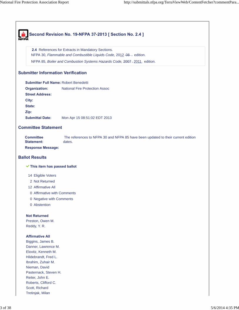
Second Revision No. 19-NFPA 37-2013 [ Section No. 2.4 ]
2.4 References for Extracts in Mandatory Sections.
NFPA 30, Flammable and Combustible Liquids Code, 2012 08 . edition.
NFPA 85, Boiler and Combustion Systems Hazards Code, 2007 . 2011. edition.
Submitter Information Verification
Submitter Full Name: Robert Benedetti
Organization: National Fire Protection Assoc
Street Address:City:State:Zip:Submittal Date: Mon Apr 15 08:51:02 EDT 2013
Committee Statement
CommitteeStatement:
The references to NFPA 30 and NFPA 85 have been updated to their current editiondates.
Response Message:
Ballot Results
This item has passed ballot
14 Eligible Voters
2 Not Returned
12 Affirmative All
0 Affirmative with Comments
0 Negative with Comments
0 Abstention
Not ReturnedPreston, Owen M.
Reddy, Y. R.
Affirmative AllBiggins, James B.
Danner, Lawrence M.
Elovitz, Kenneth M.
Hildebrandt, Fred L.
Ibrahim, Zuhair M.
Nieman, David
Pasternack, Steven H.
Reiter, John E.
Roberts, Clifford C.
Scott, Richard
Tretinjak, Milan
National Fire Protection Association Report http://submittals.nfpa.org/TerraViewWeb/ContentFetcher?commentPara...
3 of 38 5/6/2014 4:35 PM

Wertz, Bruce J.
National Fire Protection Association Report http://submittals.nfpa.org/TerraViewWeb/ContentFetcher?commentPara...
4 of 38 5/6/2014 4:35 PM
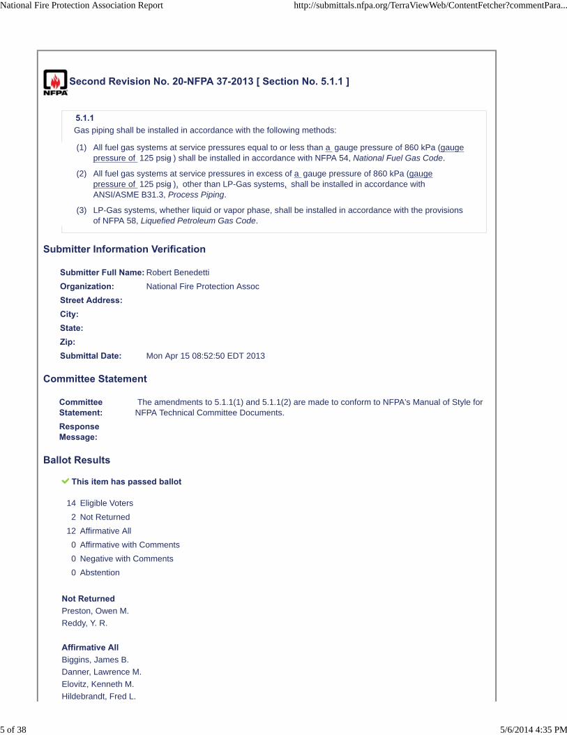
Second Revision No. 20-NFPA 37-2013 [ Section No. 5.1.1 ]
5.1.1
Gas piping shall be installed in accordance with the following methods:
(1) All fuel gas systems at service pressures equal to or less than a gauge pressure of 860 kPa (gaugepressure of 125 psig ) shall be installed in accordance with NFPA 54, National Fuel Gas Code.
(2) All fuel gas systems at service pressures in excess of a gauge pressure of 860 kPa (gaugepressure of 125 psig ), other than LP-Gas systems, shall be installed in accordance withANSI/ASME B31.3, Process Piping.
(3) LP-Gas systems, whether liquid or vapor phase, shall be installed in accordance with the provisionsof NFPA 58, Liquefied Petroleum Gas Code.
Submitter Information Verification
Submitter Full Name: Robert Benedetti
Organization: National Fire Protection Assoc
Street Address:City:State:Zip:Submittal Date: Mon Apr 15 08:52:50 EDT 2013
Committee Statement
CommitteeStatement:
The amendments to 5.1.1(1) and 5.1.1(2) are made to conform to NFPA's Manual of Style forNFPA Technical Committee Documents.
ResponseMessage:
Ballot Results
This item has passed ballot
14 Eligible Voters
2 Not Returned
12 Affirmative All
0 Affirmative with Comments
0 Negative with Comments
0 Abstention
Not ReturnedPreston, Owen M.
Reddy, Y. R.
Affirmative AllBiggins, James B.
Danner, Lawrence M.
Elovitz, Kenneth M.
Hildebrandt, Fred L.
National Fire Protection Association Report http://submittals.nfpa.org/TerraViewWeb/ContentFetcher?commentPara...
5 of 38 5/6/2014 4:35 PM

Ibrahim, Zuhair M.
Nieman, David
Pasternack, Steven H.
Reiter, John E.
Roberts, Clifford C.
Scott, Richard
Tretinjak, Milan
Wertz, Bruce J.
National Fire Protection Association Report http://submittals.nfpa.org/TerraViewWeb/ContentFetcher?commentPara...
6 of 38 5/6/2014 4:35 PM
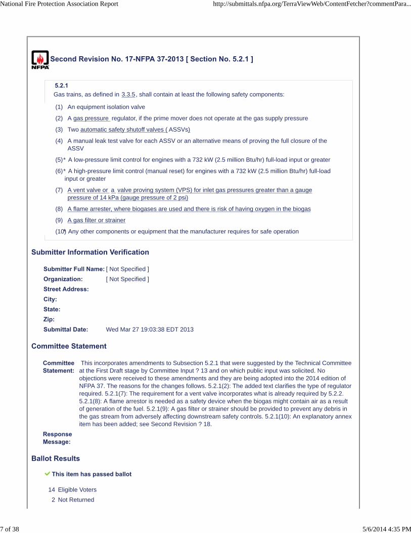
Second Revision No. 17-NFPA 37-2013 [ Section No. 5.2.1 ]
5.2.1
Gas trains, as defined in 3.3.5, shall contain at least the following safety components:
(1) An equipment isolation valve
(2) A gas pressure regulator, if the prime mover does not operate at the gas supply pressure
(3) Two automatic safety shutoff valves ( ASSVs)
(4) A manual leak test valve for each ASSV or an alternative means of proving the full closure of theASSV
(5)
(6)
(7) A vent valve or a valve proving system (VPS) for inlet gas pressures greater than a gaugepressure of 14 kPa (gauge pressure of 2 psi)
(8) A flame arrester, where biogases are used and there is risk of having oxygen in the biogas
(9) A gas filter or strainer
(10)
Submitter Information Verification
Submitter Full Name: [ Not Specified ]
Organization: [ Not Specified ]
Street Address:City:State:Zip:Submittal Date: Wed Mar 27 19:03:38 EDT 2013
Committee Statement
CommitteeStatement:
This incorporates amendments to Subsection 5.2.1 that were suggested by the Technical Committeeat the First Draft stage by Committee Input ? 13 and on which public input was solicited. Noobjections were received to these amendments and they are being adopted into the 2014 edition ofNFPA 37. The reasons for the changes follows. 5.2.1(2): The added text clarifies the type of regulatorrequired. 5.2.1(7): The requirement for a vent valve incorporates what is already required by 5.2.2.5.2.1(8): A flame arrestor is needed as a safety device when the biogas might contain air as a resultof generation of the fuel. 5.2.1(9): A gas filter or strainer should be provided to prevent any debris inthe gas stream from adversely affecting downstream safety controls. 5.2.1(10): An explanatory annexitem has been added; see Second Revision ? 18.
ResponseMessage:
Ballot Results
This item has passed ballot
14 Eligible Voters
2 Not Returned
* A low-pressure limit control for engines with a 732 kW (2.5 million Btu/hr) full-load input or greater
* A high-pressure limit control (manual reset) for engines with a 732 kW (2.5 million Btu/hr) full-loadinput or greater
* Any other components or equipment that the manufacturer requires for safe operation
National Fire Protection Association Report http://submittals.nfpa.org/TerraViewWeb/ContentFetcher?commentPara...
7 of 38 5/6/2014 4:35 PM
12 Affirmative All
0 Affirmative with Comments
0 Negative with Comments
0 Abstention
Not ReturnedPreston, Owen M.
Reddy, Y. R.
Affirmative AllBiggins, James B.
Danner, Lawrence M.
Elovitz, Kenneth M.
Hildebrandt, Fred L.
Ibrahim, Zuhair M.
Nieman, David
Pasternack, Steven H.
Reiter, John E.
Roberts, Clifford C.
Scott, Richard
Tretinjak, Milan
Wertz, Bruce J.
National Fire Protection Association Report http://submittals.nfpa.org/TerraViewWeb/ContentFetcher?commentPara...
8 of 38 5/6/2014 4:35 PM
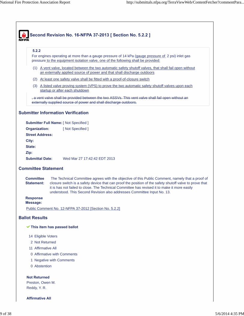
Second Revision No. 16-NFPA 37-2013 [ Section No. 5.2.2 ]
5.2.2
For engines operating at more than a gauge pressure of 14 kPa (gauge pressure of 2 psi) inlet gaspressure to the equipment isolation valve, one of the following shall be provided:
(1) A vent valve, located between the two automatic safety shutoff valves, that shall fail open withoutan externally applied source of power and that shall discharge outdoors
(2) At least one safety valve shall be fitted with a proof-of-closure switch
(3) A listed valve proving system (VPS) to prove the two automatic safety shutoff valves upon eachstartup or after each shutdown
, a vent valve shall be provided between the two ASSVs. This vent valve shall fail open without anexternally supplied source of power and shall discharge outdoors.
Submitter Information Verification
Submitter Full Name: [ Not Specified ]
Organization: [ Not Specified ]
Street Address:City:State:Zip:Submittal Date: Wed Mar 27 17:42:42 EDT 2013
Committee Statement
CommitteeStatement:
The Technical Committee agrees with the objective of this Public Comment, namely that a proof ofclosure switch is a safety device that can proof the position of the safety shutoff valve to prove thatit is has not failed to close. The Technical Committee has revised it to make it more easilyunderstood. This Second Revision also addresses Committee Input No. 13.
ResponseMessage:Public Comment No. 12-NFPA 37-2012 [Section No. 5.2.2]
Ballot Results
This item has passed ballot
14 Eligible Voters
2 Not Returned
11 Affirmative All
0 Affirmative with Comments
1 Negative with Comments
0 Abstention
Not ReturnedPreston, Owen M.
Reddy, Y. R.
Affirmative All
National Fire Protection Association Report http://submittals.nfpa.org/TerraViewWeb/ContentFetcher?commentPara...
9 of 38 5/6/2014 4:35 PM
Biggins, James B.
Danner, Lawrence M.
Hildebrandt, Fred L.
Ibrahim, Zuhair M.
Nieman, David
Pasternack, Steven H.
Reiter, John E.
Roberts, Clifford C.
Scott, Richard
Tretinjak, Milan
Wertz, Bruce J.
Negative with CommentElovitz, Kenneth M.
I question whether this requirement is a necessary addition to NFPA 37. It does not exist in the gas trainrequirements for boilers (UL, FM, IRI) that were the basis for adding this information to NFPA 37. No one hasidentified any fire safety consideration related to fuel handling that differentiates engines from boilers and warrantsadditional requirements in NFPA 37.
National Fire Protection Association Report http://submittals.nfpa.org/TerraViewWeb/ContentFetcher?commentPara...
10 of 38 5/6/2014 4:35 PM
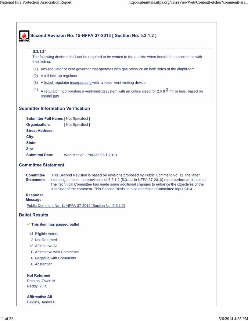
Second Revision No. 15-NFPA 37-2013 [ Section No. 5.3.1.2 ]
5.3.1.2*
The following devices shall not be required to be vented to the outside when installed in accordance withtheir listing:
(1) Any regulator or zero governor that operates with gas pressure on both sides of the diaphragm
(2) A full lock-up regulator
(3) A listed regulator incorporating with a listed vent-limiting device
(4) A regulator incorporating a vent-limiting system with an orifice sized for 2.5 ft 3 /hr or less, based onnatural gas
Submitter Information Verification
Submitter Full Name: [ Not Specified ]
Organization: [ Not Specified ]
Street Address:City:State:Zip:Submittal Date: Wed Mar 27 17:00:32 EDT 2013
Committee Statement
CommitteeStatement:
This Second Revision is based on revisions proposed by Public Comment No. 11, the latterintending to make the provisions of 5.3.1.2 (5.3.1.1 in NFPA 37-2010) more performance-based.The Technical Committee has made some additional changes to enhance the objectives of thesubmitter of the comment. This Second Revision also addresses Committee Input CI14.
ResponseMessage:Public Comment No. 11-NFPA 37-2012 [Section No. 5.3.1.2]
Ballot Results
This item has passed ballot
14 Eligible Voters
2 Not Returned
12 Affirmative All
0 Affirmative with Comments
0 Negative with Comments
0 Abstention
Not ReturnedPreston, Owen M.
Reddy, Y. R.
Affirmative AllBiggins, James B.
National Fire Protection Association Report http://submittals.nfpa.org/TerraViewWeb/ContentFetcher?commentPara...
11 of 38 5/6/2014 4:35 PM
Danner, Lawrence M.
Elovitz, Kenneth M.
Hildebrandt, Fred L.
Ibrahim, Zuhair M.
Nieman, David
Pasternack, Steven H.
Reiter, John E.
Roberts, Clifford C.
Scott, Richard
Tretinjak, Milan
Wertz, Bruce J.
National Fire Protection Association Report http://submittals.nfpa.org/TerraViewWeb/ContentFetcher?commentPara...
12 of 38 5/6/2014 4:35 PM
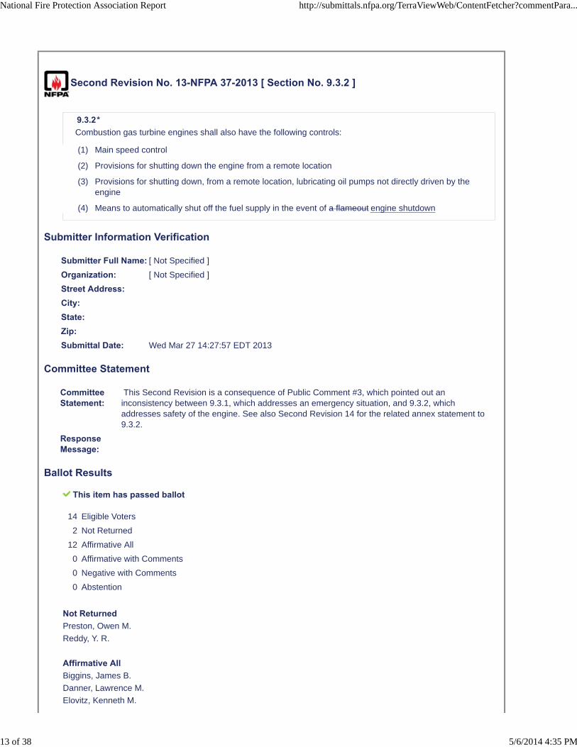
Second Revision No. 13-NFPA 37-2013 [ Section No. 9.3.2 ]
9.3.2*
Combustion gas turbine engines shall also have the following controls:
(1) Main speed control
(2) Provisions for shutting down the engine from a remote location
(3) Provisions for shutting down, from a remote location, lubricating oil pumps not directly driven by theengine
(4) Means to automatically shut off the fuel supply in the event of a flameout engine shutdown
Submitter Information Verification
Submitter Full Name: [ Not Specified ]
Organization: [ Not Specified ]
Street Address:City:State:Zip:Submittal Date: Wed Mar 27 14:27:57 EDT 2013
Committee Statement
CommitteeStatement:
This Second Revision is a consequence of Public Comment #3, which pointed out aninconsistency between 9.3.1, which addresses an emergency situation, and 9.3.2, whichaddresses safety of the engine. See also Second Revision 14 for the related annex statement to9.3.2.
ResponseMessage:
Ballot Results
This item has passed ballot
14 Eligible Voters
2 Not Returned
12 Affirmative All
0 Affirmative with Comments
0 Negative with Comments
0 Abstention
Not ReturnedPreston, Owen M.
Reddy, Y. R.
Affirmative AllBiggins, James B.
Danner, Lawrence M.
Elovitz, Kenneth M.
National Fire Protection Association Report http://submittals.nfpa.org/TerraViewWeb/ContentFetcher?commentPara...
13 of 38 5/6/2014 4:35 PM

Hildebrandt, Fred L.
Ibrahim, Zuhair M.
Nieman, David
Pasternack, Steven H.
Reiter, John E.
Roberts, Clifford C.
Scott, Richard
Tretinjak, Milan
Wertz, Bruce J.
National Fire Protection Association Report http://submittals.nfpa.org/TerraViewWeb/ContentFetcher?commentPara...
14 of 38 5/6/2014 4:35 PM
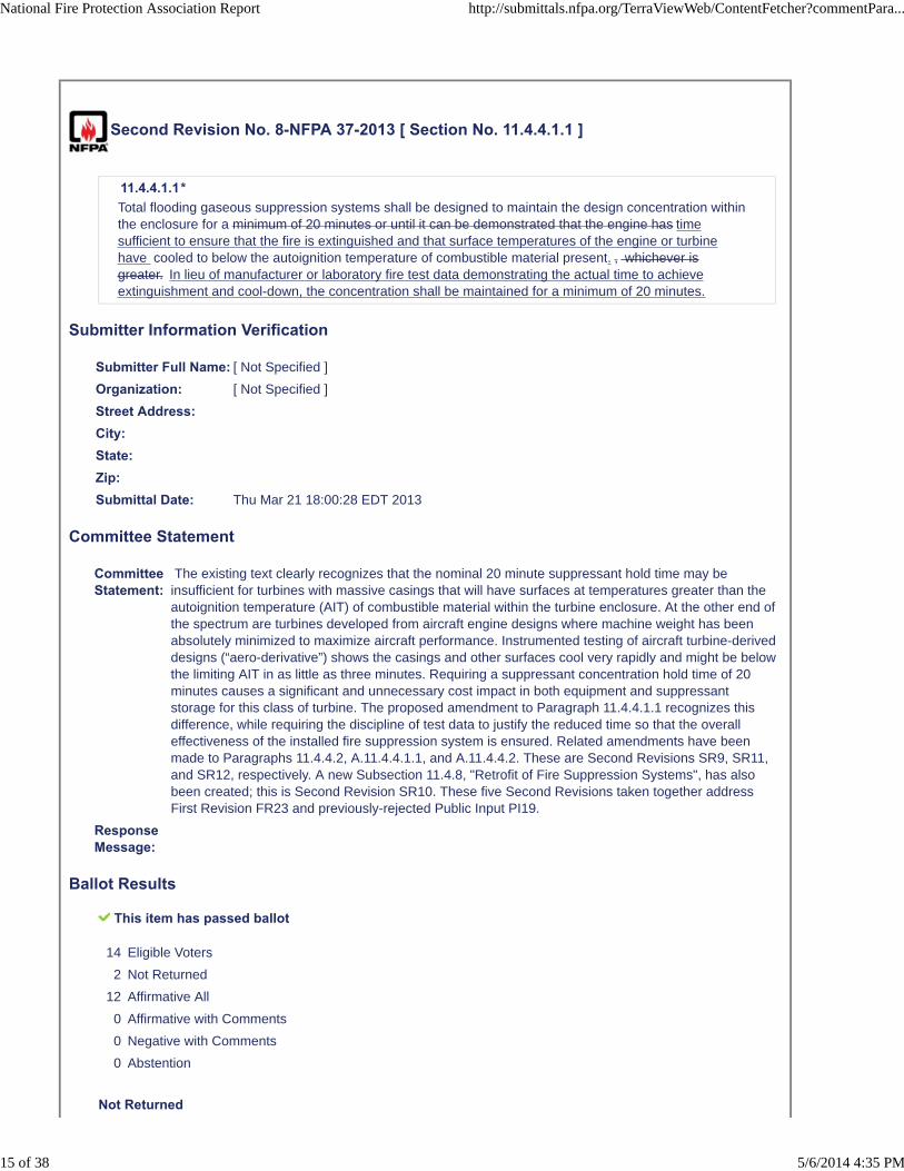
Second Revision No. 8-NFPA 37-2013 [ Section No. 11.4.4.1.1 ]
11.4.4.1.1*
Total flooding gaseous suppression systems shall be designed to maintain the design concentration withinthe enclosure for a minimum of 20 minutes or until it can be demonstrated that the engine has timesufficient to ensure that the fire is extinguished and that surface temperatures of the engine or turbinehave cooled to below the autoignition temperature of combustible material present. , whichever isgreater. In lieu of manufacturer or laboratory fire test data demonstrating the actual time to achieveextinguishment and cool-down, the concentration shall be maintained for a minimum of 20 minutes.
Submitter Information Verification
Submitter Full Name: [ Not Specified ]
Organization: [ Not Specified ]
Street Address:City:State:Zip:Submittal Date: Thu Mar 21 18:00:28 EDT 2013
Committee Statement
CommitteeStatement:
The existing text clearly recognizes that the nominal 20 minute suppressant hold time may beinsufficient for turbines with massive casings that will have surfaces at temperatures greater than theautoignition temperature (AIT) of combustible material within the turbine enclosure. At the other end ofthe spectrum are turbines developed from aircraft engine designs where machine weight has beenabsolutely minimized to maximize aircraft performance. Instrumented testing of aircraft turbine-deriveddesigns (“aero-derivative”) shows the casings and other surfaces cool very rapidly and might be belowthe limiting AIT in as little as three minutes. Requiring a suppressant concentration hold time of 20minutes causes a significant and unnecessary cost impact in both equipment and suppressantstorage for this class of turbine. The proposed amendment to Paragraph 11.4.4.1.1 recognizes thisdifference, while requiring the discipline of test data to justify the reduced time so that the overalleffectiveness of the installed fire suppression system is ensured. Related amendments have beenmade to Paragraphs 11.4.4.2, A.11.4.4.1.1, and A.11.4.4.2. These are Second Revisions SR9, SR11,and SR12, respectively. A new Subsection 11.4.8, "Retrofit of Fire Suppression Systems", has alsobeen created; this is Second Revision SR10. These five Second Revisions taken together addressFirst Revision FR23 and previously-rejected Public Input PI19.
ResponseMessage:
Ballot Results
This item has passed ballot
14 Eligible Voters
2 Not Returned
12 Affirmative All
0 Affirmative with Comments
0 Negative with Comments
0 Abstention
Not Returned
National Fire Protection Association Report http://submittals.nfpa.org/TerraViewWeb/ContentFetcher?commentPara...
15 of 38 5/6/2014 4:35 PM
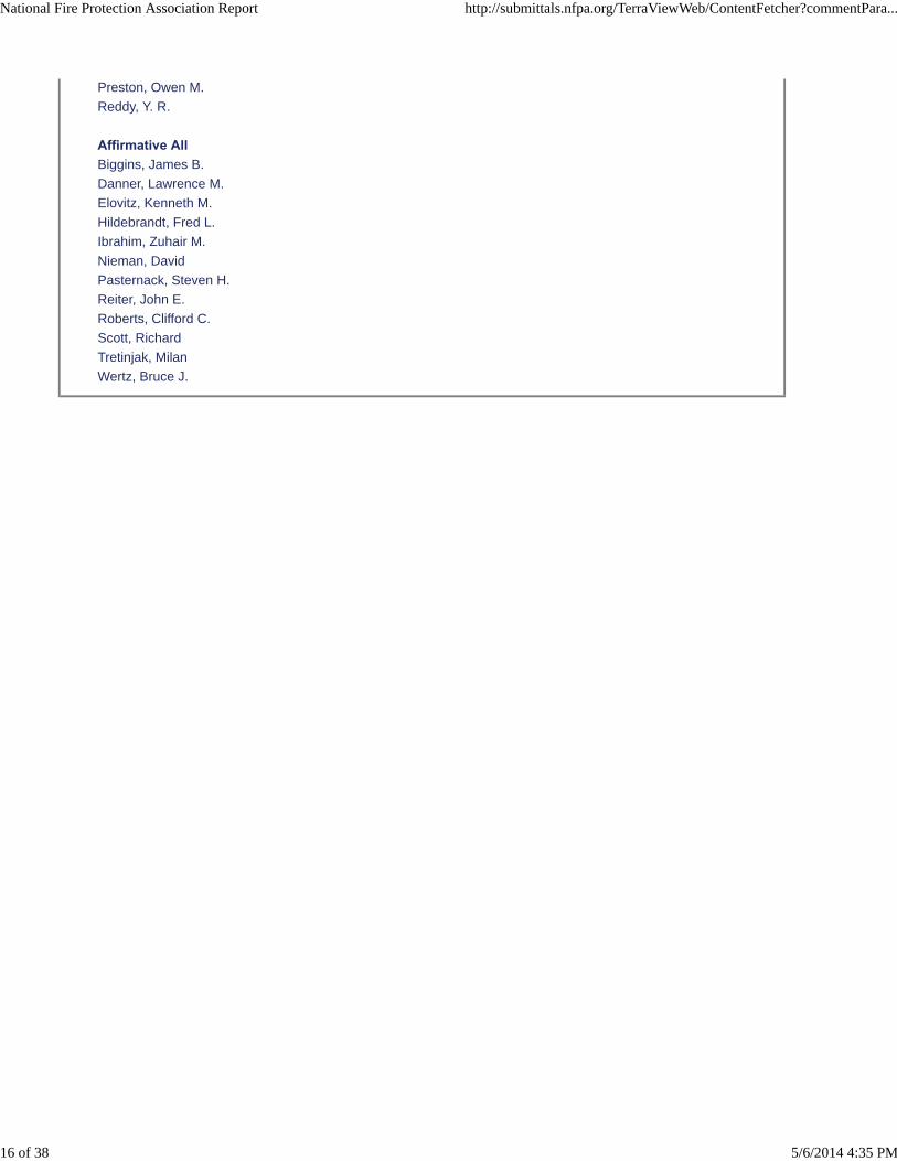
Preston, Owen M.
Reddy, Y. R.
Affirmative AllBiggins, James B.
Danner, Lawrence M.
Elovitz, Kenneth M.
Hildebrandt, Fred L.
Ibrahim, Zuhair M.
Nieman, David
Pasternack, Steven H.
Reiter, John E.
Roberts, Clifford C.
Scott, Richard
Tretinjak, Milan
Wertz, Bruce J.
National Fire Protection Association Report http://submittals.nfpa.org/TerraViewWeb/ContentFetcher?commentPara...
16 of 38 5/6/2014 4:35 PM
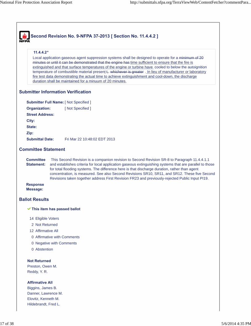
Second Revision No. 9-NFPA 37-2013 [ Section No. 11.4.4.2 ]
11.4.4.2*
Local application gaseous agent suppression systems shall be designed to operate for a minimum of 20minutes or until it can be demonstrated that the engine has time sufficient to ensure that the fire isextinguished and that surface temperatures of the engine or turbine have cooled to below the autoignitiontemperature of combustible material present t, whichever is greater . In lieu of manufacturer or laboratoryfire test data demonstrating the actual time to achieve extinguishment and cool-down, the dischargeduration shall be maintained for a minuum of 20 minutes.
Submitter Information Verification
Submitter Full Name: [ Not Specified ]
Organization: [ Not Specified ]
Street Address:City:State:Zip:Submittal Date: Fri Mar 22 10:48:02 EDT 2013
Committee Statement
CommitteeStatement:
This Second Revision is a companion revision to Second Revision SR-8 to Paragraph 11.4.4.1.1and establishes criteria for local application gaseous extinguishing systems that are parallel to thosefor total flooding systems. The difference here is that discharge duration, rather than agentconcentration, is measured. See also Second Revisions SR10, SR11, and SR12. These five SecondRevisions taken together address First Revision FR23 and previously-rejected Public Input PI19.
ResponseMessage:
Ballot Results
This item has passed ballot
14 Eligible Voters
2 Not Returned
12 Affirmative All
0 Affirmative with Comments
0 Negative with Comments
0 Abstention
Not ReturnedPreston, Owen M.
Reddy, Y. R.
Affirmative AllBiggins, James B.
Danner, Lawrence M.
Elovitz, Kenneth M.
Hildebrandt, Fred L.
National Fire Protection Association Report http://submittals.nfpa.org/TerraViewWeb/ContentFetcher?commentPara...
17 of 38 5/6/2014 4:35 PM

Ibrahim, Zuhair M.
Nieman, David
Pasternack, Steven H.
Reiter, John E.
Roberts, Clifford C.
Scott, Richard
Tretinjak, Milan
Wertz, Bruce J.
National Fire Protection Association Report http://submittals.nfpa.org/TerraViewWeb/ContentFetcher?commentPara...
18 of 38 5/6/2014 4:35 PM
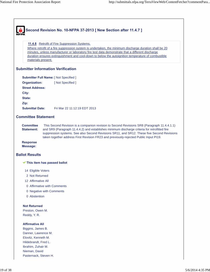
Second Revision No. 10-NFPA 37-2013 [ New Section after 11.4.7 ]
11.4.8 Retrofit of Fire Suppression Systems.
Where retrofit of a fire suppression system is undertaken, the minimum discharge duration shall be 20minutes, unless manufacturer or laboratory fire test data demonstrate that a different dischargeduration ensures extinguishment and cool-down to below the autoignition temperature of combustiblematerials present.
Submitter Information Verification
Submitter Full Name: [ Not Specified ]
Organization: [ Not Specified ]
Street Address:City:State:Zip:Submittal Date: Fri Mar 22 11:12:19 EDT 2013
Committee Statement
CommitteeStatement:
This Second Revision is a companion revision to Second Revisions SR8 (Paragraph 11.4.4.1.1)and SR9 (Paragraph 11.4.4.2) and establishes minimum discharge criteria for retrofitted firesuppression systems. See also Second Revisions SR11, and SR12. These five Second Revisionstaken together address First Revision FR23 and previously-rejected Public Input PI19.
ResponseMessage:
Ballot Results
This item has passed ballot
14 Eligible Voters
2 Not Returned
12 Affirmative All
0 Affirmative with Comments
0 Negative with Comments
0 Abstention
Not ReturnedPreston, Owen M.
Reddy, Y. R.
Affirmative AllBiggins, James B.
Danner, Lawrence M.
Elovitz, Kenneth M.
Hildebrandt, Fred L.
Ibrahim, Zuhair M.
Nieman, David
Pasternack, Steven H.
National Fire Protection Association Report http://submittals.nfpa.org/TerraViewWeb/ContentFetcher?commentPara...
19 of 38 5/6/2014 4:35 PM

Reiter, John E.
Roberts, Clifford C.
Scott, Richard
Tretinjak, Milan
Wertz, Bruce J.
National Fire Protection Association Report http://submittals.nfpa.org/TerraViewWeb/ContentFetcher?commentPara...
20 of 38 5/6/2014 4:35 PM
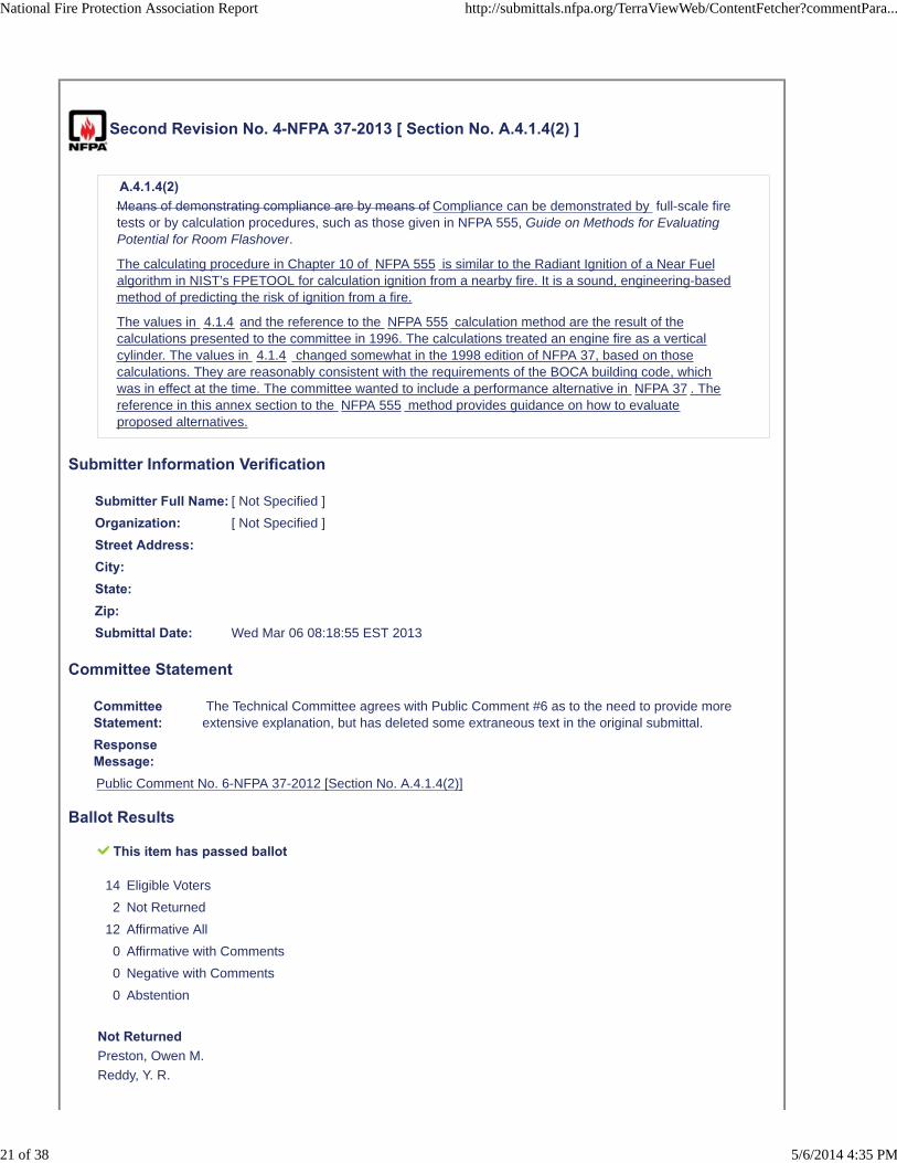
Second Revision No. 4-NFPA 37-2013 [ Section No. A.4.1.4(2) ]
A.4.1.4(2) Means of demonstrating compliance are by means of Compliance can be demonstrated by full-scale firetests or by calculation procedures, such as those given in NFPA 555, Guide on Methods for EvaluatingPotential for Room Flashover.
The calculating procedure in Chapter 10 of NFPA 555 is similar to the Radiant Ignition of a Near Fuelalgorithm in NIST’s FPETOOL for calculation ignition from a nearby fire. It is a sound, engineering-basedmethod of predicting the risk of ignition from a fire.
The values in 4.1.4 and the reference to the NFPA 555 calculation method are the result of thecalculations presented to the committee in 1996. The calculations treated an engine fire as a verticalcylinder. The values in 4.1.4 changed somewhat in the 1998 edition of NFPA 37, based on thosecalculations. They are reasonably consistent with the requirements of the BOCA building code, whichwas in effect at the time. The committee wanted to include a performance alternative in NFPA 37 . Thereference in this annex section to the NFPA 555 method provides guidance on how to evaluateproposed alternatives.
Submitter Information Verification
Submitter Full Name: [ Not Specified ]
Organization: [ Not Specified ]
Street Address:City:State:Zip:Submittal Date: Wed Mar 06 08:18:55 EST 2013
Committee Statement
CommitteeStatement:
The Technical Committee agrees with Public Comment #6 as to the need to provide moreextensive explanation, but has deleted some extraneous text in the original submittal.
ResponseMessage:Public Comment No. 6-NFPA 37-2012 [Section No. A.4.1.4(2)]
Ballot Results
This item has passed ballot
14 Eligible Voters
2 Not Returned
12 Affirmative All
0 Affirmative with Comments
0 Negative with Comments
0 Abstention
Not ReturnedPreston, Owen M.
Reddy, Y. R.
National Fire Protection Association Report http://submittals.nfpa.org/TerraViewWeb/ContentFetcher?commentPara...
21 of 38 5/6/2014 4:35 PM
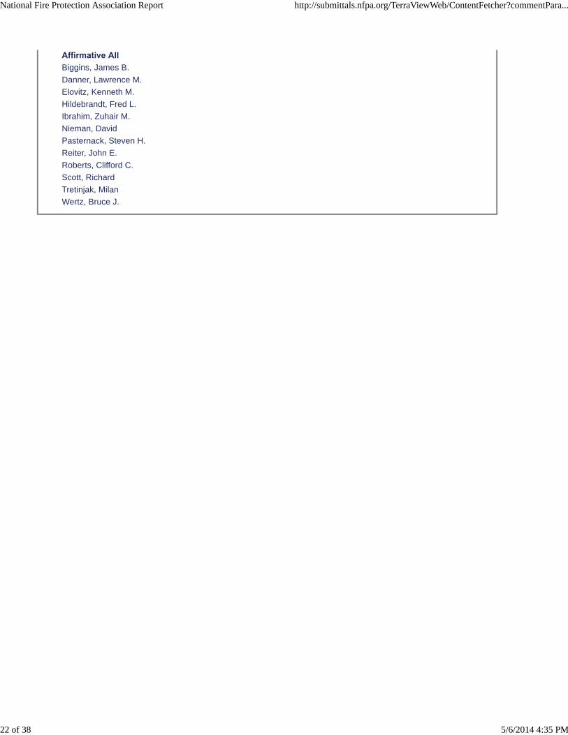
Affirmative AllBiggins, James B.
Danner, Lawrence M.
Elovitz, Kenneth M.
Hildebrandt, Fred L.
Ibrahim, Zuhair M.
Nieman, David
Pasternack, Steven H.
Reiter, John E.
Roberts, Clifford C.
Scott, Richard
Tretinjak, Milan
Wertz, Bruce J.
National Fire Protection Association Report http://submittals.nfpa.org/TerraViewWeb/ContentFetcher?commentPara...
22 of 38 5/6/2014 4:35 PM
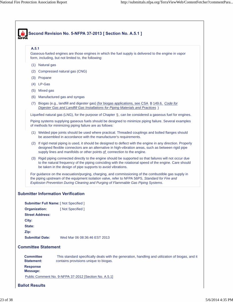
Second Revision No. 5-NFPA 37-2013 [ Section No. A.5.1 ]
A.5.1
Gaseous-fueled engines are those engines in which the fuel supply is delivered to the engine in vaporform, including, but not limited to, the following:
(1) Natural gas
(2) Compressed natural gas (CNG)
(3) Propane
(4) LP-Gas
(5) Mixed gas
(6) Manufactured gas and syngas
(7) Biogas (e.g., landfill and digester gas) (for biogas applications, see CSA B 149.6, Code forDigester Gas and Landfill Gas Installations for Piping Materials and Practices )
Liquefied natural gas (LNG), for the purpose of Chapter 5, can be considered a gaseous fuel for engines.
Piping systems supplying gaseous fuels should be designed to minimize piping failure. Several examplesof methods for minimizing piping failure are as follows:
(1) Welded pipe joints should be used where practical. Threaded couplings and bolted flanges shouldbe assembled in accordance with the manufacturer's requirements.
(2) If rigid metal piping is used, it should be designed to deflect with the engine in any direction. Properlydesigned flexible connectors are an alternative in high-vibration areas, such as between rigid pipesupply lines and manifolds or other points of connection to the engine.
(3) Rigid piping connected directly to the engine should be supported so that failures will not occur dueto the natural frequency of the piping coinciding with the rotational speed of the engine. Care shouldbe taken in the design of pipe supports to avoid vibrations.
For guidance on the evacuation/purging, charging, and commissioning of the combustible gas supply inthe piping upstream of the equipment isolation valve, refer to NFPA 56PS, Standard for Fire andExplosion Prevention During Cleaning and Purging of Flammable Gas Piping Systems.
Submitter Information Verification
Submitter Full Name: [ Not Specified ]
Organization: [ Not Specified ]
Street Address:City:State:Zip:Submittal Date: Wed Mar 06 08:36:46 EST 2013
Committee Statement
CommitteeStatement:
This standard specifically deals with the generation, handling and utilization of biogas, and itcontains provisions unique to biogas.
ResponseMessage:Public Comment No. 9-NFPA 37-2012 [Section No. A.5.1]
Ballot Results
National Fire Protection Association Report http://submittals.nfpa.org/TerraViewWeb/ContentFetcher?commentPara...
23 of 38 5/6/2014 4:35 PM
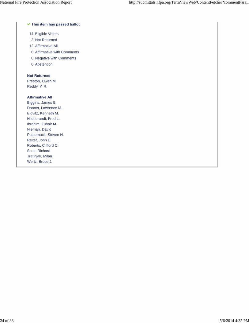
This item has passed ballot
14 Eligible Voters
2 Not Returned
12 Affirmative All
0 Affirmative with Comments
0 Negative with Comments
0 Abstention
Not ReturnedPreston, Owen M.
Reddy, Y. R.
Affirmative AllBiggins, James B.
Danner, Lawrence M.
Elovitz, Kenneth M.
Hildebrandt, Fred L.
Ibrahim, Zuhair M.
Nieman, David
Pasternack, Steven H.
Reiter, John E.
Roberts, Clifford C.
Scott, Richard
Tretinjak, Milan
Wertz, Bruce J.
National Fire Protection Association Report http://submittals.nfpa.org/TerraViewWeb/ContentFetcher?commentPara...
24 of 38 5/6/2014 4:35 PM

Second Revision No. 18-NFPA 37-2013 [ New Section after A.5.2.1(6) ]
A.5.2.1(10)
An example of an additional component might be an overpressure protection device that protectsdownstream components if the supply pressure exceeds the pressure rating of any such downstreamcomponent. Examples of such overpressure protection devices would be any of the following:
(1) A second regulator in series with the supply pressure regulator
(2) A monitoring regulator installed in series with an operating regulator
(3) A full-capacity pressure relief valve
(4) An overpressure cutoff device, such as a slam-shut valve or a high-pressure switch incombination with an adequately rated shutoff valve
Submitter Information Verification
Submitter Full Name: [ Not Specified ]
Organization: [ Not Specified ]
Street Address:City:State:Zip:Submittal Date: Wed Mar 27 19:12:57 EDT 2013
Committee Statement
CommitteeStatement:
This incorporates the basic intent of PC13, but as annex text to 5.2.1(10), instead of a mandatorynew component of the gas train. The Technical Committee determined that the use of theseoverpressure protection devices is dependent on a risk evaluation of the installation and need notnecessarily be mandated in every case.
ResponseMessage:
Ballot Results
This item has passed ballot
14 Eligible Voters
2 Not Returned
11 Affirmative All
0 Affirmative with Comments
1 Negative with Comments
0 Abstention
Not ReturnedPreston, Owen M.
Reddy, Y. R.
Affirmative All
National Fire Protection Association Report http://submittals.nfpa.org/TerraViewWeb/ContentFetcher?commentPara...
25 of 38 5/6/2014 4:35 PM
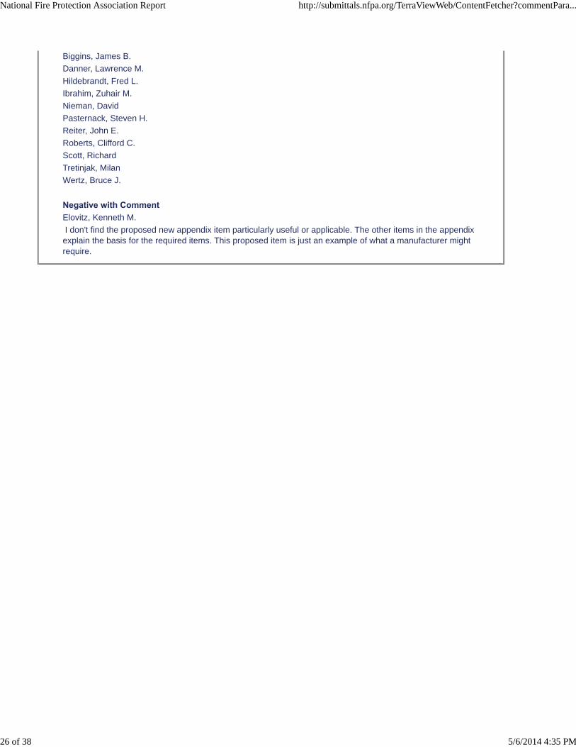
Biggins, James B.
Danner, Lawrence M.
Hildebrandt, Fred L.
Ibrahim, Zuhair M.
Nieman, David
Pasternack, Steven H.
Reiter, John E.
Roberts, Clifford C.
Scott, Richard
Tretinjak, Milan
Wertz, Bruce J.
Negative with CommentElovitz, Kenneth M.
I don't find the proposed new appendix item particularly useful or applicable. The other items in the appendixexplain the basis for the required items. This proposed item is just an example of what a manufacturer mightrequire.
National Fire Protection Association Report http://submittals.nfpa.org/TerraViewWeb/ContentFetcher?commentPara...
26 of 38 5/6/2014 4:35 PM
Second Revision No. 14-NFPA 37-2013 [ New Section after A.9.3.1 ]
A.9.3.2
While Subsection 9.3.1 provides a list of devices required to shut down the engine in case of anemergency, Subsection 9.3.2 provides a list of control features needed to ensure the safety of theengine.
Submitter Information Verification
Submitter Full Name: [ Not Specified ]
Organization: [ Not Specified ]
Street Address:City:State:Zip:Submittal Date: Wed Mar 27 14:38:09 EDT 2013
Committee Statement
CommitteeStatement:
Public Comment #3 reads as follows: "I have not provided a proposed change, rather, I amrequesting clarification in Appendix A.9.3.2 . Specifically, how does 9.3.2(4) coexist with theexception granted in 9.3.1.1 regarding a unit trip due to loss of flame?"
This Second Revision is a consequence of Public Comment #3, which pointed out aninconsistency between 9.3.1, which addresses an emergency situation, and 9.3.2, whichaddresses safety of the engine. See also Second Revision 13 for the amended version of 9.3.2(4).
ResponseMessage:Public Comment No. 3-NFPA 37-2012 [New Section after A.9.3.1]
Ballot Results
This item has passed ballot
14 Eligible Voters
2 Not Returned
12 Affirmative All
0 Affirmative with Comments
0 Negative with Comments
0 Abstention
Not ReturnedPreston, Owen M.
Reddy, Y. R.
Affirmative AllBiggins, James B.
Danner, Lawrence M.
Elovitz, Kenneth M.
Hildebrandt, Fred L.
National Fire Protection Association Report http://submittals.nfpa.org/TerraViewWeb/ContentFetcher?commentPara...
27 of 38 5/6/2014 4:35 PM

Ibrahim, Zuhair M.
Nieman, David
Pasternack, Steven H.
Reiter, John E.
Roberts, Clifford C.
Scott, Richard
Tretinjak, Milan
Wertz, Bruce J.
National Fire Protection Association Report http://submittals.nfpa.org/TerraViewWeb/ContentFetcher?commentPara...
28 of 38 5/6/2014 4:35 PM
Second Revision No. 22-NFPA 37-2013 [ Section No. A.11.4.2.3 ]
A.11.4.2.3
After the fire suppression system has extinguished the fire, the suppression agent and potentially toxicproducts of combustion should be removed from the engine enclosure and the atmosphere sampledbefore personnel without air-breathing apparatus enter for inspection or repairs. Removal is usuallyaccomplished by dilution ventilation, using a combination of exhaust and make-up air. Removal can beaccomplished by using either normal or mechanical ventilation.
Normal ventilation is natural movement of air through the enclosure or room by opening doors orwindows. In instances where rooms or enclosures are inside larger structures, care should be taken toavoid introducing contaminants into other building areas.
Mechanical ventilation systems can consist of the normal ventilation system for the room or enclosure ora dedicated purge system. Exhaust air should discharge outside the structure, away from operablewindows and outside air intakes.
In locating the exhaust air discharge, consideration should be given to both the engine enclosure andnearby structures. Chapter 15, “Airflow Around Buildings,” of the ASHRAE 1997 Handbook —Fundamentals can be consulted for guidelines on exhaust air stack height and distance from otherstructures, as well as air intakes needed to provide adequate dilution and to avoid detrimental effects ofdowndrafts.
Make-up air and exhaust openings in the enclosure should be sized and located to minimize short-circuiting. Short-circuiting occurs when make-up air flows directly from the inlet to the outlet withoutadequately sweeping through the enclosure. For suppression agents heavier than air, make-up air shouldenter high and exhaust should leave low. For suppression agents lighter than air, make-up air shouldenter low and exhaust should leave high. In either case, inlets and outlets should ideally be on oppositesides of the enclosure.
Make-up air openings in the enclosure should be sized for relatively low velocities. With sufficiently lowvelocity, the incoming make-up air tends toward “plug flow,” pushing contaminated air toward the exhaust.High-velocity incoming air would mix the make-up and contaminated airstreams, reducing thecontaminant concentration of the exhausted air.
Exhaust air openings should likewise be sized for low velocities. Higher velocities tend to create a funneleffect, leaving dead zones of contaminated air that is slow to be exhausted.
For guidance on calculating the time required to achieve a suitable atmosphere within the room orenclosure, refer to NFPA 92A , Standard for Smoke-Control Systems Utilizing Barriers and PressureDifferences , NFPA 92B , Standard for Smoke Management Systems in Malls, Atria, and Large Spaces ,or the ASHRAE and SFPE Design of Smoke Management Systems. For guidance in determiningallowable concentrations of contaminant, refer to material safety data sheets (MSDS) and permissibleexposure limits (PEL) from OSHA.
Submitter Information Verification
Submitter Full Name: Robert Benedetti
Organization: National Fire Protection Assoc
Street Address:City:State:Zip:Submittal Date: Mon Apr 15 09:03:02 EDT 2013
Committee Statement
Committee The references to NFPA 92A and NFPA 92B have been replaced with a single reference to
National Fire Protection Association Report http://submittals.nfpa.org/TerraViewWeb/ContentFetcher?commentPara...
29 of 38 5/6/2014 4:35 PM
Statement: NFPA 92. Both of the former documents have been withdrawn and replaced with the (new) latterdocument.
ResponseMessage:
Ballot Results
This item has passed ballot
14 Eligible Voters
2 Not Returned
12 Affirmative All
0 Affirmative with Comments
0 Negative with Comments
0 Abstention
Not ReturnedPreston, Owen M.
Reddy, Y. R.
Affirmative AllBiggins, James B.
Danner, Lawrence M.
Elovitz, Kenneth M.
Hildebrandt, Fred L.
Ibrahim, Zuhair M.
Nieman, David
Pasternack, Steven H.
Reiter, John E.
Roberts, Clifford C.
Scott, Richard
Tretinjak, Milan
Wertz, Bruce J.
National Fire Protection Association Report http://submittals.nfpa.org/TerraViewWeb/ContentFetcher?commentPara...
30 of 38 5/6/2014 4:35 PM
Second Revision No. 11-NFPA 37-2013 [ Section No. A.11.4.4.1.1 ]
A.11.4.4.1.1
Fire suppression system design concentrations and discharge durations should be held as long as thehazards of hot metal surfaces above the autoignition temperature and uncontrollable combustible fluidflow exist. The manufacturer should be consulted for applicable engine cool-down times. Testing hasshown this time requirement to be approximately 20 minutes, but for many cases it can be substantiallylonger. It has been shown that the initial concentration usually will not hold for a 20-minute time period inmost engine enclosures, and under these circumstances an added extended discharge is necessary toprevent potential fire reignition due to smoldering and heat soak. heavy-duty industrial engines, it can besubstantially longer. Conversely, thin-walled turbines based on aircraft engine designs cool very quickly,once fuel flow terminates. Just as discharge time might need to be increased for some heavy-dutydesigns, it is appropriate to reduce the discharge duration for aircraft engine-based turbines to less than20 minutes, based on discharge tests. Information on fire tests that demonstrate the extinguishment timefor a turbine design should also be considered in determining the minimum discharge time. It isrecommended that the minimum discharge time be no less than twice the time demonstrated to achievefire extinguishment for the suppressant used. It has been shown that the initial concentration usually willnot hold for a 20-minute time period in most engine enclosures and under these circumstances anextended discharge time is necessary to prevent potential fire reignition due to smoldering and heat soak.Where design concentrations still cannot be maintained effectively, an alternative system should beprovided.
Submitter Information Verification
Submitter Full Name: [ Not Specified ]
Organization: [ Not Specified ]
Street Address:City:State:Zip:Submittal Date: Fri Mar 22 11:30:38 EDT 2013
Committee Statement
CommitteeStatement:
This Second Revision is a companion revision to Second Revision SR8 to Paragraph 11.4.4.1.1and provides necessary explanatory information. See also Second Revisions SR9, SR10, andSR12. These five Second Revisions taken together address First Revision FR23 and previously-rejected Public Input PI19.
ResponseMessage:
Ballot Results
This item has passed ballot
14 Eligible Voters
2 Not Returned
11 Affirmative All
1 Affirmative with Comments
0 Negative with Comments
0 Abstention
National Fire Protection Association Report http://submittals.nfpa.org/TerraViewWeb/ContentFetcher?commentPara...
31 of 38 5/6/2014 4:35 PM
Not ReturnedPreston, Owen M.
Reddy, Y. R.
Affirmative AllBiggins, James B.
Danner, Lawrence M.
Hildebrandt, Fred L.
Ibrahim, Zuhair M.
Nieman, David
Pasternack, Steven H.
Reiter, John E.
Roberts, Clifford C.
Scott, Richard
Tretinjak, Milan
Wertz, Bruce J.
Affirmative with CommentElovitz, Kenneth M.
I question the advisability of inserting the words "or turbine" after "engine". The NFPA 37 definition of engineincludes turbines (see 3.3.3). Making the distinction between turbines and engines in this section potentiallyintroduces conflict or confusion unless the committee revisits the entire standard so it is clear when "engine"includes turbines and when it does not.
National Fire Protection Association Report http://submittals.nfpa.org/TerraViewWeb/ContentFetcher?commentPara...
32 of 38 5/6/2014 4:35 PM
Second Revision No. 12-NFPA 37-2013 [ Section No. A.11.4.4.2 ]
A.11.4.4.2
Fire suppression system discharge durations should be held as long as the hazards of hot metal surfacesabove the autoignition temperature and uncontrollable combustible fluid flow exist. The manufacturershould be consulted for applicable engine cool-down times. Testing has shown this time requirement to beapproximately 20 minutes, but for industrial many cases turbines it can be substantially longer.Conversely, thin-walled turbines based on aircraft engine design cool very quickly, once fuel flowterminates. Just as discharge time might need to be increased for industrial turbine designs, it isappropriate to reduce the discharge duration for aircraft engine–based designs to less than 20 minutes,based on discharge tests. Information on fire tests that demonstrate the extinguishment time for a turbinedesign should also be considered in determining the minimum discharge time. It is recommended that theminimum discharge time be no less than twice the time demonstrated to achieve fire extinguishment forthe suppressant used. An extended discharge time is necessary to prevent potential fire reignition due tosmoldering and heat soak.
Submitter Information Verification
Submitter Full Name: [ Not Specified ]
Organization: [ Not Specified ]
Street Address:City:State:Zip:Submittal Date: Fri Mar 22 11:45:03 EDT 2013
Committee Statement
CommitteeStatement:
This Second Revision is a companion revision to Second Revision SR9 to Paragraph 11.4.4.2 andprovides necessary explanatory information. See also Second Revisions SR8, SR10, and SR11.These five Second Revisions taken together address First Revision FR23 and previously-rejectedPublic Input PI19.
ResponseMessage:
Ballot Results
This item has passed ballot
14 Eligible Voters
2 Not Returned
12 Affirmative All
0 Affirmative with Comments
0 Negative with Comments
0 Abstention
Not ReturnedPreston, Owen M.
Reddy, Y. R.
Affirmative All
National Fire Protection Association Report http://submittals.nfpa.org/TerraViewWeb/ContentFetcher?commentPara...
33 of 38 5/6/2014 4:35 PM

Biggins, James B.
Danner, Lawrence M.
Elovitz, Kenneth M.
Hildebrandt, Fred L.
Ibrahim, Zuhair M.
Nieman, David
Pasternack, Steven H.
Reiter, John E.
Roberts, Clifford C.
Scott, Richard
Tretinjak, Milan
Wertz, Bruce J.
National Fire Protection Association Report http://submittals.nfpa.org/TerraViewWeb/ContentFetcher?commentPara...
34 of 38 5/6/2014 4:35 PM
Second Revision No. 21-NFPA 37-2013 [ Section No. B.1.1 ]
B.1.1 NFPA Publications.
National Fire Protection Association, 1 Batterymarch Park, Quincy, MA 02169-7471.
NFPA 13, Standard for the Installation of Sprinkler Systems, 2013 0 edition.
NFPA 20, Standard for the Installation of Stationary Pumps for Fire Protection, 2013 0 edition.
NFPA 30, Flammable and Combustible Liquids Code, 2012 edition.
NFPA 56PS, Standard for Fire and Explosion Prevention During Cleaning and Purging of Flammable GasPiping Systems, 2014 2 edition.
NFPA 68, Standard on Explosion Protection by Deflagration Venting, 2013 07 edition.
NFPA 92A , Standard for Smoke-Control Systems Utilizing Barriers and Pressure Differences , 2009edition.
NFPA 92B , Standard for Smoke Management Systems in Malls, Atria, and Large Spaces , 2009edition.
NFPA 92, Standard for Smoke Control Systems, 2012 edition.
NFPA 99, Standard for Health Care Facilities Code , 2012 edition.
NFPA 110, Standard for Emergency and Standby Power Systems, 2013edition.
NFPA 220, Standard on Types of Building Construction, 2012 edition.
NFPA 555, Guide on Methods for Evaluating Potential for Room Flashover, 2013 09 edition.
NFPA 750, Standard on Water Mist Fire Protection Systems, 2014 0 edition.
Submitter Information Verification
Submitter Full Name: Robert Benedetti
Organization: National Fire Protection Assoc
Street Address:City:State:Zip:Submittal Date: Mon Apr 15 08:55:38 EDT 2013
Committee Statement
CommitteeStatement:
The references to NFPA 92A and NFPA 92B have been replaced with a single reference to NFPA92. Both of the former documents have been withdrawn and replaced with the (new) latterdocument. See also Second Revision No. 22 to A.11.4.2.3.
ResponseMessage:
Ballot Results
This item has passed ballot
14 Eligible Voters
2 Not Returned
12 Affirmative All
National Fire Protection Association Report http://submittals.nfpa.org/TerraViewWeb/ContentFetcher?commentPara...
35 of 38 5/6/2014 4:35 PM
0 Affirmative with Comments
0 Negative with Comments
0 Abstention
Not ReturnedPreston, Owen M.
Reddy, Y. R.
Affirmative AllBiggins, James B.
Danner, Lawrence M.
Elovitz, Kenneth M.
Hildebrandt, Fred L.
Ibrahim, Zuhair M.
Nieman, David
Pasternack, Steven H.
Reiter, John E.
Roberts, Clifford C.
Scott, Richard
Tretinjak, Milan
Wertz, Bruce J.
National Fire Protection Association Report http://submittals.nfpa.org/TerraViewWeb/ContentFetcher?commentPara...
36 of 38 5/6/2014 4:35 PM
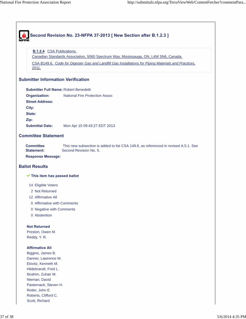
Second Revision No. 23-NFPA 37-2013 [ New Section after B.1.2.3 ]
B.1.2.4 CSA Publications.
Canadian Standards Association, 5060 Spectrum Way, Mississauga, ON, L4W 5N6, Canada.
CSA B149.6, Code for Digester Gas and Landfill Gas Installations for Piping Materials and Practices,2011.
Submitter Information Verification
Submitter Full Name: Robert Benedetti
Organization: National Fire Protection Assoc
Street Address:City:State:Zip:Submittal Date: Mon Apr 15 09:43:27 EDT 2013
Committee Statement
CommitteeStatement:
This new subsection is added to list CSA 149.6, as referenced in revised A.5.1. SeeSecond Revision No. 5.
Response Message:
Ballot Results
This item has passed ballot
14 Eligible Voters
2 Not Returned
12 Affirmative All
0 Affirmative with Comments
0 Negative with Comments
0 Abstention
Not ReturnedPreston, Owen M.
Reddy, Y. R.
Affirmative AllBiggins, James B.
Danner, Lawrence M.
Elovitz, Kenneth M.
Hildebrandt, Fred L.
Ibrahim, Zuhair M.
Nieman, David
Pasternack, Steven H.
Reiter, John E.
Roberts, Clifford C.
Scott, Richard
National Fire Protection Association Report http://submittals.nfpa.org/TerraViewWeb/ContentFetcher?commentPara...
37 of 38 5/6/2014 4:35 PM

Tretinjak, Milan
Wertz, Bruce J.
National Fire Protection Association Report http://submittals.nfpa.org/TerraViewWeb/ContentFetcher?commentPara...
38 of 38 5/6/2014 4:35 PM


![First Draft Meeting PPT - NFPA · Second Revision No. 35-NFPA 901-2015 [ Section No. 2.4 ] 2.4 References for Extracts in Mandatory Sections. NFPA 30, Flammable and Combustible Liquids](https://img.pdfslide.us/doc/110x75/602b35a525ef4411284e5ab0/first-draft-meeting-ppt-nfpa-second-revision-no-35-nfpa-901-2015-section-no.jpg)


![NFPA 1006 Second Draft Meeting Agenda 2015...Public Comment No. 101-NFPA 1006-2015 [ Global Input ] Use the following chapter numbers for the document: 1 – Administration 2 – References](https://img.pdfslide.us/doc/110x75/608babcd48566c14430bc486/nfpa-1006-second-draft-meeting-agenda-2015-public-comment-no-101-nfpa-1006-2015.jpg)