Embed Size (px)
Citation preview

1 Nor-Par_presentation_08Jul03b
Newsletter July 2003
If you are working for a producing process plant or an engineering company in Oil & Gas, Petrochemical, Chemical, Pulp and Pharmaceutical, Environmental Protection, Power, Offshore or Onshore industries, learn what benefits you can have from applying our software in your everyday work.
Head Office
President: Odd Lorentz Address: Nordstrandveien 76, 1164 Oslo, Norway Telephone: +47 22 28 69 00 Fax: +47 22 28 69 81 E-mail: [email protected]
Internet: www.norpar.com

PIPENET SOFTWARE............................................................................................................................. 51
2 Nor-Par_presentation_08Jul03b
Table of Contents
NOR-PAR A.S: COMPANY PROFILE....................................................................................................... 3 OUR OBJECTIVE ...................................................................................................................................... 4 NOR-PAR ONLINE A/S: COMPANY PROFILE ........................................................................................ 5 HOW CAN YOU BENEFIT FROM USING OUR SOFTWARE? ................................................................ 6 MULTI-DISCIPLINE SOLUTION.............................................................................................................. 10 INDUSTRIAL SOLUTION FROM NOR-PAR A.S.................................................................................... 11 THE NOR-PAR ONLINE’S TRAINING SIMULATOR & OPTIMISATION SUITE.................................... 12
PLANT2CC/PLANT2CCD: ONLINE, REAL-TIME AND PREDICTIVE PROCESS SIMULATION ......... 23 CHEMCAD SOFTWARE IS STEP COMPLIANT..................................................................................... 25 CC-SAFETY NET FROM CHEMSTATIONS INC. ................................................................................... 26 PROPLAN FROM INGENIOUS INC ........................................................................................................ 29 PROSCHED FROM INGENIOUS INC ..................................................................................................... 31 PIPENET TRANSIENT TO TRIFLEX DYNAMIC (PTR2TRD) ................................................................. 34 NOR-PAR DISTRIBUTES ALIAS LTD. PRODUCTS.............................................................................. 38 I-SKETCH FIELD ..................................................................................................................................... 39 SMART STRESS ISO .............................................................................................................................. 40 SHORT INFO ON THE REGENERATION TRAINING SYSTEM............................................................. 41 NOR-PAR A.S: SOFTWARE PRODUCTS 1 ........................................................................................... 46 NOR-PAR A.S: SOFTWARE PRODUCTS 2 ........................................................................................... 47 CHEMCAD AND OTHER CHEMSTATIONS’ PRODUCTS..................................................................... 48 TRIFLEX AND OTHER PIPINGSOLUTIONS’ PRODUCTS.................................................................... 49
MICRO TECHNO SOFTWARE................................................................................................................ 53 PLANT-4D PLANT DESIGN SOFTWARE............................................................................................... 55 CIMS 2000................................................................................................................................................ 56 MIXSIM FROM FLUENT .......................................................................................................................... 58 NOR-PAR ONLINE: PRODUCTS CATALOG ......................................................................................... 59 NOR-PAR AS AAA CREDIT RATING DIPLOMA ...................................................................LAST PAGE

Nor-Par a.s
Nor-Par a.s: Company Profile Nor-Par a.s, an international company with central office in Oslo, Norway, is presently the exclusive distributor for twelve leading engineering software vendors in Norway, Sweden, Finland, Denmark, Hungary, Poland, Czech Republic, Slovakia, Slovenia, Romania, Bulgaria, Croatia, Former Yugoslavia, Ukraine, Estonia, Lithuania, Latvia, Russia, Belarus, Germany, Switzerland, Austria, the Netherlands, Belgium, Spain, Italy, the United Kingdom as well as selected different regions: Kuwait, Saudi Arabia and Morocco.
Milestones
1959 Nor-Par a.s was established as an engineering company.
1979 The firm went into the software business, transferring its engineering activities to another company within the Nor-Par group. Nor-Par became a subcontractor to CYBERNET, world's leading online service of Control Data Corporation. CYBERNET was the first network for technical computer programs in history, allowing performing engineering calculations on mainframe computers worldwide.
1984 Nor-Par, perceiving growing capabilities of personal computers, began focusing its main interest on PC engineering software. The company was expanding its market from original Oil & Gas offshore engineering towards the Petrochemical, Chemical and Power industries.
1989 Nor-Par started operating in Central & East Europe.
1997 Nor-Par expanded its activities to be a systems integrator, introducing the Multi-Discipline Solution technology.
2000 A new sister company Nor-Par Online has been established. Nor-Par Online is a software development company to provide online training and data handling solutions for the worldwide market.
2001 Worldwide agreement with Akzo Nobel/EKA Chemicals on Online Simulation/Optimization RTS system A + B + C + D + F + G + I + Fluid Flow. PLANT2CC and PLANT2CCD made commercial products.
2002 New Development: Data reconciliation and instrument calibration tool in PLANT2CC Smart Stress Iso as the bridge between 3-D CAD, Stress Analysis and Modification Engineering
2003 New Training Simulator & Optimisation Suite. Front-end applications to CHEMCAD such as Fired Heater or Tank Farm. Nor-Par has become a distributor of Ingenious Inc products: ProPlan, ProSched.
3 Nor-Par_presentation_08Jul03b

Nor-Par a.s
Our Objective The objective of Nor-Par a.s is to offer complete technical software and related service to producing plants and engineering companies in Oil & Gas, Process and Power industries.
The key point for manufacturing industries (the Producing Plant) is to maximize profit and minimize environmental impact by:
Reducing manufacturing cost: Lowering raw material demand per unit of final product Reducing energy consumption Limiting production losses
Increasing product value: Making the product better Converting the process waste into valuable product
This can be achieved by Online, Real Time and Predictive Process Simulation (see page 23) with PLANT2CC/PLANT2CCD to:
Have a calibrated steady state process model or dynamics process/control model. This allows understanding better the way the Plant works and achieve the objectives as below:
Identify and troubleshoot the production problems Reconcile instrumentation data and re-calibrate the instruments Monitor performance of expensive equipment Optimize the production to get the best product at least energy consumption, which
can be achieved by set-point change, controller tuning Take smart decisions based on full knowledge of the process
The key point for engineering companies is to help the manufacturing industries meet the above criteria
Both engineering companies and producing plants can achieve these objectives by analyzing operating or designed processes, and applying — for process design, redesign and control — the software offered by Nor-Par a.s, on the principle of Multi-Discipline Solution (see page 10)
4 Nor-Par_presentation_08Jul03b

Nor-Par Online A/S: Company Profile Nor-Par Online is a daughter company of Nor-Par a.s focused on software development. Nor-Par a.s are the exclusive worldwide distributors of the software made by Nor-Par Online.
Objective
The goal of Nor-Par Online is to develop unique software for:
Online, Real Time and Predictive Process Simulation and Optimization
Training of Production Engineers and Plant Operators
Integration between CAD systems (including the Material Catalogs and Specs they are using) and the Multi-Discipline Solution
Major Products
Training Simulator & Optimisation Suite for training process plant engineers and operators as well as for optimization of the production
PLANT2CC for Online Process Simulation
PLANT2CCD for Real Time and Predictive Process Simulation
RTS to enhance professional skill of plant engineers
Smart Stress Iso as universal interface between 3-D CAD Systems and TRIFLEX via Alias’ I-SKETCH. This product allows re-using Material Catalogs and Specs of the 3-D CAD Systems for Modification Engineering using I-SKETCH and TRIFLEX
PTR2TRD or PIPENET Transient to TRIFLEX Dynamic which allows unique combination of dynamics loads resulting from transient fluid flow with piping stress dynamic calculations.
5 Nor-Par_presentation_08Jul03b
Nor-Par a.s
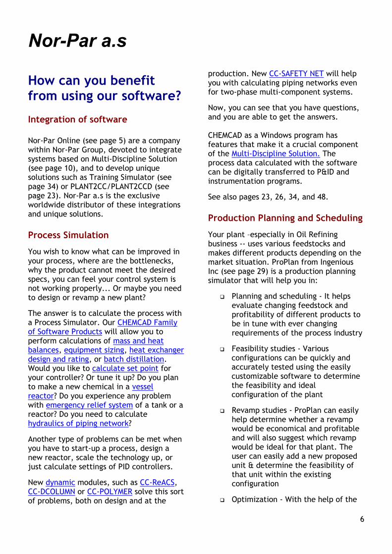
How can you benefit from using our software?
Integration of software
Nor-Par Online (see page 5) are a company within Nor-Par Group, devoted to integrate systems based on Multi-Discipline Solution (see page 10), and to develop unique solutions such as Training Simulator (see page 34) or PLANT2CC/PLANT2CCD (see page 23). Nor-Par a.s is the exclusive worldwide distributor of these integrations and unique solutions.
Process Simulation
You wish to know what can be improved in your process, where are the bottlenecks, why the product cannot meet the desired specs, you can feel your control system is not working properly... Or maybe you need to design or revamp a new plant?
The answer is to calculate the process with a Process Simulator. Our CHEMCAD Family of Software Products will allow you to perform calculations of mass and heat balances, equipment sizing, heat exchanger design and rating, or batch distillation. Would you like to calculate set point for your controller? Or tune it up? Do you plan to make a new chemical in a vessel reactor? Do you experience any problem with emergency relief system of a tank or a reactor? Do you need to calculate hydraulics of piping network?
Another type of problems can be met when you have to start-up a process, design a new reactor, scale the technology up, or just calculate settings of PID controllers.
New dynamic modules, such as CC-ReACS, CC-DCOLUMN or CC-POLYMER solve this sort of problems, both on design and at the
production. New CC-SAFETY NET will help you with calculating piping networks even for two-phase multi-component systems.
Now, you can see that you have questions, and you are able to get the answers. CHEMCAD as a Windows program has features that make it a crucial component of the Multi-Discipline Solution. The process data calculated with the software can be digitally transferred to P&ID and instrumentation programs.
See also pages 23, 26, 34, and 48.
Production Planning and Scheduling
Your plant –especially in Oil Refining business -- uses various feedstocks and makes different products depending on the market situation. ProPlan from Ingenious Inc (see page 29) is a production planning simulator that will help you in:
Planning and scheduling - It helps evaluate changing feedstock and profitability of different products to be in tune with ever changing requirements of the process industry
Feasibility studies - Various configurations can be quickly and accurately tested using the easily customizable software to determine the feasibility and ideal configuration of the plant
Revamp studies - ProPlan can easily help determine whether a revamp would be economical and profitable and will also suggest which revamp would be ideal for that plant. The user can easily add a new proposed unit & determine the feasibility of that unit within the existing configuration
Optimization - With the help of the
6

Nor-Par a.s
marginal value concept ProPlan will suggest the ideal ranges of operation of the existing units in a plant limited only by operating feasibility. Based on the chosen ranges ProPlan will carry out profit optimization for the entire complex
Impact of proprietary technology - ProPlan can be effectively used in order to demonstrate the economic impact of a technology developed or an improvement in existing technology or operation
Training and learning - ProPlan promotes better understanding within the organization about the impact of various units in the plant and also highlights the interaction of various units and the economic importance of those units in the plant
ProSched (see page 31) also from Ingenious Inc is a plant scheduling software that includes modules for feedstock scheduling, product scheduling and operations scheduling. The feedstock-schedule module facilitates quick scheduling of receipts, tank farm and blending. ProSched has the flexibility of taking input from any production planning software via macros and the Microsoft Excel interface. The feedstock-scheduling module allows the user to schedule operations that extend from the time the feedstock arrives at the loading area till the blended feed is ready to go to unit operations.
Mixing Vessels
Even if process design has been performed properly, there still can occur production problems in mixing vessels, such as inadequate dispersion of liquid droplets or solid particles in the mixed liquid, mechanical problems with a shaft,
inadequate heat transfer or excessive dead zones. You can precisely detect the source of mixing problems by advanced MIXSIM software from FLUENT, based on Computational Fluid Dynamics.
See page 58 for more details.
Fluid Flow and Piping Stress Calculations
Have your piping networks been always working properly? Never experienced 'water hammer', any pump or pipe was ever destroyed due to a surge shock? Never it happened that your pipe network was not able to deliver steam or water at desired rate? You must be a very lucky person...
In reality, flow problems occur very frequently and their results can be very costly. To be able to detect and avoid flow problems in the piping, we recommend you to use PIPENET Transient.
When you need to do steady-state hydraulics calculation for design purposes, the right module for you is PIPENET Schematic Standard. And when you scope involves fire-protection piping, you might try PIPENET Spray/Sprinkler.
(See page 51 for some more details on PIPENET.)
Well, you have just calculated transient flow, and now you know how to set-up controllers and how to protect your precious equipment. But do you know how your piping and equipment would physically react, and what is the best strategy for locating pipe supports? No. But you will discover this with PIPENET and TRIFLEX, the software used by almost whole Norwegian and Danish Oil & Gas industry. TRIFLEX calculates now stress in structural steel, not only in piping (new).
The real edge of PIPENET Transient and
7
Nor-Par a.s
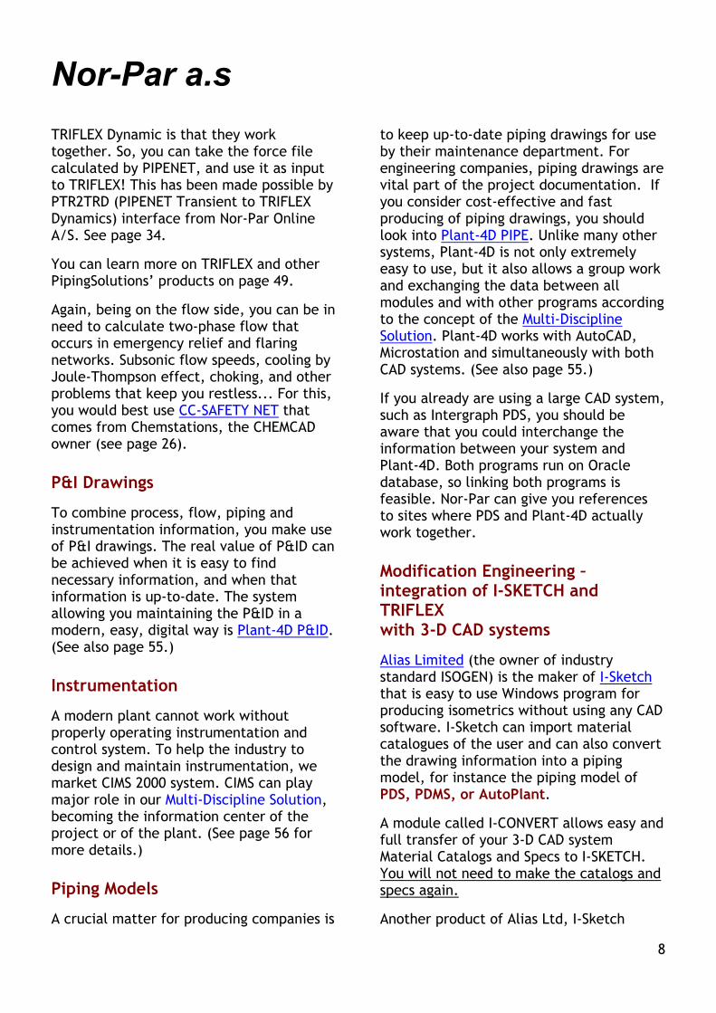
TRIFLEX Dynamic is that they work together. So, you can take the force file calculated by PIPENET, and use it as input to TRIFLEX! This has been made possible by PTR2TRD (PIPENET Transient to TRIFLEX Dynamics) interface from Nor-Par Online A/S. See page 34.
You can learn more on TRIFLEX and other PipingSolutions’ products on page 49.
Again, being on the flow side, you can be in need to calculate two-phase flow that occurs in emergency relief and flaring networks. Subsonic flow speeds, cooling by Joule-Thompson effect, choking, and other problems that keep you restless... For this, you would best use CC-SAFETY NET that comes from Chemstations, the CHEMCAD owner (see page 26).
P&I Drawings
To combine process, flow, piping and instrumentation information, you make use of P&I drawings. The real value of P&ID can be achieved when it is easy to find necessary information, and when that information is up-to-date. The system allowing you maintaining the P&ID in a modern, easy, digital way is Plant-4D P&ID. (See also page 55.)
Instrumentation
A modern plant cannot work without properly operating instrumentation and control system. To help the industry to design and maintain instrumentation, we market CIMS 2000 system. CIMS can play major role in our Multi-Discipline Solution, becoming the information center of the project or of the plant. (See page 56 for more details.)
Piping Models
A crucial matter for producing companies is
to keep up-to-date piping drawings for use by their maintenance department. For engineering companies, piping drawings are vital part of the project documentation. If you consider cost-effective and fast producing of piping drawings, you should look into Plant-4D PIPE. Unlike many other systems, Plant-4D is not only extremely easy to use, but it also allows a group work and exchanging the data between all modules and with other programs according to the concept of the Multi-Discipline Solution. Plant-4D works with AutoCAD, Microstation and simultaneously with both CAD systems. (See also page 55.)
If you already are using a large CAD system, such as Intergraph PDS, you should be aware that you could interchange the information between your system and Plant-4D. Both programs run on Oracle database, so linking both programs is feasible. Nor-Par can give you references to sites where PDS and Plant-4D actually work together.
Modification Engineering – integration of I-SKETCH and TRIFLEX with 3-D CAD systems
Alias Limited (the owner of industry standard ISOGEN) is the maker of I-Sketch that is easy to use Windows program for producing isometrics without using any CAD software. I-Sketch can import material catalogues of the user and can also convert the drawing information into a piping model, for instance the piping model of PDS, PDMS, or AutoPlant.
A module called I-CONVERT allows easy and full transfer of your 3-D CAD system Material Catalogs and Specs to I-SKETCH. You will not need to make the catalogs and specs again.
Another product of Alias Ltd, I-Sketch
8

Nor-Par a.s
Field, allows you gathering data acquisition to produce “As Is” drawings with use of a handheld PC in the field, and updating the piping model when you are back at the office. You can learn more about Alias software on page 34 and 39.
Finally, I-EXPORT allows automatic creating of new 3-D CAD models right in PDS, PDMS or AutoPlant based on I-SKETCH information.
I-SKETCH family of products is ideal for Modification Engineering:
With I-CONVERT you get Material Catalogs and Specs to be used in I-SKETCH without the need to create these again
You can import your 3-D CAD models right to I-SKETCH and start modification engineering on them in there
You can enter “As Built” status using I-SKETCH Field on a hand-held PC and automatically update the model in I-SKETCH
You can pass all technical information and piping geometry to TRIFLEX for Piping Stress Analysis using Smart Stress Iso from Nor-Par Online A/S
You can create Stress Isometric Drawings based on I-SKETCH geometry and TRIFLEX stress results using Smart Stress Iso
You can create new 3-D CAD models in PDS, PDMS or AutoPlant as the result of your Modification Engineering work.
The integration from Nor-Par Online includes Smart Stress Iso software. Smart Stress Iso first takes the piping network information (including all technical data) from Alias’ I-Sketch and uses it as input to TRIFLEX. After stress analysis in TRIFLEX, Smart Stress Iso produces Stress Isometric drawings based on I-SKETCH geometry and TRIFLEX results. This saves substantial time normally spent on manual data input to TRIFLEX, and more important, a lot of time used on manual drafting Stress Isometric Drawings in a CAD program. This also ensures data consistency throughout all engineering process involved. See page 40 for details.
You can look to Product Catalog of Nor-Par Online starting from page 59 for this and other software integration packages.
Mechanical Design
Every work requires proper tools. For thermal and mechanical design of heat exchangers, CC-THERM and MT-EXCH (page 53) will increase your productivity. CC-THERM does the thermal design and rating of shell and tube heat exchangers, while MT-EXCH performs mechanical design and automatically produces drawings in CAD format. MT-EXCH has also integration with HTRI now. For design of industrial oil storage tanks, TRITANK 650 (page 50) is just the must. MT-VESS (page 54) plays similar role in pressure vessel design and re-rating. MT-LAYOUT (see page 54) creates mechanical drawings of tubesheets and it is integrated with CC-THERM and HTRI. Other mechanical program is WERCO from PipingSolutions, which calculates stress in shells after WRC 107 and 297 Bulletin.
9

Nor-Par a.s
Multi-Discipline Solution The crucial point to effective project work is maintaining consistent documentation for all disciplines of Production or Engineering. Here is our Multi-Discipline Concept:
**) Smart Stress Iso is an integration between I-SKETCH and TRIFLEX that allows doing Modification Engineering in an effective way. It can re-use information from a 3D CAD system, such as Material Catalogues and Specs.
**) PTR2TRD is an integration between PIPENET Transient and TRIFLEX Dynamic
Production SchedulingProSched
Production PlanningProPlan
Instrumentation& Electrical
CIMS
P&ID 3D CAD
Steel Plant-4D
Isometrics I-SKETCH
3D CAD*) PDS
PDMS AutoPlant
*) Technical integration only Integration
Smart Stress Iso**)
PTR2TRD***)
Stress AnalysisTRIFLEX
Fluid FlowPIPENET
Lifecycle Workflow Solution and Engineering
Mixing Vessels
MIXSIM
Process Simulation
CHEMCAD CC-DCOLUMN
CC-ReACS CC-THERM CC-BATCH
CC-POLYMER CC-SAFETY NET
Training Simulator & Optimisation Suite
PLANT2CC
PLANT2CCD
SCADA Systemand/or Historian
Real Time or Historical Production Database
or Project Database
Now, imagine you have drawn pipelines, equipment, and instrument tag numbers by a P&ID package, and stored process data calculated with a simulator to the drawings' database. Instrumentation engineers require all these data. What happens when they change any tag number or process data? Traditionally, the documentation would become inconsistent easily. With Multi-Discipline solution the data can be updated both ways. The user can build the system from blocks and expand it as the needs grow.
10

Nor-Par a.s
Industrial Solution from Nor-Par a.s
The software and solutions provided by Nor-Par can be viewed from the point of vertical integration of information systems:
11

Nor-Par a.s
Nor-Par Online A/S software developers
Daughter company of Nor-Par a.s
The Nor-Par Online’s Training Simulator & Optimisation Suite
Beyond the traditional concepts The Nor-Par Online’s Training Simulator & Optimisation Suite offers far more than just an Operator Training System (OTS). It allows a Manufacturing Plant:
• Deep insight into the operating technology and full understanding of the nature of the process and control
• Production troubleshooting, improvements and optimisation
• Plant Operator and Production Engineer Training in start-up, shutdown, and emergency situations
• Testing alternative routes of running and controlling the production
• Online, Real Time and Predictive Process Simulation with offline, online and historical process data measurements
• Calibration of process/control models with trusted production data, online or historical
• Instrument reconciliation and control loop tuning, offline, online and with historical data
• Online monitoring of expensive equipment • Online production troubleshooting • Virtual measurement with soft sensors • Online economic calculations
The software allows a Turn-Key Engineering Company:
• Design or re-design of technologies in steady state and dynamics using offline, online or historical data approach
• Testing plant behaviour in operation, on start-up, shutdown and in emergency situations before the plant was actually built or re-constructed.
• Calculation of right set-points and controller settings taking the true nature of the process into account
• Analysis of interaction between control loops • Increasing reliability and reducing costs of
start-up or controller tuning for new or re-constructed plants
The software The Suite consists of these pieces in one delivery:
• Online Process Simulation software PLANT2CC
• Real Time and Predictive Process/Control Simulation software PLANT2CCD
• Training Simulator Controller with: o Virtual Plant management o Signal Database management o Scenario Database management
• The Engine from Chemstations o CHEMCAD o CC-DCOLUMN o or CC-ReACS o CC-THERM
Two main approaches The Suite takes two main approaches:
• The Online Process Simulation treats the measured (online or historical) data of the plant as the master for Process Simulation. This approach is ideal for an operating plant where data are available from visualization (SCADA) systems. The Online, Real Time and Predictive Simulation have been explained in PLANT2CC and PLANT2CCD presentation
• In Virtual Plant approach, a dynamic process/control model is a true “blueprint” of an operating or designed plant and it behaves and reacts to operator actions as if it were a true plant. The Virtual Plant can be calibrated by Online Process Simulation
12

Nor-Par a.s
Nor-Par Online A/S software developers
Daughter company of Nor-Par a.s
Nor-Par Online’s Training Simulator Purpose The Nor-Par Online’s Training Simulator is to be used for operator training at the producing plant. Continuous, batch and semi-batch plants can be handled. Production incidents, breakdowns, equipment failures, instrument/valve upsets, planned maintenance or emergency shutdowns, manual/auto control and set-point optimisation as well as plant start-up can be practiced. The Nor-Par Online’s Training Simulator is also to be used by Production, Engineering and R&D engineers to do Predictive Process Simulation “what if” studies. With the “what if” studies, optimal operating parameters and control settings for the plant can be found, production problem be troubleshot, and better design or re-design work can be done. Finally, the Nor-Par Online’s Training Simulator can be used for Process Optimisation driven by real production data from the plant’s control system. Six Degrees of Freedom The Nor-Par Online’s Training Simulator is unique because it gives you freedom:
1. It is based on the market standard process simulation software from Chemstations (CC-ReACS/CC-DCOLUMN) that you are already using in Production, R&D and Engineering. Most of other Training Simulators do not use a process simulator for process/control model. As the effect, only the supplier has the access to the model.
2. Your operator will be trained on your own production unit model. If your technology undergoes modifications, you are free to modify the process/control model to reflect the changes made to the plant. Most of suppliers of other Training Simulators provide very general model for single equipment such as a compressor or a steam boiler. Some other suppliers provide production unit models that only they can modify as a paid consulting
work.
3. The Nor-Par Online’s Training Simulator is focused on a plant operator who is a Chemical Engineer, not a Control Engineer. Most of competitive Training Simulators are made by DCS vendors and are focused on Automation/Control aspects.
4. Your operator will be trained in your own graphics of visualization/SCADA system. Since the SCADA graphics is yours, it will already be in the language you use in your SCADA. You are free to further customize the SCADA graphics to reflect your special needs. Most of other Training Simulators come with own graphics only in English, and only the suppliers can modify the graphics.
5. The Scenario Database is open, and the Scenarios can be defined in your own language. If you would like to modify existing scenarios or add new ones, you are free to do it. Most of other simulators come with fixed scenario database you have no access to and you cannot change the language.
6. You have the freedom to do the Training in Real Time or in acceleration to real time based on Predictive Process Simulation. Most of competitive Training Simulators offer Real Time facilities only.
The exclusive distributor of the Nor-Par Online’s Training Simulator is Nor-Par a.s, our parent company. Our plan is to provide Nor-Par Online’s Training Simulator to all technical universities in Nor-Par a.s sales territory so the students can get a valuable form of education to be later used at the process industry.
13
Nor-Par a.s
Nor-Par Online A/S software developers
Daughter company of Nor-Par a.s
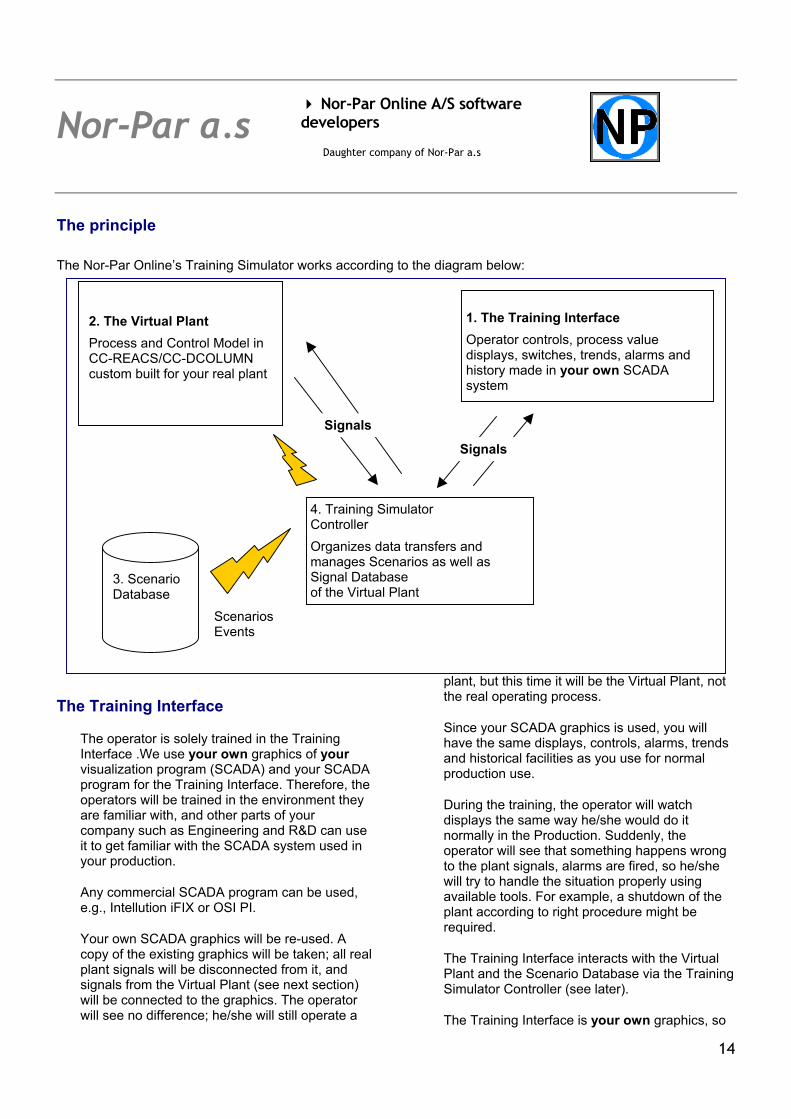
The principle The Nor-Par Online’s Training Simulator works according to the diagram below:
The Training Interface
The operator is solely trained in the Training Interface .We use your own graphics of your visualization program (SCADA) and your SCADA program for the Training Interface. Therefore, the operators will be trained in the environment they are familiar with, and other parts of your company such as Engineering and R&D can use it to get familiar with the SCADA system used in your production.
Any commercial SCADA program can be used, e.g., Intellution iFIX or OSI PI.
Your own SCADA graphics will be re-used. A copy of the existing graphics will be taken; all real plant signals will be disconnected from it, and signals from the Virtual Plant (see next section) will be connected to the graphics. The operator will see no difference; he/she will still operate a
plant, but this time it will be the Virtual Plant, not the real operating process.
1. The Training Interface Operator controls, process value displays, switches, trends, alarms and history made in your own SCADA system
2. The Virtual Plant Process and Control Model in CC-REACS/CC-DCOLUMN custom built for your real plant
Signals
Signals
4. Training Simulator Controller Organizes data transfers and manages Scenarios as well as Signal Database of the Virtual Plant
3. Scenario Database
Scenarios Events
Since your SCADA graphics is used, you will have the same displays, controls, alarms, trends and historical facilities as you use for normal production use.
During the training, the operator will watch displays the same way he/she would do it normally in the Production. Suddenly, the operator will see that something happens wrong to the plant signals, alarms are fired, so he/she will try to handle the situation properly using available tools. For example, a shutdown of the plant according to right procedure might be required.
The Training Interface interacts with the Virtual Plant and the Scenario Database via the Training Simulator Controller (see later).
The Training Interface is your own graphics, so
14

Nor-Par a.s
Nor-Par Online A/S software developers
Daughter company of Nor-Par a.s
it will be in the language you prefer and use in the SCADA. We will do the first connection of the Training Interface with the rest of the Nor-Par Online’s Training Simulator. You have the freedom of doing further modifications on your own, or by ordering the work from your SCADA consultant or from us. The modifications in the Training Interface are easy to make. The modifications you can do include:
• Modifying the structure of the SCADA flowsheets to reflect changes made to the plant
• Adding more signals from the Virtual Plant to SCADA’s Signal Database
• Adding displays/controller panels or modifying their behaviour
• Adding or modifying the Alarms and Trends
• Adding Virtual Plant signals to Historical database
Here is a sample Training Interface graphics made in Prodigy SCADA we use internally at Nor-Par Online:
No problem with your own language in Training Interface. We can provide help in English, German, Russian, Polish and Hungarian as major languages, and depending on your needs we can handle other languages of our sales area too.
15

Nor-Par a.s
Nor-Par Online A/S software developers
Daughter company of Nor-Par a.s
The Virtual Plant Your real plant consists of the process part (the producing equipment) and of the measurement & control part (field instrumentation, control valves/relays/switches, wiring, I/O area, PLC/DCS control system). PLC/DCS take care of interpreting the measured signals and applying the control strategy. Part of measurement and control signals has been provided to the operator via your SCADA system. The operator can read measured process values and he has the right to take some control decisions (e.g., set-point change, manual control.) The Virtual Plant replaces your real plant and the measurement & control part with a dynamic and calibrated process/control model in CC-DCOLUMN/CC-ReACS. As it were a real plant, the Virtual Plant is able to provide process value signals and accept control signals. From the viewpoint of the trainees, they are made to believe they operate the real plant, in the same way as a pilot is made to believe he is flying a real aircraft when he sits in a Flight Simulator. Note: The trainee does not need to see the Virtual Plant at all, because the Virtual Plant can run invisibly in the PC’s memory. All the training is done via the Training Interface, so the Virtual Plant is language independent. The Virtual Plant’s engines are CC-ReACS and CC-DCOLUMN. The process/control model that is run in these programs is your dynamic flowsheet with very minor modifications. If you only have CHEMCAD, you already have steady state models of your production. It is necessary to convert these models into valid Virtual Plant (dynamic) model. You can do it yourself, or you can order this task from Nor-Par. Note: You need a license of CC-ReACS or CC-DCOLUMN to use the Nor-Par Online’s Training Simulator. It is important that over the lifetime of your plant, you will be able to incorporate modifications done to the real plant into the Virtual Plant model yourself, so you are not dependent on a
consulting company to do the task. The Scenario Database
The Scenario Database stores Scenarios or collections of events that happen when some major incident may have happened. For example, a power loss implies, among others, that all pumps and compressors stop.
The Nor-Par Online’s Training Simulator sends these and other relevant events as direct specifications to the Virtual Plant model at the time defined in a Scenario’s event schedule. The Virtual Plant reacts to the events and the process value signals change, reflecting the true response of the plant to the Scenario events.
Several Scenarios can be scheduled to run, starting at the same time, overlapping or consecutively. For example, power loss and power up could be run in the same Scenario or in two consecutive Scenarios, depending on your preference.
16

Nor-Par a.s
Nor-Par Online A/S software developers
Daughter company of Nor-Par a.s
A sample Scenario list:
An Event is a discrete parameter change in the Virtual Plant model that occurs at specified time. One or more events simulate a real happening in the plant.It is very easy to add or modify events since an event definition is equivalent to manual setting a parameter in CC-ReACS/CC-DCOLUMN. You only need to specify the time at which such parameter change shall occur. You are free to define own Scenarios and Events as needed. You can have Scenario and Event names in your own language (e.g. English, German, French, Spanish, Swedish, Russian, Polish, Hungarian, etc.)
This is a sample Event list for the “Power loss” Scenario:
17

Nor-Par a.s
Nor-Par Online A/S software developers
Daughter company of Nor-Par a.s
Training Simulator Controller
The Training Simulator Controller organizes all data transfers in the Nor-Par Online’s Training Simulator: • Preparing Signal Database for the Virtual Plant • Editing the Scenario Database including Events and selections of the Scenarios to be run
• Starting the Virtual Plant model simulation for a specified Run Time • Executing Scenario Events and sending them to the Virtual Plant • Transferring signals from Virtual Plant to the Training Interface • Transferring signals/actions from the Training Interface to the Virtual Plant
Here is the Training Simulator Controller as used to prepare Signal Database of the Virtual Plant:
18
Nor-Par a.s
Nor-Par Online A/S software developers
Daughter company of Nor-Par a.s
Real Time (RT) vs. Predictive Process Simulation (PPS)
Nor-Par Online’s Training Simulator offers both Real Time (RT) and Predictive (PPS) training capabilities.
“Real Time” means that the Virtual Plant works at the same speed as the real plant would. The trainee will spend 2 hours by the computer to handle all events that would happen over 2 hours of true plant operation. It is common to train a plant operator in RT mode, as this reflects the reality of control room life.
However, a fresh plant operator is not familiar yet with the nature of the process he/she is to handle, and it is difficult to take right decisions without good understanding how the plant really works. A better way of providing initial training is to give the new operator a chance to self-practice by taking “what if” decisions. Let the trainee take a decision and let him/her see what would happen to the plant as the consequence of such an action. Is it practical to wait two hours to see the consequences? Certainly not, and this is why the Nor-Par Online’s Training Simulator offers the Predictive Process Simulation mode.
In the PPS mode, the Virtual Plant works 2-20 times faster that the real plant would (the acceleration factor can be predefined.) Therefore, the trainee can try many decisions and learn the consequences very quickly. The trainee can determine in, say, 3 minutes what would happen to the real plant after 30 minutes. After taking a wrong decision, the trainee can “reset” the Virtual Plant to the initial state, take a better decision and see the results very soon. This kind of “what of” studies mode gives the trainee very good
understanding of how the plant works, and this sort of training is only practical in the PPS mode.
The “what if” studies in PPS mode can be also done by the Production, Engineering and R&D employees to find optimum operating parameters of the plant, troubleshoot production problems or make better design.
The PPS feature in Nor-Par Online’s Training Simulator helps you:
In Production 1. Better understand the behaviour of your plant 2. Find optimised process parameters (such as
set-point) for more efficient and stable operation
3. Improve the control strategies 4. Find weak points in your production or
troubleshoot them In Engineering and R&D:
1. Make a better design or reconstruction of a plant
2. Analyse the effect of equipment construction and size on actual plant operation
3. Running History files of SCADA for an existing plant, find weak points and the ways to improve the re-design
4. Calculate optimum controller settings and set-points and analyse interactions between control loops
19

Nor-Par a.s
Nor-Par Online A/S software developers
Daughter company of Nor-Par a.s
Example of PPS
The plant engineer wants to see what would happen if he had:
1. Changed the set-point of controller 14TIC19 from 190 °C to 210°C 2. Used integral term in PID controller of I = 45 min and then used I = 2 min in the next trial
In the example as shown in this brochure, the realistic Acceleration Ratio of PPS is 10x against the real time. The engineer has used the Nor-Par Online’s Training Simulator and has got these results for 35 minutes of real time (each of two runs took him 3.5 minute sharp only):
Trend Displays:
Controlled tray T w ith different integral gain of the 14TIC19
185190195200205210215
0 20 40
t (min)
T (C
) I = 45 [min]
I = 2 [min]
Steam valve position with different integral gain of the 14TIC19
44
46
48
50
52
54
0 20 40
t [min]
Ope
ning
%
I = 45 [min]
I = 2 [min]
20
Nor-Par a.s
Nor-Par Online A/S software developers
Daughter company of Nor-Par a.s
C3 loss in time against integral gain
05
1015
202530
0 20 40
t [min]
C3
lost
[kg/
h]
I = 45 [min]
I = 2 [min]
Effect of integral gain Ion heat exchanger performance
13500140001450015000155001600016500
0 20 40
t [min]
Q [M
J/h]
I = 45 [min]I = 2 [min]
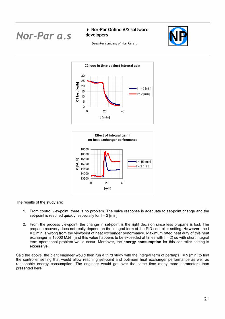
The results of the study are:
1. From control viewpoint, there is no problem. The valve response is adequate to set-point change and the set-point is reached quickly, especially for I = 2 [min]
2. From the process viewpoint, the change in set-point is the right decision since less propane is lost. The propane recovery does not really depend on the integral term of the PID controller setting. However, the I = 2 min is wrong from the viewpoint of heat exchanger performance. Maximum rated heat duty of this heat exchanger is 16000 MJ/h (and this value happens to be exceeded at times with I = 2) so with short integral term operational problem would occur. Moreover, the energy consumption for this controller setting is excessive.
Said the above, the plant engineer would then run a third study with the integral term of perhaps I = 5 [min] to find the controller setting that would allow reaching set-point and optimum heat exchanger performance as well as reasonable energy consumption. The engineer would get over the same time many more parameters than presented here.
21

Nor-Par a.s
Nor-Par Online A/S software developers
Daughter company of Nor-Par a.s
Process/Control Model Calibration; Troubleshooting; Equipment Monitoring; Process Optimisation
To have a true Virtual Plant model good for operator training, “what if” studies and further process optimisation, it is necessary to calibrate the model using trusted production data from Control System.
This can be achieved by connecting the real plant’s signals to the Virtual Plant model for online inputting the trusted measured data.
PLANT2CC/PLANT2CCD Online Process Simulation tools serve the Virtual Plant calibration purposes.
The Virtual Plant’s parameters are being adjusted as long as the Virtual Plant begins producing similar signals as those measured at the real plant. As the effect, the Virtual Plant model becomes a true “blue-print” of the real production.
From this moment, the user can analyse the process in the Nor-Par Online’s Training Simulator to find out: What are the reasons of the production problems – this is Troubleshooting Whether the plant could be operated better, perhaps by set-point changes and controller tuning – this
is Process Optimisation Whether minor changes in the equipment could help – this is also Process Optimisation Whether the equipment works properly. If not, what should be done to improve the performance. For
example, low heat transfer coefficient at a heat exchanger may mean the exchanger needs cleaning; very low tray efficiency at a distillation column might be a result of corroded trays, etc. - This is Equipment Monitoring
22

Nor-Par a.s
Nor-Par Online A/S software developers
Daughter company of Nor-Par a.s
PLANT2CC/PLANT2CCD: Online, Real-Time and Predictive Process Simulation Most of modern plants are monitored and controlled via “visualization” or SCADA*)-class technology. SCADA-class software interfaces with hardware connected to the process plant measurement sensors and output devices through Programmable Logic Controllers PLC and Distributed Control Systems DCS. SCADA systems provide visual interface in the form of mimic displays and crucially access to all ONLINE process parameters that can be downloaded to Microsoft Excel™ via data highways, for data analysis and optimization. The Online, Real Time and Predictive Process Simulation is achieved by automatically scheduled retrieval of real plant process data and equipment parameters from SCADA directly to the powerful and flexible CHEMCAD, CC-DCOLUMN and CC-ReACS process simulation software developed by Chemstations Inc. Nor-Par Online A/S has developed the PLANT2CC and PLANT2CCD software that accomplishes the SCADA/CHEMCAD integration task in online mode. This solution has successfully simulated all the economically significant chemical processes and sustainable technologies. The PLANT2CC/PLANT2CCD interface facilitates the calibration of the process model in order to reflect true plant behavior more accurately, and enables Online, Real Time or Predictive (accelerated) process optimization based on economic criteria. The Online Process Simulation**) is performed using PLANT2CC and CHEMCAD. The Real-Time and Predictive Process Simulation**) is performed with PLANT2CCD software running Dynamic modules from Chemstations Inc. Real-Time Process Simulation is the right approach to simulate and monitor large continuous plants; it is the only tool for batch and semi-batch plants; and it allows monitoring and calibration of the Control Systems. Predictive Process Simulation (PPS) allows analyzing the response of the plant to the actions in Control System or equipment in acceleration to Real Time. In other words, the person running the PPS knows in advance what will be the effect of the proposed changes in nearby future in real operating plant. *) SCADA SYSTEM / HMI / DCS CONSOLE SOFTWARE / PROCESS VISUALIZATION SOFTWARE All the terms below denote exactly the same thing: SCADA = Supervisory Control And Data Acquisition HMI = Human-Machine Interface Process Visualization software DCS console software SCADA/HMI/Visualization/DCS console is a class of software that presents data available at DCS (Distributed Control System) or PLC (Programmable Logic Controller) in a form that a human can understand. The plant personnel can also manipulate the settings of DCS/PLC directly from such SCADA systems, as a modern alternative to a traditional control room. SCADA systems come from independent software houses or from DCS vendors. The most popular independent SCADA systems are Intellution’s FIX, OSI’s PI, and Wonderware’s Intouch. **) THE ONLINE, REAL TIME AND PREDICTIVE PROCESS SIMULATION FROM NOR-PAR ONLINE A/S
PLANT2CC runs online process simulation driven by true production data in CHEMCAD PLANTCCD runs real-time or predictive process simulation driven by true production data in
CC-ReACS and/or CC-DCOLUMN
23

Nor-Par a.s
Nor-Par Online A/S software developers
Daughter company of Nor-Par a.s
MAJOR BENEFITS FROM ONLINE AND REAL-TIME PROCESS SIMULATION
Production data transferred in real time to process model for data manipulation
Calibrated process model provides transparent access to all calculated variables
Powerful production troubleshooting and instrument fault diagnosis tool
Online yield optimization and improved energy efficiency
Calculated variables from model to monitor equipment performance
Prediction of process fluid properties and compositions in real time – Virtual Measurement
Online economic calculation to reduce manufacturing costs and save energy
Instrumentation reconciliation and calibration
Calibration and tuning of control loops according to true process data
24
Nor-Par a.s
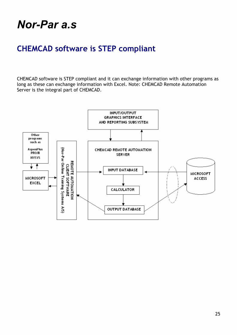
CHEMCAD software is STEP compliant
CHEMCAD software is STEP compliant and it can exchange information with other programs as long as these can exchange information with Excel. Note: CHEMCAD Remote Automation Server is the integral part of CHEMCAD.
25

Nor-Par a.s
CC-SAFETY NET from Chemstations Inc.Chemstations Inc has released a new program: CC-SAFETY NET. This program can be licensed as a standalone application for single PC or network. CHEMCAD has the CC-SAFETY NET capabilities as the standard feature.
CC-SAFETY NET provides facilities for the design and analysis of flare relief systems including all system components. These facilities include:
• Simulation of the piping network including the blowdown drum. Flow can be vapor, liquid, or two-phase, and critical flow is computed and limiting.
• Identification of the worst relieving case using case studies
• Optimization of the system using the of sensitivity analysis
• Sizing (and costing) of system equipment including pipes, relief valves, and pressure vessels.
The DIERS (Design Institute for Emergency Relief Systems) facility of CC-SAFETY NET provides the user with the latest technology in the sizing and analysis of safety relief vents in emergency situations. This technology is complex and difficult for the average
engineer to understand and apply. CC-SAFETY NET ensures that you get reliable results because:
• Chemstations has spent years studying DIERS and consulting with experts in the field. They are thus able to provide you with a tool which is not only comprehensive and accurate, but which also separates the useable from the purely theoretical providing you with a practical, real world tool.
• CC-SAFETY NET’s DIERS facility has been used in the field for years.
CC-SAFETY NET will simulate any type of steady state piping network. Flow loops, distribution systems, and collection networks can all be assembled and simulated in any combination. These networks can also include:
• Pumps, compressors, expanders, valves, pipes, fittings, heat exchangers, and pressure vessels.
• Performance curves for pumps and compressors.
26

Nor-Par a.s
CHEMCAD CC-POLYMER CC-POLYMER is an engineering software tool designed to simulate the dynamic behavior of batch, semi-batch, and continuous polymer reactors in which mixed phases exist at vapor – liquid equilibrium, but polymerization takes place in liquid phase. The current version of polymer model can handle bulk, solvent, and suspension types of homo-polymerization.
The figure below provides a pictorial summary of CC-POLYMER reactor.
CC-POLYMER can be, among others, used to:
Analyze the operation of industrial polymerization reactors.
Analyze experimental data to determine polymerization mechanisms and rates.
Determine the relationship between the reactor operation mode and polymer properties.
Analyze and determine the control strategy of polymer reactor.
Perform isothermal or adiabatic simulations, which are independent of control requirements, and of heat transfer considerations.
Perform detailed simulations, which include heat transfer aspects as well as temperature, pressure and slurry level control (built-in and external control solutions are possible).
Simulate simple flowsheets (single reactor with or without auxiliary equipment) or complex systems (multiple reactors with associated equipment).
27

Nor-Par a.s
Sample typical application are depicted below:
CHEMCAD and CC-POLYMER
CC-POLYMER is a module within CHEMCAD system represented by a dynamic unit operation. It is fully integrated in CHEMCAD structure, sharing common features such as user interface, physical property databases, thermodynamic methods, plotting and reporting.
Who should use CC-POLYMER
CC-POLYMER has been designed for engineers and chemists working with Polymer Reaction technology.
28

Nor-Par a.s
ProPlan from Ingenious Inc ProPlan® is a process-planning process simulator. The product is an extremely powerful, yet user-friendly application that facilitates the optimization and planning of plant operations. An economic analysis together with flexible planning of products and or capacities may be conducted for the complete plant. The software utilizes a graphical user-interface. ProPlan simulates plant operations by performing block-by-block calculations to determine all streams (e.g. feedstock, naphtha, oils, and blended products) flowing between the various units of the plant (e.g. splitter, crude unit, FCC). The simulator uses non-linear equations to predict yields, product properties, and the consumption of utilities. Profitability is maximized employing a numerical solver that determines the optimum operating conditions and allocation of components to finished products, subject to user-specified quality concerns.
ProPlan® is the ideal application for those involved in the planning/simulation of petroleum refineries and/or related chemical facilities. The software applications include:
Planning and Scheduling
ProPlan is a very versatile tool for Production planning operations. It helps evaluate changing feedstock and profitability of different products to be in tune with ever changing requirements of the process industry.
Feasibility reports and Configurations
ProPlan is the ideal tool for conducting feasibility analysis and reports for existing or new plants/units. Various configurations can be quickly and accurately tested using the easily customizable software to determine the feasibility and ideal configuration of the plant.
Revamp Studies
ProPlan can easily help determine whether a revamp would be economical and profitable and will also suggest which revamp would be ideal for that plant. The user can easily add a new proposed unit & determine the feasibility of that unit within the existing configuration
Optimization
ProPlan is a useful tool for optimization studies. With the help of the marginal value concept ProPlan will suggest the ideal ranges of operation of the existing units in a plant limited only by operating feasibility. Based on the chosen ranges ProPlan will carry out profit optimization for the entire complex.
Impact of Proprietary technology
ProPlan can be effectively used in order to demonstrate the economic impact of a technology developed or an improvement in existing technology or operation.
Training and Learning
ProPlan promotes better understanding within the organization about the impact of various units in the plant and also highlights the interaction of various units and the economic importance of those units in the plant.
Features
Graphical User-Interface. A clean graphical user-interface assists plant modeling. The interface provides a convenient means to develop flowsheets, enter data and constraints, and review the results of the simulation. The input forms are structured so that data for crude assay, streams, all blocks, and utilities may be intuitively entered.
The Simulator. The effectiveness of the software lies in its ability to:
Simulate flowsheets representing the actual process units and streams
29

Nor-Par a.s
Utilize non-linear process sub-models for the yield equations presented in a format that is easy to understand and modify. Moreover, crude assay/recutting is a part of the simulation, therefore, a separate program is not necessary
Utilize linear programming techniques to rapidly optimize specified blends
Maximize profitability and calculate the optimum plant operating conditions for the selected design/ operating parameters
User friendly. ProPlan® requires basic training. A basic understanding of block flow diagrams and material balances is necessary. Therefore, there is a very short learning curve prior to performing simulations and generating results. The absence of any significant ‘learning period’ for the product is in itself a savings in time and resources – a convenience not altogether available with many other simulators. Other conveniences include a relatively low cost investment, concise, browser-friendly block-by-block reports, stream and property profiles, and a complete online user manual.
30

Nor-Par a.s
ProSched from Ingenious Inc ProSched is a plant scheduling software that includes modules for feedstock scheduling, product scheduling and operations scheduling. The feedstock-schedule module facilitates quick scheduling of receipts, tank farm and blending. ProSched® has the flexibility of taking input from any production planning software via macros and the Microsoft Excel interface. The feedstock-scheduling module allows the user to schedule operations that extend from the time the feedstock arrives at the loading area till the blended feed is ready to go to unit operations. The Ingenious Group has developed this state-of-the-art scheduling product. Our group has rich experience in the fields of planning, scheduling, process simulation and engineering. Along with its affiliates and partners in North America and Asia, the Ingenious Group has been marketing and providing implementation services for the popular production planning software: ProPlan®. Additionally, Ingenious has been involved in providing basic engineering and process simulation services. The sample schematic of the entire process (below) that provides links to the detail, schedule, summary and Gantt charts for each area of the process such as tanker, tank, berth, and blender can be customized.
ProSched® feedstock scheduling module facilitates the following scheduling functions:
• Day-to-day feedstock scheduling activities
• Feedstock receipts
• Tank loading, lineups and transfers
• Oil movement & storage
• Blenders/blend tanks lineups and recipes
• Inventory management
• Default and custom constraints
31

Nor-Par a.s
Features
• State-of-the-art simulation engine for evaluating feasible schedules and optimization
• Convenient and user-friendly data entry
• Modern graphical user interface (GUI) with a user-friendly method for viewing data.
• Integral, dynamic and intuitive report generation.
• Reports, schedule and Gantt charts available for individual unit operations such as berth, tank, etc.
• Complete data access and user-friendly operation
• Easy troubleshooting and modification of scheduling operations
• Quick solution and schedule optimization
• Plan Vs Actual evaluation with multiple case comparison
• Input from production planning package for Feedstock blend and recipes.
• Integrated exporting tools for exporting schedule to third party packages. Data Input/Output The user can enter data automatically via built-in macros as well as manually. ProSched® has a dynamic interface with Microsoft Excel that allows the user to have data input from third party databases and interfaces. This data is entered before the schedule is generated in ProSched®. User also has the option of manually altering that data. On the same lines, data and reports can be easily exported from ProSched® to other third party databases including Excel via ODBC exchange.
Schedule generation & Optimization
ProSched® is designed to produce schedules that can be realistically implemented in the plant. This implies schedules that meet all physical and operational constraints and also maximize material run lengths on the blenders, process units and tank movements. Operational constraints include, amongst others, such things as Minimum/maximum tank inventories (heels), Minimum and maximum inventory levels of components and products, Minimum blender run lengths, Time requirements for blender setup, tank line-up, and testing.
Often it is not possible to meet all these requirements simultaneously. In this event the system will successively relax constraints, in a user-defined order, until a schedule is achieved. The last constraints to be relaxed are tank heel and capacity limits. A schedule that requires the relaxation of heel or capacity limits is referred to as an infeasible schedule. A typical 720-hour (One month) schedule is generated. Detailed schedule for each operation is generated and the user can scroll down to get information from hour 0 to hour 720. This information is further used to generate the Gantt charts and overall schedule report. The modeling code is developed using Microsoft Visual C++, which is integral to the simulation engine. There are built-in algorithms, which contain certain predetermined rules and infeasibilities, so if the user tries to choose an infeasible production run, a window will pop up indicating the error. A schedule is optimized based on the algorithms, rules, and constraints in the model including factors such as demurization costs, tanker availability, berth capacity, tank capacity, type of feedstock, etc. A summary report is generated for each operation, indicating key variables such as inventory, capacity, output/input rate, description, service etc. Based on the algorithms the most optimized solution is obtained in a schedule run. If the desired schedule is infeasible an error message will indicate the source of the infeasibility. This allows the user to modify the constraints, revise the schedule and obtain a feasible solution.
32
Nor-Par a.s
Schedules can change during a certain period depending on changes in certain variables in the real plant. This can be reflected in ProSched® by altering the changed variable in the model and running the schedule again. The user can easily change the schedule period from 1day to 1 week to 1 month (720 hours).
Based on the information entered by the user, ProSched® determines the properties of each operation such as schedule time, cargo code/name, arrival time, supplier, amount and other specific properties
Gantt Charts & Report Generation
ProSched® graphically displays the final feasible schedule, which can be modified by user for further upsets during scheduling period. Production run is determined by its start date and time, end date and time, time runs and throughput. User can modify production runs; properties of selected run and any changes will be instantly updated on the Gantt chart.
Plan Vs. Actual
ProSched® allows the user to compare several schedule runs and also make a direct comparison between the schedule suggested by the production planning package and the actual schedule generated for that period based on realistic constraints and physical limitations of the plant. There are several reasons why the actual schedule could be different from the planned one. Some of the factors that contribute to the disparity include tanker arrival/departure times, unavailability of the desired feedstock, capacity limitations of tanks, pumping rate limitations, failure of certain pieces of equipment, unavoidable delays in certain actions etc. The ideal situation entails a perfect match between the planned and actual schedule. However that seldom occurs in the plant. Based on the realistic scenario, the schedule generated can be transmitted to the production-planning package to alter the plan based on the realistic scenario. This calls for good plan vs. actual calculations as well as integration between the planning and scheduling software.
References of Ingenious Inc (Users/Clients) 1. Statoil Corporatio 2. Kellogg Brown & Root: Process Design Group
3. Indian Institute of Petroleum 4. Petrom Ltd (Canada) 5. Shell Refinery- Brunei 6. M. W. Kellogg Ltd (UK) 7. Larson & Toubro Ltd. 8. PetroChina Corporation 9. Petronas, Malaysia 10. Coastal Corporation (El Paso Energy), USA 11. Indian Oil Corporation Ltd R&D Center 12. NCUT (Canada) 13. Fluor Daniel Corporation 14. Jacobs Engineering (previously ICF Kaiser) 15. Kuwait University 16. Indian Institute of Technology-New Delhi 17. Pennsylvania State University 18. Veco Engineering 19. BOC Gases 20. University Institute of Chemical Technology 21. Reliance Industries Ltd.
33

Nor-Par a.s
PIPENET Transient to TRIFLEX Dynamic (PTR2TRD) In many industries (power industry, offshore mining), there occur transient problems such as waterhammer, steam hammer or transient shock in highly compressed gas systems. Such problems need to be identified and possible solution found from flow viewpoint. PIPENET Transient is the right tool to do that. In existing piping systems, the network needs to be verified by Dynamic Piping Stress Analysis to determine whether the piping would stand the transient shock effect, and ways to ensure system durability from mechanical viewpoint needs to be found. TRIFLEX Dynamic is the righ tool. The situation is the following:
PIPENET Transient provides dynamic loads as the result of transient fluid flow calculation. These data are not used by fluid flow analyst
TRIFLEX Dynamic needs the dynamic loads as the input for Time History Analysis but it is difficult or impossible for the stress analyst to guess these data
The PTR2TRD interface from Nor-Par Online A/S makes PIPENET Transient talk to TRIFLEX Dynamic, so full power of both programs can be used, and 1 + 1 becomes more than 2 in the value of the complete solution. An example:
A piping network was analyzed for Code Compliance in TRIFLEX Static and the code has been met. Now there is an interesting question: will this piping stand transient effect such as waterhammer? The piping network has been coded in PIPENET Transient first:
A scenario of linear valve closure in 4 seconds was chosen.
34

Nor-Par a.s
PIPENET gave, among others, these results:
Let us use PTR2TRD interface to transfer forces from PIPENET Transient to TRIFLEX Dynamic to be used in Time History Analysis as nodal excitations.
In PTR2TRD, the user selects PIPENET force file as input and TRIFLEX Time Function and Nodal Excitation files as output:
35

Nor-Par a.s
The user selects PIPENET force labels and duration time that are to be used in TRIFLEX Time History Analysis as nodal excitations:
Then the conversion is
The output files of PTR2TRD are used as input for TRIFLEX Time History Analysis.
This is the Time Function spreadsheet of TRIFLEX Dynamic with the converted Time Functions from PIPENET Transient:
36
Nor-Par a.s
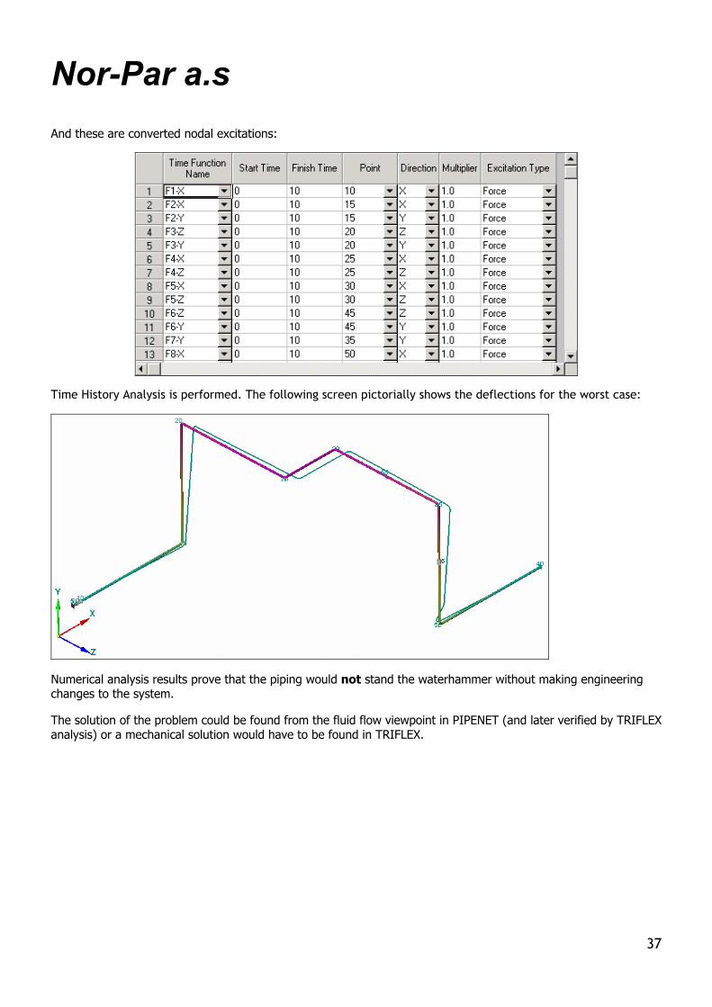
And these are converted nodal excitations:
Time History Analysis is performed. The following screen pictorially shows the deflections for the worst case:
Numerical analysis results prove that the piping would not stand the waterhammer without making engineering changes to the system.
The solution of the problem could be found from the fluid flow viewpoint in PIPENET (and later verified by TRIFLEX analysis) or a mechanical solution would have to be found in TRIFLEX.
37

Nor-Par a.s
Nor-Par distributes Alias Ltd. products I-Sketch is used where there is a requirement to produce isometrics without using a plant design system. It is implemented with full ISOGEN and can produce automatic isometrics from sketches that have been customized to the user's company standards and working practices.
I-Sketch Classic is a lower cost entry level version of I-Sketch, intended for users who need isometric capability but are not concerned with drawing customization. It is implemented with the I-GEN version of ISOGEN, but unlike I-Sketch, has no capability of integrating with the 3D model.
I-Sketch Field is a complementary tool that works with I-Sketch or I-Sketch Classic on the desktop. Operating on a Pocket PC device, I-Sketch Field revolutionizes plant piping data acquisition.
I-Convert is used to convert existing piping specifications and materials catalogues from plant design systems for use in I-Sketch.
I-Export is used to export pipes created in I-Sketch to plant design systems, stress analysis systems, or pipe spooling systems like SPOOLGEN.
SPOOLGEN takes the isometric from any design system that supports ISOGEN and provides a workflow environment for fabrication and erection information to be added by the appropriate people at the appropriate time for the production of spool isometrics.
38
Nor-Par a.s
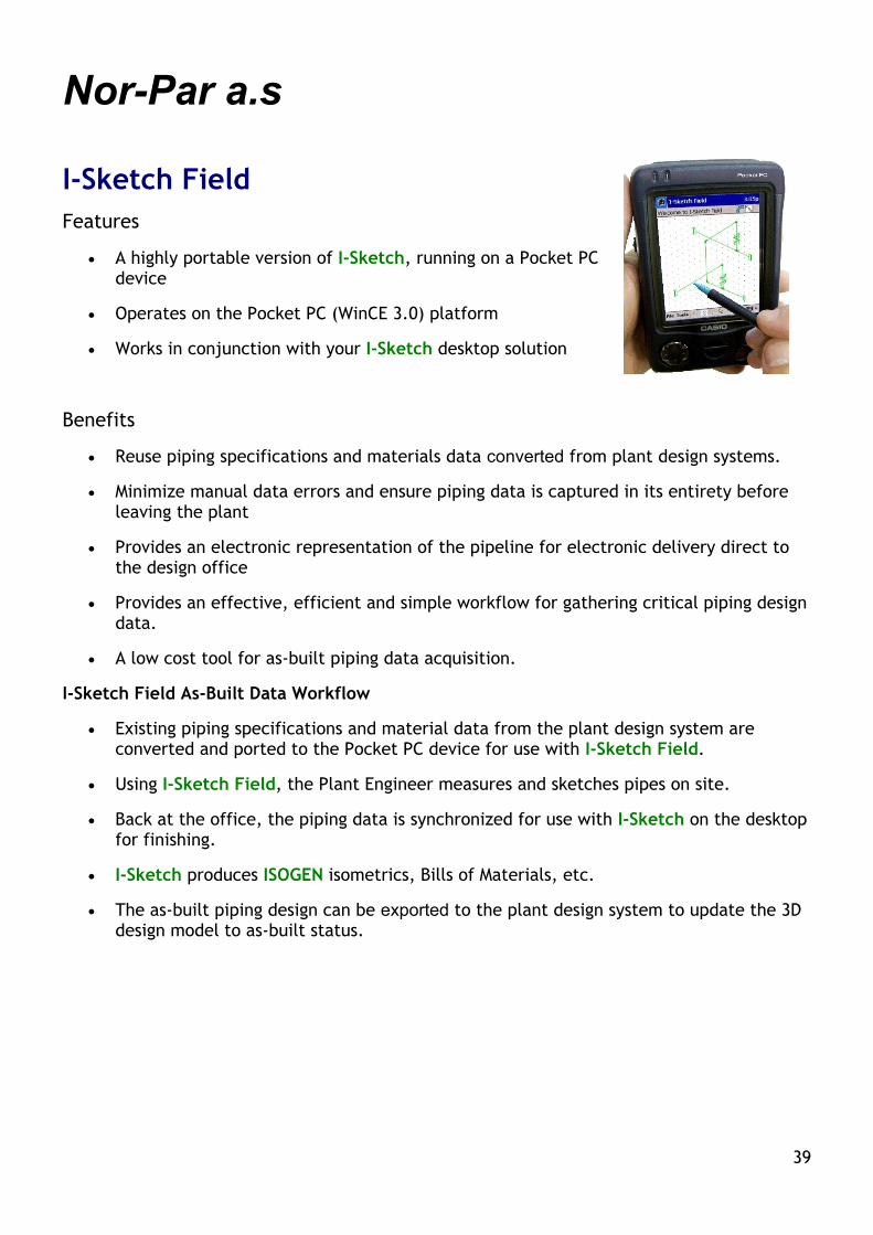
I-Sketch Field Features
• A highly portable version of I-Sketch, running on a Pocket PC device
• Operates on the Pocket PC (WinCE 3.0) platform
• Works in conjunction with your I-Sketch desktop solution
Benefits
• Reuse piping specifications and materials data converted from plant design systems.
• Minimize manual data errors and ensure piping data is captured in its entirety before leaving the plant
• Provides an electronic representation of the pipeline for electronic delivery direct to the design office
• Provides an effective, efficient and simple workflow for gathering critical piping design data.
• A low cost tool for as-built piping data acquisition.
I-Sketch Field As-Built Data Workflow
• Existing piping specifications and material data from the plant design system are converted and ported to the Pocket PC device for use with I-Sketch Field.
• Using I-Sketch Field, the Plant Engineer measures and sketches pipes on site.
• Back at the office, the piping data is synchronized for use with I-Sketch on the desktop for finishing.
• I-Sketch produces ISOGEN isometrics, Bills of Materials, etc.
• The as-built piping design can be exported to the plant design system to update the 3D design model to as-built status.
39

Nor-Par a.s
Smart Stress Iso SYSTEM FOR LIFETIME UPDATE AND MAINTENANCE OF AS-BUILT CAD/GEOMETRY
Large Plant Owner, Oil & Gas Company and Maintenance Contractors need to maintain 2-D and 3-D Geometrical data as well as Material data in 3-D CAD system throughout the whole life of a Project and later throughout whole life of the Plant.
With the System for Lifetime Update and Maintenance of As-Built Geometry the following is possible:
• Automatically transfer the Specifications from 3-D CAD systems such as PDS, PDMS, or AutoPlant to I-SKETCH from Alias Ltd (Alias are the world renowned makers of ISOGEN). The transfer is accomplished by Alias' I-CONVERT
• Import the isometric drawings from PDS, PDMS or AutoPlant into I-SKETCH
• Transfer the piping geometry and technical information to TRIFLEX for Piping Stress Analysis with Smart Stress Iso from Nor-Par Online A/S
• Do modification engineering based on TRIFLEX results in I-SKETCH
• Create Stress Isometric Drawings with Smart Stress Iso
• Automatically make new updated models in PDS, PDMS or AutoPlant using I-EXPORT from Alias Ltd.
I-CONVERT, I-SKETCH, I-EXPORT, TRIFLEX and Smart Stress Iso are delivered as the software suite.
40

Nor-Par a.s
Short info on the Regeneration Training System Why to use a computer process simulator?
A process simulator gives you opportunity to take better and smarter decisions and to get know-how. This small investment can give your company substantial savings in energy, decrease in usage of raw material, decrease in pollution load, increase in production yield, better knowledge of operated processes, and better documentation of the product.
The same cannot be achieved by hand calculations, because these give you only simplified solution of a single alternative. To identify production bottlenecks, energy losses and non-optimal heat integration you need to understand complete picture of the process. The process simulator opens possibilities to simulate thousands of alternatives, eliminate infeasible solutions, and find practical ways to overcome problems. It gives you practical and easy to use interface; physical and chemical method able to handle all technical systems, organic and inorganic, electrolytes and solids; wide range of equipment models, steady state and dynamic (such as reactors, heat exchangers, distillation/absorption, adsorption, to name a few); real control systems; sizing, environmental, and cost calculations; and batch technology facilities.
Eventually, optimal savings in the existing production can be found only by dynamic simulation. This is because hand calculation or steady state simulations describe theoretical solution of the problem only. In real production, actual behavior of a process depends on many factors, such as control system performance, actual heat and mass transfer, utilities availability, etc., all of these being parameters depending on time.
Does it really help you?
However, your real problem is human resources. People who know your production issues left the university many years ago. How to find a person who can combine practical production knowledge of your production with theoretical background, and can use advanced process simulator? How to find a person who can gather missing data, and apply practical solutions by steady state and dynamic simulation based on good understanding of theory at your production?
How can your employees get knowledge needed to operate process simulator?
The solution is to give your employees who know production issue the opportunity to refresh their knowledge on simulation theory combined with practical hints and advise.
Nor-Par a.s has developed a Regeneration Training System, a series of books/systems from mass and heat balance simulation to mass transfer, heat transfer, kinetics, and dynamic simulation. For list of book/system, see enclosure. Each of these books/systems begins with a description of benefits that the producing plant can get, and it includes many practical examples.
You can download the first chapter that tells you the benefit, and the index so you know all
41

Nor-Par a.s
the chapters in the book/system. After that you can order, pay and get as file the book/system or several books/systems.
List of books/systems
Check the book/system of interest
A Steady State Mass and Heat Balance Simulation
B Modern Thermodynamics
C Principles of Dynamic Simulation
D Dynamic Flowsheet Simulation with use both of Vessel Reactors and Reaction/Kinetic Data.
F Dynamic Flowsheet Simulation with Dynamic Distillation
G Mass Transfer in Distillation
I Electrolytes (Thermodynamics and calculations of inorganic and environmental protection systems)
J Principles and Theory of Transient Fluid Flow
K Dynamic Piping Stress
Pricing
Check to order Each RTS Book A - I USD 200
Each RTS Book J – K USD 300
Advisor service, per month USD 300
Rental of simulator including advisor service, per month Ask for offer
42

Nor-Par a.s
How to order and how to start working with the Regeneration Training System I. Read information about the Regeneration Training System (RTS) from related Internet pages http://www.norpar.net/rts.html Look to the Table of Contents and to the First Chapter for all books/systems in the series. II. Fill in the Application form that gives us information on your company. Specify the name of the person who will be the dedicated user of the RTS. Enter personal e-mail of the dedicated RTS user. III. You are only allowed to use the RTS on a single computer. IV. Define which part of RTS (Book/System Numbers) you need and whether you will require dedicated Adviser or not. V. Provide additional information so we can issue proper Invoice VI. Define when you intend to start using the RTS VII. When we receive all required information and confirmation that you have read and accepted our standard contract, we will issue the invoice. After receiving the payment, we will send the RTS to you and give you access to the Dedicated Adviser. VIII. The Adviser will get a copy of your order. The Adviser will only answer to the dedicated RTS user(s) over the defined period of 90 days. Note: A backup person in your company can be registered in the absence of the main User. However, only one person can use the RTS at a time. The backup user and the period when he works with the RTS in absence of the main user must be defined in writing. IX. In the end of the 90 days period, the Adviser will send you a summary, where he will tell you that, for example: A. You are recommended to use a process simulator in practice B. You are advised to go through another part of the RTS C. You are recommended to remain to be trained over next period of 90 days, or D. You have gathered all required skills and that he wishes you good luck in your future work.
43

Nor-Par a.s
Information
Company name: ___________________________________
First name, last name: ___________________________________
Phone number: ___________________________________
Fax number: ___________________________________
e-mail address: ___________________________________
Street address: ___________________________________
The full name of the only permitted user ___________________________________
___________________________________
Short description of your education, your position and short description of your plant production.
My additional preferences are:
To receive the respective systems as a printed book
To receive the solved examples for respective systems on a CD
I need to rent software for practice in the end of the training with or without adviser
I do need onsite Regeneration training in ____________________________
I want these questions additionally answered:
Note: The system is allowed for usage on a single dedicated PC as file or by a single dedicated user.
44

Nor-Par a.s
Standard Contract for the
Regeneration Training System™ (RTS)
I. The defined Regeneration Training System™ with separate parts A, B, C, D/E, F, G and I is the exclusive property of Nor-Par Online. It is protected with patent rights, copyright, and trademark. The RTS is protected by law of Norway.
II. Only the personally defined User has the right for dedicated usage of the material.
III. The RTS can only be used as a local copy on the PC of the defined User
IV. The Defined User can only keep one printed copy of the book(s). The book(s) or file(s) must not be given or made available to any other person, directly or indirectly.
User Statement
A. I, _____________________of Company ____________________________________,
identified by the e-mail address________________________, am the defined User that
will observe the rules of this Contract, and I understand that direct or indirect misuse
of the RTS will be prosecuted.
B. I, the defined User, confirm I understand this Contract and I will respect it.
__________________
Signature
Date: ___/____/____
45

Nor-Par a.s
Nor-Par a.s: Software Products 1
By Vendor By Application Product names
Nor-Par Online
Online process simulation/optimization Real time/predictive process simulation Operator and engineer training
Process Simulation Teaching
Integration of 3-D CAD systems with I-SKETCH and TRIFLEX
Integration of PIPENET Transient with TRIFLEX Dynamic
PLANT2CC PLANT2CCD Training Simulator & Optimisation Suite
Regeneration Training System
Smart Stress Iso
PTR2TRD
Chemstations, Inc.
Process Simulation: Steady State Flowsheet Simulation Dynamics: Reaction and Distillation Dynamics Flowsheet Simulation Environment Protection Reports (WAR)
CHEMCAD, CC-ReACS, CC-DCOLUMN. CC-THERM, CC-BATCH, CC-POLYMER, CC-SAFETY-NET, Standalone versions of these, Add-on versions of these
PipingSolutions, Inc. Stress Analysis, Mechanical Design, Welding
TRIFLEX Windows, TRI*TANK 650, WERCO
Sunrise Systems Ltd. Fluid Flow PIPENET: Transient, Standard Schematic, Spray/Sprinkler
Ingenious Inc Production Planning Simulation
Production Scheduling
ProPlan
ProSched
Alias Limited makers if ISOGEN Isometrics CAD
I-Sketch, I-Sketch Classic, I-Sketch Field, I-Convert, I-Export, SPOOLGEN
46

Nor-Par a.s
Nor-Par a.s: Software Products 2
By Vendor By Application Product names
CEA International B.V P&ID and Piping CAD Plant-4D: 2D P&ID, 3D PIPE, 2D-sections, Equipment & Steel, Component Builder, Virtual Reality Viewer,
MICRO TECHNO snc Mechanical Design of Heat Exchangers
MT-EXCH, MT-COMP, MT-VESS, MT-LAYOUT
CIMS Software Systems Instrumentation and electrical design CIMS 2000
Fluent, Inc. Mixing Vessels, Vessel Reactors MixSim
Nor-Par a.s Systems Integration Multi-Discipline Solution
47

Nor-Par a.s
CHEMCAD and other Chemstations’ products Chemstations Inc., Houston, TX, USA. See also: http://www.chemstations.net/
Integrated system for steady-state, dynamic, reaction, and batch distillation simulation, including heat exchanger design and rating module.
The system consists of these integrated modules:
CHEMCAD
CC-ReACS, Dynamics and Reaction Simulation Software, also available in Standalone and add-on versions
CC-DCOLUMN
CC-BATCH
CC-THERM (+ Air Cooled Heat Exchanger and Plate & Frame Heat Exchanger)
CC-POLYMER
CC-SAFETY NET
Key Advantages
Extremely easy to use: draw the flowsheet first, enter the data, calculate, get the results
All modules are integrated and share the data
Physical property database, DIPPR. Binary Interaction Parameter database, DECHEMA
Over 30 thermodynamic methods to select from
Crude oil properties, Amines, Sour Water,
Highly non-ideal chemicals
Electrolytes
Solids
Customizable Cost Engineering feature
Models and external programs written by the user can be executed
48

Nor-Par a.s
TRIFLEX and other PipingSolutions’ products PipingSolutions, Inc., Houston, TX, USA. See also: http://www.pipingsolutions.com
TRIFLEX: Piping Stress Analysis
TRIFLEX is renowned piping stress analysis software.
FEATURES
TRIFLEX sustained stress and displacement stress calculation "automatically" consider if pipe moves away from a restraint in the operating analysis
Built-in data bases with user definable options for nonstandard materials and vendor specific valve & flange weights AISC structural shapes included in database Advanced FRP pipe analysis
Option to use operating temperature modulus of elasticity for analysis of high temperature systems
Modeling of Jacketed Piping
Advanced coding features for faster model input
Anchor element allows different stiffnesses in all 6 degrees of freedom on one screen with option to "automatically" calculate anchor displacement Built-in buoyancy with offshore riser design codes
Pitch and Roll to vary gravity axis
ASME Section 3 analysis for calculation of nozzle and branch connection stresses and flexibilities
SIF and Flexibility Factor equations included
Automatic spring hanger sizing with piping analysis or stand alone matched with other vendor tables
Nozzle release option at equipment connections for spring hanger sizing
Directional restraints, limit stops, and friction can easily skewed using "tilt" options
Limit stop element allows different gap spacing in each direction with restraint stiffness option
Dynamic Analysis: Mode shapes and frequencies, response spectrum, and "true" time history analysis with integrated waterhammer and relief valve synthesizers. Unique closed form solution algorithms provide the most accurate technology available for analyzing piping responses to slug flow, waterhammer, steam thrust, and other transient loads. Code reports provide minimum wall thickness with user definable mill tolerance
Flange Loading Compliance Report
Rotating Equipment Compliance Reports (TRIFLEX automatically transfers forces and moments from piping analysis to equipment nozzles)
NEMA SM 23: Steam Turbines
API Standard 617: Centrifugal Compressors
API Standard 610: Centrifugal Pumps
ROT: Client customized report using vendor supplied allowables
49

Nor-Par a.s
Piping Code Compliance Reports ANSI/ASME B31.1, B31.3, B31.4, and B31.8
ASME Section 3, Class 2 and 3
U.S. Navy Piping Code
Norwegian and Swedish Piping Codes
DNV (including DNV 2000), Statoil, and NPD offshore riser codes
Polska (Polish) Norma PN-79 / M34033d
SNIP 2.05-06-85 Russian Transmission Piping Code
EN 13480-3 Euro Code
UK 00A British Offshore Code
DIN 2413 Wall Thickness
New Features:
Calculation of stress in structural shapes in addition to piping stress
Advanced transfer of graphics to AutoCAD DXF
TRITANK 650
TRITANK 650 is a comprehensive software package for the design and rating of welded steel oil storage tanks in accordance with API Standard 650, 8th and 9th Editions.
TRITANK 650 APPLICATIONS
Technical compliance and documentation for regulatory authorities
Designs new tanks and re-rates existing tanks
Calculates shell plate thickness and weights
Provides detailed tank drawings
50

Nor-Par a.s
PIPENET software Sunrise Systems Ltd., Cambridge, UK. See also: http://www.sunrise-sys.com
PIPENET is a powerful software tool for flow analysis of pipe and duct networks.
PIPENET starts at the design phase, providing the means of performing calculations such as pipe sizing and pump selection under steady state conditions. At the other end of the spectrum, PIPENET computes the transient forces necessary for pipe stress analysis and pipe support design under transient flow conditions.
PIPENET Standard Schematic is the perfect tool for solving general flow problems with liquids, gases, or steam
PIPENET Transient is ideal for unsteady state problems such as "water hammer", "steam hammer", and calculation of hydraulic forces necessary for piping stress analysis
PIPENET Spray/Sprinkler is exceptional for the design of fire protection systems, whether they be deluge, ringmain or sprinkler
PIPENET Standard Schematic
The PIPENET Standard Schematic is for general flow analysis in networks of pipes or ducts, carrying liquids, steam or gases.
Key features
Water properties are built-in and steam properties comply with the IFC67 Standard. A database of gases is provided in the program to which user-defined gases can be added
The network can be as simple or as complex as necessary, and can be made of pipes, ducts, fittings, pumps, fans, check valves, control valves, nozzles, filters, orifice plates and other models. Control valves can be set for pressure, flow, differential pressure or valve position. The range of fittings available in the program is from Crane manual. The user can add others, which can be stored in a library.
The Standard Schematic module has powerful pipe sizing capability. The user can define pipe schedules from which the program will select appropriate nominal sizes.
Pumps and fans can be connected in parallel or in series anywhere in the network. Libraries or pumps and fans can be created with a dedicated option, then the library items would be inserted anywhere in the network.
Many useful features exist, such as checking for cavitation, correction for ambient pressure with height, calculation of hydraulic gradients and modeling of leaks.
51

Nor-Par a.s
PIPENET Transient
The PIPENET Transient module provides a speedy and cost-effective means for in-house rigorous transient analysis. It can be used for predicting pressure surges, calculating hydraulic transient forces or even modeling control systems in flow networks.
Water hammer
Surge analysis
Hydraulic transient forces
Cavitation modeling
Graphical and tabular output
Key features
Transient module can model networks with items such as pipes, operating valves, variable speed pumps, air release and vacuum breaker valves, accumulators, pressure and flow transmitters, PID controllers and transfer functions to represent the dynamics of instruments and valves.
Not only can Transient predict cavity separation, it can actually model its formation and collapse. A wide choice of functions and tables are available for setting up boundary conditions.
Transient can find its own initial and final steady states or use initial values given by the user. The time step for calculation can be determined by the program or specified by the user, as can time steps for tabular, graphical, and forces output.
With Transient any variable can be selected by the user to be output in graphical and tabular form. Hydraulic transient forces can be output to a separate file, which can be then used by the pipe stress analysis program, TRIFLEX, for further processing.
PIPENET Spray/Sprinkler
The PIPENET Spray/Sprinkler module is specially developed for the design of fire protection systems in accordance with the NFPA13 and NFPA15 rules. The Spray/Sprinkler module is ideal for all types of water-based systems, including deluge, ringmain, sprinkler and foam solution systems.
NFPA13, NFPA15
Deluge, ringmain, sprinkler
Fire pump selection
Most remote nozzle option
Multiple pipe types
52

Nor-Par a.s
Micro Techno software MICRO TECHNO snc, Ciampino, Italy See also: http://www.microtechno.com
MT-EXCH: MECHANICAL CALCULATION OF SHELL & TUBES HEAT EXCHANGERS
The MT-EXCH program allows the mechanical design and the stability check of shell & tubes heat exchangers, and it automatically produces drawings In CAD format.
Now, MT-EXCH is integrated with CC-THERM and HTRI
ANALYSIS CAPABILITIES
Internal pressure calculation All the exchanger components, shell side and tube side, are calculated to the internal conditions of design and hydraulic test. The components in contact with both the shell side and the tube side are automatically checked to the pressure acting on the external side.
Geometrical sizing of the exchanger The program provides for a comprehensive geometrical sizing including all the quotas, distances and dimensions of each component and of the exchanger as a whole. The reference to constructive standards included in the program manual allows the user to have quickly the rated setting plan of the exchanger.
Weight calculation The program calculates all the weights of the singular components and in addition: - Empty weight of the exchanger - Weight of the tube bundle - Weight of the exchanger full of water
Check to the external pressure The program allows for the installation of stiffening rings or for the thickness increasing or for a combination of the two possibilities.
Stability check to the combined effects of forces and moments generated by the exchanger weight, by the wind and earthquake loads, and by forces and moments specified by the user. The resultant forces and moments are applied to the supports for the stability checks and the calculation of loads acting over the foundations.
Supports positioning and stability checks - Saddles, the check is carried on according to the method of Prof. Zick - Brackets, the check is carried on according to the method of Prof. Bijlaard and B.S.5500
53

Nor-Par a.s
MT-VESS: Pressure Vessel Mechanical Design
Programs that form the MT-VESS package perform:
Global design of a pressure vessel including mechanical and geometrical sizing
Design of base components
Standards
ASME VIII Division 1
ISPESL-VSR (Italian)
Databanks
Heat exchanger material classes
Pressure vessels material classes
Mechanical characteristics of materials
Nozzle database
Gaskets database
Vacuum charts database
Supports database
Vessel Design
Sizing to the combined effects of temperature and pressure
Calculation of loads--apart the pressure--that stress the vessel
Weights Forces generated by wind Forces generated by earthquake Support reaction Additional loads
Check to the tensions and to the deformations due to the forces as above
MT-LAYOUT: Tubesheet Layout Drawing Program
MT-LAYOUT automatically makes CAD drawings of tubesheets.
MT-LAYOUT is integrated with CC-THERM and HTRI
54

Nor-Par a.s
Plant-4D Plant Design Software CEA International B.V, Rotterdam, The Netherlands See also: http://www.cea-int.com
PLANT-4D is an unique object-oriented Plant Design software tool, which can be operated without being restricted to a single CAD platform. The PLANT-4D technology ensures full transparent compatibility between different CAD platforms (both for drawings and data). It is possible to work on a project for instance in AutoCAD, and continue with the same project in MicroStation, without losing one bit of information or functionality. The PLANT-4D Object/Data Technology is the driving force behind the new generation in Plant Design Software. All the Graphic and Data information is 100% stored in a neutral database.
Plant-4D P&ID allows creating intelligent piping and instrumentation diagrams, and the intelligence exists in the drawing database even when you don't know all necessary data beforehand, and you can manage data at any stage of the project work. The data are available to all other modules at the moment you have entered them.
Plant-4D PIPE lets you create and edit 3D model of piping and manage any piping, instrumentation, process or maintenance data. The data become available to other modules such as P&ID at the moment you have modified or entered them. 2D piping layouts can be generated from the 3D model.
Plant-4D Equipment/Steel module is specially suitable for the drawing of Equipment and Steel Constructions.
Plant-4D to ISO integrates Plant-4D PIPE with I-GEN or ISOGEN from Alias Ltd. (a part of Plant-4D licence), andit allows automatic generation of Isometric Drawings based on 3-D piping model.
Component Builder allows creating the 3D components used for piping drawings in minutes.
Virtual Reality Viewer enables you to "walk through" the 3D plant model and see it from any angle without need to use a CAD interface.
Interfaces
Plant-4D is ideal for interfacing with other programs. Here are examples of possible integration:
CHEMCAD -> Plant-4D transfers process data from CHEMCAD simulation to the Project Database of Plant-4D
Plant-4D -> CIMS 2000 transfers Tag Numbers and Process Data from Plant-4D to CIMS 2000 Instrumentation Design system
Plant-4D -> TRIFLEX transfers all required information from 3-D piping model including network topology and technical data to TRIFLEX, so need of manual input to stress analysis program is minimal.
55

Nor-Par a.s
CIMS 2000 CIMS Software Systems, Antwerp, Belgium. See also: http://www.cims2000.com
CIMS 2000: Instrumentation and Electrical design
CIMS™ 2000 is a PC-based, configurable system that helps you manage Instrumentation & Electrical (I & E) related information for your engineering projects and maintenance related tasks according to your standards, rules and preferences.
It is unique by being fully configurable to your specific requirements without requiring in-depth software programming knowledge.
CIMS™ 2000 provides an efficient engineering project system, as well as an organizational tool for maintaining I&E related documents and drawings through the industrial plant life-cycle.
Main Features
Data management module that handles:
Instruments Index
Lists for: Equipment, pipe-lines, electric motors, Control systems Input/Output and others
Process data management
Data sheets (for: instruments, equipment, electrical devices etc.)
Wiring & cabling
Instruments installation ("Hook-Up") drawings
Powerful report writer
Database driven drawings creation
Wiring drawings
Loop diagrams (Drawings are generated using Microstation® and Autocad®)
Calculations for:
Flow elements
Control valves
Relief valves (Using Conval 5.0 by F.I.R.S.T)
Electrical design
Area Type and Safety Regulations
56

Nor-Par a.s
57
Motor characteristics
Starter equipment
Cable types and naming conventions
Electrical Typicals: General, Cable List, IO Point List, Accessories List
Lists of Consumers
Electrical wiring design
MCC cabinets
Standard Electrical Drawings
Cable Wiring
Electrical Typical Schematics
One Line Diagrams
Audit-trail
Database Driven
Friendly X-Base (DBF) inherent structure and commands or Open DataBase connectivity (ODBC) for using other RDBM's MS-SQL Server™ and Oracle™
Communicates with third party packages through database mechanisms
Import/Export
CAD independent
Generates drawings for AutoCAD and MicroStation
You teach the program to build any possible sort of electrical drawing you wish
Fully configurable to fit all possible user needs
Database structure is completely configurable
Input is 100% configurable. You can create any new data input dialogs
Reports are 100% configurable. You can create any report or specification right in the program
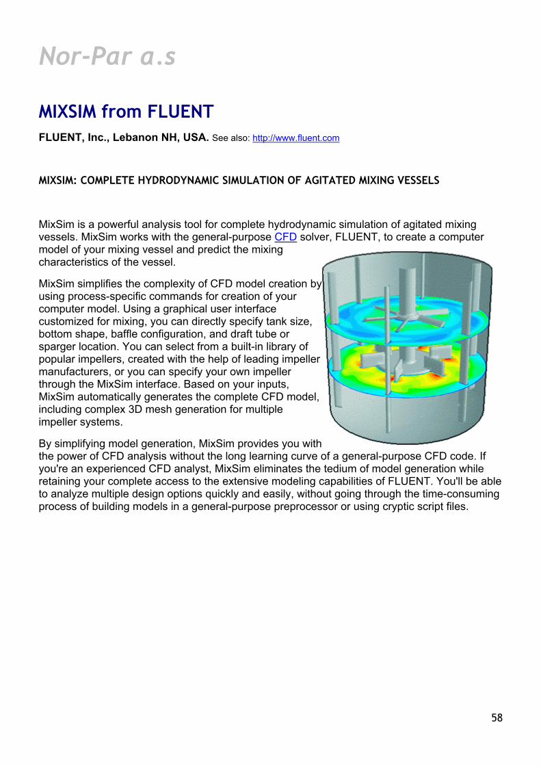
Nor-Par a.s
MIXSIM from FLUENT FLUENT, Inc., Lebanon NH, USA. See also: http://www.fluent.com
MIXSIM: COMPLETE HYDRODYNAMIC SIMULATION OF AGITATED MIXING VESSELS
MixSim is a powerful analysis tool for complete hydrodynamic simulation of agitated mixing vessels. MixSim works with the general-purpose CFD solver, FLUENT, to create a computer model of your mixing vessel and predict the mixing characteristics of the vessel.
MixSim simplifies the complexity of CFD model creation by using process-specific commands for creation of your computer model. Using a graphical user interface customized for mixing, you can directly specify tank size, bottom shape, baffle configuration, and draft tube or sparger location. You can select from a built-in library of popular impellers, created with the help of leading impeller manufacturers, or you can specify your own impeller through the MixSim interface. Based on your inputs, MixSim automatically generates the complete CFD model, including complex 3D mesh generation for multiple impeller systems.
By simplifying model generation, MixSim provides you with the power of CFD analysis without the long learning curve of a general-purpose CFD code. If you're an experienced CFD analyst, MixSim eliminates the tedium of model generation while retaining your complete access to the extensive modeling capabilities of FLUENT. You'll be able to analyze multiple design options quickly and easily, without going through the time-consuming process of building models in a general-purpose preprocessor or using cryptic script files.
58

Nor-Par Online: Products Catalog Training Systems # Product name Code name Description
Training Systems
1. Regeneration Training System
RTS
A, B, G, I
C, D, F
“Transient Fluid Flow”
“Dynamic Piping Stress”
Teaching system for production personnel of process plants
Books without examples
Books with examples
Integration Software
Integration Software
2. Online and real time process simulation and optimization
PLANT2CC PLANT2CCD
Training Simulator & Optimisation Suite
Online process optimization Real time and predictive process simulation Operator training and production optimization
3. CAESAR to TRIFLEX interface
C2TR Conversion of data from CAESAR II to TRIFLEX Windows
4. Smart Stress Iso SSI Generation of Stress Isometrics in I-Sketch based on I-Sketch piping network and TRIFLEX stress analysis.
Includes I-Sketch -> TRIFLEX and TRIFLEX -> I-Sketch interfaces
5. Plant-4D to TRIFLEX interface
P4D2TR Export of piping network and technical data from Plant-4D to TRIFLEX
6.
PIPENET Transient to TRIFLEX Dynamic
PTR2TRD Transfer dynamic loads of transient fluid flow to TRIFLEX for Time History Analysis
59

7. AutoPlant to TRIFLEX interface
AP2TR Export of piping network and technical data from AutoPlant to TRIFLEX
8. PIPENET Transient to TRIFLEX Dynamic interface
PN2TR Force file export from PIPENET Transient to TRIFLEX Dynamic
9. CHEMCAD to PDS interface
CC2PDS Process data transfer from CHEMCAD to Intergraph PDS 2D
10. CHEMCAD to Plant-4D interface
CC2P4D Process data transfer from CHEMCAD to Plant-4D
11. CHEMCAD to CIMS2000 interface
CC2CIMS Process data transfer from CHEMCAD to CIMS 2000
12. Plant-4D to CIMS2000 interface
P4D2CIMS Data transfer from Plant-4D to CIMS 2000
13. X-Steel to Plant-4D interface
XS2P4D Transfers steel structures from X-Steel to 3D model of Plant-4D
14. PDS 3D to TRIFLEX*) PDS2TR Export of piping network and technical data from Intergraph PDS 3D to TRIFLEX
15. PDMS to TRIFLEX*) PDMS2TR Export of piping network and technical data from CAD Centre PDMS to TRIFLEX
16. TRIFLEX to Plant-4D*) TR2P4D Export of stress information and of piping network from TRIFLEX to Plant-4D
17. TRIFLEX to AutoPlant*) TR2A Export of stress information and of piping network from TRIFLEX to AutoPlant
18. Plant-4D to PIPENET*) P4D2PN Export of piping network from Plant-4D to PIPENET
60

Material Catalogs for CAD Software # Product name Code name Description
Material catalogs for CAD software
19. Dynamic Catalog/Spec Generator for Plant-4D*)
P4DDYNSPEC Dynamically maintains Catalog Databases and Specification Tables of Plant-4D to generate Specs with minimum effort and time
20. Nuclear Power Extension for Plant-4D
P4DCANDU Component database, Catalogs, and menus for Plant-4D to be used by Nuclear Power industries for piping design. Definitions set by CANDU rules. Includes Copper fittings, Solder Joint end-types, special components and much more
21. Extended ANSI Catalogs for Plant-4D*)
P4DANSIEXT Full ANSI material catalog for piping design, including weights. For Plant-4D
22. Polish Material Database for Plant-4D
P4DKER Polish Catalog of Piping Components (Katalog Elementow Rurowych KER) in Plant-4D
23. Polish Material Database for I-Sketch
ISKER Polish Catalog of Piping Components (Katalog Elementow Rurowych KER) in I-Sketch
24. Pharmaceutical Extension to Plant-4D*)
P4DPHARMA Component database, Catalogs, and menus for Plant-4D to be used by Pharmaceutical industries for piping design. Includes hygienic fittings, valve catalogs and much more
25. Extended DIN Catalogs for Plant-4D*)
P4DDINEXT Full DIN material catalog for piping design, including weights. For Plant-4D
26. Romanian Material Database for Plant-4D*)
P4DSTAS Romanian Catalog of Piping Components (STAS) in Plant-4D
*) Software under development
61

Local versions of software and publications # Product name Code name Description
Localized software and publications
27. Polish version of CHEMCAD
CCPL Extension to CHEMCAD for the Polish market.
Includes Polish Input, Output, Help, and User Manual on Theory
CHEMCAD portion
CC-THERM portion
CC-ReACS portion
CC-DCOLUMN portion
28. Russian version of CHEMCAD*)
CCRUS Extension to CHEMCAD for the Russian-speaking market. Includes Russian Input, Output, Help, User Manual and Tutorial
CHEMCAD portion
CC-THERM portion
CC-ReACS portion
CC-DCOLUMN portion
29. Polish Tutorials for Plant-4D
P4DPIDTUTLPL P4DPIPTUTLPL P4DSTEQPL P4DCMPBLDRPL
Polish P4D P&ID and Customization Tutorial Polish P4D PIPE Tutorial Polish P4D Steel/Equipment Tutorial with Collision practices Polish P4D Component Builder Tutorial
*) Under development
62
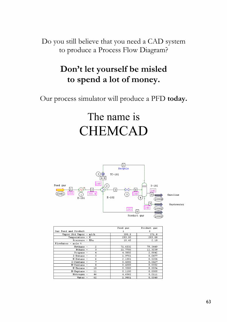
Do you still believe that you need a CAD system to produce a Process Flow Diagram?
Don’t let yourself be misled to spend a lot of money.
Our process simulator will produce a PFD today.
The name is CHEMCAD
63

64