Embed Size (px)
Citation preview

INSTALLATION/USERMANUAL
Newall Measurement Systems
DP8 Series
DIGITAL READOUTSYSTEM
Contents
Newall Measurement Systems1
ON
TE
NT
S
1.0 Introduction1.1 EMC and Low Voltage Compliance
1.2 Technical Specifications
2.0 Installation 2.1 Mounting
2.2 Power Supply
2.3 Connections
2.4 Switching On
3.0 User Instructions
3.1 Options
3.2 Using the Keypad
4.0 Set-Up
4.1 Set-Up Introduction
4.2 Set-Up Defaults
4.3 Set-Up Menu
5.0 Standard Functions
5.1 Absolute/Incremental
5.1.1 Using Incremental
5.1.2 Using Absolute
5.1.3 Establishing a datum
5.2 Centre Find
5.3 Digifind (Ref)
5.3.1 Using a machine marker
5.3.2 Using a Workpiece marker
5.3.3 Find Absolute Zero
5.4 Sub Datums (SDM)
5.4.1 Method 1 (Teach mode)
5.4.2 Method 2 (Manual Mode)
5.4.3 Job Number
5.4.4 Editing Sub Datums and Job Number
5.5 Inch/mm
5.6 Datahold (Display Off)
5.7 Zero Approach
6.0 Mill Functions
6.1 Arc
6.2 PCD (Bolt Hole Circle)
6.3 Line Hole
6.4 Polar Co-ordinates
7.0 Lathe Functions
7.1 Tool Offsets
7.2 Taper
7.3 Summing
7.4 Vectoring
8.0 Auxiliary Output Option
8.1 Position Pulse Output
8.2 Remote Zero and Enter Inputs
9.0 Troubleshooting
10.0 Cleaning
CONTENTS
Introduction
Newall Measurement Systems 2
1.0 INTRODUCTION
The DP8 Digital Readout conforms to the relevant European standards for electromagnetic compatibility andlow voltage directive as detailed below.
BS EN 50081-2: Electromagnetic compatibility. Generic Emission Standard - Industrial Environment
BS EN 50082-2: Electromagnetic compatibility. Generic Immunity Standard - Industrial Environment.
BS EN 61010-1: Safety requirements for electrical equipment for measurement, control and laboratory use.
Construction: Two part system - display/keyboard separate from DSU/Inputs
Dimension Display/Keyboard DSU
Height: 170mm (6.7in) 130mm (5.1in)Width: 295mm (11.6in) 185mm (7.3in)Depth: 30mm (1.2in) 60mm (2.4in) Weight: 2.1kg (4.6lbs) 1.7kg (3.7lbs)
Operating Voltage: 115 or 230V (switch selection)
Supply Voltage Fluctuation: Not to exceed +/-15% of the operating voltage
Supply Frequency: 50 to 60 Hz
Maximum Power Consumption: 26VA
Operating Temperature: 0 to 45°C (32°F to 113°F)
Storage Temperature: -20 to 60°C (-4°F to 140°F)
Inputs: Dependant on model, two or three Spherosyn/Microsyn transducers
Resolution:Spherosyn/Microsyn 10 5µm (0.0002in) / 10µm (0.0005in) / 20µm (0.001in) / 50µm (0.002in)Microsyn 5 1µm (0.00005in) / 2µm(0.0001in) / 5µm (0.0002in) / 10µm (0.0005in)
Environmental Conditions: Indoor Use, IP20 (IEC 529)
Relative humidity - maximum 80% for temperatures up to 31°C (87.8°F),decreasing linearly to 33% at 45°C (113°F).
Transient overvoltage according to INSTALLATION CATEGORY II of IEC664
POLLUTION DEGREE 2 in accordance with IEC664
NEWALL MEASUREMENT SYSTEMS LIMITED RESERVES THE RIGHT TO CHANGE SPECIFICATION WITHOUT NOTICE
Certificate No FM36096
ISO 9001
1.1 EMC and Low Voltage Compliance
1.2 Technical Specifications
Installation
Newall Measurement Systems3
2.0 INSTALLATION
Select the location of the DP8 with due regard of safety and ease of operation. Keep it clear of moving partsand coolant spray. Ensure that the natural ventilation around the digital sending unit (DSU) is not restricted.
To ensure correct operation of the DP8, it is recommended that the digital sending unit (DSU) is grounded tothe machine from the equipotential terminal. A ground strap is provided in the fitting kit. The strap shouldbe cut to a suitable length once the DSU had been fixed to the machine. A terminal is provided for crimpingto the ground strap. This operation should be conducted by a suitably qualified engineer. The machinemust also be grounded to a good earth point.
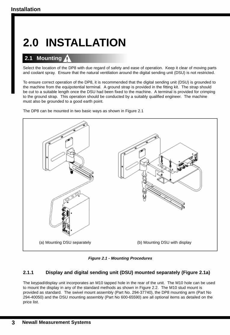
The DP8 can be mounted in two basic ways as shown in Figure 2.1
Figure 2.1 - Mounting Procedures
2.1.1 Display and digital sending unit (DSU) mounted separately (Figure 2.1a)
The keypad/display unit incorporates an M10 tapped hole in the rear of the unit. The M10 hole can be usedto mount the display in any of the standard methods as shown in Figure 2.2. The M10 stud mount isprovided as standard. The swivel mount assembly (Part No. 294-37740), the DP8 mounting arm (Part No294-40050) and the DSU mounting assembly (Part No 600-65590) are all optional items as detailed on theprice list.
(a) Mounting DSU separately (b) Mounting DSU with display
2.1 Mounting
Installation
Newall Measurement Systems 4
INS
TAL
LA
TIO
N
The DSU is normally mounted on a vertical face on the rear of the machine. The DSU facilitates the fixing in2, 3 or 4 point location. For metric applications drill and tap an M6 hole and locate the DSU by inserting oneof the M6 bolts provided. Ensure the DSU is level, mark the next location and drill and tap the second hole.Repeat this process for the required number of fixing locations. For those customers requiring imperial(Inch) fittings, repeat the above process substituting 1/4 inch UNC tapped hole and bolts.
Note: The fitting kit includes both the metric and imperial fittings. The metric fittings are zinc coated whereas the imperial fittings are black
The DSU is connected to the keypad/display via a 3.5 metre 9 pin “D” type cable. The cable can only beconnected in one direction. Once connected, secure the cable at both ends using the slotted lockingscrews.
Please note, as shown in Figure 2.1, the transducer and mains leads should be positioned underneath theDSU to avoid any ingress of coolant.
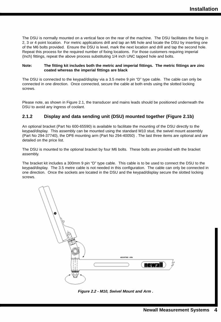
2.1.2 Display and data sending unit (DSU) mounted together (Figure 2.1b)
An optional bracket (Part No 600-65590) is available to facilitate the mounting of the DSU directly to thekeypad/display. This assembly can be mounted using the standard M10 stud, the swivel mount assembly(Part No 294-37740), the DP8 mounting arm (Part No 294-40050) . The last three items are optional and aredetailed on the price list.
The DSU is mounted to the optional bracket by four M6 bolts. These bolts are provided with the bracketassembly.
The bracket kit includes a 300mm 9 pin “D” type cable. This cable is to be used to connect the DSU to thekeypad/display. The 3.5 metre cable is not needed in this configuration. The cable can only be connected inone direction. Once the sockets are located in the DSU and the keypad/display secure the slotted lockingscrews.
Figure 2.2 - M10, Swivel Mount and Arm .
Installation
Newall Measurement Systems5
INS
TAL
LA
TIO
N
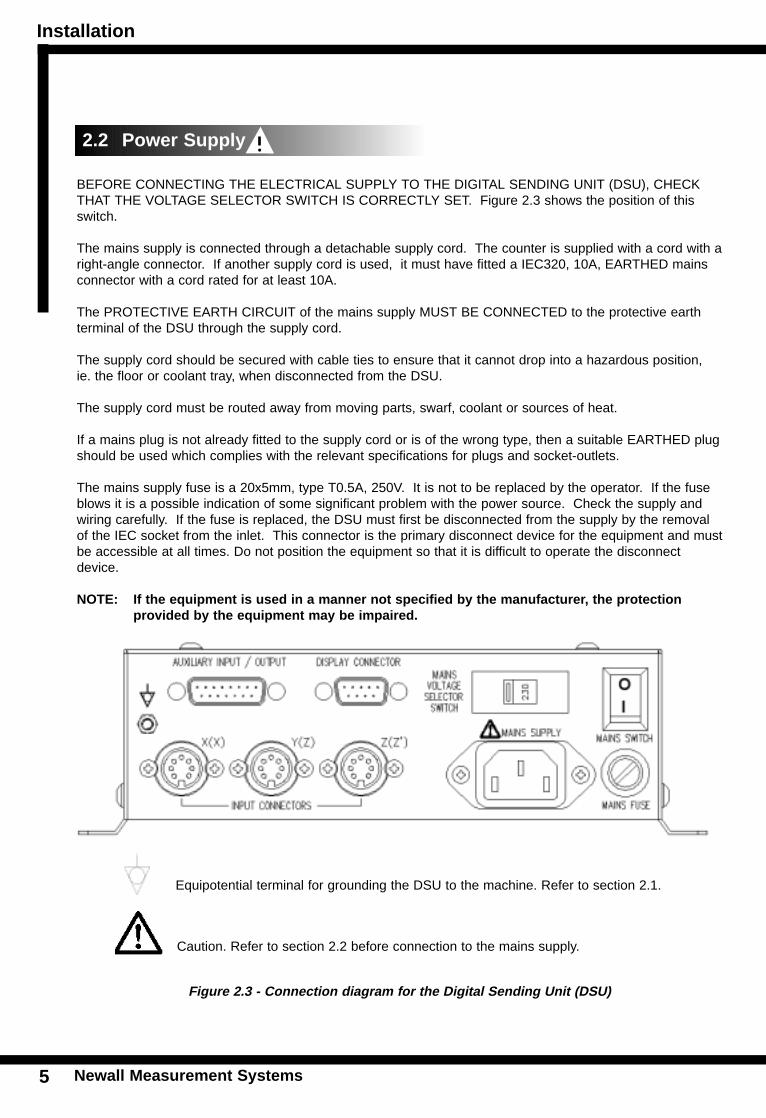
BEFORE CONNECTING THE ELECTRICAL SUPPLY TO THE DIGITAL SENDING UNIT (DSU), CHECKTHAT THE VOLTAGE SELECTOR SWITCH IS CORRECTLY SET. Figure 2.3 shows the position of thisswitch.
The mains supply is connected through a detachable supply cord. The counter is supplied with a cord with aright-angle connector. If another supply cord is used, it must have fitted a IEC320, 10A, EARTHED mainsconnector with a cord rated for at least 10A.
The PROTECTIVE EARTH CIRCUIT of the mains supply MUST BE CONNECTED to the protective earthterminal of the DSU through the supply cord.
The supply cord should be secured with cable ties to ensure that it cannot drop into a hazardous position,ie. the floor or coolant tray, when disconnected from the DSU.
The supply cord must be routed away from moving parts, swarf, coolant or sources of heat.
If a mains plug is not already fitted to the supply cord or is of the wrong type, then a suitable EARTHED plugshould be used which complies with the relevant specifications for plugs and socket-outlets.
The mains supply fuse is a 20x5mm, type T0.5A, 250V. It is not to be replaced by the operator. If the fuseblows it is a possible indication of some significant problem with the power source. Check the supply andwiring carefully. If the fuse is replaced, the DSU must first be disconnected from the supply by the removalof the IEC socket from the inlet. This connector is the primary disconnect device for the equipment and mustbe accessible at all times. Do not position the equipment so that it is difficult to operate the disconnectdevice.
NOTE: If the equipment is used in a manner not specified by the manufacturer, the protection provided by the equipment may be impaired.
Figure 2.3 - Connection diagram for the Digital Sending Unit (DSU)
2.2 Power Supply
Equipotential terminal for grounding the DSU to the machine. Refer to section 2.1.
Caution. Refer to section 2.2 before connection to the mains supply.
Installation
Newall Measurement Systems 6
The mains supply switch for the DP8 is mounted on the side of the DSU as shown in Figure 2.3.
When you switch on the DP8, the unit will automatically go through a brief self diagnostic routine.
During this routine, the name DP8 will be shown, then the software version number will be displayed and allsegments of the displays will be lit.
After this routine, the unit will display measurements and is ready for use.
The DP8 can be switched off via the mains switch on the DSU. Alternatively, the keypad/display can be switched off by pressing the key. Please note that the DSU remains under power when thekey is pressed.
Figure 2.3 shows the connection sockets on the DSU. The DP8 is designed for use with Newall’sSpherosyn and Microsyn transducers only. The transducers are connected to the DSU with Bleecon typeconnectors. These connectors have a sliding sleeve that locks the connectors to their sockets.
Switch off the DSU before connecting or disconnecting the transducers. To fit the connectors into theappropriate socket on the DSU, first align the connector and then push firmly in place. You should hear aclick confirming that the locking sleeve has engaged. To remove the connector, pull back on the connectorsleeve to disengage the locking mechanism.
The transducers and the display/keyboard are connected to the DSU at a separated extra low voltage(SELV) level. Any additional interconnections must also be at SELV level.
CONVENTIONS USED IN THIS MANUALThe direction of travel of an axis refers to the travel of the tool relative to the workpiece.
Keys on the keypad are signified in bold print, such as [ ENT ] for the enter key.
2.3 Transducer Connection
2.4 Switching On
User Instructions
Newall Measurement Systems7
Standard Keys Purpose
3.0 USER INSTRUCTIONS
The DP8 is available in three models, the DP8 Mill, DP8 Lathe and the DP8 EDM. Each DP8 model is avail-able with an optional auxiliary port. The auxiliary port is used for (i) a remote zero pendant (part number 600-17690) and (ii) for positional output data
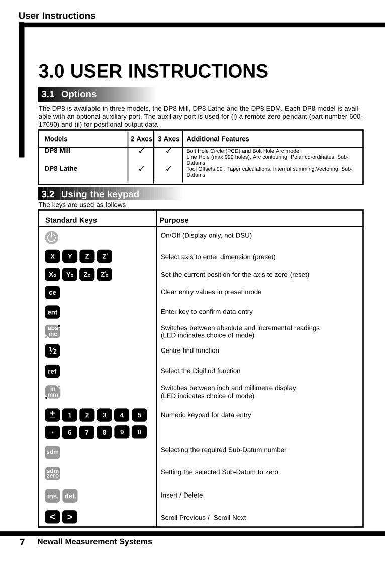
The keys are used as follows
Models 2 Axes 3 Axes Additional Features
DP8 Mill ✓ ✓ Bolt Hole Circle (PCD) and Bolt Hole Arc mode, Line Hole (max 999 holes), Arc contouring, Polar co-ordinates, Sub-Datums
DP8 Lathe ✓ ✓ Tool Offsets,99 , Taper calculations, Internal summing,Vectoring, Sub-Datums
On/Off (Display only, not DSU)
Select axis to enter dimension (preset)
Set the current position for the axis to zero (reset)
Clear entry values in preset mode
Enter key to confirm data entry
Switches between absolute and incremental readings(LED indicates choice of mode)
Centre find function
Select the Digifind function
Switches between inch and millimetre display (LED indicates choice of mode)
Numeric keypad for data entry
Selecting the required Sub-Datum number
Setting the selected Sub-Datum to zero
Insert / Delete
Scroll Previous / Scroll Next
X Y Z Z
Xo Yo Zo Zo
absinc
ce
1 2
ent
ref
inmm
1 2 3 4 5
6 7 8 9 0.+_
sdm
sdmzero
del.ins.
< >
3.2 Using the keypad
3.1 Options
User Instructions
Newall Measurement Systems 8
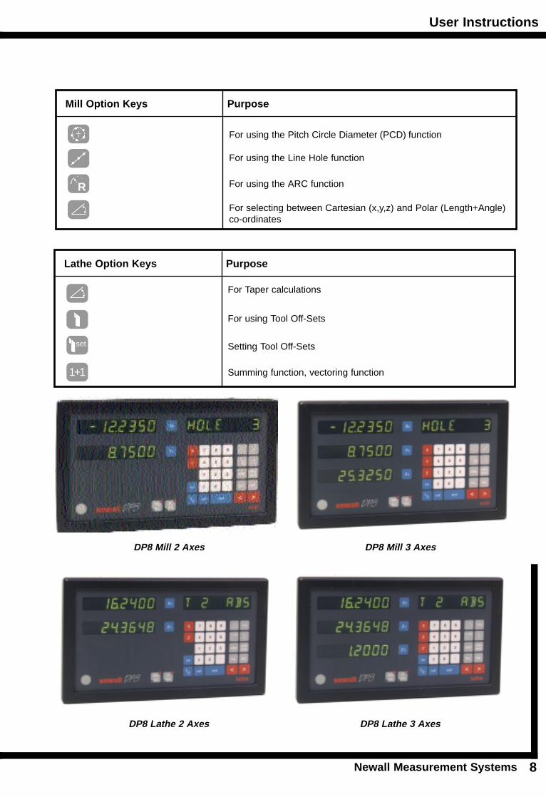
Mill Option Keys Purpose
For using the Pitch Circle Diameter (PCD) function
For using the Line Hole function
For using the ARC function
For selecting between Cartesian (x,y,z) and Polar (Length+Angle) co-ordinates
Lathe Option Keys Purpose
For Taper calculations
For using Tool Off-Sets
Setting Tool Off-Sets
Summing function, vectoring function
R
set
1+1
DP8 Mill 2 Axes DP8 Mill 3 Axes
DP8 Lathe 2 Axes DP8 Lathe 3 Axes
Set-Up
Newall Measurement Systems9
absinc
4.0 SET-UP
The DP8 digital readout display is equipped with a Set-Up Routine. The routine enables the operator tochange factory settings in order to increase efficiency and productivity. If the factory defaults are suitable,select the NORMAL option at the end of the Routine to restore the factory defaults.
Generally, the entire Set-Up Routine is performed only one time. Changing some parameters in Set-Up mayalter datums, SDMs, tool compensations and Digifind.
DO NOT RUN SET-UP IF YOU ARE NOT PREPARED TO LOSE THIS DATA.
Set-Up is enabled while the unit is running its initial self-test, just after powering on. Press the [ ON/OFF ] onthe face of the display as the self-test is running.
The Set-Up procedure makes use of a menu system. The main menu consists of a list of options that can becustomised for your use (See Table 1). You simply press the [ << ] and [ >> ] keys to scroll through this listuntil you reach the option you wish to change. To change the option when selected, press [ ENT].
To exit the Set-Up routine scroll through to the quit option and press [ENT ].
If the keypad/display has been switched off by pressing the [ ON/OFF ] key rather than switching off at the mains, it is possible to enter the Set-Up routine by pressing the [ ABS/INC ] key followed by the [ ON/OFF ]key.
ON/OFF key
ABS/INC key
ON/OFF key This is required to complete the proper sequence as described in text above
4.1 Set-Up Introduction
Set-U
p
New
all Measu
remen
t System
s10
Table 1 - Set-U
p Defaults
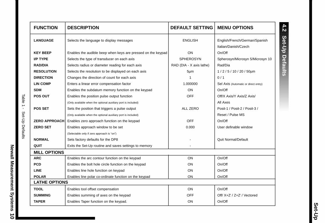
FUNCTION DESCRIPTION DEFAULT SETTING MENU OPTIONS
LANGUAGE Selects the language to display messages ENGLISH English/French/German/Spanish
Italian/Danish/Czech
KEY BEEP Enables the audible beep when keys are pressed on the keypad ON On/Off
I/P TYPE Selects the type of transducer on each axis SPHEROSYN Spherosyn/Microsyn 5/Microsyn 10
RAD/DIA Selects radius or diameter reading for each axis RAD (DIA - X axis lathe) Rad/Dia
RESOLUTION Selects the resolution to be displayed on each axis 5µm 1 / 2 / 5 / 10 / 20 / 50µm
DIRECTION Changes the direction of count for each axis 1 0 / 1
LIN COMP Enters a linear error compensation factor 1.000000 Sel Axis (Automatic or direct entry)
SDM Enables the subdatum memory function on the keypad ON On/Off
POS OUT Enables the position pulse output function OFF Off/X Axis/Y Axis/Z Axis/
(Only available when the optional auxiliary port is included) All Axes
POS SET Sets the position that triggers a pulse output ALL ZERO Posit-1 / Posit-2 / Posit-3 /
(Only available when the optional auxiliary port is included) Reset / Pulse MS
ZERO APPROACH Enables zero approach function on the keypad OFF On/Off
ZERO SET Enables approach window to be set 0.000 User definable window
(Selectable only if zero approach is “on”)
NORMAL Sets factory defaults for the DP8 - Quit Normal/Default
QUIT Exits the Set-Up routine and saves settings to memory -
MILL OPTIONSARC Enables the arc contour function on the keypad ON On/Off
PCD Enables the bolt hole circle function on the keypad ON On/Off
LINE Enables line hole function on keypad ON On/Off
POLAR Enables line polar co-ordinate function on the keypad ON On/Off
LATHE OPTIONS
TOOL Enables tool offset compensation ON On/Off
SUMMING Enables summing of axes on the keypad OFF Off/ X+Zl / Z+Zl / Vectored
TAPER Enables Taper function on the keypad. ON On/Off
4.2 S
et-Up
Defau
lts
Set-Up
Newall Measurement Systems11
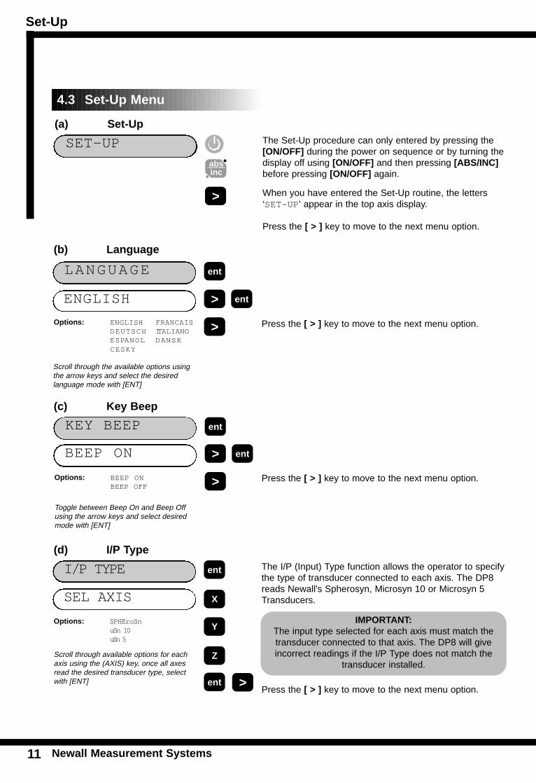
The I/P (Input) Type function allows the operator to specifythe type of transducer connected to each axis. The DP8reads Newall's Spherosyn, Microsyn 10 or Microsyn 5Transducers. SEL AXIS
Options: SPHEroSn uSn 10 uSn 5
entI/P TYPE
ent
Scroll through available options for eachaxis using the (AXIS) key, once all axesread the desired transducer type, selectwith [ENT]
X
Y
Z
>
IMPORTANT: The input type selected for each axis must match thetransducer connected to that axis. The DP8 will giveincorrect readings if the I/P Type does not match the
transducer installed.
(d) I/P Type
The Set-Up procedure can only entered by pressing the[ON/OFF] during the power on sequence or by turning thedisplay off using [ON/OFF] and then pressing [ABS/INC]before pressing [ON/OFF] again.
When you have entered the Set-Up routine, the letters‘SET-UP’ appear in the top axis display.
Press the [ > ] key to move to the next menu option.
SET-UPabsinc
>
ENGLISH
Options: ENGLISH FRANCAISDEUTSCH ITALIANOESPANOL DANSKCESKY
entLANGUAGE
BEEP ON >
Options: BEEP ONBEEP OFF
entKEY BEEP
ent
>
Scroll through the available options usingthe arrow keys and select the desired language mode with [ENT]
Toggle between Beep On and Beep Offusing the arrow keys and select desiredmode with [ENT]
> ent
>
(a) Set-Up
(b) Language
(c) Key Beep
4.3 Set-Up Menu
Press the [ > ] key to move to the next menu option.
Press the [ > ] key to move to the next menu option.
Press the [ > ] key to move to the next menu option.
Set-Up
Newall Measurement Systems 12
ET
UP
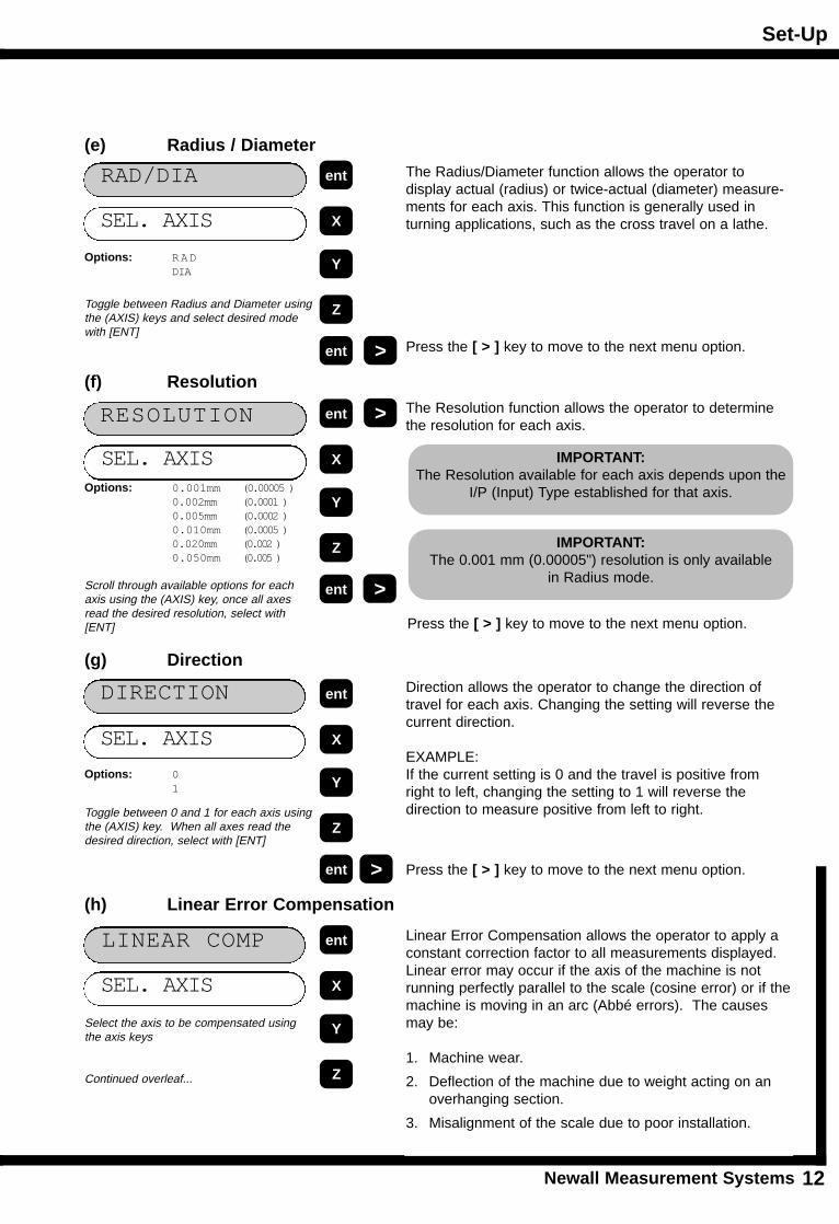
The Radius/Diameter function allows the operator to display actual (radius) or twice-actual (diameter) measure-ments for each axis. This function is generally used in turning applications, such as the cross travel on a lathe. SEL. AXIS
Options: RADDIA
RAD/DIA
The Resolution function allows the operator to determinethe resolution for each axis.
SEL. AXISOptions: 0.001mm (0.00005 )
0.002mm (0.0001 )0.005mm (0.0002 )0.010mm (0.0005 )0.020mm (0.002 )0.050mm (0.005 )
RESOLUTION
Toggle between Radius and Diameter usingthe (AXIS) keys and select desired modewith [ENT]
Scroll through available options for eachaxis using the (AXIS) key, once all axesread the desired resolution, select with[ENT]
ent
ent
X
Y
Z
>
ent
ent
X
Y
Z
>
Direction allows the operator to change the direction oftravel for each axis. Changing the setting will reverse thecurrent direction.
EXAMPLE:If the current setting is 0 and the travel is positive fromright to left, changing the setting to 1 will reverse the direction to measure positive from left to right.
SEL. AXIS
Options: 01
entDIRECTION
ent
Toggle between 0 and 1 for each axis usingthe (AXIS) key. When all axes read thedesired direction, select with [ENT]
X
Y
Z
>
IMPORTANT: The Resolution available for each axis depends upon the
I/P (Input) Type established for that axis.
IMPORTANT: The 0.001 mm (0.00005") resolution is only available
in Radius mode.
(e) Radius / Diameter
(f) Resolution
(g) Direction
Press the [ > ] key to move to the next menu option.
Press the [ > ] key to move to the next menu option.
>
Press the [ > ] key to move to the next menu option.
Linear Error Compensation allows the operator to apply aconstant correction factor to all measurements displayed.Linear error may occur if the axis of the machine is not running perfectly parallel to the scale (cosine error) or if themachine is moving in an arc (Abbé errors). The causesmay be:
1. Machine wear.
2. Deflection of the machine due to weight acting on an overhanging section.
3. Misalignment of the scale due to poor installation.
SEL. AXIS
LINEAR COMP
Select the axis to be compensated usingthe axis keys
Continued overleaf...
ent
X
Y
Z
(h) Linear Error Compensation
Set-Up
Newall Measurement Systems13
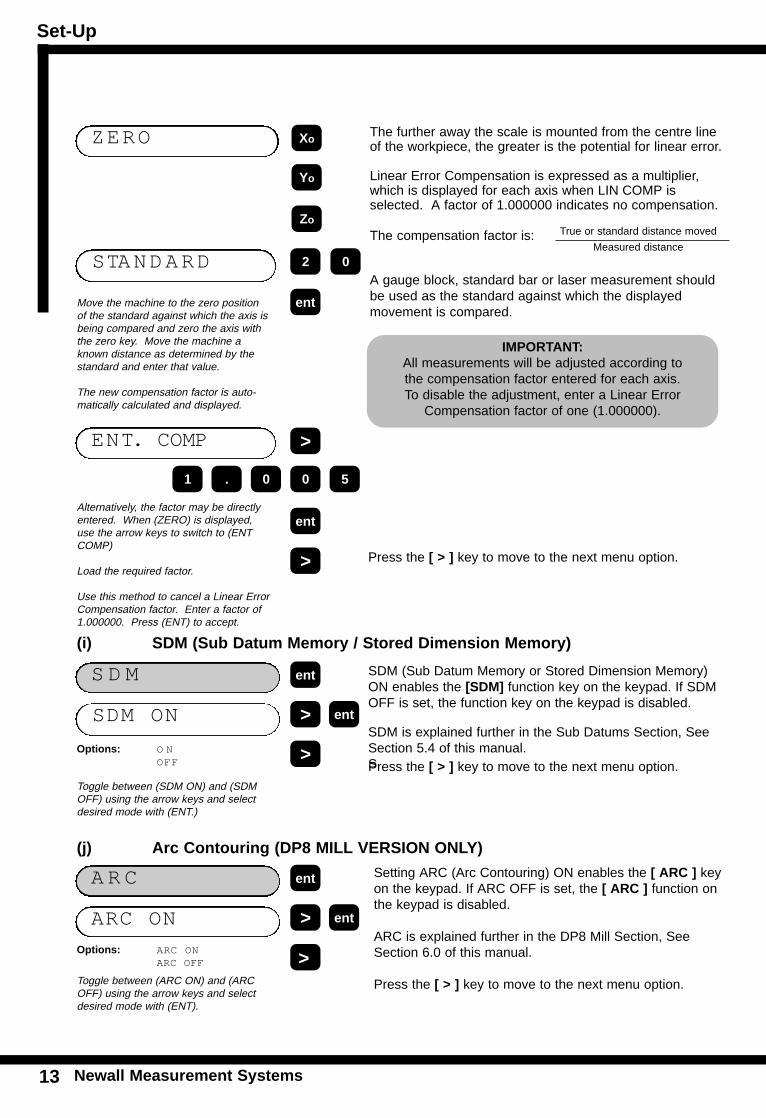
Setting ARC (Arc Contouring) ON enables the [ ARC ] keyon the keypad. If ARC OFF is set, the [ ARC ] function onthe keypad is disabled.
ARC is explained further in the DP8 Mill Section, SeeSection 6.0 of this manual.
Press the [ > ] key to move to the next menu option.
ARC ON
Options: ARC ONARC OFF
A R C
Toggle between (ARC ON) and (ARCOFF) using the arrow keys and selectdesired mode with (ENT).
ent
> ent
>
(j) Arc Contouring (DP8 MILL VERSION ONLY)
SDM (Sub Datum Memory or Stored Dimension Memory)ON enables the [SDM] function key on the keypad. If SDMOFF is set, the function key on the keypad is disabled.
SDM is explained further in the Sub Datums Section, SeeSection 5.4 of this manual.SPress the [ > ] key to move to the next menu option.
SDM ON
Options: O NOFF
S D M
Toggle between (SDM ON) and (SDMOFF) using the arrow keys and selectdesired mode with (ENT.)
ent
> ent
>
The further away the scale is mounted from the centre lineof the workpiece, the greater is the potential for linear error.
Linear Error Compensation is expressed as a multiplier,which is displayed for each axis when LIN COMP is selected. A factor of 1.000000 indicates no compensation.
True or standard distance movedThe compensation factor is:Measured distance
A gauge block, standard bar or laser measurement shouldbe used as the standard against which the displayed movement is compared.
ZERO
Move the machine to the zero positionof the standard against which the axis isbeing compared and zero the axis withthe zero key. Move the machine aknown distance as determined by thestandard and enter that value.
The new compensation factor is auto-matically calculated and displayed.
ent
Xo
Yo
Zo
>
IMPORTANT: All measurements will be adjusted according to the compensation factor entered for each axis. To disable the adjustment, enter a Linear Error
Compensation factor of one (1.000000).
(i) SDM (Sub Datum Memory / Stored Dimension Memory)
Press the [ > ] key to move to the next menu option.
STANDARD 2 0
Alternatively, the factor may be directlyentered. When (ZERO) is displayed,use the arrow keys to switch to (ENTCOMP)
Load the required factor.
Use this method to cancel a Linear ErrorCompensation factor. Enter a factor of1.000000. Press (ENT) to accept.
ent
ENT. COMP
0 5
>
. 01
Set-Up
Newall Measurement Systems 14
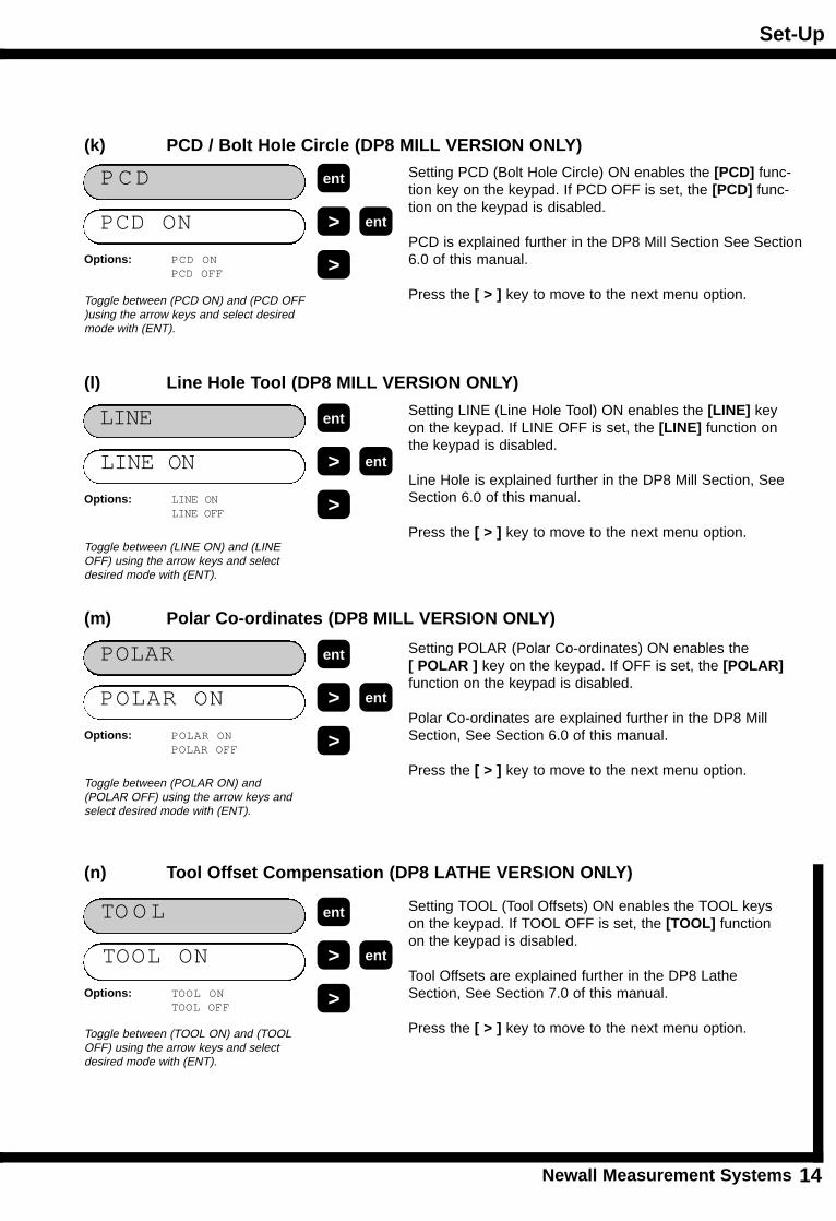
Setting PCD (Bolt Hole Circle) ON enables the [PCD] func-tion key on the keypad. If PCD OFF is set, the [PCD] func-tion on the keypad is disabled.
PCD is explained further in the DP8 Mill Section See Section6.0 of this manual.
Press the [ > ] key to move to the next menu option.
PCD ON
Options: PCD ONPCD OFF
PCD
Toggle between (PCD ON) and (PCD OFF)using the arrow keys and select desiredmode with (ENT).
ent
> ent
>
Setting LINE (Line Hole Tool) ON enables the [LINE] keyon the keypad. If LINE OFF is set, the [LINE] function onthe keypad is disabled.
Line Hole is explained further in the DP8 Mill Section, SeeSection 6.0 of this manual.
Press the [ > ] key to move to the next menu option.
LINE ON
Options: LINE ONLINE OFF
LINE
Toggle between (LINE ON) and (LINEOFF) using the arrow keys and selectdesired mode with (ENT).
ent
> ent
>
Setting POLAR (Polar Co-ordinates) ON enables the[ POLAR ] key on the keypad. If OFF is set, the [POLAR] function on the keypad is disabled.
Polar Co-ordinates are explained further in the DP8 MillSection, See Section 6.0 of this manual.
Press the [ > ] key to move to the next menu option.
POLAR ON
Options: POLAR ONPOLAR OFF
POLAR
Toggle between (POLAR ON) and(POLAR OFF) using the arrow keys andselect desired mode with (ENT).
ent
> ent
>
(k) PCD / Bolt Hole Circle (DP8 MILL VERSION ONLY)
(l) Line Hole Tool (DP8 MILL VERSION ONLY)
(m) Polar Co-ordinates (DP8 MILL VERSION ONLY)
Setting TOOL (Tool Offsets) ON enables the TOOL keyson the keypad. If TOOL OFF is set, the [TOOL] functionon the keypad is disabled.
Tool Offsets are explained further in the DP8 LatheSection, See Section 7.0 of this manual.
Press the [ > ] key to move to the next menu option.
TOOL ON
Options: TOOL ONTOOL OFF
TO O L
Toggle between (TOOL ON) and (TOOLOFF) using the arrow keys and selectdesired mode with (ENT).
ent
> ent
>
(n) Tool Offset Compensation (DP8 LATHE VERSION ONLY)
Set-Up
Newall Measurement Systems15
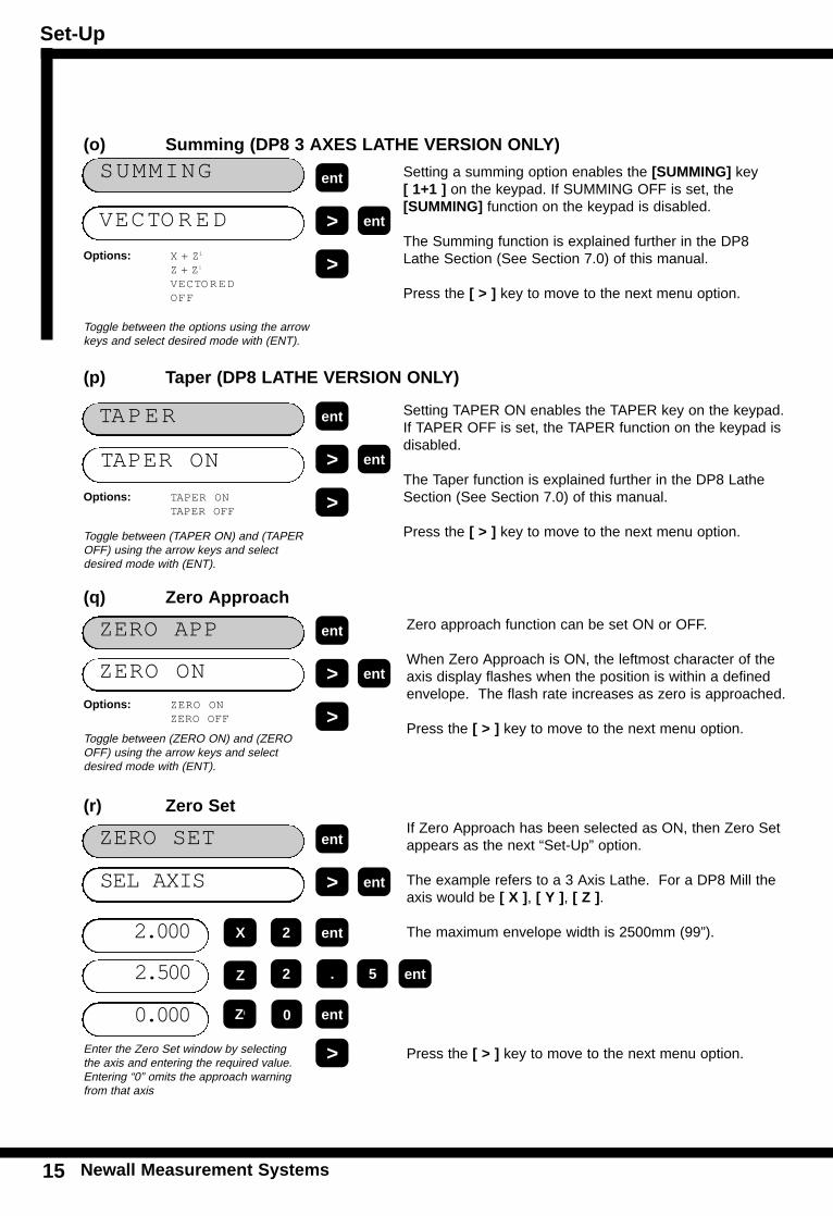
Zero approach function can be set ON or OFF.
When Zero Approach is ON, the leftmost character of theaxis display flashes when the position is within a definedenvelope. The flash rate increases as zero is approached.
Press the [ > ] key to move to the next menu option.
ZERO ON
Options: ZERO ONZERO OFF
ZERO APP
Toggle between (ZERO ON) and (ZEROOFF) using the arrow keys and selectdesired mode with (ENT).
ent
> ent
>
Setting a summing option enables the [SUMMING] key [ 1+1 ] on the keypad. If SUMMING OFF is set, the [SUMMING] function on the keypad is disabled.
The Summing function is explained further in the DP8Lathe Section (See Section 7.0) of this manual.
Press the [ > ] key to move to the next menu option.
VECTORED
Options: X + Zi
Z + Zi
VECTOREDOFF
SUMMING
Toggle between the options using the arrowkeys and select desired mode with (ENT).
ent
> ent
>
Setting TAPER ON enables the TAPER key on the keypad.If TAPER OFF is set, the TAPER function on the keypad isdisabled.
The Taper function is explained further in the DP8 LatheSection (See Section 7.0) of this manual.
Press the [ > ] key to move to the next menu option.
TAPER ON
Options: TAPER ONTAPER OFF
TAPER
Toggle between (TAPER ON) and (TAPEROFF) using the arrow keys and selectdesired mode with (ENT).
ent
> ent
>
(o) Summing (DP8 3 AXES LATHE VERSION ONLY)
(p) Taper (DP8 LATHE VERSION ONLY)
(q) Zero Approach
If Zero Approach has been selected as ON, then Zero Setappears as the next “Set-Up” option.
The example refers to a 3 Axis Lathe. For a DP8 Mill theaxis would be [ X ], [ Y ], [ Z ].
The maximum envelope width is 2500mm (99”).
Press the [ > ] key to move to the next menu option.
SEL AXIS
ZERO SET
Enter the Zero Set window by selectingthe axis and entering the required value.Entering “0” omits the approach warningfrom that axis
ent
> ent
>
(r) Zero Set
2.000
2.500
0.000
X
Z
Zl
2 ent
ent2
ent0
. 5
Set-Up
Newall Measurement Systems 16
SE
TU
P
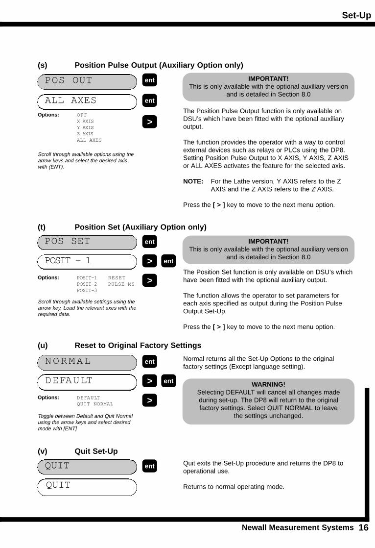
Normal returns all the Set-Up Options to the original factory settings (Except language setting).
DEFAULT
Options: DEFAULTQUIT NORMAL
N ORMAL
Toggle between Default and Quit Normalusing the arrow keys and select desiredmode with [ENT]
ent
> ent
>
WARNING!Selecting DEFAULT will cancel all changes made during set-up. The DP8 will return to the original factory settings. Select QUIT NORMAL to leave
the settings unchanged.
Quit exits the Set-Up procedure and returns the DP8 tooperational use.
Returns to normal operating mode.QUIT
QUIT ent
The Position Set function is only available on DSU’s whichhave been fitted with the optional auxiliary output.
The function allows the operator to set parameters foreach axis specified as output during the Position PulseOutput Set-Up.
Press the [ > ] key to move to the next menu option.
POSIT - 1
Options: POSIT-1 RESETPOSIT-2 PULSE MSPOSIT-3
POS SET
Scroll through available settings using thearrow key, Load the relevant axes with therequired data.
ent
> ent
>
The Position Pulse Output function is only available onDSU’s which have been fitted with the optional auxiliaryoutput.
The function provides the operator with a way to controlexternal devices such as relays or PLCs using the DP8. Setting Position Pulse Output to X AXIS, Y AXIS, Z AXISor ALL AXES activates the feature for the selected axis.
NOTE: For the Lathe version, Y AXIS refers to the Z AXIS and the Z AXIS refers to the Zl AXIS.
Press the [ > ] key to move to the next menu option.
ALL AXESOptions: OFF
X AXISY AXISZ AXISALL AXES
POS OUT
Scroll through available options using thearrow keys and select the desired axiswith (ENT).
ent
ent
>
(s) Position Pulse Output (Auxiliary Option only)
(t) Position Set (Auxiliary Option only)
(u) Reset to Original Factory Settings
(v) Quit Set-Up
IMPORTANT!This is only available with the optional auxiliary version
and is detailed in Section 8.0
IMPORTANT!This is only available with the optional auxiliary version
and is detailed in Section 8.0
Standard Functions
Newall Measurement Systems17
STA
ND
AR
D F
UN
CT
ION
S
5.0 STANDARD FUNCTIONS
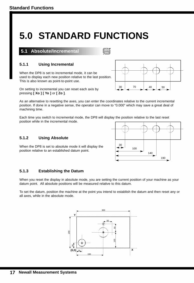
5.1.1 Using Incremental
When the DP8 is set to incremental mode, it can be used to display each new position relative to the last position. This is also known as point-to-point use.
On setting to incremental you can reset each axis by pressing [ Xo ] [ Yo ] or [ Zo ].
As an alternative to resetting the axes, you can enter the coordinates relative to the current incrementalposition. If done in a negative sense, the operator can move to “0.000” which may save a great deal ofmachining time.
Each time you switch to incremental mode, the DP8 will display the position relative to the last reset position while in the incremental mode.
5.1.2 Using Absolute
When the DP8 is set to absolute mode it will display the position relative to an established datum point.
5.1.3 Establishing the Datum
When you reset the display in absolute mode, you are setting the current position of your machine as yourdatum point. All absolute positions will be measured relative to this datum.
To set the datum, position the machine at the point you intend to establish the datum and then reset any orall axes, while in the absolute mode.
A
B
C50
100
200
30
30
150
300
30 70 40 50
30100
140
190
5.1 Absolute/Incremental absinc
50
(0,0)
Y
X
Standard Functions
Newall Measurement Systems 18
STA
ND
AR
DF
UN
CT
ION
S
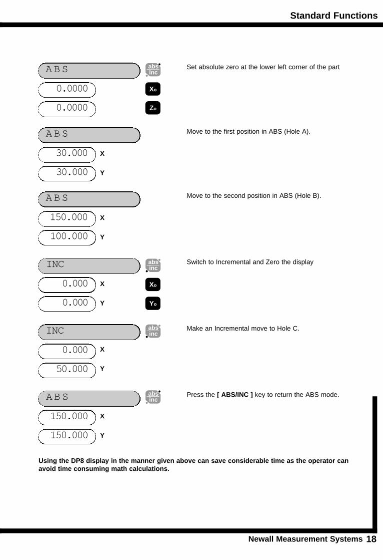
Set absolute zero at the lower left corner of the part
0.0000
ABS
0.0000
Xo
absinc
Zo
Move to the first position in ABS (Hole A).
30.000
ABS
30.000
Switch to Incremental and Zero the display
0.000
INC
0.000
Move to the second position in ABS (Hole B).
150.000
ABS
100.000
absinc
Make an Incremental move to Hole C.
0.000
INC
50.000
Press the [ ABS/INC ] key to return the ABS mode.
150.000
ABS
150.000
absinc
X
Y
Xo
Yo
X
Y
X
Y
X
Y
absinc
X
Y
Using the DP8 display in the manner given above can save considerable time as the operator canavoid time consuming math calculations.
Standard Functions
1 Newall Measurement Systems19
STA
ND
AR
D F
UN
CT
ION
S
ref
1 2
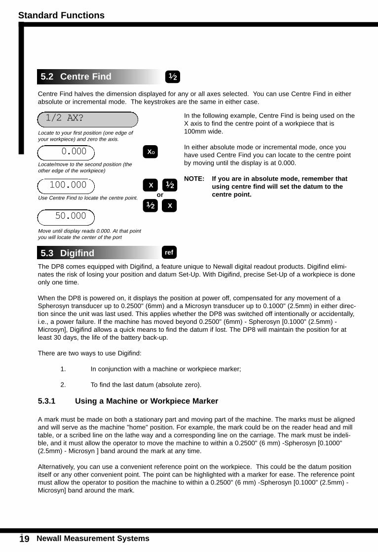
Centre Find halves the dimension displayed for any or all axes selected. You can use Centre Find in eitherabsolute or incremental mode. The keystrokes are the same in either case.
The DP8 comes equipped with Digifind, a feature unique to Newall digital readout products. Digifind elimi-nates the risk of losing your position and datum Set-Up. With Digifind, precise Set-Up of a workpiece is doneonly one time.
When the DP8 is powered on, it displays the position at power off, compensated for any movement of aSpherosyn transducer up to 0.2500" (6mm) and a Microsyn transducer up to 0.1000" (2.5mm) in either direc-tion since the unit was last used. This applies whether the DP8 was switched off intentionally or accidentally,i.e., a power failure. If the machine has moved beyond 0.2500" (6mm) - Spherosyn [0.1000" (2.5mm) -Microsyn], Digifind allows a quick means to find the datum if lost. The DP8 will maintain the position for atleast 30 days, the life of the battery back-up.
There are two ways to use Digifind:
1. In conjunction with a machine or workpiece marker;
2. To find the last datum (absolute zero).
5.3.1 Using a Machine or Workpiece Marker
A mark must be made on both a stationary part and moving part of the machine. The marks must be alignedand will serve as the machine "home" position. For example, the mark could be on the reader head and milltable, or a scribed line on the lathe way and a corresponding line on the carriage. The mark must be indeli-ble, and it must allow the operator to move the machine to within a 0.2500" (6 mm) -Spherosyn [0.1000"(2.5mm) - Microsyn ] band around the mark at any time.
Alternatively, you can use a convenient reference point on the workpiece. This could be the datum positionitself or any other convenient point. The point can be highlighted with a marker for ease. The reference pointmust allow the operator to position the machine to within a 0.2500" (6 mm) -Spherosyn [0.1000" (2.5mm) -Microsyn] band around the mark.
In the following example, Centre Find is being used on theX axis to find the centre point of a workpiece that is100mm wide.
In either absolute mode or incremental mode, once youhave used Centre Find you can locate to the centre pointby moving until the display is at 0.000.
NOTE: If you are in absolute mode, remember that using centre find will set the datum to the centre point.
0.000
1/2 AX?
100.000
Locate to your first position (one edge ofyour workpiece) and zero the axis.
XO
X 1 2or
X1 2Use Centre Find to locate the centre point.
Locate/move to the second position (theother edge of the workpiece)
50.000
5.3 Digifind
5.2 Centre Find
Move until display reads 0.000. At that pointyou will locate the center of the port
Standard Functions
Newall Measurement Systems 20
STA
ND
AR
DF
UN
CT
ION
S
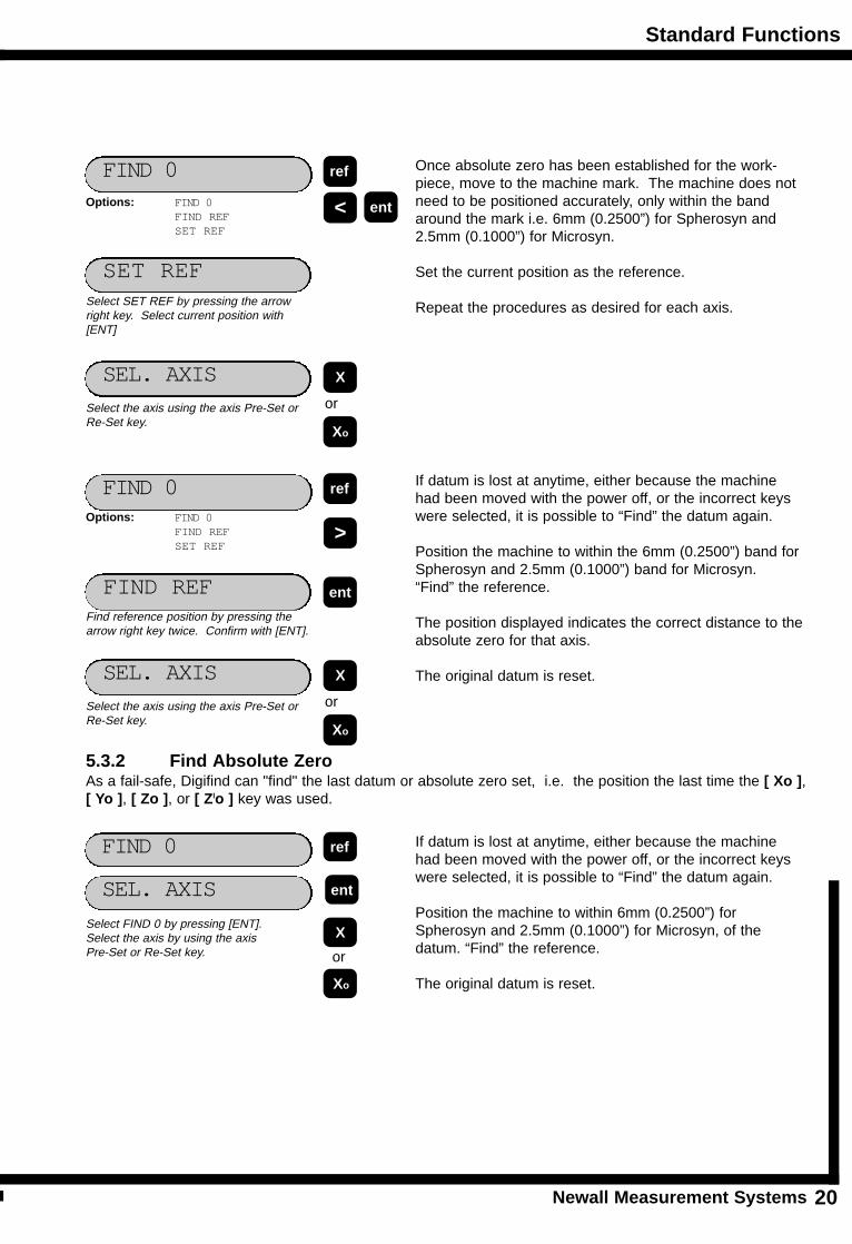
Once absolute zero has been established for the work-piece, move to the machine mark. The machine does notneed to be positioned accurately, only within the bandaround the mark i.e. 6mm (0.2500”) for Spherosyn and2.5mm (0.1000”) for Microsyn.
Set the current position as the reference.
Repeat the procedures as desired for each axis.
SET REF
FIND 0
If datum is lost at anytime, either because the machinehad been moved with the power off, or the incorrect keyswere selected, it is possible to “Find” the datum again.
Position the machine to within the 6mm (0.2500”) band forSpherosyn and 2.5mm (0.1000”) band for Microsyn.“Find” the reference.
The position displayed indicates the correct distance to theabsolute zero for that axis.
The original datum is reset.
FIND REF
FIND 0
<
Select SET REF by pressing the arrowright key. Select current position with[ENT]
Find reference position by pressing thearrow right key twice. Confirm with [ENT].
ref
ent
>
ref
Options: FIND 0FIND REFSET REF
SEL. AXISSelect the axis using the axis Pre-Set orRe-Set key.
X
Xo
or
Options: FIND 0FIND REFSET REF
SEL. AXISSelect the axis using the axis Pre-Set orRe-Set key.
X
Xo
or
5.3.2 Find Absolute Zero As a fail-safe, Digifind can "find" the last datum or absolute zero set, i.e. the position the last time the [ Xo ],[ Yo ], [ Zo ], or [ Zlo ] key was used.
If datum is lost at anytime, either because the machinehad been moved with the power off, or the incorrect keyswere selected, it is possible to “Find” the datum again.
Position the machine to within 6mm (0.2500”) forSpherosyn and 2.5mm (0.1000”) for Microsyn, of thedatum. “Find” the reference.
The original datum is reset.
SEL. AXIS
FIND 0
Select FIND 0 by pressing [ENT].Select the axis by using the axis Pre-Set or Re-Set key.
ent
ref
X
Xo
or
ent
Standard Functions
Newall Measurement Systems21
STA
ND
AR
D F
UN
CT
ION
S
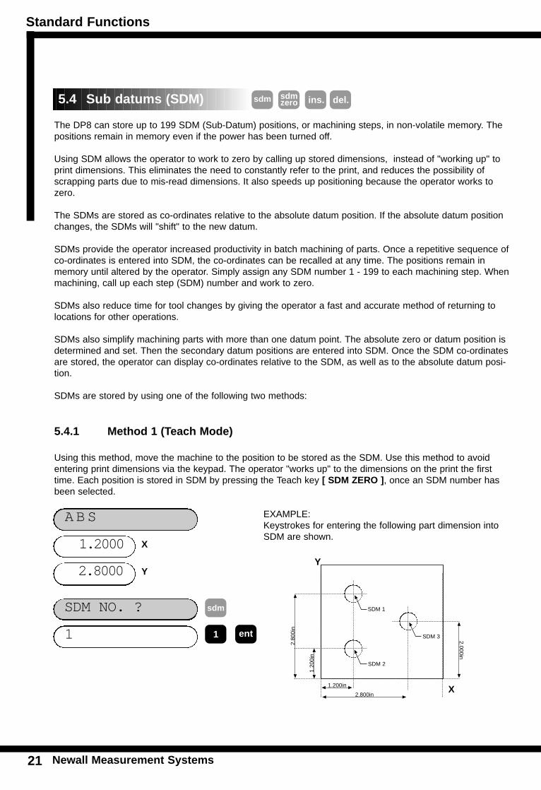
The DP8 can store up to 199 SDM (Sub-Datum) positions, or machining steps, in non-volatile memory. Thepositions remain in memory even if the power has been turned off.
Using SDM allows the operator to work to zero by calling up stored dimensions, instead of "working up" toprint dimensions. This eliminates the need to constantly refer to the print, and reduces the possibility ofscrapping parts due to mis-read dimensions. It also speeds up positioning because the operator works tozero.
The SDMs are stored as co-ordinates relative to the absolute datum position. If the absolute datum positionchanges, the SDMs will "shift" to the new datum.
SDMs provide the operator increased productivity in batch machining of parts. Once a repetitive sequence ofco-ordinates is entered into SDM, the co-ordinates can be recalled at any time. The positions remain inmemory until altered by the operator. Simply assign any SDM number 1 - 199 to each machining step. Whenmachining, call up each step (SDM) number and work to zero.
SDMs also reduce time for tool changes by giving the operator a fast and accurate method of returning tolocations for other operations.
SDMs also simplify machining parts with more than one datum point. The absolute zero or datum position isdetermined and set. Then the secondary datum positions are entered into SDM. Once the SDM co-ordinatesare stored, the operator can display co-ordinates relative to the SDM, as well as to the absolute datum posi-tion.
SDMs are stored by using one of the following two methods:
1
SDM NO. ?
1.2000
ABS
2.8000
sdm sdmzero
sdm
EXAMPLE: Keystrokes for entering the following part dimension intoSDM are shown.
ent1
SDM 1
SDM 2
SDM 3
2.800in
1.200in
1.20
0in
2.80
0in
2.000in
del.ins.
5.4.1 Method 1 (Teach Mode)
Using this method, move the machine to the position to be stored as the SDM. Use this method to avoidentering print dimensions via the keypad. The operator "works up" to the dimensions on the print the firsttime. Each position is stored in SDM by pressing the Teach key [ SDM ZERO ], once an SDM number hasbeen selected.
5.4 Sub datums (SDM)
X
YY
X
Standard Functions
Newall Measurement Systems 22
STA
ND
AR
DF
UN
CT
ION
S
0.0000
SDM 1
0.0000
sdmzero
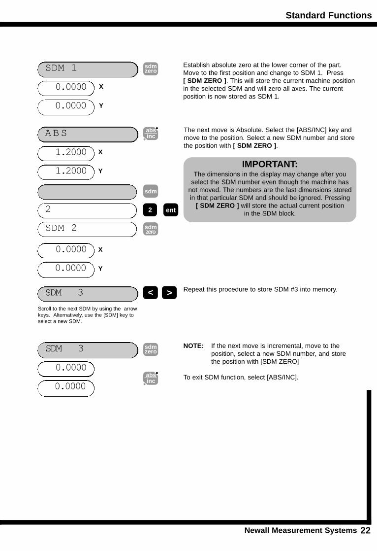
Establish absolute zero at the lower corner of the part.Move to the first position and change to SDM 1. Press [ SDM ZERO ]. This will store the current machine positionin the selected SDM and will zero all axes. The currentposition is now stored as SDM 1.
SDM 3
The next move is Absolute. Select the [ABS/INC] key andmove to the position. Select a new SDM number and storethe position with [ SDM ZERO ].
0.0000
SDM 3
0.0000
sdmzero
1.2000
ABS
1.2000
absinc
< >
Scroll to the next SDM by using the arrowkeys. Alternatively, use the [SDM] key toselect a new SDM.
IMPORTANT: The dimensions in the display may change after you
select the SDM number even though the machine hasnot moved. The numbers are the last dimensions storedin that particular SDM and should be ignored. Pressing
[ SDM ZERO ] will store the actual current positionin the SDM block.
absinc
Repeat this procedure to store SDM #3 into memory.
NOTE: If the next move is Incremental, move to the position, select a new SDM number, and store the position with [SDM ZERO]
To exit SDM function, select [ABS/INC].
2
SDM 2
sdm
2 ent
sdmzero
X
Y
X
Y
X
Y
0.0000
0.0000
Standard Functions
Newall Measurement Systems23
STA
ND
AR
D F
UN
CT
ION
S
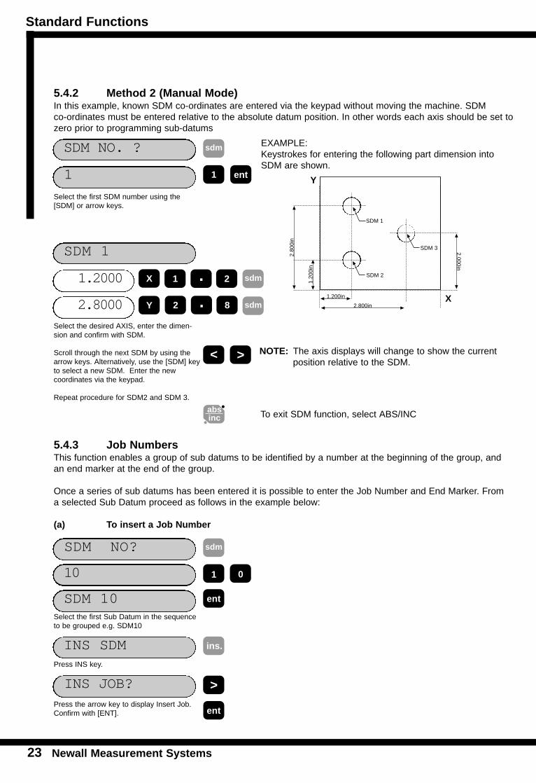
5.4.2 Method 2 (Manual Mode)In this example, known SDM co-ordinates are entered via the keypad without moving the machine. SDM co-ordinates must be entered relative to the absolute datum position. In other words each axis should be set tozero prior to programming sub-datums
1
SDM NO. ? sdm EXAMPLE: Keystrokes for entering the following part dimension intoSDM are shown.
ent1
1.2000
SDM 1
2.8000
1 2.
Select the first SDM number using the[SDM] or arrow keys.
Select the desired AXIS, enter the dimen-sion and confirm with SDM.
Scroll through the next SDM by using thearrow keys. Alternatively, use the [SDM] keyto select a new SDM. Enter the new coordinates via the keypad.
Repeat procedure for SDM2 and SDM 3.
2 8.
< >
To exit SDM function, select ABS/INC
5.4.3 Job Numbers This function enables a group of sub datums to be identified by a number at the beginning of the group, andan end marker at the end of the group.
Once a series of sub datums has been entered it is possible to enter the Job Number and End Marker. Froma selected Sub Datum proceed as follows in the example below:
(a) To insert a Job Number
SDM NO? sdm
ent
Select the first Sub Datum in the sequenceto be grouped e.g. SDM10
SDM 1
SDM 2
SDM 3
2.800in
1.200in
1.20
0in
2.80
0in
2.000in
absinc
INS SDMPress INS key.
>
ins.
1 0
INS JOB?
entPress the arrow key to display Insert Job.Confirm with [ENT].
10
SDM 10
sdm
sdm
NOTE: The axis displays will change to show the current position relative to the SDM.
X
Y
Y
X
Standard Functions
Newall Measurement Systems 24
STA
ND
AR
DF
UN
CT
ION
S
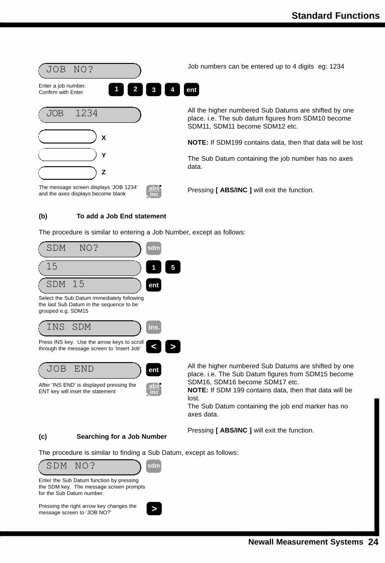
JOB NO? Job numbers can be entered up to 4 digits eg: 1234
entEnter a job number. Confirm with Enter
JOB 1234 All the higher numbered Sub Datums are shifted by oneplace. i.e. The sub datum figures from SDM10 becomeSDM11, SDM11 become SDM12 etc.
NOTE: If SDM199 contains data, then that data will be lost
The Sub Datum containing the job number has no axesdata.
The message screen displays 'JOB 1234'and the axes displays become blank
3 421
Pressing [ ABS/INC ] will exit the function.absinc
(b) To add a Job End statement
The procedure is similar to entering a Job Number, except as follows:
INS SDM
All the higher numbered Sub Datums are shifted by oneplace. i.e. The Sub Datum figures from SDM15 becomeSDM16, SDM16 become SDM17 etc.NOTE: If SDM 199 contains data, then that data will belost.The Sub Datum containing the job end marker has noaxes data.
Pressing [ ABS/INC ] will exit the function.
Press INS key. Use the arrow keys to scrollthrough the message screen to ‘Insert Job’
ins.
JOB END ent
After 'INS END' is displayed pressing theENT key will inset the statement
absinc
(c) Searching for a Job Number
The procedure is similar to finding a Sub Datum, except as follows:
SDM NO? sdm
Enter the Sub Datum function by pressingthe SDM key. The message screen promptsfor the Sub Datum number.
Pressing the right arrow key changes the message screen to ‘JOB NO?’ >
SDM NO? sdm
ent
Select the Sub Datum immediately followingthe last Sub Datum in the sequence to begrouped e.g. SDM15
1 515
SDM 15
< >
X
Z
Y
Standard Functions
Newall Measurement Systems25
JOB NO?
entEnter the required job number. Confirm with Enter
JOB 1234 The Sub Datums are searched to find the Job Number. If the number is not found the first number will be displayed.
3 421
Pressing [ ABS/INC ] at any time will exit the function.
ent
>Alternatively, the right arrow key will displayall the available job numbers.
Pressing the (ENT) key will make the selected job number active.
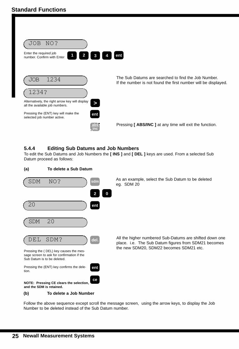
5.4.4 Editing Sub Datums and Job Numbers To edit the Sub Datums and Job Numbers the [ INS ] and [ DEL ] keys are used. From a selected SubDatum proceed as follows:
(a) To delete a Sub Datum
SDM 20
As an example, select the Sub Datum to be deleted eg. SDM 20
DEL SDM?
Pressing the ( DEL) key causes the mes-sage screen to ask for confirmation if theSub Datum is to be deleted.
Pressing the (ENT) key confirms the dele-tion.
NOTE: Pressing CE clears the selection,and the SDM is retained.
ent
del.
ce
(b) To delete a Job Number
Follow the above sequence except scroll the message screen, using the arrow keys, to display the JobNumber to be deleted instead of the Sub Datum number.
SDM NO? sdm
ent
2 0
20
absinc
1234?
All the higher numbered Sub-Datums are shifted down oneplace. i.e. The Sub Datum figures from SDM21 becomesthe new SDM20, SDM22 becomes SDM21 etc.
Standard Functions
Newall Measurement Systems 26
STA
ND
AR
DF
UN
CT
ION
S
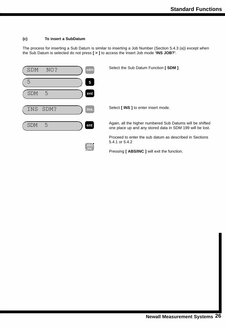
(c) To insert a SubDatum
The process for inserting a Sub Datum is similar to inserting a Job Number (Section 5.4.3 (a)) except whenthe Sub Datum is selected do not press [ > ] to access the Insert Job mode ‘INS JOB?’.
SDM NO? sdm Select the Sub Datum Function [ SDM ].
INS SDM?
Again, all the higher numbered Sub Datums will be shiftedone place up and any stored data in SDM 199 will be lost.
Proceed to enter the sub datum as described in Sections5.4.1 or 5.4.2
Pressing [ ABS/INC ] will exit the function.
ins.
absinc
Select [ INS ] to enter insert mode.
SDM 5 ent
55
SDM 5 ent
Standard Functions
Newall Measurement Systems27
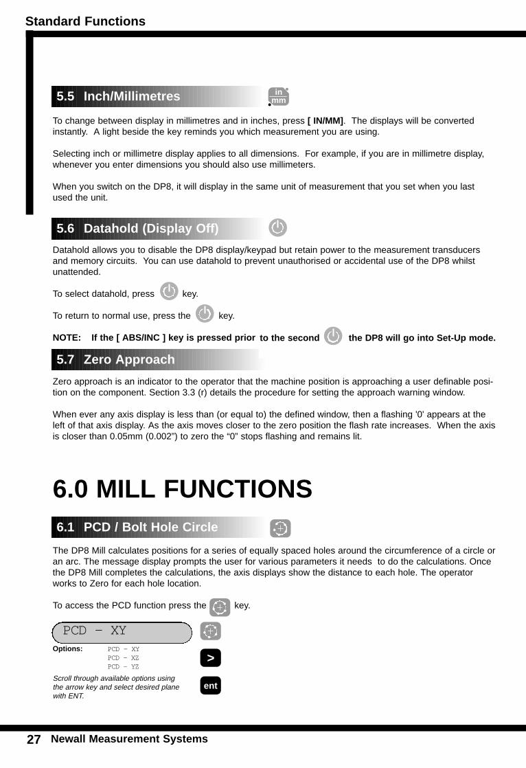
To change between display in millimetres and in inches, press [ IN/MM]. The displays will be convertedinstantly. A light beside the key reminds you which measurement you are using.
Selecting inch or millimetre display applies to all dimensions. For example, if you are in millimetre display,whenever you enter dimensions you should also use millimeters.
When you switch on the DP8, it will display in the same unit of measurement that you set when you lastused the unit.
Datahold allows you to disable the DP8 display/keypad but retain power to the measurement transducersand memory circuits. You can use datahold to prevent unauthorised or accidental use of the DP8 whilstunattended.
To select datahold, press key.
To return to normal use, press the key.
NOTE: If the [ ABS/INC ] key is pressed prior DP8 will go
Zero approach is an indicator to the operator that the machine position is approaching a user definable posi-tion on the component. Section 3.3 (r) details the procedure for setting the approach warning window.
When ever any axis display is less than (or equal to) the defined window, then a flashing '0' appears at theleft of that axis display. As the axis moves closer to the zero position the flash rate increases. When the axisis closer than 0.05mm (0.002”) to zero the “0” stops flashing and remains lit.
6.0 MILL FUNCTIONS
The DP8 Mill calculates positions for a series of equally spaced holes around the circumference of a circle oran arc. The message display prompts the user for various parameters it needs to do the calculations. Oncethe DP8 Mill completes the calculations, the axis displays show the distance to each hole. The operatorworks to Zero for each hole location.
To access the PCD function press the key.
6.1 PCD / Bolt Hole Circle
5.5 Inch/Millimetres
5.6 Datahold (Display Off)
5.7 Zero Approach
inmm
PCD - XYOptions: PCD - XY
PCD - XZPCD - YZ
>
entScroll through available options using the arrow key and select desired plane with ENT.
to the second the DP8 will go into Set-Up mode.
Mill Functions
Newall Measurement Systems 28
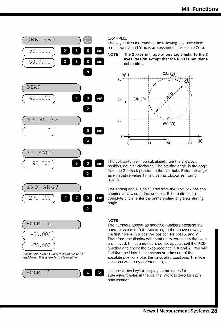
EXAMPLE: The keystrokes for entering the following bolt hole circleare shown. X and Y axes are assumed at Absolute Zero.
50.0000
CENTRE?
50.0000
X
Z
The bolt pattern will be calculated from the 3 o'clock position, counter-clockwise. The starting angle is the anglefrom the 3 o'clock position to the first hole. Enter the angleas a negative value if it is given as clockwise from 3o'clock.
The ending angle is calculated from the 3 o'clock positioncounter-clockwise to the last hole. If the pattern is a complete circle, enter the same ending angle as startingangle.
40.0000
DIA?
0 ent
>
3
NO HOLES
3 ent
>
90.000
ST ANG?
0 ent
>
270.000
END ANG?
7 ent
>
-50.000
HOLE 1
>
-70.000
9
2
Position the X and Y axes until both displaysread Zero. This is the first hole location.
HOLE 2 < > Use the arrow keys to display co-ordinates for subsequent holes in the routine. Work to zero for eachhole location.
X
Y
90 O
50
500
0
70
30
30 70
D 40.
0
(50,70)
(50,30)
(30,50)
NOTE: The 2 axes mill operations are similar to the 3axes version except that the PCD is not planeselectable.
0
ent
ent
5 0
5 0
4
NOTE: The numbers appear as negative numbers because theoperator works to 0,0. According to the above drawing,the first hole is in a positive position for both X and Y.Therefore, the display will count up to zero when the axesare moved. If these numbers do not appear, exit the PCDfunction and check the axes readings in X and Y. You willfind that the Hole 1 dimensions are the sum of theabsolute positions plus the calculated positions. The holelocations will always reference 0,0.
Mill Functions
Newall Measurement Systems
R
29
MIL
L F
UN
CT
ION
S
EXAMPLE: The keystrokes for entering the followingarc are shown.
ARC -- XY
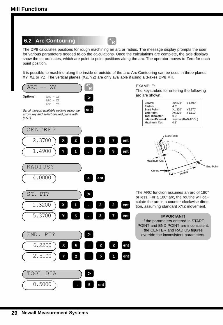
The DP8 calculates positions for rough machining an arc or radius. The message display prompts the userfor various parameters needed to do the calculations. Once the calculations are complete, the axis displaysshow the co-ordinates, which are point-to-point positions along the arc. The operator moves to Zero for eachpoint position.
It is possible to machine along the inside or outside of the arc. Arc Contouring can be used in three planes:XY, XZ or YZ. The vertical planes (XZ, YZ) are only available if using a 3-axes DP8 Mill.
The ARC function assumes an arc of 180°or less. For a 180o arc, the routine will cal-culate the arc in a counter-clockwise direc-tion, assuming standard XYZ movement.
2.3700
CENTRE?
2 ent
4.0000
RADIUS?
4 ent
Options: ARC - XYARC - XZARC - YZ
>
entScroll through available options using thearrow key and select desired plane with[ENT].
1.4900
X
Y
. 3 7
1 ent. 4 9
1.3200
ST. PT?
1 ent
5.3700
X
Y
. 3 2
5 ent. 3 7
6.2200
END. PT?
6 ent
2.5100
X
Y
. 2 2
2 ent. 5 1
>
>
Centre: X2.370” Y1.490”Radius: 4.0”Start Point: X1.320” Y5.370”End Point X6.220” Y2.510”Tool Diameter: 0.5”Internal/External: Internal (RAD-TOOL)Maximum Cut: 0.1”
RadiusCentre
Maximum Cut
Start Point
End Point
IMPORTANT!If the parameters entered in START
POINT and END POINT are inconsistent,the CENTER and RADIUS figures
override the inconsistent parameters.
0.5000
TOOL DIA
5 ent
>
.
6.2 Arc Contouring
R
Mill Functions
Newall Measurement Systems 30
MIL
LF
UN
CT
ION
S
RAD - TO O L
Options: RAD - TOOLRAD + TOOL
>
ent
0.1000
MAX CUT?
-1.3904
PT 1
-5.1098
X
Y
-5.9950
PT 65
-2.4504
X
Y
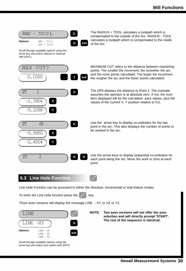
The RADIUS + TOOL calculates a toolpath which is compensated to the outside of the Arc. RADIUS - TOOLcalculates a toolpath which is compensated to the insideof the Arc.
Scroll through available options using thearrow key and select internal or externalwith (ENT).
1 ent.
PT 2
MAXIMUM CUT refers to the distance between machiningpoints. The smaller the increment, the smoother the arcand the more points calculated. The larger the increment,the rougher the arc and the fewer points calculated.
The DP8 displays the distance to Point 1. The exampleassumes the operator is at absolute zero. If not, the num-bers displayed will be the calculated axes values, plus thevalues of the current X, Y position relative to 0,0.
Use the arrow key to display co-ordinates for the lastpoint in the arc. This also displays the number of points tobe worked in the arc.
Use the arrow keys to display sequential co-ordinates foreach point along the arc. Move the work to Zero at eachpoint.
Line Hole Function can be accessed in either the Absolute, Incremental or Sub-Datum modes.
To enter the Line Hole function press the key.
Three axes versions will display the message LINE - XY, or XZ or YZ.
NOTE: Two axes versions will not offer the axes selection and will directly prompt 'START'. The rest of the sequence is identical.
LINE -XY
LINE
Options: LINE - XYLINE - XYLINE - YZ
>
ent
Scroll through available options using thearrow key and select your option with (ENT).
6.3 Line Hole Function
>
>
<
><
Mill Functions
Newall Measurement Systems31
X
Y
0
0
Length
30.0
Angle 45o
Start Point (10,10)
10.000
START
0 ent
30.000
LENGTH >
4
NO. HOLES
4 ent
>
45.000
ANGLE?
5 ent
>
-10.000
HOLE 1 >
-10.000
4
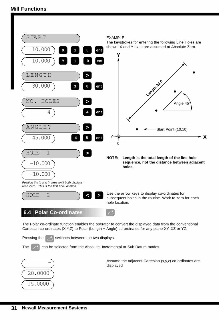
Position the X and Y axes until both displaysread Zero. This is the first hole location
HOLE 2 < > Use the arrow keys to display co-ordinates for subsequent holes in the routine. Work to zero for eachhole location.
10.000
1
0 ent1
0 ent3
The Polar co-ordinate function enables the operator to convert the displayed data from the conventionalCartesian co-ordinates (X,Y,Z) to Polar (Length + Angle) co-ordinates for any plane XY, XZ or YZ.
Pressing the switches between the two displays.
The can be selected from the Absolute, Incremental or Sub Datum modes.
-
20.0000
15.0000
Assume the adjacent Cartesian (x,y,z) co-ordinates aredisplayed
6.4 Polar Co-ordinates
EXAMPLE: The keystrokes for entering the following Line Holes areshown. X and Y axes are assumed at Absolute Zero.
NOTE: Length is the total length of the line hole sequence, not the distance between adjacent holes.
X
Y
Mill Functions
Newall Measurement Systems 32
POLAR- XY
P 22.360
A
-15.000
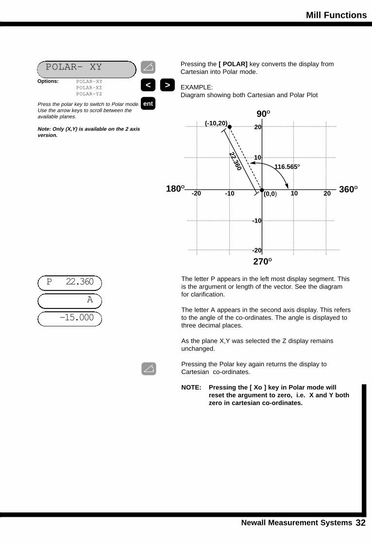
Pressing the [ POLAR] key converts the display fromCartesian into Polar mode.
EXAMPLE:Diagram showing both Cartesian and Polar Plot
Press the polar key to switch to Polar mode.Use the arrow keys to scroll between theavailable planes.
Note: Only (X,Y) is available on the 2 axisversion.
< >
ent
The letter P appears in the left most display segment. Thisis the argument or length of the vector. See the diagramfor clarification.
The letter A appears in the second axis display. This refersto the angle of the co-ordinates. The angle is displayed tothree decimal places.
As the plane X,Y was selected the Z display remainsunchanged.
Pressing the Polar key again returns the display toCartesian co-ordinates.
NOTE: Pressing the [ Xo ] key in Polar mode will reset the argument to zero, i.e. X and Y bothzero in cartesian co-ordinates.
Options: POLAR-XYPOLAR-XZPOLAR-YZ
(0,0)-10-20 2010
10
20
-10
-20
90O
180O
270O
360O
22.360
(-10,20)
116.565O
Lathe Functions
Newall Measurement Systems33
LA
TH
E F
UN
CT
ION
S
ABS
7.0 LATHE FUNCTIONS
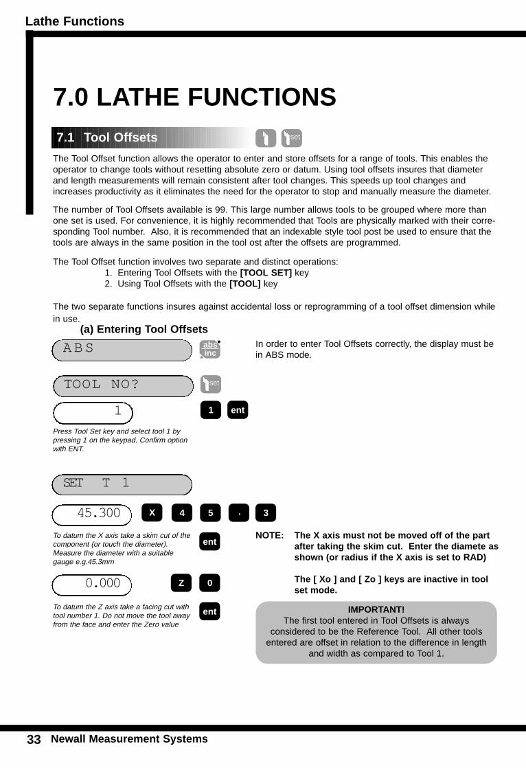
The Tool Offset function allows the operator to enter and store offsets for a range of tools. This enables theoperator to change tools without resetting absolute zero or datum. Using tool offsets insures that diameterand length measurements will remain consistent after tool changes. This speeds up tool changes andincreases productivity as it eliminates the need for the operator to stop and manually measure the diameter.
The number of Tool Offsets available is 99. This large number allows tools to be grouped where more thanone set is used. For convenience, it is highly recommended that Tools are physically marked with their corre-sponding Tool number. Also, it is recommended that an indexable style tool post be used to ensure that thetools are always in the same position in the tool ost after the offsets are programmed.
The Tool Offset function involves two separate and distinct operations:1. Entering Tool Offsets with the [TOOL SET] key2. Using Tool Offsets with the [TOOL] key
The two separate functions insures against accidental loss or reprogramming of a tool offset dimension whilein use.
(a) Entering Tool Offsetsabsinc
1
TOOL NO?
ent
45.300
ent
set
1
SET T 1
NOTE: The X axis must not be moved off of the part after taking the skim cut. Enter the diamete asshown (or radius if the X axis is set to RAD)
The [ Xo ] and [ Zo ] keys are inactive in tool set mode.
. 354
0.000 Z 0
ent
In order to enter Tool Offsets correctly, the display must bein ABS mode.
Press Tool Set key and select tool 1 bypressing 1 on the keypad. Confirm optionwith ENT.
To datum the Z axis take a facing cut withtool number 1. Do not move the tool awayfrom the face and enter the Zero value
To datum the X axis take a skim cut of thecomponent (or touch the diameter).Measure the diameter with a suitablegauge e.g.45.3mm
7.1 Tool Offsets set
X
IMPORTANT!The first tool entered in Tool Offsets is always
considered to be the Reference Tool. All other toolsentered are offset in relation to the difference in length
and width as compared to Tool 1.
Lathe Functions
Newall Measurement Systems 34
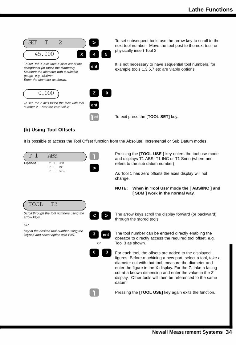
45.000
SET T 2
X
ent
0.000
To set subsequent tools use the arrow key to scroll to thenext tool number. Move the tool post to the next tool, orphysically insert Tool 2
Z
ent
To set the X axis take a skim cut of thecomponent (or touch the diameter).Measure the diameter with a suitablegauge e.g. 45.0mm Enter the diameter as shown.
To set the Z axis touch the face with toolnumber 2. Enter the zero value.
set
It is not necessary to have sequential tool numbers, forexample tools 1,3,5,7 etc are viable options.
(b) Using Tool Offsets
It is possible to access the Tool Offset function from the Absolute, Incremental or Sub Datum modes.
T 1 ABS Pressing the [TOOL USE ] key enters the tool use modeand displays T1 ABS, T1 INC or T1 Snnn (where nnnrefers to the sub datum number)
As Tool 1 has zero offsets the axes display will notchange.
NOTE: When in 'Tool Use' mode the [ ABS/INC ] and [ SDM ] work in the normal way.
>
TOOL T3
Options: T 1 ABST 1 INCT 1 Snnn
<
ent3
Scroll through the tool numbers using thearrow keys.
OR
Key in the desired tool number using thekeypad and select option with ENT.
The arrow keys scroll the display forward (or backward)through the stored tools.
The tool number can be entered directly enabling the operator to directly access the required tool offset. e.g.Tool 3 as shown.
For each tool, the offsets are added to the displayed figures. Before machining a new part, select a tool, take a diameter cut with that tool, measure the diameter andenter the figure in the X display. For the Z, take a facingcut at a known dimension and enter the value in the Z display. Other tools will then be referenced to the samedatum.
Pressing the [TOOL USE] key again exits the function.
>
4 5
0
>
or
0 3
To exit press the [TOOL SET] key.
Lathe Functions
Newall Measurement Systems35
LA
TH
E F
UN
CT
ION
S
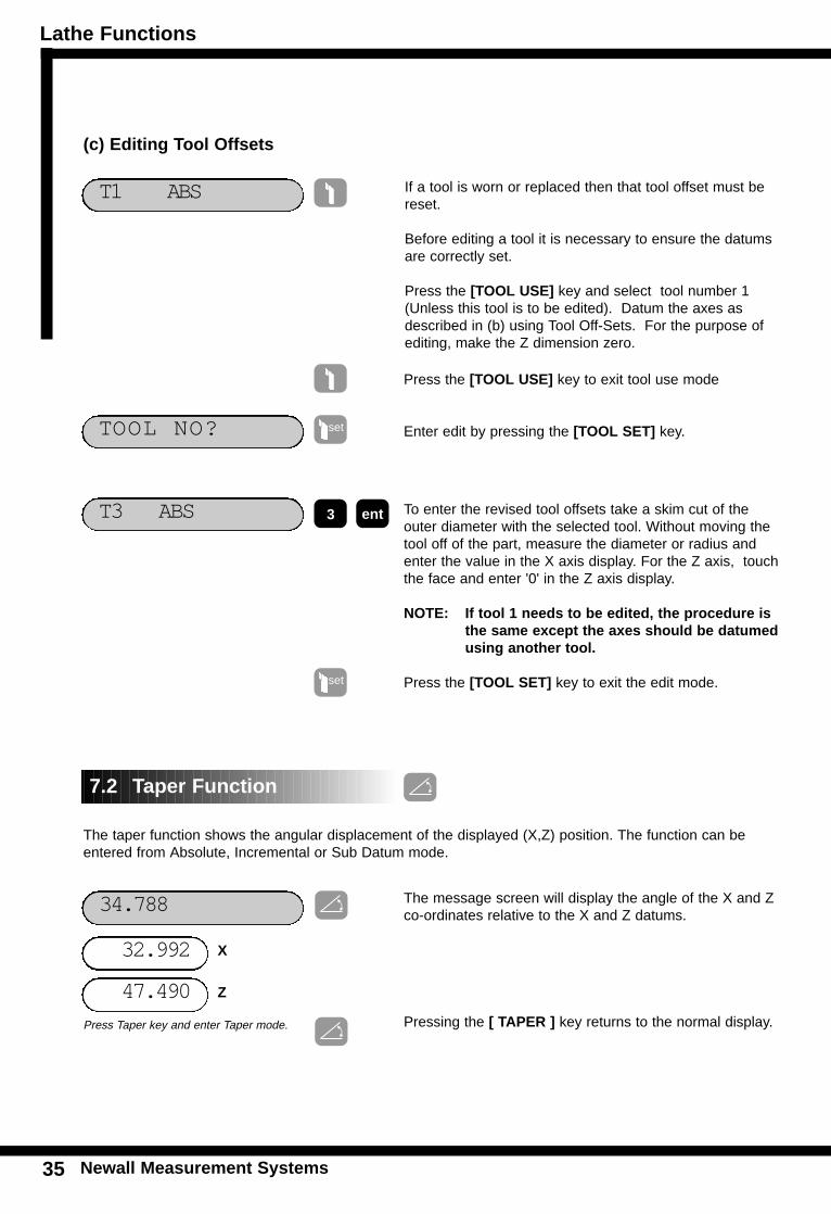
If a tool is worn or replaced then that tool offset must bereset.
Before editing a tool it is necessary to ensure the datumsare correctly set.
Press the [TOOL USE] key and select tool number 1(Unless this tool is to be edited). Datum the axes asdescribed in (b) using Tool Off-Sets. For the purpose ofediting, make the Z dimension zero.
T1 ABS
(c) Editing Tool Offsets
Press the [TOOL USE] key to exit tool use mode
Enter edit by pressing the [TOOL SET] key.
T3 ABS ent3
set
set
34.788
47.490
The message screen will display the angle of the X and Zco-ordinates relative to the X and Z datums.
Pressing the [ TAPER ] key returns to the normal display.Press Taper key and enter Taper mode.
32.992
7.2 Taper Function
The taper function shows the angular displacement of the displayed (X,Z) position. The function can beentered from Absolute, Incremental or Sub Datum mode.
TOOL NO?
To enter the revised tool offsets take a skim cut of theouter diameter with the selected tool. Without moving thetool off of the part, measure the diameter or radius andenter the value in the X axis display. For the Z axis, touchthe face and enter '0' in the Z axis display.
NOTE: If tool 1 needs to be edited, the procedure is the same except the axes should be datumed using another tool.
Press the [TOOL SET] key to exit the edit mode.
X
Z
Lathe Functions
Newall Measurement Systems 36
LA
TH
EF
UN
CT
ION
S
Z + Z > Z
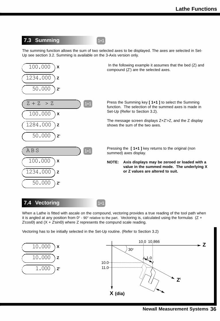
The summing function allows the sum of two selected axes to be displayed. The axes are selected in Set-Up see section 3.2. Summing is available on the 3-Axis version only.
50.000
In the following example it assumes that the bed (Z) andcompound (Z') are the selected axes.
1234.000
7.3 Summing 1+1
100.000
1+1
X
Z
Z’
50.000
1284.000
100.000 X
Z
Z’
Press the Summing key [ 1+1 ] to select the Summingfunction. The selection of the summed axes is made in Set-Up (Refer to Section 3.2).
The message screen displays Z+Z'>Z, and the Z displayshows the sum of the two axes.
ABS 1+1
50.000
1234.000
100.000 X
Z
Z’
Pressing the [ 1+1 ] key returns to the original (nonsummed) axes display.
NOTE: Axis displays may be zeroed or loaded with a value in the summed mode. The underlying Xor Z values are altered to suit.
When a Lathe is fitted with ascale on the compound, vectoring provides a true reading of the tool path whenit is angled at any position from 0° - 90° relative to the part. Vectoring is, calculated using the formulas (Z +ZlcosΘ) and (X + ZlsinΘ) where Z represents the compund scale reading.
Vectoring has to be initially selected in the Set-Up routine. (Refer to Section 3.2)
1.000
10.000
7.4 Vectoring 1+1
10.000 X
Z
Z’
Z
X (dia)
1.0
30o
10.011.0
10.0 10.866
Zl
Lathe Functions
Newall Measurement Systems37
LA
TH
E F
UN
CT
ION
S
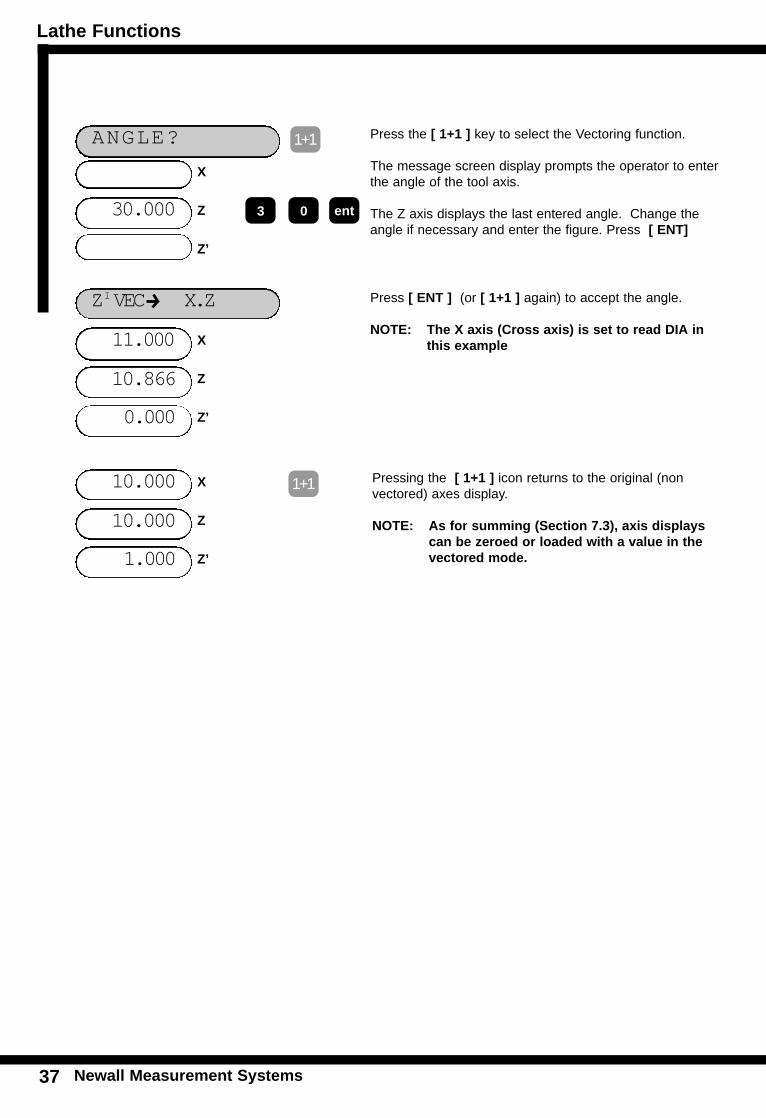
ANGLE? 1+1
30.000
X
Z
Z’
Press the [ 1+1 ] key to select the Vectoring function.
The message screen display prompts the operator to enterthe angle of the tool axis.
The Z axis displays the last entered angle. Change theangle if necessary and enter the figure. Press [ ENT]
ZIVEC X.Z
1+1
0.000
10.866
11.000 X
Z
Z’
Pressing the [ 1+1 ] icon returns to the original (non vectored) axes display.
NOTE: As for summing (Section 7.3), axis displays can be zeroed or loaded with a value in the vectored mode.
ent
1.000
10.000
10.000 X
Z
Z’
3 0
Press [ ENT ] (or [ 1+1 ] again) to accept the angle.
NOTE: The X axis (Cross axis) is set to read DIA in this example
Auxiliary Output Option
Newall Measurement Systems 38
AU
XIL
IAR
YO
UT
PU
TO
PT
ION
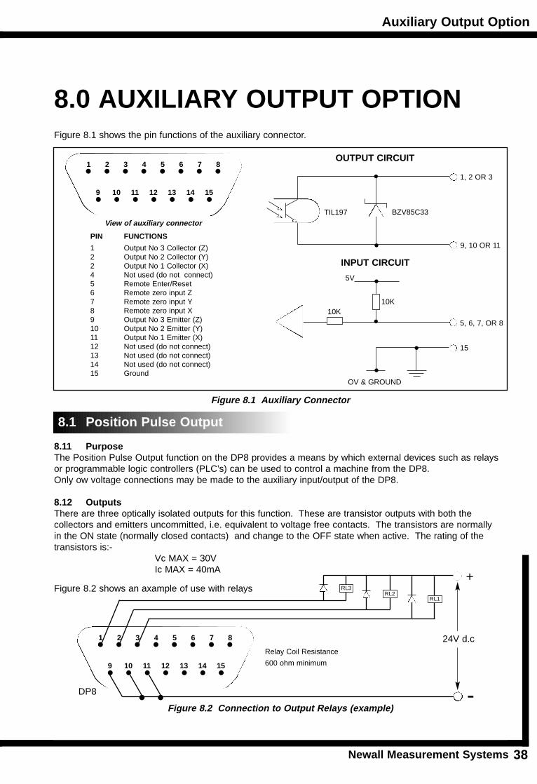
8.0 AUXILIARY OUTPUT OPTIONFigure 8.1 shows the pin functions of the auxiliary connector.
8.1 Position Pulse Output
8.11 PurposeThe Position Pulse Output function on the DP8 provides a means by which external devices such as relaysor programmable logic controllers (PLC’s) can be used to control a machine from the DP8.Only ow voltage connections may be made to the auxiliary input/output of the DP8.
8.12 OutputsThere are three optically isolated outputs for this function. These are transistor outputs with both the collectors and emitters uncommitted, i.e. equivalent to voltage free contacts. The transistors are normally in the ON state (normally closed contacts) and change to the OFF state when active. The rating of thetransistors is:-
Vc MAX = 30VIc MAX = 40mA
Figure 8.2 shows an axample of use with relays
PIN FUNCTIONS
1 Output No 3 Collector (Z)2 Output No 2 Collector (Y)2 Output No 1 Collector (X)4 Not used (do not connect)5 Remote Enter/Reset6 Remote zero input Z7 Remote zero input Y8 Remote zero input X9 Output No 3 Emitter (Z)10 Output No 2 Emitter (Y)11 Output No 1 Emitter (X)12 Not used (do not connect)13 Not used (do not connect)14 Not used (do not connect)15 Ground
1 2 3 4 5 6 7 8
9 10 11 12 13 14 15
OUTPUT CIRCUIT
INPUT CIRCUIT
TIL197 BZV85C33
1, 2 OR 3
9, 10 OR 11
5, 6, 7, OR 8
5V
10K
OV & GROUND
15
10K
Figure 8.1 Auxiliary Connector
View of auxiliary connector
1 2 3 4 5 6 7 8
9 10 11 12 13 14 15
RL3RL2
RL1
24V d.cRelay Coil Resistance
600 ohm minimum
-
+
DP8
Figure 8.2 Connection to Output Relays (example)
Auxiliary Output Option
Newall Measurement Systems
8.13 InputsThere is one input which may be used to reset the position pulse output function. This input is grounded tocause a reset. e.g. a switch or relay contact may be used.
8.14 OperationThere are two modes of operation; single axis or all axis.
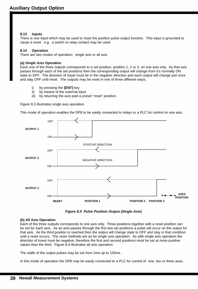
(a) Single Axis OperationEach one of the three outputs corresponds to a set position, position 1, 2 or 3, on one axis only. As that axispasses through each of the set positions then the corresponding output will change from it’s normally ONstate to OFF. The direction of travel must be in the negative direction and each output will change just onceand stay OFF until reset. The outputs may be reset in one of three different ways;
i) by pressing the [ENT] keyii) by means of the external input iii) by returning the axis past a preset “reset” position.
Figure 8.3 illustrates single axis operation.
This mode of operation enables the DP8 to be easily connected to relays or a PLC for control on one axis.
39
AU
XIL
IAR
Y O
UT
PU
T O
PT
ION
OUTPUT 1
OUTPUT 2
OUTPUT 3
RESET POSITION 1 POSITION 2 POSITION 3
OFF
ON
OFF
ON
OFF
ON
Figure 8.3 Pulse Position Output (Single Axis)
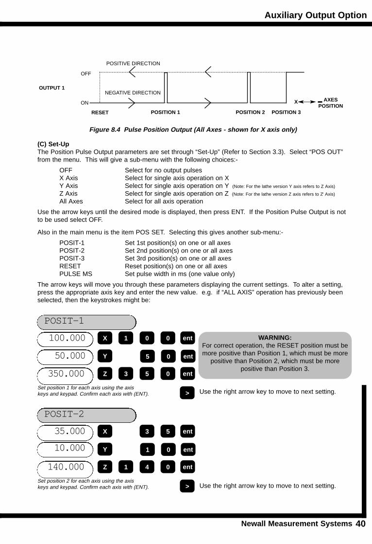
(b) All Axis OperationEach of the three outputs corresponds to one axis only. Three positions together with a reset position canbe set for each axis. As an axis passes through the first two set positions a pulse will occur on the output forthat axis. As the third position is reached then the output will change state to OFF and stay in that conditionuntil a reset occurs. The reset methods are as for single axis operation. As with single axis operation thedirection of travel must be negative, therefore the first and second positions must be set at more positive values than the third. Figure 8.4 illustrates all axis operation.
The width of the output pulses may be set from 2ms up to 120ms.
In this mode of operation the DP8 may be easily connected to a PLC for control of one, two or three axes.
AXESPOSITION
X
POSITIVE DIRECTION
NEGATIVE DIRECTION
Auxiliary Output Option
Newall Measurement Systems 40
AU
XIL
IAR
YO
UT
PU
TO
PT
ION
(C) Set-UpThe Position Pulse Output parameters are set through “Set-Up” (Refer to Section 3.3). Select “POS OUT”from the menu. This will give a sub-menu with the following choices:-
OFF Select for no output pulsesX Axis Select for single axis operation on XY Axis Select for single axis operation on Y (Note: For the lathe version Y axis refers to Z Axis)
Z Axis Select for single axis operation on Z (Note: For the lathe version Z axis refers to Zl Axis)
All Axes Select for all axis operation
Use the arrow keys until the desired mode is displayed, then press ENT. If the Position Pulse Output is notto be used select OFF.
Also in the main menu is the item POS SET. Selecting this gives another sub-menu:-
POSIT-1 Set 1st position(s) on one or all axesPOSIT-2 Set 2nd position(s) on one or all axesPOSIT-3 Set 3rd position(s) on one or all axesRESET Reset position(s) on one or all axesPULSE MS Set pulse width in ms (one value only)
The arrow keys will move you through these parameters displaying the current settings. To alter a setting,press the appropriate axis key and enter the new value. e.g. if “ALL AXIS” operation has previously beenselected, then the keystrokes might be:
OUTPUT 1
RESET POSITION 1 POSITION 2 POSITION 3
OFF
ON
Figure 8.4 Pulse Position Output (All Axes - shown for X axis only)
AXESPOSITION
X
POSIT-1
350.000
50.000
100.000
ent5 0
ent0 0
ent5 0
X 1
Y
Z 3
>Set position 1 for each axis using the axis keys and keypad. Confirm each axis with (ENT). Use the right arrow key to move to next setting.
POSIT-2
140.000
10.000
35.000
ent1 0
ent3 5
ent4 0
X
Y
Z 1
>Set position 2 for each axis using the axis keys and keypad. Confirm each axis with (ENT). Use the right arrow key to move to next setting.
POSITIVE DIRECTION
NEGATIVE DIRECTION
WARNING: For correct operation, the RESET position must bemore positive than Position 1, which must be more
positive than Position 2, which must be more positive than Position 3.
Auxiliary Output Option
Newall Measurement Systems41
AU
XIL
IAR
Y O
UT
PU
T O
PT
ION
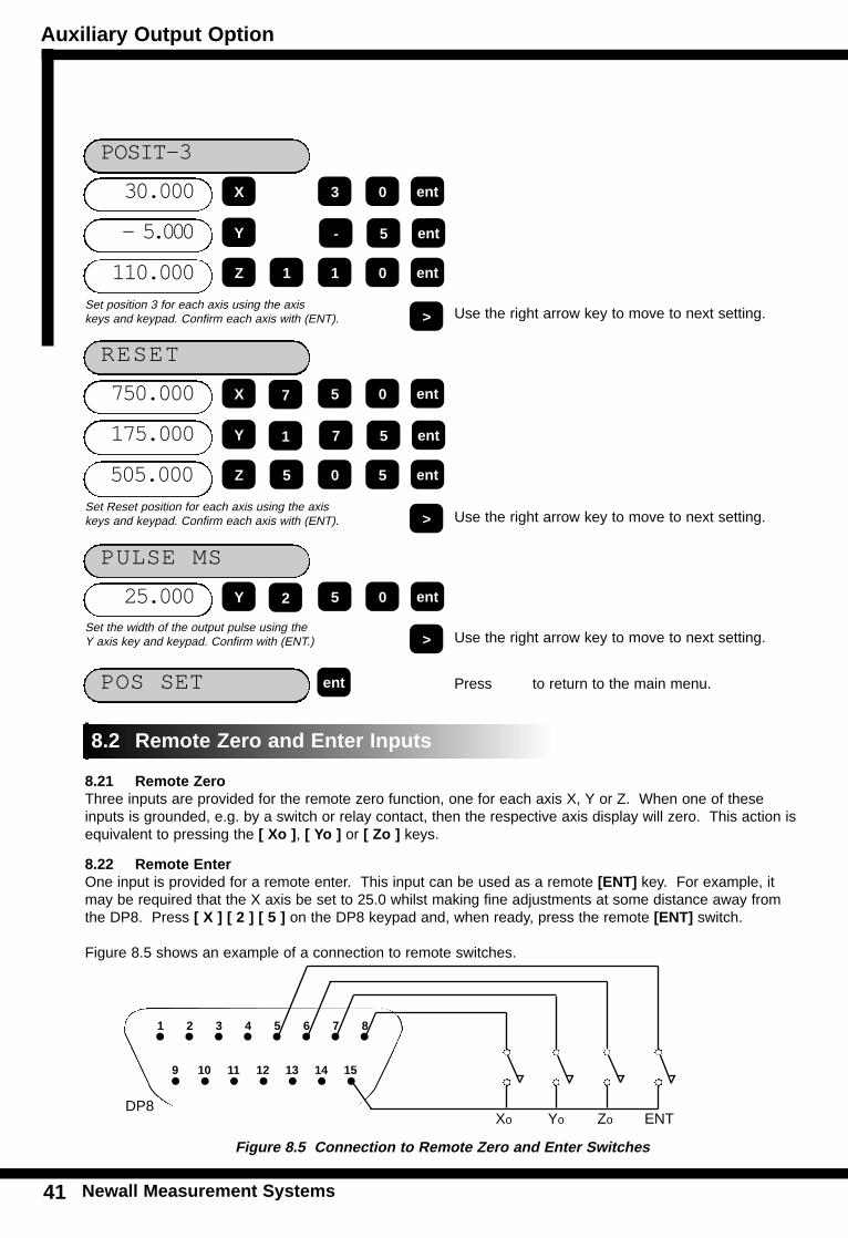
RESET
505.000
175.000
750.000
ent7 5
ent5 0
ent0 5
X
Y
Z 5
>Set Reset position for each axis using the axis keys and keypad. Confirm each axis with (ENT).
7
1
PULSE MS
25.000 ent5 0Y
>Set the width of the output pulse using the Y axis key and keypad. Confirm with (ENT.)
2
POS SET ent
Use the right arrow key to move to next setting.
Use the right arrow key to move to next setting.
Press to return to the main menu.
8.21 Remote ZeroThree inputs are provided for the remote zero function, one for each axis X, Y or Z. When one of theseinputs is grounded, e.g. by a switch or relay contact, then the respective axis display will zero. This action isequivalent to pressing the [ Xo ], [ Yo ] or [ Zo ] keys.
8.22 Remote EnterOne input is provided for a remote enter. This input can be used as a remote [ENT] key. For example, itmay be required that the X axis be set to 25.0 whilst making fine adjustments at some distance away fromthe DP8. Press [ X ] [ 2 ] [ 5 ] on the DP8 keypad and, when ready, press the remote [ENT] switch.
Figure 8.5 shows an example of a connection to remote switches.
8.2 Remote Zero and Enter Inputs
1 2 3 4 5 6 7 8
9 10 11 12 13 14 15
Xo Yo Zo ENTDP8
Figure 8.5 Connection to Remote Zero and Enter Switches
POSIT-3
110.000
- 5.000
30.000
ent- 5
ent3 0
ent1 0
X
Y
Z 1
>Set position 3 for each axis using the axis keys and keypad. Confirm each axis with (ENT). Use the right arrow key to move to next setting.
Troubleshooting / Cleaning
Newall Measurement Systems 42
TR
OU
BL
ES
HO
OT
ING
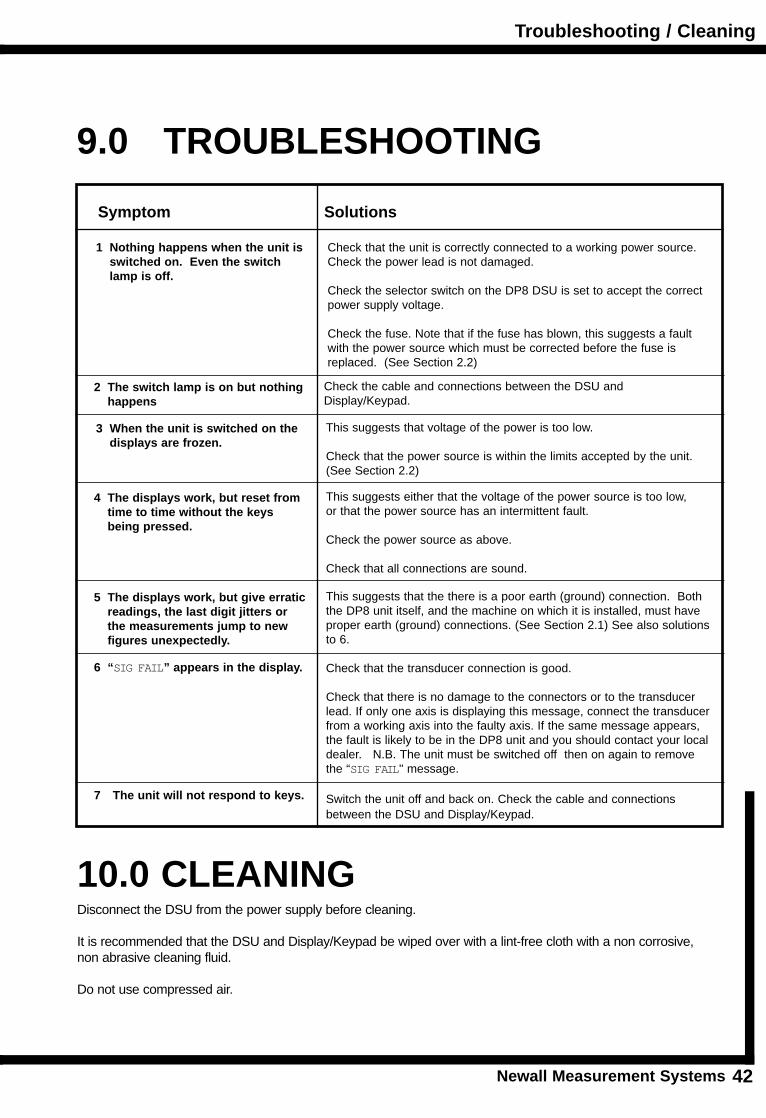
9.0 TROUBLESHOOTING
Symptom Solutions
10.0 CLEANINGDisconnect the DSU from the power supply before cleaning.
It is recommended that the DSU and Display/Keypad be wiped over with a lint-free cloth with a non corrosive, non abrasive cleaning fluid.
Do not use compressed air.
1 Nothing happens when the unit is switched on. Even the switch lamp is off.
Check that the unit is correctly connected to a working power source.Check the power lead is not damaged.
Check the selector switch on the DP8 DSU is set to accept the correct power supply voltage.
Check the fuse. Note that if the fuse has blown, this suggests a fault with the power source which must be corrected before the fuse is replaced. (See Section 2.2)
3 When the unit is switched on the displays are frozen.
4 The displays work, but reset from time to time without the keys being pressed.
5 The displays work, but give erraticreadings, the last digit jitters or the measurements jump to new figures unexpectedly.
6 “SIG FAIL” appears in the display.
7 The unit will not respond to keys.
This suggests that voltage of the power is too low.
Check that the power source is within the limits accepted by the unit.(See Section 2.2)
This suggests either that the voltage of the power source is too low,or that the power source has an intermittent fault.
Check the power source as above.
Check that all connections are sound.
This suggests that the there is a poor earth (ground) connection. Boththe DP8 unit itself, and the machine on which it is installed, must haveproper earth (ground) connections. (See Section 2.1) See also solutionsto 6.
Check that the transducer connection is good.
Check that there is no damage to the connectors or to the transducer lead. If only one axis is displaying this message, connect the transducerfrom a working axis into the faulty axis. If the same message appears,the fault is likely to be in the DP8 unit and you should contact your localdealer. N.B. The unit must be switched off then on again to removethe “SIG FAIL" message.
Switch the unit off and back on. Check the cable and connectionsbetween the DSU and Display/Keypad.
2 The switch lamp is on but nothinghappens
Check the cable and connections between the DSU andDisplay/Keypad.

NEWALL MEASUREMENT SYSTEMS LTD64 Percy Road . Leicester . LE2 8FN . England
Tel: (44) 0116 283 3899 . Fax: (44) 0116 283 5530E-mail: [email protected]
NEWALL FRANCE SARL63 Rue Victor Hugo . F-59200 . Tourcoing . France
Tél. 03 20 01 03 13 . Fax 03 20 26 13 41
NEWALL ELECTRONICS INC1778 Dividend Drive . Columbus . Ohio . 43228 . USA
Tel: (1) 614 - 771 0213 . Fax: (1) 614 - 771 0219E-mail: [email protected]
Website:www.newall.co.uk
Code: 023-12560 UK Issue Date: November 1998