Embed Size (px)
Citation preview

Disclosure to Promote the Right To Information
Whereas the Parliament of India has set out to provide a practical regime of right to information for citizens to secure access to information under the control of public authorities, in order to promote transparency and accountability in the working of every public authority, and whereas the attached publication of the Bureau of Indian Standards is of particular interest to the public, particularly disadvantaged communities and those engaged in the pursuit of education and knowledge, the attached public safety standard is made available to promote the timely dissemination of this information in an accurate manner to the public.
इंटरनेट मानक
“!ान $ एक न' भारत का +नम-ण”Satyanarayan Gangaram Pitroda
“Invent a New India Using Knowledge”
“प0रा1 को छोड न' 5 तरफ”Jawaharlal Nehru
“Step Out From the Old to the New”
“जान1 का अ+धकार, जी1 का अ+धकार”Mazdoor Kisan Shakti Sangathan
“The Right to Information, The Right to Live”
“!ान एक ऐसा खजाना > जो कभी च0राया नहB जा सकता है”Bhartṛhari—Nītiśatakam
“Knowledge is such a treasure which cannot be stolen”
“Invent a New India Using Knowledge”
है”ह”ह
IS 12560 (1988): Code of practice for cathodic protectionof heat exchangers and condensers [MTD 7: Light Metals andtheir Alloys]

IS 12560 : 1988
Indian Standard
CODEOFPRACTICEFOR CATHODICPROTECTIONOFHEAT EXCHANGERSANDCONDENSERS
(First Reprint NOVEMBER 1990)
UDC 621’175 : 620’197’5
BUREAU OF INDIAN STANDARDS MANAK BIiAVAN, 9 BAHADUR SHAH ZAFAK MARG
NEW DELHI 110002
October 1989 Price Group 3
Corrosion Protection Sectional Committee, SMDC 29
FOREWORD
This Indian Standard was adopted by the Bureau of Indian Standards on 6 October 1988, after the draft finalized by the Corrosion Protection Sectional Committee had been approved by the Structural and Metals Division Council.
Metallic surfaces of water boxes, tube plates and tubes of heat exchangers and condensers using corrosive cooling water are subject to general corrosion and pitting. corrosion depends on the corrosion resistance of metals,
The nature and intensity of design and fabrication process of the
components, characteristics of cooling water velocity of cooling water and performances of coating, if applied to bare parts of the metal.
Commonly used materials of construction for water boxes, tube plates and tubes of heat exchangers/condensers vary from design to design, Conditions. of severe corrosion leading to perforations and thinning arise, if materials possess susceptibility to corrosion-erosion attack and if they arc galvanically dissimilar in corrosive cooling water environment. Cathodic protection in conjunction with anti-corrosive paints in water boxes can provide satisfactory corrosion protection to corrodjng components and ensures longer life of the heat exchangers/condensers. Establishing the standard requirements for optimum corrosion control using cathodic protection is, therefore, a pre-requisite to maintain a factor of higher reliability in the maintenance of heat exchangers/condensers except these where titanium is used as a construction material. This standard can also be used as a guideline for the use of cathodic protection systems as well as the selection of materials for cooling water systems of heat exchangers/condensers.
IS 12560 : 1988
Indian Standard
CODE OFPRACTICEFOR CATHODICPROTECTIONOFHEAT EXCHANGERSANDCQNDENSERS
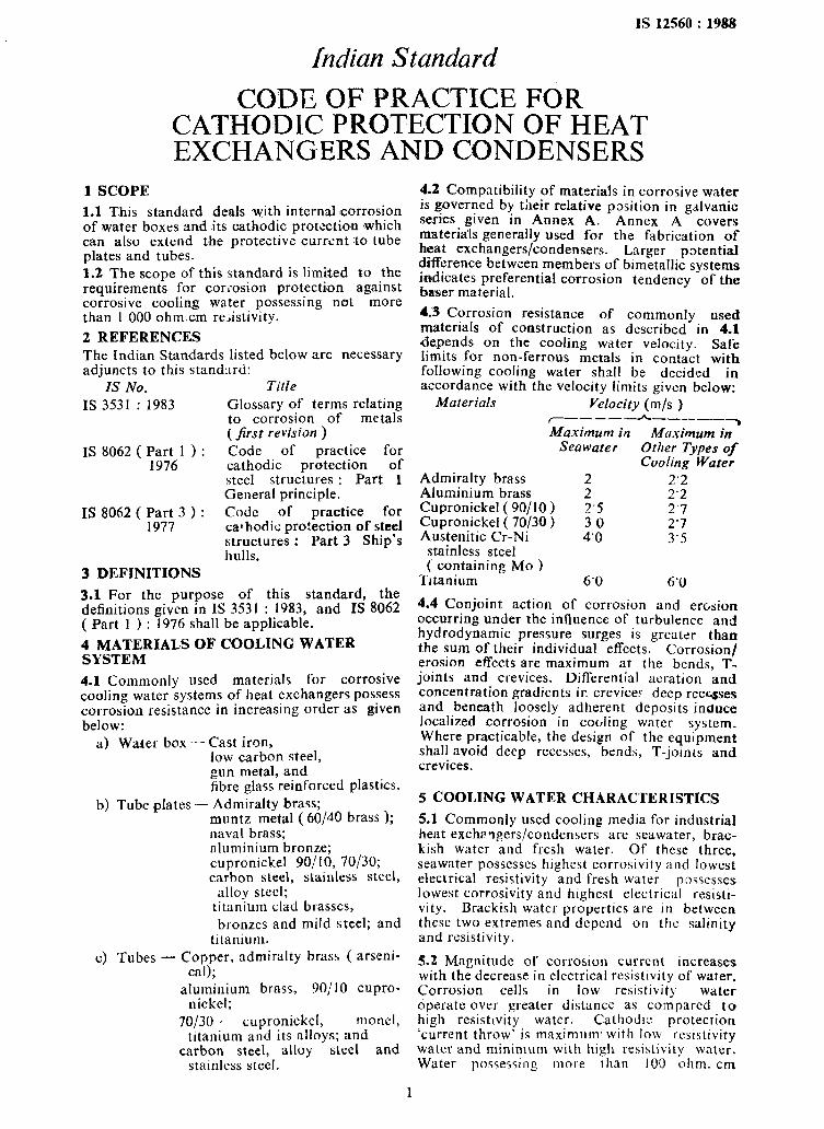
1 SCOPE
1.1 This standard deals ,with internal corrosion of water boxes and its cathodic protection ,which can also extend the protective currtint to tube plates and tubes.
1.2 The scope of this standard is limited to the requirements for COriosion protection against corrosive cooling water possessing not more than 1 000 ohmcm resistivity.
2 REFERENCES
The Indian Standards listed below are necessary adjuncts to this stand:lrd:
IS No. Title
IS 3531 : 1983 Glossary of terms relating to corrosion of metals ( first revision )
IS 8062 ( I”;kl > : Code of practice for cathodic protection of steel structures : Part 1 General principle.
IS 8062 (Part 3): Code of practice for 1977 cathodic protection of steel
structures : Part 3 Ship’s hulls.
3 DEFINITIONS
3.1 For the purpose of this standard, the definitions given in IS 3531 : 1983, and IS 8062 ( Part 1 ) : 1976 shall be applicable.
4 MATERIALS OF COOLING WATER SYSTEM
4.1 Commonly used materials for corrosive cooling water systems of heat exchangers possess corrosion resistance in increasing order as given below:
a) Water box - Cast iron, low carbon steel, gun metal, and fibre glass reinforced plastics.
b) Tube plates - Admiralty brass; muntz metal ( 60/4O brass );
c) Tubes
naval brass; aluminium bronze; cupronickel 90110, 70130; carbon steel, stainless steel,
alloy steel; titanium clad brasses, bronzes and mild steel; and
titanium. Cc;y)per, admiralty brass ( arscni-
; aluminium brass, 90/10 cupro-
nickel; 70130 ’ cupronickcl, monel,
titanium and its alloys; and carbon steel, alloy steel and
stainless steel,
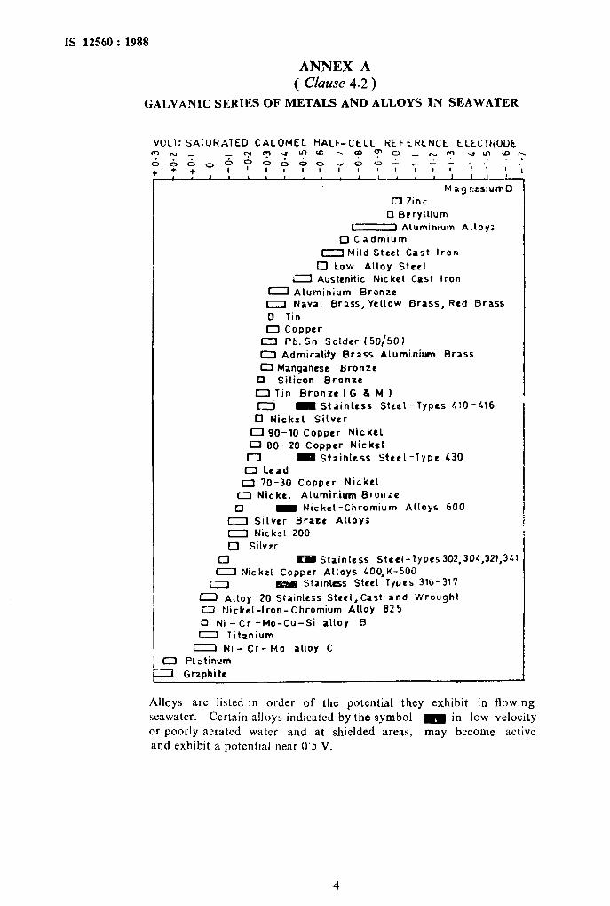
4.2 Compatibility of materials in corrosive water is governed by their relative position in galvanic series given in Annex A. Annex A covers materials generally used for the fabrication of heat exchangers/condensers. Larger potential difference between members of bimetallic systems indicates preferential corrosion tendency of the baser material.
4.3 Corrosion resistance of commonly used materials of construction as described in 4.1 <depends on the cooling water velocity. Safe limits for non-ferrous metals in contact with following cooling water shall be decided in accordance with the velocity limits given below:
Materials Velocity (m/s ) ~_-___h_-_.__- Maximum in Muximum in7
Sea water Other Types of Cooling Water
Admiralty brass Aluminium brass Cupronickel ( 90/10 ) Cupronickel ( 70/30)
2.2 f 2’2
3”‘; 2’7 2’7
Austenitic Cr-Ni stainless steel
4’0 3’5
( containing MO ) Titanium 6’0 6’0
4.4 Conjoint action of corrosion and erosion occurring under the influence of turbulence and hydrodynamic pressure surges is greater than the sum of their individual effects. Corrosion/ erosion effects are maximum at the bends, T- joints and crevices. Differential aeration and concentration gradients ir crevice? deep recqses and beneath loosely adherent deposits induce localized corrosion in cooling water system. Where practicable, the design of the equipment shall avoid deep recesses, bends, T-joints and crevices.
5 COOLING WATER CHARACTERISTICS
5.1 Commonly used cooling media for industrial heat exchangers/condensers are seawater, brac- kish water and fresh water. Of these three, seawater possesses highest corrosivity and lowest electrical resistivity and fresh water poqcesses lowest corrosivity and highest electrical resisti- vity. Brackish water properties are in between these two extremes and depend on the salinity and resistivity.
5.2 Magnitude of corrosion current increases with the decrease in electrical resistivity of water. Corrosion cells in low resistivity water operate over greater distance as compared to high resistivity water. Cathodic protection ‘current throw’ is maximum. with low rcsistivity water and minimum with high resistivity water. Water possessing more than 100 ohm. cm
1
IS 12560:1988
resistivity is not adequate for satisfactory current throw.
5.3 Corrosivity of seawater is more aggressive with the addition of ppm level sulphide and ammonia content. Presence of sulphides and ammonia in fertilizer and chemical industry, etc, are likely to cause enhanced localized pitting, enhanced crevices corrosion and render copper base alloys susceptible to pitting as well as stress corrosion cracking. Maximum lolerable limits of these species in cooling seawater as given in Annex B shall be applicable to 9015, 9OjlO and 70130 cupronickel, aluminium brass, aluminium bronze admiralty bras, muntz metal and naval brass.
6 PROTECTIVE COATINGS
6.1 Application of anticorrosive coatings reduces the magnitude of corrosion current as well as reduces the requirement of cathodic protection current.
6.2 Painting of water boxes for corrosion resis- tance shall be carried out according to IS 8062 ( Part 3 ) : 1977 when fabricated out of ferrous materials.
7 CATHODIC PROTECTION
7.1 Cathodic protection for heat exchangers/ condensers is desirable, if the cumulative effect of the following factors leads to severe and unpredictable corrosion damage:
a>
b)
c)
Large potential difference between mate- rials of water boxes, tube plates and tubes,
Cooling water possessing low resistivity and high corrosivity; and
Difficulty of application and maintenance painting of water boxes.
7.2 Cathodic protection cannot prevent corro- sion of metallic surfaces beyond the reach of protective currents. In high resistivity cooling water, protective potential attenuation is achieved faster and, therefore, uniform potential spread is more difficult to achieve with one or two anodes.
7.3 Protective potential more negative than -0’7 Yscn may lead to hydriding of titanium surfaces leading to embrittlement and cracking of titanium material.
7.4 Cathodic protection is best achieved when applied to wster boxes. installation of anodes on tube plates is not desirable from design point of view. Such installation is likely to cause excessive turbulence leading to erosion.
7.6.1 Protective potential criterion for various materials is diffcrcnt in diffcrcnt corrosive media. The following values arc applicable in seawater medium. These V~IUCS may bc adopted fcr ch]cridc containing waters of lower
resistivity:
Plain carbon and low - 0’78 vscs alloy steels
Brasses and bronzes - 0’550 Vsce Cupronickels - 0’600 VSCE
7.4.2 In respect of sulphide contaminated water, protective potential shall be 100 mV more negatives from the values given in 7.4.1.
7.5 Both galvanic and impressed current methods of cathodic protection are applicable for installation of cathodic protection system. Choice between the two methods depends upon the economics, design factors, protective current demand and time gap between two successive inspection schedules.
8 GALVANIC ANODE SYSTEM
8.1 Galvanic cathodic protection is easier for installation and no maintenance is required. Potential monitoring is not essential and is left to the discretion of the user. Poten- tial monitoring shall be achieved by install- ing rugged silver/silver chloride electrode on the protected surface away from the anode location and taking out the cable lead through sealed perforation. Potential difference between the structure and reference silver/silver chloride electrode shall be measured using high impe- dance voltmeter.
8.2 Pure zinc possesses property of polarity re- versal at higher temperatures. Therefore, caution sh’buld be exercised in using zinc anodes where temperature is likely to increase beyond 40°C. It is desirable to indicate values of zinc anode potentials and anode current efficiencies at temperatures beyond 40°C. Magnesium based anodes possess high driving voltage and, therefore, are not desirable for heat exchanger service. Aluminium based composition of current etficiency better than 70 percent arc desirable for use as galvanic anodes.
8.3 Where water boxes are composed of cast copper based alloys, plain carbon unalloyed steel anodes may be used with advantage of forming corrosion resistant layer on tube interiors.
8.4 Purchaser of anodes shall stipulate the major requirements/characteristics of the anode material and anode design. For purpose of guidance, the characteristics of aluminium, zinc, magnesium and iron based commonly used cornposrtions are given in Annex C.
9 DESIGN AND INSTALLATION OF GALVANIC ANODES
9.1 Cathodic protection of heat exchangers/ condensers is desirable on water boxes. ‘I’ubc pl:ltcs and small lengths of the tubes may rcccivc protective current depending on the resistivity of the cooling water and contact resistance between water box and tube platc/tubcs. Design of the cathodic protection system shall be based on corrosion protection aspects of both the
2
IS 12560 : 1988
inlet as well as outlet water boxes. Cooling water temperature shall be taken into account.
9.2 Minimum turbulence shall be effected by installation of galvanic anodes on the interior of water box cover. The anodes shall have a cast-in insert designed in such a way that the anode may be screwed on the interior water box cover. Centrally located anode may give uniform spread of protective current.
10 IMPRESSED CURRENT CATHODTC PROTECTION ( JCCP ) SYSTEM AND ITS INSTALLATION
10.1 Impressed current cathodic protection system provides protective current from external dc source through anodes of inert nature to the corroding structure. The system shall be capable of monitoring/measuring the protective potential by means of reference electrode fitted on the protected structure.
10.1.1 Protective potential is closely maintained to a preset reference value ( desired protective potential value ) in ICCP control equipment. Electronic circuit and design of the control equipment shall be so constructed that dc output shall get automatically adjusted to a value required to maintain the desired protective potential. The tolerance limits for protcctivc potential shall be a matter decided by mutual agreement between the concerned parties.
10.2 The control equipment shall have rhe capacity for continuous operation throughout the operating period of the condenser/heat exchanger. A pure dc output is most desirable, however, if ac ripples exist in dc output, the peak-to-peak voltage of these ripples shall be within the protective potential limits. The nature, type and dimensions of the equipment shall be left to the disc!-ction of the user.
10.3 Anodes
ICCP anodes shall be composed of such mate- rials which do nol form anodic loose deposits. It is preferable to use platinum clad or platinized titanium or pure platinum wire or foil as I CCP anode material.
10.3.1 Anode construction shall incorporate properly insulated connecting leads and insulat- ing anode backing. The insulating material shall be water resistant and shall resist tempera- tures up to 50°C.
11 GUIDELINES FOR DESIGN OF CATHODIC PROTECTION SYSTEM
11.1 The guidelines before adopting the cathodic protection systems are given in 11.1.1 to 11.1.5.
11.1.1 Cooling water resistivity shall be estab- lished by using conductivity meter meant for electrolytic solutions.
11.1.2 Total current requirement for cathodic protection depends on corrosivity/resistivity of the cooling water and the protective coating applied on water boxes. Typical values of current requirements for ferrous metals are given in Annex D, for guidance.
11.1.3 Requirements for the insulating backing of the anodes shall be ascertained. Insulating backing is specifically rcquircd for impressed current anodes to achieve better current distri- bution.
11.1.4 Sclcctlon of suitable anode shall be done by mutual agreement between the concerned partIcs. Anode spacing shall IX decided taking into consideration the a\~dilable space and
current distribution.
11.1.5 Circuit resistances sllall 1)~ clctclmincd.
IS 12560 : 1988
ANNEX A ( Clause 4.2 )
GALVANIC SERIES OF METALS AND ALLOYS IN SEAWATER
0 Ni - Cr- MO alloy C
CZl Platinum
1 Graphite
P-1 ag nes:umO 0 Zinc
0 Brryllium
I Alumintum AlLoy: 0 C admlum
-Mild Steel Cast Iron 0 Low Alloy Steel
11 Austcnitic Nlc kel Cast Iron
0 Aluminium Bronze I Naval Brass, Yellow Brass, Red Brass
0 Tin
0 Copper 0 Pb. Sn Solder I50/50)
0 Adminlity Brass ALumi.niwn Brass
0 Manganese Bronze 0 Silicon Bronze
OTin BronteiG d, M 1 Cl _ Stainless Steel -Types LlO-116
0 Nickrl Silver
0 90-10 Copper Nickel
0 80-20 Copper Nickel
0 m Stainless Steel -Type L30
0 Lead
o 70-30 Copper Nickel
0 Nickel Aluminiurn Bronze
0 m Nickel -Chromium Alloys 600
0 Silver Braze Alloys
0 Nick21 200
r] Silvrr
0 B Stainless Steel-Types 302,301,321,3LJ
I Nickel Copper Alloys LOO,K-500
0 N Stainless Steel Types 316-317
0 Alloy 20 SPatniess Stcel,Cast and Wrought IX Nickel-Iron-Chromium Alloy 825
0 Ni -Cr -Mo-Cu-Si alloy B 0 Titanium
Alloys are listed in order of the potential they exhibit in flowing
seawater. Certain alloys indicated by the symbol 0 in low velocity
or poorly aerated water and at shielded areas, may become active and exhibit a potential near 0’5 V.
4
IS 12560 :1988
ANNEX B ( Chse5.3 )
TOLERANCE LIMITS OF HARMFUL SPECIES IN COOLING WATER
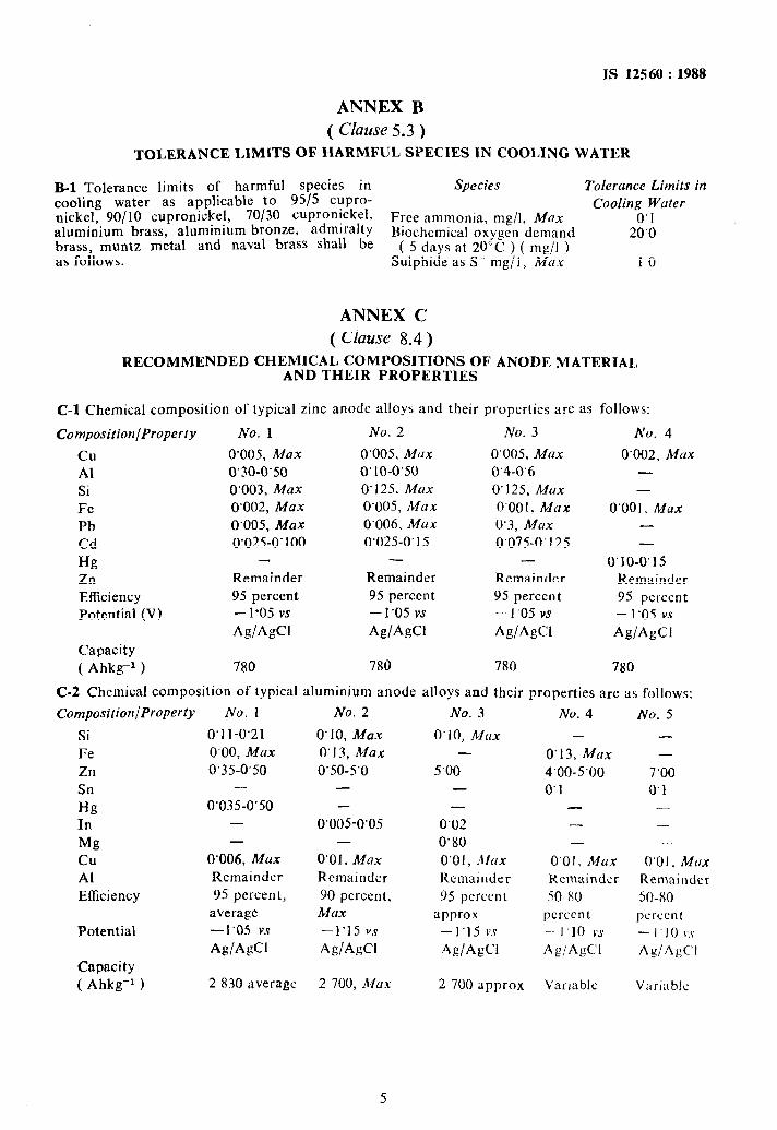
B-l Tolerance limits of harmful species in Species Tolerance Limits in cooling water as applicable to 9515 CuPro- nickel, 90110 cupronickel, 70/30 cupronickel,
Cooling Water
aluminium brass, aluminium bronze, admiralty Free ammonia, mg/l, Mnx 0’1
brass, muntz metal and naval brass shall be Biochemical oxygen demand 20‘0
( 5 days at 20°C ) ( mg/l ) as follows: Sulphide as S- mg/l, MUX 1’0
ANNEX C ( Clause 8.4)
RECOMMENDED CHEMICAL COMPOSITIONS OF ANODE MATERIAL AND THEIR PROPERTlES
C-I Chemical composition of typical zinc anode alloys and their properties are as follows:
Composition/Property No. 1 No. 2 No. 3 No. 4
cu O’OOS, Max 0’005, MUX 0’005, MUX 0’002, Mu Al 0’30-0’50 0’10-0’50 0’4-0’6 -
Si 0’003, Max 0’125. Max 0’125, MUX -
Fe 0'002, Max 0’005, Max 0’001, Max 0’001, Max Pb 0’005, Max 0’006, Max 0’3, Max -
Cd 0’025-0’100 0’025-0’15 0‘075-0’125 -
Hg - - 0’10-0’15
Zn Remainder Remainder Remainder Remainder
Efficiency 95 percent 95 percent 95 percent 95 percent Potential (V) - 1’05 vs -1’05 vs - 1’05 vs - 1’05 vs
AglAgCl AglAgCl AglAgCl AglAgCl Capacity ( Ahkg-’ ) 780 780 780 780
C-2 Chemical composition of typical aluminium anode alloys and their properties are as fol]ows:
Composition/Property No. 1
Si 0’1 l-O.21
Fe 0’00, Max Zn 0.35-0’50
Sn -
Hg 0’035-0’50 In -
Mg -
cu 0’006, Max Al Remainder
Efficiency 95 percent,
average
Potential -1’05 vs
Ag/AgCl
Capacity ( Ahkg-’ ) 2 830 ;IVerage
No. 2
0’10, MUX 0’13, Max 0’50-5’0
-
-
0’005-0’05 -
0’01, Max Remainder
90 percent, Max -1’15 vs
AgiAgCl
2 700, i2fux
No. 3
0‘10, MUX -
5’00 -
-
0’02
0’80
0’0 I ) Max Remainder
95 percent
approx -1’15 vs
As/A&l
2 700 approx
No. 4
-
0’13, Max
4’00-5.00 0’1
- - -
0'01, Max Kemainder
SO-80
pcrccn t
- I 10 vs Ag/AgCI
Variable
No. 5
- -
7’00 0’1
-
- -
0’01, MNX Remainder
50-80
percent
- I IO v.s Ag/AgC’I
V:irrilblc
IS 12560 : 1988
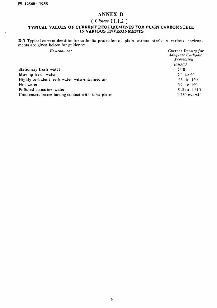
ANNEX D ( Clause 11.1.2 )
TYPICAL VALUES OF CURRENT REQUIREMENTS FOR PLAIN CARBON STEEL . IN VARIOUS ENWRONMENTS
D-l Typical current densities for cathodic protection of plain carbon steels in various environ- ments are given below for guidence:
Stationary fresh water Moving fresh water Highly turbulent fresh water with entrained air Hot water
Environi,!ent
Polluted estuarine water Condensers boxes having contact with tube plates
Current Density fol Adequure Cathodic
Protection mh/m2
54’0 54 to 65 65 to 160 54 to I60 54u to I 610 1 3.50 overail
Standawl Mark
The use of the Standard Mark is governed by the provisions of the Bureau of Indian Standards Act, 1986 and the Rules and Regulations made thereunder. The Standard Mark on products covered by an Indian Standard conveys the assurance that they have been produced to comply with the requirements of that standard under a well defined system of inspection, testing and quality control which is devised and supervised by BIS and operated by the pro- ducer. Standard marked products are also continuously checked by BIS for conformity to that standard as a further safeguard. Details of conditions under which a licence for the use of the Standard Mark may be granted to manufacturers or producers may be obtained from the Bureau of Indian Standards.
Boreao of Indian Standards
BIS is a statutory institution established under the Bureau of Indian Standards Act, 1986 to promote harmonious development of the activities of standardization, marking and quality certification of goods and attending to connected matters in the country.
Copyright
BIS has the copyright of all its publications. No part of these publications may be reproduced in any form without the prior permission in writing of BIS. This does not preclude the free use, in the course of implementing the standard, of necessary details, such as symbols and sizes, type or grade designations. Enquiries relating to copyright be addressed to the Director (Publications), BIS.
Revision of Indian Standards
Indian Standards are reviewed periodically and revised, when necessary and amendments, if any, are issued from time to time. Users of Indian Standards should ascertain that they are in possession of the latest amendments or edition. Comments on this Indian Standard may be sent to BIS giving the following reference :
Dot : No. SMDC 29 ( 3189 )
Amendments Issued Since Poblicatioa
Amend No. Date of Issue Text Affected
Headquarters :
BUREAU OF INDIAN STANDARDS
Manak Bhavan, 9 Bahadur Shah Zafar Marg, New Delhi 110002 Telephones : 331 01 31, 331 13 75
Regional Offices :
Central : Manak Bhavan, 9 Bahadur Shah Zafar Marg NEW DELHI 110002
Eastern : l/14 C.I.T. Scheme VII M, V.I.P. Road, Maniktola CALCUTTA 700054
Northern : SC0 445-446, Sector 35-C, CHANDIGARH 160036
Telegrams : Manaksanstha ( Common to all Offices )
Telephone
t
331 01 31 331 13 7s
36 24 99
{
2 18 43 3 16 41
Southern : C.I.T. Campus, 4 Cross Road. MADRAS 600113 {
41 24 42 41 25 19 41 29 16
Western : Manakalaya, E9 MIDC, Marol, Andheri (East) BOMBAY 400093 6 32 92 95
Branches : AHMADABAD. BANGALORE. BHOPAL. BHUBANESWAR. GUWAHATI. HYDERABAD. JAIPUR. KANPUR. PATNA,
TRIVANDRUM.
Printed at Dee Kay Printers. New Delhi. India