Embed Size (px)
Citation preview

INSTRUCTION MANUAL
New PL & PL-P SeriesPrecision Linear DC Power Supplies

Table of Contents
Introduction 2
Specification 3
EMC 7
Safety 8
Installation 9
Connections 10
Manual Operation 13
Remote Analogue Control (Single programmable models only) 20
Remote Interface Operation 23
Remote Commands 33
Maintenance 38
1
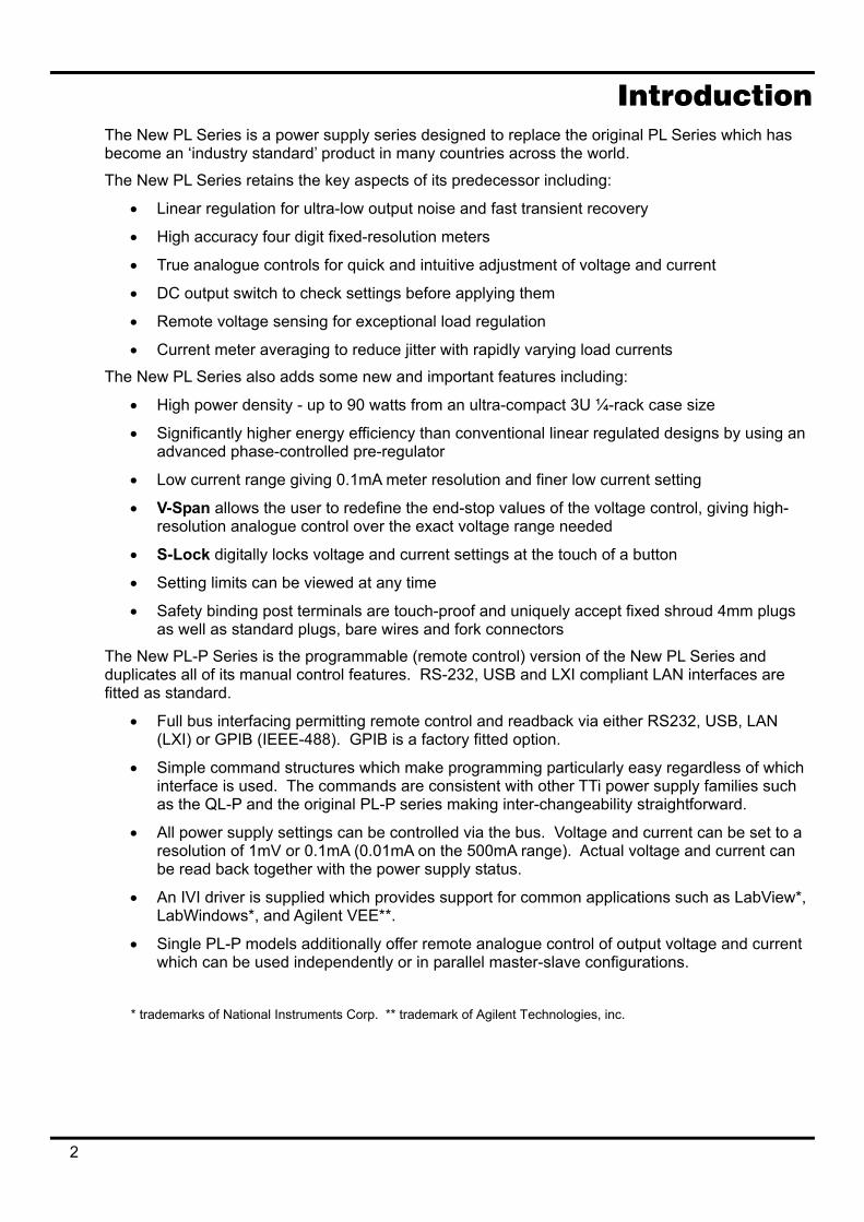
Introduction The New PL Series is a power supply series designed to replace the original PL Series which has become an ‘industry standard’ product in many countries across the world.
The New PL Series retains the key aspects of its predecessor including:
• Linear regulation for ultra-low output noise and fast transient recovery
• High accuracy four digit fixed-resolution meters
• True analogue controls for quick and intuitive adjustment of voltage and current
• DC output switch to check settings before applying them
• Remote voltage sensing for exceptional load regulation
• Current meter averaging to reduce jitter with rapidly varying load currents
The New PL Series also adds some new and important features including:
• High power density - up to 90 watts from an ultra-compact 3U ¼-rack case size
• Significantly higher energy efficiency than conventional linear regulated designs by using an advanced phase-controlled pre-regulator
• Low current range giving 0.1mA meter resolution and finer low current setting
• V-Span allows the user to redefine the end-stop values of the voltage control, giving high-resolution analogue control over the exact voltage range needed
• S-Lock digitally locks voltage and current settings at the touch of a button
• Setting limits can be viewed at any time
• Safety binding post terminals are touch-proof and uniquely accept fixed shroud 4mm plugs as well as standard plugs, bare wires and fork connectors
The New PL-P Series is the programmable (remote control) version of the New PL Series and duplicates all of its manual control features. RS-232, USB and LXI compliant LAN interfaces are fitted as standard.
• Full bus interfacing permitting remote control and readback via either RS232, USB, LAN (LXI) or GPIB (IEEE-488). GPIB is a factory fitted option.
• Simple command structures which make programming particularly easy regardless of which interface is used. The commands are consistent with other TTi power supply families such as the QL-P and the original PL-P series making inter-changeability straightforward.
• All power supply settings can be controlled via the bus. Voltage and current can be set to a resolution of 1mV or 0.1mA (0.01mA on the 500mA range). Actual voltage and current can be read back together with the power supply status.
• An IVI driver is supplied which provides support for common applications such as LabView*, LabWindows*, and Agilent VEE**.
• Single PL-P models additionally offer remote analogue control of output voltage and current which can be used independently or in parallel master-slave configurations.
* trademarks of National Instruments Corp. ** trademark of Agilent Technologies, inc.
2
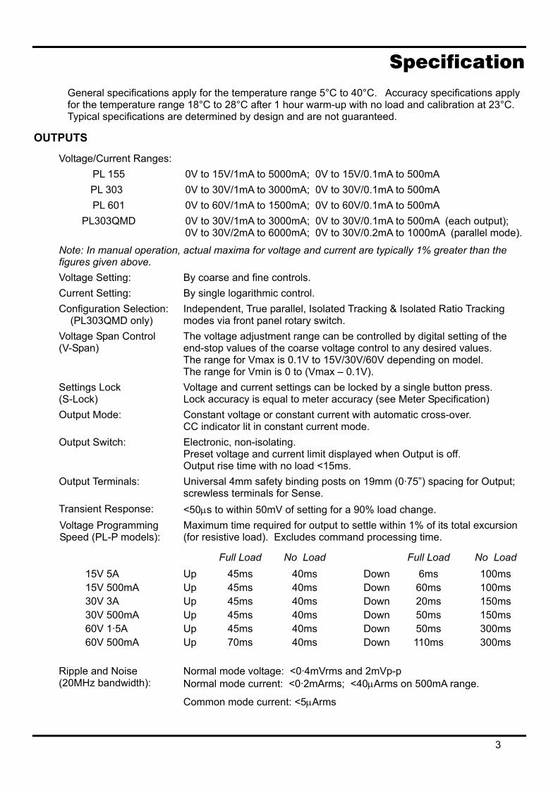
Specification General specifications apply for the temperature range 5°C to 40°C. Accuracy specifications apply for the temperature range 18°C to 28°C after 1 hour warm-up with no load and calibration at 23°C. Typical specifications are determined by design and are not guaranteed.
OUTPUTS
Voltage/Current Ranges: PL 155 0V to 15V/1mA to 5000mA; 0V to 15V/0.1mA to 500mA PL 303 0V to 30V/1mA to 3000mA; 0V to 30V/0.1mA to 500mA PL 601 0V to 60V/1mA to 1500mA; 0V to 60V/0.1mA to 500mA PL303QMD 0V to 30V/1mA to 3000mA; 0V to 30V/0.1mA to 500mA (each output);
0V to 30V/2mA to 6000mA; 0V to 30V/0.2mA to 1000mA (parallel mode).
Note: In manual operation, actual maxima for voltage and current are typically 1% greater than the figures given above. Voltage Setting: By coarse and fine controls. Current Setting: By single logarithmic control. Configuration Selection: (PL303QMD only)
Independent, True parallel, Isolated Tracking & Isolated Ratio Tracking modes via front panel rotary switch.
Voltage Span Control (V-Span)
The voltage adjustment range can be controlled by digital setting of the end-stop values of the coarse voltage control to any desired values. The range for Vmax is 0.1V to 15V/30V/60V depending on model. The range for Vmin is 0 to (Vmax – 0.1V).
Settings Lock (S-Lock)
Voltage and current settings can be locked by a single button press. Lock accuracy is equal to meter accuracy (see Meter Specification)
Output Mode: Constant voltage or constant current with automatic cross-over. CC indicator lit in constant current mode.
Output Switch: Electronic, non-isolating. Preset voltage and current limit displayed when Output is off. Output rise time with no load <15ms.
Output Terminals: Universal 4mm safety binding posts on 19mm (0·75”) spacing for Output; screwless terminals for Sense.
Transient Response: <50µs to within 50mV of setting for a 90% load change. Voltage Programming Speed (PL-P models):
Maximum time required for output to settle within 1% of its total excursion (for resistive load). Excludes command processing time.
Full Load No Load Full Load No Load 15V 5A 15V 500mA 30V 3A 30V 500mA 60V 1·5A 60V 500mA
Up Up Up Up Up Up
45ms 45ms 45ms 45ms 45ms 70ms
40ms 40ms 40ms 40ms 40ms 40ms
DownDownDownDownDownDown
6ms 60ms 20ms 50ms 50ms 110ms
100ms 100ms 150ms 150ms 300ms 300ms
Ripple and Noise (20MHz bandwidth):
Normal mode voltage: <0·4mVrms and 2mVp-p Normal mode current: <0·2mArms; <40µArms on 500mA range.
Common mode current: <5µArms
3
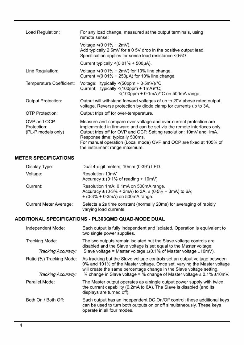
Load Regulation: For any load change, measured at the output terminals, using remote sense:
Voltage <(0·01% + 2mV). Add typically 2·5mV for a 0·5V drop in the positive output lead. Specification applies for sense lead resistance <0·5Ω.
Current typically <(0·01% + 500µA).
Line Regulation: Voltage <(0·01% + 2mV) for 10% line change. Current <(0·01% + 250µA) for 10% line change.
Temperature Coefficient: Voltage: typically <(50ppm + 0·5mV)/°C Current: typically <(100ppm + 1mA)/°C; <(100ppm + 0·1mA)/°C on 500mA range.
Output Protection: Output will withstand forward voltages of up to 20V above rated output voltage. Reverse protection by diode clamp for currents up to 3A.
OTP Protection: Output trips off for over-temperature.
OVP and OCP Protection: (PL-P models only)
Measure-and-compare over-voltage and over-current protection are implemented in firmware and can be set via the remote interfaces only. Output trips off for OVP and OCP. Setting resolution: 10mV and 1mA. Response time: typically 500ms. For manual operation (Local mode) OVP and OCP are fixed at 105% of the instrument range maximum.
METER SPECIFICATIONS Display Type: Dual 4-digit meters, 10mm (0·39") LED. Voltage: Resolution 10mV
Accuracy ± (0·1% of reading + 10mV) Current: Resolution 1mA; 0·1mA on 500mA range.
Accuracy ± (0·3% + 3mA) to 3A, ± (0·5% + 3mA) to 6A; ± (0·3% + 0·3mA) on 500mA range.
Current Meter Average: Selects a 2s time constant (normally 20ms) for averaging of rapidly varying load currents.
ADDITIONAL SPECIFICATIONS - PL303QMD QUAD-MODE DUAL
Independent Mode: Each output is fully independent and isolated. Operation is equivalent to two single power supplies.
Tracking Mode: Tracking Accuracy:
The two outputs remain isolated but the Slave voltage controls are disabled and the Slave voltage is set equal to the Master voltage. Slave voltage = Master voltage ±(0.1% of Master voltage ±10mV).
Ratio (%) Tracking Mode: Tracking Accuracy:
As tracking but the Slave voltage controls set an output voltage between 0% and 101% of the Master voltage. Once set, varying the Master voltage will create the same percentage change in the Slave voltage setting. % change in Slave voltage = % change of Master voltage ± 0.1% ±10mV.
Parallel Mode: The Master output operates as a single output power supply with twice the current capability (0.2mA to 6A). The Slave is disabled (and its displays are turned off).
Both On / Both Off: Each output has an independent DC On/Off control; these additional keys can be used to turn both outputs on or off simultaneously. These keys operate in all four modes.
4
ANALOGUE REMOTE CONTROL (Single PL-P models only) Non-isolated inputs and outputs to set voltage and current limit
Control input and output scaling:
Rear panel control inputs (CV and CC) permit external 0V to 5V or 0 to10V signals to set 0 to 100% of rated output voltage and current. Set values of 0 to 100% of rated output voltage and current generate 0 to 5V signals at the rear panel Vout and Iout outputs. These signals are referenced to the positive output.
Control input accuracy: Voltage: 0.3% ±10mV. Input impedance 100kΩ; protected to 60V.
Current: 0.5% ±5mA. Input impedance 64kΩ; protected to 60V. Control output accuracy:
Voltage: 0.3% ±10mV Current: 0.5% ±5mA. Output impedance: 125Ω; output short-circuit protected.
Remote Off: Rear panel socket allows a switch closure or logic low to turn output off.
DIGITAL INTERFACES (PL-P models only) Full digital remote control facilities are available through the RS232, USB, LAN and GPIB interfaces.
Voltage Setting: Resolution 1mV, Accuracy ± (0·05% + 5mV) Voltage Readback: Resolution 1mV, Accuracy ± (0·1% + 5mV) Current Setting and Current Readback:
Resolution 0.1mA; 0.01mA on 500mA range. Accuracy ± (0·3% + 3mA) to 3A, ± (0·5% + 3mA) to 6A; ± (0·3% + 0·3mA) on 500mA range.
RS232: Standard 9-pin D-connector. Baud rate 9600. GPIB (optional): Conforming with IEEE488.1 and IEEE488.2 USB: Standard USB 2.0 hardware connection. Operates as a virtual COM port. LAN: Ethernet 100/10base-T hardware connection. LXI V1.2, Class C compliant. Remote Command Processing Time:
Typically <25ms between receiving the command terminator for a step voltage change at the instrument and the output voltage beginning to change.
GENERAL AC Input: 230V AC or 115V AC ± 10%, 50/60Hz. Installation Category II Power Consumption: Single: 280VA max. Dual: 560VA max. Operating Range: +5ºC to +40ºC, 20% to 80% RH Storage Range: −40ºC to + 70ºC Environmental: Indoor use at altitudes up to 2000m, Pollution Degree 2. Cooling: Intelligent variable-speed low noise fan assists convection. Over-
temperature trip shuts down output if internal temperatures exceed predetermined thresholds.
Safety: Complies with EN61010−1 EMC: Complies with EN61326 Size: Single: 107mm x 131mm (¼ rack 3U) x 288mm L (PL-P: 343mm L),
excluding feet, knobs and terminals. Dual: 214mm x 131mm (½ rack 3U) x 288mm L, excluding feet, knobs and terminals.
Weight: Single: 4·5kg (PL-P: 4.9kg). Dual: 8.5kg.
5
EC Declaration of Conformity
We Thurlby Thandar Instruments Ltd Glebe Road Huntingdon Cambridgeshire PE29 7DR England
declare that the
PL & PL-P Series Precision Power Supplies with GPIB Option
meet the intent of the EMC Directive 2004/108/EC and the Low Voltage Directive 2006/95/EC. Compliance was demonstrated by conformance to the following specifications which have been listed in the Official Journal of the European Communities.
EMC Emissions: a) EN61326-1 (2006) Radiated, Class B
b) EN61326-1 (2006) Conducted, Class B
c) EN61326-1 (2006) Harmonics, referring to EN61000-3-2 (2006)
Immunity: EN61326-1 (2006) Immunity Table 1, referring to:
a) EN61000-4-2 (1995) Electrostatic Discharge
b) EN61000-4-3 (2006) Electromagnetic Field
c) EN61000-4-11 (2004) Voltage Interrupt
d) EN61000-4-4 (2004) Fast Transient
e) EN61000-4-5 (2006) Surge
f) EN61000-4-6 (2007) Conducted RF
Performance levels achieved are detailed in the user manual.
Safety
EN61010-1 Installation Category II, Pollution Degree 2.
CHRIS WILDING TECHNICAL DIRECTOR
2 May 2009
6
EMC This instrument has been designed to meet the requirements of the EMC Directive 2004/108/EC. Compliance was demonstrated by meeting the test limits of the following standards:
Emissions EN61326-1 (2006) EMC product standard for Electrical Equipment for Measurement, Control and Laboratory Use. Test limits used were:
a) Radiated: Class B b) Conducted: Class B c) Harmonics: EN61000-3-2 (2006) Class A; the instrument is Class A by product category.
Immunity EN61326-1 (2006) EMC product standard for Electrical Equipment for Measurement, Control and Laboratory Use.
Test methods, limits and performance achieved are shown below (requirement shown in brackets):
a) EN61000-4-2 (1995) Electrostatic Discharge : 4kV air, 4kV contact, Performance A (B). b) EN61000-4-3 (2006) Electromagnetic Field:
3V/m, 80% AM at 1kHz, 80MHz – 1GHz: Performance A (A) and 1.4GHz to 2GHz: Performance A (A); 1V/m, 2.0GHz to 2.7GHz: Performance A (A).
c) EN61000-4-11 (2004) Voltage Interrupt: ½ cycle, 0%: Performance A (B); 1 cycle, 0%: Performance B (B); 25 cycles, 70% and 250 cycles, 0%: Performance B* (C). * Output status at power-up must be set to be same as at last power-down, otherwise Performance C.
d) EN61000-4-4 (2004) Fast Transient, 1kV peak (AC line only; DC Output connections <3m, therefore not tested†), Performance B (B).
e) EN61000-4-5 (2006) Surge, 0·5kV (line to line), 1kV (line to ground), Performance A (B). f) EN61000-4-6 (2007) Conducted RF, 3V, 80% AM at 1kHz (AC line only; DC Output connections <3m, therefore not tested†), Performance A (A).
†signal lines were not tested on the basis that typical use will be with connections <3m, for which there is no test requirement. Immunity performance with connections >3m is not guaranteed.
According to EN61326-1 the definitions of performance criteria are: Performance criterion A: ‘During test normal performance within the specification limits.’ Performance criterion B: ‘During test, temporary degradation, or loss of function or performance which is self-recovering’. Performance criterion C: ‘During test, temporary degradation, or loss of function or performance which requires operator intervention or system reset occurs.’ Where Performance B is stated it is because DC Output regulation, or V & I measurement accuracy, may deviate beyond Specification limits under the test conditions. However, the possible deviations are still small and unlikely to be a problem in practice.
Note that if operation in a high RF field is unavoidable it is good practice to connect the PSU to the target system using screened leads which have been passed (together) through an absorbing ferrite sleeve fitted close to the PSU terminals.
Cautions To ensure continued compliance with the EMC directive observe the following precautions: a) after opening the case for any reason ensure that all signal and ground connections are
remade correctly and that case screws are correctly refitted and tightened. b) In the event of part replacement becoming necessary, only use components of an identical
type, see the Service Manual.
7
Safety This instrument is a Safety Class I instrument according to IEC classification and has been designed to meet the requirements of EN61010-1 (Safety Requirements for Electrical Equipment for Measurement, Control and Laboratory Use). It is an Installation Category II instrument intended for operation from a normal single phase supply.
This instrument has been tested in accordance with EN61010-1 and has been supplied in a safe condition. This instruction manual contains some information and warnings which have to be followed by the user to ensure safe operation and to retain the instrument in a safe condition.
This instrument has been designed for indoor use in a Pollution Degree 2 environment in the temperature range 5°C to 40°C, 20% - 80% RH (non-condensing). It may occasionally be subjected to temperatures between +5°C and –10°C without degradation of its safety. Do not operate while condensation is present.
Use of this instrument in a manner not specified by these instructions may impair the safety protection provided. Do not operate the instrument outside its rated supply voltages or environmental range.
WARNING! THIS INSTRUMENT MUST BE EARTHED Any interruption of the mains earth conductor inside or outside the instrument will make the instrument dangerous. Intentional interruption is prohibited. The protective action must not be negated by the use of an extension cord without a protective conductor.
When the instrument is connected to its supply, terminals may be live and opening the covers or removal of parts (except those to which access can be gained by hand) is likely to expose live parts. The apparatus shall be disconnected from all voltage sources before it is opened for any adjustment, replacement, maintenance or repair.
Capacitors inside the power supply may still be charged even if the power supply has been disconnected from all voltage sources but will be safely discharged about 10 minutes after switching off power.
Any adjustment, maintenance and repair of the opened instrument under voltage shall be avoided as far as possible and, if inevitable, shall be carried out only by a skilled person who is aware of the hazard involved.
If the instrument is clearly defective, has been subject to mechanical damage, excessive moisture or chemical corrosion the safety protection may be impaired and the apparatus should be withdrawn from use and returned for checking and repair.
Make sure that only fuses with the required rated current and of the specified type are used for replacement. The use of makeshift fuses and the short-circuiting of fuse holders is prohibited.
Do not wet the instrument when cleaning it.
The following symbols are used on the instrument and in this manual:-
Caution - refer to the accompanying documentation, incorrect operation may damage the instrument.
Earth (ground) terminal.
mains supply OFF.
l mains supply ON.
alternating current (ac)
direct current (dc)
8
Installation Mains Operating Voltage
Check that the instrument operating voltage marked on the rear panel is suitable for the local supply. Should it be necessary to change the operating voltage, proceed as follows:
1. Ensure that the instrument is disconnected from the AC supply.
2. Remove the plastic push-rivets at each side edge of the top cover. Use the blade of a small screwdriver to first ease out the rivet head and then fully remove the rivet body. Remove the two rear panel screws securing the top cover; slide the cover back and lift off.
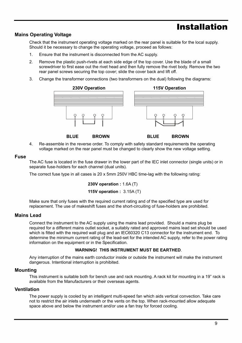
3. Change the transformer connections (two transformers on the dual) following the diagrams:
230V Operation 115V Operation
BLUE BROWN BLUE BROWN 4. Re-assemble in the reverse order. To comply with safety standard requirements the operating
voltage marked on the rear panel must be changed to clearly show the new voltage setting.
Fuse The AC fuse is located in the fuse drawer in the lower part of the IEC inlet connector (single units) or in separate fuse-holders for each channel (dual units).
The correct fuse type in all cases is 20 x 5mm 250V HBC time-lag with the following rating:
230V operation : 1.6A (T)
115V operation : 3.15A (T)
Make sure that only fuses with the required current rating and of the specified type are used for replacement. The use of makeshift fuses and the short-circuiting of fuse-holders are prohibited.
Mains Lead Connect the instrument to the AC supply using the mains lead provided. Should a mains plug be required for a different mains outlet socket, a suitably rated and approved mains lead set should be used which is fitted with the required wall plug and an IEC60320 C13 connector for the instrument end. To determine the minimum current rating of the lead-set for the intended AC supply, refer to the power rating information on the equipment or in the Specification.
WARNING! THIS INSTRUMENT MUST BE EARTHED.
Any interruption of the mains earth conductor inside or outside the instrument will make the instrument dangerous. Intentional interruption is prohibited.
Mounting This instrument is suitable both for bench use and rack mounting. A rack kit for mounting in a 19” rack is available from the Manufacturers or their overseas agents.
Ventilation The power supply is cooled by an intelligent multi-speed fan which aids vertical convection. Take care not to restrict the air inlets underneath or the vents on the top. When rack-mounted allow adequate space above and below the instrument and/or use a fan tray for forced cooling.
9
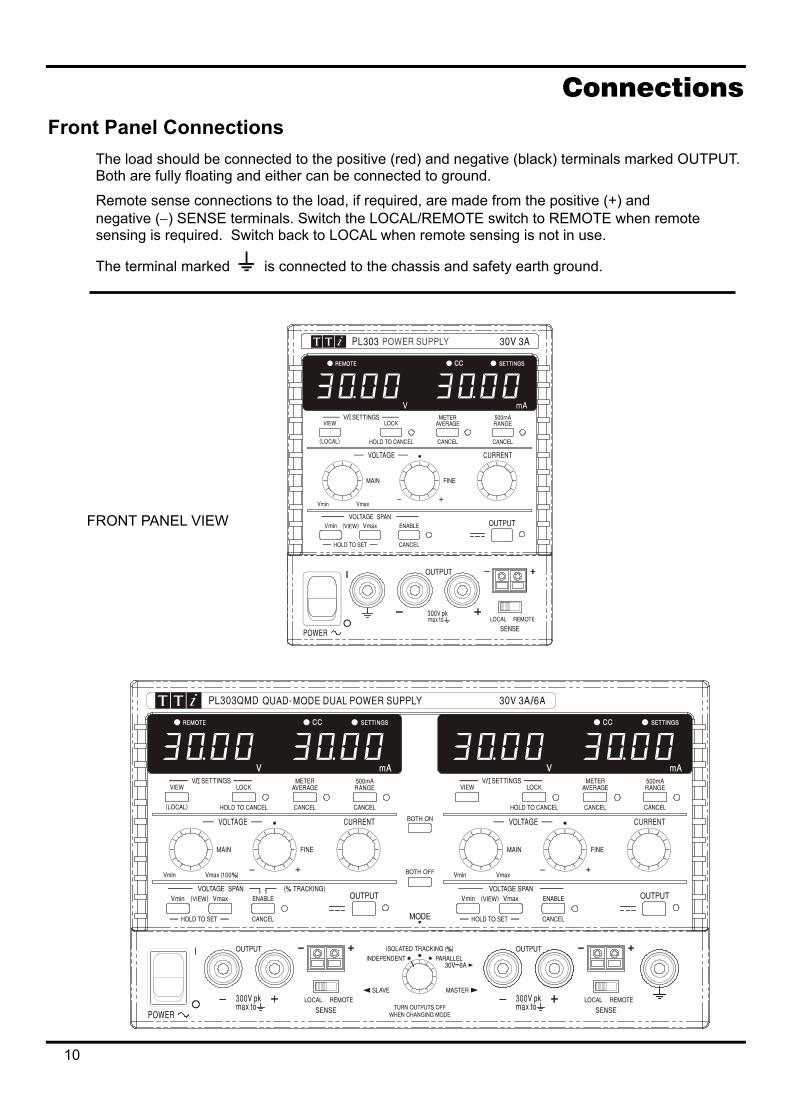
Connections Front Panel Connections
The load should be connected to the positive (red) and negative (black) terminals marked OUTPUT. Both are fully floating and either can be connected to ground.
Remote sense connections to the load, if required, are made from the positive (+) and negative (−) SENSE terminals. Switch the LOCAL/REMOTE switch to REMOTE when remote sensing is required. Switch back to LOCAL when remote sensing is not in use.
The terminal marked is connected to the chassis and safety earth ground.
10
FRONT PANEL VIEW
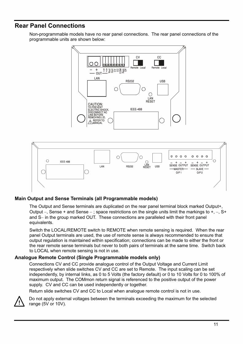
Rear Panel Connections Non-programmable models have no rear panel connections. The rear panel connections of the programmable units are shown below:
Main Output and Sense Terminals (all Programmable models)
The Output and Sense terminals are duplicated on the rear panel terminal block marked Output+, Output −, Sense + and Sense − ; space restrictions on the single units limit the markings to +, −, S+ and S− in the group marked OUT. These connections are paralleled with their front panel equivalents.
Switch the LOCAL/REMOTE switch to REMOTE when remote sensing is required. When the rear panel Output terminals are used, the use of remote sense is always recommended to ensure that output regulation is maintained within specification; connections can be made to either the front or the rear remote sense terminals but never to both pairs of terminals at the same time. Switch back to LOCAL when remote sensing is not in use.
Analogue Remote Control (Single Programmable models only) Connections CV and CC provide analogue control of the Output Voltage and Current Limit respectively when slide switches CV and CC are set to Remote. The input scaling can be set independently, by internal links, as 0 to 5 Volts (the factory default) or 0 to 10 Volts for 0 to 100% of maximum output. The COMmon return signal is referenced to the positive output of the power supply. CV and CC can be used independently or together. Return slide switches CV and CC to Local when analogue remote control is not in use.
Do not apply external voltages between the terminals exceeding the maximum for the selected range (5V or 10V).
11
Analogue Out (Single Programmable models only) Connections VOUT and IOUT provide analogue outputs scaled to the set output voltage and set current limit respectively. The scaling is fixed at 0 to 5 Volts for 0 to 100% of maximum output. VOUT and IOUT are always present on the terminals, whether the instrument is under local or remote control. The COMMON return signal is referenced to the positive output of the power supply.
Do not apply external voltages to these terminals.
Remote On/Off (Single Programmable models only) A switch closure or logic low between connections Rem Off and COM will turn off the output. The COM return signal is referenced to the positive output of the power supply.
Do not apply external voltages to these terminals.
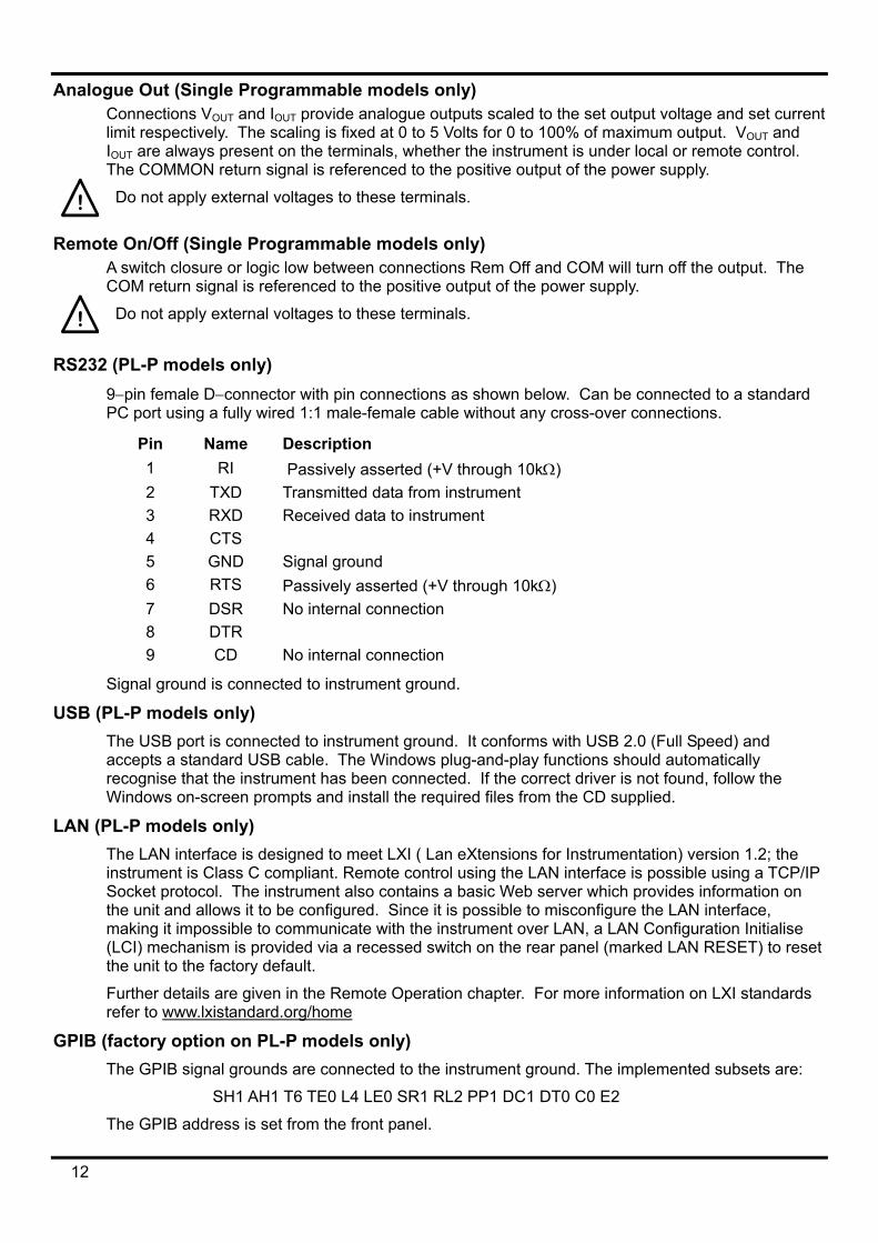
RS232 (PL-P models only) 9−pin female D−connector with pin connections as shown below. Can be connected to a standard PC port using a fully wired 1:1 male-female cable without any cross-over connections.
Pin Name Description 1 RI Passively asserted (+V through 10kΩ) 2 TXD Transmitted data from instrument 3 RXD Received data to instrument 4 CTS 5 GND Signal ground 6 RTS Passively asserted (+V through 10kΩ) 7 DSR No internal connection 8 DTR 9 CD No internal connection
Signal ground is connected to instrument ground.
USB (PL-P models only) The USB port is connected to instrument ground. It conforms with USB 2.0 (Full Speed) and accepts a standard USB cable. The Windows plug-and-play functions should automatically recognise that the instrument has been connected. If the correct driver is not found, follow the Windows on-screen prompts and install the required files from the CD supplied.
LAN (PL-P models only) The LAN interface is designed to meet LXI ( Lan eXtensions for Instrumentation) version 1.2; the instrument is Class C compliant. Remote control using the LAN interface is possible using a TCP/IP Socket protocol. The instrument also contains a basic Web server which provides information on the unit and allows it to be configured. Since it is possible to misconfigure the LAN interface, making it impossible to communicate with the instrument over LAN, a LAN Configuration Initialise (LCI) mechanism is provided via a recessed switch on the rear panel (marked LAN RESET) to reset the unit to the factory default.
Further details are given in the Remote Operation chapter. For more information on LXI standards refer to www.lxistandard.org/home
GPIB (factory option on PL-P models only) The GPIB signal grounds are connected to the instrument ground. The implemented subsets are:
SH1 AH1 T6 TE0 L4 LE0 SR1 RL2 PP1 DC1 DT0 C0 E2
The GPIB address is set from the front panel.
12
Manual Operation In this operating manual, front panel keys, controls and sockets are shown in capitals, e.g. CURRENT, OUTPUT, LOCK. Messages displayed on the 7-segment LEDs are shown in a different type-font, e.g. turn oFF, OtP trip. The additional features of the Quad-mode Dual instrument are described together at the end of this chapter.
Switching On and Power-On Conditions The POWER switch is located at the bottom left of the front panel. When the POWER switch is turned on ( l ) the right hand meter briefly indicates the firmware revision before the display shows Volts and Amps.
For programmable PL-P models the default display sequence at power on is different: the right hand meter briefly indicates the instrument firmware revision followed by the interface firmware revision ( IF shows in the left hand meter) before the display shows Volts and Amps. If, after a few seconds, no physical LAN connection is found, the instrument's display will flash alternately between the normal voltage and current values and the message LAn Err, for the next 10 seconds. Indication of no LAN connection at power on is an essential LXI compliance requirement but can be disabled by the 'NOLANOK 1' command over any interface, see the LAN Error paragraph in the Remote Interface Operation section for further details. This change of power on setting is retained until reversed by a 'NOLANOK 0' command or by the use of the rear panel LAN RESET switch to restore the factory default LAN setting, see the LAN paragraph in the Remote Interface Operation section.
Note that the display messages do not affect the operation of the power supply itself.
At power on, the factory default setting is for the output to be off. The preset output volts and current will be determined by the present control settings and shown in the display. All other settings will be the sam
Repeating the procedure will change the setting back to the previous state. Note that the power-on status of the two outputs of the dual supply need to be set individually.
Output Control Setting Up the Output
With the POWER switch on and the OUTPUT off the output voltage and current limit can be accurately preset using the VOLTAGE and CURRENT controls; the left-hand meter shows the set voltage, the right-hand meter shows the set maximum current and the SETTINGS indicator is lit.
When the output switch is switched on, the OUTPUT indicator lights; the left-hand meter now shows the actual voltage and the right-hand meter the actual load current.
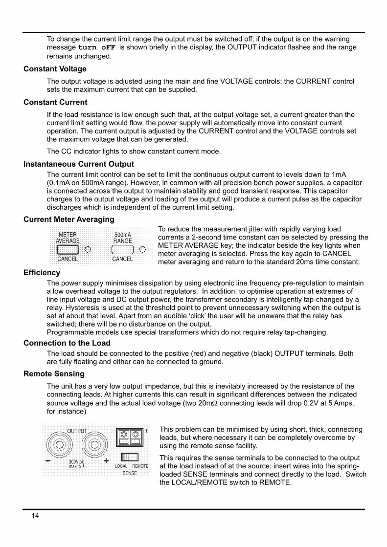
The upper limit of the CURRENT control can be switched between the maximum for this model and 500mA with alternate presses of the 500mA RANGE key to give finer current limit setting and measurement resolution (0.1mA up to 500mA); the indicator beside the key is lit when the 500mA range is selected.
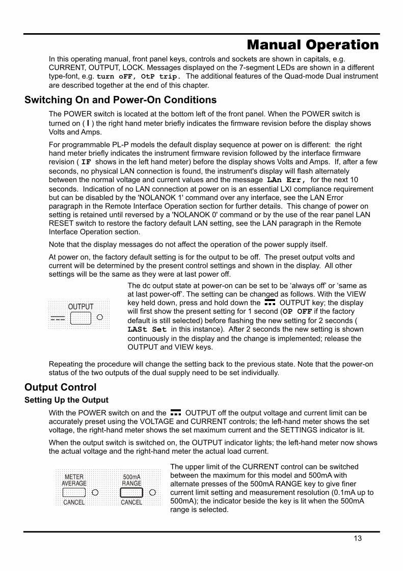
e as they were at last power off. The dc output state at power-on can be set to be ‘always off’ or ‘same as at last power-off’. The setting can be changed as follows. With the VIEW key held down, press and hold down the OUTPUT key; the display will first show the present setting for 1 second (OP OFF if the factory default is still selected) before flashing the new setting for 2 seconds ( LASt Set in this instance). After 2 seconds the new setting is shown continuously in the display and the change is implemented; release the OUTPUT and VIEW keys.
13
To change the current limit range the output must be switched off; if the output is on the warning message turn oFF is shown briefly in the display, the OUTPUT indicator flashes and the range remains unchanged.
Constant Voltage The output voltage is adjusted using the main and fine VOLTAGE controls; the CURRENT control sets the maximum current that can be supplied.
Constant Current If the load resistance is low enough such that, at the output voltage set, a current greater than the current limit setting would flow, the power supply will automatically move into constant current operation. The current output is adjusted by the CURRENT control and the VOLTAGE controls set the maximum voltage that can be generated.
The CC indicator lights to show constant current mode.
Instantaneous Current Output The current limit control can be set to limit the continuous output current to levels down to 1mA (0.1mA on 500mA range). However, in common with all precision bench power supplies, a capacitor is connected across the output to maintain stability and good transient response. This capacitor charges to the output voltage and loading of the output will produce a current pulse as the capacitor discharges which is independent of the current limit setting.
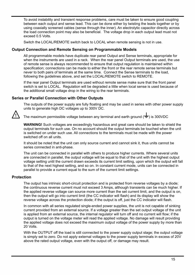
Current Meter Averaging To reduce the measurement jitter with rapidly varying load currents a 2-second time constant can be selected by pressing theMETER AVERAGE key; the indicator beside the key lights when meter averaging is selected. Press the key again to CANCEL meter averaging and return to the standard 20ms time constant.
Efficiency The power supply minimises dissipation by using electronic line frequency pre-regulation to maintain a low overhead voltage to the output regulators. In addition, to optimise operation at extremes of line input voltage and DC output power, the transformer secondary is intelligently tap-changed by a relay. Hysteresis is used at the threshold point to prevent unnecessary switching when the output is set at about that level. Apart from an audible ‘click’ the user will be unaware that the relay has switched; there will be no disturbance on the output. Programmable models use special transformers which do not require relay tap-changing.
Connection to the Load The load should be connected to the positive (red) and negative (black) OUTPUT terminals. Both are fully floating and either can be connected to ground.
Remote Sensing The unit has a very low output impedance, but this is inevitably increased by the resistance of the connecting leads. At higher currents this can result in significant differences between the indicated source voltage and the actual load voltage (two 20mΩ connecting leads will drop 0.2V at 5 Amps, for instance)
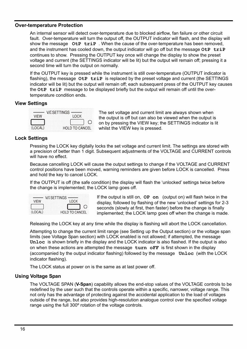
This problem can be minimised by using short, thick, connecting leads, but where necessary it can be completely overcome by using the remote sense facility.
This requires the sense terminals to be connected to the output at the load instead of at the source; insert wires into the spring-loaded SENSE terminals and connect directly to the load. Switch the LOCAL/REMOTE switch to REMOTE.
.
14
To avoid instability and transient response problems, care must be taken to ensure good coupling between each output and sense lead. This can be done either by twisting the leads together or by using coaxially screened cables (sense through the inner). An electrolytic capacitor directly across the load connection point may also be beneficial. The voltage drop in each output lead must not exceed 0.5 Volts.
Switch the LOCAL/REMOTE switch back to LOCAL when remote sensing is not in use.
Output Connection and Remote Sensing on Programmable Models All programmable models have duplicate rear panel Output and Sense terminals, appropriate for when the instruments are used in a rack. When the rear panel Output terminals are used, the use of remote sense is always recommended to ensure that output regulation is maintained within specification; connections can be made to either the front or the rear remote sense terminals but never to both pairs of terminals at the same time. Connect the Sense terminals to the load, following the guidelines above, and set the LOCAL/REMOTE switch to REMOTE.
If the rear panel Output terminals are used without remote sense make sure that the front panel switch is set to LOCAL. Regulation will be degraded a little when local sense is used because of the additional small voltage drop in the wiring to the rear terminals.
Series or Parallel Connection with Other Outputs The outputs of the power supply are fully floating and may be used in series with other power supply units to generate high DC voltages up to 300V DC.
The maximum permissible voltage between any terminal and earth ground ( ) is 300VDC
WARNING! Such voltages are exceedingly hazardous and great care should be taken to shield the output terminals for such use. On no account should the output terminals be touched when the unit is switched on under such use. All connections to the terminals must be made with the power switched off on all units.
It should be noted that the unit can only source current and cannot sink it, thus units cannot be series connected in anti-phase.
The unit can be connected in parallel with others to produce higher currents. Where several units are connected in parallel, the output voltage will be equal to that of the unit with the highest output voltage setting until the current drawn exceeds its current limit setting, upon which the output will fall to that of the next highest setting, and so on. In constant current mode, units can be connected in parallel to provide a current equal to the sum of the current limit settings.
Protection The output has intrinsic short-circuit protection and is protected from reverse voltages by a diode; the continuous reverse current must not exceed 3 Amps, although transients can be much higher. If the applied reverse voltage can source more current than the set current limit, and the output is on, then the output will go into current limit (the CC indicator will flash) and its display will show the reverse voltage across the protection diode; if the output is off, just the CC indicator will flash.
In common with all series regulated single-ended power supplies, the unit is not capable of sinking current provided from an external source. If a voltage greater than the set output voltage of the unit is applied from an external source, the internal regulator will turn off and no current will flow; if the output is turned on the voltage meter will read the applied voltage. No damage will result providing the applied voltage does not exceed the maximum output voltage of the power supply by more than 20 Volts.
With the OUTPUT off the load is still connected to the power supply output stage; the output voltage is simply set to zero. Do not apply external voltages to the power supply terminals in excess of 20V above the rated output voltage, even with the output off, or damage may result.
15
Over-temperature Protection An internal sensor will detect over-temperature due to blocked airflow, fan failure or other circuit fault. Over-temperature will turn the output off, the OUTPUT indicator will flash, and the display will show the message OtP triP . When the cause of the over-temperature has been removed, and the instrument has cooled down, the output indicator will go off but the message OtP triP continues to show. Pressing the OUTPUT key once will change the display to show the preset voltage and current (the SETTINGS indicator will be lit) but the output will remain off; pressing it a second time will turn the output on normally.
If the OUTPUT key is pressed while the instrument is still over-temperature (OUTPUT indicator is flashing), the message OtP triP is replaced by the preset voltage and current (the SETTINGS indicator will be lit) but the output will remain off; each subsequent press of the OUTPUT key causes the OtP triP message to be displayed briefly but the output will remain off until the over-temperature condition ends.
View ettings
Lock Settings
Pressing the LOCK key digitally la precision of better than 1 digit. will have no effect.
Because cancelling LOCK will cacontrol positions have been moveand hold the key to cancel LOCK
If the OUTPUT is off (the safe cothe change is implemented; the L
Releasing the LOCK key at any t
Attempting to change the currentlimits (see Voltage Span section) Unloc is shown briefly in the dion when these actions are attem(accompanied by the output indicindicator flashing).
The LOCK status at power on is t
Using Voltage Span The VOLTAGE SPAN (V-Span) credefined by the user such that thnot only has the advantage of prooutside of the range, but also prorange using the full 300º rotation
16
The set voltage and current limit are always shown when the output is off but can also be viewed when the output is on by pressing the VIEW key; the SETTINGS indicator is lit whilst the VIEW key is pressed.
S
ocks the set voltage and current limit. The settings are stored with Subsequent adjustments of the VOLTAGE and CURRENT controls
use the output settings to change if the VOLTAGE and CURRENT d, warning reminders are given before LOCK is cancelled. Press
.
ndition) the display will flash the ‘unlocked’ settings twice before OCK lamp goes off.
If the output is still on, OP on (output on) will flash twice in the display, followed by flashing of the new ‘unlocked’ settings for 2-3 seconds (slowly at first, then faster) before the change is finally implemented; the LOCK lamp goes off when the change is made.
ime while the display is flashing will abort the LOCK cancellation.
limit range (see Setting up the Output section) or the voltage span with LOCK enabled is not allowed; if attempted, the message splay and the LOCK indicator is also flashed. If the output is also pted the message turn oFF is first shown in the display ator flashing) followed by the message Unloc (with the LOCK
he same as at last power off.
apability allows the end-stop values of the VOLTAGE controls to be e controls operate within a specific, narrower, voltage range. This tecting against the accidental application to the load of voltages vides high-resolution analogue control over the specified voltage of the voltage controls.
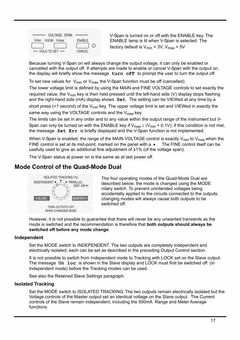
Because turning V-Span on will always ccancelled with the output off. If attempts the display will briefly show the message
To set new values for Vmin or Vmax the VThe lower voltage limit is defined by usinrequired value; the Vmin key is then heldand the right-hand side (mA) display shoshort press (<1 second) of the Vmin key. same way using the VOLTAGE controls The limits can be set in any order and toSpan can only be turned on with the ENAthe message Set Err is briefly displa
When V-Span is enabled, the range of thFINE control is set at its mid-point, markusefully used to give an additional fine a
The V-Span status at power on is the sa
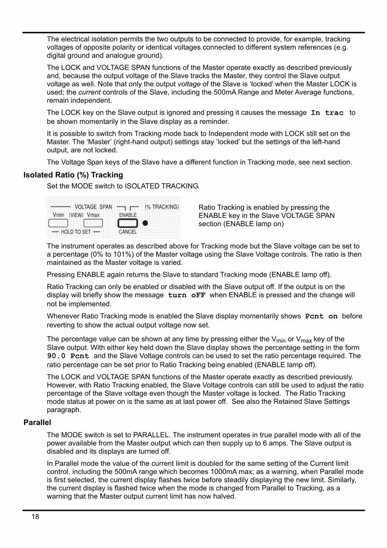
Mode Control of the Quad-Mode The
desrotaaccchaswi
However, it is not possible to guarantee mode is switched and the recommendatswitched off before any mode change
Independent Set the MODE switch to INDEPENDENTelectrically isolated; each can be set as
It is not possible to switch from IndependThe message Un loc is shown in theIndependent mode) before the Tracking
See also the Retained Slave Settings pa
Isolated Tracking Set the MODE switch to ISOLATED TRAVoltage controls of the Master output setcontrols of the Slave remain independenfunctions.
V-Span is turned on or off with the ENABLE key. The ENABLE lamp is lit when V-Span is selected. The factory default is Vmin = 3V, Vmax = 5V
hange the output voltage, it can only be enabled or are made to enable or cancel V-Span with the output on, turn oFF to prompt the user to turn the output off.
-Span function must be off (cancelled). g the MAIN and FINE VOLTAGE controls to set exactly the pressed until the left-hand side (V) display stops flashing ws Set. The setting can be VIEWed at any time by a The upper voltage limit is set and VIEWed in exactly the and the Vmax key. any value within the output range of the instrument but V-BLE key if Vmax ≥ (Vmin + 0.1V); if this condition is not met, yed and the V-Span function is not implemented.
e MAIN VOLTAGE control is exactly Vmin to Vmax when the ed on the panel with a • . The FINE control itself can be djustment of ±1% (of the voltage span).
me as at last power off.
Dual
four operating modes of the Quad-Mode Dual are cribed below; the mode is changed using the MODE ry switch. To prevent unintended voltages being identally applied to the circuits connected to the outputs, nging modes will always cause both outputs to be tched off.
that there will never be any unwanted transients as the ion is therefore that both outputs should always be .
. The two outputs are completely independent and described in the preceding Output Control section.
ent mode to Tracking with LOCK set on the Slave output. Slave display and LOCK must first be switched off (in modes can be used.
ragraph.
CKING. The two outputs remain electrically isolated but the an identical voltage on the Slave output. The Current t, including the 500mA Range and Meter Average
17
The electrical isolation permits the two outputs to be connected to provide, for example, tracking voltages of opposite polarity or identical voltages connected to different system references (e.g. digital ground and analogue ground).
The LOCK and VOLTAGE SPAN functions of the Master operate exactly as described previously and, because the output voltage of the Slave tracks the Master, they control the Slave output voltage as well. Note that only the output voltage of the Slave is ‘locked’ when the Master LOCK is used; the current controls of the Slave, including the 500mA Range and Meter Average functions, remain independent.
The LOCK key on the Slave output is ignored and pressing it causes the message In trac to be shown momentarily in the Slave display as a reminder.
It is possible to switch from Tracking mode back to Independent mode with LOCK still set on the Master. The ‘Master’ (right-hand output) settings stay ’locked’ but the settings of the left-hand output, are not locked.
The Voltage Span keys of the Slave have a different function in Tracking mode, see next section.
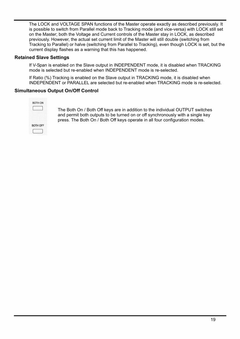
Isolated Ratio (%) Tracking Set the MODE switch to ISOLATED TRACKING.
Ratio Tracking is enabled by pressing the ENABLE key in the Slave VOLTAGE SPAN section (ENABLE lamp on)
The instrument operates as described above for Tracking mode but the Slave voltage can be set to a percentage (0% to 101%) of the Master voltage using the Slave Voltage controls. The ratio is then maintained as the Master voltage is varied.
Pressing ENABLE again returns the Slave to standard Tracking mode (ENABLE lamp off).
Ratio Tracking can only be enabled or disabled with the Slave output off. If the output is on the display will briefly show the message turn oFF when ENABLE is pressed and the change will not be implemented.
Whenever Ratio Tracking mode is enabled the Slave display momentarily shows Pcnt on before reverting to show the actual output voltage now set.
The percentage value can be shown at any time by pressing either the Vmin or Vmax key of the Slave output. With either key held down the Slave display shows the percentage setting in the form 90.0 Pcnt and the Slave Voltage controls can be used to set the ratio percentage required. The ratio percentage can be set prior to Ratio Tracking being enabled (ENABLE lamp off).
The LOCK and VOLTAGE SPAN functions of the Master operate exactly as described previously. However, with Ratio Tracking enabled, the Slave Voltage controls can still be used to adjust the ratio percentage of the Slave voltage even though the Master voltage is locked. The Ratio Tracking mode status at power on is the same as at last power off. See also the Retained Slave Settings paragraph.
Parallel The MODE switch is set to PARALLEL. The instrument operates in true parallel mode with all of the power available from the Master output which can then supply up to 6 amps. The Slave output is disabled and its displays are turned off.
In Parallel mode the value of the current limit is doubled for the same setting of the Current limit control, including the 500mA range which becomes 1000mA max; as a warning, when Parallel mode is first selected, the current display flashes twice before steadily displaying the new limit. Similarly, the current display is flashed twice when the mode is changed from Parallel to Tracking, as a warning that the Master output current limit has now halved.
18
The LOCK and VOLTAGE SPAN functions of the Master operate exactly as described previously. It is possible to switch from Parallel mode back to Tracking mode (and vice-versa) with LOCK still set on the Master; both the Voltage and Current controls of the Master stay in LOCK, as described previously. However, the actual set current limit of the Master will still double (switching from Tracking to Parallel) or halve (switching from Parallel to Tracking), even though LOCK is set, but the current display flashes as a warning that this has happened.
Retained Slave Settings If V-Span is enabled on the Slave output in INDEPENDENT mode, it is disabled when TRACKING mode is selected but re-enabled when INDEPENDENT mode is re-selected.
If Ratio (%) Tracking is enabled on the Slave output in TRACKING mode, it is disabled when INDEPENDENT or PARALLEL are selected but re-enabled when TRACKING mode is re-selected.
Simultaneous Output On/Off Control
The Both On / Both Off keys are in addition to the individual OUTPUT switches and permit both outputs to be turned on or off synchronously with a single key press. The Both On / Both Off keys operate in all four configuration modes.
19
Remote Analogue Control (Single programmable models only)
Remote analogue control of output voltage and current is possible using variable external control voltages applied between the rear panel CV and COM or CC and COM inputs respectively.
The Analogue Out control voltages Vout and Iout of one unit acting as a ‘master’ can be used to control a ‘slave’ unit via the slave’s CV and CC inputs respectively.
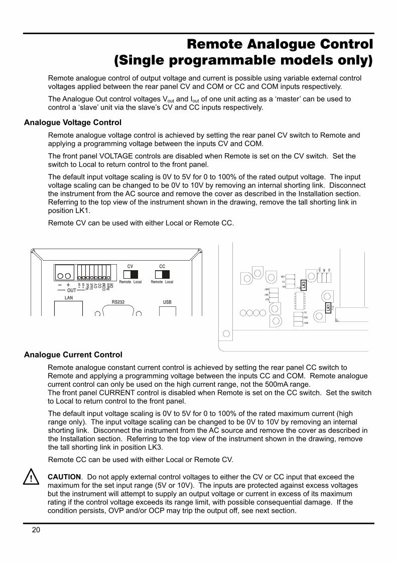
Analogue Voltage Control Remote analogue voltage control is achieved by setting the rear panel CV switch to Remote and applying a programming voltage between the inputs CV and COM.
The front panel VOLTAGE controls are disabled when Remote is set on the CV switch. Set the switch to Local to return control to the front panel.
The default input voltage scaling is 0V to 5V for 0 to 100% of the rated output voltage. The input voltage scaling can be changed to be 0V to 10V by removing an internal shorting link. Disconnect the instrument from the AC source and remove the cover as described in the Installation section. Referring to the top view of the instrument shown in the drawing, remove the tall shorting link in position LK1.
Remote CV can be used with either Local or Remo CC.
A
nalogue Current Control Remote analogue constant current control is achievRemote and applying a programming voltage betwcurrent control can only be used on the high currenThe front panel CURRENT control is disabled whento Local to return control to the front panel.
The default input voltage scaling is 0V to 5V for 0 trange only). The input voltage scaling can be chanshorting link. Disconnect the instrument from the Athe Installation section. Referring to the top view othe tall shorting link in position LK3.
Remote CC can be used with either Local or Remo
CAUTION. Do not apply external control voltages maximum for the set input range (5V or 10V). The but the instrument will attempt to supply an output vrating if the control voltage exceeds its range limit, condition persists, OVP and/or OCP may trip the ou
20
te
ed by setting the rear panel CC switch to een the inputs CC and COM. Remote analogue t range, not the 500mA range. Remote is set on the CC switch. Set the switch
o 100% of the rated maximum current (high ged to be 0V to 10V by removing an internal C source and remove the cover as described in f the instrument shown in the drawing, remove
te CV.
to either the CV or CC input that exceed the inputs are protected against excess voltages oltage or current in excess of its maximum
with possible consequential damage. If the tput off, see next section.
OVP and OCP OVP (over-voltage protection) and OCP (over-current protection) are implemented in firmware and can only be set and used when under remote control via the RS232, USB, LAN (LXI) or GPIB interfaces. Setting resolutions are 10mV and 1mA and typical response times are 500ms. However, in local mode, OVP and OCP are still active but automatically default to 105% of the instrument's range maximum. This usefully provides shut-down protection in the event of prolonged application of a CV or CC control voltage which attempts to set the output beyond 105% of the range maximum.
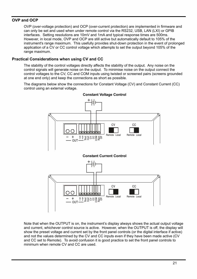
Practical Considerations when using CV and CC The stability of the control voltages directly affects the stability of the output. Any noise on the control signals will generate noise on the output. To minimise noise on the output connect the control voltages to the CV, CC and COM inputs using twisted or screened pairs (screens grounded at one end only) and keep the connections as short as possible.
The diagrams below show the connections for Constant Voltage (CV) and Constant Current (CC) control using an external voltage.
Constant Voltage Control
Constant Current Control
Note that when the OUTPUT is on, the instrument’s display always shows the actual output voltage and current, whichever control source is active. However, when the OUTPUT is off, the display will show the preset voltage and current set by the front panel controls (or the digital interface if active) and not the values determined by the CV and CC inputs even if they have been made active (CV and CC set to Remote). To avoid confusion it is good practice to set the front panel controls to minimum when remote CV and CC are used.
21
Analogue Out Control Voltages Analogue Out control voltages Vout and Iout are generated from the actual internal control voltages, for which the active source can be the front panel controls, the digital interface (RS232, USB, LAN or GPIB) or the remote analogue inputs CV and CC. Vout and Iout are scaled such that 0 to 100% of the rated output voltage and current (high range only) generate 0V to 5V at the rear panel Vout and Iout terminals with respect to COM. COM is connected to the positive output.
Iout always corresponds to the set current, whether the output is on or off, but Vout goes to 0V when the output is off.
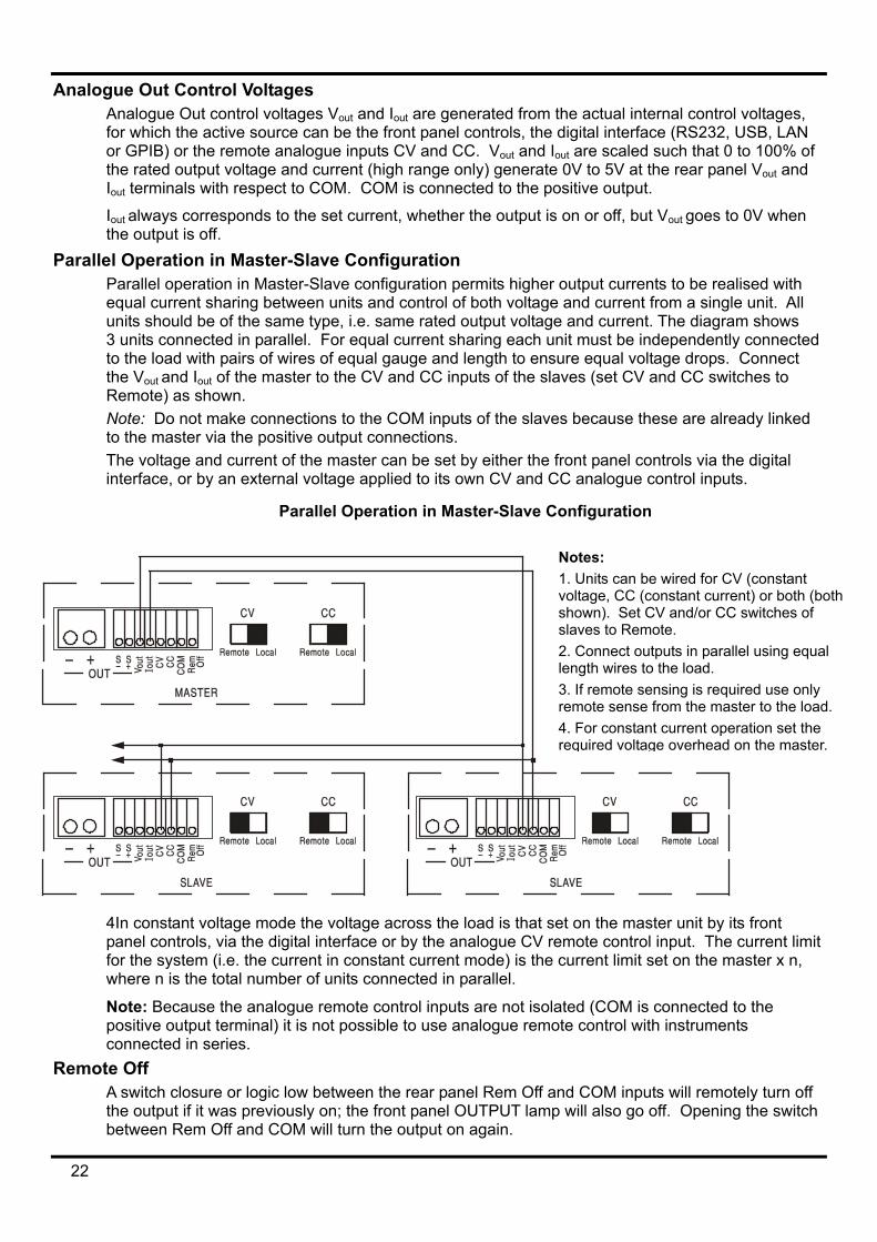
Parallel Operation in Master-Slave Configuration Parallel operation in Master-Slave configuration permits higher output currents to be realised with equal current sharing between units and control of both voltage and current from a single unit. All units should be of the same type, i.e. same rated output voltage and current. The diagram shows 3 units connected in parallel. For equal current sharing each unit must be independently connected to the load with pairs of wires of equal gauge and length to ensure equal voltage drops. Connect the Vout and Iout of the master to the CV and CC inputs of the slaves (set CV and CC switches to Remote) as shown. Note: Do not make connections to the COM inputs of the slaves because these are already linked to the master via the positive output connections. The voltage and current of the master can be set by either the front panel controls via the digital interface, or by an external voltage applied to its own CV and CC analogue control inputs.
Parallel Operation in Master-Slave Configuration
4In constant voltage mode the voltage across the load is that spanel controls, via the digital interface or by the analogue CV rfor the system (i.e. the current in constant current mode) is thewhere n is the total number of units connected in parallel.
Note: Because the analogue remote control inputs are not isopositive output terminal) it is not possible to use analogue remconnected in series.
Remote Off A switch closure or logic low between the rear panel Rem Off athe output if it was previously on; the front panel OUTPUT lambetween Rem Off and COM will turn the output on again.
22
Notes: 1. Units can be wired for CV (constant voltage, CC (constant current) or both (both shown). Set CV and/or CC switches of slaves to Remote. 2. Connect outputs in parallel using equal length wires to the load. 3. If remote sensing is required use only remote sense from the master to the load. 4. For constant current operation set the required voltage overhead on the master.
et on the master unit by its front emote control input. The current limit current limit set on the master x n,
lated (COM is connected to the ote control with instruments
nd COM inputs will remotely turn off p will also go off. Opening the switch
Remote Interface Operation The instrument can be remotely controlled via its RS232, USB, LAN or GPIB (optional) interfaces. Analogue remote control is described in the previous section.
USB remote control operates in a similar way to RS232 but via the USB connector. Software supplied with the instrument sets up the controlling computer to treat the USB connection as a virtual COM port. Application software on the computer can then access the instrument via that COM port.
The LAN interface is designed to meet LXI ( Lan eXtensions for Instrumentation) version 1.2; the instrument is Class C compliant. Remote control using the LAN interface is possible using the TCP/IP Sockets protocol. The instrument also contains a basic Web server which provides information on the unit and allows it to be configured from a web browser. Simple command line control from the browser is also possible.
The instrument is supplied with RS232, USB, and LAN as standard; GPIB is an option. All interfaces are, by default, live at all times (a LXI requirement) but access to individual interfaces may be restricted using the configuration options on the web pages.
Interface Locking All interfaces are live at all times; this removes the need to select the active interface and is also a LXI requirement. To reduce the risk of the instrument being inadvertently under the control of two interfaces at once a simple lock and release mechanism is provided in the instruction set. The lock is automatically released where it is possible to detect disconnection and when the local button is pressed. Access to the interfaces may also be restricted using the web pages.
Any interface may request to have exclusive control of the instrument by sending an “IFLOCK” command. The lock may only be released by sending an “IFUNLOCK” command from the interface instance that currently has the lock and may be queried from any interface by sending an “IFLOCK?” command. The reply to any of these commands will be “-1” if the lock is owned by another interface instance, “0” if the interface is free and “1” if the lock is owned by the requesting interface instance. Sending any command from an interface without control privileges that attempts to change the instrument status will set bit 4 of the Standard Event Status Register and put 200 into the Execution Error Register to indicate that there are not sufficient privileges for the required action.
Note: it is also possible to configure the privileges for a particular interface to either ‘read only’ or ‘no access’ from the Web page interface.
Address Selection The instrument address capability is strictly required only by the GPIB interface. However, use can be made of the ADDRESS? command over any of the interfaces to easily identify which instrument is being controlled by a particular COM port (for RS232 or USB) or TCP socket (for LAN). Note that the LAN interface also has a separate ‘Identify’ function, accessible from the instrument’s web pages, that flashes the instrument’s display until the function is cancelled.
The address is set from the instrument’s front panel as follows. Start with the instrument off and, with the Lock, Meter Average and Current Range keys all held down (SLAVE output only on dual), switch the instrument on. The display will show Addr in the Volts display and nn in the mA display where nn is the present setting (default Addr 11 ). The address can be decremented and incremented by the Meter Average and Current Range keys respectively in the range 1 to 31 inclusive (not 0), with 'wrap-round'. The address is confirmed and the process exited by holding down the Lock key; the display will show SEt and the new address for approximately 2 seconds, returning to the normal Volts and mA display when the new address has been accepted.
The address can also be set from the instrument’s web pages.
23
Remote/Local Operation At power-on the instrument will be in the local state with the REMOTE indicator off. In this state all front panel operations are possible. When the instrument is addressed to listen and a command is received the remote state will be entered and REMOTE will be turned on. In this state the front panel is locked out and remote commands only will be processed. The V/I settings, Meter Average setting, Current Range and output state(s) are unchanged but LOCK and V-Span are cancelled if they were on. The Vmin and Vmax values are retained. The MODE (QMD-P models only) and Sense settings remain as set by the front panel switches. The instrument may be returned to the local state by pressing the LOCAL key; however, the effect of this action will only remain until the instrument is addressed again or receives another character from the interface, when the remote state will once again be entered. Returning to Local by this action, or by the use of the LOCAL command, will keep the V/I settings at their last remotely set values, with Lock Settings on, and will leave the output(s) in their present state.
RS232 Interface RS232 Interface Connector
The 9-way D-type serial interface connector is located on the instrument rear panel. The pin connections are as shown below:
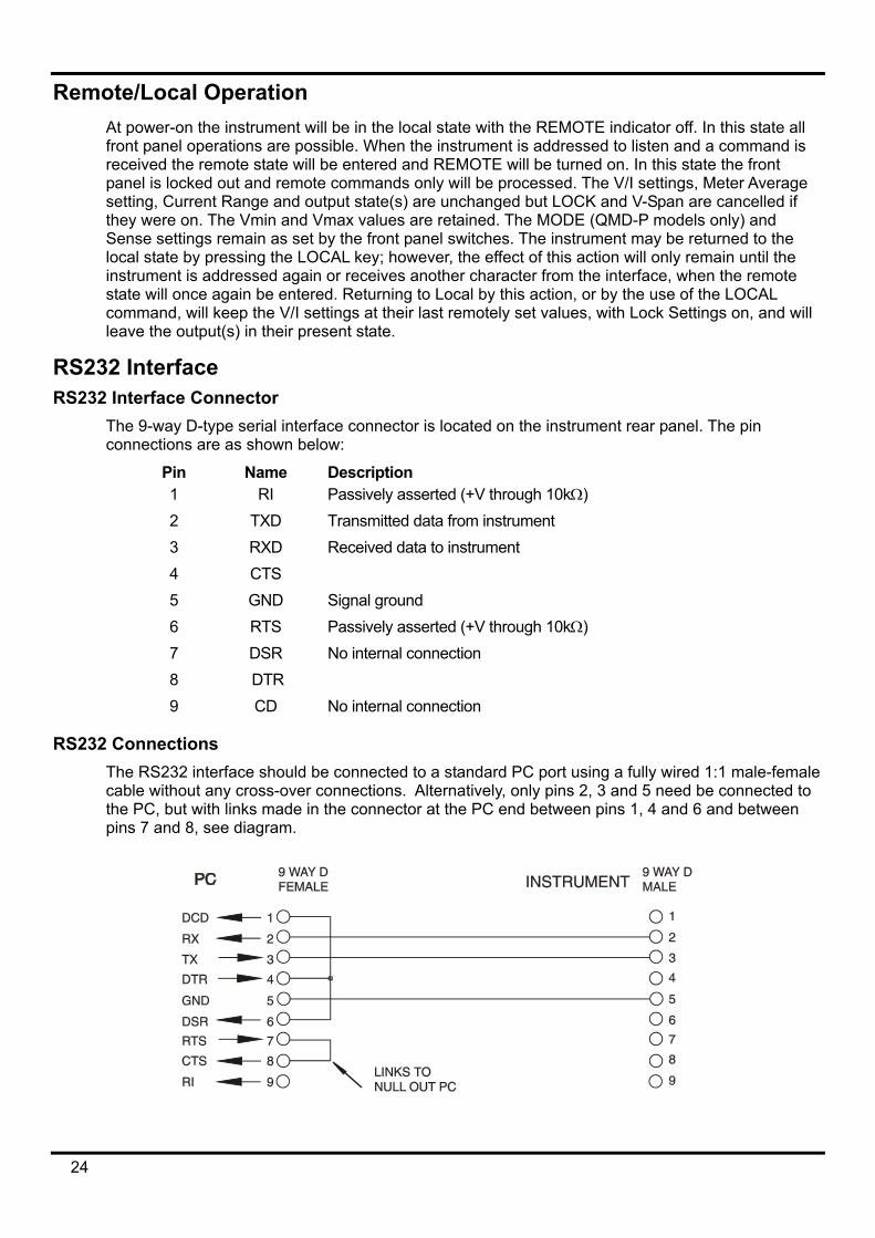
Pin Name Description 1 RI Passively asserted (+V through 10kΩ) 2 TXD Transmitted data from instrument 3 RXD Received data to instrument 4 CTS 5 GND Signal ground 6 RTS Passively asserted (+V through 10kΩ) 7 DSR No internal connection 8 DTR 9 CD No internal connection
RS232 Connections The RS232 interface should be connected to a standard PC port using a fully wired 1:1 male-female cable without any cross-over connections. Alternatively, only pins 2, 3 and 5 need be connected to the PC, but with links made in the connector at the PC end between pins 1, 4 and 6 and between pins 7 and 8, see diagram.
24
Baud Rate for this instrument is fixed at 9600; the other parameters are fixed as follows:
Start Bits: 1 Parity: None
Data Bits: 8 Stop Bits: 1
RS232 Character Set Because of the need for XON/XOFF handshake it is possible to send ASCII coded data only; binary blocks are not allowed. Bit 7 of ASCII codes is ignored, i.e. assumed to be low. No distinction is made between upper and lower case characters in command mnemonics and they may be freely mixed. The ASCII codes below 20H (space) are not used. In this manual 20H, etc. means 20 in hexadecimal. The unit will send XOFF when there are 50 free bytes remaining and XON when this increases to 100 bytes.
USB Interface The USB interface is a virtual COM port which can be controlled by a PC as if it was a RS232 device. The instrument is supplied with a CD containing an .inf file for the standard Microsoft drivers available in Windows 2000, XP, Vista and Windows 7; the installation wizard will install the driver (32-bit or 64-bit) appropriate to the PC’s operating system. Any updates are available via the TTi website, www.tti-test.com.
Installation of the interface driver is achieved by connecting the instrument to a PC via a standard USB cable. The Windows’ plug and play functions should automatically recognise the addition of new hardware attached to the USB interface and, if this is the first time the connection has been made, prompt for the location of a suitable driver. Provided that the standard Windows prompts are followed correctly Windows will install the appropriate driver and establish a virtual COM port within the PC. The number of the new COM port will depend upon the number of co-existing COM ports within the PC. The virtual COM port can be driven by Windows applications in exactly the same way as a standard COM port, except that the Baud rate setting of the virtual COM port is ignored.
The driver will remain installed on the PC so that the establishment of a virtual COM port is done automatically each time the instrument is connected to the PC via USB in the future.
Further virtual COM ports are created for each additional instrument connected to the PC via USB. Each instrument is assigned a separate virtual COM port when it is first connected and the same COM port will be assigned each time that instrument is subsequently connected; the PC software makes use of the unique code embedded in each instrument to link it to the same virtual COM port irrespective of which physical USB port it is connected to.
Use can also be made of the ADDRESS? command to easily identify which instrument is being controlled by a particular COM port. Although the addressing capability is ignored in USB operation the address can still be set and used as an identifier; set each USB-connected instrument to a different address and send the ADDRESS? command from each virtual COM port to confirm which instrument is connected to that port.
LAN Interface The LAN interface is designed to comply with the LXI standard version 1.2 and contains the interfaces and protocols described below. Since it is possible to misconfigure the LAN interface, making it impossible to communicate with the instrument over LAN, a LAN Configuration Initialise (LCI) mechanism is provided via a recessed switch on the rear panel to reset the unit to the factory default. The default setting is for the instrument to attempt to obtain settings via DHCP if available or, if DHCP times out (30 seconds), via Auto-IP. In the very unlikely event that an Auto-IP address cannot be found a static IP address of 192.168.0.100 is assigned. Resetting the LAN removes any password protection.
For more information on LXI standards refer to www.lxistandard.org/home .
25
LAN Connection To use the LAN interface, the IP address of the unit must be known. There is a LXI Discovery Tool on the supplied CD-ROM which can be used to display the IP addresses (and other associated information) of all connected devices that comply with the VXI-11 discovery protocol. This tool is a Windows PC application that should be installed and run on the controlling PC with the unit either connected directly to the PC network connector or via a router. Connecting via a router is recommended as this is significantly quicker to assign an IP address; connecting directly to the PC will begin to assign an IP address only after a 30 second DHCP timeout. Double clicking on any entry in the list of devices discovered will open the PC's web browser and display the Home page of that device.
There are also tools for LAN discovery included as part of the National Instruments Measurement and Automation Explorer package and the Agilent Vee application.
The unit will, when first powered up, attempt to obtain settings via DHCP if available or, if DHCP times out (30 seconds), via Auto-IP. In the very unlikely event that an Auto-IP address cannot be found a static IP address of 192.168.0.100 is assigned. If a connection is still not made the instrument will flash LAn Err in the display, see LAN Error section for details.
Web Server; Configuration Password Protection The unit contains a basic web server. This provides information on the instrument and allows it to be configured. The Configure page can be password protected to deter unauthorised changes to the remote operation configuration; the default configuration is ‘no password’.
The Configure page itself explains how to set the password. The password can be up to 15 characters long; note that the User Name should be left blank. The password will, however, be reset to the default (no password) if the rear panel LAN RESET switch is used to reset all the LAN parameters to their factory default.
The web pages also have an ‘Identify’ function which allows the user to send an identifying command to the instrument which causes its display to flash until the command is cancelled.
ICMP Ping Server The unit contains an ICMP server allowing the instrument to be ‘pinged’ via either its host name or IP address.
VXI-11 Discovery Protocol The instrument has very limited support of VXI-11 which is sufficient for the discovery protocol and no more.
The instrument implements a Sun RPC Port-mapper on TCP port 111 and UDP port 111 as defined in RPC1183. The calls supported are: NULL, GET PORT and DUMP.
On TCP port 1024 a very simple VXI-11 protocol is implemented sufficient only for instrument discovery. This implements the following calls: CREATE LINK, DEVICE_WRITE, DEVICE_READ and DESTROY_LINK.
Once a link has been created anything written to the device is ignored and any read from the device returns the identification string as would be expected from a “*IDN?” of the form
‘Manufacturer,Model,Serial No.,X.xx – Y.yy’
for example
THURLBY THANDAR,PL601-P,279730,1.00 – 1.00 where ‘X.xx’ is the revision of the main firmware and ‘Y.yy’ is the revision of the interface firmware. Interface firmware is user field updateable via the USB port.
26
VISA Resource Name Because of the limited support for VXI-11(Discovery Protocol only), the instrument must be referred to by its raw socket information when used in software packages which communicate via a VISA resource name. For example, an instrument at IP address 192.168.1.100 would normally have a VISA resource name of "TCPIP0::192.168.1.100::inst0::INSTR" but for this instrument the name must be modified to read "TCPIP0::192.168.1.100::9221::SOCKET" where 9221 is the TCP port used by this instrument for control and monitoring, see below.
XML Identification Document URL As required by the LXI Standard, the instrument provides an XML identification document that can be queried via a GET at “http://<hostname>:80/lxi/identification” that conforms to the LXI XSD Schema (available at http://www.lxistandard.org/InstrumentIdentification/1.0) and the W3C XML Schema Standards ( http://www.w3.org/XML/Schema ). This document describes the instrument.
TCP Sockets The instrument uses 2 sockets on TCP port 9221 for instrument control and monitoring. Text commands are sent to this port as defined in ‘Remote Commands’ and any replies are returned via the same port. Any string must be one or more complete commands. Commands may be separated with either semicolons “;” or line feeds. No terminator is required since the TCP frame contains complete commands though commands may be sent with a terminator if desired (it will be ignored). Each command over TCP behaves as if it is terminated with a command terminator (ASCII character 0AH, line feed).
LAN Error If a LAN connection is made but an error is detected (e.g. the IP address is the same as another device on the network) then the instrument’s display will flash alternately between the normal voltage and current values and LAn Err, until the error is corrected. If a LAN error occurs; check and correct the configuration of the instrument; a LAN Configuration Initialise (LCI) mechanism is provided via a recessed switch on the rear panel ( marked LAN RESET) to reset the unit to the factory default. The default setting is for the instrument to attempt to obtain settings via DHCP if available or, if DHCP times out (30 seconds), via Auto-IP. In the very unlikely event that an Auto-IP address cannot be found a static IP address of 192.168.0.100 is assigned. The display will also flash alternately between the normal values and LAn Err if no physical LAN connection is found at power on, but will stop flashing after 10 seconds. To disable this message at every power on send the command 'NOLANOK 1' over any interface. To re-enable the message at power on send the command 'NOLANOK 0 ' or use the recessed rear panel LAN RESET switch to reset all LAN parameters to their factory default settings, see the introduction to the LAN section.
GPIB Interface The GPIB interface 24-way connector is located on the instrument rear panel. The pin connections are as specified in IEEE Std. 488.1-1987 and the instrument complies with IEEE Std. 488.1-1987 and IEEE Std. 488.2-1987.
GPIB Subsets This instrument contains the following IEEE 488.1 subsets:
Source Handshake SH1 Acceptor Handshake AH1 Talker T6 Listener L4 Service Request SR1 Remote Local RL2 Parallel Poll PP1 Device Clear DC1 Device Trigger DT0 Controller C0 Electrical Interface E2
27
GPIB IEEE Std. 488.2 Error Handling – Query Error Register The IEEE 488.2 UNTERMINATED error (addressed to talk with nothing to say) is handled as follows. If the instrument is addressed to talk and the response formatter is inactive and the input queue is empty then the UNTERMINATED error is generated. This will cause the Query Error bit to be set in the Standard Event Status Register, a value of 3 to be placed in the Query Error Register and the parser to be reset. See the Status Reporting section for further information.
The IEEE 488.2 INTERRUPTED error is handled as follows. If the response formatter is waiting to send a response message and a <PROGRAM MESSAGE TERMINATOR> has been read by the parser or the input queue contains more than one END message then the instrument has been INTERRUPTED and an error is generated. This will cause the Query Error bit to be set in the Standard Event Status Register, a value of 1 to be placed in the Query Error Register and the response formatter to be reset thus clearing the output queue. The parser will then start parsing the next <PROGRAM MESSAGE UNIT> from the input queue. See the Status Reporting section for further information.
The IEEE 488.2 DEADLOCK error is handled as follows. If the response formatter is waiting to send a response message and the input queue becomes full then the instrument enters the DEADLOCK state and an error is generated. This will cause the Query Error bit to be set in the Standard Event Status Register, a value of 2 to be placed in the Query Error Register and the response formatter to be reset thus clearing the output queue. The parser will then start parsing the next <PROGRAM MESSAGE UNIT> from the input queue. See the Status Reporting section for further information.
GPIB Parallel Poll Complete parallel poll capabilities are offered on this instrument. The Parallel Poll Enable Register is set to specify which bits in the Status Byte Register are to be used to form the ist local message The Parallel Poll Enable Register is set by the *PRE <nrf> command and read by the *PRE? command. The value in the Parallel Poll Enable Register is ANDed with the Status Byte Register; if the result is zero then the value of ist is 0 otherwise the value of ist is 1.
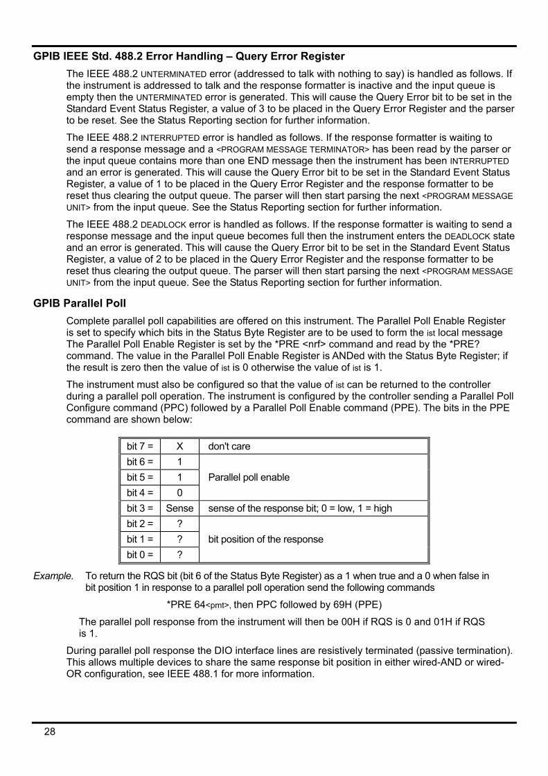
The instrument must also be configured so that the value of ist can be returned to the controller during a parallel poll operation. The instrument is configured by the controller sending a Parallel Poll Configure command (PPC) followed by a Parallel Poll Enable command (PPE). The bits in the PPE command are shown below:
bit 7 = X don't care bit 6 = 1 bit 5 = 1 Parallel poll enable bit 4 = 0 bit 3 = Sense sense of the response bit; 0 = low, 1 = high bit 2 = ? bit 1 = ? bit position of the response bit 0 = ?
Example. To return the RQS bit (bit 6 of the Status Byte Register) as a 1 when true and a 0 when false in bit position 1 in response to a parallel poll operation send the following commands
*PRE 64<pmt>, then PPC followed by 69H (PPE)
The parallel poll response from the instrument will then be 00H if RQS is 0 and 01H if RQS is 1.
During parallel poll response the DIO interface lines are resistively terminated (passive termination). This allows multiple devices to share the same response bit position in either wired-AND or wired-OR configuration, see IEEE 488.1 for more information.
28
Status Reporting A separate error and status model is maintained for each interface instance; an interface instance is defined as a potential connection. USB, RS232 and GPIB are inherently single connections so represent one interface instance each. LAN, however, allows for multiple simultaneous connections and therefore represents multiple interface instances. Two interface instances are allocated to the two TCP socket interfaces and one more is allocated to the Web page interface. Having a separate model for each interface instance ensures that data does not get lost as many commands e.g. ‘*ESR?’ clear the contents on read.
Error status is maintained using a set of registers; these are described in the following paragraphs and shown on the Status Model at the end of this section.
Standard Event Status and Standard Event Status Enable Registers These two registers are implemented as required by the IEEE Std. 488.2. Any bits set in the Standard Event Status Register which correspond to bits set in the Standard Event Status Enable Register will cause the ESB bit to be set in the Status Byte Register.
The Standard Event Status Register is read and cleared by the *ESR? command. The Standard Event Status Enable register is set by the *ESE <nrf> command and read by the *ESE? command.
It is a bit field where each bit has the following significance.
Bit 7: Power On. Set when power is first applied to the instrument.
Bit 6: User Request (Not used).
Bit 5: Command Error. Set when a syntax type error is detected in a command from the bus. The parser is reset and parsing continues at the next byte in the input stream
Bit 4: Execution Error. Set when an error is encountered while attempting to execute a completely parsed command. The appropriate error number will be reported in the Execution Error Register, see Error Messages section
Bit 3: Verify Timeout Error. Set when a parameter is set with 'verify' specified and the value is not reached within 5 seconds, e.g. output voltage is slowed by a large capacitor on the output.
Bit 2: Query Error. Set when a query occurs. The appropriate error number will be reported in the Query Error Register, see Query Error Register section.
Bit 1: Not used.
Bit 0: Operation Complete: Set in response to the ‘*OPC’ command.
Execution Error Register This register contains a number representing the last error encountered over the current interface. The Execution Error Register is read and cleared using the ‘EER?’ command. On power up this register is set to 0 for all interface instances.
Error messages have the following meaning:
0: No error encountered
1-9: Internal hardware error detected.
100: Range error. The numeric value sent is not allowed. This includes numbers that are too big or too small for the parameter being set and non-integers being sent where only integers are allowed.
101: A recall of set up data has been requested but the store specified contains corrupted data. This indicates either a hardware fault or a temporary data corruption, which can be corrected by writing data to the store again.
102: A recall of set up data has been requested but the store specified does not contain any data.
29
103: Attempt to read or write a command on the second output when it is not available.
Typically this will occur if attempting to program the second output on single channel instruments or on a two-channel instrument which is set to parallel mode.
104: Command not valid with output on. This is typically caused by using the 'IRANGE <n>' command without first turning the output off.
200: Read Only: An attempt has been made to change the settings of the instrument from an interface without write privileges, see the Interface Locking section.
Limit Event Status and Limit Event Status Enable Registers For single output power supplies there is one Limit Event Status Register; for dual power supplies (except if operating in parallel mode) there are two. These are read and cleared using ‘LSR1?’ and ‘LSR2?’ respectively. On power-up these registers are set to 0 then immediately set to show new limit status.
Any bits set in a Limit Event Status Register which correspond to bits set in the accompanying Limit Event Status Enable Register will cause the LIM1 or LIM2 bit to be set in the Status Byte Register.
Bit 7: Reserved for future use Bit 6: Set when a trip has occurred that can only be reset from the front panel or by removing
and reapplying the AC power. Bit 5: Reserved for future use Bit 4: Reserved for future use Bit 3: Set when an output over current trip has occurred Bit 2: Set when an output over voltage trip has occurred. Bit 1: Set when output enters current limit (CC mode) Bit 0: Set when output enters voltage limit (CV mode)
Status Byte Register and Service Request Enable Register These two registers are implemented as required by the IEEE Std. 488.2. Any bits set in the Status Byte Register which correspond to bits set in the Service Request Enable Register will cause the RQS/MSS bit to be set in the Status Byte Register, thus generating a Service Request on the bus. The Status Byte Register is read either by the *STB? command, which will return MSS in bit 6, or by a Serial Poll which will return RQS in bit 6. The Service Request Enable register is set by the *SRE <nrf> command and read by the *SRE? command. Bit 7 - Not used. Bit 6 - RQS/MSS. This bit, as defined by IEEE Std. 488.2, contains both the Requesting Service
message and the Master Status Summary message. RQS is returned in response to a Serial Poll and MSS is returned in response to the *STB? command.
Bit 5 - ESB. The Event Status Bit. This bit is set if any bits set in the Standard Event Status Register correspond to bits set in the Standard Event Status Enable Register.
Bit 4 - MAV. The Message Available Bit. This will be set when the instrument has a response message formatted and ready to send to the controller. The bit will be cleared after the Response Message Terminator has been sent.
Bit 3 - Not used. Bit 2 - Not used. Bit 1 - LIM2. This will be set if any bits in Limit Event Status Register 2 are set and
corresponding bits are set in Limit Event Status Enable Register 2. Bit 0 - LIM1. This will be set if any bits in Limit Event Status Register 1 are set and
corresponding bits are set in Limit Event Status Enable Register 1.
30
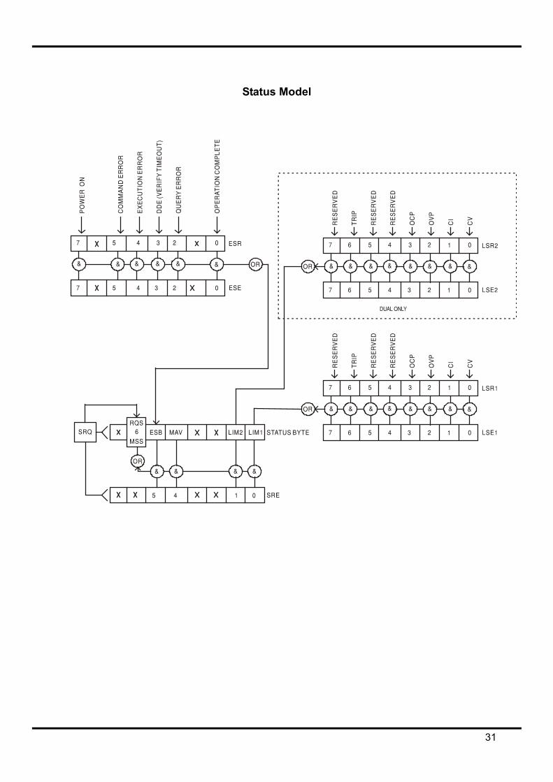
Status Model
31
Power-on and Remote Operation Default Settings The following instrument status values are set at power on:
Status Byte Register = 0
Service Request Enable Register † = 0
Standard Event Status Register = 128 (pon bit set)
Standard Event Status Enable Register † = 0
Execution Error Register = 0
Query Error Register = 0
Parallel Poll Enable Register † = 0
† Registers marked thus are specific to the GPIB section of the instrument and are of limited use via other interfaces.
The instrument will be in local state with the front panel controls active (providing rear panel switches CV and CC are set to Local.
The instrument parameters at power-on are the same as at last switch off with the exception of the output status. By default this is always off at power on but the user may change this from the front panel to the same at power on as at switch off, see Switching On and Power-on Conditions paragraph in the Manual Operation section.
The *RST (reset) interface command resets the instrument to the Remote Operation Default settings.
Remote Operation Default settings are: Vout=0.1V, Iout=100mA, DeltaV=10mV, DeltaI=1mA, Vmin=3V, Vmax=5V, Tracking Ratio = 100%, Lock cancelled, V-Span cancelled, 500mA Range cancelled, Meter Average cancelled, OVP & OCP at 5% above instrument range maximums.
Remote interface settings, stored set-ups, Vmin/Vmax values and Output state at power-on setting are unchanged by *RST.
Mode and Sense settings are as determined by the front panel switches.
32
Remote Commands RS232/USB Remote Command Format
RS232 input to the instrument is buffered in a 256 byte input queue which is filled, under interrupt, in a manner transparent to all other instrument operations. The instrument will send XOFF when approximately 200 characters are in the queue. XON will be sent when approximately 100 free spaces become available in the queue after XOFF was sent. This queue contains raw (un-parsed) data which is taken, by the parser, as required. Commands (and queries) are executed in order and the parser will not start a new command until any previous command or query is complete. RS232 responses to commands or queries are sent immediately; there is no output queue.
USB input conforms with USB 2.0 Full Speed.
Commands must be sent as specified in the commands list and must be terminated with the command terminator code 0AH (Line Feed, LF). Commands may be sent in groups with individual commands separated from each other by the code 3BH (;). The group must be terminated with command terminator 0AH (Line Feed, LF).
Responses from the instrument to the controller are sent as specified in the commands list. Each response is terminated by a <RESPONSE MESSAGE TERMINATOR> which is 0DH (Carriage Return, CR) followed by 0AH (Line Feed, LF).
<WHITE SPACE> is defined as character codes 00H to 20H inclusive.
<WHITE SPACE> is ignored except in command identifiers. e.g. '*C LS' is not equivalent to '*CLS'.
The high bit of all characters is ignored.
The commands are case insensitive.
GPIB Remote Command Formats GPIB input to the instrument is buffered in a 256 byte input queue which is filled, under interrupt, in a manner transparent to all other instrument operations. The queue contains raw (un-parsed) data which is taken, by the parser, as required. Commands (and queries) are executed in order and the parser will not start a new command until any previous command or query is complete. There is no output queue which means that the response formatter will wait, indefinitely if necessary, until the instrument is addressed to talk and the complete response message has been sent, before the parser is allowed to start the next command in the input queue.
Commands are sent as <PROGRAM MESSAGES> by the controller, each message consisting of zero or more <PROGRAM MESSAGE UNIT> elements separated by <PROGRAM MESSAGE UNIT SEPARATOR> elements.
A <PROGRAM MESSAGE UNIT> is any of the commands in the remote commands list.
A <PROGRAM MESSAGE UNIT SEPARATOR> is the semi-colon character ';' (3BH).
<PROGRAM MESSAGES> are separated by <PROGRAM MESSAGE TERMINATOR> elements which may be any of the following:
NL The new line character (0AH)
NL^END The new line character with the END message
^END The END message with the last character of the message
Responses from the instrument to the controller are sent as <RESPONSE MESSAGES>. A <RESPONSE MESSAGE> consists of one <RESPONSE MESSAGE UNIT> followed by a <RESPONSE MESSAGE TERMINATOR>.
A <RESPONSE MESSAGE TERMINATOR> is the new line character with the END message NL^END.
33
Each query produces a specific <RESPONSE MESSAGE> which is listed along with the command in the remote commands list.
<WHITE SPACE> is ignored except in command identifiers. e.g. '*C LS' is not equivalent to '*CLS'. <WHITE SPACE> is defined as character codes 00H to 20H inclusive with the exception of the NL character (0AH).
The high bit of all characters is ignored.
The commands are case insensitive.
Command List This section lists all commands and queries implemented in this instrument.
Note that there are no dependent parameters, coupled parameters, overlapping commands, expression program data elements or compound command program headers; each command is completely executed before the next command is started. All commands are sequential and the operation complete message is generated immediately after execution in all cases.
The following nomenclature is used:
<rmt> <RESPONSE MESSAGE TERMINATOR>
<nrf> A number in any format. e.g. 12, 12·00, 1·2 e1 and 120 e-1 are all accepted as the number 12. Any number, when received, is converted to the required precision consistent with the use then rounded to obtain the value of the command.
<nr1> A number with no fractional part, i.e. an integer.
<nr2> A number in fixed point format e.g. 11·52, 0·78 etc.
<n> The number of the output (1 or 2) or associated status register to which the command relates. On dual output supplies, ‘1’ is the Master (right-hand output) and ‘2’ is the Slave (left-hand output). On single output supplies <n> is always 1.
The commands which begin with a * are implemented as specified by IEEE Std 488.2 as Common commands. All will function when used on the other interfaces but some may be of little use.
Instrument Specific Commands For commands specified as 'WITH VERIFY' the operation is completed when the parameter being adjusted reaches the required value to within ±5% or ±10 counts, whichever is the greater. If the value fails to settle within these limits within 5 seconds then the Verify Timeout bit (bit 3) is set in the Standard Event Status Register and the operation is completed at the end of the timeout period.
The Operation Complete bit (bit 0) in the Standard Event Status Register is only ever set by the *OPC command. The *OPC (or the *OPC?) command can be used for device synchronisation due to the sequential nature of remote operations.
V<n> <nrf> Set output <n> to <nrf> Volts
V<n>V <nrf> Set output <n> to <nrf> Volts with verify
OVP<n> <nrf> Set output <n> over voltage protection trip point to <nrf> Volts
I<n> <nrf> Set output <n> current limit to <nrf> Amps
OCP<n> <nrf> Set output <n> over current protection trip point to <nrf> Amps
V<n>? Returns the set voltage of output <n> The response is V <n> <nr2><rmt> where <nr2> is in Volts
I<n>? Returns the set current limit of output <n> The response is I <n> <nr2><rmt> where <nr2> is in Amps
34
OVP<n>? Returns the voltage trip setting for output <n> The response is VP<n> <nr2><rmt> where <nr2> is in Volts
OCP<n>? Returns the current trip setting for output <n> The response is CP<n> <nr2><rmt> where <nr2> is in Amps
V<n>O? Returns the output readback voltage for output <n> The response is <nr2>V<rmt> where <nr2> is in Volts
I<n>O? Returns the output readback current for output <n> The response is <nr2>A<rmt> where <nr2> is in Amps
IRANGE<n> <nrf> Sets the current range of output <n> to <nrf>, where <nrf> is 1 for Low (500mA) range, 2 for High range. Output must be switched off before changing range.
IRANGE<n>? Report the current range for output <n>. The response is <nr1><rmt>, where <nr1> is 1 for Low (500mA) range, 2 for High range.
DELTAV<n> <nrf> Set the output <n> voltage step size to <nrf> Volts
DELTAI<n> <nrf> Set the output <n> current step size to <nrf> Amps
DELTAV<n>? Returns the output <n> voltage step size The response is DELTAV<n> <nr2><rmt> where <nr2> is in Volts.
DELTAI<n>? Returns the output <n> current step size The response is DELTAI<n> <nr2><rmt> where <nr2> is in Amps.
INCV<n> Increment the output <n> voltage by the step size set for output <n>
INCV<n>V Increment the output <n> voltage by the step size set for output <n> and verify.
DECV<n> Decrement the output <n> voltage by the step size set for output <n>
DECV<n>V Decrement the output <n> voltage by the step size set for output <n> and verify
INCI<n> Increment the output <n> current limit by the step size set for output <n>
DECI<n> decrement the output <n> current limit by the step size set for output <n>
OP<n> <nrf> set output <n> on/off where <nrf> has the following meaning: 0=OFF, 1=ON
OPALL <nrf> Simultaneously sets all outputs on/off where <nrf> has the following meaning: 0=ALL OFF, 1=ALL ON. If OPALL sets all outputs ON then any that were already on will remain ON If OPALL sets all outputs OFF then any that were already off will remain OFF
OP<n>? Returns output <n> on/off status. The response is <nr1><rmt> where 1 = ON, 0 = OFF.
TRIPRST Attempt to clear all trip conditions.
LOCAL Go to local. This does not release any active interface lock so that the lock remains with the selected interface when the next remote command is received.
IFLOCK Request interface lock. This command requests exclusive access control of the instrument. The response is 1 if successful or –1 if the lock is unavailable either because it is already in use or the user has disabled this interface from taking control using the web interface
IFLOCK? Query the status of the interface lock. The return value is 1 if the lock is owned by the requesting interfaced instance; 0 if there is no active lock or –1 if the lock is unavailable either because it is already in use, or the user has disabled this interface from taking control using the web interface.
35
IFUNLOCK Release the lock if possible. This command returns the value 0 if successful. If this command is unsuccessful –1 is returned, 200 is placed in the Execution Register and bit 4 of the Event Status Register is set indicating that there is no authority to release the lock.
LSR<n>? Query and clear Limit Event Status Register <n>. The response is <nr1><rmt>. See Status Reporting section for details.
LSE<n> <nrf> Set the value of LSE<n>, Limit Event Status Enable Register <n>, to <nrf>
LSE<n>? Return the value of LSE<n>, Limit Event Status Enable Register <n> - response is <nr1><rmt>
SAV<n> <nrf> Save the current set-up of output <n> to the set-up store specified by <nrf> where <nrf> can be 0-9.
RCL<n> <nrf> Recall a set up for output <n> from the set-up store specified by <nrf> where <nrf> can be 0-9.
RATIO <nrf> Set the ratio of output 2 (slave) to output 1 (master) in tracking mode to <nrf>, where <nrf> is the ratio in percent (0 to 100).
RATIO? Query the ratio of output 2 (slave) to output 1 (master) in tracking mode. The response is <nrf>, where <nrf> is the ratio in percent (0 to 100).
System and Status Commands
*CLS Clear Status. Clears the Status structure. This indirectly clears the Status Byte Register.
EER? Query and clear Execution Error Register. The response format is nr1<rmt>.
*ESE <nrf> Set the Standard Event Status Enable Register to the value of <nrf>
*ESE? Returns the value in the Standard Event Status Enable Register in <nr1> numeric format. The syntax of the response is <nr1><rmt>
*ESR? Returns the value in the Standard Event Status Register in <nr1> numeric format. The register is then cleared. The response is <nr1><rmt>. See Status Reporting section for details.
*IST? Returns ist local message as defined by IEEE Std. 488.2. The syntax of the response is 0<rmt>, if the local message is false, or 1<rmt>, if the local message is true.
*OPC Sets the Operation Complete bit (bit 0) in the Standard Event Status Register. This will happen immediately the command is executed because of the sequential nature of all operations.
*OPC? Query Operation Complete status. The response is always 1<rmt> and will be available immediately the command is executed because all commands are sequential.
*PRE <nrf> Set the Parallel Poll Enable Register to the value <nrf>. *PRE? Returns the value in the Parallel Poll Enable Register in <nr1> numeric format.
The syntax of the response is <nr1><rmt>
QER? Query and clear Query Error Register. The response format is nr1<rmt> *RST Resets the instrument to the remote control default settings with the exception of
all remote interface settings, stored set-ups, Vmin/Vmax values and Output state at power-on setting. (see Remote Operation Defaults paragraph in the Remote Interface Operation section)
36
*SRE <nrf> Set the Service Request Enable Register to <nrf>. *SRE? Returns the value of the Service Request Enable Register in <nr1> numeric
format. The syntax of the response is<nr1><rmt> *STB? Returns the value of the Status Byte Register in <nr1> numeric format. The
syntax of the response is<nr1><rmt> *WAI Wait for Operation Complete true. As all commands are completely executed
before the next is started this command takes no additional action.
Miscellaneous Commands
*IDN? Returns the instrument identification. The exact response is determined by the instrument configuration and is of the form <NAME>,<model>,<Serial No.>, <version><rmt> where <NAME> is the manufacturer's name, <model> defines the type of instrument, Serial No. is the unique serial number and <version> is the revision level of the software installed. The format of <version> is X.xx – Y.yy where X.xx is the revision of the main instrument firmware and Y.yy is the revision of the Interface board firmware. The Interface firmware is field updateable by the user via the USB port.
ADDRESS? Returns the bus address of the instrument; This is the address used by GPIB, if fitted, or may be used as a general identifier over the other interfaces.
CONFIG? Reports the operating mode set by the front panel MODE switch. The syntax of the response is <nr1><rmt>, where <nr1> is 1 for single channel units and dual units operating in parallel mode, 2 for dual units with both channels operating independently and 0 for dual units in tracking mode.
DAMPING<n> <nrf> Set the current meter measurement averaging ( IAVG ) of output <n> where <nrf> has the following meaning: 0 = OFF, 1 = ON.
NOLANOK <nrf> Disables the LAn Err message for no LAN connection found at power on if <nrf> is 1 and enables the message if <nrf> is 0.
*TST? The PSU has no self test capability and the response is always 0 <rmt>
*TRG The PSU has no trigger capability. The command is accepted but performs no action.
Error Messages Each error message has a number; only this number is reported via the remote control interfaces. Error message numbers are not displayed but are placed in the Execution Error Register where they can be read via the remote interfaces, see Status Reporting section.
37
Maintenance The Manufacturers or their agents overseas will provide a repair service for any unit developing a fault. Where owners wish to undertake their own maintenance work, this should only be done by skilled personnel in conjunction with the service manual which may be purchased directly from the Manufacturers or their agents overseas.
Cleaning
If the instrument requires cleaning use a cloth that is only lightly dampened with water or a mild detergent.
WARNING! TO AVOID ELECTRIC SHOCK, OR DAMAGE TO THE INSTRUMENT, NEVER ALLOW WATER TO GET INSIDE THE CASE. TO AVOID DAMAGE TO THE CASE NEVER CLEAN WITH SOLVENTS.
Web link For the latest version of this instruction manual, IVI driver and any applicable firmware updates go to http://www.tti-test.com/go/psx
38

Thurlby Thandar Instruments Ltd.Glebe Road • Huntingdon • Cambridgeshire • PE29 7DR • England (United Kingdom)
Telephone: +44 (0)1480 412451 • Fax: +44 (0)1480 450409 International web site: www.tt i-test.com • UK web site: www.tt i.co.uk
Email: info@tt i-test.com
Aim Instruments and Thurlby Thandar Instruments Book Part No. 48511-1140 Issue 10