Embed Size (px)
Citation preview
New Hampshire Public Utilities Commission Model Propane Operating & Maintenance and Emergency
Plans
The New Hampshire Public Utilities Commission, courtesy of the Maine Public Utilities Commission, is providing these Model LPG Operation & Maintenance and Emergency Plans to assist jurisdictional propane facilities operators in complying with state statutes and regulations within the Commission’s jurisdiction. The Commission’s regulations specifically adopt 49 Code of Federal regulations, Parts 192.605 and 192.615, however, this model plan is only intended to assist in compliance with state, not federal laws.
1
[Company Name]
Liquefied Petroleum Gas (Propane)
Operations & Maintenance
and Emergency Plans
[COMPANY NAME] Operations & Maintenance and Emergency Plans
Table of Contents
Original: [OrigDate] 2 Annual Revision and Approval: [RevDate]
INTRODUCTION......................................................................................................................... 5
GENERAL INFORMATION ...................................................................................................... 6
ENFORCEMENT AGENCY................................................................................................................ 6 PENALTIES FOR NON-COMPLIANCE............................................................................................... 6 DEFINITIONS AND TERMS ............................................................................................................... 6 COMMONLY ABBREVIATED ORGANIZATIONS ............................................................................... 7 ACCIDENT AND INCIDENT REPORTING - FEDERAL-191.5, 9(A), 9(B)............................................ 8 ACCIDENT AND INCIDENT REPORTING- STATE............................................................................. 9 SAFETY RELATED CONDITION REPORTS - 191.23....................................................................... 12 ANNUAL DISTRIBUTION REPORT - 191.11 ................................................................................... 13
OPERATION AND MAINTENANCE PLAN – 192.605 ........................................................ 14
TRAINING & REVIEW - 192.605(A) .............................................................................................. 14 WRITTEN PROCEDURES - 192.605(A), 605(B)(3) ......................................................................... 14 INSTRUCTION FOR EMPLOYEES - 192.605(B)(8) .......................................................................... 14 INSTALLATION PROCEDURES (TRAINING GUIDE FOR OPERATORS OF SMALL LP-GAS SYSTEMS) ...................................................................................................................................... 15 DAMAGE PREVENTION (CHAPTER PUC 800) - 192.605(B)(9)...................................................... 15 Operator Qualification -192.805……………………………………………………………….15 PIPE INSTALLATION, REPAIR AND REPLACEMENT ..................................................................... 16 STEEL PIPE INSTALLATION .......................................................................................................... 16 COPPER TUBING INSTALLATION.................................................................................................. 17 PLASTIC PIPE INSTALLATION ...................................................................................................... 17 PE PIPE INSTALLER QUALIFICATIONS - 192.285 ........................................................................ 17 INSTALLATION REQUIREMENTS................................................................................................... 17 CONTINUING SURVEILLANCE - 192.613....................................................................................... 19 ODORIZATION - 192.625 ............................................................................................................... 19 TAPPING OR REPAIRING LINES UNDER PRESSURE - 192.627 ..................................................... 20 PURGING - 192.629 ....................................................................................................................... 21 MAINTENANCE OF LINES THAT BECOME UNSAFE - 192.703(B), 703(C) ..................................... 21 PIPELINE MARKERS - 192.707 ..................................................................................................... 21 PATROLLING AND INSPECTION - 192.721 .................................................................................... 22 LEAKAGE SURVEY - 192.723 ........................................................................................................ 22 REINSTATING A SERVICE LINE - 192.725 .................................................................................... 23 ABANDONMENT OF FACILITIES - 192.727 .................................................................................... 23 REGULATORS AND OVERPRESSURE PROTECTION - 192.739....................................................... 23 KEY VALVES - 192.747 ................................................................................................................. 25
[COMPANY NAME] Operations & Maintenance and Emergency Plans
Table of Contents
Original: [OrigDate] 3 Annual Revision and Approval: [RevDate]
MAXIMUM ALLOWABLE OPERATING PRESSURE........................................................................ 25 PRESSURE TEST ............................................................................................................................ 26 ACCIDENTAL IGNITION OF GAS - 192.751 ................................................................................... 26 OTHER EQUIPMENT...................................................................................................................... 26 MANUFACTURERS’ LITERATURE................................................................................................. 27 MAINTENANCE SCHEDULE........................................................................................................... 27 PROCEDURES FOR START-UP AND SHUT-DOWN .......................................................................... 27 CORROSION CONTROL - SUBPART I............................................................................................. 27 ABOVEGROUND STEEL PIPING AND TANKS - 192.481 ................................................................. 27 BURIED STEEL PIPING AND TANKS - 192.455(A), 457(B)............................................................. 28 DESIGN AND TESTING - 192.453, 463, 465(A), 465(C), 467, 471, 473, 483, 487........................... 28 INSPECTION OF EXPOSED UNDERGROUND PIPE - 192.459 .......................................................... 31 INTERNAL INSPECTION OF PIPE - 192.475 ................................................................................... 31
EMERGENCY PLAN - 192.615 ................................................................................................ 32
TRAINING WILL BE DOCUMENTED AND MADE AVAILABLE. - 192.615(B)(2) ............................ 32 PRE-PLANNING – 192.615(A)(2), 615(B)(1), 615(B)(2), 615(B)(3), 615(C)(3).............................. 32 TRAINING FOR FIRE DEPARTMENTS ............................................................................................ 33 EMERGENCY TELEPHONE NUMBERS ........................................................................................... 33 RESPONSE TO EMERGENCIES – 192.615(A)(8), 615(A)(10) ......................................................... 34 EMERGENCY RESPONSE PROCEDURES – 192.615(A)(1).............................................................. 34 FIRST NOTIFICATION OF AN EMERGENCY – 192.615(A)(4) ........................................................ 35 LEAKS WITH IGNITION (GAS FIRE) - 192.615(A)(3)(II), 615(A)(7) ............................................. 35 LEAKS WITHOUT IGNITION - 192.615(A)(3)(I), 615(A)(5), 615(A)(6) ......................................... 36 EXPLOSION NEAR OR ON A JURISDICTIONAL SYSTEM - 192.615(A)(3)(III) ............................... 36 NATURAL DISASTERS - 192.615(A)(3)(IV).................................................................................... 36 CIVIL DISTURBANCES ................................................................................................................... 37 DAMAGE TO MAJOR SEGMENTS OF THE SYSTEM ....................................................................... 37 BLASTING...................................................................................................................................... 37 INTERRUPTION OF GAS SUPPLY - 192.615(A)(9) ......................................................................... 38 RULES APPLYING TO ALL OF THE ABOVE EMERGENCIES – 192.617 ......................................... 38 REPORTING ACCIDENTS ............................................................................................................... 38 MEDIA CONTACT, PUBLIC AND PRIVATE STATEMENTS ............................................................. 39 REVIEW OF EMERGENCY RESPONSE PLANS - 192.615(B)(3) ..................................................... 39 PUBLIC EDUCATION - (192.616) ................................................................................................... 39
APPENDIX A.............................................................................................................................. 40
LEAKAGE SURVEYS AND METHODS OF GAS LEAK DETECTION ............................ 40 WARNING SIGNS OF A LEAK ........................................................................................................ 41 QUALIFICATION OF PERSONNEL .................................................................................................. 41
[COMPANY NAME] Operations & Maintenance and Emergency Plans
Table of Contents
Original: [OrigDate] 4 Annual Revision and Approval: [RevDate]
REPORTS FROM OUTSIDE SOURCES ............................................................................................. 42 ODORS OR INDICATIONS FROM FOREIGN SOURCES .................................................................... 42 LEAKAGE SURVEYS AND TEST M ETHODS ................................................................................... 42 LEAK GRADES .............................................................................................................................. 45 LEAK CLASSIFICATION AND ACTION CRITERIA ......................................................................... 45
APPENDIX B - FORMS ................................................................................ 46
LP-GAS UNDERGROUND TANK AND GAS LINE INSPECTION .......................................................... 53 LP-GAS SYSTEM LEAK SURVEY REPORT ....................................................................................... 54 LP-GAS SYSTEM REPAIR REPORT .................................................................................................. 55 PATROLLING OF LP-GAS SYSTEM .................................................................................................. 56 REGULATOR INSPECTION REPORT .................................................................................................. 57 EXTERNAL RELIEF VALVE INSPECTION REPORT ............................................................................ 58 KEY VALVE INSPECTION REPORT .................................................................................................. 59 PLOT PLAN..................................................................................................................................... 60 SNIFF TEST REPORT ....................................................................................................................... 61 TELEPHONIC REPORT OF CUSTOMER LEAK.................................................................................... 62 ATMOSPHERIC CORROSION CONTROL INSPECTION ........................................................................ 63 CATHODIC PROTECTION SURVEY................................................................................................... 64 CORROSION CONTROL – RECTIFIER INSPECTION............................................................................ 65 PIPELINE TEST REPORT .................................................................................................................. 66
APPENDIX C.............................................................................................................................. 67
SYSTEM REPORT........................................................................................................................... 67
APPENDIX M – MANUFACTURERS INSTRUCTIONS .... 69
[Company Name] Operations & Maintenance and Emergency Plans
Original: [OrigDate] 5 Annual Revision and Approval: [RevDate]
INTRODUCTION
Title 49 USC 601- is the law that requires the U.S. Department of Transportation (DOT) to develop and enforce minimum safety regulations for the transportation of gases by pipeline. Safety regulations became effective in 1970, and are published in Title 49 of the Code of Federal Regulations (CFR), Parts 190, 191, and 192. The Office of Pipeline Safety of DOT’s Research and Special Programs Administration (RSPA) is charged with their enforcement.
A. This O&M plan applies only to LP-gas jurisdictional systems. It does not apply to systems that have:
1. Fewer than 10 customers serviced from a single or manifolded source if no
portion of the system is located in a public place; and,
2. Single-tank, single-customer gas systems located entirely on the customer’s premises, but partially in a public place (the term 'public place' means a place which is generally open to all persons in a community as opposed to being restricted to specific persons. Churches, restaurants, schools, and commercial buildings as well as any publicly owned right-of-way or properties which if frequented by persons are public places).
Therefore systems with ten or more customers from a single source no matter where the location is are jurisdictional systems. Systems with more than one customer are jurisdictional systems if any portion of the system is in a public place (see above definition of public place). One or more LP systems under common ownership and control, wherein the combined systems have a capacity to serve 10 or more users in a single building would also be jurisdictional.
3. The pipeline safety code states that operators of all gas systems must:
Ø Deliver gas safely and reliably to customers;
Ø Provide training and written instruction for employees;
Ø Establish written procedures to minimize the hazards resulting from
gas pipeline emergencies; and,
Ø Keep records of inspections and testing.
[Company Name] Operations & Maintenance and Emergency Plans
Original: [OrigDate] 6 Annual Revision and Approval: [RevDate]
GENERAL INFORMATION
Enforcement Agency . The enforcing agency for New Hampshire gas safety rules is the New Hampshire Public Utilities Commission/Safety Division. New Hampshire Statute RSA 362:46 III provides jurisdiction to the Commission. The Commission rule that will be enforced is Chapter PUC 500.
Penalties for Non-compliance
Non-compliance may subject the Operator to civil or criminal penalties. If the hazards warrant, a “Hazardous Facility Order” may be issued to shut down the system.
Definitions and Terms
To understand this manual, system gas operators need to know the meaning of some commonly used terms in the gas industry. The terms are defined below for the purpose of this guidance manual. The reader is referred to 49 CFR Part 192 and ANSI/NFPA Standards for additional definitions. CATHODIC PROTECTION -a procedure by which underground metallic pipe is protected against corrosion. CUSTOMER METER - A device that measures the volume of gas transferred from an operator to the consumer. LP-GAS OPERATOR- An LP-gas operator could be a gas utility company, a municipality, an individual or supplier operating an LP-gas system in a housing project, apartment complex, condominium, mobile home park, shopping center or other systems as defined by jurisdictional LP-Gas Systems in the introduction of this O&M&E plan. INCIDENT-An event that involves a release of gas from a pipeline facility that results in: (1) a death or personal injury necessitating in-patient hospitalization; (2) estimated property damage of $50,000 or more; or (3) an event that the operator deems significant. LP-GAS-See Petroleum Gas
[Company Name] Operations & Maintenance and Emergency Plans
Original: [OrigDate] 7 Annual Revision and Approval: [RevDate]
MAIN-An LP-gas distribution line that serves as a common source of supply for more than one service line. MUNICIPALITY-A city, county, or any other political subdivision of a state. OPERATIONS AND MAINTENANCE PLAN-Written procedures for operations and maintenance on LP-gas systems. PIPELINE-All facilities through which gas moves in transportation. This includes pipes, valves and other items attached to the pipe, meter stations, regulator stations, delivery stations, and fabricated assemblies. POUNDS PER SQUARE INCH GAUGE PRESSURE (psi)-An abbreviation for pounds per square inch gauge pressure. PRESSURE REGULATOR-Automatically reduces and controls the gas pressure in a pipeline downstream from a higher-pressure source of LP-gas. SERVICE LINE -A gas distribution line that transports gas from a common source of supply to a customer's meter, or to the connection to a customer's piping if the piping is farther downstream or if there is no meter. SERVICE REGULATOR-A device designed to reduce and limit the gas pressure provided to a customer. SERVICE RISER-The section of a service line, which extends out of the ground and is often near the wall of a building. This usually includes a shut-off valve and a service regulator. SHUT-OFF VALVE-A valve installed to allow shut-off of the gas supply to a building. The valve may be located upstream of the service regulator, below ground at the property line or where the service line connects to the main. 49 CFR-Title 49 of the Code of Federal Regulations (CFR). This document contains the actual safety regulations that must be complied with by the LP-gas operator when NFPA 58 is silent on an issue. Parts 191 and 192 of 49 CFR contain the federal pipeline safety regulations relevant to operators of jurisdictional LP-gas pipeline systems.
Commonly Abbreviated Organizations
AGA- American Gas Association.
[Company Name] Operations & Maintenance and Emergency Plans
Original: [OrigDate] 8 Annual Revision and Approval: [RevDate]
ANSI-American National Standards Institute, formerly the United States of America Standards Institute (USASI). All current standards issued by USASI and ASA have been redesignated as American National Standards Institute and continue in effect. API-American Petroleum Institute.
ASME-American Society of Mechanical Engineers. ASTM-American Society for Testing and Materials. DOT-U.S. Department of Transportation
OPS-Office of Pipeline Safety. The pipeline safety division of the DOT’s Research and Special Programs Administration. MSS-Manufacturers Standardization Society of the Valve and Fittings Industry. NACE-National Association of Corrosion Engineers. NARUC-National Association of Regulatory Utility Commission NFPA- National Fire Protection Association. RSPA-Research and Special Programs Administration. A major subdivision of the DOT responsible for development and enforcement of the pipeline safety regulations.
Accident and Incident Reporting - Federal-191.5, 9(a), 9(b)
Telephone an incident report at the earliest possible moment, but in any case within two hours: 49 CFR 191.5
ü of a release of LP-gas from a system involving:
ü a death or personal injury requiring hospitalization, or ü damage, including the cost of LP-gas lost, of $50,000 or more; or
ü when there is an event that is significant in the judgment of the operator,
even though it was not described above. The telephone incident report is made to the National Response Center at:
TOLL FREE (800) 424-8802 IN WASHINGTON, D.C. (202) 267-2675 24 HOURS EVERY DAY
[Company Name] Operations & Maintenance and Emergency Plans
Original: [OrigDate] 9 Annual Revision and Approval: [RevDate]
An incident requiring a telephone report must be followed by a written report. 49 CFR 191.9 (a) When additional relevant information is acquired a supplemental report will be filed that clearly ties back to the original report as required by 49 CFR 191.9 (b).
Address for Incident Reports All required reports must be submitted as soon as practicable but no later than 30 days to:
Information Resources Manager Office of Pipeline Safety Research and Special Programs Administration Nassif Building, Room 2335 400 Seventh Street, SW Washington, D.C. 20590
Emergency, Accident and Incident Reporting- State To the New Hampshire Public Utility Commission/Safety Division
Telephone an emergency report at the earliest possible moment, but in any case within two hours:
ü of a release of LP-gas from a system involving:
ü a death or personal injury requiring hospitalization, or ü damage, including the cost of LP-gas lost, of $5,000 or more, or
ü when there is an event that is significant in the judgment of the operator,
even though it was not described above.
ü A fire or explosion at, or emergency shutdown of, LPG system/facility
ü An evacuation of a building conducted by a fire department, operator or other emergency personnel because of the presence of gas in the atmosphere or in, or in the immediate vicinity of, the building;
ü An unplanned service interruption or gas outage that is expected to
result in 50 or more customer outage hours;
ü A single outage occurring at a state, federal, or municipal facility, hospital, school or other facility in which the public could be affected; or
[Company Name] Operations & Maintenance and Emergency Plans
Original: [OrigDate] 10 Annual Revision and Approval: [RevDate]
ü An event which is significant in the judgment of the operator, even though it is not described above.
The telephone call should be made to the New Hampshire Public Utilities Commission/Safety Division during regular business hours at (603) 271-6022. After hours calls should be made to David Burnell at (603) 419-0169. Accident Reporting Notify the Commissions Safety Division in writing of any accident within 10 working days following the occurrence of any accident involving a release of LP gas from a pipeline or LPG facility in which:
ü A death has occurred;
ü Any personal injury which requires in-patient hospitalization;
ü Any person receiving an injury which incapacitates that person from active work for a total of 6 days or more during the 10 days immediately following the accident; or
ü Any property damage over $5,000 ;
If any event later occurs in connection with an accident which renders an accident reportable under this section or significantly changes the circumstances of a report previously submitted, the utility shall submit a new or updated report, as appropriate.
Incident Reporting .
ü The commissions Safety Division will be notified within 20 days following discovery, any incident which shall be required to be reported to the Federal Office of Pipeline Safety pursuant to 49 C.F.R. 191.9, the report shall be made to the commission on Federal Department of Transportation form RSPA F 7100:1, which is entitled, "Incident Report-Gas Distribution System";
ü Report twice annually on the status of any ongoing leaks occurring in the
gas distribution systems; and
[Company Name] Operations & Maintenance and Emergency Plans
Original: [OrigDate] 11 Annual Revision and Approval: [RevDate]
ü When additional relevant information is obtained after a report has been
submitted, a supplementary report will be submitted to the commissions/safety division conveying this information.
[Company Name] Operations & Maintenance and Emergency Plans
Original: [OrigDate] 12 Annual Revision and Approval: [RevDate]
Safety Related Condition Reports - 191.23
OPS require operators of LP-gas systems to report certain safety-related conditions. A written report must be filed within five working days after the operator first determines that a "safety related condition" exists, but not later than ten working days after the day the operator discovers the condition. Each operator is also required to update its operations and maintenance plan to include instructions enabling personnel who perform operation and maintenance activities to recognize conditions that may be safety-related conditions. Typical conditions that would need to be reported by a small operator include:
Ø unintended movement or abnormal loading of pipeline facilities by environmental causes such as earthquakes, landslides, or floods, that impairs the serviceability of a pipeline;
Ø any malfunction or operating error that causes the pressure of a pipeline
to rise above its maximum allowable operating pressure plus the pressure build-up allowed for operation of pressure limiting or control devices;
Ø a leak that constitutes an emergency and is not repaired within five days
of determination; Safety related conditions that do not require a report include:
Ø condition on a customer-owned service line; Ø a condition resulting in an incident, as defined in 49 CFR 191.3;
Ø a condition on a pipeline more than 220 yards from any building or
outdoor place of assembly, unless it is within the right-of-way of an active railroad, paved road, or highway;
Ø a condition that is corrected before the report-filing deadline, except for
certain corrosion related conditions. See 49 CFR 191.23 (b) for further information.
Address for Safety-Related Condition Reports All required written reports must be submitted to:
Information Resources Manager Office of Pipeline Safety
[Company Name] Operations & Maintenance and Emergency Plans
Original: [OrigDate] 13 Annual Revision and Approval: [RevDate]
Research and Special Programs Administration Nassif Building, Room 2335 400 Seventh Street, SW
Washington, D.C. 20590
Annual Distribution Report - 191.11
For all company systems that serve 100 or more customers from a single source the company will submit each year, not later than March 15, an Annual Report for Gas Distribution System (DOT Form RSPA-F 7100.1-1), with a copy to Office of Pipeline Safety and a copy to the state. [Company has no such systems.] [Or insert list of systems with 100 or more customers.]
[Company Name] Operations & Maintenance and Emergency Plans
Original: [OrigDate] 14 Annual Revision and Approval: [RevDate]
OPERATION AND MAINTENANCE PLAN – 192.605
Training & Review - 192.605(a)
These procedures shall be reviewed at least once per year with all persons who may be employed in the installation, operation, maintenance, repair, testing and surveys of a gas system subject to fed/state law. Document such training on a Training Verification Form. This manual will also be reviewed by [insert the title of the person doing the reviewing] at least annually, but not to exceed 15 months, to ensure changes/updates to 49 CFR and New Hampshire regulations are incorporated.
Written Procedures - 192.605(a), 605(b)(3)
[Insert Company Name] will maintain a set of written procedures for the operation and maintenance of jurisdictional gas systems, called Operations and Maintenance (O&M) Plan and an Emergency Plan.
In addition, a supplementary folder is to be maintained for each gas system that would fall under the jurisdiction of the New Hampshire Public Utilities Commission. This supplementary folder is to include information specific to the gas system, such as key valve locations, type of regulator set up used, history, etc. Records of the annual work required on the system are also kept in this folder. Folders will be made available to all of the appropriate personnel along with the O&M Plan and the Emergency Plan.
Instruction for Employees - 192.605(b)(8)
This manual covers operating, maintenance and emergency procedures that shall apply to all gas systems under the jurisdiction of the New Hampshire Public Utilities Commission.
1. The procedures outlined are based on the requirements found in 49 CFR,
Part 192 and NFPA 58. When conflicts arise between 49 CFR and NFPA 58 then NFPA 58 prevails. See 192.11
2. Work done by personnel following this manual will be periodically reviewed and any discrepancies found between the work and the manual shall be corrected either by retraining personnel or a revision to the manual.
[Company Name] Operations & Maintenance and Emergency Plans
Original: [OrigDate] 15 Annual Revision and Approval: [RevDate]
Installation Procedures (Training Guide for Operators of Small LP-Gas Systems)
Make all installations in accordance with NFPA 58, and 49 CFR. Use the Training Guide for Operators of Small LP-Gas Systems as a useful guide.
When repairs are required, be aware of the materials that are in the system. Records indicating the type of materials and location of the piping and systems parts are essential. Appendix M attached to this document contains manufacturer’s instructions for materials used on the companies jurisdictional systems.<Insert manufacturer’s instructions for materials used behind Appendix M at the end of this manual> If such records are not available for the system, develop or secure them by:
1. Contacting the previous owners of the system;
2. Contacting the contractor who installed the system;
3. Checking local permits; or
4. Carefully exposing the pipe in certain locations to determine the type of
material.
Damage Prevention (Chapter Puc 800) - 192.605(b)(9)
The company is required to be a member the New Hampshire damage prevention system. The locations of all accounts with underground facilities have been listed with Dig Safe, Inc. The responsibilities of members can be found in Chapter Puc 800 of the New Hampshire Public Utilities Commission’s rules. Before the company can begin an excavation, the boundaries of the area must be pre-marked in white paint, flags or stakes and Dig Safe must be notified by calling 1-888-DIGSAFE (1-888-344-7233). Also, all utilities that are not a member of Dig Safe, Inc. must be notified directly.
Unless advised by Dig Safe and each non-member that there are no underground facilities within the premarked area, there is a 72-hour waiting period before excavation can begin to allow for the underground utilities to be marked.
[Company Name] Operations & Maintenance and Emergency Plans
Original: [OrigDate] 16 Annual Revision and Approval: [RevDate]
CAUTION: Service lines and mains installed prior to enactment of minimum depth requirements may be very shallow; therefore, when uncertain, use hand tools when digging until the lines are located.
Where construction and/or maintenance projects are in progress, and trenches or ditches are left open in the absence of company employees, cover the openings, install barricades or rope, and mark with “DANGER” signs.
CAUTION: Where there is a ditch or hole in which propane, methane, hydrogen sulfide or other gases may be present in a volume to displace the oxygen, do not enter the space until it has been cleared of the gas. If it is necessary to enter the space before it is cleared, follow the safety requirements for confined spaces, and use a respirator (Follow 29 CFR, Part 1910) when necessary and 192.605 (b)(9).
Operator Qualification- 192.805
Individuals performing covered tasks on a pipeline facility will meet operator qualifications. Such covered tasks include but are not limited to any activity that
(1) Is performed on a pipeline facility whether new or existing; (2) Is an operations, maintenance or new construction task; (3) Is performed as a requirement of this part; and (4) Affects the operation or integrity of the pipeline.
Pipe Installation, Repair and Replacement
Bury service lines to a minimum of 18 inches and gas mains to a minimum of 24 inches, and at greater depths where soil erosion is prevalent or where required by local codes.
Steel Pipe Installation
1. Use schedule 80 pipe for liquid service and vapor service over 125 psi, welded or threaded; however, Schedule 40 pipe may be used if welded. Schedule 40-threaded pipe may be used for vapor service under 125 psi.
2. Fittings and valves used at pressures higher than container pressure shall be
suitable for a working pressure of at least 350 psi; those used at pressures equal to container pressure (liquid or vapor) shall be suitable for a working pressure of 250 psi; those used at vapor pressures under 125 psi shall be suitable for working pressures of 125 psi.
[Company Name] Operations & Maintenance and Emergency Plans
Original: [OrigDate] 17 Annual Revision and Approval: [RevDate]
3. Welding on pipelines must be performed only by welders, in-house or outside personnel, who are qualified in accordance with Section IX of the ASME Boiler and Pressure Vessel Code as is described in NFPA 58.
Copper Tubing Installation
1. Copper tubing may be used where authorized by the authority having jurisdiction and in accordance with the specifications and installation requirements in NFPA 58.
2. Tubing must be soft copper and meet the specifications for Seamless Copper
Tubing for Air Conditioning and Refrigeration Field Service, Type K or L.
3. Fittings must be brass and connections made with heavy duty forged flare nuts.
Plastic Pipe Installation
Plastic pipe (Polyethylene or PE pipe) may be used where authorized by the authority having jurisdiction and in accordance with the provisions of NFPA 58.
PE Pipe Installer Qualifications - 192.285
1. All employees installing PE pipe and making joints are to be trained by a representative of the pipe manufacturer or distributor of the pipe in accordance with the provisions of 192.281 through 192.283.
2. Training in heat fusion will include the making of a minimum of (3)
satisfactory welds. Records are maintained on all qualified employees.
3. An employee must be requalified in accordance with the provisions of 192.285 if he (she) does not make any joints within a 12-month period.
4. All outside contractors installing PE pipe must show evidence of being certified in
accordance with DOT requirements.
Installation Requirements
1. PE pipe must be manufactured according to ASTM D-2513 specifications and marked with the manufacturer’s name or trademark, the SDR (Standard Dimension Ratio) of the pipe, the size of the pipe, the designation “PE”, the date manufactured and the designation ASTM D-2513. All PE pipe installed in a new system should be from the same manufacturer.
[Company Name] Operations & Maintenance and Emergency Plans
Original: [OrigDate] 18 Annual Revision and Approval: [RevDate]
2. Before using plastic valves, consult with the PE pipe manufacturer or a
knowledgeable distributor.
3. The maximum service pressure permissible for PE piping is 30 psi, and should be as low as practicable(= 15 psi) to prevent re-liquefaction.
4. Bury PE pipe directly in the ground, or use it to replace a deteriorated buried
metal pipe. In the latter case, a slightly smaller PE pipe may be inserted into the existing metal pipe, providing the PE pipe will be of adequate size to supply demand. Protect PE pipe from gouges and scratches from the steel pipe ends.
5. Joining may be accomplished by using heat fusion, butt or socket welding, or
mechanical fittings compatible with the pipe being used, and in accordance with the instructions by the manufacturer of the fittings. Detailed procedures for heat fusion may be found in- [Name the manufacturer’s instructions for the brand being used].
6. Install all PE pipe below ground. Bring the service above ground by use of an
anode less riser with appropriate mechanical fittings. No PE pipe shall be exposed aboveground. Do not use risers to support external loads.
7. Support PE pipe along its entire length with properly tamped and compacted soil.
Backfill with sandy soil.
8. Where PE pipe is laid in an area where there has been digging and backfilling, and it appears the backfill may settle, prevent shear and other stress concentrations at valves, connectors and plastic-to-pipe transition fittings by using external stiffeners or sleeves.
9. Provide adequate slack through “snaking” to prevent pullout or separation of a
joint from expansion and contraction of the pipe caused by temperature changes. PE pipe will expand or contract 1 inch for each 10 degrees temperature change for every 100 feet of pipe.
10. Take special care to prevent coal tar type coatings or petroleum base tape from
contacting the plastic pipe, as it may cause plastic pipe to deteriorate.
11. PE pipe may be inserted into metal pipe to protect it from damaging soil conditions, vehicular traffic, or as a replacement for an existing main or service line. Protect the PE pipe from damage during the insertion process. In addition, take measures to prevent water from accumulating and freezing in the sleeve and damaging the PE pipe.
[Company Name] Operations & Maintenance and Emergency Plans
Original: [OrigDate] 19 Annual Revision and Approval: [RevDate]
12. Install valves or valve enclosures in a manner that will protect the PE pipe from excessive torsional (twisting) or shearing (cutting) loads when the valve is operated.
13. Install warning tape as close to the surface as practical and a #14 coated copper
trace wire under the entire run of PE pipe, separated by at least 6 inches of fill, to aid in locating the pipe. Separation will be maintained between the tracer wire and the PE pipe for the entire run of pipe.
14. LP-gas vapor flowing through PE pipe creates a static charge. Take the
following precautions to avoid ignition when there is a possibility of a flammable gas-air mixture being present:
(a) Use a cotton tape or burlap conductor wetted with a water/soap solution,
grounded with a metal pin driven into the ground, and lay it in contact with the section of exposed pipe.
(b) If a gas mixture may already be present, wet the pipe from the ground end
with a mild soap solution, and then apply the cotton tape or burlap.
(c) Wet the cotton tape or burlap occasionally with water/soap solution.
15. Do not vent gas through ungrounded PE piping in a ditch or excavation, vent to a remote location.
Continuing Surveillance - 192.613
A. Maintain a continuing surveillance of each facility to determine and take appropriate action concerning failures, leakage history, substantial changes in cathodic protection requirements or other unusual operating or maintenance conditions. This surveillance can be accomplished by training employees to be alert when on-site for any unusual or potentially unsafe condition, and by a periodic review of the inspection and test records of the facility.
B. Segments of pipelines that may become unsafe must be replaced, repaired, or
removed from service. Any hazardous leak must be repaired in a prompt manner. If any segment of the facility is determined to be in an unsatisfactory condition, but no immediate hazard exists, initiate a program to recondition or phase out the segment.
Odorization - 192.625
The Company purchases odorized gas for resale. Verify this odorant by “sniff testing” whenever gas is delivered to the storage tank(s) or service is performed on
[Company Name] Operations & Maintenance and Emergency Plans
Original: [OrigDate] 20 Annual Revision and Approval: [RevDate]
the system, If gas is delivered by transport, the transport driver is to determine the presence of odorant at the time of delivery. Persons performing the “sniff tests” must allow sufficient time between test points to ensure their sense of smell was not affected by the previous test (See NFPA 58 Chapter 1). Record the results.
Tapping or Repairing Lines Under Pressure - 192.627
Steel Pipe. All taps made on steel pipe, whether pressurized or de-pressurized, are to be made by qualified persons. Where taps or repairs must be made on a pressurized line, obtain approval and directions from the- [name the title of the operational supervisor].
A. The following are minimum guidelines when working on de-pressurized
lines:
1. Reduce the pressure in the pipe to 0 psi.
2. Ensure there is enough room in the excavation to work safely.
3. Special precautions for cathodically protected pipe: Cathodic protection electrical currents will be interrupted by the separation of the pipe, with possible spark ignition of any gas vapors that may be present. Attach a jumper wire on the piping so that electrical continuity will be maintained.
AFTER REPAIRS HAVE BEEN COMPLETED, REMOVE THE JUMPER WIRE, AND WRAP OR COAT ALL EXPOSED BARE STEEL PIPE AND VALVES BEFORE BACKFILLING.
Plastic Pipe. The affected section of pipe can be isolated using (2) “pinch tools”. Slowly release the gas trapped in the isolated section through a partial opening to zero psi.
CAUTION: When releasing gas in an excavation, the escaping gas can
displace the oxygen and can cause asphyxiation. Use a positive pressure respirator if you remain in the excavation during the de-pressurizing. Ensure the excavation has been thoroughly ventilated before resuming work.
CAUTION: When releasing gas ensure that no ignition sources are
present, including clothing that can create a static buildup.
[Company Name] Operations & Maintenance and Emergency Plans
Original: [OrigDate] 21 Annual Revision and Approval: [RevDate]
CAUTION: Welding or cutting on a pipeline containing a combustible mixture is prohibited.
Purging - 192.629
A. Purge lines after installation or repair and before placing in operation. Whenever a line is purged of air, take care to ensure that the gas is released into one end of the pipe in a moderately rapid and continuous flow to prevent a hazardous mixture of gas and air from forming within the pipe. If necessary, a slug of inert gas may be used to keep the gas and air from mixing. Also take care to ensure that a flammable mixture is not released within a confined space or near ignition points. Since complete purging may be of a short duration, do not leave the point of discharge unattended during purging.
B. Whenever a line is purged of gas, take care to ensure that the air is released into
one end of the pipe in a moderately rapid and continuous flow to prevent a hazardous mixture of gas and air from forming within the pipe. When purging lines 3 inches and larger, use an inert gas (nitrogen or carbon dioxide) to displace the gas.
C. NEVER USE OXYGEN FOR PURGING.
Maintenance of Lines that Become Unsafe - 192.703(b), 703(c)
If any part or section of a system becomes unsafe then [Insert Company Name] will repair or replace that part or section or remove that section from service. Any hazardous leaks will be repaired promptly.
Pipeline Markers - 192.707
Install a line marker over each buried main as close as practical to where the main crosses a road, street or railroad; on aboveground lines where accessible to the public; or whenever necessary to identify the location of the pipe to reduce the possibility of damage to the system. In class three and four locations where a damage prevention program exist markers are not normally used. Marker warning. The following must be written legibly on a background of sharply contrasting color on each line marker:
(1) The word "Warning," "Caution," or "Danger" followed by the words "Gas (or name of gas transported) Pipeline" all of which, except for markers in heavily
[Company Name] Operations & Maintenance and Emergency Plans
Original: [OrigDate] 22 Annual Revision and Approval: [RevDate]
developed urban areas, must be in letters at least 1 inch (25 millimeters) high with ¼ inch (6.4 millimeters) stroke.
(2) The name of the operator and telephone number (including area code)
where the operator can be reached at all times.
Patrolling and Inspection - 192.721
A. The company will determine the frequency of patrolling mains and/or tanks by determining the severity of the conditions that could cause failure or leakage, with consequent hazards to public safety.
B. As a minimum, patrol mains and/or tanks located in areas where the piping
and/or tanks may be subject to potential damage by ground movement, flooding, or loss of support at least 4 times per year, with intervals not exceeding 4-1/2 months, by walking along the pipeline and observing factors affecting the safe operation. Patrolling may be done in conjunction with the leakage survey. Include in the inspection:
1. External corrosion of aboveground pipe.
2. The general condition of regulators and meters.
3. Whether line markers are properly displayed.
4. Determine if any construction or excavation that might affect the pipeline
is taking place in the immediate area.
5. The condition of the valves and fittings on aboveground tank(s), to include ensuring there are no combustibles or flammables within 10 feet. The condition of the valves and fittings in an underground dome, including whether there is proper dome drainage. Record the results.
Leakage Survey - 192.723
A. Schedule annual leakage surveys or more frequently as may be required by the nature and age of the system and local soil conditions. Use a CGI (Combustible Gas Indicator) to make this survey, or a pressure drop leakage test can be performed. All pressure drop tests shall be conducted according to Appendix D of NFPA 54. (See Appendix A for further instruction).
[Company Name] Operations & Maintenance and Emergency Plans
Original: [OrigDate] 23 Annual Revision and Approval: [RevDate]
Reinstating a Service Line - 192.725
Whenever a service line is physically disconnected from a main the line is retested as if it were a new line. If temporarily disconnected then test from the point of disconnection. Document your actions.
Abandonment of Facilities - 192.727
When a gas main or service line is abandoned, physically disconnect it from the piping system, vent it to the outdoors in a safe manner, and seal the ends with a plug or cap. Purge lines 3 inches or larger with nitrogen or carbon dioxide. Document all abandonment’s.
Regulators and Overpressure Protection - 192.739
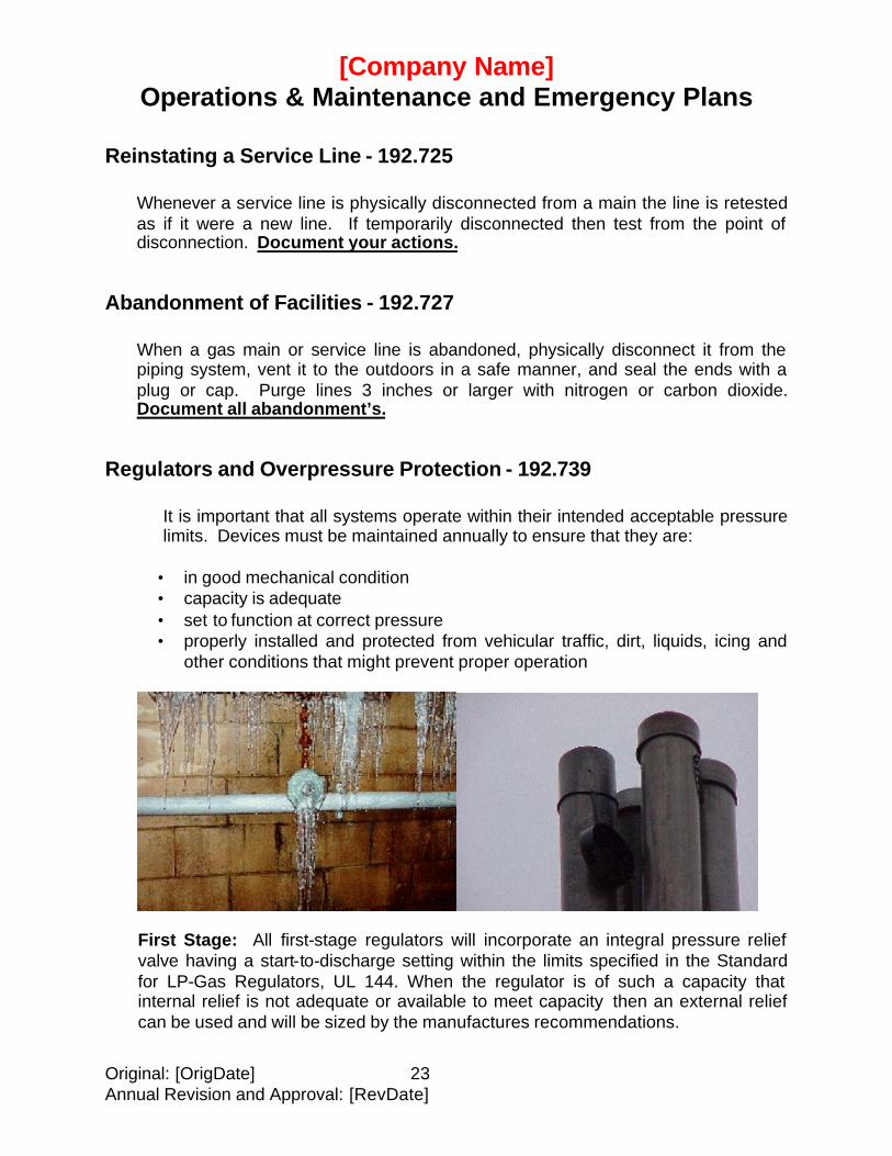
It is important that all systems operate within their intended acceptable pressure limits. Devices must be maintained annually to ensure that they are:
• in good mechanical condition • capacity is adequate • set to function at correct pressure • properly installed and protected from vehicular traffic, dirt, liquids, icing and
other conditions that might prevent proper operation
First Stage: All first-stage regulators will incorporate an integral pressure relief valve having a start-to-discharge setting within the limits specified in the Standard for LP-Gas Regulators, UL 144. When the regulator is of such a capacity that internal relief is not adequate or available to meet capacity then an external relief can be used and will be sized by the manufactures recommendations.
[Company Name] Operations & Maintenance and Emergency Plans
Original: [OrigDate] 24 Annual Revision and Approval: [RevDate]
Second Stage: [Insert Company Name] uses second-stage regulators with a maximum outlet pressure setting of 14 in. W.C. and are equipped with the following: An integral pressure relief valve on the outlet pressure side having a start-to-discharge pressure setting within the limits specified in the Standard for LP-Gas Regulators, UL 144. This relief device shall limit the outlet pressure of the second-stage regulator to 2.0 psi when the regulator seat disc is removed and the inlet pressure to the regulator is 10.0 psi or less as specified in the Standard for LP-Gas Regulators, UL 144. Regulators with a rated capacity of more than 500,000 Btu/hr can use a separate overpressure protection device complying with paragraphs 2.9.2 through 2.9.8 of the National Fuel Gas Code, NFPA 54 (ANSI Z223.1). The overpressure protection device shall limit the outlet pressure of the regulator to 2.0 psi when the regulator seat disc is removed and the inlet pressure to the regulator is 10 psi or less. High Pressure Regulator System: Whenever a high pressure regulator feeds multiple second stage regulators then the company will use a first stage regulator down stream of the high pressure regulator and upstream of the second stage regulators. If the high-pressure regulator has an overpressure protection device (either integral or separate), has a rated capacity of more than 500,000 Btu/hr and the second stage regulator incorporates an integral or separate overpressure protection device then the first stage regulator is not needed. This overpressure protection device for the second stage regulator will limit the outlet pressure of the second stage regulator to 2.0 psi when the regulator seat disc is removed and with an inlet pressure equivalent to the maximum outlet pressure setting of the high-pressure regulator. The company may use any of these installation methods. See systems report(s) to see what type of regulator setup the company used for a particular system. A sample Systems Report is included as Appendix C. The Systems Report is kept in the systems folder.
A. Install regulators in accordance with NFPA 58.
1. The system used is usually a two-stage system and never a single stage system.
2. Where considered necessary as a protection against system failure,
install (2) first-stage regulators in parallel to serve the storage or manifolded tanks. One of the regulators is to function as the primary and be set at the required distribution pressure; the second is to serve as the backup and be set at about 1 psi lower.
[Company Name] Operations & Maintenance and Emergency Plans
Original: [OrigDate] 25 Annual Revision and Approval: [RevDate]
3. Use regulators equipped with high capacity internal relief valves. If a
pressure regulator is not so equipped, install an in-line relief valve with the appropriate start-to-discharge pressure at the outlet of the regulator (See NFPA 58, Chapter 2).
4. Install a pressure gauge, or a fitting for inserting a gauge, downstream of
the first-stage regulator, for monitoring pressure, and performing a lock-up on the initial installation, and to verify regulator outlet delivery pressure(s) during the annual regulator inspection.
Inspect each high pressure regulator at least once each year, at intervals not to exceed (15) months, to determine its outlet pressure and its physical condition, to include the external surface, adjusting spring, vent opening, and the stability of its mounting. Record the results. In addition, the regulations require a test to be conducted annually to determine if the overpressure protection device (internal or external relief valve) is of sufficient capacity for the system, if feasible. If not feasible, a calculation must be made on an annual basis to ensure the capabilities of the relief device.
Key Valves - 192.747
A. Key valves are distribution line valves that are installed to shut down or isolate sections of the system in an emergency or for service. Install one at each high-pressure regulator, and at any other location appropriate for isolating piping sections. All valves must be readily accessible.
B. To prevent a potential hazard, do not operate a key valve without the full
understanding of its function. No valve should be opened where there is a pressure difference across the valve until the difference is fully understood and it is safe to open the valve.
C. Inspect and service each key valve according to the valves manufacturing
instructions, including the service valve on the storage tank(s), at least once each year, at intervals not to exceed 15 months. Ensure the handle is not “frozen”, the valve is free from leaks, the valve is readily accessible and ground movement is not creating a shear force on the connections. Record the results.
Maximum Allowable Operating Pressure
The high pressure or 1st stage lines should be operated at approximately 10 psi or at a pressure that will maintain the required pressure in the distribution lines, but will not operate at pressures over 15 psi that could cause re-liquefying in the lines. The
[Company Name] Operations & Maintenance and Emergency Plans
Original: [OrigDate] 26 Annual Revision and Approval: [RevDate]
1st stage regulator cannot be at a pressure that would be so high that if the second stage failed completely it would deliver more than two psi to the utilization equipment.
Pressure Test
Although NFPA 58 requires testing to be at the operating pressure or above, company policy requires testing must be at least [1-1/2] times the maximum operating pressure. All pressure tests shall be done according to appendix D of NFPA 54. Record results.
Accidental Ignition of Gas - 192.751
A. Take precautions to prohibit all sources of ignition from pedestrian, vehicular or other workplace hazards in areas where the presence of gas from leakage, purging or venting may constitute a hazard of fire or explosion. Use appropriate warning devices, signs and/or barricades, as necessary, route traffic as far away from the area as practical. Use non-sparking tools and lights that are approved for hazardous locations.
B. Vent gas during maintenance, servicing or purging only after potential sources of
ignition are removed, and in accordance with NFPA 58, Section 4.3. Use vertical stack. Use a flare stack for a controlled burn, if appropriate. If it is necessary to release a potentially hazardous mixture in a pit or trench, ensure you have constant ventilation, and you have a satisfactory CGI meter test before permitting work in the space. Ensure fire extinguishers are readily available.
C. Notify the local fire department when flaring or releasing more than minimal
quantities of gas. It is also good public relations to notify residences and businesses in the area when the flaring would attract attention or concern from the public.
D. When service is discontinued to a customer, close the service valve and secure it
with a lock or other device, or install a mechanical device or fitting that will prevent the flow of gas in the line to prevent unauthorized use or resumption of service.
Other Equipment
Other equipment installed or used in a gas system, such as, but not limited to, vaporizers, vapor meters, leak detectors, etc., should be listed or approved, and
[Company Name] Operations & Maintenance and Emergency Plans
Original: [OrigDate] 27 Annual Revision and Approval: [RevDate]
installed and operated in accordance with the manufacturer’s instructions and the authority having jurisdiction.
Manufacturers’ Literature
Manufacturers’ literature, to include specifications, installation and operating instructions should be maintained for all equipment installed and serviced in the gas system.
Maintenance Schedule
Maintain a schedule of maintenance, tests and inspections required. The schedule should be posted and available to all involved personnel. To determine the adequacy of existing procedures, documents of work performed, such as Service Work Orders will be reviewed by supervisors. Maintenance records are kept in the individual jurisdictional systems folders.
Procedures for Start-up and Shut-down
Start-up: To assure operation within established Maximum Allowable Operating Pressure limits for a particular system, and unless otherwise provided for in another section of this manual, no gas shall be introduced into a distribution line unless high pressure, or first stage, and fina l stage regulators, as well as overpressure protection devices, are installed in the piping.
Shutdown: System shutdown shall occur at the container(s) shut-off valve, and/or other key valves that are located upstream of a pressure regulating device, and overpressure protection device.
Corrosion Control - Subpart I
Aboveground Steel Piping and Tanks - 192.481
[Company Name] Operations & Maintenance and Emergency Plans
Original: [OrigDate] 28 Annual Revision and Approval: [RevDate]
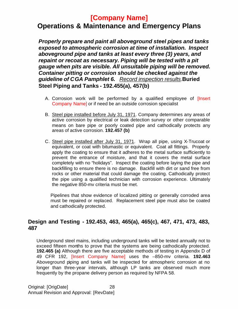
Properly prepare and paint all aboveground steel pipes and tanks exposed to atmospheric corrosion at time of installation. Inspect aboveground pipe and tanks at least every three (3) years, and repaint or recoat as necessary. Piping will be tested with a pit gauge when pits are visible. All unsuitable piping will be removed. Container pitting or corrosion should be checked against the guideline of CGA Pamphlet 6. Record inspection results.Buried Steel Piping and Tanks - 192.455(a), 457(b)
A. Corrosion work will be performed by a qualified employee of [Insert
Company Name] or if need be an outside corrosion specialist
B. Steel pipe installed before July 31, 1971. Company determines any areas of active corrosion by electrical or leak detection survey or other comparable means on bare pipe or poorly coated pipe and cathodically protects any areas of active corrosion. 192.457 (b)
C. Steel pipe installed after July 31, 1971. Wrap all pipe, using X-Trucoat or equivalent, or coat with bitumastic or equivalent. Coat all fittings. Properly apply the coating to ensure that it adheres to the metal surface sufficiently to prevent the entrance of moisture, and that it covers the metal surface completely with no “holidays”. Inspect the coating before laying the pipe and backfilling to ensure there is no damage. Backfill with dirt or sand free from rocks or other material that could damage the coating. Cathodically protect the pipe using a qualified technician with corrosion experience. Ultimately the negative 850-mv criteria must be met.
Pipelines that show evidence of localized pitting or generally corroded area must be repaired or replaced. Replacement steel pipe must also be coated and cathodically protected.
Design and Testing - 192.453, 463, 465(a), 465(c), 467, 471, 473, 483, 487
Underground steel mains, including underground tanks will be tested annually not to exceed fifteen months to prove that the systems are being cathodically protected. 192.465 (a) Although there are five acceptable methods of testing in Appendix D of 49 CFR 192, [Insert Company Name] uses the –850-mv criteria. 192.463 Aboveground piping and tanks will be inspected for atmospheric corrosion at no longer than three-year intervals, although LP tanks are observed much more frequently by the propane delivery person as required by NFPA 58.
[Company Name] Operations & Maintenance and Emergency Plans
Original: [OrigDate] 29 Annual Revision and Approval: [RevDate]
For more information on corrosion and compliance refer to 49 CFR Part 192 Subpart I and CHAPTER VIII of The Training Guide for Operators of Small LP-Gas Systems.
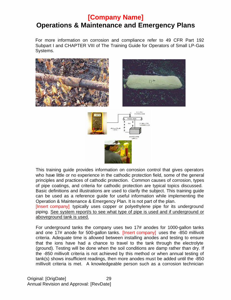
This training guide provides information on corrosion control that gives operators who have little or no experience in the cathodic protection field, some of the general principles and practices of cathodic protection. Common causes of corrosion, types of pipe coatings, and criteria for cathodic protection are typical topics discussed. Basic definitions and illustrations are used to clarify the subject. This training guide can be used as a reference guide for useful information while implementing the Operation & Maintenance & Emergency Plan. It is not part of the plan. [Insert company] typically uses copper or polyethylene pipe for its underground piping. See system report/s to see what type of pipe is used and if underground or aboveground tank is used. For underground tanks the company uses two 17# anodes for 1000-gallon tanks and one 17# anode for 500-gallon tanks. [Insert company] uses the -850 millivolt criteria. Adequate time is allowed between installing anodes and testing to ensure that the ions have had a chance to travel to the tank through the electrolyte (ground). Testing will be done when the soil conditions are damp rather than dry. If the -850 millivolt criteria is not achieved by this method or when annual testing of tank(s) shows insufficient readings, then more anodes must be added until the -850 millivolt criteria is met. A knowledgeable person such as a corrosion technician
[Company Name] Operations & Maintenance and Emergency Plans
Original: [OrigDate] 30 Annual Revision and Approval: [RevDate]
(may be an outside consultant) will design larger tank installations for anode amount and placement. 192.453
1. [Omit the following if no rectifiers are used.] All rectifier reverse current
switches, diodes and interference bonds whose failure would cause system failure will be inspected and electrically tested for proper performance. Testing will be done at least (6) times a year, with intervals not to exceed 2-1/2 months. All other interference bonds will be tested each calendar year not to exceed fifteen months. 192.465 (c) Record the results.
2. Company will cathodically protect all steel pipe and tanks installed
underground after July 31, 1971, in addition to the corrosion protection prescribed above, using anode bags or a rectifier system that will maintain a negative voltage of at least –0.85 volt, with reference to a saturated copper-copper sulfate half cell. Cathodically protect tanks that are underground or mounded by including them in the protective system for the pipe, or isolate them with insulating fittings and protect them separately. Establish test points, as appropriate for the system, to periodically determine the adequacy of the cathodic protection through electrical measurements. 192.463
3. Install an insulating fitting above ground, upstream of the vapor meter, to
isolate the protected underground piping. If above ground storage tank(s) are used, install an insulating fitting when necessary to join dissimilar metals underground. 192.467
4. Test lead wires will be connected to the pipeline or tank so as to remain
mechanically secure and electrically conductive. These connections will be observed during annual corrosion testing. In some cases testing is done directly to a tank fitting. 192.471
5. For valid interpretation of the voltage measurement, voltage (IR) drops other
than those across the structure-electrolyte boundary must be considered. When testing an underground tank, readings not directly over the anodes shall be at least –850-mv.
6. Whenever an underground system is installed, careful consideration will be
given to locate the system against stray currents. Any existing systems that are having problems with stray currents will be evaluated and remedial action will be taken. All cathodically protected systems will be installed with consideration to minimize harm to other underground systems in the immediate area. 192.473
7. Whenever a section of pipeline is removed from a system due to corrosion,
the replaced section will be properly prepared and a suitable coating will be applied and will be cathodically protected. 192.483
[Company Name] Operations & Maintenance and Emergency Plans
Original: [OrigDate] 31 Annual Revision and Approval: [RevDate]
8. All general and localized corrosion will be evaluated visually or if there are
pits with a pit gauge. If after gauging it is discovered that the remaining wall thickness is not sufficient to support the maximum allowable pressure of the pipe or the remaining wall thickness is less than 30 percent of the named wall thickness, then pipe will be replaced. 192.487
Inspection of Exposed Underground Pipe - 192.459
Whenever any buried pipeline is exposed for any reason, inspect it for evidence of external corrosion. Where there is general or localized corrosion to the extent that leakage might result, repair or replace the pipe. Where corrosion has reduced the wall thickness to less than 30% of the nominal thickness, replace the pipe. Coat or wrap and catholically protect any replacement or repaired pipe. Record the results.
Internal Inspection of Pipe - 192.475
Whenever steel pipe is removed for any reason, inspect the internal surface for corrosion. If internal corrosion is found, investigate the adjacent sections of pipe. Where general corrosion or pitting is found and is such that leakage might result, replace the pipe in accordance with the section above. Record the results.
[Company Name] Operations & Maintenance and Emergency Plans
Original: [OrigDate] 32 Annual Revision and Approval: [RevDate]
EMERGENCY PLAN - 192.615
Designated employees are to be trained in response to emergencies that may occur on jurisdictional gas systems. These emergencies may include, but are not limited to, the following:
A. Uncontrolled leaks considered hazardous. B. Fire or explosion. C. Failure of or danger to major segments of the system. D. Natural disasters (floods, tornadoes, hurricanes, earthquakes, heavy snow
fall, etc.) E. Interruption of gas service.
F. Civil disturbance (riots, etc.)
Training Will Be Documented and Made Available. - 192.615(b) (2)
No emergency plan can cover all situations and conditions. There is no substitute for sound judgment by the persons involved. In any emergency, the safety of people is the highest priority.
General emergency planning is provided below. [Modify or amend these plans to meet your situation and capabilities. In addition, the information that is specific for each system should contain directions and requirements for various emergencies. (An example would be location of emergency valves).]
Pre-Planning – 192.615(a) (2), 615(b) (1), 615(b) (2), 615(b) (3), 615(c) (3)
A. A review of this Manual will occur at least once a year and any changes will be issued and reviewed with the proper personnel. This includes both management and emergency response employees. 192.615 (b)(1), (b)(2)
B. Maintain liaison with the appropriate public officials, including police, fire
departments, local emergency response groups and hospitals with respect to emergency procedures. This liaison will be periodic personal contact to discuss the appropriate operations and the response talents of all parties that could be involved in an emergency. New information and/or requirements will be
[Company Name] Operations & Maintenance and Emergency Plans
Original: [OrigDate] 33 Annual Revision and Approval: [RevDate]
discussed and verification of all participants contact methods made (i.e. home, office, pager, numbers etc.). Provide training to various organizations. 192.615(a) (2), 192.615 (b) (3) (c) (3) See also 192.616.
Training for Fire Departments
Training for fire departments is a must. Appropriate fire departments should be approached at least annually for training of their new personnel and refresher training for others. The training should cover as a minimum.
A. Propane properties, as they affect fire personnel. Operation of container
valves. B. Emergency responses as outlined in the Emergency Response Procedures.
Emergency Telephone Numbers
Post emergency telephone numbers for police, fire, hospital, burn center, emergency response group, etc., on the telephones or in a highly visible location in the District Office. Use 911 if that is the proper emergency number for your location.
[Insert Emergency Telephone List]
Post emergency contact telephone numbers on plant gates for public use.
Ensure there is a positive method of contacting emergency personnel outside of working hours. Use an answering service or machine that directs the caller to a specific emergency contact. Ensure there is a qualified emergency employee on-call whenever the office is closed.
Have an internal emergency response list of personnel with names and telephone numbers prioritized.
[Insert List of Personnel Names and Telephone Numbers prioritized]
Maintain all repair equipment necessary to control an emergency in a location that is known to, and accessible to, all employees at any time, and ensure that appropriate employees know how to use the equipment that may be required from other sources.
[Company Name] Operations & Maintenance and Emergency Plans
Original: [OrigDate] 34 Annual Revision and Approval: [RevDate]
Discuss the various types of emergencies that could occur with the appropriate personnel. Provide each new customer with packet containing information on odorization and procedures to follow in the event of a gas leak and a 24-hour emergency telephone number.
Each employee who delivers propane or installs or services the gas system should be alert to any unsafe or potentially unsafe condition or procedure that may be encountered. Correct the problem, if possible; if not, take action, to include shutting off the gas supply to the area, and report the situation to the appropriate personnel.
Response to Emergencies – 192.615(a)(8), 615(a)(10)
A. When responding to an emergency, the [insert company name] designated qualified employee at the scene should take charge of actions to eliminate or bring the hazard under control, as outlined in the Emergency Response Procedures.
B. If fire or other emergency response personnel are on the scene, the [insert
company name person] is to identify him (her) self to the person in charge and provide information and assistance as may be required. 192.615 (a)(8)
C. [Insert company name] will conduct an investigation of its own as soon as
possible after an incident. All appropriate personal will be provided procedures to follow as soon as possible after an incident. In some cases an independent consultant may be hired to assist in the investigation. Results of any incident will be critiqued so that future incidents may be prevented. 192.615 (a)(10), 192.617
Emergency Response Procedures – 192.615(a)(1)
When any call is received it is identified and then classified. 192.615 (a)(1) The following are minimum responses by emergency personnel:
NOTE: Gas leaks are to be handled immediately. Gas service is not to be re-established until leaks are corrected and leak tests are satisfactorily performed.
1. First Notification of an Emergency During Working Hours.
A. The person receiving the report is to obtain as much information as possible to enable the responding service person to better understand the situation; however, use common sense and consider possible danger to life and property when holding the caller on the telephone.
[Company Name] Operations & Maintenance and Emergency Plans
Original: [OrigDate] 35 Annual Revision and Approval: [RevDate]
B. In the case of a possible gas leak, advise the caller to:
1) Evacuate the building or area. 2) Extinguisher all open flames, including appliance burners, pilots
and smoking material. 3) NOT to operate any electrical switches or thermostats, ring
doorbells; use the telephone or light matches or lighters.
4) NOT to start a vehicle if the gas leak is outside.
5) Notify the resident manager or maintenance person.
C. Dispatch qualified [Insert company name] personnel to the scene.
D. Call the fire department (911) or other appropriate officials if the initial report dictates.
First Notification of an Emergency – 192.615(a)(4)
A. Obtain as much information as possible; however, use common sense and consider potential danger to life and property when holding the caller on the telephone.
B. In the case of a possible gas leak, inform the caller of the safety precautions as
outlined above.
C. Notify the fire department (911) and/or appropriate officials if the initial situation report dictates. See notification list.
D. Take all of the equipment to the scene that is considered necessary. If you will
need assistance, either at the scene or in gathering the necessary equipment, request it from the appropriate management or call other employees directly. If specialized equipment is needed call from the list provided from PGANE. 192.615 (a)(4)
[Insert Equipment List, Company Owned By and Telephone Numbers]
Leaks With Ignition (gas fire) - 192.615(a)(3)(ii), 615(a)(7)
Take the following action until the situation is corrected or until the fire department takes charge.
[Company Name] Operations & Maintenance and Emergency Plans
Original: [OrigDate] 36 Annual Revision and Approval: [RevDate]
A. Always protect people first and then property.
B. Keep bystanders well away from the scene. Assist with evacuation if
requested by the person in charge. In the absence of the fire department or other emergency group, if tank failure appears probable to you, require evacuation to a minimum of 2000 feet (approx. ½ mile) from the tank.
C. Stay upwind and isolate the leak by shutting off the gas at the storage tank or
at a line valve. DO NOT EXTINGUISH THE FIRE UNTIL THE LEAK HAS BEEN STOPPED.
D. Eliminate or reduce the exposure of portable containers to heat from the fire
by removing them, if possible.
E. If the tank is involved in the fire, apply water, if available, to the top of the tank to cool the metal and keep the pressure down.
Leaks Without Ignition - 192.615(a)(3)(i), 615(a)(5), 615(a)(6) (detected inside or near a building)
A. Determine the danger of the leak using the appropriate equipment.
B. Evacuate people if necessary. Always protect life first and then property.
C. Stay up wind and isolate the leak by shutting off the gas supply at the tank or a line valve, upstream of the leak. If the location of the leak cannot be readily determined or there are multiple leaks, shut off the valve on the storage tank.
D. Eliminate and prevent ignition sources in the area and downwind of the leak, to
include vehicle traffic, smoking, non-explosion-proof flashlights, cell phones or other lights, flares, lighted appliances in buildings downwind of the leak, etc.
E. Use a water mist spray, if available, to increase the dissipation of the vapor
aboveground.
Explosion Near or On a Jurisdictional System - 192.615(a)(3)(iii) Again: Protect life first and then property before an investigation begins to identify cause.
Natural Disasters - 192.615(a)(3)(iv)
[Company Name] Operations & Maintenance and Emergency Plans
Original: [OrigDate] 37 Annual Revision and Approval: [RevDate]
Generally, the hazards that can be expected are containers floating away, containers knocked off their bases and pipeline failures. Primary actions include:
A. Give priority to the control of any leaks.
B. Shut off the valves on containers that have broken loose. Inspect the
containers for damage. Reset the containers or return them to [insert plant? District yard? Etc.]. Drain the containers of any water. Purge the container and treat with methanol before using.
C. Inspect piping, regulators and meters for damage. Make necessary repairs or
replacements. If the damage cannot be corrected at the time, isolate and lock off the affected portion of the system.
Civil Disturbances
The hazards generally encountered are from vandalism and may involve broken lines, open valves or damaged regulators and meters.
A. Give priority to the control of any leaks.
B. Make repairs. If repairs cannot be made at the time, isolate and lock off the
affected portions of the system.
Damage to Major Segments of the System
Generally, others digging and damaging the piping cause this type of damage.
A. Isolate the damaged sections. Make repairs. If repairs cannot be made at the time, lock off the isolated sections until repairs can be made. Ensure the remaining portions of the piping system are leak-free.
B. Make sure there is no flammable concentration of gas pocketed in ditches of
low-lying areas.
Blasting
A. When you are aware of any blasting having been done in the vicinity of the gas system, survey the system to determine if there is any evidence of a leak or other damage. Respond to any hazardous conditions as outlined elsewhere in this Section.
[Company Name] Operations & Maintenance and Emergency Plans
Original: [OrigDate] 38 Annual Revision and Approval: [RevDate]
Interruption of Gas Supply - 192.615(a)(9)
A. The primary objective is to determine the reasons for the interruption and correct the problem. Respond to any hazardous conditions as outlined elsewhere in this Section.
B. Gas service is not to be resumed until conditions are corrected for safe
operation, and all pressure/leak tests are satisfactorily performed. C. When restoring service to a system serving multiple customers, service is to be
restored on a house-to-house basis. Shut each customer off at the service riser. Purge the lines, if necessary. Conduct a leak check of all service and house lines, using a water manometer and/or block gauge. If you cannot get into a house or metered service because the customer is not at home, do not restore service. Lock the customer’s service off and leave a [insert name of notice indicating that you could not get in] in a conspicuous place requesting the customer to contact the gas company for restoring service.
Rules Applying to All of the Above Emergencies – 192.617
A. When working with any gas leaks, make sure the area is kept free of ignition sources.
B. When repairs have been made, make sure the area is free of flammable
concentrations of gas, inside and outside of buildings in the area, using an quantitative combustible gas indicator.
C. When repairs have been made to damaged piping, ensure the affected sections
are leak-free before re-introducing gas. If repairs cannot be made to any part of the system at the time, the affected sections are to be made safe until permanent repairs can be made.
D. Where appropriate, and under the direction of the [insert company name] Legal
Department, failed equipment should be sent to a laboratory for examination for the purpose of determining the cause(s) of the failure and minimize the possibility of recurrence. 192.617
Reporting Accidents
All accidents and incidents are to be reported in accordance with the reporting procedures in this manual.
[Company Name] Operations & Maintenance and Emergency Plans
Original: [OrigDate] 39 Annual Revision and Approval: [RevDate]
Media Contact, Public and Private Statements
No statement or release of any specific info rmation is to be given without authorization from the [Insert title of appropriate personnel].
Review of Emergency Response Plans - 192.615(b)(3)
After each emergency, whether actual or simulated, conduct a review of the procedures followed to determine if the emergency response plan was effective.
Public Education - (192.616)
All new and existing customers, the public, appropriate government officials and persons engaged in excavation will receive information explaining actions to be taken in the event of an emergency, such as notifying the [Insert company name] or appropriate public officials. This information will be given by mail distribution on an annual basis. Notification of all jurisdictional accounts will be given as needed, either by mail or in person, to all other appropriate officials. The information will be delivered through this or other media in all areas where the company has jurisdictional accounts.
[Company Name] Operations & Maintenance and Emergency Plans
Original: [OrigDate] 40 Annual Revision and Approval: [RevDate]
APPENDIX A
LEAKAGE SURVEYS AND METHODS OF GAS LEAK DETECTION
A leakage survey must be conducted over each pipeline system at intervals not exceeding 15 months, but at least once each calendar year.; Areas surveyed should be marked on a map of the distribution system, with the approximate location of each leak found.
(a) Where the following may be present, the frequency of the survey should be
increased.
1. Material makeup of system. Certain materials may develop a higher than average leakage rate, such as unprotected steel pipe and coated steel pipe not under cathodic protection;
2. Age of pipe (over 20 years) and corrosive soil environment;
3. Pipe having a previous history of excessive leakage and the cause(s)
have yet to be eliminated;
4. Pipelines in, under, or near buildings, especially schools, churches, hospitals, or other buildings having a high concentration of people;
5. Pipelines located in areas of construction, blasting or recent heavy
weight traffic. Pipe located in crawl spaces under apartment buildings or mobile homes; and
6. Service lines in or under buildings and meters in buildings.
Available openings for finding leaks include water, sewer, electric, and telephone lines; manholes; cracks in pavement; and hollow walls (cinder block construction) in areas near gas piping.
When conducting these surveys check for leaks near the gas pipe entrance, both inside and outside the buildings. If a leak is discovered, it must be investigated to determine if a hazardous condition exists. If so, immediate action must be taken, to include shutting off the gas system, if necessary, and the leak repaired.
[Company Name] Operations & Maintenance and Emergency Plans
Original: [OrigDate] 41 Annual Revision and Approval: [RevDate]
Warning Signs of a Leak
Odor: Gas is intentionally odorized so the average person can perceive it at a concentration well below the explosive range. Gas odor is the most common and effective indication of a leak. A report of gas odor should be investigated immediately, the leak found, and repaired if possible. In any case classify the leak and make sure that all Class I leaks are either repaired or reduced to a level of acceptable safety and scheduled for repair. This odorant may be filter out as it passes through soil. It may also be modified by passing through soil and into sewage systems containing vapors or fumes from other combustibles, as well as the sewage odor itself. Therefore, odor is not always totally reliable as an indicator of the presence or absence of gas leaks. Nevertheless, in making maintenance rounds, always be alert for the smell of gas. Vegetation: Vegetation in an area of gas leakage may improve or deteriorate, depending on the soil; the surveys of changes in vegetation may indicate slow sub-soil leaks. Vegetation surveys should be supplemented with instrumentation.
Insects: Insects migrate to points or areas of leakage. They seem to like the smell of the gas odorant. Checks for heavy insect activity, particularly near the riser, the gas meter and regulator should be made. Fungus-like Growth: Such growth in valve boxes, manholes, etc., may indicate gas leakage. The color of the growth is generally white or grayish-white and looks like a coating of frost. Sound: Listen for leaks. A hissing sound at a bad connection, a fractured pipe or a corrosion pit hole is the usual indication of a gas leak.
Unaccounted for Gas or Unusual Increase in Delivery: A possible gas leak may be indicated when there is an unusual shortage when reconciling inventory or when it is noted that the gallons delivered have an unusual increase over previous deliveries without any known reason.
Qualification of Personnel
Gas leakage surveys should be performed by personnel who are qualified by training and experience in the type of survey being performed. They should be thoroughly familiar with the characteristics of the petroleum gas in the system and trained in the use of leakage detection instruments.
[Company Name] Operations & Maintenance and Emergency Plans
Original: [OrigDate] 42 Annual Revision and Approval: [RevDate]
Reports from Outside Sources
Any notification from an outside source (such as police or fire department, other utility, contractor, customer or general public) reporting an odor, leak, explosion or fire which may involve gas pipelines or other gas facilities should be investigated promptly. If the investigation reveals a leak, the leak should be graded and action should be taken in accordance with these guidelines.
Odors or Indications from Foreign Sources
When leak indications (such as gasoline vapors, natural, petroleum, sewer or marsh gas) are found to originate from a foreign source or facility or customer owned piping, prompt actions should be taken where necessary to protect life and property. Potentially hazardous leaks should be reported promptly to the operator of the facility and, where appropriate, to the police department, fire department or other governmental agency. When the company's pipeline is connected to a foreign facility (such as the customer's piping), necessary action (such as disconnecting or shutting off the flow of gas to the facility) should be taken to eliminate the potential hazard.
Leakage Surveys and Test Methods
For leakage surveys, see the limitations under 192.723 regarding leak detection equipment. The following gas leakage surveys and test methods may be employed, as applicable, in accordance with written procedures.
• Sub-surface gas detector survey (including bar-hole surveys) • Bubble leakage test • Pressure drop test
Other survey and test methods may be employed if they are deemed appropriate and are conducted in accordance with procedures, which have been tested and proven to be at least equal to the methods listed in this section.
The surface gas detection survey and vegetation survey methods used for natural gas systems are not recommended for use on petroleum gas systems. Petroleum gases are heavier than air and will frequently not come to the ground surface or cause surface indications in the vegetation. However, the surface gas detection survey, when properly conducted by taking into account that the gas is heavier than air, may be used adjacent to aboveground facilities.
[Company Name] Operations & Maintenance and Emergency Plans
Original: [OrigDate] 43 Annual Revision and Approval: [RevDate]
(a) Sub-surface gas detection survey
1. Definition. The sampling of the sub-surface atmosphere with a combustible gas indicator or other device capable of detecting 10 percent of the LEL at the sample point.
2. Procedure. The survey should be conducted by performing tests with a
series of bar holes immediately adjacent to the gas facility and in available openings (confined spaces and small substructures) adjacent to the gas facility. The location of the gas facility and its proximity to buildings and other structures should be considered when determining the spacing of sample points. Spacing of sample points along the main or pipeline will depend on soil and surface conditions but should never be more than 20 feet apart. Where the facility passes under paving for a distance of 20 feet or less, tests should be made at the entrance and exit points of the paved area. Where the paved area over the facility is 20 feet or greater in length, sample points should be located at intervals of 20 feet or less. In the case of extensive paving, permanent test points should be considered, particularly in low places. The sampling pattern should include tests at potential leak locations such as threaded or mechanical joints and at building walls at the service riser or service line entrance. All available openings adjacent to the facility should be tested.
When testing available openings for petroleum gas, readings should be taken at both the top and bottom of the structure. When testing larger confined spaces or basements, the floor areas including floor drains should be thoroughly tested because petroleum gases can lie temporarily in pockets containing explosive mixtures. Since migrating gas may not enter at the pipeline entrance, a perimeter survey of the floors and walls is recommended. When conducting the survey, all bar holes should penetrate to the approximate same depth in order to obtain consistent and worthwhile readings. This includes penetrating through capping materials such as paving, concrete, frost or surface sealing by ice or water. The required depth of the bar hole will also depend upon the soil conditions, the depth of and pressure in the pipeline and the type of instrument being used. The readings should be taken at the bottom of the bar hole. The probe used should be equipped with a device to preclude the drawing in of fluids. When conducting the survey, the inspector should use the most sensitive scale on the instrument, watching for small indications of combustible gas. Any indication should be further investigated to determine the source of the gas. Care should be taken to avoid damaging the pipe or coating with the probe bar.
3. Utilization. This survey method should be utilized for buried facilities. Good
judgment should be used to determine when the recommended spacing of
[Company Name] Operations & Maintenance and Emergency Plans
Original: [OrigDate] 44 Annual Revision and Approval: [RevDate]
sample points is inadequate. Additional sample points should be provided under these conditions. Available openings (such as manholes, vaults and valve boxes) should be tested. However, they should not be relied upon as the only points used to test for petroleum gas leakage.
(b) Bubble leakage test
(1) Definition. The application of a soap-water or other bubble forming solutions
on exposed piping to determine the existence of a leak.
(2) Procedure. The exposed piping systems should be reasonably cleaned and completely coated with the solution. Leaks are indicated by the presence of bubbles. The bubble forming solution should not be used on piping unless it has been determined by investigation or test that the piping is adequately resistant to direct contact with the solution.
(3) Utilization. This test method may be used for the following:
i) Testing exposed above ground portions of a system (such as meter set assemblies or exposed piping on bridge crossings).
ii) Testing a tie-in joint or leak repair, which is not included in a
pressure test.
(c) Pressure drop test
(1) Definition. A test to determine if an isolated segment of pipeline loses pressure due to leakage.
(2) Procedure. Facilities selected for pressure drop tests should first be isolated
and then tested. The following criteria should be considered in determining test parameters:
(i) Test pressure. A test conducted on existing facilities solely for the
purpose of detecting leakage should be performed at a pressure at least equal to the operating pressure.
(ii) Test medium. Propane. (iii) Test duration. The duration of the test should be of sufficient length
to detect leakage. The following should be considered in the determination of the duration:
• The volume under test.
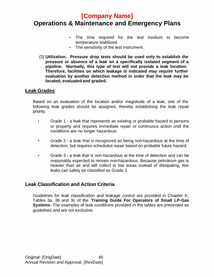
[Company Name] Operations & Maintenance and Emergency Plans
Original: [OrigDate] 45 Annual Revision and Approval: [RevDate]
• The time required for the test medium to become temperature stabilized.
• The sensitivity of the test instrument.
(3) Utilization. Pressure drop tests should be used only to establish the pressure or absence of a leak on a specifically isolated segment of a pipeline. Normally, this type of test will not provide a leak location. Therefore, facilities on which leakage is indicated may require further evaluation by another detection method in order that the leak may be located, evaluated and graded.
Leak Grades
Based on an evaluation of the location and/or magnitude of a leak, one of the following leak grades should be assigned, thereby establishing the leak repair priority.
• Grade 1 - a leak that represents an existing or probable hazard to persons
or property and requires immediate repair or continuous action until the conditions are no longer hazardous.
• Grade 2 - a leak that is recognized as being non-hazardous at the time of
detection, but requires scheduled repair based on probable future hazard. • Grade 3 - a leak that is non-hazardous at the time of detection and can be
reasonably expected to remain non-hazardous. Because petroleum gas is heavier than air and will collect in low areas instead of dissipating, few leaks can safely be classified as Grade 3.
Leak Classification and Action Criteria
Guidelines for leak classification and leakage control are provided in Chapter X, Tables 3a, 3b and 3c of the Training Guide For Operators of Small LP-Gas Systems. The examples of leak conditions provided in the tables are presented as guidelines and are not exclusive.

Original: [OrigDate] 46 Annual Revision and Approval: [RevDate]
APPENDIX B - FORMS
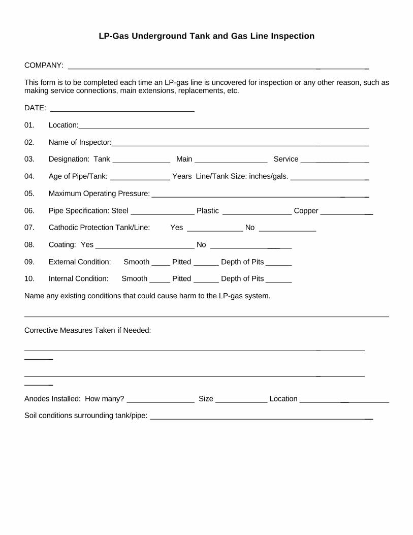
LP-Gas Underground Tank and Gas Line Inspection COMPANY: _ _ This form is to be completed each time an LP-gas line is uncovered for inspection or any other reason, such as making service connections, main extensions, replacements, etc. DATE: 01. Location: _ _ 02. Name of Inspector: _ _ 03. Designation: Tank Main Service ________ _ 04. Age of Pipe/Tank: Years Line/Tank Size: inches/gals. _ 05. Maximum Operating Pressure: _ _ 06. Pipe Specification: Steel Plastic Copper __ 07. Cathodic Protection Tank/Line: Yes No 08. Coating: Yes No ___ 09. External Condition: Smooth Pitted Depth of Pits 10. Internal Condition: Smooth Pitted Depth of Pits Name any existing conditions that could cause harm to the LP-gas system. Corrective Measures Taken if Needed: _ _ _ _ Anodes Installed: How many? Size Location __ Soil conditions surrounding tank/pipe: __
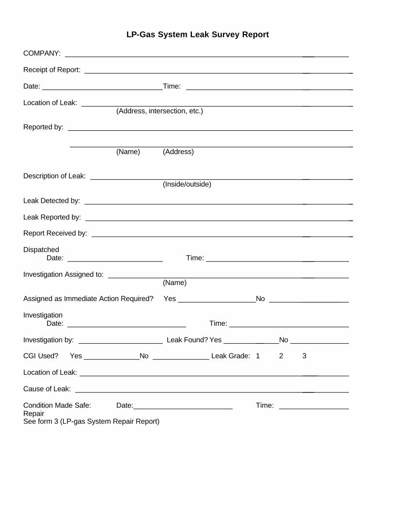
LP-Gas System Leak Survey Report COMPANY: ___ Receipt of Report: __ _ Date: Time: __ _ Location of Leak: __ _ (Address, intersection, etc.) Reported by: _ _ (Name) (Address) Description of Leak: __ _ (Inside/outside) Leak Detected by: _ _ Leak Reported by: _ Report Received by: __ _ Dispatched Date: Time: ___ Investigation Assigned to: ___ (Name) Assigned as Immediate Action Required? Yes No __________ Investigation Date: Time: ____ Investigation by: Leak Found? Yes __ No CGI Used? Yes No Leak Grade: 1 2 3 Location of Leak: ____ Cause of Leak: ___ Condition Made Safe: Date: Time: Repair See form 3 (LP-gas System Repair Report)
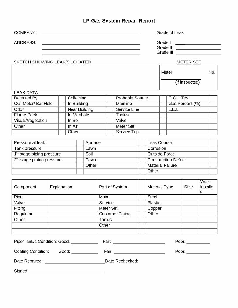
LP-Gas System Repair Report COMPANY: Grade of Leak ADDRESS: Grade I ____
Grade II Grade III
SKETCH SHOWING LEAK/S LOCATED METER SET
Meter No. ___________ (if inspected)
LEAK DATA Detected By Collecting Probable Source C.G.I. Test CGI Meter/ Bar Hole In Building Mainline Gas Percent (%) Odor Near Building Service Line L.E.L. Flame Pack In Manhole Tank/s Visual/Vegetation In Soil Valve Other In Air Meter Set Other Service Tap Pressure at leak Surface Leak Course Tank pressure Lawn Corrosion 1st stage piping pressure Soil Outside Force 2nd stage piping pressure Paved Construction Defect Other Material Failure Other Component
Explanation
Part of System
Material Type
Size
Year Installed
Pipe Main Steel Valve Service Plastic Fitting Meter Set Copper Regulator Customer Piping Other Other Tank/s Other Pipe/Tank/s Condition: Good: Fair: Poor: Coating Condition: Good: Fair: Poor: Date Repaired: Date Rechecked: Signed: _
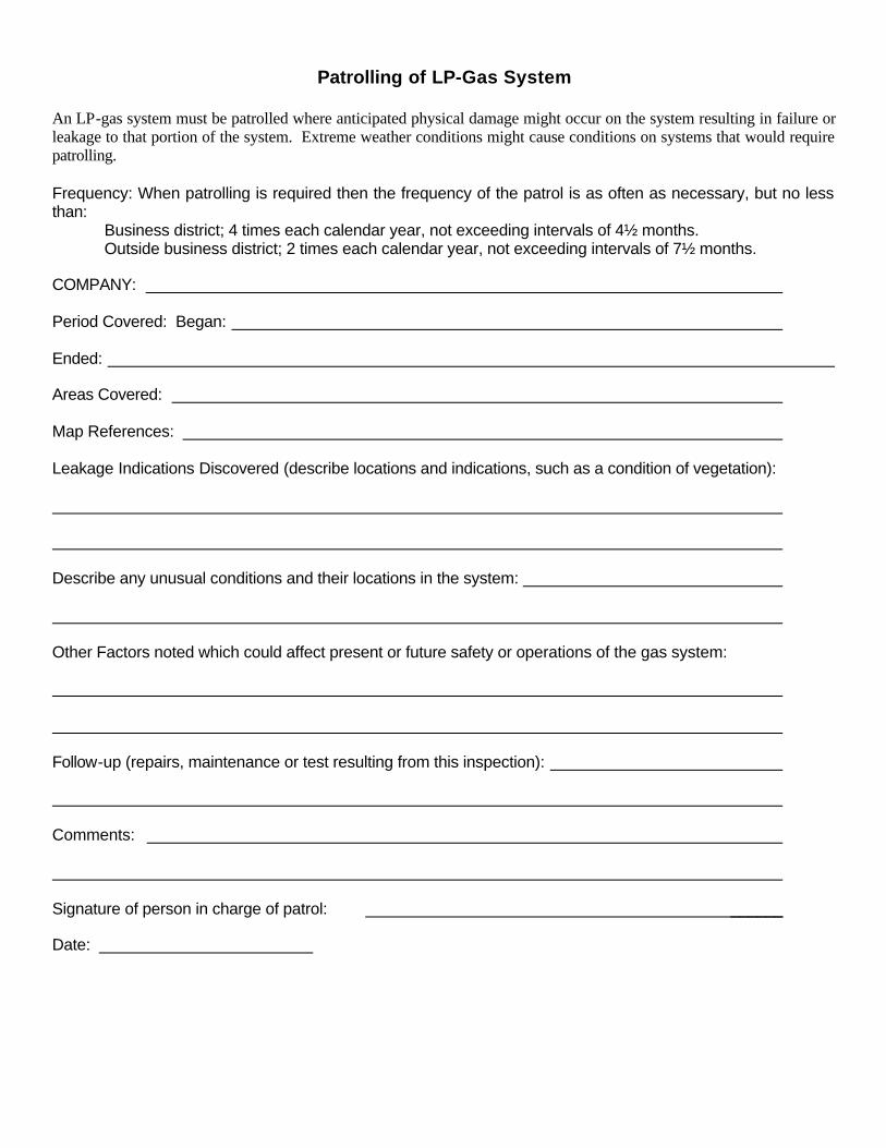
Patrolling of LP-Gas System An LP-gas system must be patrolled where anticipated physical damage might occur on the system resulting in failure or leakage to that portion of the system. Extreme weather conditions might cause conditions on systems that would require patrolling. Frequency: When patrolling is required then the frequency of the patrol is as often as necessary, but no less than: Business district; 4 times each calendar year, not exceeding intervals of 4½ months.
Outside business district; 2 times each calendar year, not exceeding intervals of 7½ months. COMPANY: Period Covered: Began: Ended: Areas Covered: Map References: Leakage Indications Discovered (describe locations and indications, such as a condition of vegetation): Describe any unusual conditions and their locations in the system: Other Factors noted which could affect present or future safety or operations of the gas system: Follow-up (repairs, maintenance or test resulting from this inspection): Comments: Signature of person in charge of patrol: ______ Date:
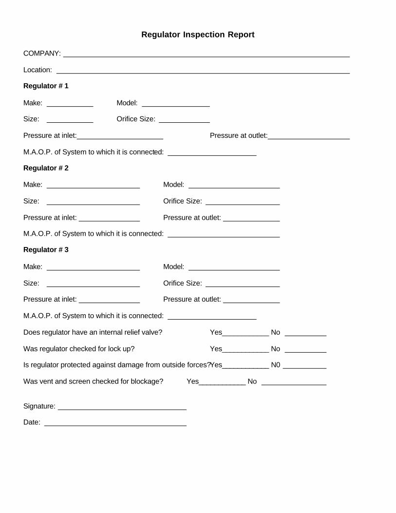
Regulator Inspection Report COMPANY: Location: Regulator # 1 Make: Model: Size: Orifice Size: Pressure at inlet: Pressure at outlet: M.A.O.P. of System to which it is connected: Regulator # 2 Make: Model: Size: Orifice Size: Pressure at inlet: Pressure at outlet: M.A.O.P. of System to which it is connected: Regulator # 3 Make: Model: Size: Orifice Size: Pressure at inlet: Pressure at outlet: M.A.O.P. of System to which it is connected: Does regulator have an internal relief valve? Yes____________ No Was regulator checked for lock up? Yes____________ No Is regulator protected against damage from outside forces?Yes____________ N0 Was vent and screen checked for blockage? Yes____________ No Signature: Date:
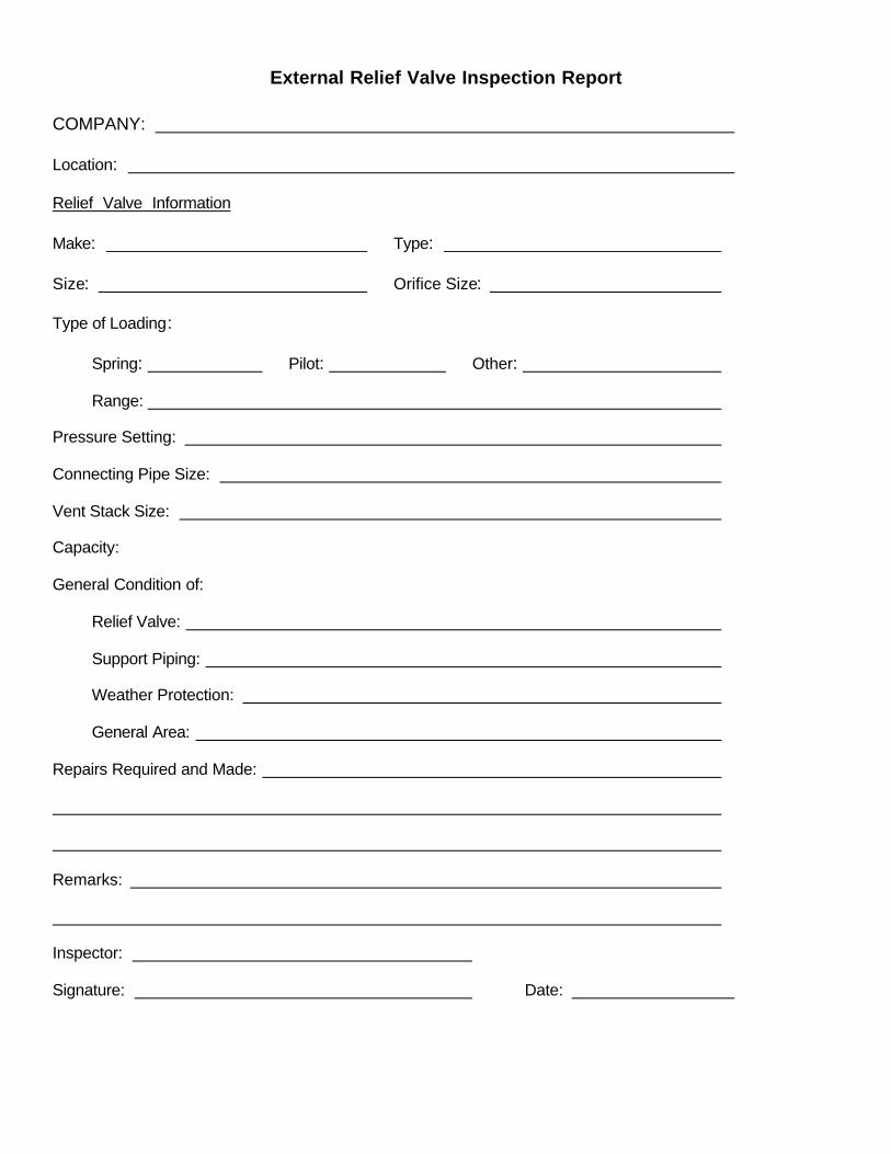
External Relief Valve Inspection Report COMPANY: Location: Relief Valve Information Make: Type: Size: Orifice Size: Type of Loading: Spring: Pilot: Other: Range: Pressure Setting: Connecting Pipe Size: Vent Stack Size: Capacity: General Condition of: Relief Valve: Support Piping: Weather Protection: General Area: Repairs Required and Made: Remarks: Inspector: Signature: Date:
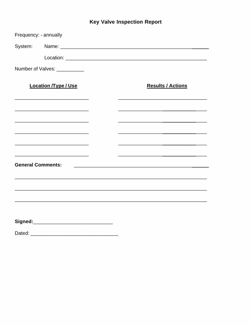
Key Valve Inspection Report Frequency: - annually System: Name: ______ Location: Number of Valves: __________ Location /Type / Use Results / Actions ____________ ____________ ____________ ____________ ____________ General Comments: ______ Signed:_____________________________ Dated: _____________________________
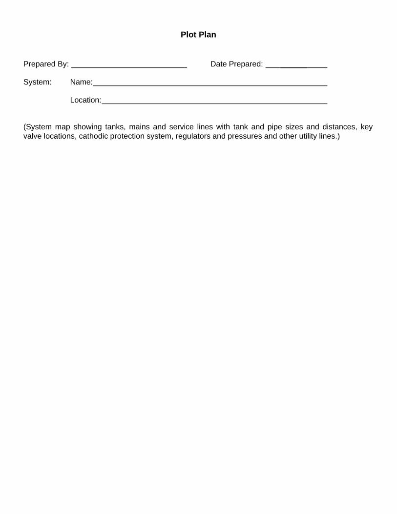
Plot Plan Prepared By: Date Prepared: ______ System: Name: Location: (System map showing tanks, mains and service lines with tank and pipe sizes and distances, key valve locations, cathodic protection system, regulators and pressures and other utility lines.)
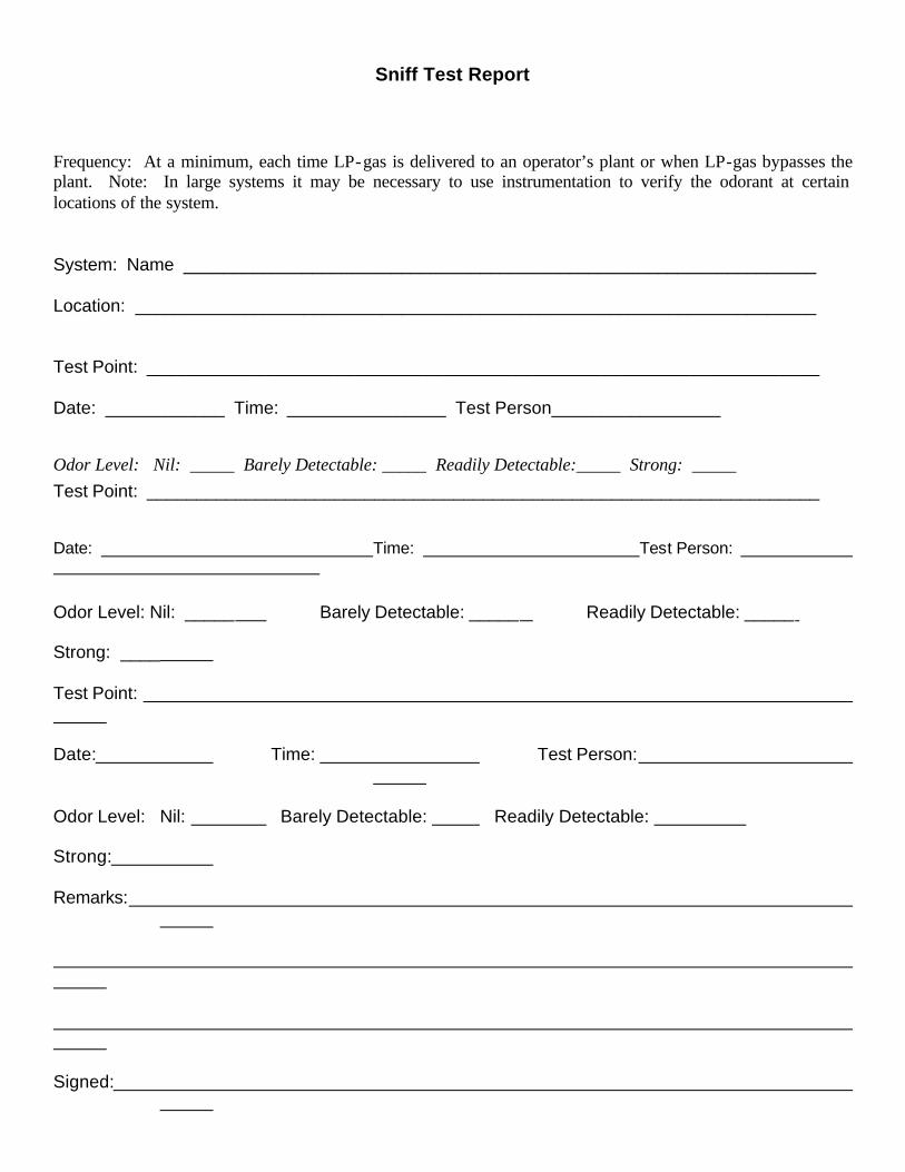
Sniff Test Report Frequency: At a minimum, each time LP-gas is delivered to an operator’s plant or when LP-gas bypasses the plant. Note: In large systems it may be necessary to use instrumentation to verify the odorant at certain locations of the system. System: Name ________________________________________________________________ Location: _____________________________________________________________________ Test Point: ____________________________________________________________________ Date: ____________ Time: ________________ Test Person_________________
Odor Level: Nil: _____ Barely Detectable: _____ Readily Detectable:_____ Strong: _____ Test Point: ____________________________________________________________________
Date: Time: Test Person:
Odor Level: Nil: _____ Barely Detectable: _____ Readily Detectable: _____ Strong: ____ Test Point: Date: Time: Test Person:
Odor Level: Nil: Barely Detectable: Readily Detectable: Strong: Remarks:
Signed:
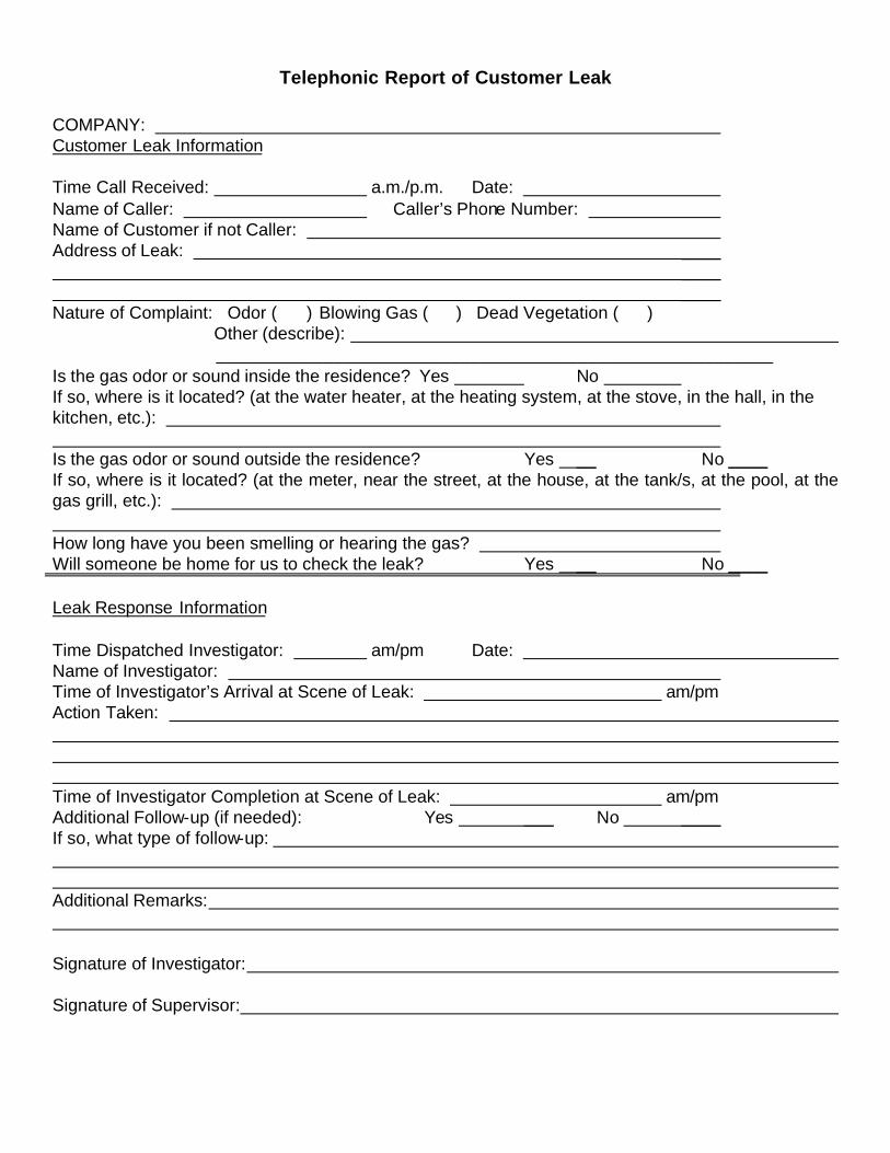
Telephonic Report of Customer Leak COMPANY: Customer Leak Information Time Call Received: a.m./p.m. Date: Name of Caller: Caller’s Phone Number: Name of Customer if not Caller: Address of Leak: ____ ____ ____ Nature of Complaint: Odor ( ) Blowing Gas ( ) Dead Vegetation ( ) Other (describe): _________________________________________________________ Is the gas odor or sound inside the residence? Yes No If so, where is it located? (at the water heater, at the heating system, at the stove, in the hall, in the kitchen, etc.): Is the gas odor or sound outside the residence? Yes __ No ____ If so, where is it located? (at the meter, near the street, at the house, at the tank/s, at the pool, at the gas grill, etc.): How long have you been smelling or hearing the gas? Will someone be home for us to check the leak? Yes __ No ____ Leak Response Information Time Dispatched Investigator: am/pm Date: Name of Investigator: Time of Investigator’s Arrival at Scene of Leak: am/pm Action Taken: Time of Investigator Completion at Scene of Leak: am/pm Additional Follow-up (if needed): Yes ___ No ____ If so, what type of follow-up: Additional Remarks: Signature of Investigator: Signature of Supervisor:
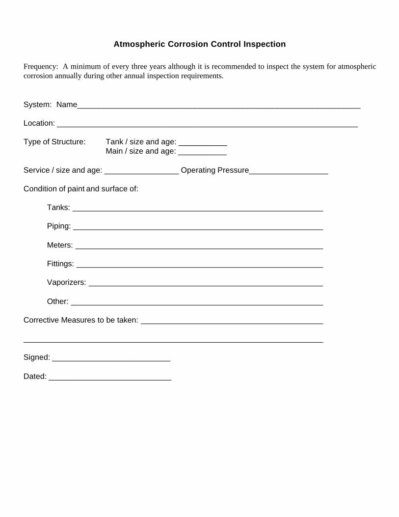
Atmospheric Corrosion Control Inspection Frequency: A minimum of every three years although it is recommended to inspect the system for atmospheric corrosion annually during other annual inspection requirements. System: Name_________________________________________________________________ Location: _____________________________________________________________________ Type of Structure: Tank / size and age: ___________ Main / size and age: ___________ Service / size and age: _________________ Operating Pressure__________________ Condition of paint and surface of: Tanks: Piping: Meters: Fittings: Vaporizers: Other: Corrective Measures to be taken: Signed: ___________________________ Dated: ____________________________
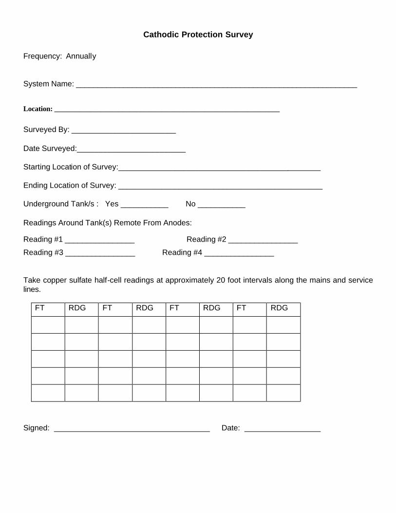
Cathodic Protection Survey Frequency: Annually System Name: _________________________________________________________________
Location: _______________________________________________________________
Surveyed By: ________________________ Date Surveyed:_________________________ Starting Location of Survey:_______________________________________ Ending Location of Survey: _______________________________________________ Underground Tank/s : Yes ___________ No ___________ Readings Around Tank(s) Remote From Anodes:
Reading #1 ________________ Reading #2 ________________
Reading #3 ________________ Reading #4 ________________
Take copper sulfate half-cell readings at approximately 20 foot intervals along the mains and service lines.
FT RDG FT RDG FT RDG FT RDG
Signed: Date:
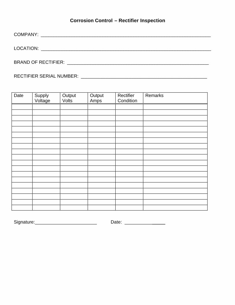
Corrosion Control – Rectifier Inspection COMPANY: __________________________________________________________________ LOCATION: __________________________________________________________________ BRAND OF RECTIFIER: _______________________________________________________ RECTIFIER SERIAL NUMBER: _________________________________________________ Date Supply
Voltage Output Volts
Output Amps
Rectifier Condition
Remarks
Signature: Date: _____
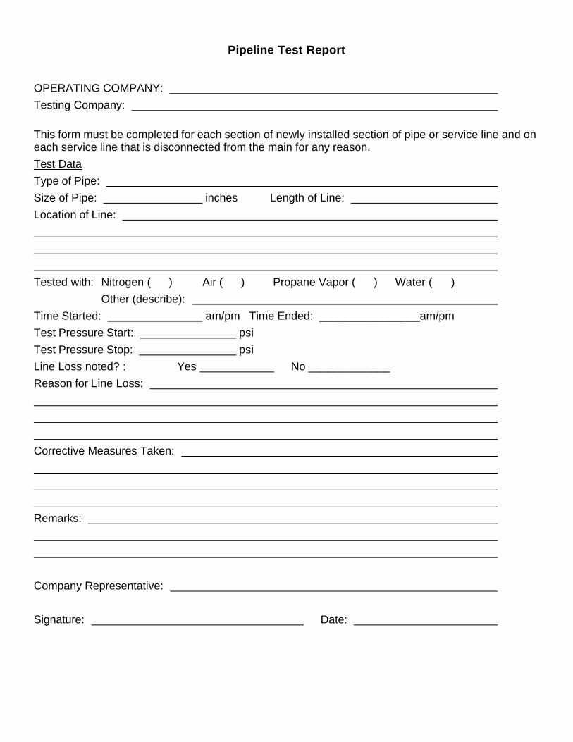
Pipeline Test Report
OPERATING COMPANY: Testing Company: This form must be completed for each section of newly installed section of pipe or service line and on each service line that is disconnected from the main for any reason. Test Data Type of Pipe: Size of Pipe: inches Length of Line: Location of Line: Tested with: Nitrogen ( ) Air ( ) Propane Vapor ( ) Water ( ) Other (describe): Time Started: am/pm Time Ended: ________________am/pm Test Pressure Start: psi Test Pressure Stop: psi Line Loss noted? : Yes No _____________ Reason for Line Loss: Corrective Measures Taken: Remarks: Company Representative: Signature: Date:
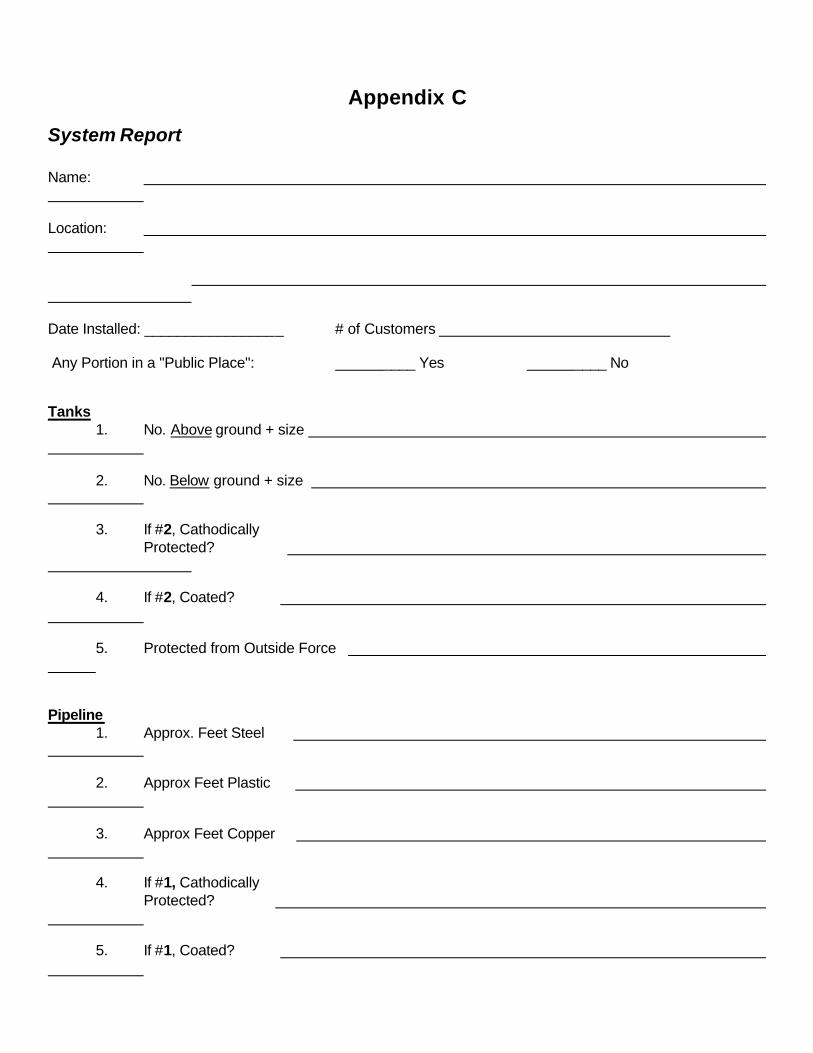
Appendix C
System Report Name: Location: Date Installed: _________________ # of Customers Any Portion in a "Public Place": ____ Yes ____ No Tanks 1. No. Above ground + size 2. No. Below ground + size 3. If #2, Cathodically Protected? 4. If #2, Coated? 5. Protected from Outside Force Pipeline 1. Approx. Feet Steel 2. Approx Feet Plastic 3. Approx Feet Copper 4. If #1, Cathodically Protected? 5. If #1, Coated?
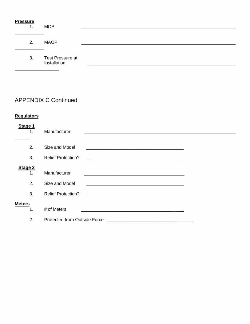
Pressure 1. MOP 2. MAOP 3. Test Pressure at Installation APPENDIX C Continued Regulators Stage 1 1. Manufacturer 2. Size and Model _______________________________________ 3. Relief Protection? _____________________________________ Stage 2 1. Manufacturer ________________________________________ 2. Size and Model _______________________________________ 3. Relief Protection? _____________________________________ Meters 1. # of Meters ____________________________________ ___ 2. Protected from Outside Force ____________________________ _
APPENDIX M – Manufacturers Instructions
<Insert copies of manufacturers instructions behind this page.>