Embed Size (px)
Citation preview

New Government Polytechnic,
Patna-13
Presentation on Plane Table Surveying
Plane table surveying
- Plane table is a graphical method of surveying inwhich the field work and the plotting is donesimultaneously.
- It is adopted in small mapping.
- It is also ideally suited to filling detail on a mapalready prepare and available on the drawingsheets.
- It can also be used to prepare a fresh map with the linear measurements being taken with a chain ortape.
A simple plane table is a drawing board providedwith a ball and socket arrangement for levelingthe table,with an arrangement to fix the table to a tripod.
Plane Table And Tripod
- a plane alidade consists of a metallic rule with afine beveled edge called the fiduucialedge.
- This edge used for drawing line.- For sighting-by placing the ruling edge along the
points orlines marked on thesheet.
- Two frameare attached vertically at its end.
- The eye vane-a small metal framewith a silt.- The object vane-a framewith a fine hair placed
vertically,for bisecting – the part directed towards the object.
- The center of the eye vane and hair of the objectvane provides the line of site.
Alidade
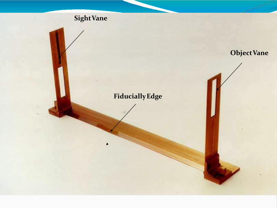
ObjectVane
SightVane
FiduciallyEdge

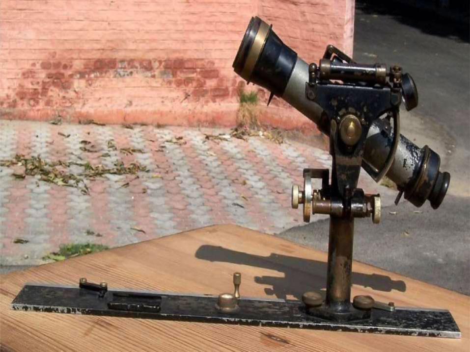
The alidade which is fitted with atelescope is known as a telescopicalidade.
It is used to take inclinedsights.
It increases the range and accuracy of thesights.
Itconsists of a small telescopewith a leveltube.
A graduated scale is mounted on thehorizontal axis.
One side of the metal ruler is used as theworking edge along which lines aredrawn.
The angles of elevation ordepression canbe read on the verticalcircle.
Telescopic Alidade
Spirit level can be used to level the planetable.
Itcan be tubular level which can be placed in two perpendicular positions and leveled.
Sprit level

A compass is used fororienting the plane table when it has to be used in more than one station.
When the table is shifted to another station ,the compass is placed along the meridian previously drawn and the table is rotated to make the needle read zero.
The table is then oriented to the same positionit occupied at the previousstation.
Trough compass
It requires the plane table to occupy a singlestation .
Orientation table is notrequired.
Toconduct the survey of an area ,the table iskept at a convenient station P commanding a full view of the area to besurveyed.
Radiation method
This method requiressetting the table upat minimum of two stations.
Orientation is essential and becan done by back sighting.
Two station A and B are selected so that they commanda full view of the area to besurveyed.
Intersection method

This method is used to connect the two or more stations , however it is similar to the compass traversing but are donesimultaneously.
Traversing is a method of surveying where by a series of lines aresurveyed.
Traverse may be open or closed one.
Traversing method
This is the method of orienting the table . a characteristic feature of resection is that the objective is to plot the station occupied by the table on the sheet rather than obtaining the other stations or plotting details.
Two method of orienting thetable
Method of back sighting
Method using troughcompass
Re-section method
It is suitable for location of details as well as contouringfor large scale maps directly in the field.
As surveying and plotting are done simultaneously in thefield, chances of getting omission of any detail get less.
The plotting details can immediately get compared with the actual objects present in the field. Thus errors aswell as accuracy of the plot can be ascertained as thework progresses in the field.
Contours and specific features can be representedand checked conveniently as the whole area is inview at the time of plotting.
Only relevant details are located because the map is drawnas thesurvey progresses. Irrelevant details get omitted in the fielditself.
The plane table survey is generally more rapid and lesscostly than most other types of survey.
As the instruments used are simple, not much skill for operation of instruments is required. This method ofsurvey requires no field book.
advantage

The plane table survey is not possible inunfavourable climates such as rain, fogetc.
This method of survey is not very accurateand thus unsuitable for large scale or precisework.
As no field book is maintained, plotting atdifferentscalerequire full exercise.
The method requires large amount of time to bespent in the field.
Quality of the final mapdepends largely on thedraftingcapability of thesurveyor.
This method is effective in relatively open countrywhere stations can be sighted easily.
disadvantage

Thank you
PRESENTATION ON ADVANCE SURVEYING
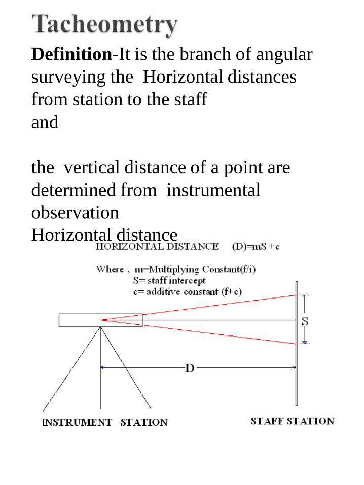
Definition-It is the branch of angular
surveying the Horizontal distances
from station to the staff
and
the vertical distance of a point are
determined from instrumental
observation
Horizontal distance
• When obstacles like river,
broken ground,streches of
water, tacheometry gives speed
& accuracy to work.
• In rough country where
measurement of horizontal &
vertical distances are difficult,
inaccurate & slow.
• In locating contours & filling
details in a topographic survey,
this method is fast & best.
• Tacheometer is used where chaining is
difficult such as river, vally, broken
boundries, stiff slope, undulations.
• It is used in the preparation of contour
maps, in which horizontal & vertical
distances are required to be measured.
• It is used for the survey road, railway.
• It is also used for the hydrographic survey.
• It is used for checking distances measured
by tape, chain & dumpy level.
• It is used where accuracy is not required.
• It saves time & money.

• Preparation of contour maps orplans.
• Used in hydrographic survey.
• Location survey for roads,railways, reservoir etc.
• For checking of more precisemeasurements.

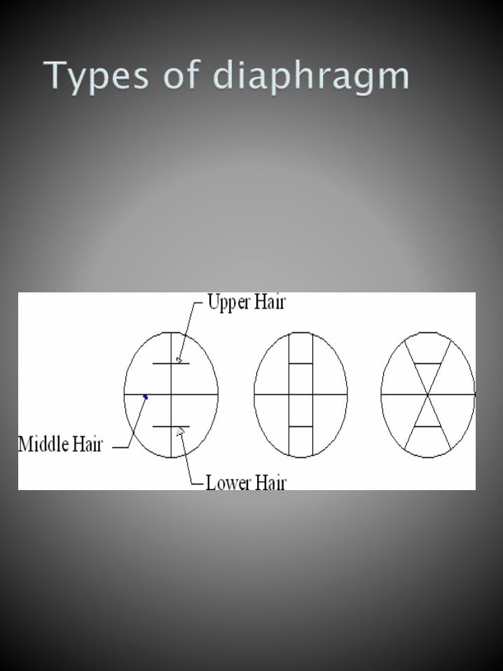
I)Tacheometer –It is a transit theodoliteprovided
with a stadia diaphragm.
• The diaphragm is provided with two horizontal stadia hairs in addition to regular cross hair.
• Additional hair should be equidistant from central one.
• Types of diaphragm commonly used
as follows.
• External focusing
• Internal focusing
• External focusing fitted with
anallatic lens.
Anallatic lens -It is an additional lens
generally provided in the external
focusing tacheometer between object
glass & eyepiece
Advantages of anallatic lens.
1) For calculation of horizontal &
vertical distances constant (f+c)=0,
if tacheometer is provided with
anallatic lens.
2) Calculation becomes simple.
• The value of constant (f/i)=100.
• The telescope should be
provided with anallatic lens.
• The telescope should be powerful,
magnification should be 20 to 30
times the diameter.
• The vision through the telescope
should be clear & bright image at
longer distance.
• In this method, the distance between two stadia hair is fixed.
• The reading corresponding to three cross hair is taken and difference between top and bottom hair is found out known as staff intercept.
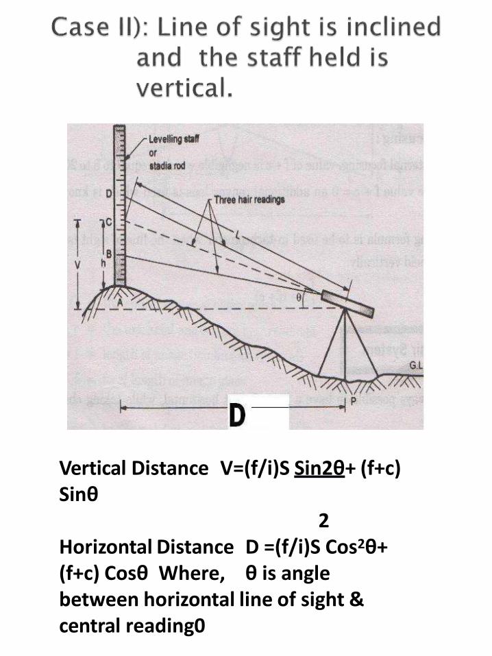
Vertical Distance V=(f/i)S Sin2θ+ (f+c)Sinθ
2Horizontal Distance D =(f/i)S Cos2θ+ (f+c) Cosθ Where, θ is angle between horizontal line of sight & central reading0

THANK YOU

PRESENTATION ON ADVANCE SURVEYING
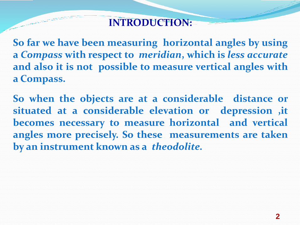
INTRODUCTION:
So far we have been measuring horizontal angles by usinga Compass with respect to meridian, which is less accurateand also it is not possible to measure vertical angles witha Compass.
So when the objects are at a considerable distance orsituated at a considerable elevation or depression ,itbecomes necessary to measure horizontal and verticalangles more precisely. So these measurements are takenby an instrument known as a theodolite.
2
THEODOLITE SURVEYING
The system of surveying in which the angles are
measured with the help of a theodolite, is called
Theodolite surveying.
3

CLASSIFICATION OF THEODOLITES
8
Theodolites may be classified as ;
A.BASE ON HORIZONTALAXIS
i) Transit Theodolite.
ii) Non Transit Theodolite.
B.BASE ON ANGEL
i) Vernier Theodolites.
ii)Micrometer Theodolites. iii)Electronic digital
theodolite.

CLASSIFICATION OF THEODOLITES
9
A. Transit Theodolite: A theodolite is called a transit theodolite
when its telescope can be transited i.e revolved through a
complete revolution about its horizontal axis in the vertical
plane, whereas in a-Non-Transit type, the telescope cannot be
transited. They are inferior in utility and have now become
obsolete.
CLASSIFICATION OF THEODOLITES
10
B.(a)Vernier Theodolite: For reading the graduated circle if
verniers are used ,the theodolite is called as a Vernier
Theodolite
(b) Whereas, if a micrometer is provided to read the graduated
circle the same is called as a Micrometer Theodolite.
( c )reading directly providing as digital num. if electronic
distance measuring is attached with it then it’s call total
station
Vernier type theodolites are commonly used .
11
A theodolite is designated by diameter of the
graduated circle on the lower plate.
The common sizes are 8cm to 12 cm while 14 cm to 25 cm
instrument are used for triangulation work.
Greater accuracy is achieved with larger theodolites
as they have bigger graduated circle with larger divisions hence
used where the survey works require high degree of accuracy.
USES OF THEODOLITE
The Theodolite is a most accurate surveying instrument mainly used for :
4
• Measuring horizontal and vertical angles.
• Locating points on a line.
• Prolonging survey lines.
• Finding difference of level.
• Setting out grades
• Ranging curves
• Tacheometric Survey
TRANSIT VERNIER THEODOLITE
A Transit vernier theodolite essentially consist of the
following :
6. T- Frame.
7. Plumb –bob.
8. Tripod Stand.
1. Levelling Head.
2. Lower Circular Plate.
3. Upper Plate.
4. Telescope.
5. Vernier Scale.
12
TERMS USED IN MANIPULATING A TRANSIT VERNIER
THEODOLITE.
1. Centering : Centering means setting the theodolite exactly
over an instrument- station so that its vertical axis lies
immediately above the station- mark. It can be done by
means of plumb bob suspended from a small hook attached
to the vertical axis of the theodolite.
The centre shifting
arrangement if provided with the instrument helps in easy
and rapid performance of the centring.
13
TERMS USED IN MANIPULATING A TRANSIT VERNIER THEODOLITE.
2. Transiting :
Transiting is also known as plunging or reversing. Itis the process of turning the telescope about its horizontalaxis through 1800 in the vertical plane thus bringing itupside down and making it point , exactly in oppositedirection.
TERMS USED IN MANIPULATING A TRANSIT VERNIER THEODOLITE.
3. Swinging the telescope
It means turning the telescope about its
vertical axis in the horizontal plane.
A swing is called right or left according as the telescope is
rotated clockwise or counter clockwise.

TERMS USED IN MANIPULATING A TRANSIT VERNIERTHEODOLITE.
4. Face Left
If the vertical circle of the instrument is on the leftside of the observer while taking a reading ,the positionis called the face left and
the observation taken on the horizontal or verticalcircle in this position, is known as the face leftobservation
16

TERMS USED IN MANIPULATING A TRANSIT VERNIER
THEODOLITE.
5. Face Right
If the vertical circle of the instrument is onthe right side of the observer while taking areading ,the position is called the face right and
the observation taken on the horizontal orvertical circle in this position, is known as the faceright observation.
17
TERMS USED IN MANIPULATING A TRANSIT
VERNIER THEODOLITE.
6. Changing Face
It is the operation of bringing the vertical circle to
the right of the observer ,if originally it is to the left ,
and vice – versa.
It is done in two steps; Firstly revolve the
telescope through 1800 in a vertical plane and then
rotate it through 1800 in the horizontal plane i.e first
transit the telescope and then swing it through 1800.
18
TERMS USED IN MANIPULATING A TRANSIT VERNIERTHEODOLITE.
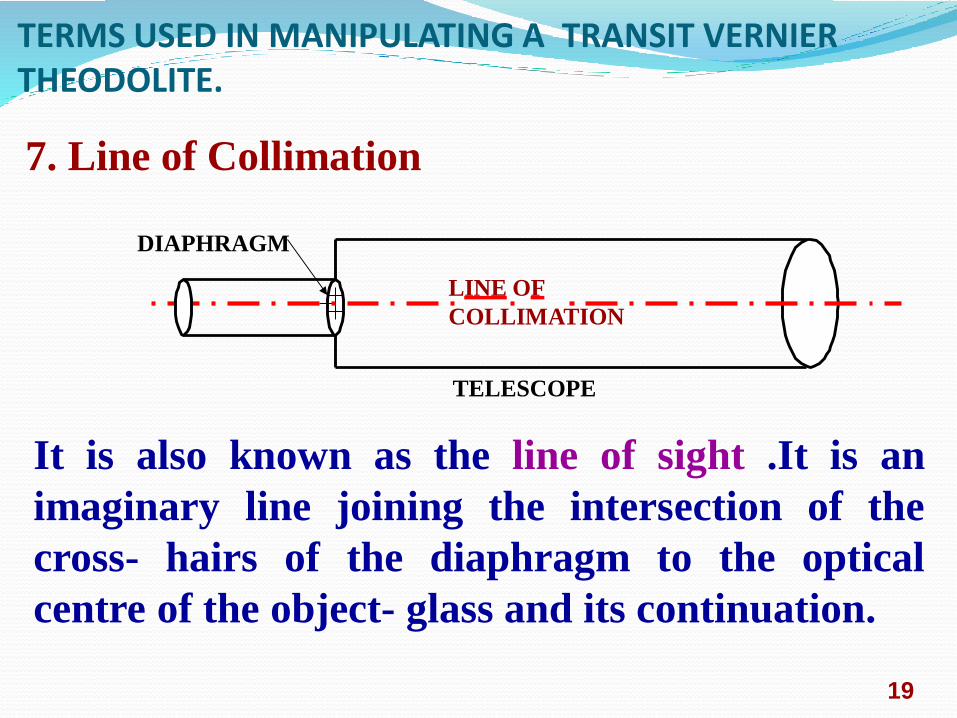
DIAPHRAGM
LINE OF
COLLIMATION
TELESCOPE
19
It is also known as the line of sight .It is an
imaginary line joining the intersection of the
cross- hairs of the diaphragm to the optical
centre of the object- glass and its continuation.
7. Line of Collimation

TERMS USED IN MANIPULATING A TRANSIT VERNIER THEODOLITE.
8. Axis of the telescope
OBJECT GLASS
AXIS OF THE TELESCOPE
.
TELESCOPE
It is also known an imaginary line joining the
optical centre of the object- glass to the centre of
eye piece.
20
9. Axis of the Level Tube
It is also called the bubble line.
It is a straight line tangential to the longitudinal
curve of the level tube at the centre of the tube.
It is horizontal when the bubble is in the centre.
21
TERMS USED IN MANIPULATING A TRANSIT VERNIER THEODOLITE.
10. Vertical Axis
It is the axis about which the telescope can be
rotated in the horizontal plane.
11. Horizontal Axis
It is the axis about which the telescope can be
rotated in the vertical plane.
It is also called the trunion axis.
22

Thank you
New Government Polytechnic,Patna-13
PPT On Simple Circular Curves
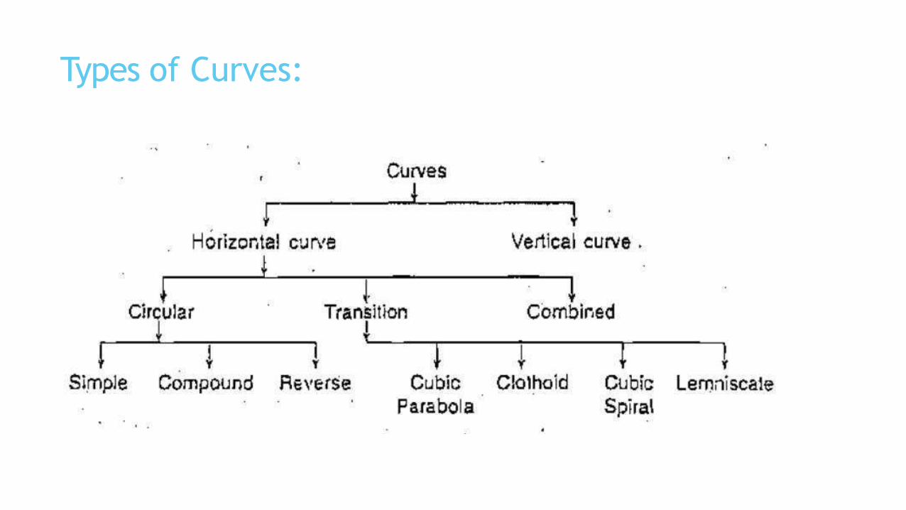
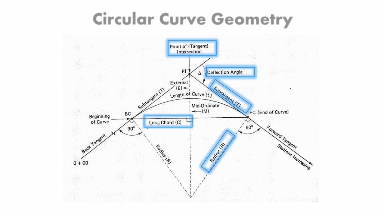
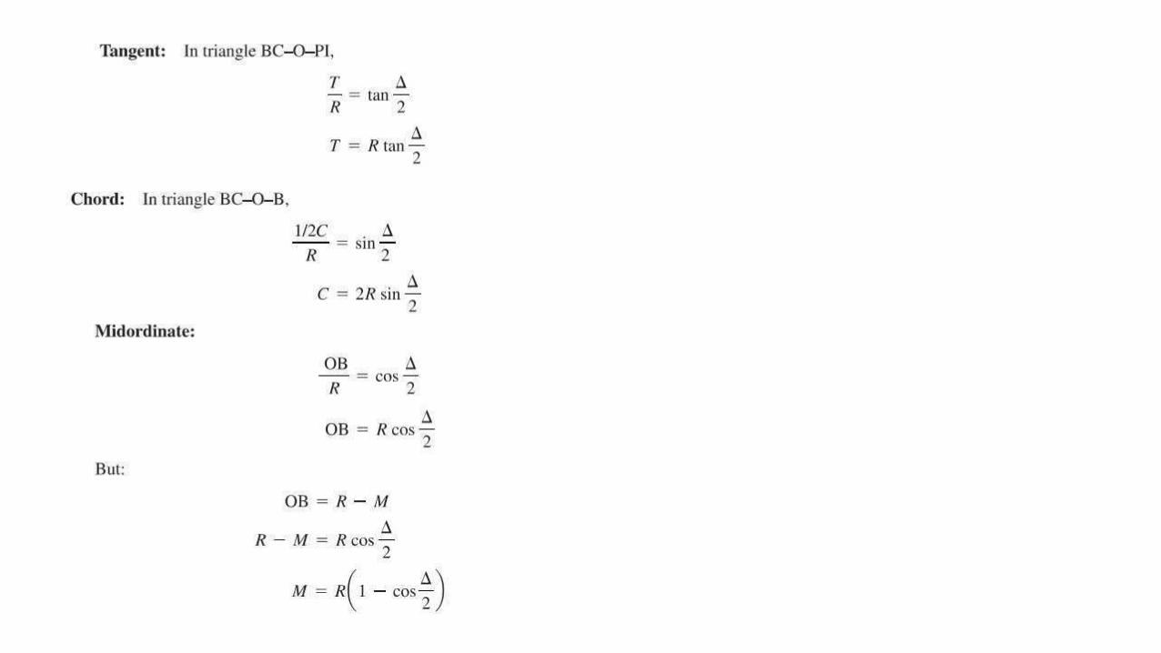
Types of Curves:

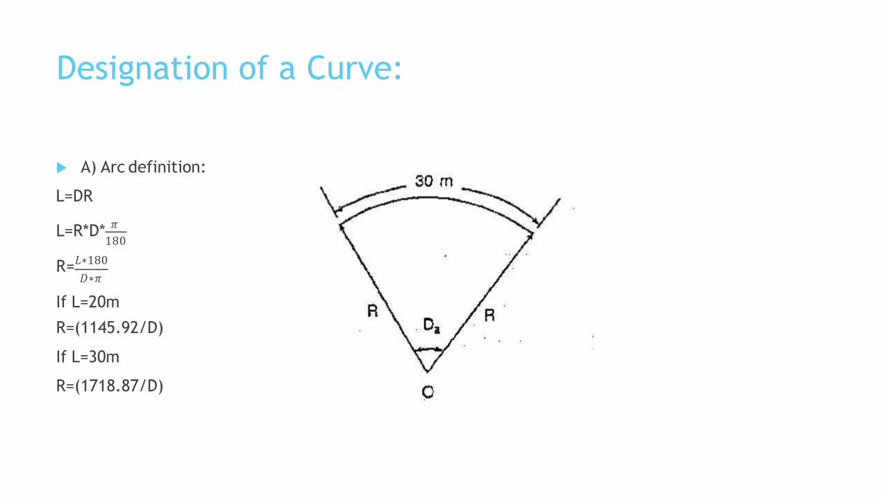
Designation of a Curve:
A) Arc definition:
L=DR
L=R*D*𝜋
180
R=𝐿∗180
𝐷∗𝜋
If L=20m
R=(1145.92/D)
If L=30m
R=(1718.87/D)
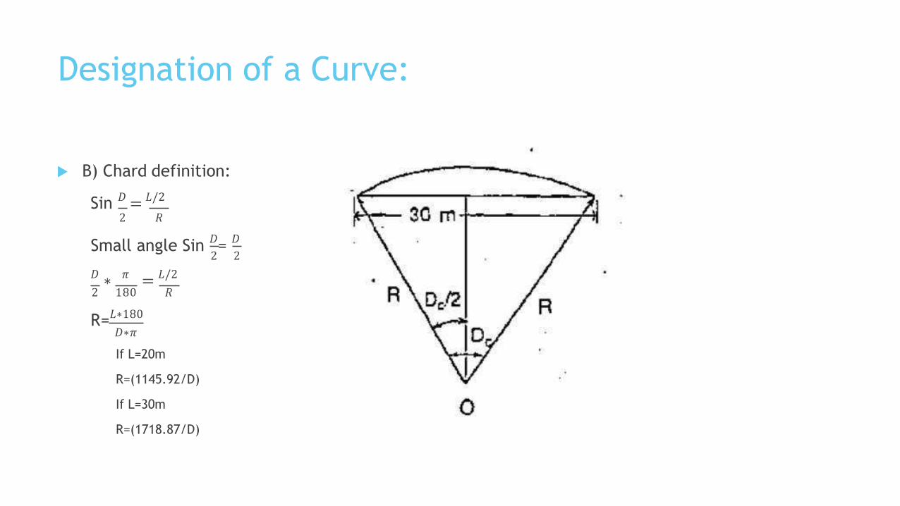
Designation of a Curve:
B) Chard definition:
Sin 𝐷 = 𝐿/2
2 𝑅
Small angle Sin 𝐷=𝐷
2 2
𝐷 ∗ 𝜋 = 𝐿/2
2 180 𝑅
R=𝐿∗180
𝐷∗𝜋
If L=20m
R=(1145.92/D)
If L=30m
R=(1718.87/D)


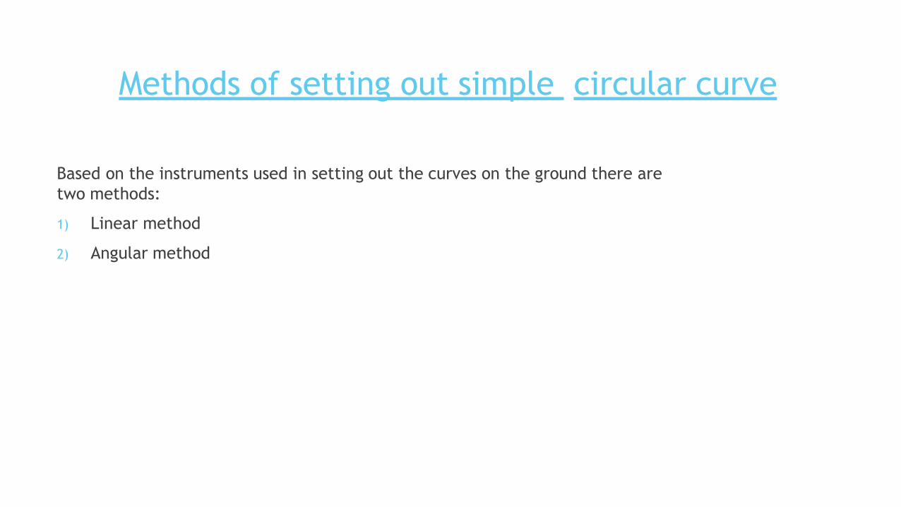
Based on the instruments used in setting out the curves on the ground there are
two methods:
1) Linear method
2) Angular method
Methods of setting out simple circular curve
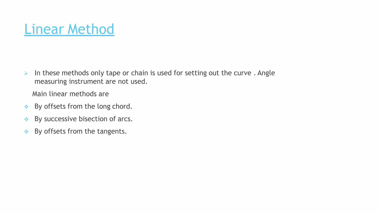
Linear Method
In these methods only tape or chain is used for setting out the curve . Angle
measuring instrument are not used.
Main linear methods are
By offsets from the long chord.
By successive bisection of arcs.
By offsets from the tangents.
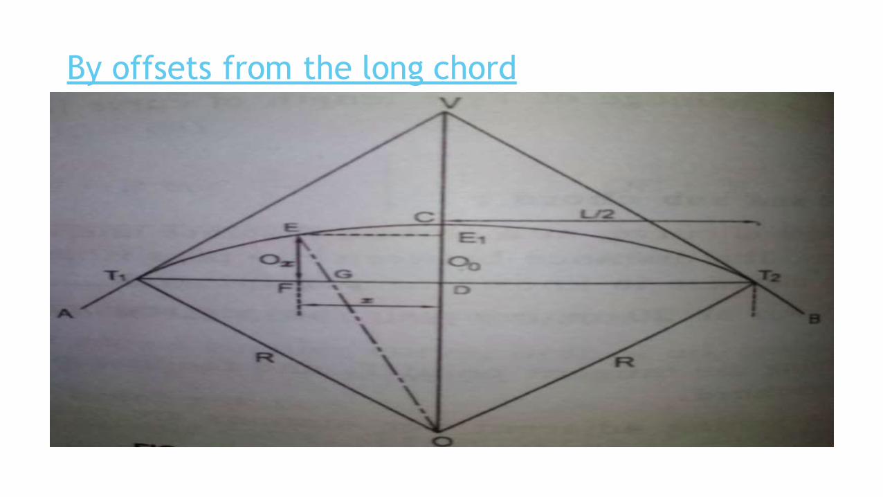
By offsets from the long chord
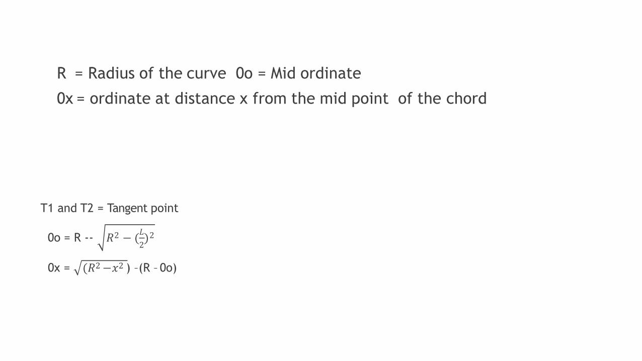
R = Radius of the curve 0o = Mid ordinate
0x = ordinate at distance x from the mid point of the chord
T1 and T2 = Tangent point
𝐿
20o = R -- 𝑅 − ( )2 2
0x = (𝑅2 −𝑥2 ) –(R – 0o)
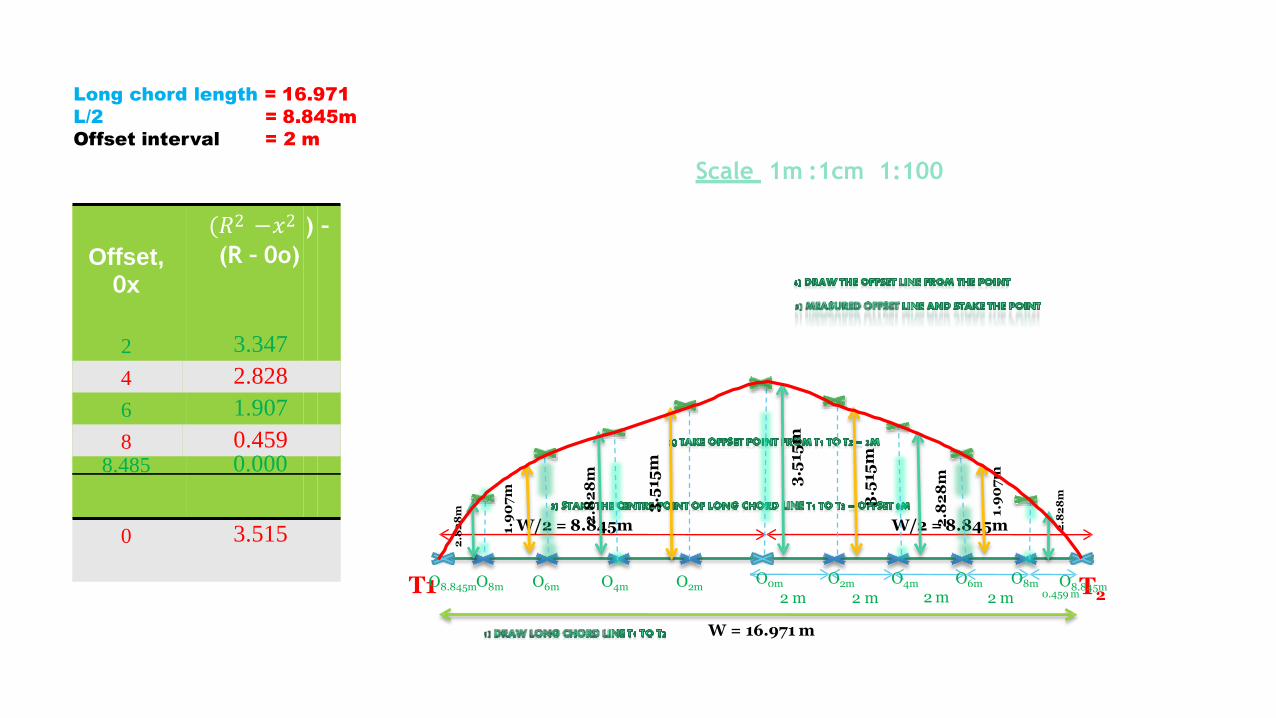
Offset,0x
(𝑅2 −𝑥2
(R – 0o)
) –
0 3.515
2 3.347
4 2.828
6 1.907
8 0.4598.485 0.000
Long chord length = 16.971
L/2
Offset interval
= 8.845m
= 2 m
Scale 1m :1cm 1:100
T2
W/2 = 8.845m W/2 = 8.845m
2m 0.459m
O0m2 m
W = 16.971 m
O2m O4m2 m
O6m O8m2 m
O8.845mO2mT1O8.845mO8m O6m O4m
3.5
15m
3.5
15m
2.8
28
m
1.9
07
m
2.8
28
m
3.5
15m
2.8
28
m
1.9
07
m
2.8
28
m

By successive bisection of arcs
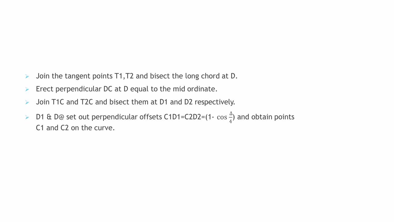
Join the tangent points T1,T2 and bisect the long chord at D.
Erect perpendicular DC at D equal to the mid ordinate.
Join T1C and T2C and bisect them at D1 and D2 respectively.
∆
4 D1 & D@ set out perpendicular offsets C1D1=C2D2=(1- cos ) and obtain points
C1 and C2 on the curve.
By offsets from the tangents
The offsets from the tangents can be of two types
1) Radial offsets
2) Perpendicular offsets
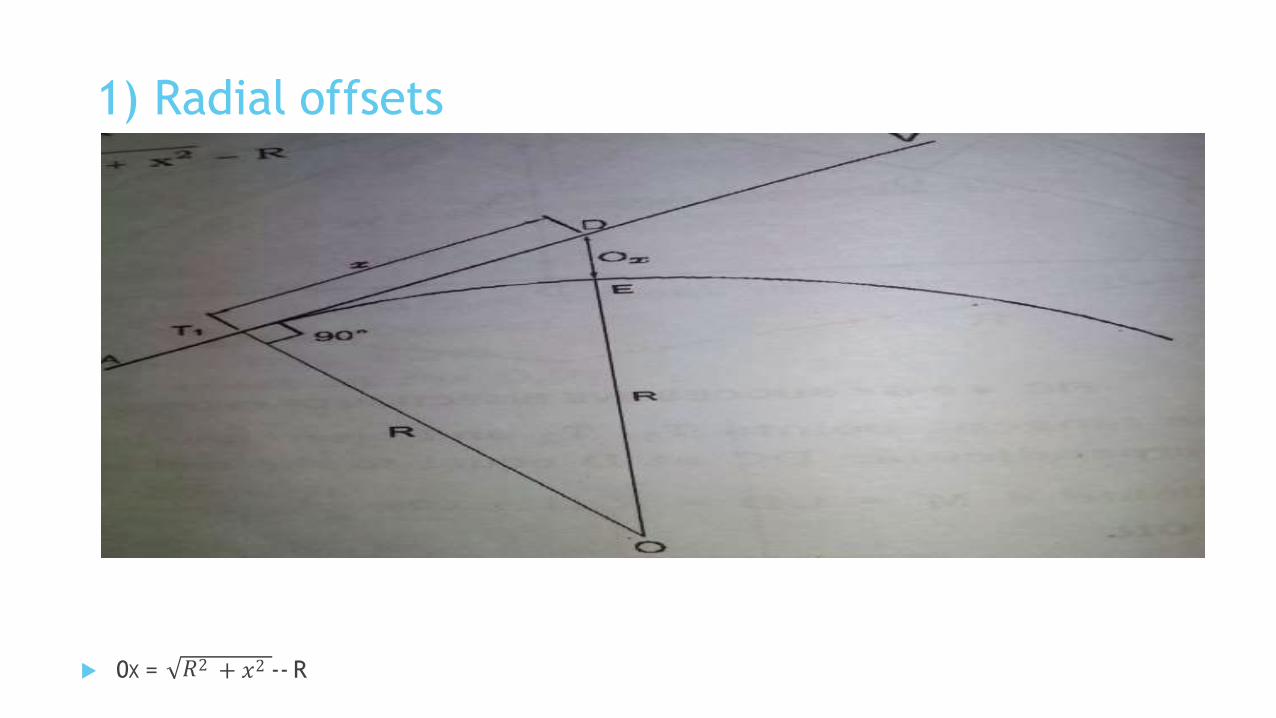
1) Radial offsets
0X = 𝑅2 + 𝑥2 -- R
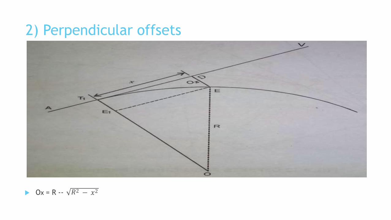
2) Perpendicular offsets
Ox = R -- 𝑅2 − 𝑥2
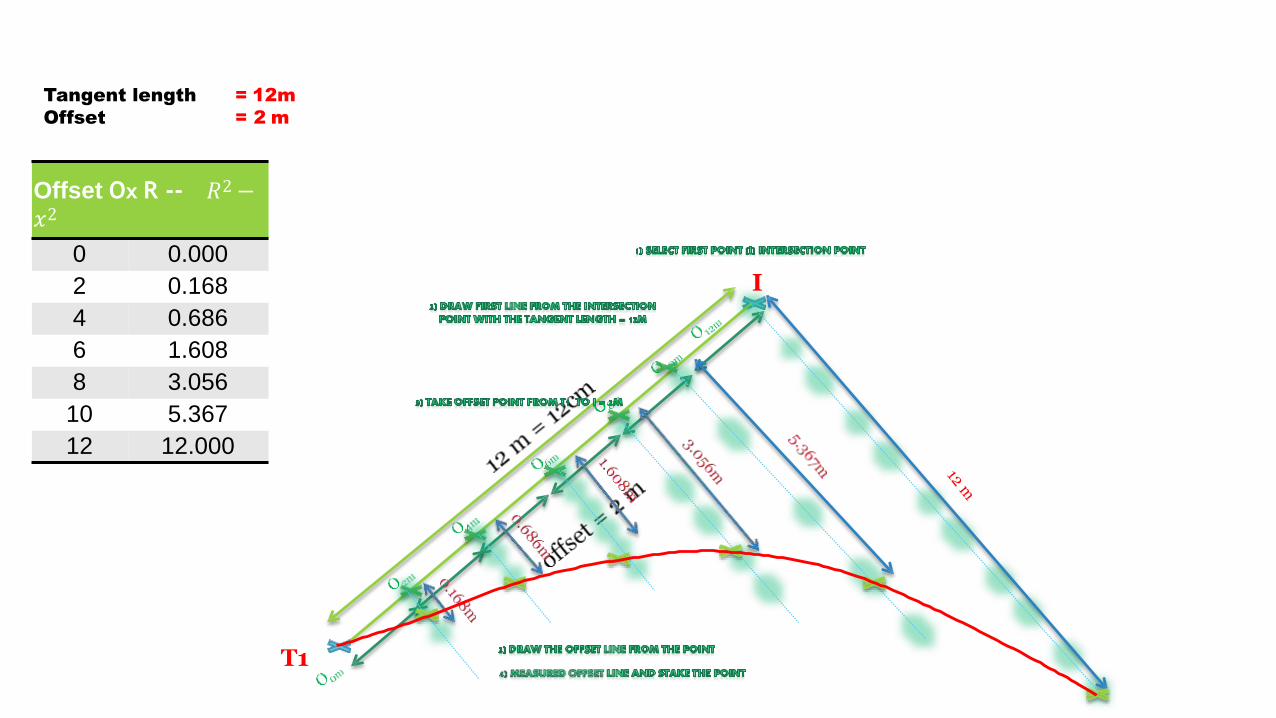
Offset Ox R -- 𝑅2 −𝑥2
0 0.000
2 0.168
4 0.686
6 1.608
8 3.056
10 5.367
12 12.000
Tangent length = 12m
Offset = 2 m
I
T1
Angular Method
This methods are used when the length of curve is large.
The Angular methods are:
1) Rankine method of tangential angles
2) Two theodolite method
3) Tacheometric method
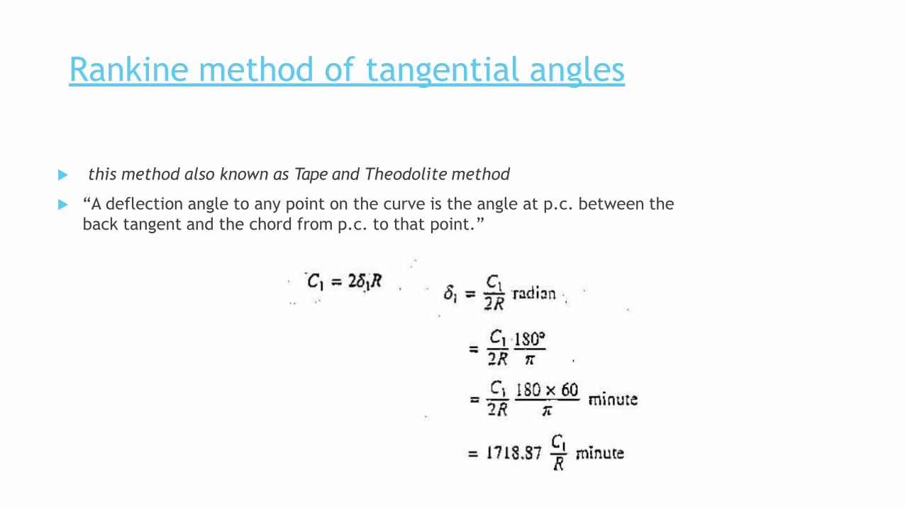
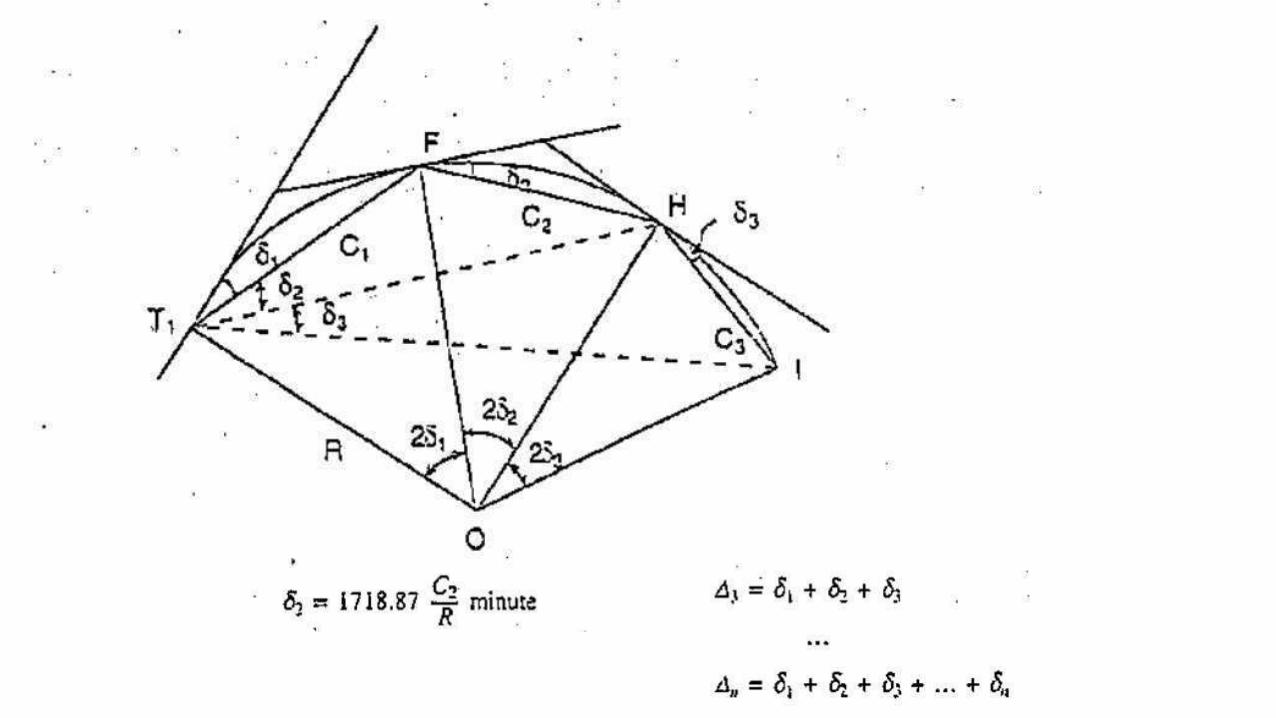
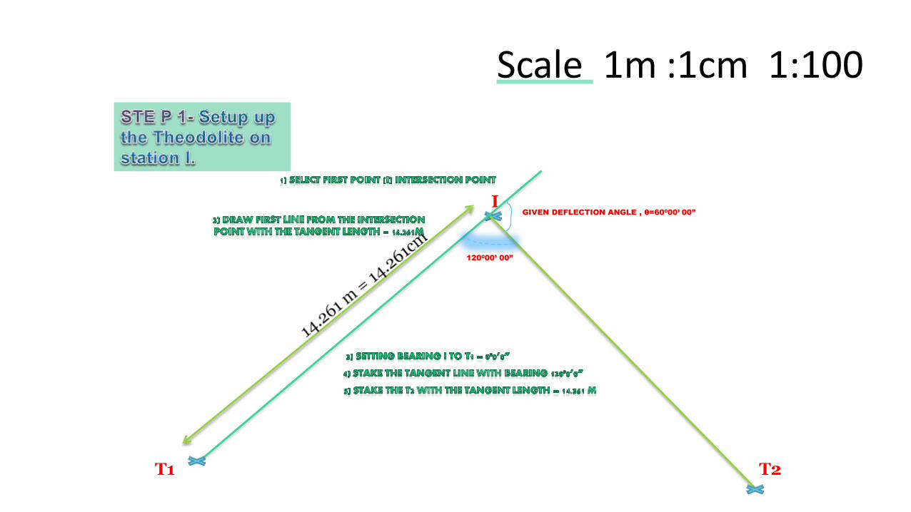
Rankine method of tangential angles
this method also known as Tape and Theodolite method
“A deflection angle to any point on the curve is the angle at p.c. between the
back tangent and the chord from p.c. to that point.”

Radius, R 24.7m
Deflection angle , 600
Offset 5m
Chainage intersection point, I 20 m
Tangent length
Chainage T1
Arc length
Chainage T2
= 14.261m
= 5.739m
= 25.866m
= 31.605m
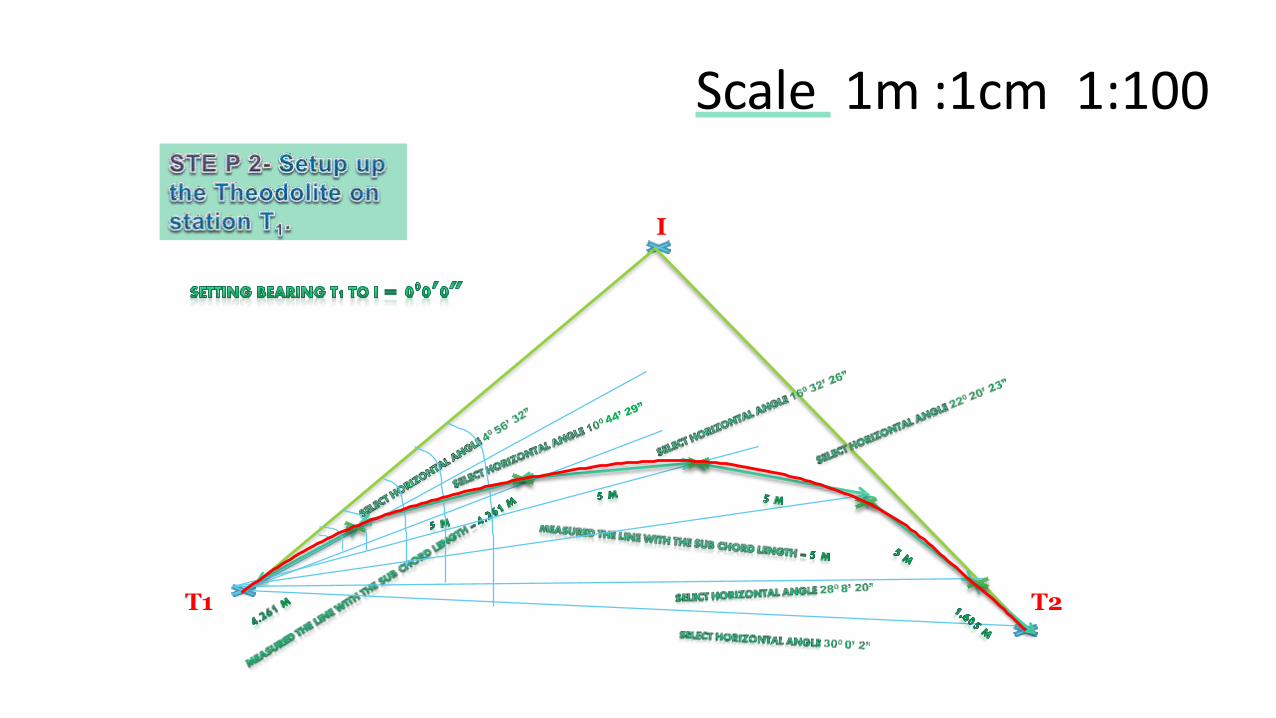
Stn. Chainage Chord length, C Deflection angle, Setting out angle,
T1 5.739 0 00 0’ 0” 00 0’ 0”
1 10 4.261 40 56’ 32” 40 56’ 32”
2 15 5.000 50 47’ 57” 100 44’ 29”
3 20 5.000 50 47’ 57” 160 32’ 26”
4 25 5.000 50 47’ 57” 220 20’ 23”
5 30 5.000 50 47’ 57” 280 8’ 20”
T2 31.605 1.605 10 51’ 42” 300 0’ 2”
= 25.866 = 300 00’ 2” θ / 2 = 600 / 2 = 300
I
T1
Scale 1m :1cm 1:100
T2
120000’ 00”
GIVEN DEFLECTION ANGLE , θ=60000’ 00”
I
T1
Scale 1m :1cm 1:100
T2
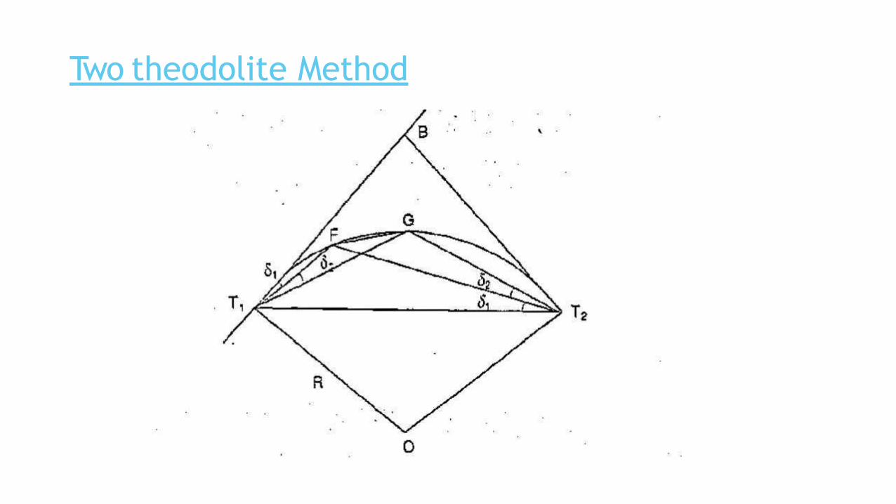
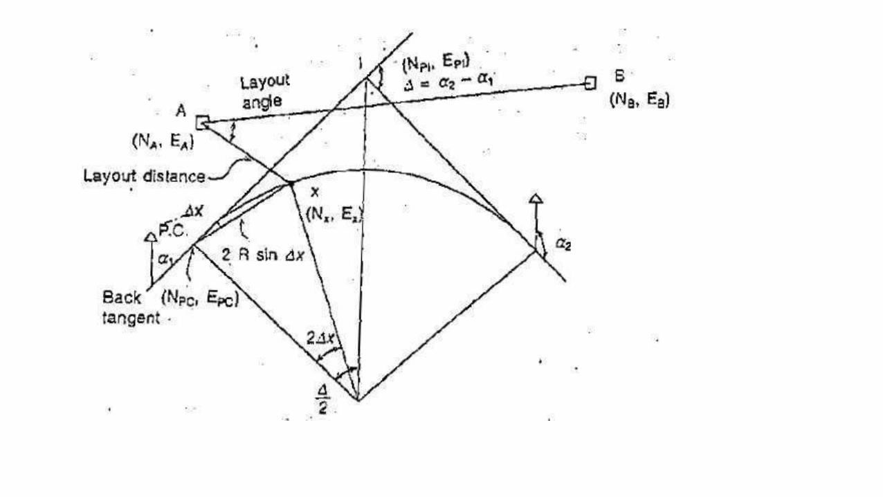
Two theodolite Method

Thank You

PPT On Advance SurveyingEquipments
New Government Polytechnic, Patna-13
Modern equipments
• EDM – Electronic distance measurement eqp.
• Auto level.
• Digital level.
• Total station.
• GPS – global positioning system.
EDM
• Now separate EDM are not very popular , instead Total Station
which have in built EDM is being used .
• Measurement of distance is accomplished with a modulatedmicrowave or infrared carrier signal, generated by a small solid-state emitter within the instrument's optical path, and bouncedoff of the object to be measured. The modulation pattern in thereturning signal is read and interpreted by the onboard computerin the EDM. The distance is determined by emitting and receivingmultiple frequencies, and determining the integer number ofwavelengths to the target for each frequency.

Hand held EDM
• Very handy,
• Cheap,
• Can be used with accuracy of 10mm or so,
• Useful for remote measurements like contact wire etc.,
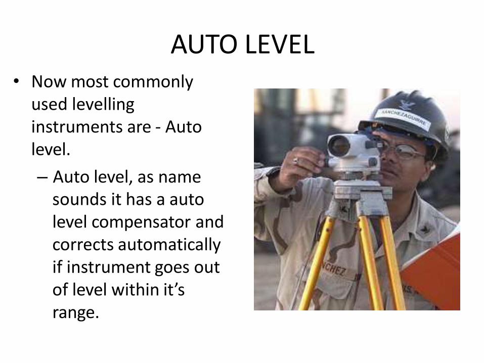
AUTO LEVEL• Now most commonly
used levelling instruments are - Auto level.
– Auto level, as name sounds it has a auto level compensator and corrects automatically if instrument goes out of level within it’s range.
• With auto level:-
–Survey work can be done fast,
–Less chances of error,
–Magnification available is more,
–Range is more,
–Image is erect so less chances of error.

Digital level• They are not popular instead
auto levels are more extensively used.
• The Trimble DiNi Digital Level : Determine accurate height information 60% faster than with automatic leveling
• Eliminate errors and reduce rework with digital readings
• Transfer data to the office easily
• Measure to a field of just 30 cm
COMPONENTS OF DIGITAL LEVEL
• The following discussion on digital levels has been
primarily taken from Schoffield (2002).
• Main components of digital level consist of two parts:
Hardware (Digital level and levelling staff) and
Software.
• Both digital level and associated staff are
manufactured so that they can be used for both
conventional and digital operations.
• Typically digital level has the same optical and
mechanical components as a normal automatic level.
• However, for the purpose of electronic staff reading a
beam splitter is incorporated which transfers the bar
code image to a detector diode array.
• The light, reflected from the white elements only of
the bar code, is divided into infrared and visible light
components by the beam splitter.

• The visible light passes on to the observer, the
infrared to diode array.
• The acquired bar code image is converted into an
analogous video signal, which is then compared with
a stored reference code within the instrument.

• Various capabilities of digital levels are as follows:
1. measuring elevation.
2. measuring height difference.
3.measuring height difference with multiple
instrument positions.
4. levelling
6. setting out with horizontal distance
7. levelling of ceilings


PRINCIPLE OF EDMI• The general principle involves sending a modulated
Electro-magnetic (EM) beam from one transmitter at
the master station to a reflector at the remote station
and receiving it back at the master station.
• The instrument measures slope distance between
transmitter and receiver by modulating the continuous
carrier wave at different frequencies, and then
measuring the phase difference at the master station
between the outgoing and the incoming signals. This
establishes the following relationship for a double
distance (2D):

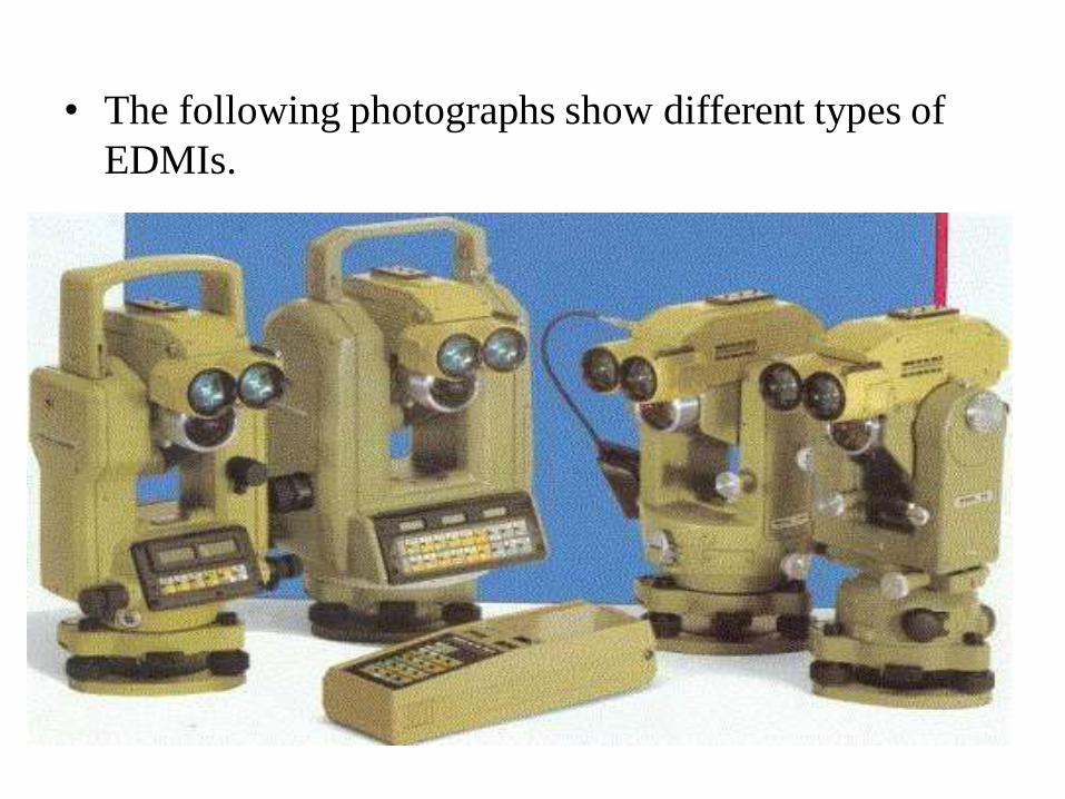
• The following photographs show different types of
EDMIs.

OPERATION WITH EDMI
• Measurement with EDMI involves four basic steps:
(a) Set up
(b) Aim
(c) Measure
(d) Record
• Setting up: The instrument is centered over a station
by means of tribrach. Reflector prisms are set over
the remote station on tribrach.
• Aiming: The instrument is aimed at prisms by using
sighting devices or theodolite telescope. Slow motion
screws are used to intersect the prism centre. Some kind
of electronic sound or beeping signal helps the user to
indicate the status of centering.
• Measurement: The operator presses the measure button
to record the slope distance which is displayed on LCD
panel.
• Recording: The information on LCD panel can be
recorded manually or automatically. All meteorological
parameters are also recorded.

ERROR IN MEASUREMENT WITH EDMI
1. Instrument errors :
• centering at the master and slave station.
• pointing/sighting of reflector.
• entry of correct values of prevailing atmospheric
conditions.

2. Atmospheric errors :
Meteorological conditions (temperature, pressure,
humidity, etc.) have to be taken into account to
correct for the systematic error arising due to this.
These errors can be removed by applying an
appropriate atmospheric correction model that takes
care of different meteorological parameters from the
standard one.
3. Instrumental error :
Consists of three components - scale error, zero error
and cyclic error. These are systematic in nature

TOTAL STATION
• Basic Principle
A total station integrates the functions of a theodolite for measuring angles, an EDM for measuring distances, digital data and a data recorder. Examples of total stations are the Sokkia Set4C and the Geodimeter 400 series. All total stations have similar constructional features regardless of their age or level of technology, and all perform basically the same functions.
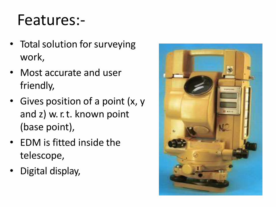
Features:-
• Total solution for surveying work,
• Most accurate and user friendly,
• Gives position of a point (x, y and z) w. r. t. known point (base point),
• EDM is fitted inside the telescope,
• Digital display,

• On board memory to store data,
• Compatibility with computers,
• Measures distance and angles and displays coordinates,
• Auto level compensator is available,
• Can work in lesser visibility also,
• Can measure distances even without prismatic target for
lesser distances,
• Is water proof,
• On board software are available,
• Can be used for curve layout after feeding data.
USES:-
Total Stations can be used for:
• General purpose angle measurement
• General purpose distance measurement
• Provision of control surveys
• Contour and detail mapping
• Setting out and construction work

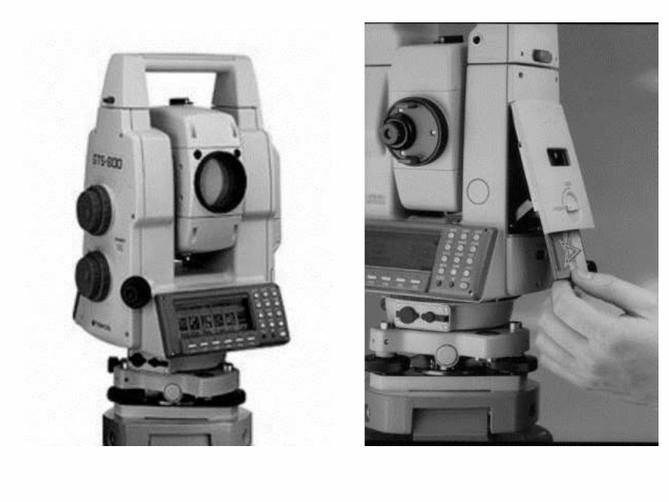
STORAGE• Most TS have on-board storage of records using
PCMCIA memory cards of different capacity. The
card memory unit can be connected to any external
computer or to a special card reader for data transfer.
• The observations can also be downloaded directly
into intelligent electronic data loggers. Both systems
can be used in reverse to load information into the
instruments.
• Some instruments and/or data loggers can be
interfaced directly with a computer for immediate
processing and plotting of the data (Kavanagh, 2003).
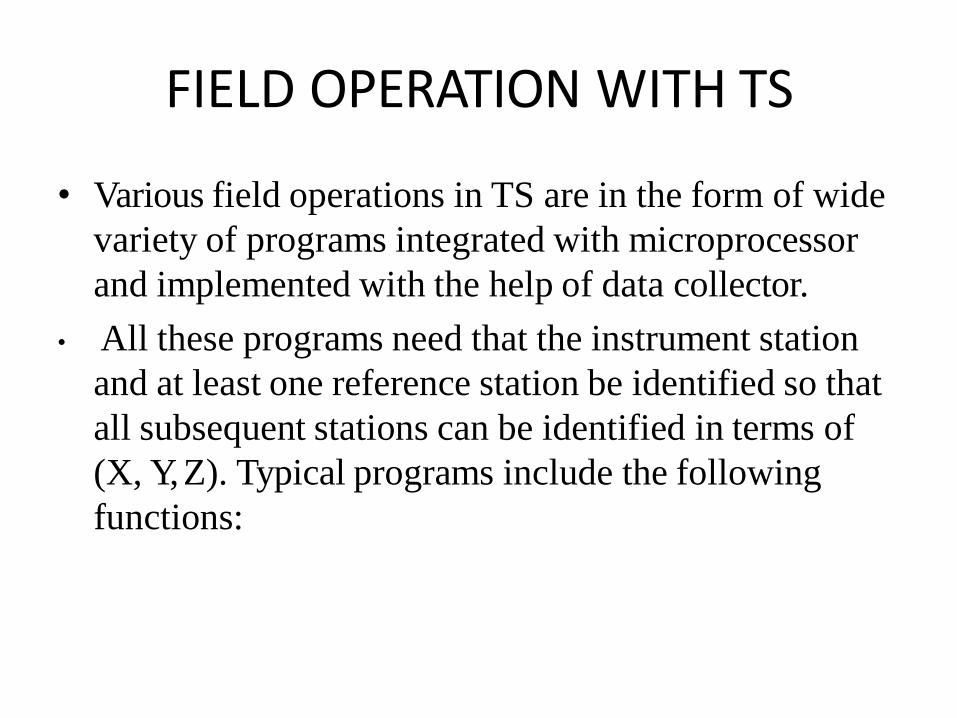
FIELD OPERATION WITH TS
• Various field operations in TS are in the form of wide
variety of programs integrated with microprocessor
and implemented with the help of data collector.
• All these programs need that the instrument station
and at least one reference station be identified so that
all subsequent stations can be identified in terms of
(X, Y, Z). Typical programs include the following
functions:

• Point location
• Missing line measurement (MLM)
• Resection
• Remote distance and elevation measurement
• Offset measurements
• Layout or setting out operation
• Area computation
• For details on above functions, one can refer to the
user manual of any TS.
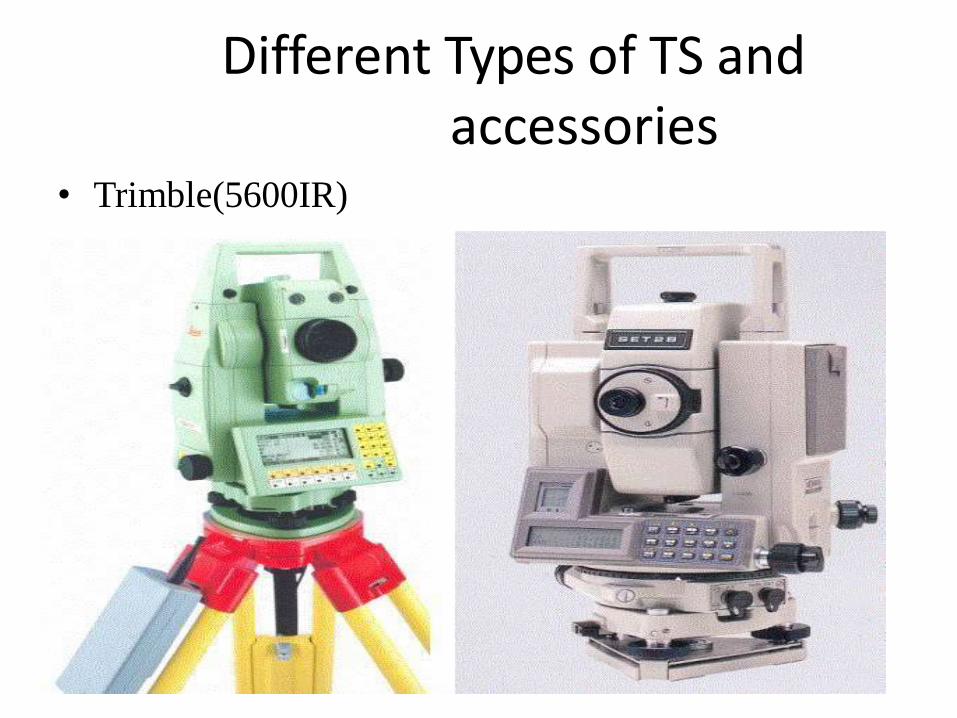
Different Types of TS and accessories
• Trimble(5600IR)
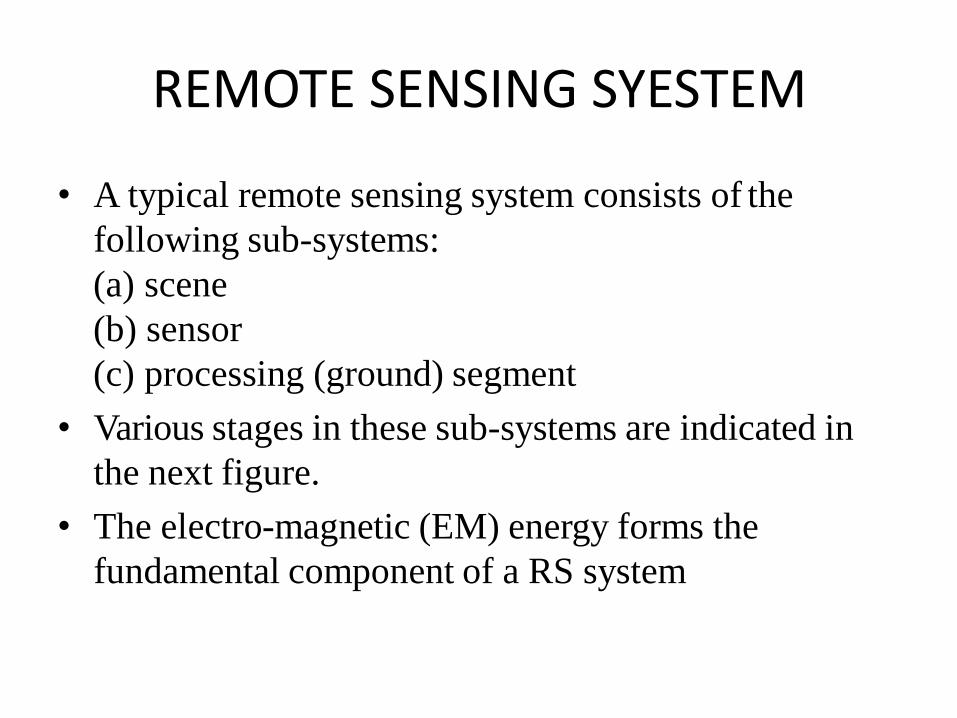
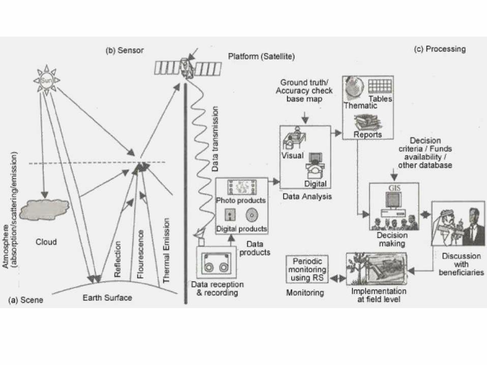
REMOTE SENSING SYESTEM
• A typical remote sensing system consists of the
following sub-systems:
(a) scene
(b) sensor
(c) processing (ground) segment
• Various stages in these sub-systems are indicated in
the next figure.
• The electro-magnetic (EM) energy forms the
fundamental component of a RS system
APPLICATION OF REMOTE SENSING
Agriculture:-
• Crop condition assessment.
• Crop yield estimation
Urban Planning:-
• Infrastructure mapping.
• Land use change detection.
• Future urban expansion planning

Thank You
New Government Polytechnic,Patna-13
PPT ON Aerial Photography

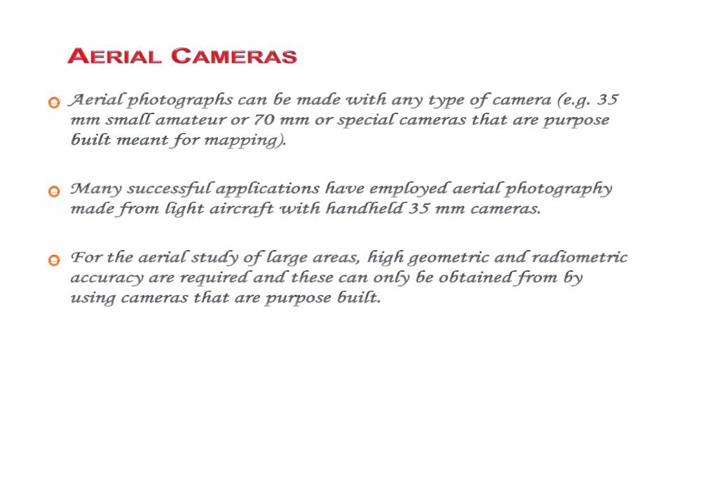
•
•
•
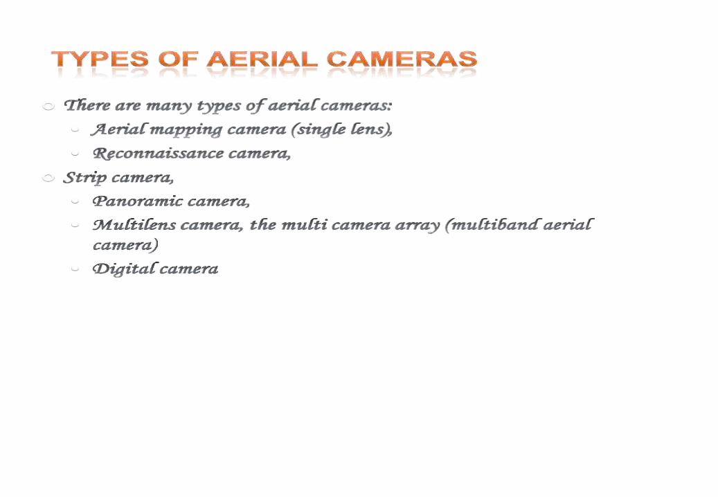
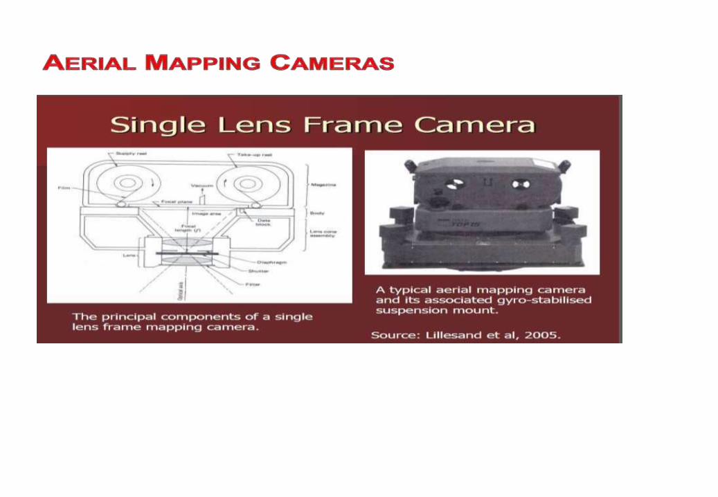
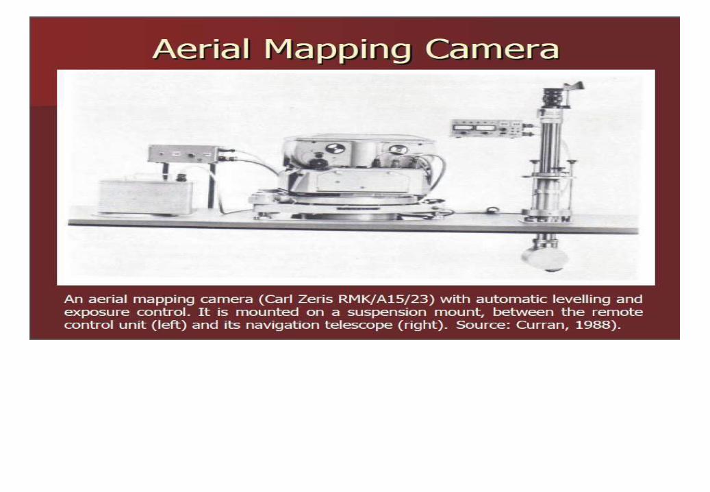

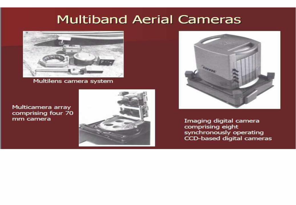
Aerial mapping cameras

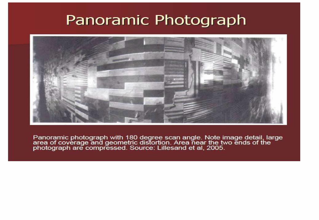


ANGULAR COVERAGE

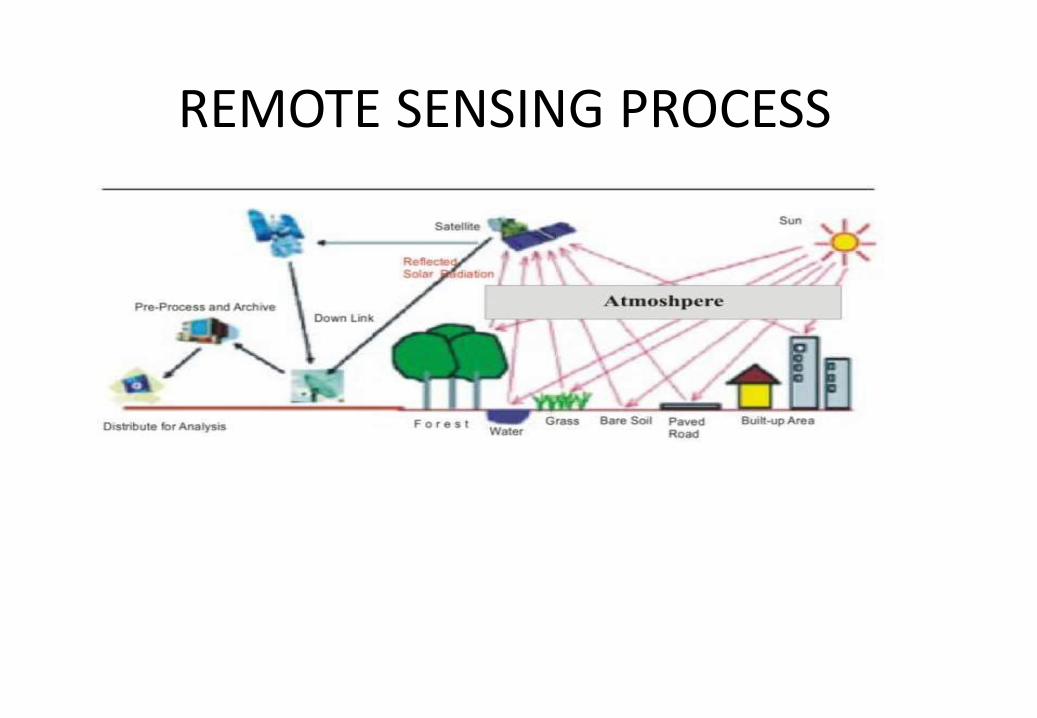
REMOTE SENSING PROCESS

2 8
CENTRE SENSOR

1.
2.

Thank You