Embed Size (px)
Citation preview
NEUTRINO FACTORIES AND BETA BEAMS*
Michael S. Zisman, Lawrence Berkeley National Laboratory, Berkeley, CA 94720 U.S.A.
Abstract In this paper we briefly review the concepts of Neutrino Factories and Beta Beam facilities, and indicate the main challenges in terms of beam performance and technological developments. We also describe the worldwide organizations that have embarked on defining and carrying out the necessary R&D on component design, beam simulations of facility performance, and benchmarking of key subsystems via actual beam tests. Currently approved subsystem tests include the Muon Ionization Cooling Experiment (MICE), under construction at Rutherford Appleton Laboratory, and the Mercury Intense Target (MERIT) experiment, to be carried out at CERN. These experiments are briefly described, and their schedules are indicated.
INTRODUCTION For some years now, there has been substantial effort on R&D towards a Neutrino Factory based on a muon storage ring [1–4]. More recently, studies have been initiated [5] on the innovative concept of the “Beta Beam” facility, which is based on a storage ring circulating a beta unstable ion, such as 6He or 18Ne.
The motivation for these facilities is to study the phenomenon of neutrino oscillations and, in particular, to provide the possibility to discover CP violation in the lepton sector. Neutrino oscillations imply that neutrinos have non-zero mass, and represent the first unambiguous evidence for physics beyond the Standard Model.
The beam properties of a muon-based Neutrino Factory are summarized in Eqs. (1) and (2). The muon decay kinematics are well known and νe → νµ oscillations give rise to easily detectable “wrong-sign” muons. The decay of a beta unstable nucleus is even simpler, giving rise to either an electron plus an electron anti-neutrino (β–) or a positron plus an electron neutrino (β+).
ννννµ µµ %50%50 +⇒→ ++eee (1)
ννννµ µµ %50%50 +⇒→ −−eee (2)
To study CP violation with a Neutrino Factory requires an intense beam of neutrinos aimed at a far detector that could be located as far as 7500 km from the storage ring. * Work supported by the Director, Office of Science, High Energy Physics, U. S. Department of Energy under Contract No. DE-AC02-05CH11231.
R&D ORGANIZATION Several groups worldwide have embarked on the design and supporting R&D for a Neutrino Factory. In the U.S., work is carried out by the Neutrino Factory and Muon Collider Collaboration (NFMCC) [6]. The NFMCC comprises several U.S. national laboratories and a number of universities in the U.S. and elsewhere. In Japan, work is carried out by the NUFACT-J collaboration [7], which includes KEK and several Japanese universities. In the UK, there is a UK Neutrino Factory (UKNF) collaboration [8]. In Europe, the R&D activities are being coordinated via the Beams for European Neutrino Experiments (BENE) network [9].
Over time, these separate efforts have learned to work together effectively as an informal international organization, thus avoiding unnecessary duplication. This coordination of the various regional R&D efforts has two main causes. First, the annual NuFact workshops [10] have facilitated the ability to communicate plans and results across regions, and second, the various regions are all short of resources to carry out the required R&D program on their own.
The Beta Beam design activity is presently a European effort, coordinated under the Eurisol task [11]. The group is centered at CERN and involves a number of European laboratories and universities. They are working toward a design study that will define the layout, the costs, and the performance of a Beta Beam facility.
MACHINE CONCEPTS
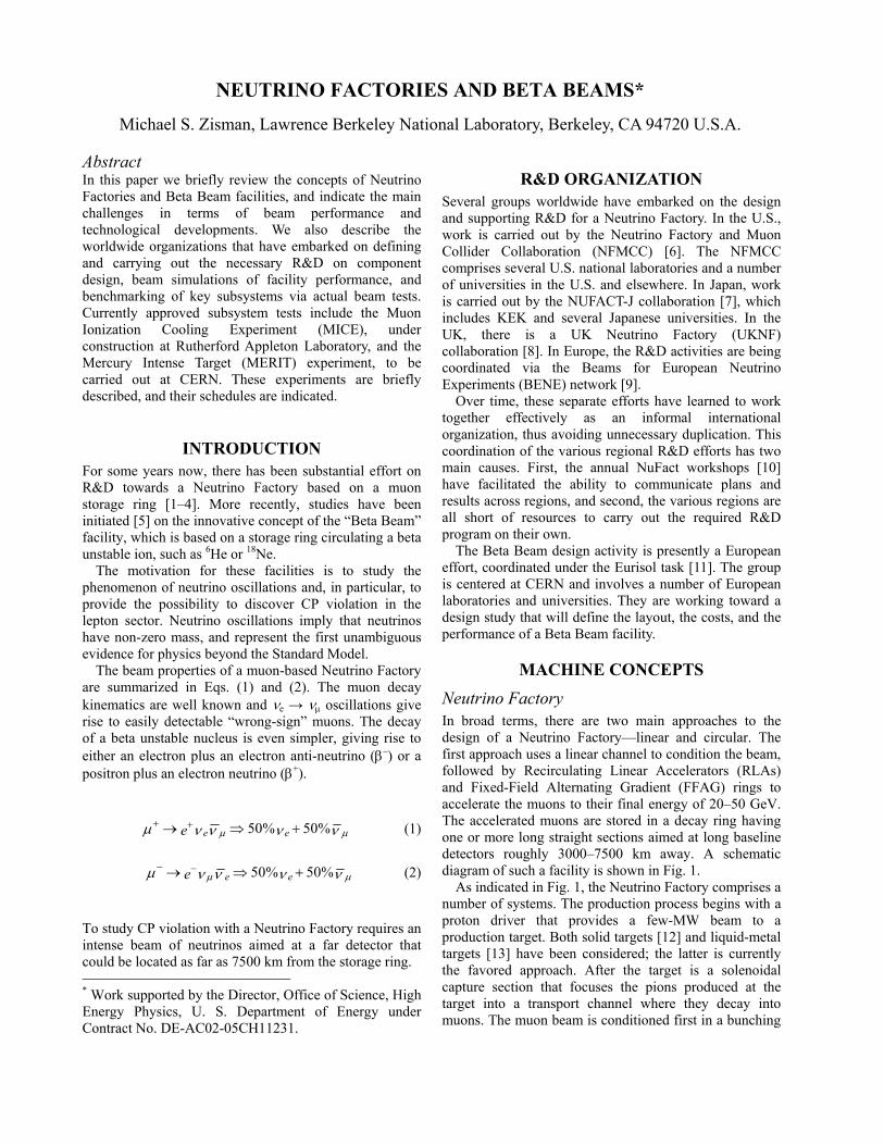
Neutrino Factory In broad terms, there are two main approaches to the design of a Neutrino Factory—linear and circular. The first approach uses a linear channel to condition the beam, followed by Recirculating Linear Accelerators (RLAs) and Fixed-Field Alternating Gradient (FFAG) rings to accelerate the muons to their final energy of 20–50 GeV. The accelerated muons are stored in a decay ring having one or more long straight sections aimed at long baseline detectors roughly 3000–7500 km away. A schematic diagram of such a facility is shown in Fig. 1.
As indicated in Fig. 1, the Neutrino Factory comprises a number of systems. The production process begins with a proton driver that provides a few-MW beam to a production target. Both solid targets [12] and liquid-metal targets [13] have been considered; the latter is currently the favored approach. After the target is a solenoidal capture section that focuses the pions produced at the target into a transport channel where they decay into muons. The muon beam is conditioned first in a bunching
Decay Channel
Linear Cooler
Buncher
1-4 MWProtonSource
Hg-Jet Target
Pre-Accelerator
Acceleration
DecayRing ~ 1 km5-10
GeV
10-20GeV
1.5-5 GeV
νDecay Channel
Linear Cooler
Buncher
1-4 MWProtonSource
Hg-Jet Target
Pre-Accelerator
Acceleration
DecayRing ~ 1 km5-10
GeV
10-20GeV
1.5-5 GeV
ν
Figure 1: Schematic layout of linear style Neutrino Factory based on Ref. [14].
and phase rotation section, where the beam energy spread is reduced. The resulting ≈200 MeV/c muon beam then passes through a cooling channel having LiH absorbers interleaved with 201-MHz RF cavities contained in a solenoidal focusing system. The cooling channel reduces the transverse emittance of the muon beam, making it suitable for acceleration to the working energy of 20 GeV. The presently favored acceleration scheme [14] makes use of a linac to reach 1.5 GeV, followed by a dogbone RLA to accelerate the muons to 5 GeV. The final stages of acceleration make use of so-called non-scaling FFAG rings that accelerate the beam from 5–10 and from 10–20 GeV, respectively. Thereafter, the beam is stored in a racetrack ring with a long straight section aimed at a detector some 3000 km distant.
The “circular” scheme [3] uses a cascaded series of scaling FFAG rings to accelerate the beam from the target to its final energy of 20 GeV. Taking advantage of the large longitudinal acceptance of a 5 MHz RF system, and the large transverse acceptance of the FFAGs, the design does not employ cooling of the beam.
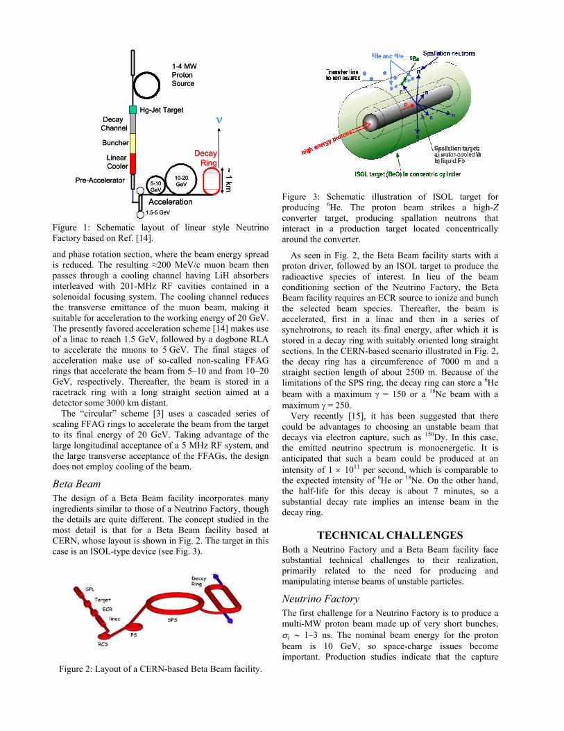
Beta Beam The design of a Beta Beam facility incorporates many ingredients similar to those of a Neutrino Factory, though the details are quite different. The concept studied in the most detail is that for a Beta Beam facility based at CERN, whose layout is shown in Fig. 2. The target in this case is an ISOL-type device (see Fig. 3).
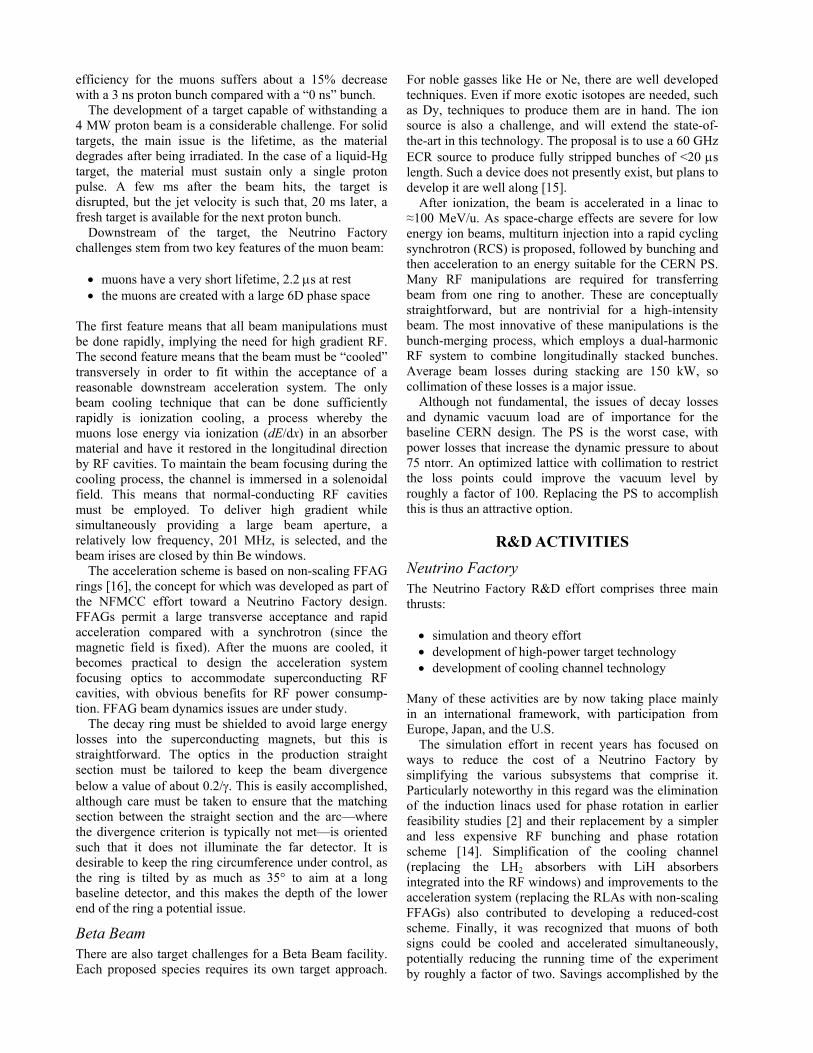
Figure 2: Layout of a CERN-based Beta Beam facility.
Figure 3: Schematic illustration of ISOL target for producing 6He. The proton beam strikes a high-Z converter target, producing spallation neutrons that interact in a production target located concentrically around the converter.
As seen in Fig. 2, the Beta Beam facility starts with a proton driver, followed by an ISOL target to produce the radioactive species of interest. In lieu of the beam conditioning section of the Neutrino Factory, the Beta Beam facility requires an ECR source to ionize and bunch the selected beam species. Thereafter, the beam is accelerated, first in a linac and then in a series of synchrotrons, to reach its final energy, after which it is stored in a decay ring with suitably oriented long straight sections. In the CERN-based scenario illustrated in Fig. 2, the decay ring has a circumference of 7000 m and a straight section length of about 2500 m. Because of the limitations of the SPS ring, the decay ring can store a 6He beam with a maximum γ = 150 or a 18Ne beam with a maximum γ = 250.
Very recently [15], it has been suggested that there could be advantages to choosing an unstable beam that decays via electron capture, such as 150Dy. In this case, the emitted neutrino spectrum is monoenergetic. It is anticipated that such a beam could be produced at an intensity of 1 × 10¹¹ per second, which is comparable to the expected intensity of 6He or 18Ne. On the other hand, the half-life for this decay is about 7 minutes, so a substantial decay rate implies an intense beam in the decay ring.
TECHNICAL CHALLENGES Both a Neutrino Factory and a Beta Beam facility face substantial technical challenges to their realization, primarily related to the need for producing and manipulating intense beams of unstable particles.
Neutrino Factory The first challenge for a Neutrino Factory is to produce a multi-MW proton beam made up of very short bunches, σl ∼ 1–3 ns. The nominal beam energy for the proton beam is 10 GeV, so space-charge issues become important. Production studies indicate that the capture
efficiency for the muons suffers about a 15% decrease with a 3 ns proton bunch compared with a “0 ns” bunch.
The development of a target capable of withstanding a 4 MW proton beam is a considerable challenge. For solid targets, the main issue is the lifetime, as the material degrades after being irradiated. In the case of a liquid-Hg target, the material must sustain only a single proton pulse. A few ms after the beam hits, the target is disrupted, but the jet velocity is such that, 20 ms later, a fresh target is available for the next proton bunch.
Downstream of the target, the Neutrino Factory challenges stem from two key features of the muon beam:
• muons have a very short lifetime, 2.2 µs at rest • the muons are created with a large 6D phase space
The first feature means that all beam manipulations must be done rapidly, implying the need for high gradient RF. The second feature means that the beam must be “cooled” transversely in order to fit within the acceptance of a reasonable downstream acceleration system. The only beam cooling technique that can be done sufficiently rapidly is ionization cooling, a process whereby the muons lose energy via ionization (dE/dx) in an absorber material and have it restored in the longitudinal direction by RF cavities. To maintain the beam focusing during the cooling process, the channel is immersed in a solenoidal field. This means that normal-conducting RF cavities must be employed. To deliver high gradient while simultaneously providing a large beam aperture, a relatively low frequency, 201 MHz, is selected, and the beam irises are closed by thin Be windows.
The acceleration scheme is based on non-scaling FFAG rings [16], the concept for which was developed as part of the NFMCC effort toward a Neutrino Factory design. FFAGs permit a large transverse acceptance and rapid acceleration compared with a synchrotron (since the magnetic field is fixed). After the muons are cooled, it becomes practical to design the acceleration system focusing optics to accommodate superconducting RF cavities, with obvious benefits for RF power consump-tion. FFAG beam dynamics issues are under study.
The decay ring must be shielded to avoid large energy losses into the superconducting magnets, but this is straightforward. The optics in the production straight section must be tailored to keep the beam divergence below a value of about 0.2/γ. This is easily accomplished, although care must be taken to ensure that the matching section between the straight section and the arc—where the divergence criterion is typically not met—is oriented such that it does not illuminate the far detector. It is desirable to keep the ring circumference under control, as the ring is tilted by as much as 35° to aim at a long baseline detector, and this makes the depth of the lower end of the ring a potential issue.
Beta Beam There are also target challenges for a Beta Beam facility. Each proposed species requires its own target approach.
For noble gasses like He or Ne, there are well developed techniques. Even if more exotic isotopes are needed, such as Dy, techniques to produce them are in hand. The ion source is also a challenge, and will extend the state-of-the-art in this technology. The proposal is to use a 60 GHz ECR source to produce fully stripped bunches of <20 µs length. Such a device does not presently exist, but plans to develop it are well along [15].
After ionization, the beam is accelerated in a linac to ≈100 MeV/u. As space-charge effects are severe for low energy ion beams, multiturn injection into a rapid cycling synchrotron (RCS) is proposed, followed by bunching and then acceleration to an energy suitable for the CERN PS. Many RF manipulations are required for transferring beam from one ring to another. These are conceptually straightforward, but are nontrivial for a high-intensity beam. The most innovative of these manipulations is the bunch-merging process, which employs a dual-harmonic RF system to combine longitudinally stacked bunches. Average beam losses during stacking are 150 kW, so collimation of these losses is a major issue.
Although not fundamental, the issues of decay losses and dynamic vacuum load are of importance for the baseline CERN design. The PS is the worst case, with power losses that increase the dynamic pressure to about 75 ntorr. An optimized lattice with collimation to restrict the loss points could improve the vacuum level by roughly a factor of 100. Replacing the PS to accomplish this is thus an attractive option.
R&D ACTIVITIES
Neutrino Factory The Neutrino Factory R&D effort comprises three main thrusts: • simulation and theory effort • development of high-power target technology • development of cooling channel technology
Many of these activities are by now taking place mainly in an international framework, with participation from Europe, Japan, and the U.S.
The simulation effort in recent years has focused on ways to reduce the cost of a Neutrino Factory by simplifying the various subsystems that comprise it. Particularly noteworthy in this regard was the elimination of the induction linacs used for phase rotation in earlier feasibility studies [2] and their replacement by a simpler and less expensive RF bunching and phase rotation scheme [14]. Simplification of the cooling channel (replacing the LH2 absorbers with LiH absorbers integrated into the RF windows) and improvements to the acceleration system (replacing the RLAs with non-scaling FFAGs) also contributed to developing a reduced-cost scheme. Finally, it was recognized that muons of both signs could be cooled and accelerated simultaneously, potentially reducing the running time of the experiment by roughly a factor of two. Savings accomplished by the
simulation group were roughly 35% compared with the cost estimate in Ref. [2].
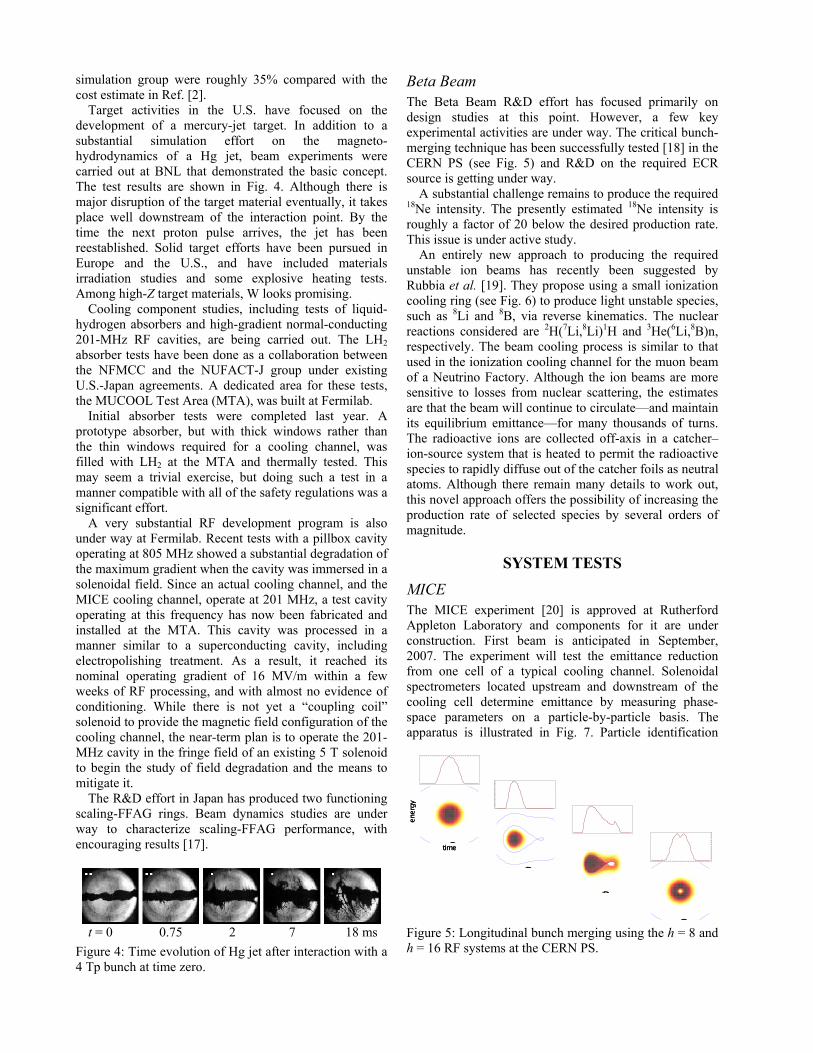
Target activities in the U.S. have focused on the development of a mercury-jet target. In addition to a substantial simulation effort on the magneto-hydrodynamics of a Hg jet, beam experiments were carried out at BNL that demonstrated the basic concept. The test results are shown in Fig. 4. Although there is major disruption of the target material eventually, it takes place well downstream of the interaction point. By the time the next proton pulse arrives, the jet has been reestablished. Solid target efforts have been pursued in Europe and the U.S., and have included materials irradiation studies and some explosive heating tests. Among high-Z target materials, W looks promising.
Cooling component studies, including tests of liquid-hydrogen absorbers and high-gradient normal-conducting 201-MHz RF cavities, are being carried out. The LH2 absorber tests have been done as a collaboration between the NFMCC and the NUFACT-J group under existing U.S.-Japan agreements. A dedicated area for these tests, the MUCOOL Test Area (MTA), was built at Fermilab.
Initial absorber tests were completed last year. A prototype absorber, but with thick windows rather than the thin windows required for a cooling channel, was filled with LH2 at the MTA and thermally tested. This may seem a trivial exercise, but doing such a test in a manner compatible with all of the safety regulations was a significant effort.
A very substantial RF development program is also under way at Fermilab. Recent tests with a pillbox cavity operating at 805 MHz showed a substantial degradation of the maximum gradient when the cavity was immersed in a solenoidal field. Since an actual cooling channel, and the MICE cooling channel, operate at 201 MHz, a test cavity operating at this frequency has now been fabricated and installed at the MTA. This cavity was processed in a manner similar to a superconducting cavity, including electropolishing treatment. As a result, it reached its nominal operating gradient of 16 MV/m within a few weeks of RF processing, and with almost no evidence of conditioning. While there is not yet a “coupling coil” solenoid to provide the magnetic field configuration of the cooling channel, the near-term plan is to operate the 201-MHz cavity in the fringe field of an existing 5 T solenoid to begin the study of field degradation and the means to mitigate it.
The R&D effort in Japan has produced two functioning scaling-FFAG rings. Beam dynamics studies are under way to characterize scaling-FFAG performance, with encouraging results [17].
t = 0 0.75 2 7 18 ms
Figure 4: Time evolution of Hg jet after interaction with a 4 Tp bunch at time zero.
Beta Beam The Beta Beam R&D effort has focused primarily on design studies at this point. However, a few key experimental activities are under way. The critical bunch-merging technique has been successfully tested [18] in the CERN PS (see Fig. 5) and R&D on the required ECR source is getting under way.
A substantial challenge remains to produce the required 18Ne intensity. The presently estimated 18Ne intensity is roughly a factor of 20 below the desired production rate. This issue is under active study.
An entirely new approach to producing the required unstable ion beams has recently been suggested by Rubbia et al. [19]. They propose using a small ionization cooling ring (see Fig. 6) to produce light unstable species, such as 8Li and 8B, via reverse kinematics. The nuclear reactions considered are 2H(7Li,8Li)1H and 3He(6Li,8B)n, respectively. The beam cooling process is similar to that used in the ionization cooling channel for the muon beam of a Neutrino Factory. Although the ion beams are more sensitive to losses from nuclear scattering, the estimates are that the beam will continue to circulate—and maintain its equilibrium emittance—for many thousands of turns. The radioactive ions are collected off-axis in a catcher–ion-source system that is heated to permit the radioactive species to rapidly diffuse out of the catcher foils as neutral atoms. Although there remain many details to work out, this novel approach offers the possibility of increasing the production rate of selected species by several orders of magnitude.
SYSTEM TESTS
MICE The MICE experiment [20] is approved at Rutherford Appleton Laboratory and components for it are under construction. First beam is anticipated in September, 2007. The experiment will test the emittance reduction from one cell of a typical cooling channel. Solenoidal spectrometers located upstream and downstream of the cooling cell determine emittance by measuring phase-space parameters on a particle-by-particle basis. The apparatus is illustrated in Fig. 7. Particle identification
@D
@D
@D
@Dtime
energy
@D
@D
@D
@Dtime
energy
Figure 5: Longitudinal bunch merging using the h = 8 and h = 16 RF systems at the CERN PS.
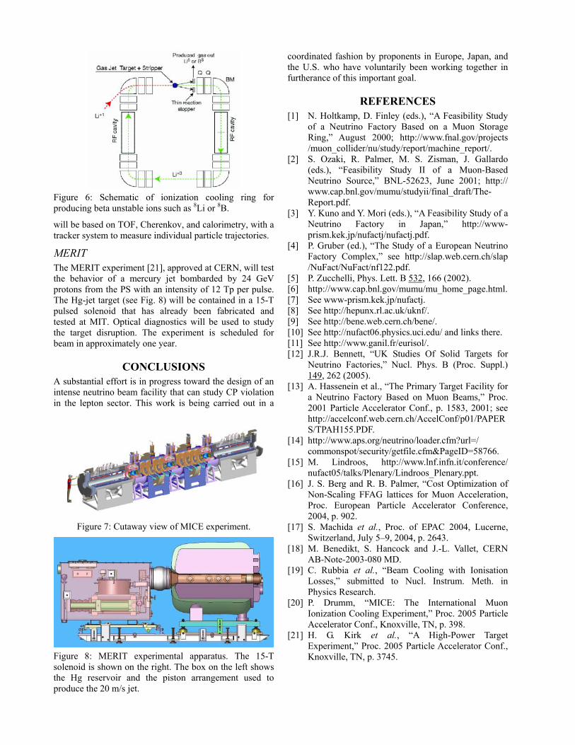
Figure 6: Schematic of ionization cooling ring for producing beta unstable ions such as 8Li or 8B.
will be based on TOF, Cherenkov, and calorimetry, with a tracker system to measure individual particle trajectories.
MERIT The MERIT experiment [21], approved at CERN, will test the behavior of a mercury jet bombarded by 24 GeV protons from the PS with an intensity of 12 Tp per pulse. The Hg-jet target (see Fig. 8) will be contained in a 15-T pulsed solenoid that has already been fabricated and tested at MIT. Optical diagnostics will be used to study the target disruption. The experiment is scheduled for beam in approximately one year.
CONCLUSIONS A substantial effort is in progress toward the design of an intense neutrino beam facility that can study CP violation in the lepton sector. This work is being carried out in a
Figure 7: Cutaway view of MICE experiment.
Figure 8: MERIT experimental apparatus. The 15-T solenoid is shown on the right. The box on the left shows the Hg reservoir and the piston arrangement used to produce the 20 m/s jet.
coordinated fashion by proponents in Europe, Japan, and the U.S. who have voluntarily been working together in furtherance of this important goal.
REFERENCES [1] N. Holtkamp, D. Finley (eds.), “A Feasibility Study
of a Neutrino Factory Based on a Muon Storage Ring,” August 2000; http://www.fnal.gov/projects /muon_collider/nu/study/report/machine_report/.
[2] S. Ozaki, R. Palmer, M. S. Zisman, J. Gallardo (eds.), “Feasibility Study II of a Muon-Based Neutrino Source,” BNL-52623, June 2001; http:// www.cap.bnl.gov/mumu/studyii/final_draft/The-Report.pdf.
[3] Y. Kuno and Y. Mori (eds.), “A Feasibility Study of a Neutrino Factory in Japan,” http://www-prism.kek.jp/nufactj/nufactj.pdf.
[4] P. Gruber (ed.), “The Study of a European Neutrino Factory Complex,” see http://slap.web.cern.ch/slap /NuFact/NuFact/nf122.pdf.
[5] P. Zucchelli, Phys. Lett. B 532, 166 (2002). [6] http://www.cap.bnl.gov/mumu/mu_home_page.html. [7] See www-prism.kek.jp/nufactj. [8] See http://hepunx.rl.ac.uk/uknf/. [9] See http://bene.web.cern.ch/bene/. [10] See http://nufact06.physics.uci.edu/ and links there. [11] See http://www.ganil.fr/eurisol/. [12] J.R.J. Bennett, “UK Studies Of Solid Targets for
Neutrino Factories,” Nucl. Phys. B (Proc. Suppl.) 149, 262 (2005).
[13] A. Hassenein et al., “The Primary Target Facility for a Neutrino Factory Based on Muon Beams,” Proc. 2001 Particle Accelerator Conf., p. 1583, 2001; see http://accelconf.web.cern.ch/AccelConf/p01/PAPERS/TPAH155.PDF.
[14] http://www.aps.org/neutrino/loader.cfm?url=/ commonspot/security/getfile.cfm&PageID=58766.
[15] M. Lindroos, http://www.lnf.infn.it/conference/ nufact05/talks/Plenary/Lindroos_Plenary.ppt.
[16] J. S. Berg and R. B. Palmer, “Cost Optimization of Non-Scaling FFAG lattices for Muon Acceleration, Proc. European Particle Accelerator Conference, 2004, p. 902.
[17] S. Machida et al., Proc. of EPAC 2004, Lucerne, Switzerland, July 5–9, 2004, p. 2643.
[18] M. Benedikt, S. Hancock and J.-L. Vallet, CERN AB-Note-2003-080 MD.
[19] C. Rubbia et al., “Beam Cooling with Ionisation Losses,” submitted to Nucl. Instrum. Meth. in Physics Research.
[20] P. Drumm, “MICE: The International Muon Ionization Cooling Experiment,” Proc. 2005 Particle Accelerator Conf., Knoxville, TN, p. 398.
[21] H. G. Kirk et al., “A High-Power Target Experiment,” Proc. 2005 Particle Accelerator Conf., Knoxville, TN, p. 3745.