Embed Size (px)
Citation preview
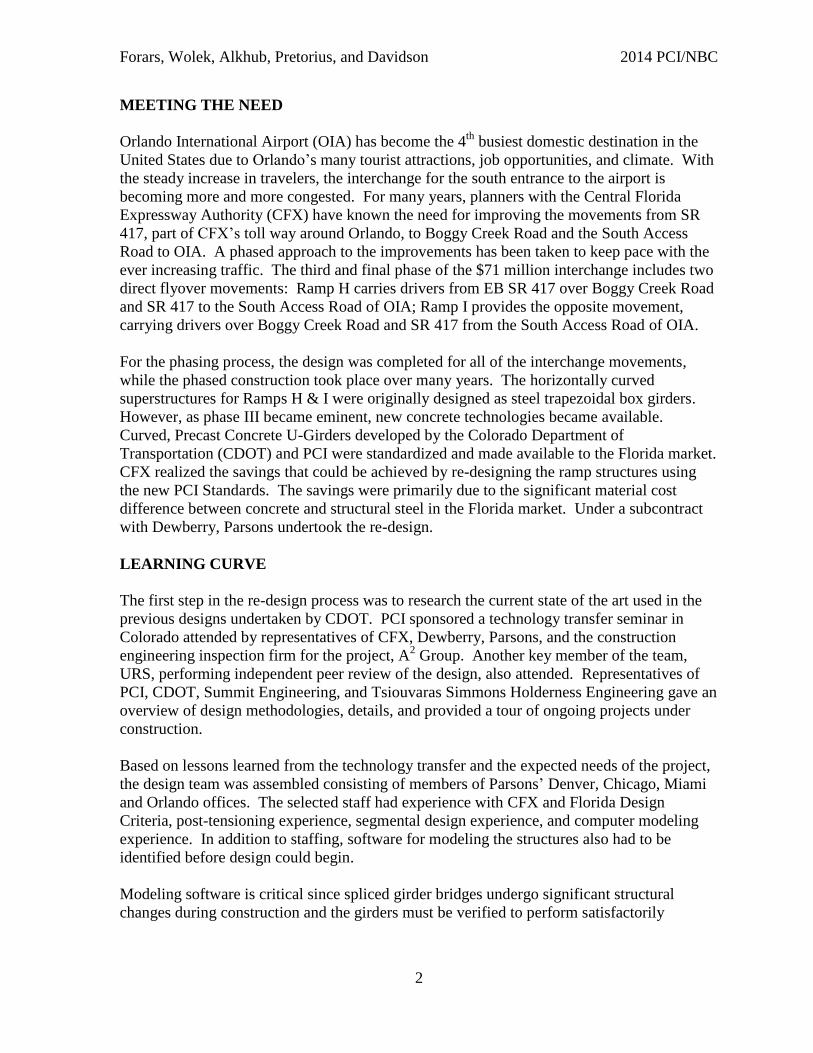
Forars, Wolek, Alkhub, Pretorius, and Davidson 2014 PCI/NBC
DESIGN AND CONSTRUCTION OF FLORIDA’S FIRST SPLICED CURVED
CONCRETE U-GIRDER BRIDGES: THE SR 417 AND BOGGY CREEK ROAD
INTERCHANGE
P. Kristian Forars, PE, Parsons, Denver, CO
Arthur Wolek, PE, Parsons, Miami, FL
Jessica Alkhub, PE, Parsons, Orlando, FL
David N. Pretorius, EI, Parsons, Orlando, FL
Thomas E. Davidson, PE, Parsons, Orlando, FL
ABSTRACT
The new SR417 and Boggy Creek road interchange, which will soon begin
construction, includes two new bridges employing spliced post-tensioned curved concrete U-
girders. These systems have been extensively used in Colorado, but have yet to be
constructed in Florida. Fly-over ramps were initially designed with steel box girders, but
spliced precast concrete U-girders were eventually selected as an economical alternative.
During the design phases of this design/bid/build project, coordination with PCI, the
Colorado DOT, and other design firms was integral to developing economical design details,
taking advantage of experience gained from previously completed projects.
Fly-over ramps had varying span lengths up to 220’, total lengths between 1411’ and
2708’, and a minimum horizontal radius of 955’. A full 3D computer model was developed
using the RM Bridge software package, which had the capability to analyze static and time-
dependent loading conditions resulting from the staging and erection sequences required
during construction. The project utilizes standard cross-sections and details developed and
published by PCI. This paper will discuss general details of the two bridges, the analysis
procedures that were used, and the lessons learned from the design and production process
of Florida’s first set of spliced post-tensioned curved concrete U-girder bridges.
Keywords: Florida, Interchange, Curved, Concrete, U-Girder, Bridge.
Forars, Wolek, Alkhub, Pretorius, and Davidson 2014 PCI/NBC
2
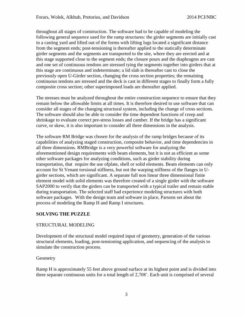
MEETING THE NEED
Orlando International Airport (OIA) has become the 4th
busiest domestic destination in the
United States due to Orlando’s many tourist attractions, job opportunities, and climate. With
the steady increase in travelers, the interchange for the south entrance to the airport is
becoming more and more congested. For many years, planners with the Central Florida
Expressway Authority (CFX) have known the need for improving the movements from SR
417, part of CFX’s toll way around Orlando, to Boggy Creek Road and the South Access
Road to OIA. A phased approach to the improvements has been taken to keep pace with the
ever increasing traffic. The third and final phase of the $71 million interchange includes two
direct flyover movements: Ramp H carries drivers from EB SR 417 over Boggy Creek Road
and SR 417 to the South Access Road of OIA; Ramp I provides the opposite movement,
carrying drivers over Boggy Creek Road and SR 417 from the South Access Road of OIA.
For the phasing process, the design was completed for all of the interchange movements,
while the phased construction took place over many years. The horizontally curved
superstructures for Ramps H & I were originally designed as steel trapezoidal box girders.
However, as phase III became eminent, new concrete technologies became available.
Curved, Precast Concrete U-Girders developed by the Colorado Department of
Transportation (CDOT) and PCI were standardized and made available to the Florida market.
CFX realized the savings that could be achieved by re-designing the ramp structures using
the new PCI Standards. The savings were primarily due to the significant material cost
difference between concrete and structural steel in the Florida market. Under a subcontract
with Dewberry, Parsons undertook the re-design.
LEARNING CURVE
The first step in the re-design process was to research the current state of the art used in the
previous designs undertaken by CDOT. PCI sponsored a technology transfer seminar in
Colorado attended by representatives of CFX, Dewberry, Parsons, and the construction
engineering inspection firm for the project, A2 Group. Another key member of the team,
URS, performing independent peer review of the design, also attended. Representatives of
PCI, CDOT, Summit Engineering, and Tsiouvaras Simmons Holderness Engineering gave an
overview of design methodologies, details, and provided a tour of ongoing projects under
construction.
Based on lessons learned from the technology transfer and the expected needs of the project,
the design team was assembled consisting of members of Parsons’ Denver, Chicago, Miami
and Orlando offices. The selected staff had experience with CFX and Florida Design
Criteria, post-tensioning experience, segmental design experience, and computer modeling
experience. In addition to staffing, software for modeling the structures also had to be
identified before design could begin.
Modeling software is critical since spliced girder bridges undergo significant structural
changes during construction and the girders must be verified to perform satisfactorily
Forars, Wolek, Alkhub, Pretorius, and Davidson 2014 PCI/NBC
3
throughout all stages of construction. The software had to be capable of modeling the
following general sequence used for the ramp structures: the girder segments are initially cast
in a casting yard and lifted out of the forms with lifting lugs located a significant distance
from the segment ends; post-tensioning is thereafter applied to the statically determinate
girder segments and the segments are transported to the site, where they are erected and at
this stage supported close to the segment ends; the closure pours and the diaphragms are cast
and one set of continuous tendons are stressed tying the segments together into girders that at
this stage are continuous and indeterminate; a lid slab is thereafter cast to close the
previously open U-Girder section, changing the cross section properties; the remaining
continuous tendons are stressed and the deck is cast in different stages to finally form a fully
composite cross section; other superimposed loads are thereafter applied.
The stresses must be analyzed throughout the entire construction sequence to ensure that they
remain below the allowable limits at all times. It is therefore desired to use software that can
consider all stages of the changing structural system, including the change of cross sections.
The software should also be able to consider the time dependent functions of creep and
shrinkage to evaluate correct pre-stress losses and camber. If the bridge has a significant
curve, or skew, it is also important to consider all three dimensions in the analysis.
The software RM Bridge was chosen for the analysis of the ramp bridges because of its
capabilities of analyzing staged construction, composite behavior, and time dependencies in
all three dimensions. RMBridge is a very powerful software for analyzing the
aforementioned design requirements with beam elements, but it is not as efficient as some
other software packages for analyzing conditions, such as girder stability during
transportation, that require the use ofplate, shell or solid elements. Beam elements can only
account for St Venant torsional stiffness, but not the warping stiffness of the flanges in U-
girder sections, which are significant. A separate full non linear three dimensional finite
element model with solid elements was therefore created of a single girder with the software
SAP2000 to verify that the girders can be transported with a typical trailer and remain stable
during transportation. The selected staff had experience modeling structures with both
software packages. With the design team and software in place, Parsons set about the
process of modeling the Ramp H and Ramp I structures.
SOLVING THE PUZZLE
STRUCTURAL MODELING
Development of the structural model required input of geometry, generation of the various
structural elements, loading, post-tensioning application, and sequencing of the analysis to
simulate the construction process.
Geometry
Ramp H is approximately 55 feet above ground surface at its highest point and is divided into
three separate continuous units for a total length of 2,708’. Each unit is comprised of several
Forars, Wolek, Alkhub, Pretorius, and Davidson 2014 PCI/NBC
4
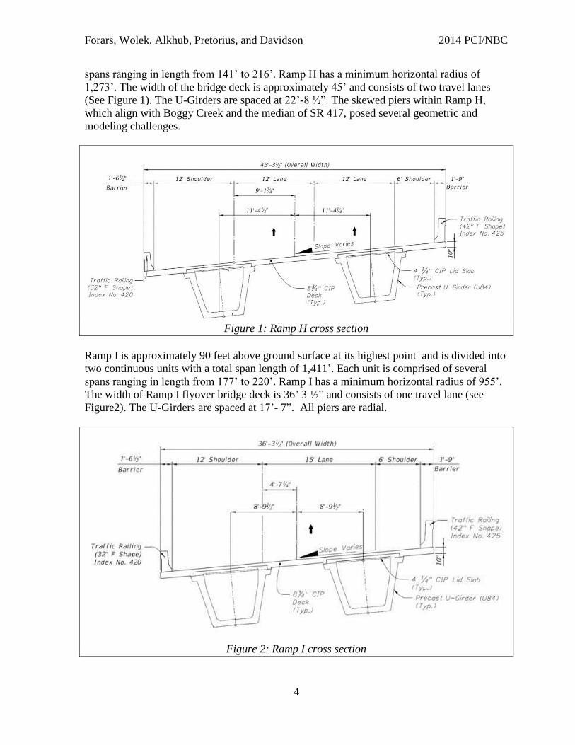
spans ranging in length from 141’ to 216’. Ramp H has a minimum horizontal radius of
1,273’. The width of the bridge deck is approximately 45’ and consists of two travel lanes
(See Figure 1). The U-Girders are spaced at 22’-8 ½”. The skewed piers within Ramp H,
which align with Boggy Creek and the median of SR 417, posed several geometric and
modeling challenges.
Figure 1: Ramp H cross section
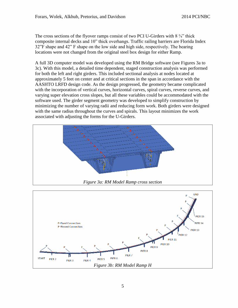
Ramp I is approximately 90 feet above ground surface at its highest point and is divided into
two continuous units with a total span length of 1,411’. Each unit is comprised of several
spans ranging in length from 177’ to 220’. Ramp I has a minimum horizontal radius of 955’.
The width of Ramp I flyover bridge deck is 36’ 3 ½” and consists of one travel lane (see
Figure2). The U-Girders are spaced at 17’- 7”. All piers are radial.
Figure 2: Ramp I cross section
Forars, Wolek, Alkhub, Pretorius, and Davidson 2014 PCI/NBC
5
The cross sections of the flyover ramps consist of two PCI U-Girders with 8 ¾” thick
composite internal decks and 10” thick overhangs. Traffic railing barriers are Florida Index
32”F shape and 42” F shape on the low side and high side, respectively. The bearing
locations were not changed from the original steel box design for either Ramp.
A full 3D computer model was developed using the RM Bridge software (see Figures 3a to
3c). With this model, a detailed time dependent, staged construction analysis was performed
for both the left and right girders. This included sectional analysis at nodes located at
approximately 5 feet on center and at critical sections in the span in accordance with the
AASHTO LRFD design code. As the design progressed, the geometry became complicated
with the incorporation of vertical curves, horizontal curves, spiral curves, reverse curves, and
varying super elevation cross slopes, but all these variables could be accommodated with the
software used. The girder segment geometry was developed to simplify construction by
minimizing the number of varying radii and reducing form work. Both girders were designed
with the same radius throughout the curves and spirals. This layout minimizes the work
associated with adjusting the forms for the U-Girders.
Figure 3a: RM Model Ramp cross section
Figure 3b: RM Model Ramp H
Forars, Wolek, Alkhub, Pretorius, and Davidson 2014 PCI/NBC
6
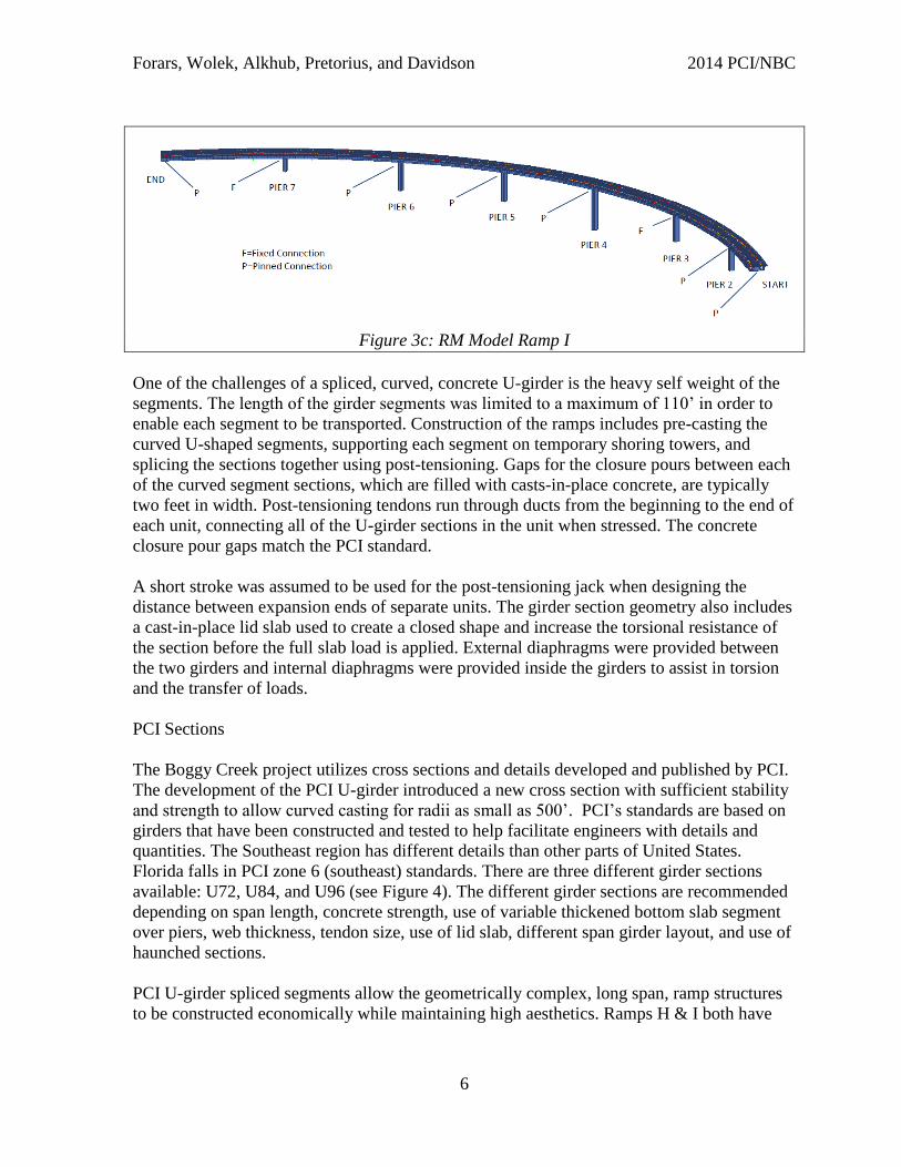
Figure 3c: RM Model Ramp I
One of the challenges of a spliced, curved, concrete U-girder is the heavy self weight of the
segments. The length of the girder segments was limited to a maximum of 110’ in order to
enable each segment to be transported. Construction of the ramps includes pre-casting the
curved U-shaped segments, supporting each segment on temporary shoring towers, and
splicing the sections together using post-tensioning. Gaps for the closure pours between each
of the curved segment sections, which are filled with casts-in-place concrete, are typically
two feet in width. Post-tensioning tendons run through ducts from the beginning to the end of
each unit, connecting all of the U-girder sections in the unit when stressed. The concrete
closure pour gaps match the PCI standard.
A short stroke was assumed to be used for the post-tensioning jack when designing the
distance between expansion ends of separate units. The girder section geometry also includes
a cast-in-place lid slab used to create a closed shape and increase the torsional resistance of
the section before the full slab load is applied. External diaphragms were provided between
the two girders and internal diaphragms were provided inside the girders to assist in torsion
and the transfer of loads.
PCI Sections
The Boggy Creek project utilizes cross sections and details developed and published by PCI.
The development of the PCI U-girder introduced a new cross section with sufficient stability
and strength to allow curved casting for radii as small as 500’. PCI’s standards are based on
girders that have been constructed and tested to help facilitate engineers with details and
quantities. The Southeast region has different details than other parts of United States.
Florida falls in PCI zone 6 (southeast) standards. There are three different girder sections
available: U72, U84, and U96 (see Figure 4). The different girder sections are recommended
depending on span length, concrete strength, use of variable thickened bottom slab segment
over piers, web thickness, tendon size, use of lid slab, different span girder layout, and use of
haunched sections.
PCI U-girder spliced segments allow the geometrically complex, long span, ramp structures
to be constructed economically while maintaining high aesthetics. Ramps H & I both have
Forars, Wolek, Alkhub, Pretorius, and Davidson 2014 PCI/NBC
7
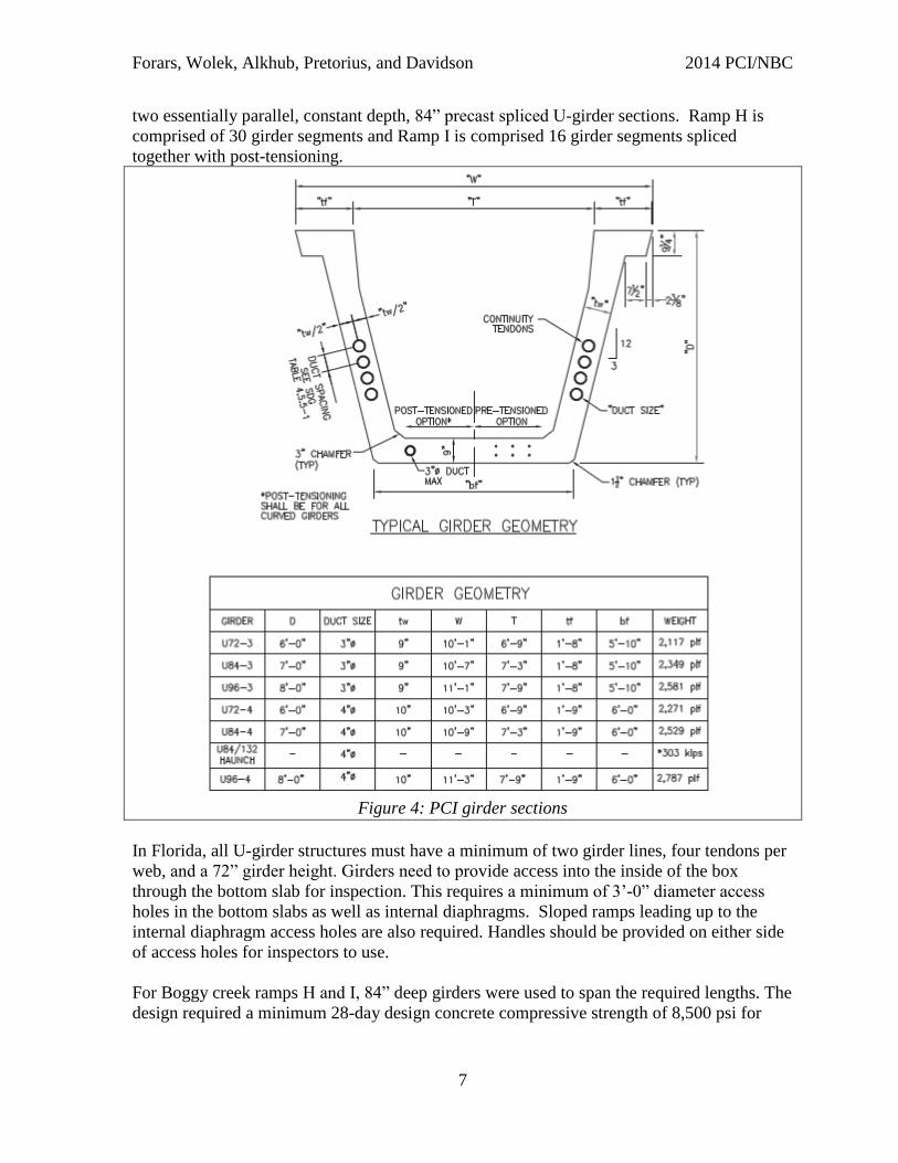
two essentially parallel, constant depth, 84” precast spliced U-girder sections. Ramp H is
comprised of 30 girder segments and Ramp I is comprised 16 girder segments spliced
together with post-tensioning.
Figure 4: PCI girder sections
In Florida, all U-girder structures must have a minimum of two girder lines, four tendons per
web, and a 72” girder height. Girders need to provide access into the inside of the box
through the bottom slab for inspection. This requires a minimum of 3’-0” diameter access
holes in the bottom slabs as well as internal diaphragms. Sloped ramps leading up to the
internal diaphragm access holes are also required. Handles should be provided on either side
of access holes for inspectors to use.
For Boggy creek ramps H and I, 84” deep girders were used to span the required lengths. The
design required a minimum 28-day design concrete compressive strength of 8,500 psi for
Forars, Wolek, Alkhub, Pretorius, and Davidson 2014 PCI/NBC
8
both the girder segments and closure pours. The precast U-Girder segments ultimately
require a cast-in-place lid slab to increase the torsional resistance of the section during
construction. Web thickness is 10” to accommodate the 4” OD ducts for the 15 strand
tendons. Due to the heavy weight of the U-84 section (2,529 plf ), the maximum length of the
girder segments had to be limited to 110’. A variable bottom flange is used throughout the
girder line and varies from 9” to 1’9” over the piers to provide additional capacity to meet
allowable stresses over the pier.
The bottom flange of the section provides enough room for post-tensioning tendons. Boggy
Creek Ramp H and I had either four strand flat ducts or twelve strand round polyethylene
ducts in the bottom flange depending on girder segment lengths. The bottom tendons are
used to facilitate in carrying its heavy self weight. The U-girder top flange also provides
room for top post-tensioning strands if needed. Boggy Creek has 15 strand (which utilizes 19
strand anchors) post-tensioning ducts through the top flange to assist maintaining allowable
tensile stresses over the piers. The U-girder section also has four continuity tendons (each 15
strands with 19 strand anchors) running throughout the girder web from beginning to end of
unit. The continuity tendons stitch all the girder segments together. The post-tensioning
strand configurations throughout the girder lines are designed to keep the stresses, service III
tension, and service I compression, within allowable limits at various stages of construction.
Loads
Design was done in accordance with AASHTO LRFD Bridge design specifications 5th
edition with 2010 interim revisions. Service load effects were factored based on AASHTO
LRFD load tables to determine the ultimate demands at critical sections. A three dimensional
computer analysis was performed at nodes located at nearly 5 ft on center and at critical
sections in the span in accordance with the AASHTO design code. Areas of interest in the
analysis include stresses through the different stages of life of the bridge and moment and
stress capacities of critical sections.
The self weight of the concrete box girder is a significant dead load. The superstructure
members including the girder, lid slab, deck, and internal and external diaphragms assumed a
unit weight of 155 pcf (typical post-tensioned concrete). Superimposed dead loads included
the traffic railing barriers 420 plf (32” barrier) and 625 plf (42” barrier). The deck provides
one-half inch sacrificial thickness in the dead load of the deck slab but omitted from the
section properties used for design. Stay-in-place forms design included allowance for 20 psf
over the projected plan area of the metal forms for the unit weight of metal forms and
concrete required to fill form flutes. The design does not include an allowance for future
wearing surface.
Post-tensioning forces were calculated in the RM Bridge software and consider both the
primary and secondary effects during each construction stage. The design assumed
maximum jacking stresses at the anchors to be 80% of the guaranteed ultimate tensile stress
of each tendon. An anchor set loss of 3/8”, internal friction coefficient of 0.23 per AASHTO,
and wobble coefficient of 0.0002/ft was assumed at the stressing ends of all post-tensioned
Forars, Wolek, Alkhub, Pretorius, and Davidson 2014 PCI/NBC
9
tendons. Creep and shrinkage strains were calculated in accordance with the CEB-FIP model.
Thermal expansion coefficient of 0.000006 per degree F and design temperature 35F rise and
fall parameters and temperature gradients in accordance with FDOT guidelines and
AASHTO LRFD bridge design specifications where used.
Live load on the structure included HL-93 truck with impact. Pier columns have been
designed to withstand a 600 kip vehicle collision impact load and wind load from a basic
wind speed of 130 miles per hour as required by AASHTO and modified by the FDOT
structures design guidelines. Temporary construction loads were also analyzed to ensure
stresses are within allowable range throughout all stages of fabrication and erection of
girders. The wind speed during temporary works construction was in accordance with FDOT
structures design guidelines. Load rating was performed on the ramps to ensure they met load
rating code for continuous post tensioned curved U-girder bridges. HL-93 and Florida FL120
permit trucks where used in the load rating analysis.
Splice Design
The main function of the splices is to connect the adjacent sections and transfer sectional
forces and moments while accommodating construction tolerances. At the girder ends the
webs are stiffened and a transverse beam is provided between both the top and the bottom
webs. These stiffeners and beams provide bracing during transportation and erection, but
they also increase the capacity of the splice since the cast in place closure pour extends over
the whole width of the stiffeners and the beams. A much larger cross sectional area than the
typical section is therefore provided at the splice. To further enhance the shear capacity,
multiple shear keys have been provided at both girder ends. The longitudinal post-tensioning
tendons that extend through the splice provides adequate flexural capacity for strength loads.
Sufficient mild steel was extended into the closure pour and spliced there to allow tensile
stress in the closure pours. The principal tensile stresses in the closure pours were verified to
stay below the limits given in the AASHTO LRFD code for segmental bridges. The closure
pours in the splices have been designed to accommodate the required reinforcement and
construction tolerances.
Longitudinal Post-Tensioning
To prevent cracking and satisfy tensile stress limits post-tensioning is provided in the bottom
flanges of all girders before transportation. Once the girders have been erected and the
closure pours cast, one pair of continuous post-tensioning tendons per unit are stressed.
These tendons prevent the closure pours from cracking when the lid slab is cast. At certain
locations additional tendons in the top, or bottom flanges are stressed before the lid slab is
cast to close the cross section. The remaining continuous tendons are thereafter stressed from
both ends.
The length of the continuous tendons on the Boggy Creek Bridges varies between 600 ft to
more than 1040 ft. Therefore, significant friction losses occur so two end stressing has been
specified for all continuous tendons. Despite using four 15 strand tendons in each web a
Forars, Wolek, Alkhub, Pretorius, and Davidson 2014 PCI/NBC
10
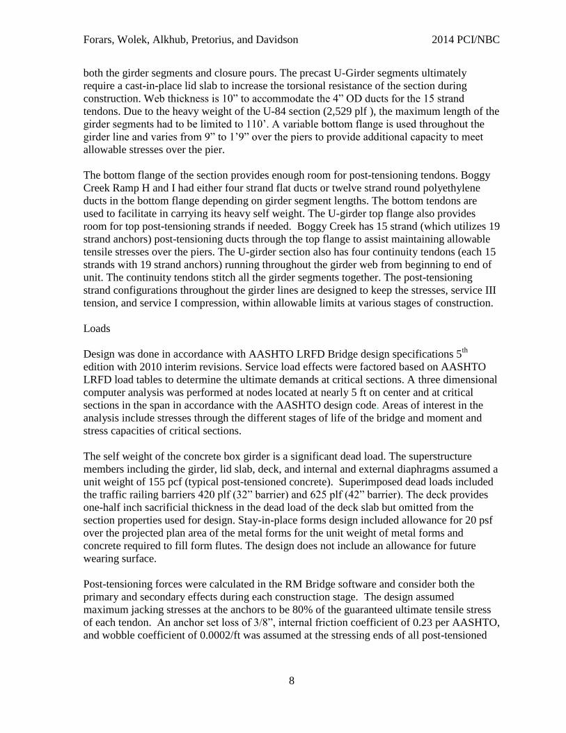
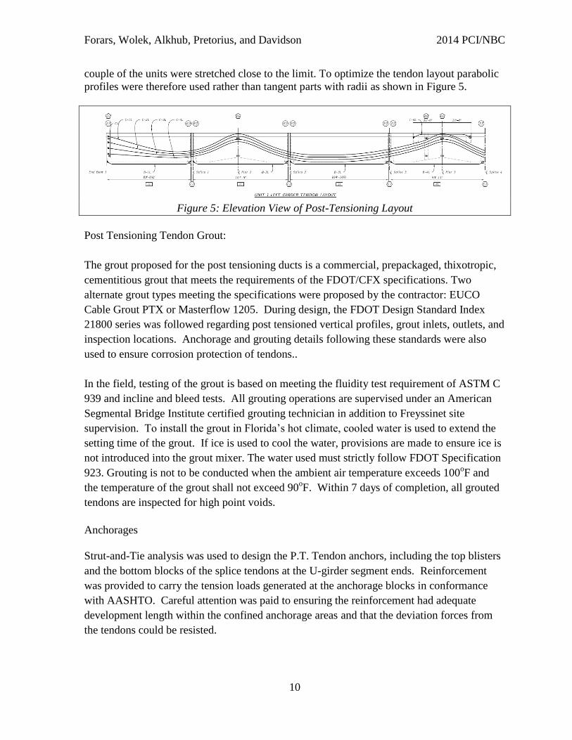
couple of the units were stretched close to the limit. To optimize the tendon layout parabolic
profiles were therefore used rather than tangent parts with radii as shown in Figure 5.
Figure 5: Elevation View of Post-Tensioning Layout
Post Tensioning Tendon Grout:
The grout proposed for the post tensioning ducts is a commercial, prepackaged, thixotropic,
cementitious grout that meets the requirements of the FDOT/CFX specifications. Two
alternate grout types meeting the specifications were proposed by the contractor: EUCO
Cable Grout PTX or Masterflow 1205. During design, the FDOT Design Standard Index
21800 series was followed regarding post tensioned vertical profiles, grout inlets, outlets, and
inspection locations. Anchorage and grouting details following these standards were also
used to ensure corrosion protection of tendons..
In the field, testing of the grout is based on meeting the fluidity test requirement of ASTM C
939 and incline and bleed tests. All grouting operations are supervised under an American
Segmental Bridge Institute certified grouting technician in addition to Freyssinet site
supervision. To install the grout in Florida’s hot climate, cooled water is used to extend the
setting time of the grout. If ice is used to cool the water, provisions are made to ensure ice is
not introduced into the grout mixer. The water used must strictly follow FDOT Specification
923. Grouting is not to be conducted when the ambient air temperature exceeds 100oF and
the temperature of the grout shall not exceed 90oF. Within 7 days of completion, all grouted
tendons are inspected for high point voids.
Anchorages
Strut-and-Tie analysis was used to design the P.T. Tendon anchors, including the top blisters
and the bottom blocks of the splice tendons at the U-girder segment ends. Reinforcement
was provided to carry the tension loads generated at the anchorage blocks in conformance
with AASHTO. Careful attention was paid to ensuring the reinforcement had adequate
development length within the confined anchorage areas and that the deviation forces from
the tendons could be resisted.
Forars, Wolek, Alkhub, Pretorius, and Davidson 2014 PCI/NBC
11
Diaphragms and Web Shear Transfer
Cast-in-place diaphragms are required at the ends of all units and at continuous sections over
piers. The diaphragms are critical for providing stability during construction and for load
transfer between the adjacent U-girders when the bridge is in service. They utilize continuous
P.T. Bars and mild steel reinforcement to accommodate significant bending, shear and
torsion demands. These demands were calculated using RM Bridge and the required
reinforcement and post-tensioning was designed and checked using the software XTRACT
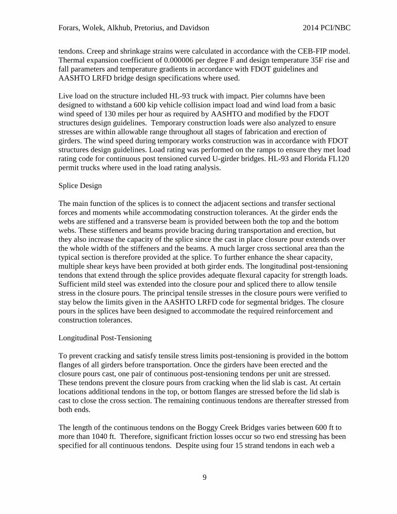
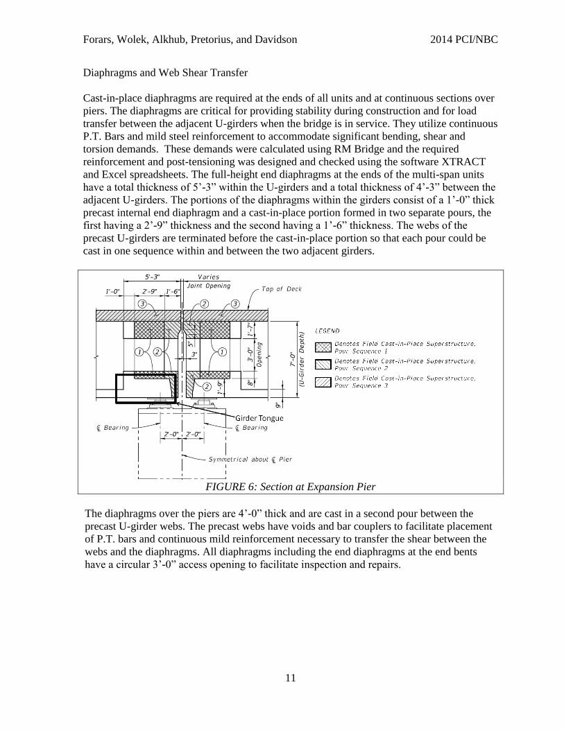
and Excel spreadsheets. The full-height end diaphragms at the ends of the multi-span units
have a total thickness of 5’-3” within the U-girders and a total thickness of 4’-3” between the
adjacent U-girders. The portions of the diaphragms within the girders consist of a 1’-0” thick
precast internal end diaphragm and a cast-in-place portion formed in two separate pours, the
first having a 2’-9” thickness and the second having a 1’-6” thickness. The webs of the
precast U-girders are terminated before the cast-in-place portion so that each pour could be
cast in one sequence within and between the two adjacent girders.
FIGURE 6: Section at Expansion Pier
The diaphragms over the piers are 4’-0” thick and are cast in a second pour between the
precast U-girder webs. The precast webs have voids and bar couplers to facilitate placement
of P.T. bars and continuous mild reinforcement necessary to transfer the shear between the
webs and the diaphragms. All diaphragms including the end diaphragms at the end bents
have a circular 3’-0” access opening to facilitate inspection and repairs.
Forars, Wolek, Alkhub, Pretorius, and Davidson 2014 PCI/NBC
12
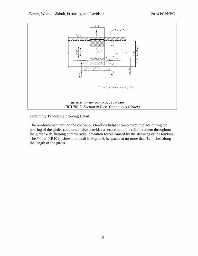
FIGURE 7: Section at Pier (Continuous Girder)
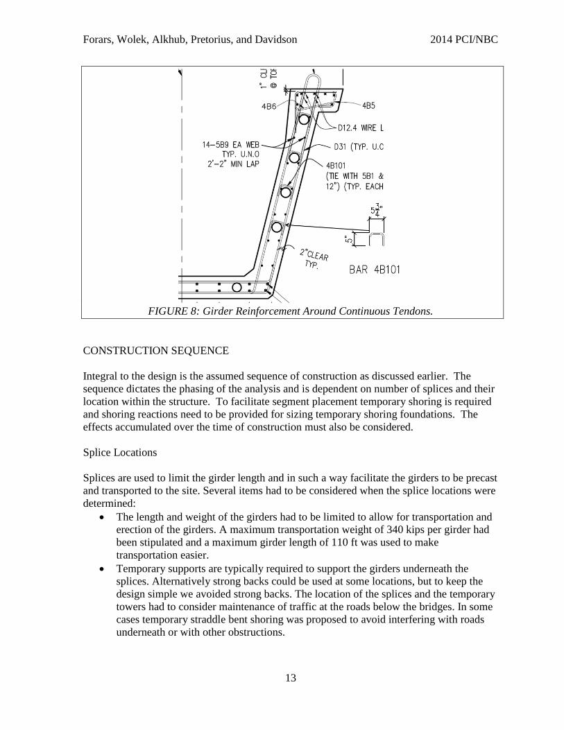
Continuity Tendon Reinforcing Detail
The reinforcement around the continuous tendons helps to keep them in place during the
pouring of the girder concrete. It also provides a secure tie to the reinforcement throughout
the girder web, helping control radial deviation forces caused by the stressing of the tendons.
The #4 bar (4B101), shown in detail in Figure 8, is spaced at no more than 12 inches along
the length of the girder.
Forars, Wolek, Alkhub, Pretorius, and Davidson 2014 PCI/NBC
13
FIGURE 8: Girder Reinforcement Around Continuous Tendons.
CONSTRUCTION SEQUENCE
Integral to the design is the assumed sequence of construction as discussed earlier. The
sequence dictates the phasing of the analysis and is dependent on number of splices and their
location within the structure. To facilitate segment placement temporary shoring is required
and shoring reactions need to be provided for sizing temporary shoring foundations. The
effects accumulated over the time of construction must also be considered.
Splice Locations
Splices are used to limit the girder length and in such a way facilitate the girders to be precast
and transported to the site. Several items had to be considered when the splice locations were
determined:
The length and weight of the girders had to be limited to allow for transportation and
erection of the girders. A maximum transportation weight of 340 kips per girder had
been stipulated and a maximum girder length of 110 ft was used to make
transportation easier.
Temporary supports are typically required to support the girders underneath the
splices. Alternatively strong backs could be used at some locations, but to keep the
design simple we avoided strong backs. The location of the splices and the temporary
towers had to consider maintenance of traffic at the roads below the bridges. In some
cases temporary straddle bent shoring was proposed to avoid interfering with roads
underneath or with other obstructions.
Forars, Wolek, Alkhub, Pretorius, and Davidson 2014 PCI/NBC
14
It is also important to consider structural implications when the splice locations are
determined. Post-tensioning tendons are provided to the individual girders to resist
stresses during transportation and erection. These tendons provide additional girder
capacity for positive moment between the splices, but since the tendons terminate
next to the splice the resistance is less at the splice. In addition, the allowable tensile
stress is reduced at the splices. Because the tensile resistance is less at the splices,
they were typically placed approximately at the inflection points of the deflected
girders, where the demand is the least. The splices must also satisfy the same limits
for principal stresses as segmental bridges. However, at the inflection points, the
shear force and consequently also the principal tensile stresses remain reasonable.
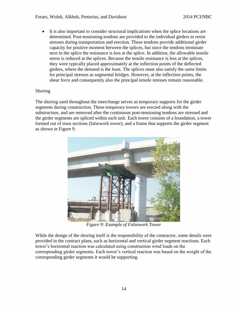
Shoring
The shoring used throughout the interchange serves as temporary supports for the girder
segments during construction. These temporary towers are erected along with the
substructure, and are removed after the continuous post-tensioning tendons are stressed and
the girder segments are spliced within each unit. Each tower consists of a foundation, a tower
formed out of truss sections (falsework tower), and a frame that supports the girder segment
as shown in Figure 9.
Figure 9: Example of Falsework Tower
While the design of the shoring itself is the responsibility of the contractor, some details were
provided in the contract plans, such as horizontal and vertical girder segment reactions. Each
tower’s horizontal reaction was calculated using construction wind loads on the
corresponding girder segments. Each tower’s vertical reaction was based on the weight of the
corresponding girder segments it would be supporting.
Forars, Wolek, Alkhub, Pretorius, and Davidson 2014 PCI/NBC
15
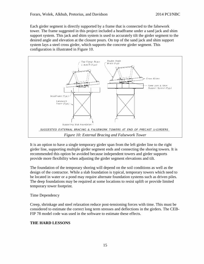
Each girder segment is directly supported by a frame that is connected to the falsework
tower. The frame suggested in this project included a headframe under a sand jack and shim
support system. This jack and shim system is used to accurately tilt the girder segment to the
desired angle and elevation at the closure pours. On top of the sand jack and shim support
system lays a steel cross girder, which supports the concrete girder segment. This
configuration is illustrated in Figure 10.
Figure 10: External Bracing and Falsework Tower
It is an option to have a single temporary girder span from the left girder line to the right
girder line, supporting multiple girder segment ends and connecting the shoring towers. It is
recommended this option be avoided because independent towers and girder supports
provide more flexibility when adjusting the girder segment elevations and tilt.
The foundation of the temporary shoring will depend on the soil conditions as well as the
design of the contractor. While a slab foundation is typical, temporary towers which need to
be located in water or a pond may require alternate foundation systems such as driven piles.
The deep foundations may be required at some locations to resist uplift or provide limited
temporary tower footprint.
Time Dependency
Creep, shrinkage and steel relaxation reduce post-tensioning forces with time. This must be
considered to estimate the correct long term stresses and deflections in the girders. The CEB-
FIP 78 model code was used in the software to estimate these effects.
THE HARD LESSONS
Forars, Wolek, Alkhub, Pretorius, and Davidson 2014 PCI/NBC
16
GEOMETRIC OPTIMIZATION
Simplifying the form set up was one goal of the original geometric design of the U-girders.
During design, throughout the spans the radii of each of the girders in each span were
matched, rather than having each girder follow its own independent radius that matched the
deck geometry. This cut down the number radii that would need to be formed, thus reducing
the number of form setups. However, based on the review by the contractor, the contractor’s
engineer requested to reduce the number of different radii even further. This was
accomplished by also keeping as many units as possible in adjacent spans the same. With the
relatively large radii, this did not have a significant impact on the overall bridge geometry.
Variations in the deck overhangs relative to the girders were changed by less than a few
inches. The location of the girders on the piers also had to be confirmed and also varied by
less than a few inches and had minimal impact to the cap and column demands. Minor
alignment adjustments between the longitudinal girder segments were accommodated within
the cast-in-place splices.
SPACE TO ACCOMMODATE JACK
At expansion ends, one of the important features of the girder segments are the tongues,
essentially a projection of the girder bottom flanges (See Figure 6). These tongues allow for
the girder segment to be supported while leaving room for jacking of the tendons. The initial
design of the girder used the tongue dimensions as recommended in the PCI Standards.
These dimensions assume that short stroke jacks and staged pulling of the tendons will be
utilized. However, the Post-Tensioning supplier selected by the contractor did not have a
short stroke jack that would fit in the specified gap. Therefore, the tongue length on the
segments was adjusted by six inches to allow an additional one foot of gap and thereby
accommodate the proposed jacking system. It is recommended that the PCI Standards be
updated with this additional 6” tongue length.
CLOSURE POUR CONCRETE
For the initial design, closure pour concrete between the segments with strength equal to the
girder segments (8500 psi) was selected. This concrete is not readily available by typical
concrete suppliers and would have had to come from the pre-cast yard. The contractor
relocated several splices to facilitate their construction approach; and, therefore, needed to
revisit the splice designs. The main demand governing the need for the closure pour concrete
strength was tension. The relocated splices initially increased the tension stress. However,
with minor adjustment to the post-tensioning path, the contractor was able to reduce tension
demand on the splices enough to allow lower strength (5500 psi) concrete. This gave the
contractor more alternatives for suppliers and reduced his costs.
DIAPHRAGM POST-TENSIONING
Due to the relatively long spans and curvature, shear and torsion at the ends of the girders is
significant. In order to transfer these forces, transverse post-tensioning was required in the
Forars, Wolek, Alkhub, Pretorius, and Davidson 2014 PCI/NBC
17
diaphragms at the girder ends to develop shear friction with the girder webs. In the original
design, transverse PT Bars were selected to develop the clamping force. The PT Bars were
chosen in part because of the short distance between anchorages. For short PT systems,
anchor set loss can cause a disproportional reduction in effective PT. Bar anchorages have
less anchor set loss than strand anchorages and were therefore selected in the original design.
However, the project PT supplier preferred to use strand due to the potential for differential
alignment of the ducts penetrating the webs of the adjacent girders. To increase the tolerance
for placement of the PT, more flexible strands were preferred. Any increase in PT area was
offset by the increased placement tolerance.
TENSIONING SEQUENCE
In the original design the top tendons were stressed after the closure pours had been cast and
the first pair of continuous tendons had been stressed. It was more difficult to meet the stress
limits in the bottom fibers than in the top fibers so a benefit of stressing the top tendons after
the girder had been made continuous is that they generated favorable secondary moments for
the bottom fiber stresses.
After the construction contract had been awarded the contractor requested the top tendons to
be stressed in the casting yard to avoid inconvenient stressing operations on site. The
contractor had independently requested the continuous tendons to be brought down below the
top bar of the bottom slab at certain locations to provide more balanced deflections between
spans and therefore less required build up. This change allowed the revised tendon layout to
provide redundant capacity for the bottom fiber stresses that compensated for the loss of
beneficial secondary moments resulting from stressing the top tendons on statically
determinate girder sections rather than on full length continuous girder units. It was also
found to be acceptable since the girder could be lifted and transported to the site without
exceeding the allowable stresses.
LIFTING FROM THE PRECAST BED
One of the main advantages of the precast, post tensioned girder is the decrease in cost and
construction time by transporting the girders in long segments rather than casting the
concrete on site and waiting for the concrete to harden. In order to achieve this, the stresses
of the girder and reinforcement must be checked during multiple stages of fabrication and
construction.
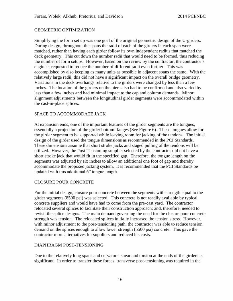
The first stage of girder fabrication consists of casting the U-Girder in the concrete forms.
These forms are curved beds (shown in Figure 11), filled with the required reinforcement and
post-tensioning ducts.
Forars, Wolek, Alkhub, Pretorius, and Davidson 2014 PCI/NBC
18
Figure 11: U-Girder External Form
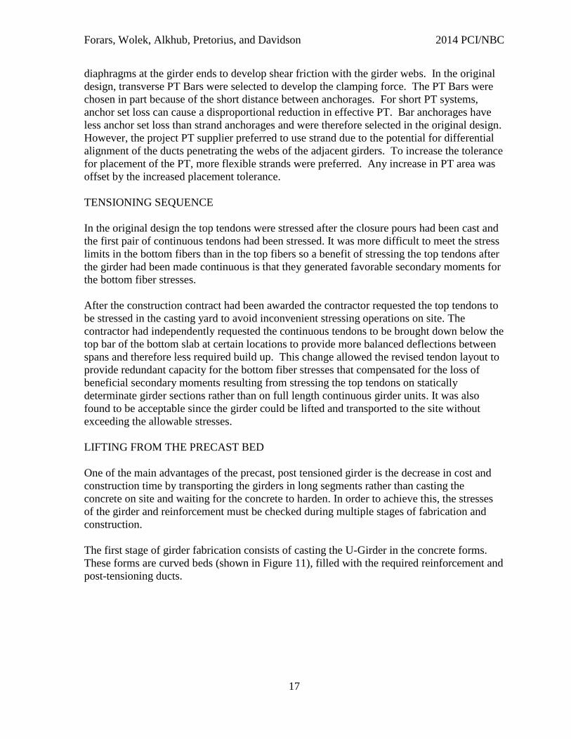
The girder formwork consists of multiple pieces. Figure 11 illustrates the outer perimeter of
the girder and Figure 12 shows the pieces that are lifted into the casting bed, providing the
inner perimeter of the girder.
Figure 12: U-Girder Interior Form Sections
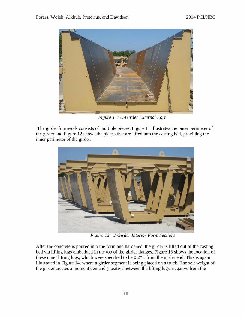
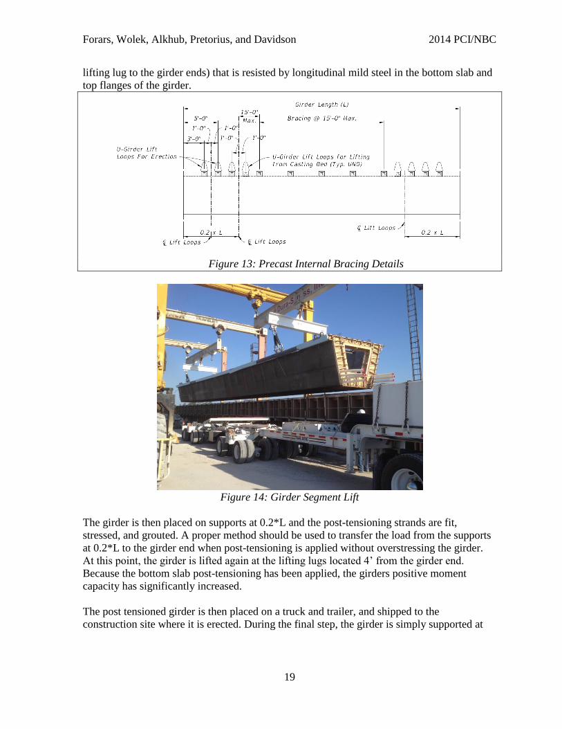
After the concrete is poured into the form and hardened, the girder is lifted out of the casting
bed via lifting lugs embedded in the top of the girder flanges. Figure 13 shows the location of
these inner lifting lugs, which were specified to be 0.2*L from the girder end. This is again
illustrated in Figure 14, where a girder segment is being placed on a truck. The self weight of
the girder creates a moment demand (positive between the lifting lugs, negative from the
Forars, Wolek, Alkhub, Pretorius, and Davidson 2014 PCI/NBC
19
lifting lug to the girder ends) that is resisted by longitudinal mild steel in the bottom slab and
top flanges of the girder.
Figure 13: Precast Internal Bracing Details
Figure 14: Girder Segment Lift
The girder is then placed on supports at 0.2*L and the post-tensioning strands are fit,
stressed, and grouted. A proper method should be used to transfer the load from the supports
at 0.2*L to the girder end when post-tensioning is applied without overstressing the girder.
At this point, the girder is lifted again at the lifting lugs located 4’ from the girder end.
Because the bottom slab post-tensioning has been applied, the girders positive moment
capacity has significantly increased.
The post tensioned girder is then placed on a truck and trailer, and shipped to the
construction site where it is erected. During the final step, the girder is simply supported at
Forars, Wolek, Alkhub, Pretorius, and Davidson 2014 PCI/NBC
20
both ends on the temporary towers, where it is subjected to the maximum positive moment
before being spliced with the rest of the girder line.
The temporary stress calculations and procedure exist to ensure the girder has the strength to
endure all of the stresses it will undergo from the casting bed to the shoring towers. Both
positive and negative moments were checked at every stage of the process. These
calculations included a SAP model and excel calculations that took into account every
possible detail for each girder. Along with the girder stress checks, the temporary stress
calculations provided the girder weight and lifting eccentricity on the spreader bar for each
girder segment. Both of these values are represented in tables in the contract plans.
While the contract plans provide suggested lifting points and bottom slab post-tensioning
configurations, the contractor is responsible to ensure the girder is not overstressed from the
time it is cast until the time it is supported on the temporary towers.
The contractor proposed moving the inner lifting lugs to 0.15*L from the girder ends instead
of 0.2*L. They also added additional longitudinal mild steel as reinforcement in the top of
the webs at the girder ends for additional negative moment capacity. As mentioned
previously, the contractor also proposed stressing the top flange post-tensioning while the
girder was still in the casting yard, and not after erection as proposed in the contract plans.
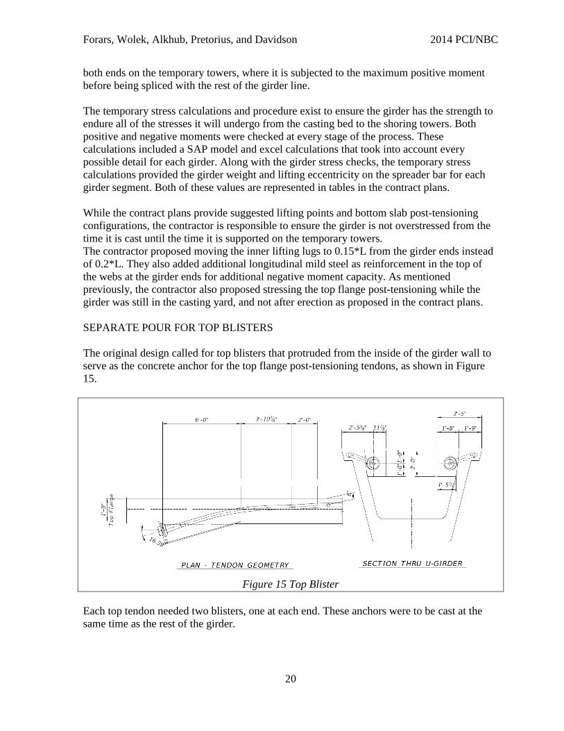
SEPARATE POUR FOR TOP BLISTERS
The original design called for top blisters that protruded from the inside of the girder wall to
serve as the concrete anchor for the top flange post-tensioning tendons, as shown in Figure
15.
Figure 15 Top Blister
Each top tendon needed two blisters, one at each end. These anchors were to be cast at the
same time as the rest of the girder.
Forars, Wolek, Alkhub, Pretorius, and Davidson 2014 PCI/NBC
21
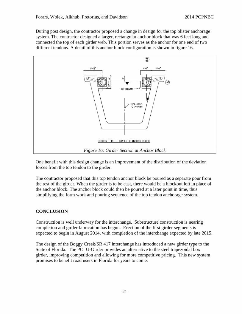
During post design, the contractor proposed a change in design for the top blister anchorage
system. The contractor designed a larger, rectangular anchor block that was 6 feet long and
connected the top of each girder web. This portion serves as the anchor for one end of two
different tendons. A detail of this anchor block configuration is shown in figure 16.
Figure 16: Girder Section at Anchor Block
One benefit with this design change is an improvement of the distribution of the deviation
forces from the top tendon to the girder.
The contractor proposed that this top tendon anchor block be poured as a separate pour from
the rest of the girder. When the girder is to be cast, there would be a blockout left in place of
the anchor block. The anchor block could then be poured at a later point in time, thus
simplifying the form work and pouring sequence of the top tendon anchorage system.
CONCLUSION
Construction is well underway for the interchange. Substructure construction is nearing
completion and girder fabrication has begun. Erection of the first girder segments is
expected to begin in August 2014, with completion of the interchange expected by late 2015.
The design of the Boggy Creek/SR 417 interchange has introduced a new girder type to the
State of Florida. The PCI U-Girder provides an alternative to the steel trapezoidal box
girder, improving competition and allowing for more competitive pricing. This new system
promises to benefit road users in Florida for years to come.