Embed Size (px)
Citation preview

534-450-MU2 Rev. 2
XGPLab NEUROPHYSIOLOGY AND SLEEP
SOFTWARE
User’s Manual
BITMED Clinical Manual XGPLAB

534-450-MU2 Rev. 2
Version: XGPLAB-534-450-MU2 Rev. 2
All rights reserved.
SIBEL S.A.
Rosellón, 500 bajos
08026 Barcelona
Spain
Tel: 93 436 00 08 FAX: 93 436 16 11
WEB: www.sibelmed.com
e-mail: [email protected]
AFTER-SALES SERVICE
Contact SIBEL S.A. at the above address or
MEDITEL Ingeniería Médica S.L. Pablo Iglesias, 28
E-50018 ZARAGOZA (Spain)
Tel: 976 466 009 FAX: 976 466 132
e-mail: [email protected]
WARNING CONCERNING COPYRIGHT:
No part whatsoever of this publication may be reproduced, transmitted, transcribed, stored in a back-up system nor translated into any language or computer language in any form or by any means, whether electronic, mechanical, optical, chemical, manual or any other type, without the express written consent of SIBEL S.A..
DISCLAIMER
SIBEL S.A. will only be responsible for the safety, reliability, and operation of this unit if:
• The site where the equipment is installed or used meets the requirements relating to the IEC electrical installation, as well as all other applicable regulations.
• Repairs, inspections or modifications, whether within or outside the guarantee period, are carried out by technical personnel from MEDITEL Ingeniería Médica S.L. or SIBEL S.A.
• The unit is used by qualified personnel in accordance with the recommendations in this User’s Manual.
Trademarks
Sibel S.A. is the manufacturer of the systems Bitmed eXim Apnea, Bitmed eXim Pro, Bitmed eXea PSG Series 3, Bitmed eXea PSG Series 4, Bitmed eXea PSG Series 5, Bitmed eXea EEG, Bitmed eXea Ultra and of XGPLab software.
Meditel Ingeniería Médica S.L. is the distributor of BITMED trademark units.

534-450-MU2 Rev. 2
PRODUCT IN COMPLIANCE WITH MEDICAL DEVICE DIRECTIVE 93/42/EEC (CLASS IIa).
Thank you for choosing this product. The XGPLab software has been designed and produced at the highest quality.
The applications of the XGPLab software and its related software will open up a whole world of possibilities in the study of sleep and electroencephalography thanks to its features and ease of operation.
Should you have any suggestions for possible improvement of this product, we would be grateful if you would send these to the Customer Service Dept., at the following address:
Customer Service Department Meditel Ingeniería Médica, S.L.
Pablo Iglesias, 28 E-50018 ZARAGOZA (Spain)
Tel. 976 466 009 Fax 976 466 132 e-mail: [email protected]
Web: http://www.bitmed.com
534-450-MU2 Rev. 2
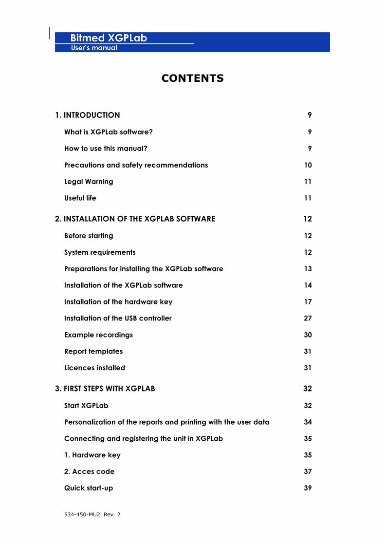
CONTENTS
1. INTRODUCTION 9
What is XGPLab software? 9
How to use this manual? 9
Precautions and safety recommendations 10
Legal Warning 11
Useful life 11
2. INSTALLATION OF THE XGPLAB SOFTWARE 12
Before starting 12
System requirements 12
Preparations for installing the XGPLab software 13
Installation of the XGPLab software 14
Installation of the hardware key 17
Installation of the USB controller 27
Example recordings 30
Report templates 31
Licences installed 31
3. FIRST STEPS WITH XGPLAB 32
Start XGPLab 32
Personalization of the reports and printing with the user data 34
Connecting and registering the unit in XGPLab 35
1. Hardware key 35
2. Acces code 37
Quick start-up 39

534-450-MU2 Rev. 2
4. THE WORK AREA OF XGPLAB 44
Time bar 44
Tool bar 45
General tool bar 45
Sleep tool bar 45
EEG tool bar 46
Status bar 46
Wave display 47
Stages and events display 48
Synchronized digital video window 48
5. MANAGEMENT OF RECORDINGS 50
Database 50
Opening a recording 57
Saving a recording 57
Sending a recording or a report by e-mail 57
Exporting the recording 58
Printing the recording 60
Preview of the printout of a recording period 61
6. MAKING A RECORDING 62
Types of studies 62
Recording in real time 62
Recording with photic stimulator (manual control) 73
Recording with photic stimulator (software control) 75
Recording in residential mode 78
Modifying the sampling frequency of the channels 86

534-450-MU2 Rev. 2
Changing the real-time representation mode 88
Using the chronometer in real-time recordings 89
Starting/stopping the chronometer 90
7 REVISING A RECORDING 91
Adjust the screen time 91
Modifying the time reference 95
Moving through the recording 96
Notes in the recording 98
Adjusting the amplitudes of the channels 100
Adjusting size of channels 103
Modifying the viewing order of the channels 104
Modifying the name of the channels in the tracing 105
Hiding or showing separation between channels 106
Adding and removing channels to wave displays 107
Configuring the signal to each input channel 110
Cambiar los filtros software 111
Creating derivations of EEG/EOG 112
Changing colour for tracing of signals 121
Showing values for a channel 122
Cursor with numerical values 124
Predetermined configurations 125
Event types 130
Marking of events 134
Sleep stages 153
Event summary panel 158
Playing back the recording 159
534-450-MU2 Rev. 2
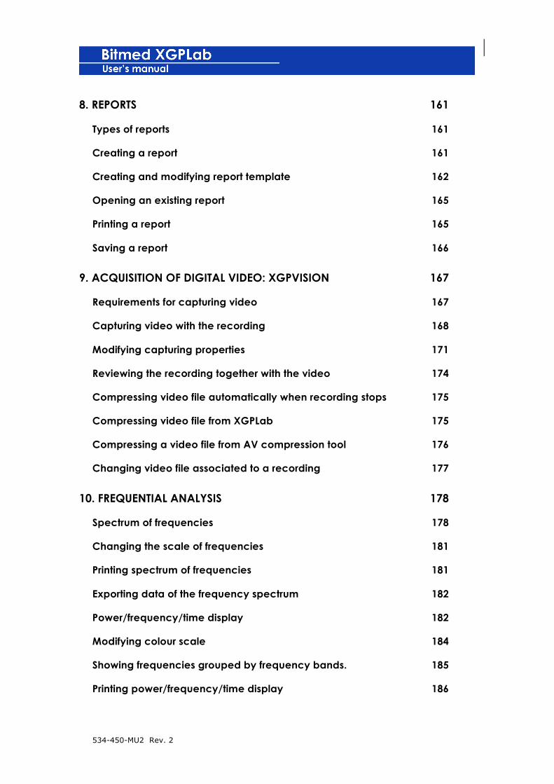
8. REPORTS 161
Types of reports 161
Creating a report 161
Creating and modifying report template 162
Opening an existing report 165
Printing a report 165
Saving a report 166
9. ACQUISITION OF DIGITAL VIDEO: XGPVISION 167
Requirements for capturing video 167
Capturing video with the recording 168
Modifying capturing properties 171
Reviewing the recording together with the video 174
Compressing video file automatically when recording stops 175
Compressing video file from XGPLab 175
Compressing a video file from AV compression tool 176
Changing video file associated to a recording 177
10. FREQUENTIAL ANALYSIS 178
Spectrum of frequencies 178
Changing the scale of frequencies 181
Printing spectrum of frequencies 181
Exporting data of the frequency spectrum 182
Power/frequency/time display 182
Modifying colour scale 184
Showing frequencies grouped by frequency bands. 185
Printing power/frequency/time display 186

534-450-MU2 Rev. 2
1. INTRODUCTION
What is XGPLab software?
XGPLab software is the bridge link between the units for sleep study
and EEG of Meditel Medical Engineering (Bitmed eXim Apnea, Bitmed
eXim Pro, Bitmed eXea PSG Series 3, Bitmed eXea PSG Series 4,
Bitmed eXea PSG 5, Bitmed eXea EEG, Bitmed eXea Ultra) and you
as the user through a PC.
XGPLab allows for the revision and analysis of the data collected in
residential mode or in real time by the Bitmed eXim or Bitmed eXea
units.
The units of the Bitmed eXim and Bitmed eXea families are delivered
with all their accessories and with the XGPLab analysis software. This
manual describes the XGPLab software.
! Please read this manual carefully before using the
XGPLab software, especially the sections carrying an
exclamation mark.
How to use this manual?
The XGPLab software has two modes of operation, depending on the
purpose for which it is to be used: study of sleep disorders, or
electroencephalography (we will refer to these two modes, from now
on, as sleep mode and EEG mode). As will be explained later, the
user can start the program in either mode.
534-450-MU2 Rev. 2
The manual includes aspects of the program that are common to both
work modes, as well as specific questions on each of them. To
distinguish between the descriptions for both work modes, the
following symbols are used in the manual:
Text referring to aspects of sleep mode
Texts referring to aspects of EEG mode
Precautions and safety recommendations
For the correct operation of the system, the XGPLab software must be
used with Bitmed eXim or Bitmed eXea devices. Please read the
user’s manual for your unit before using it.
Use the unit according to the instructions included in your manual.
The derived effects of the use given to this software and the device to
which it is connected are not covered.
The manufacturer is responsible for the safety, reliability and
functionality of the units only if:
• Modifications or repairs are carried out by the manufacturer
or an Authorized Assistance Centre.
• The system is used according to the instructions for use.
• In order to comply with the Medical Device Directive
93/42/EEC and for safety and reliability reasons, make sure
that the unit and its software are handled by personnel that

534-450-MU2 Rev. 2
are appropriately trained in the purposes for which they are to
be used.
Legal Warning
None of the results supplied by the Automatic Analyses contained in
the XGPLab must be used as a single criterion for medical diagnosis
or treatment. This information should not be considered complete,
nor should it be relied upon to prescribe a treatment for any
individual. The user should consider the results of the Automatic
Analyses generated by the XGPLab as non-exhaustive and these
should always be supervised and checked by medical personnel with
the appropriate training in this respect.
IN NO CASE WILL SIBEL S.A. BE HELD RESPONSIBLE FOR ANY LOSS, DAMAGE
OR EXPENSE DERIVING FROM IMPROPER USE OF THE DEVICE, OF THE
SOFTWARE OR COMPUTER PROGRAMS (OPERATING SYSTEMS); OR FOR
BREAKDOWNS OR ACCIDENTS OF OTHER COMPUTER EQUIPMENT.
Useful life 7 years

534-450-MU2 Rev. 2
2. INSTALLATION OF THE XGPLAB SOFTWARE
Before starting
Examine the system requirements shown below to ensure that the
XGPLab software can be run on your system.
System requirements
The computer requirements are determined by the fact that the units
must transmit the signals acquired from the PC, while the PC must
represent this information in real time. Thus, the better the
hardware, the more efficient the operation of the system will be as a
result.
The technical requirements of the computer are specified as follows:
Required Recommended
Operating System Windows XP, Windows Vista, Windows 7
32/64bits
Windows XP, Windows Vista, Windows 7
32/64bits
Processor Pentium 4, Athlon XP, Athlon 64
Intel o AMD Dual Core, Core 2, Athlon x2,
Phenom x2, … or greater
Memory 512 Mb (Windows XP) 1Gb (Windows Vista, 7)
2 Gb
Space available on
hard disk
Depending on features purchased and tests that you wish to store in the
database
Several Gb if it is wished
to acquire synchronized
digital video
USB 2 USB 1.1 ports free (one
for the connection with
the unit and another for
the hardware key)
2 USB 1.1 ports free (one
for the connection with
the unit and another for
the hardware key)
534-450-MU2 Rev. 2
Screen resolution 800 x 600 1024 x 768 or greater
Photic stimulator
connection
Free serial port Free serial port
Synchronized digital
video capture
PCI Xpress slot free (desktop
computers)
Xpress Card slot free (laptop
computers)
PCI Xpress slot free (desktop
computers)
Xpress Card slot free (laptop
computers)
Preparations for installing the XGPLab software
Observe the type of distribution of XGPLab software you have and
carry out the corresponding procedure to prepare the files for
installation.
If you have downloaded a copy of the XGPLab software from the
Meditel Medical Engineering Website, have the route of the file on
hand so that it can be run later on. At www.bitmed.com you will find
the latest available versions of XGPLab.
If you have a copy of the XGPLab software on CD-ROM, insert the CD
in the computer’s CD-ROM compartment.
If you have inserted a CD-ROM, the installation of XGPLab should
start automatically. If you wish to install the XGPLab software, go to
the XGPLab software installation section in point 3. If the installation
does not begin or if you are going to install the XGPLab software from
a file downloaded from www.bitmed.com, continue in the XGPLab
software installation section.

534-450-MU2 Rev. 2
Installation of the XGPLab software
We recommend that you close all applications that you are running
on the system before starting with the installation. This will reduce
the possibility of a software conflict occurring that might affect the
installation.
To install the XGPLab software, proceed as indicated below:
1. Check to make sure that you have enough permits in the
system to install controllers and applications (system
administrator permits). This is an important question in
computers with Windows Vista (Home Premium o Business).
2. Select Run in the Start menu of the Windows task bar. The
dialog box Run will appear.
3. Write X:\setup.exe in the text box and click on Accept. The X
represents the letter of the CD-ROM compartment or the access
route to the folder that contains the installation file. To locate
the correct files in the hard disk or on the CD-ROM, click on
Examine.
4. The installation program will immediately show the first panel
of the assistant. Click on Next> to continue.

534-450-MU2 Rev. 2
5. The next panel of the assistant allows you to modify the folder
where the program files will be copied. If you wish to modify
the folder suggested by default, click on Examine. When it has
finished, click on Next>.

534-450-MU2 Rev. 2
6. Select the elements you wish to install on the next screen. The
element XGPLab Program must always be installed. The rest of
the elements are accessories (for instance, perhaps you only
wish to install the example corresponding to your type of unit
or the video uses if you have acquired the XGPVision licence).
Click on next.
7. The installation will copy the appropriate files. Depending on
the options installed, the installation may ask you to restart the
computer. Select Yes, I wish to restart the unit now and Click
on Finish to restart Windows.
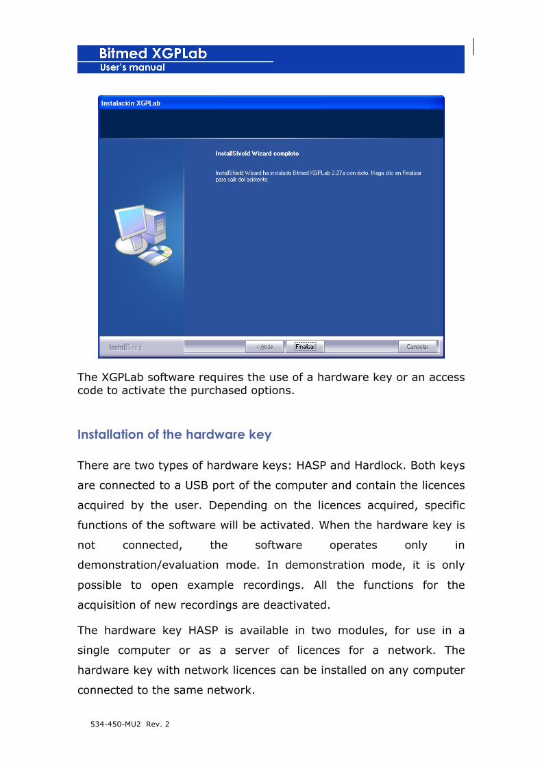
534-450-MU2 Rev. 2
The XGPLab software requires the use of a hardware key or an access code to activate the purchased options.
Installation of the hardware key
There are two types of hardware keys: HASP and Hardlock. Both keys
are connected to a USB port of the computer and contain the licences
acquired by the user. Depending on the licences acquired, specific
functions of the software will be activated. When the hardware key is
not connected, the software operates only in
demonstration/evaluation mode. In demonstration mode, it is only
possible to open example recordings. All the functions for the
acquisition of new recordings are deactivated.
The hardware key HASP is available in two modules, for use in a
single computer or as a server of licences for a network. The
hardware key with network licences can be installed on any computer
connected to the same network.
534-450-MU2 Rev. 2
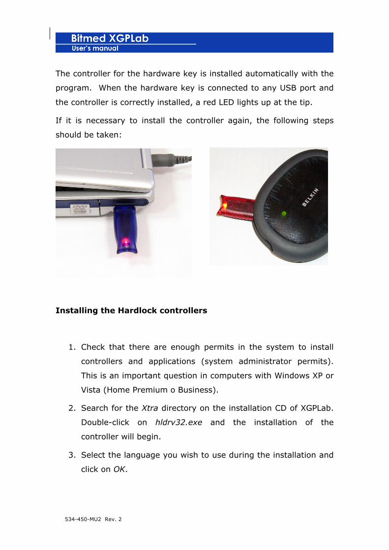
The controller for the hardware key is installed automatically with the
program. When the hardware key is connected to any USB port and
the controller is correctly installed, a red LED lights up at the tip.
If it is necessary to install the controller again, the following steps
should be taken:
Installing the Hardlock controllers
1. Check that there are enough permits in the system to install
controllers and applications (system administrator permits).
This is an important question in computers with Windows XP or
Vista (Home Premium o Business).
2. Search for the Xtra directory on the installation CD of XGPLab.
Double-click on hldrv32.exe and the installation of the
controller will begin.
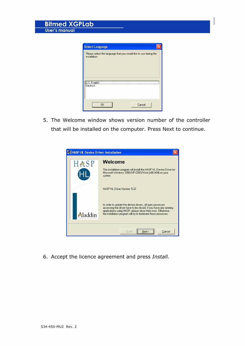
3. Select the language you wish to use during the installation and
click on OK.

534-450-MU2 Rev. 2
4. The greeting window shows the version of each file that is to
be installed with the controller. Click on Next to continue.
5. Once the files have been copied, click on to finish the
installation process.

534-450-MU2 Rev. 2
Installing the HASP controllers (single licence or network
client licence)
1. If you have acquired a single licence or a network client licence
and you want to install the HASP controllers in a computer not
connected physically to the HASP hardware key, follow the next
stops. Otherwise, read the next section.
2. Check that you have administration Rights on the computer for
installing controllers and applications. This is important in
computers working with Windows XP or Vista (Home Premium
o Business).
3. Search for the Xtra folder in the XGPLab installation CD.
Double-click the HASPUserSetup.exe file for starting the
controller installation.
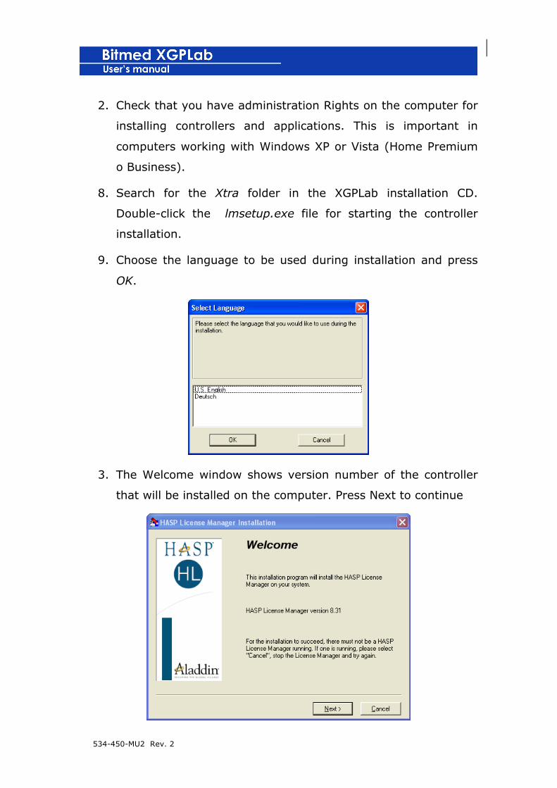
4. Choose the language to be used during installation and press
OK.
534-450-MU2 Rev. 2
5. The Welcome window shows version number of the controller
that will be installed on the computer. Press Next to continue.
6. Accept the licence agreement and press Install.

534-450-MU2 Rev. 2
7. After all files have been successfuly installed, press Finish.
Installing the HASP controllers (network licence Server)
1. The following steps indicate how to install the HASP controller
and the network licence Server onto the system where the
HASP network key is connected.
534-450-MU2 Rev. 2
2. Check that you have administration Rights on the computer for
installing controllers and applications. This is important in
computers working with Windows XP or Vista (Home Premium
o Business).
8. Search for the Xtra folder in the XGPLab installation CD.
Double-click the lmsetup.exe file for starting the controller
installation.
9. Choose the language to be used during installation and press
OK.
3. The Welcome window shows version number of the controller
that will be installed on the computer. Press Next to continue

534-450-MU2 Rev. 2
4. Accept the licence agreement and press Install.
5. In the following Windows, select the Service (nhservice.exe)
otion and press Next.
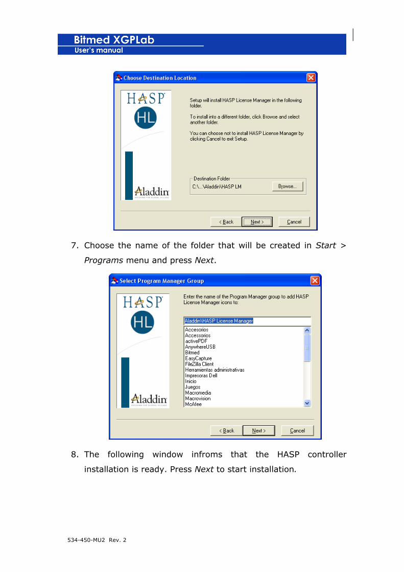
6. Choose the destination folder where the application will be
installed and press Next.
534-450-MU2 Rev. 2
7. Choose the name of the folder that will be created in Start >
Programs menu and press Next.
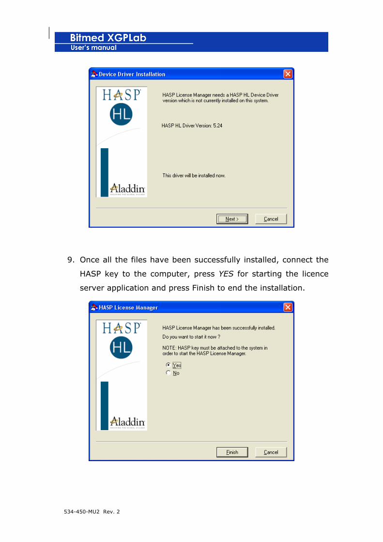
8. The following window infroms that the HASP controller
installation is ready. Press Next to start installation.
534-450-MU2 Rev. 2
9. Once all the files have been successfully installed, connect the
HASP key to the computer, press YES for starting the licence
server application and press Finish to end the installation.
534-450-MU2 Rev. 2
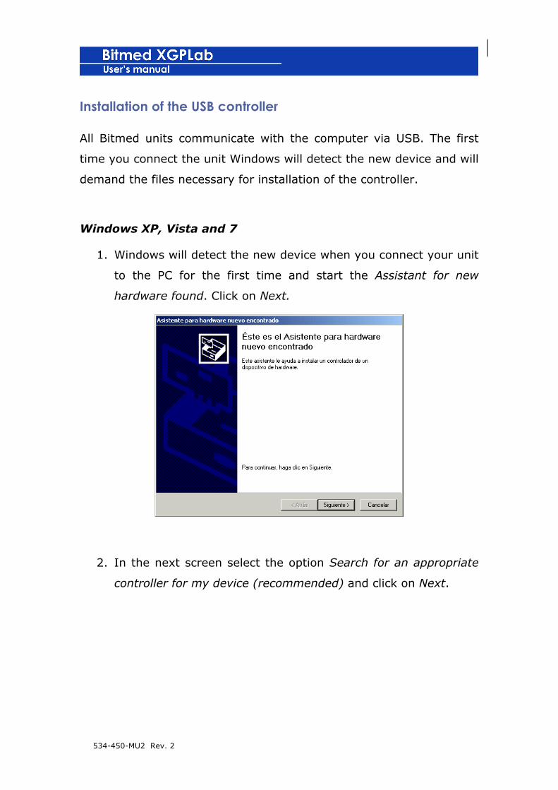
Installation of the USB controller
All Bitmed units communicate with the computer via USB. The first
time you connect the unit Windows will detect the new device and will
demand the files necessary for installation of the controller.
Windows XP, Vista and 7
1. Windows will detect the new device when you connect your unit
to the PC for the first time and start the Assistant for new
hardware found. Click on Next.
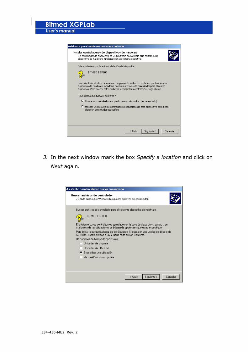
2. In the next screen select the option Search for an appropriate
controller for my device (recommended) and click on Next.
534-450-MU2 Rev. 2
3. In the next window mark the box Specify a location and click on
Next again.
534-450-MU2 Rev. 2
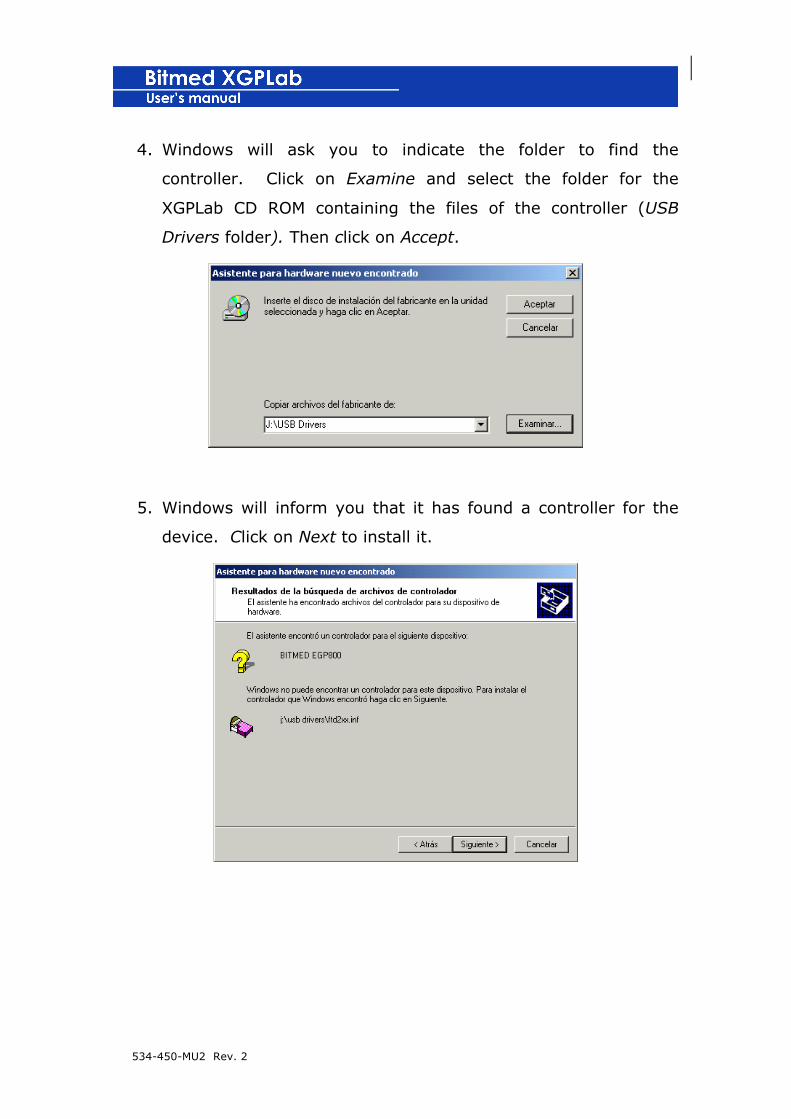
4. Windows will ask you to indicate the folder to find the
controller. Click on Examine and select the folder for the
XGPLab CD ROM containing the files of the controller (USB
Drivers folder). Then click on Accept.
5. Windows will inform you that it has found a controller for the
device. Click on Next to install it.

534-450-MU2 Rev. 2
6. Once the controller is installed, click on Finish to complete the
process.
Example recordings
Together with XGPLab a series of example recordings are copied to
the hard disk of the computer, made with different units of the
Bitmed range.
To install them, you only have to select the examples you wish to
copy in the installation options of XGPLab.
The example recordings can be found in the folder Examples of the
folder where the program has been installed (e.g. C:/Program
files/Bitmed/XGPLab_.__/Examples).
534-450-MU2 Rev. 2
Report templates
The XGPLab installation program automatically copies to the hard disk
a series of report templates which are used to generate the reports
acquired and analyzed with the program.
These templates are personalizable and are found in the folder
Templates of the folder where the XGPLab is installed (e.g.
C:/Program files/Bitmed/XGPLab2.26/Templates). The user can also
create new templates, which will be available in the program only by
copying them to the Templates folder.
Consult the chapter devoted to the generation of reports for further
details concerning the report templates.
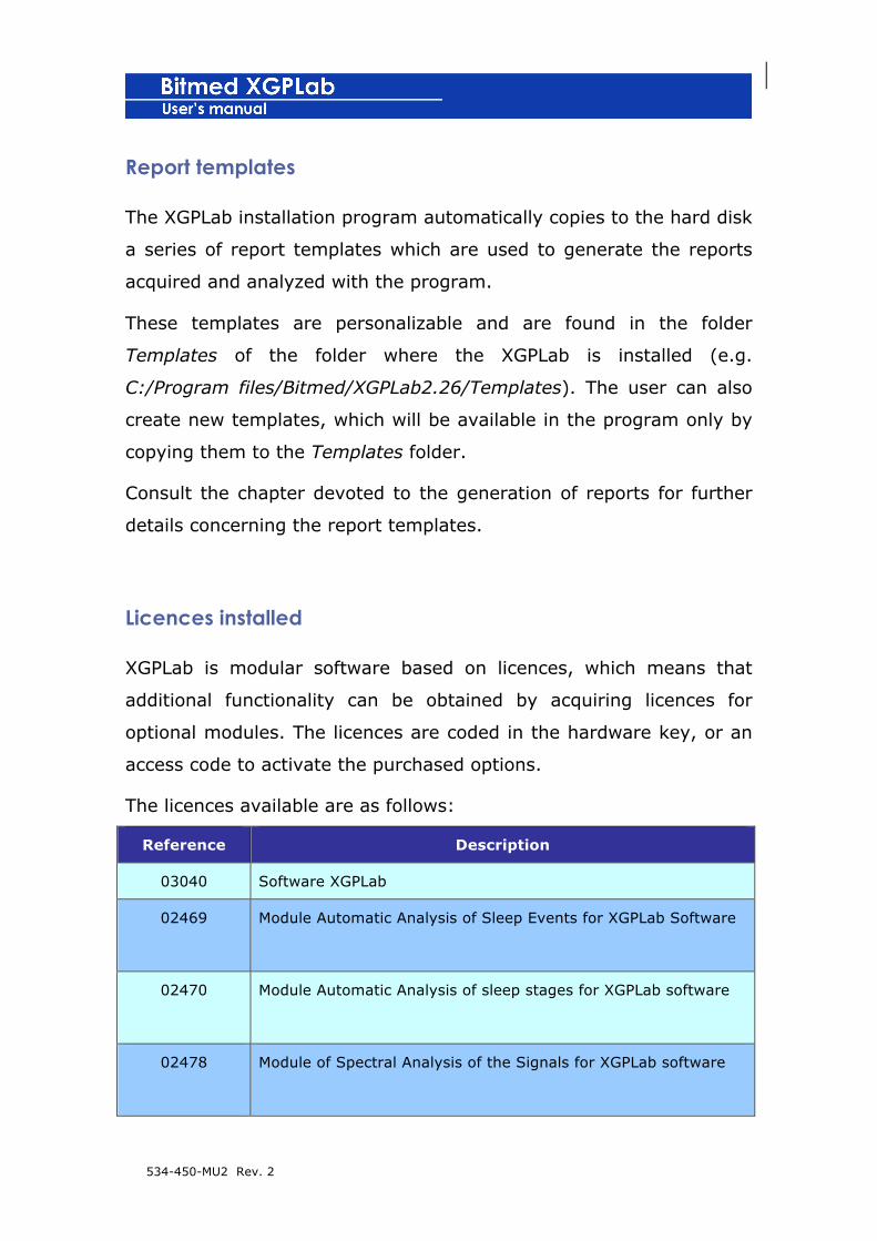
Licences installed
XGPLab is modular software based on licences, which means that
additional functionality can be obtained by acquiring licences for
optional modules. The licences are coded in the hardware key, or an
access code to activate the purchased options.
The licences available are as follows:
Reference Description
03040 Software XGPLab
02469
Module Automatic Analysis of Sleep Events for XGPLab Software
02470
Module Automatic Analysis of sleep stages for XGPLab software
02478
Module of Spectral Analysis of the Signals for XGPLab software
534-450-MU2 Rev. 2
02480
Module of Brain Mapping for XGPLab software
02481 Module of Spike Detection for XGPLab software
02508 Module XGPVision software
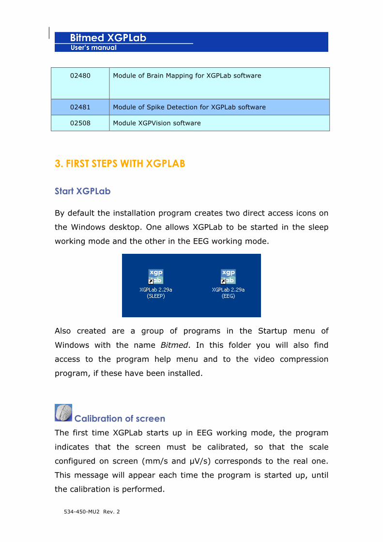
3. FIRST STEPS WITH XGPLAB
Start XGPLab
By default the installation program creates two direct access icons on
the Windows desktop. One allows XGPLab to be started in the sleep
working mode and the other in the EEG working mode.
Also created are a group of programs in the Startup menu of
Windows with the name Bitmed. In this folder you will also find
access to the program help menu and to the video compression
program, if these have been installed.
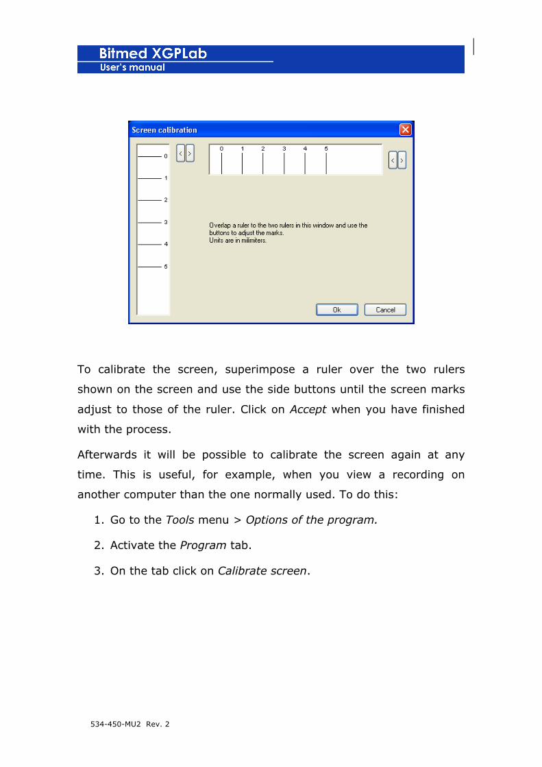
Calibration of screen
The first time XGPLab starts up in EEG working mode, the program
indicates that the screen must be calibrated, so that the scale
configured on screen (mm/s and µV/s) corresponds to the real one.
This message will appear each time the program is started up, until
the calibration is performed.
534-450-MU2 Rev. 2
To calibrate the screen, superimpose a ruler over the two rulers
shown on the screen and use the side buttons until the screen marks
adjust to those of the ruler. Click on Accept when you have finished
with the process.
Afterwards it will be possible to calibrate the screen again at any
time. This is useful, for example, when you view a recording on
another computer than the one normally used. To do this:
1. Go to the Tools menu > Options of the program.
2. Activate the Program tab.
3. On the tab click on Calibrate screen.
534-450-MU2 Rev. 2
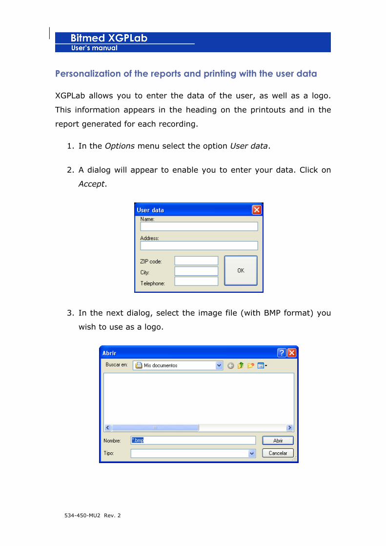
Personalization of the reports and printing with the user data
XGPLab allows you to enter the data of the user, as well as a logo.
This information appears in the heading on the printouts and in the
report generated for each recording.
1. In the Options menu select the option User data.
2. A dialog will appear to enable you to enter your data. Click on
Accept.
3. In the next dialog, select the image file (with BMP format) you
wish to use as a logo.

534-450-MU2 Rev. 2
Connecting and registering the unit in XGPLab
Before starting to use the software with one of the Bitmed units, it is
necessary to register the unit in XGPLab. Having several different
units registered is no problem, as XGPLab will ask you which one you
wish to use when you make a new recording, download the memory,
etc.
1. Hardware key
Follow these instructions in order to register your Bitmed device within the XGPLab software just in case you have been supplied with a HASP or HARDLOCK hardware key to unlock the software.
To register a unit in XGPLab, follow these steps:
1. Make sure that the Bitmed eXim or eXea is connected to the PC
and that you have already installed the driver for the unit. If
everything has gone correctly, the light on the unit next to the
PC cable connector will turn green.
2. Turn on the Bitmed eXim or eXea.
3. In XGPLab go to the Tools > Options menu of the program.
4. The Options window will open up. Activate the tab Units and
click on Unit Administrator.
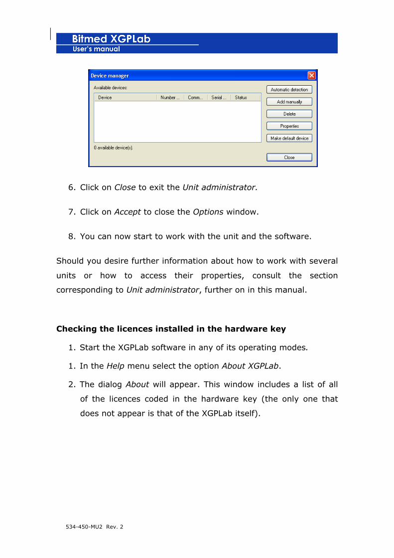
5. The Unit administrator window will open up. Initially, the list of
units registered will be empty. Click on Automatic detection.
The program will detect the unit that is connected and will add
it to the list.
534-450-MU2 Rev. 2
6. Click on Close to exit the Unit administrator.
7. Click on Accept to close the Options window.
8. You can now start to work with the unit and the software.
Should you desire further information about how to work with several
units or how to access their properties, consult the section
corresponding to Unit administrator, further on in this manual.
Checking the licences installed in the hardware key
1. Start the XGPLab software in any of its operating modes.
1. In the Help menu select the option About XGPLab.
2. The dialog About will appear. This window includes a list of all
of the licences coded in the hardware key (the only one that
does not appear is that of the XGPLab itself).

534-450-MU2 Rev. 2
2. Access code
1. Go to the menu Tools > Settings.
2. Select the Device tab and click on the Device manager button.
! Follow these instructions in order to register your Bitmed device within the XGPLab software just in case you have been supplied with an alphanumeric code and not with a HASP hardware key to unlock the software.

534-450-MU2 Rev. 2
3. Make sure that your Bitmed system is connected to the PC and turned on. Click on the Automatic detection button.
4. The software detects your device and shows a new window where you must enter the code supplied with your XGPLab copy.
5. Enter the code and click on Ok. The Bitmed system is now ready for use.
Checking installed licenses with the access code
From Equipment Manager and click the Properties button

534-450-MU2 Rev. 2
A screen with a list of all installed licenses.
Quick start-up
In this section you will find basic information to start to use XGPLab
quickly. Nevertheless, it is necessary to read the complete procedures
for use specified below.
Preparation
1. Install XGPLab.
2. Connect the Bitmed eXim or eXea to the PC and install its
driver.
3. Start XGPLab software.

534-450-MU2 Rev. 2
4. If the program has been started in EEG mode, calibrate the
screen.
5. Record the unit with the program.
Making a new recording in real time
1. With the unit turned on and connected to the PC, click on
Direct communication on the side tool bar or go to the
Communication > Direct communication menu.
2. If you have recorded more than one unit in the program, you
will be asked which one you wish to use to acquire the new
recording.
3. The Recording options window will open. Initially the tab
Predetermined configurations will be active.
4. Select on the list of predetermined configurations the one that
describes the type of study you wish to perform. A
predetermined configuration configures the recording with
certain sensors/electrodes, viewing options, etc., …
5. With the desired predetermined configuration already selected,
click on Read configuration. The recording will be configured
with the established options in the predetermined configuration.
The configuration of the recording can be subsequently
modified in its entirety.
534-450-MU2 Rev. 2
6. If you wish to specify the data of the patient, go to the tab
Recording and click on Recording data. Enter the data of the
patient in the window that opens. When it has finished, click on
Accept.
7. Click on Accept to close the Recording options.
8. The program will ask you for the name and location where you
wish to save the recording. Once this has been selected, the
unit will begin to send data in real time and the monitored
signals will be displayed on the screen.
Finishing the recording in real time
1. When you desire to finish a recording which is being acquired in
real time, click on Stop communication on the side tool bar or
go to the Communication > Stop communication menu.
2. The program will inform you that the recording has finished and
the recording will stop.
Downloading a recording done in residential mode
1. With the unit turned on and connected to the PC, click on
Read unit memory on the side tool bar or go to the
Communication > Read unit memory menu.
2. If you have recorded more than one unit in the program, it will
ask you from which one you wish to download the memory.
534-450-MU2 Rev. 2
3. The Recording options window will open. Initially the tab
Predetermined configurations will be active.
4. Select on the list of predetermined configurations the one that
describes the type of study that was performed in residential
mode. A predetermined configuration configures the recording
with certain sensors/electrodes, viewing options, …
5. With the desired predetermined configuration already selected,
click on Read configuration. The recording will be configured
with the options established in the predetermined configuration.
The configuration of the recording can be subsequently
modified in its entirety.
6. If you wish to specify the data of the patient, go to the tab
Recording and click on Recording data. Insert the data of the
patient in the window that opens. When you have finished, click
on Accept.
7. Click on Accept to close the Recording options.
8. The program will ask you for the name and location where you
wish to save the recording. Once this has been selected, the
data will start to download from the internal memory of the
unit.
9. If more than one recording exists in the memory of the unit,
the program will ask you if you wish to keep each recording in a
different file, or save them together in a single file.

534-450-MU2 Rev. 2
534-450-MU2 Rev. 2
4. THE WORK AREA OF XGPLAB
When XGPLab starts, the work space appears empty, waiting for the
recording of a new test to start or for an existing recording to open.
The following is a description of the elements which make up the
work area once there is a recording open in the program. The
interface of the application changes slightly depending on whether it
has started in the sleep or EEG work mode.
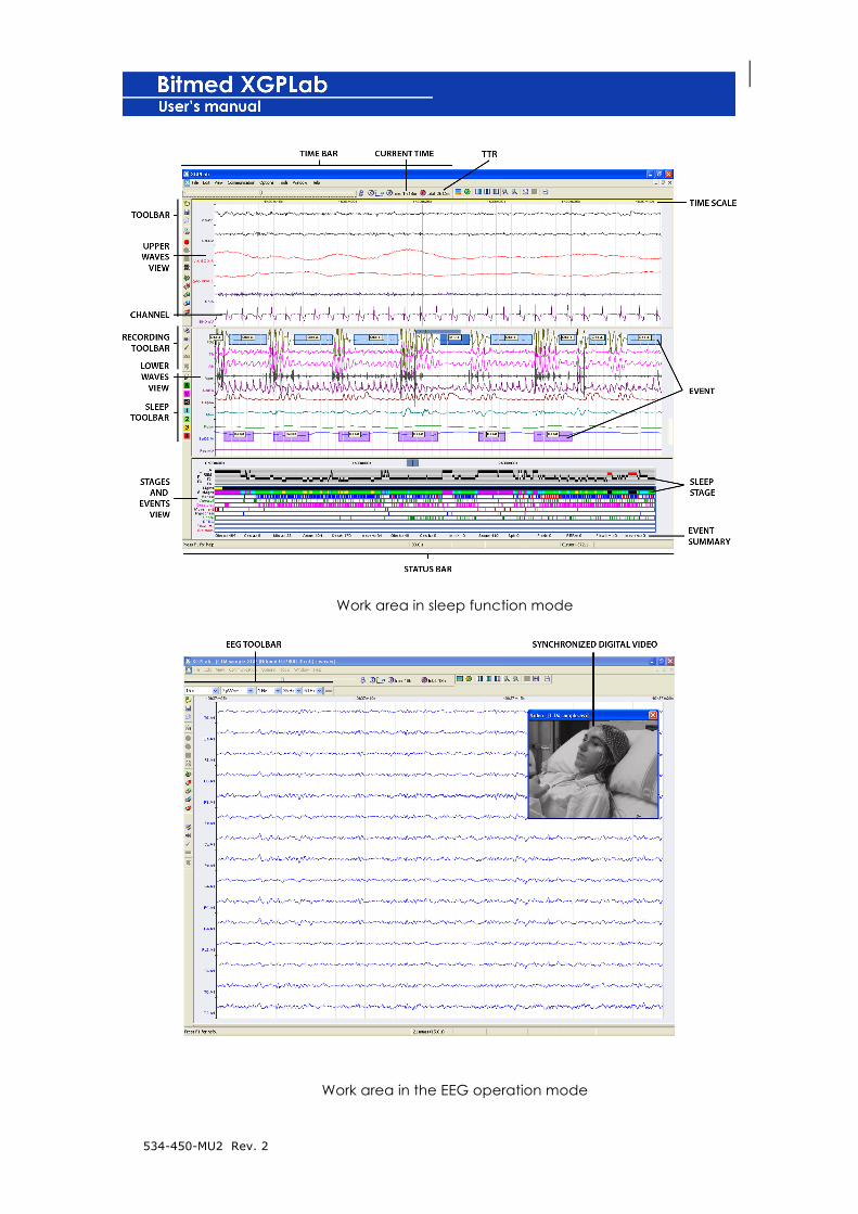
Initially the screen is divided into two different panels: the display of
waves, in which the signals acquired are viewed; and the display of
stages and events, in which a summary of the events, sleep stages
and state of the lights throughout the recording is shown.
Time bar
On the time bar (which appears initially under the menus) is the
scroll bar, which enables the user to move through the recording. To
its right is shown the instant in time (with respect to the start,
displayed as 0h 0 min) on the extreme left of the screen along with
the total recording time.
This bar is only active when a recording is open on screen.

534-450-MU2 Rev. 2
Tool bar
The main tool bar enables the basic operations of the recordings to be
performed, such as opening a recording, saving it, printing it, starting
a new recording in real time or downloading it from the unit memory.
General tool bar
This is only active when a recording is open.
It enables basic operations to be performed, such as accessing the
properties of the recording, or scrolling to a specific point, inserting a
note, or revising the events marked in the recording.
Sleep tool bar
The sleep tool bar is used for the work mode for sleep studies and
only appears when there is a recording open.
It enables the sleep stages to be staged in the polysomnographic
recordings, and also the state of the room lighting to be modified by
hand.
534-450-MU2 Rev. 2
EEG tool bar
The EEG tool bar only appears when a recording is open and the
application has been started in EEG work mode.
It is composed of various lists in which it is possible to choose the
duration of the periods (in seconds or in millimetres per second), the
sensitivity and the filters for the channels. These controls are called
master controls, as by default they are applied to all channels.
Nevertheless, the user has the possibility of individually modifying the
properties of each channel through the Recording options.
The EEG tool bar also includes the button that activates or de-
activates the EEG ruler.
Montage Bar
The Montage bar lists several available montages for the device used.
Select the desired montage, on the list.
Status bar
The status bar is found in the lower zone of the XGPLab work area.
Shown in this bar is information of help concerning the menus and
buttons on which the cursor lights. Information is also included about
the duration of the period of the upper wave display, the time range
setting when there is an active selection, the constant predetermined

534-450-MU2 Rev. 2
active configuration or information used in the manual marking of
apneas and hypopneas.
Wave display
In the wave display the channels are displayed (whether acquired
physically in the unit or generated artificially from operations between
physical channels). The view of the channels is completely
personalizable on the part of the user.
Like the stages and events display, the visible time range in the wave
display is personalizable, although the range of the wave display can
never exceed that of the stages and events display. On the time scale
of the stages and events display the time range that is being viewed
in the wave display is marked in violet.
The waves display can be divided into two parts, although not while a
real-time recording is being carried out. The two wave displays can
be configured with different temporary scales. Each channel can
show or hide itself in any of the two wave displays, so that, for
example, in a sleep study the upper display can be configured to
visualize the fast channels and the lower one to show the slow
channels, each with a different time range. When the lower wave
display is visible, the time range of the upper wave display cannot
exceed that of stages and events. On the time scale of the lower
display the time range being viewed in the upper display is marked in
violet. In the stages and events display, both the upper and the lower
time range being viewed on the wave display are marked in two
different colours
534-450-MU2 Rev. 2
Stages and events display
The stages and events display is divided into several horizontal bars,
the visibility of which is completely configurable. Represented upon
these bars is the following information: state of room light (light
turned on/off), sleep stages and events, both those defined by the
program as well as the user. The sleep events are represented as
vertical lines upon the bars of each type of event, in different colours
to make it easier to read.
On the lower part of the stages and events display is shown the total
number of occurrences of each type of event.
It is also possible to show the hypnogram corresponding to sleep
studies.
Synchronized digital video window
In those recordings in which synchronized digital video has been
captured with the optional XGPVision licence there is a window in
which a video is shown corresponding to the instant in real time.
You will find more information about synchronized digital video later
in this manual.
534-450-MU2 Rev. 2
Work area in sleep function mode
Work area in the EEG operation mode
534-450-MU2 Rev. 2
5. MANAGEMENT OF RECORDINGS
Database
XGPlab provides an optional database module to manage the
recordings (patients and tests).
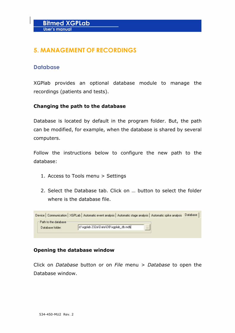
Changing the path to the database
Database is located by default in the program folder. But, the path
can be modified, for example, when the database is shared by several
computers.
Follow the instructions below to configure the new path to the
database:
1. Access to Tools menu > Settings
2. Select the Database tab. Click on … button to select the folder
where is the database file.
Opening the database window
Click on Database button or on File menu > Database to open the
Database window.

534-450-MU2 Rev. 2
Adding a new patient
1. From Database window click on New patient button.
2. Then, fill in the patient data and click on Accept to finish.

534-450-MU2 Rev. 2
Editing a patient data
1. Open the Database window, select the patient to edit from the
list and click on Edit patient button.
2. Edit patient data and press Accept.
Deleting a patient
1. Open the Database window, select the patient to delete and
click on Delete patient button.
2. Confirm.

534-450-MU2 Rev. 2
Linking documents and files to a patient
1. Open the Database window, select the patient to which the files
have to be linked and press the Linked documents button.
2. The Linked documents window is opened. Press the Link
document button.
3. In the Link document window, push the Explore button and
select the file you want to link to the patient

534-450-MU2 Rev. 2
4. The file gets linked to the patient. You can open the linked file
by selecting it in the data base window and pushing the Open
file button.
Starting up a real time test
1. Open the Database window and select the desired patient to
start up a real time test.
2. Click on Real Time Test button and follow the instructions
indicated on the Recording in real time section of the 6.
MAKING A RECORDING chapter.
Downloading the device memory
1. Open the Database window and select a patient from the list.
2. Click on Dowload memory button and follow the instructions
indicated on the Recording in residential mode section of the 6.
MAKING A RECORDING chapter.
Reviewing a patient test
1. Select the patient on the data base window.
2. Select the desired test and press the Review test button.
534-450-MU2 Rev. 2
Viewing the report of a recording
1. Select the patient on the data base window.
2. Select the desired recording and press the View Report button.
3. If the report already exists, it will be displayed. Otherwise, a
new report will be generated for this recording.
Deleting a test
1. Open the Database window and select a patient from the list.
2. Select the test and click on Delete Test button. l
3. Confirm.
Importing a test from the Database
This option allows to add existing tests to the database:
1. Select the desired patient from the list, on the data base
window.
2. Press Import test buttonand select the test file to import to the
database.
Exporting a test
This option allows to export a test to a new file.
1. Open the Database window and select a patient from the list.
2. Select the test file to export and click on Export test button.
3. Choose the name and the location for the new file.
534-450-MU2 Rev. 2
Default filenames
This program offers the possibility of using default names for new
recordings performed, in real time or downloaded from device
memory.
Configuring the default name follow the instructions described below:
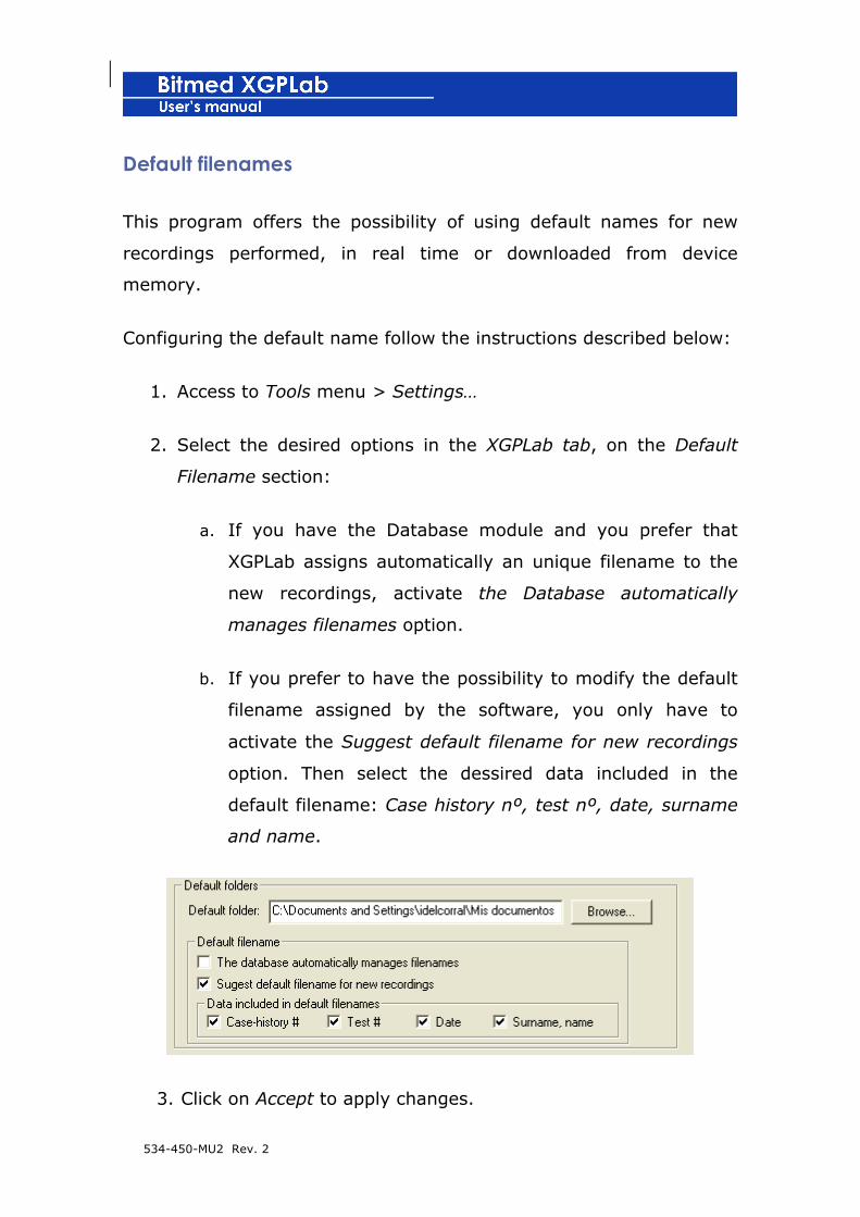
1. Access to Tools menu > Settings…
2. Select the desired options in the XGPLab tab, on the Default
Filename section:
a. If you have the Database module and you prefer that
XGPLab assigns automatically an unique filename to the
new recordings, activate the Database automatically
manages filenames option.
b. If you prefer to have the possibility to modify the default
filename assigned by the software, you only have to
activate the Suggest default filename for new recordings
option. Then select the dessired data included in the
default filename: Case history nº, test nº, date, surname
and name.
3. Click on Accept to apply changes.

534-450-MU2 Rev. 2
Opening a recording
1. Click on Open on the Tool bar or go to the File > Open menu.
2. A window will open enabling you to select the file you wish to
open. On the list Type files you may select whether you wish to
open a recording with the extension xgp, egp, ngp or ng1
(depending on the unit used).
! From XGPLab 2.22 on, all of the recordings are stored
with the extension xgp, regardless of the module used in
the recording. Nevertheless, it is possible to open egp,
ngp or ng1 recordings made with previous versions of
XGPLab.
Saving a recording
1. Click on Save to save the active document or go to the File >
Save menu. If you use the option Save, you can specify a
different name for the file or save it in a folder other than the
one it is in at the moment.
2. The complete recording or the report will be saved, depending
on which document is active at that time.
Sending a recording or a report by e-mail
1. Click on Send or go to the File > Send menu.
534-450-MU2 Rev. 2
2. A new e-mail message will be created which will include as an
attached file the document that is active in XGPLab, whether in
recording or report format.
Exporting the recording
As well as saving the data recordings of XGPLab with their own
format and extension (.xgp), it is possible to export the data of the
recording to other formats, so that you can work with them from
other applications, such as a signal displaying program or a statistics
processing tool.
Currently XGPLab allows you to export the following data formats:
• ASCII: saving in a text file the data corresponding to all or
several recording channels.
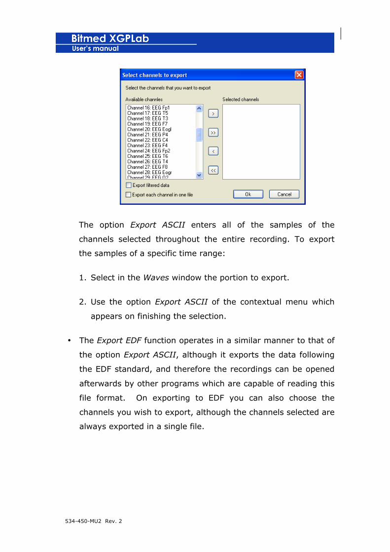
1. Go to the File > Export ASCII menu.
2. A window will appear in which you can choose the channels
you wish to export. If the option Export each channel in a
different file is activated, the data of each channel will be
exported to a different file, with the same name but with the
channel number added. By default, all of the channels
selected are exported to the same file. Within the file is
included information of the channel number and its sampling
frequency. The channel samples are shown below.
534-450-MU2 Rev. 2
The option Export ASCII enters all of the samples of the
channels selected throughout the entire recording. To export
the samples of a specific time range:
1. Select in the Waves window the portion to export.
2. Use the option Export ASCII of the contextual menu which
appears on finishing the selection.
• The Export EDF function operates in a similar manner to that of
the option Export ASCII, although it exports the data following
the EDF standard, and therefore the recordings can be opened
afterwards by other programs which are capable of reading this
file format. On exporting to EDF you can also choose the
channels you wish to export, although the channels selected are
always exported in a single file.

534-450-MU2 Rev. 2
Printing the recording
With XGPLab you can either print out the period that is being viewed
on the screen or the complete recording.
1. With the recording active in the period you wish to print, click
on Print on the tool bar or go to the menu File > Print.
2. Select in the dialog the elements you wish to be included in the
printout. For example, you can add a heading with the user’s
data and/or his logo. These options are saved each time
printing is done.
You can also choose in this window if you wish to print the
complete recording or only the period being displayed on the
screen.
3. The recording range will be printed with the same configuration
that is visible on screen. .

534-450-MU2 Rev. 2
Preview of the printout of a recording period
1. Go to the menu File > Preliminary presentation.
2. Select in the dialog the elements you wish to be included in the
preview. You can also choose in this window whether you wish
to print the complete recording or only the period that is being
viewed on the screen.
3. If you wish, you can print what you see on the screen from the
preliminary presentation.

534-450-MU2 Rev. 2
6. MAKING A RECORDING
This section will provide new users of XGPLab software and the
Bitmed eXim and Bitmed eXea systems with some basic instructions
to perform a sleep study.
Types of studies
As described in the manual of your Bitmed eXim or eXea system,
there are basically two ways of working with the units: in real time or
in residential time. Thus, two different procedures are given for each
of these situations.
Recording in real time
A recording in real time is one in which the unit is connected to the
computer during the recording, so that the signals it is acquiring are
displayed in real time on the computer screen.
The recording is stored on the hard disk of the computer, in a file
with the extension xgp. However, the recording is also stored in the
internal memory of the unit, provided there is enough space for it, for
security purposes.
It is also possible to capture synchronized video with
neurophysiological/polygraphic signals, for enhanced monitoring of
the patient. In this case, it is generated in the same folder in which
the xgp file keeps a new file with the .avi extension.

534-450-MU2 Rev. 2
! The capture of the digital video implies the need for a
large amount of free space on your hard disk, which is
determined by the resolution and number of photograms
with which the capture is made.
We recommend having at least 20 Gb free if carrying out
a sleep or EEG test of long duration.
For short EEG video tests the requisites are lower.
! The acquisition of digital video is not available in
recordings made in residential mode.
Preparing the recording
Make sure that the connection cable is connected to the USB port of
your PC, and to the corresponding connector of your Bitmed eXim or
eXea. To obtain more information, consult the unit manual.
Connect the power source of the unit and turn it on.
The unit must be recorded in the program as described previously.
Deletion of memory
Before starting the recording it is advisable to delete the contents of
the unit memory. In this way we will ensure that the recording is also
stored correctly in the internal memory of the unit. If a problem
occurs later (such as, for example, the collapse of the power

534-450-MU2 Rev. 2
network) the unit will continue storing the recording in residential
mode and can be recovered later.
! Before deleting the memory contents of the unit, make
sure that any previous recording you wish to keep has
been downloaded.
1. Start the XGPLab software in its usual work mode.
2. click on on the tool bar or go to the Communication >
delete memory from the unit menu.
3. If you have more than one unit recorded in XGPLab you will be
asked to indicate which unit you wish to delete the memory
from.
4. A message will appear asking you for confirmation that you
effectively wish to continue. Click on Accept.
5. Then a bar will appear indicating the progress of the deletion.
The duration of the operation depends on the type of unit and
the memory installed.
6. Turn off the unit and turn it on again.
Placement of electrodes and sensors
In the unit manual you will find a complete description of how to
place the electrodes and other sensors, depending on the type of test
you wish to carry out.
534-450-MU2 Rev. 2
Starting to make the recording
Once the electrodes and sensors have been placed on the patient, the
recording can be started using the software. In this step the data of
the patient will be entered in the test and the impedance of the
electrodes will be checked.
1. Make sure that no recording is open in XGPLab. It is not
possible to carry out a new recording in real time if one is
already open.
2. Click on or go to the menu Communication > Direct
communication.
3. If you have more than one piece of equipment, you will be
asked to indicate which one you are going to use to make the
recording.
4. The dialog box Record options appears in which the options for
configuration of the recording are entered, such as the sensors
that are to be used, the screen viewing order, filters, duration
of periods, etc.
Although you can personalize this data each time you start a
new recording, it is more convenient to save all of the
parameters under a predetermined configuration, which can
then either be loaded directly or set up as the default mode for
all of the new recordings made.
You will find more information about the management of
predetermined configurations later in this manual.
534-450-MU2 Rev. 2
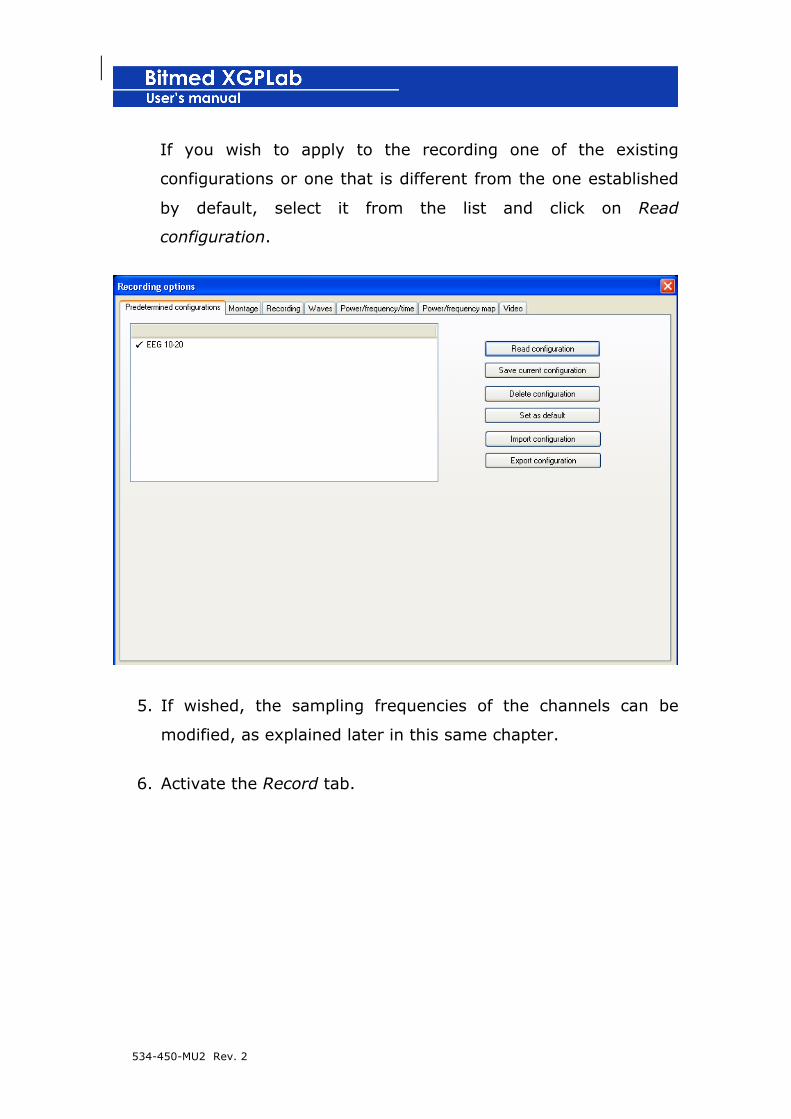
If you wish to apply to the recording one of the existing
configurations or one that is different from the one established
by default, select it from the list and click on Read
configuration.
5. If wished, the sampling frequencies of the channels can be
modified, as explained later in this same chapter.
6. Activate the Record tab.

534-450-MU2 Rev. 2
Click on Record data. A dialog will open so that the user can
enter data identifying the patient and the recording. This data
appears both in the report generated by the program and in the
printout of periods of the recording. Such data are: name,
surname(s), address, town, province, telephone number, age,
height, weight, body mass index (calculated by clicking on
Calculate), sex, name under which the file of the recording has
been saved, date the recording was made, time of starting the
recording and the name of the person in charge of making such
recording and of the doctor who requested the test. The field
Observations and Diagnosis also appears.
When you have finished, click on Accept. You can return at any
time to edit the data contained in this window, by accessing the
Recording options and then going to the Record tab.

534-450-MU2 Rev. 2
7. If you wish to check the impedances of the electrodes activate
the box Carry out measurement of impedances before
beginning a new recording in the Record tab. You can also
activate the option Measure impedances before continuing to
make a recording if you wish to check the impedances each
time the recording pauses and resumes.
8. If you have the licence for the module of XGPVision optional
software and you wish to capture digital video, activate the
Video tab. This tab is not visible if you do not have the
XGPVision module.

534-450-MU2 Rev. 2
Configure the options of video and audio acquisition according
to your preferences. You will find more information on the
acquisition of video and audio later in this manual.
9. Click on Accept to close the Recording options.
10. XGPLab will ask you to select the name with which the
recording will be saved. Select the folder and the name with which
you wish to save the new recording and click on Save.
11. The unit will start the acquisition of the
neurophysiological/polygraphic signals and these will be viewed on
the screen in real time. Furthermore, the data will also be stored
in the internal memory of the unit.

534-450-MU2 Rev. 2
Pause and resumption of a recording
It is possible to pause the recording momentarily at any time and
resume it later on.
1. Click on or go to the Communication > Pause/continue
direct communication menu.
2. The acquisition of the recording will stop.
If a recording is paused which included capture of video, the
video window will also be paused; thus, if one moves through
the recording, the video does not synchronize with the instant
in time in which it is being displayed. To access this feature,
you must stop the communication by clicking on Stop direction
communication. However, take into account that once the
communication of a recording with video has stopped, it cannot
be continued.
3. To continue with the recording from the point at which it was
paused, click again on the same button or on the same menu
option.
Finishing the recording
1. Click on or go to the Communication > Stop direct
communication menu.
2. After a few seconds the recording will stop and the equipment
will stop recording data in its internal memory.
If a recording which includes video capture is stopped, the
recording cannot continue afterwards. Once the communication

534-450-MU2 Rev. 2
has stopped you may review the recording, so that the video
synchronizes totally with the instant in time that you are viewing.
Impedance measurement during the recording
During the recording, it is possible to check the impedance of the
electrodes at any time.
For this, click the button of Impedance Measurement of the toolbar.
In the record will be inserted an annotation indicating the moment in
which was carried out the measurement of impedances.
Preview of the signals from the amplifier before starting a
recording
Before saving in the hard drive of the computer signals from the
amplifier; it is normal to display them on the screen to check that
sensors and/or electrodes are properly placed.
When the program is in a preview mode, the data are not saved in
the recording. To indicate that the application is in this special way
the background color changes and appears a label on the screen.
534-450-MU2 Rev. 2
Starting all the records in preview mode
Follow these steps to start all new records in preview mode:
1. Go to the Tools menu > Settings….
2. Select the XGPLab tab and activate the start all real time
recordings in preview mode option. In this way, you do not need
to start manually preview mode on the beginning of each new
registration.
3. Click OK to implement the changes.
Starting the preview mode
You can start the preview mode at any time during the acquisition of
a real time record by clicking the button preview mode of the toolbar.
Salir del modo de previsualización
Cuando desea pasar del modo previsualización al modo de adquisición
normal y que las señales queden registradas en su ordenador haga
clic en el botón Modo previsualización de la barra de herramientas.
Finishing the preview mode
If you want to change from the preview mode to normal acquisition
mode, click the button preview mode of the toolbar. Then, the signals
will be recorded on your computer.

534-450-MU2 Rev. 2
Recording with photic stimulator (manual control)
If your photic stimulator is manually controlled from the device follow
the steps outlined in this section.
Configuring the photic stimulator
The photic stimulator is connected to a serial port of the computer,
and therefore it is necessary to indicate to the software, the port to
which it has been connected.
1. In the XGPLab software go to the Tools menu > Settings....
2. Activate the tab Communication.
3. Indicate the serial port to which the photic stimulator has been
connected in the text box

534-450-MU2 Rev. 2
4. Click on Accept to close the Settings... menu.
Recording with photic stimulation
1. Start the recording in the usual way for real time, until you
reach the point in which the Recording Options appear.
2. Activate the Waves tab.
3. Uncheck the box Ignore events coming from the external
triggers generator.

534-450-MU2 Rev. 2
4. Continue configuring the recording in the same way as for any
other recording in real time.
5. Once the acquisition of the recording has started, each time the
photic stimulator emits a flash, the program will automatically
insert a mark for the Flash event, with the mark being shown
both on the bar of the event and on the EEG signal if it has
been thus configured.
Recording with photic stimulator (software control)
If the photic stimulator is to be controlled from the XGPLab software
(no manual controls) follow the steps outlined in this section.
Recording with photic stimulation
1. Start a new recording as any other real time recording.
2. In the Master control bar click the photic stimulation button.
3. Next click on the Settings icon.
534-450-MU2 Rev. 2
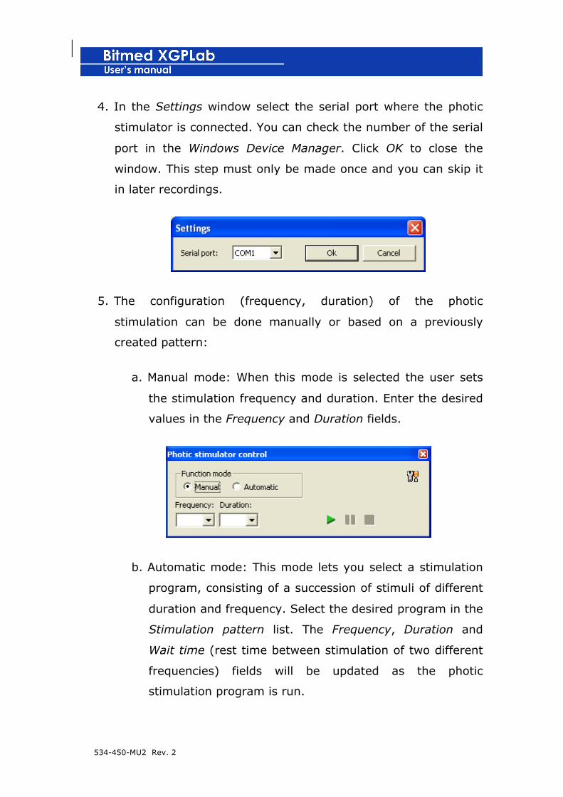
4. In the Settings window select the serial port where the photic
stimulator is connected. You can check the number of the serial
port in the Windows Device Manager. Click OK to close the
window. This step must only be made once and you can skip it
in later recordings.
5. The configuration (frequency, duration) of the photic
stimulation can be done manually or based on a previously
created pattern:
a. Manual mode: When this mode is selected the user sets
the stimulation frequency and duration. Enter the desired
values in the Frequency and Duration fields.
b. Automatic mode: This mode lets you select a stimulation
program, consisting of a succession of stimuli of different
duration and frequency. Select the desired program in the
Stimulation pattern list. The Frequency, Duration and
Wait time (rest time between stimulation of two different
frequencies) fields will be updated as the photic
stimulation program is run.

534-450-MU2 Rev. 2
The Photic stimulation patterns folder is to be found under
the XGPLab software installation folder (similar to
C:/Program Files/Bitmed/XGPLabx.xx). All the automatic
stimulation programs are stored in this folder, one program
in each file with the ps extension. You can create new ps
files or modify any of the existing ones. Each file has the
following structure:
Pattern name
frequency duration wait time
frequency duration wait time
…
frequency duration wait time
The pattern name is the one listed in the Stimulation pattern list, under the Photic stimulation control window.
You can add as many frequency duration wait time lines as desired. The program will execute one after another.
6. Click the Start stimulation icon to start emitting light stimuli.
A mark is inserted in the recording in order to indicate the start
of the stimulation, as well as its frequency.

534-450-MU2 Rev. 2
Press the Pause icon to pause the stimulation or Stop to
end it completely.
Both situations are reflected in the registry with their respective
marks.
Recording in residential mode
Recording in residential mode (also called holter mode) is that in
which the unit is not connected to the computer during the recording.
The data are stored in the internal memory of the unit and once the
recording is finished they are transferred to the computer for review.
! The acquisition of digital video is not available in
recordings made in residential mode.
Preparing the recording
Connect the power source to the unit. If you do not wish to use the
power source, make sure that the internal battery has a sufficient
534-450-MU2 Rev. 2
charge to carry out the test you wish to make. To know more about
the battery charge status light, consult the unit manual.
Deleting the memory
Before starting the recording it is advisable to delete the contents of
the unit memory. In this way we can make sure that there is
sufficient space in the internal memory of the unit for the new
recording. If you wish to make more than one recording in residential
mode you can do so. Later, when downloading the data to the PC,
you can separate the data in several different recordings, just as they
were made.
! Before deleting the unit memory contents, make sure
that any previous recording you wish to keep has been
downloaded.
1. Start the XGPLab software in its normal work mode.
2. Click on on the tool bar or go to the menu Communication
> delete the memory of the unit.
3. If you have more than one unit registered with XGPLab, you
will be asked to indicate which unit you wish to delete the
memory from.
4. A message will appear asking you for confirmation that you
want to continue. Click on Accept.
534-450-MU2 Rev. 2
5. A bar will then appear indicating the progress of the deletion.
The duration of the operation will depend on the type of unit
and the memory installed.
Configuring the unit to work in residential mode
Before starting a recording in residential mode, it is necessary to
prepare the unit. Basically this means establishing the sampling
frequencies of the channels. If we always carry out the same type of
test, it will be sufficient to configure the unit once only.
By default, all of the channels are recorded with a sampling frequency
of 100 Hz, but it is possible for this to vary depending on the sensors
connected to each channel. For example, you can make a residential
study of EEG with frequencies of 250 or 500 Hz or configure the
acquisition of a polygraphic signal to 50 Hz.
1. Connect the unit to the USB port of your PC.
2. Start the XGPLab software in your normal work mode.
3. Turn on the Bitmed eXim or eXea.
4. In XGPLab, click on or go to the Communication >
Configure unit menu.
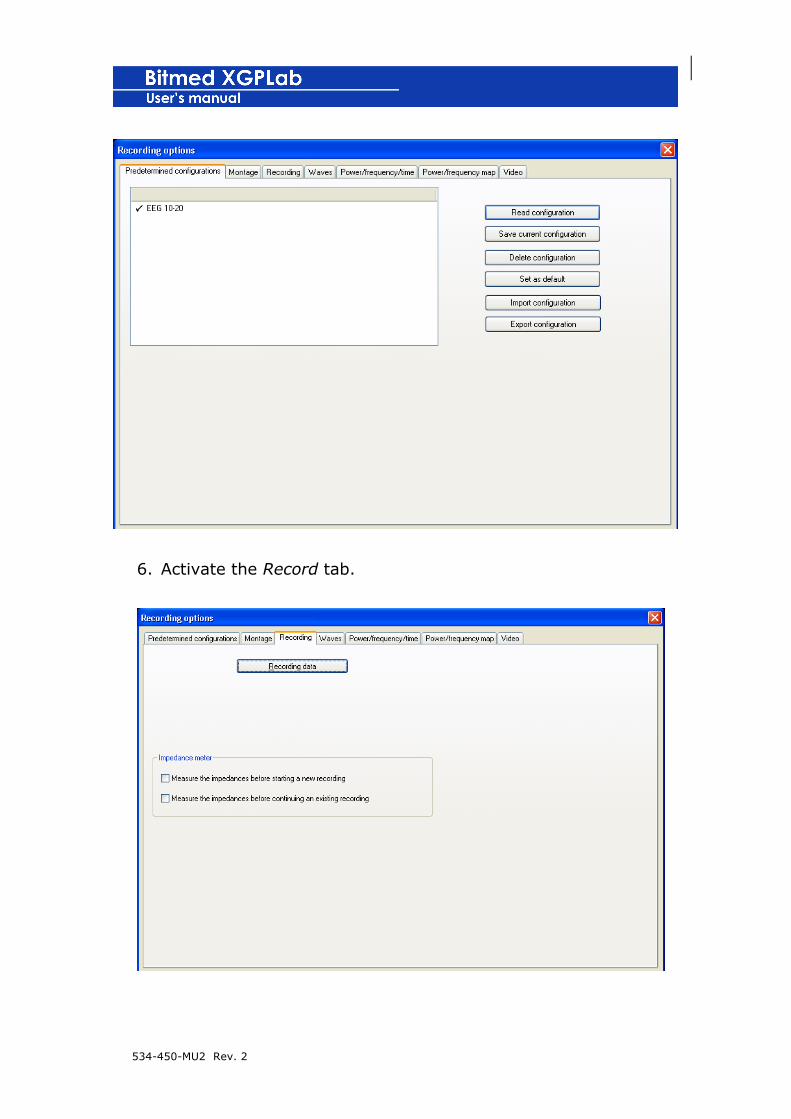
5. The Recording options will appear, as if it were going to make a
real-time recording or to dump the memory of the unit.
6. If you have a configuration created with the channels that you
wish to acquire and their sampling frequencies, read it. If not,
modify the sampling frequencies, as specified later.

534-450-MU2 Rev. 2
7. When you have finished, click on Accept. The software will
configure the unit and it will be ready to record in residential
mode.
Placement of electrodes and sensors
In the unit manual you will find a complete description of the
placement of the electrodes and other sensors, depending on the
type of test you wish to carry out.
Starting the recording
To start the recording in the internal memory, you only have to turn
on the unit. After 15 seconds, the unit will start to record the data in
its memory.
Finishing the recording
To finish the recording, simply turn off the unit.
Transferring the data from the unit memory to the computer
Once the recording has been made in residential mode, it is
necessary to download the data from the unit to the computer for
revision and analysis.
1. Connect the unit to the USB port of your PC.
2. Start the XGPLab software in its usual work mode.
3. Turn on the Bitmed eXim or eXea.
4. In the XGPLab, click on or go to the menu Communication
> Read unit memory.

534-450-MU2 Rev. 2
! If the download takes more than 15 seconds to start from
the moment the unit is turned on, the unit will begin to
record data in the internal memory (unless it has no
more memory available), Thus, a new section of invalid
data, which the user can separate and discard later, will
be added to the recording for those seconds.
5. The dialog box Recording Options appears where the recording
configuration options are entered, such as the sensors used in
the recording, screen viewing order, filters, duration of periods.
Although you can personalize this data each time you make a
new recording in residential mode, it is easier to save all of the
parameters under a predetermined configuration, which can
later be loaded directly or set up as a default mode for all of the
new recordings made. You will find more information on the
management of predetermined configurations later in this
manual.
If you wish to apply to the one of the existing configurations
recording, or one that is different from the one established by
default, select it on the list and click on Read configuration.
534-450-MU2 Rev. 2
6. Activate the Record tab.
534-450-MU2 Rev. 2
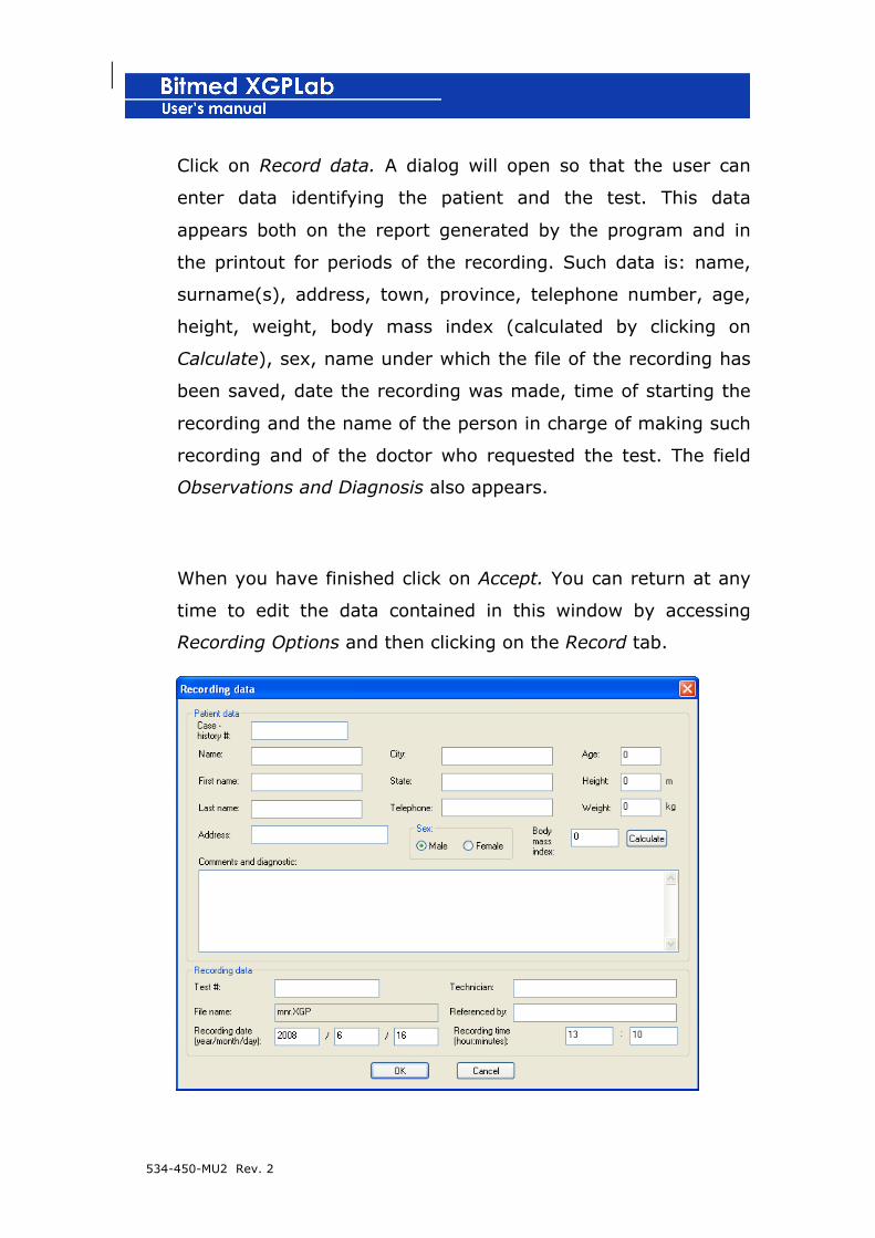
Click on Record data. A dialog will open so that the user can
enter data identifying the patient and the test. This data
appears both on the report generated by the program and in
the printout for periods of the recording. Such data is: name,
surname(s), address, town, province, telephone number, age,
height, weight, body mass index (calculated by clicking on
Calculate), sex, name under which the file of the recording has
been saved, date the recording was made, time of starting the
recording and the name of the person in charge of making such
recording and of the doctor who requested the test. The field
Observations and Diagnosis also appears.
When you have finished click on Accept. You can return at any
time to edit the data contained in this window by accessing
Recording Options and then clicking on the Record tab.

534-450-MU2 Rev. 2
7. Click on Accept to close the Recording Options.
8. XGPLab will ask you to select the name under which the
recording will be saved. Select the folder and the name with
which you wish to save the new recording and click on Save.
9. Data transference will begin from the memory of the unit to the
computer. The progress bar which appears on the screen will
indicate the percentage of the operation that is complete, as it
is being completed.
10. When the download has finished, the program will inform
you that the operation has finished.
11. If there is only one recording in the memory, it is simply
shown in a new document. If there is more than one recording,
the program will show a window with a list of the existing
recordings and their duration, and ask the user whether they
wish to separate the recordings into different documents, or
keep them as a single one, with one recording following on
immediately after the other.

534-450-MU2 Rev. 2
Modifying the sampling frequency of the channels
By default, all of the channels are recorded with a sampling frequency
of 100 Hz. However, it is possible to vary this depending on the
sensors connected to each channel. For example, you can make a
residential study of EEG with frequencies of 250 or 500 Hz or
configure the acquisition of a polygraphic signal at 50 Hz.
The sampling frequency of the channels can only be modified before
starting the acquisition of a new recording, either when you make a
real-time recording or when you configure the unit to record in
residential mode.

534-450-MU2 Rev. 2
! Sampling frequencies other than those established by
default should only be configured by personnel that is
adequately trained
1. When you start the recording in real time or are going to
configure the unit to work in residential mode, the Recording
Options will appear.
2. Activate the Assembly tab.
3. On the list of visible channels you must select the channel to
which you wish to change the sampling frequency and click
on Properties.
4. The Channel properties window will open. On the list
Acquisition frequency select the sampling frequency that the
channel is going to use.

534-450-MU2 Rev. 2
5. Click on Close to exit Channel properties.
6. Repeat points 3 to 5 with all those channels in which you
wish to change the sampling frequency.
7. In the Recording options click on Accept to continue with the
recording in real time or with the configuration of the unit.
Changing the real-time representation mode
XGPLab allows two modes of representation of signals in real time.
When the continuous representation mode is selected, the signals are
represented from left to right on the screen. On reaching the right

534-450-MU2 Rev. 2
end, the signals move to the left and the representation continues on
the right.
However, in the EEG representation mode when the right end of the
screen is reached, it returns again to the left and continues there, so
that the new data overwrite the old data. A vertical red line indicates
the position in which it is being represented.
To change the mode of representation:
1. Open the Recording options from the Options > Recording
options menu.
2. Activate the Waves tab.
3. From the Representation mode menu select the desired
mode of representation.
4. Click on Accept to apply the changes.
Using the chronometer in real-time recordings
XGPLab has a chronometer that can be used to time different events
or parts of a test. This feature is especially useful for EEG recordings.
For example, the time that the patient must hyperventilate can be
easily controlled according to the protocol used.
When starting the chronometer a note is inserted automatically into
the recording with the text CR START. Likewise, on stopping the
chronometer, the chronometer inserts a note with the text CR FIN.

534-450-MU2 Rev. 2
The chronometer appears on the right of the status bar and can only
be used while a recording is being acquired in real time.
Starting/stopping the chronometer
With the recording in real time in progress, press the SPACE key to
start the counting of the chronometer. When you wish to stop it, you
only have to press the SPACE key. You can start and stop the
chronometer as many times as you wish throughout the recording.
534-450-MU2 Rev. 2
7 REVISING A RECORDING
This section describes how to revise a recording, scale axes,
(amplitudes, temporary scale), carry out an automatic analysis and
mark events. The revision can be used either as a substitute for
automatic analysis or as a complement to it.
Adjust the screen time
The temporary scale of the upper part of the recording screen shows
the recording time and the size of the period on a recording screen.
The size of the period also appears on the status bar.
Adjust the screen time with the keys + and - and icons
Use the keys + and – to duplicate or divide by two the visible time on
screen. The icons on the time bar can also be used. and .
Specify the number of seconds of each period
1. Open the Recording options from the menu Options >
Recording options.
2. Activate the Waves tab.
3. In this submenu there are three text boxes which specify the
range of time visible in each display: one for the upper
waves display, another for the lower one and another for the
one for stages and events, each with its own associated
button See complete recording on a screen to compress all
of the recording into a single screen. With this option, the

534-450-MU2 Rev. 2
signals are not appreciated most of the channels, but an
overall global impression is given of the variation of
amplitude of the signals throughout the recording (this may
be particularly useful for the channels of pulse and oxygen
saturation and to quickly see whether a sensor has come
loose at some time during the night).
These adjustments can be applied to either the upper
display, the lower display, or the events-stages display,
although the time range of the upper wave display cannot
exceed that of the lower one, neither can that of the lower
one exceed that of the display of stages and events.
Using the EEG tool bar
Specify the duration of the periods in seconds or in mm/s from the
first list on the left on the EEG tool bar. The values listed appear in
seconds or in mm/s, depending on how the software has been
configured. You must have previously calibrated the screen so that
the scale in mm/s fits reality. Consult section 3, First steps with
XGPLab to obtain more information about how to calibrate the screen.

534-450-MU2 Rev. 2
If you wish to alternate between seconds and mm/s:
1. Go to Tools menu > Settings...
2. Activate the XGPLab tab.
3. Select See periods on the list in the option desired: seconds
or mm/s.
4.
Zoom on a recording range
1. Click on the left button of the mouse, on any of the channels, at
the point where you wish to establish the start of the range to
be amplified.
2. Without releasing the left button, drag the mouse to the point
where you wish to finish the range to be amplified and release
the button.
534-450-MU2 Rev. 2
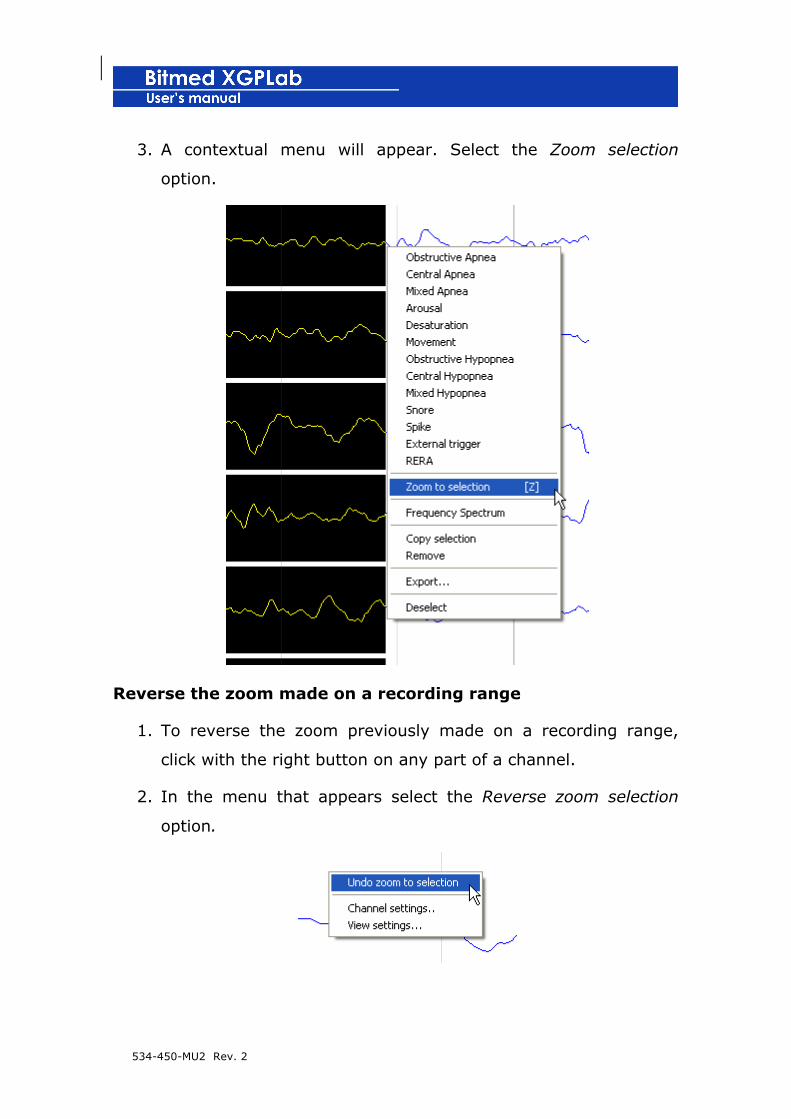
3. A contextual menu will appear. Select the Zoom selection
option.
Reverse the zoom made on a recording range
1. To reverse the zoom previously made on a recording range,
click with the right button on any part of a channel.
2. In the menu that appears select the Reverse zoom selection
option.
534-450-MU2 Rev. 2
Modifying the time reference
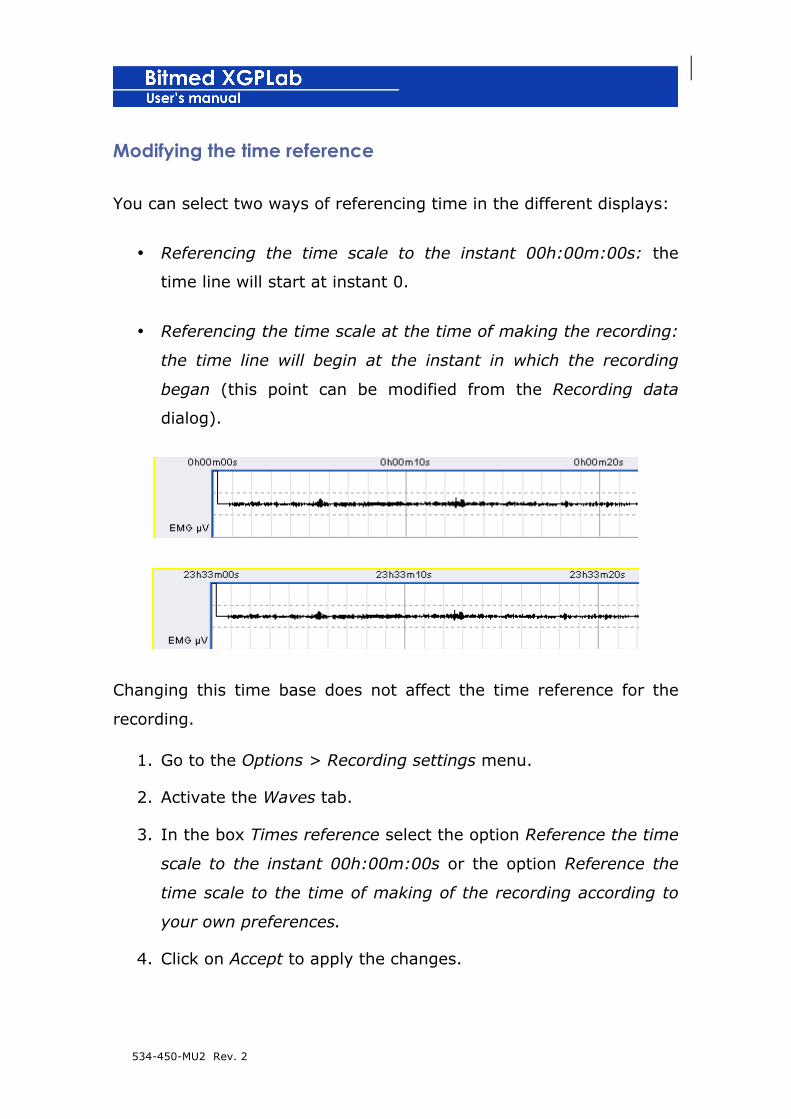
You can select two ways of referencing time in the different displays:
• Referencing the time scale to the instant 00h:00m:00s: the
time line will start at instant 0.
• Referencing the time scale at the time of making the recording:
the time line will begin at the instant in which the recording
began (this point can be modified from the Recording data
dialog).
Changing this time base does not affect the time reference for the
recording.
1. Go to the Options > Recording settings menu.
2. Activate the Waves tab.
3. In the box Times reference select the option Reference the time
scale to the instant 00h:00m:00s or the option Reference the
time scale to the time of making of the recording according to
your own preferences.
4. Click on Accept to apply the changes.

534-450-MU2 Rev. 2
Moving through the recording
Using the time bar
The time bar allows you to move through the recording quickly.
Simply drag the mark in the scroll bar to move to another instant in
the recording. The movement will take place in the visit that is active
at that moment (the one framed in yellow).
If the option Adjust navigation of the recording to complete periods in
the window Recording options > Program is active, the movement will
be made in units of time equal to the duration of the periods. That is
to say, if it takes a period of 30 seconds to move with the time bar,
the start of a period on screen will coincide with the start of a minute
or with the 30th second of a minute.
Using the keyboard
The following keys will allow you to move through the recording:
• Home: this takes you to the start of the recording
• End: this takes you to the end of the recording
• Page down: this advances to the next period
• Page up: this takes you to the previous period
• ← (only valid when the option Adjust navigation of the
recording to complete periods is not active): limited return,
depending on the duration of the periods configured, but always
less than that of a complete period.
• → (only valid when the option Adjust navigation of the
recording to complete periods is not active): limited advance,
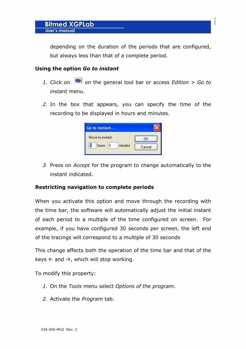
534-450-MU2 Rev. 2
depending on the duration of the periods that are configured,
but always less than that of a complete period.
Using the option Go to instant
1. Click on on the general tool bar or access Edition > Go to
instant menu.
2. In the box that appears, you can specify the time of the
recording to be displayed in hours and minutes.
3. Press on Accept for the program to change automatically to the
instant indicated.
Restricting navigation to complete periods
When you activate this option and move through the recording with
the time bar, the software will automatically adjust the initial instant
of each period to a multiple of the time configured on screen. For
example, if you have configured 30 seconds per screen, the left end
of the tracings will correspond to a multiple of 30 seconds
This change affects both the operation of the time bar and that of the
keys Ñ and Ò, which will stop working.
To modify this property:
1. On the Tools menu select Options of the program.
2. Activate the Program tab.

534-450-MU2 Rev. 2
3. Activate or de-activate the option Adjust navigation of the
recording to complete periods during review.
4. Click on Accept to close the window and apply the changes.
Notes in the recording
The user can enter notes throughout the recording with important
comments. During direct communication, this option can be very
useful for the user to make a note of his visual observations of the
patient (if he/she is anxious, moves, has woken up…) or to note
changes in the application of the CPAP, supply of medication, etc. All
of the notes are listed in the report of the recording, together with
the instant of time in which they were entered.
The program enters a note automatically each time a recording is
made in real time or in residential mode.
A note is also inserted each time the user events marker is pressed.
The notes are shown on the time scale of the waves display.
Inserting a note
2. In the Edition menu select Insert note
3. A box will appear in which the user must enter the text he/she
wishes to insert as a note. If the recording is in direct
communication, the note will appear superimposed in the same
instant as the recording that is being acquired, whereas if a
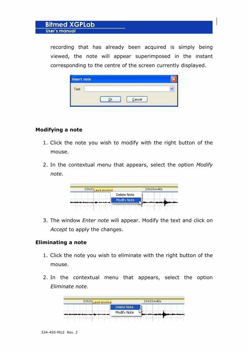
534-450-MU2 Rev. 2
recording that has already been acquired is simply being
viewed, the note will appear superimposed in the instant
corresponding to the centre of the screen currently displayed.
Modifying a note
1. Click the note you wish to modify with the right button of the
mouse.
2. In the contextual menu that appears, select the option Modify
note.
3. The window Enter note will appear. Modify the text and click on
Accept to apply the changes.
Eliminating a note
1. Click the note you wish to eliminate with the right button of the
mouse.
2. In the contextual menu that appears, select the option
Eliminate note.

534-450-MU2 Rev. 2
Showing/hiding the notes
1. Open the Recording options from Options > Recording options
or using the corresponding tab on the side tool bar.
2. Activate the Waves tab.
3. Activate the option See notes if you wish to display the notes on
screen or de-activate it if you wish to hide them.
4. Click on Accept to apply the changes.
Adjusting the amplitudes of the channels
Adjust the amplitudes with the keys ↑ and ↓
1. Using the left button of the mouse, double-click on those
channels in which you wish to modify the amplitude. The
bottom of the channel will turn from white to orange.
2. Use the keys ↑ and ↓ to increase or decrease the amplitude of
the channels selected.
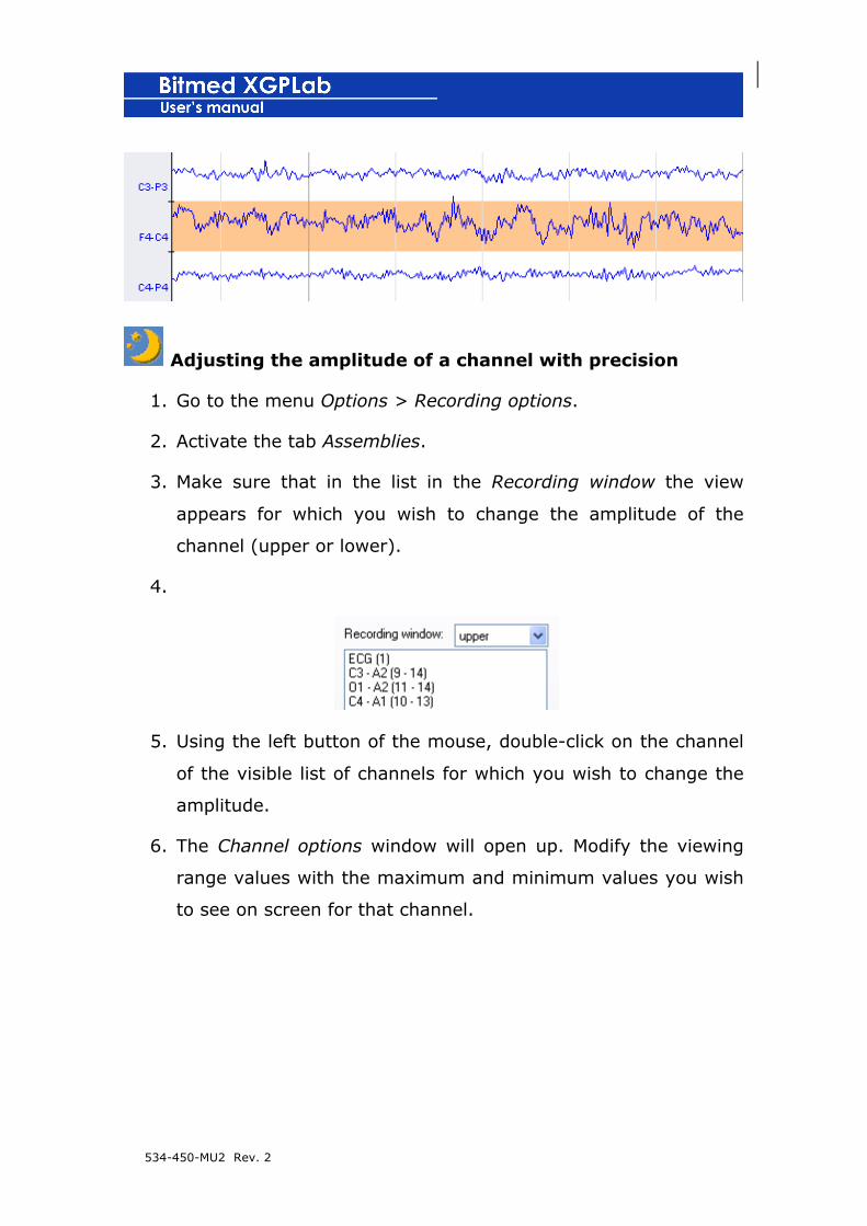
534-450-MU2 Rev. 2
Adjusting the amplitude of a channel with precision
1. Go to the menu Options > Recording options.
2. Activate the tab Assemblies.
3. Make sure that in the list in the Recording window the view
appears for which you wish to change the amplitude of the
channel (upper or lower).
4.
5. Using the left button of the mouse, double-click on the channel
of the visible list of channels for which you wish to change the
amplitude.
6. The Channel options window will open up. Modify the viewing
range values with the maximum and minimum values you wish
to see on screen for that channel.

534-450-MU2 Rev. 2
7. When you have finished click on Close.
8. In the Recording options window click on Accept to apply the
changes.
Using the EEG tool bar
The second list on the left allows the sensitivity or amplitude to be
modified for all the channels to which the master control is applied
(applied to all by default). The screen must have been previously
calibrated so that the sensitivity coincides with reality. Consult
section 3, First steps with XGPLab to obtain more information about
how to calibrate the screen.
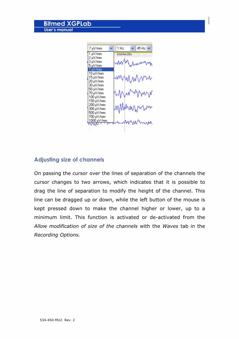
534-450-MU2 Rev. 2
Adjusting size of channels
On passing the cursor over the lines of separation of the channels the
cursor changes to two arrows, which indicates that it is possible to
drag the line of separation to modify the height of the channel. This
line can be dragged up or down, while the left button of the mouse is
kept pressed down to make the channel higher or lower, up to a
minimum limit. This function is activated or de-activated from the
Allow modification of size of the channels with the Waves tab in the
Recording Options.
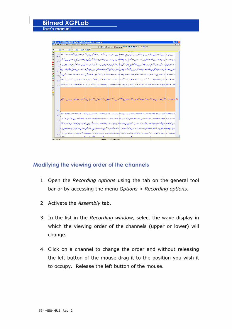
534-450-MU2 Rev. 2
Modifying the viewing order of the channels
1. Open the Recording options using the tab on the general tool
bar or by accessing the menu Options > Recording options.
2. Activate the Assembly tab.
3. In the list in the Recording window, select the wave display in
which the viewing order of the channels (upper or lower) will
change.
4. Click on a channel to change the order and without releasing
the left button of the mouse drag it to the position you wish it
to occupy. Release the left button of the mouse.

534-450-MU2 Rev. 2
5. When you have finished adjusting the order of the channels
click on Accept to apply the changes to the recording.
Modifying the name of the channels in the tracing
Using the Recording options
1. Open the Recording options from the tab on the general tool
bar or from the Options > Recording options menu.
2. Activate the Waves tab.
3. From the Description of the channels list you can select four
modes for displaying the name of the channels:
• Detailed: this includes the name of the channel, the long
name of the sensor associated to it and its description.
• Short: this only shows the abbreviated name of the
channel, or the name of the electrode if it has been
defined.
• Outside the channel: this is similar to the preceding
mode, but shows the title to the left of the channel and
hides the scale.

534-450-MU2 Rev. 2
• No description: this hides any type of text about the
channels.
4. When you have finished, click on Accept to apply the changes
to the recording.
Using the keyboard
You can also modify the mode in which the channel names are
displayed from the keyboard. Use the “C” key to alternate between
the four possible representation options.
Hiding or showing separation between channels
1. Open the Recording options using the general tool bar or by
accessing the Options > Recording options menu.
2. Activate the Waves tab.
3. Activate or de-activate the option See separator bars between
channels.
4. Click on Accept to apply the changes and close the Recording
options.

534-450-MU2 Rev. 2
Adding and removing channels to wave displays
Adding channels
1. Go to the Options > Recording options menu.
2. Activate the Assembly tab.
3. In the list in the Recording window select the upper or lower
wave display you wish to configure.
4. On the right part of the window will appear all of the input
channels for your unit. Click on one of them to add it to the list
of visible channels.

534-450-MU2 Rev. 2
5. When you have added all of the channels required, click on
Accept to close the window and apply the changes.

534-450-MU2 Rev. 2
Eliminating a channel
1. Go to the menu Options > Recording options.
2. Activate the tab Assembly.
3. In the list in the Recording window select the upper or lower
wave display you wish to configure.
4. In the list of visible channels select the one you wish to
eliminate.
5. Click on Eliminate and the channel will disappear from the list of
visible channels.
6. Click on to close the window and apply the changes.
Eliminating all of the channels
1. Go to the Options > Recording options menu.
2. Activate the tab Assembly.
3. In the list in the Recording window select the upper or lower
wave display you wish to configure.
4. Click on Eliminate all to eliminate all channels at once.
5. Click on Accept to close the window and apply the changes.

534-450-MU2 Rev. 2
Configuring the signal to each input channel
Before acquiring a new recording or checking an existing one, it is
necessary to indicate to the software which sensors/signals were
connected to each of the input channels of your Bitmed recording
unit. When you have configured them all, you may save the changes
as a predetermined configuration that can subsequently be used
again.
1. Go to the menu Options > Recording options.
2. Activate the tab Assembly.
3. Supposing that the channel is already on the list of visible
channels, double-click it or select it and click on Properties.
4. The window of the Channel properties will open. In the list
Signal type select the sensor that has been connected to the
corresponding channel of the unit.
! If the sensor you wish to connect to your unit does not
correspond to any of those that appear on the list of
signal types, contact Sibel S.A. to receive instructions as
to how to use it.

534-450-MU2 Rev. 2
5. Click on Close to close the window.
6. In the window of the Recording options click on Accept to apply
the changes.
Cambiar los filtros software
Using the cannel settings
The low and high pass filters can be changed in both EEG and Sleep
working modes from the Channel settings window, as seen before.
If master control is activated for the cannel you want to modify then
you must uncheck the Use master control option. Otherwise, if you

534-450-MU2 Rev. 2
want to use the filters currently selected in the master control bar
then check that option.
Using the master control bar
The EEG working mode allows you to change the filters from the
master control bar for all channels with the master control activated.
If any of the channels on screen is selected (any cannel with an
orange background) the changes made to the filters will be applied
only to those channels.
The filter icon enables or disables all the filters with a single click.
Creating derivations of EEG/EOG
To create a derivation of EEG or EOG you will need two reference
channels (single-pole). Some units, such as the Bitmed EGP800 with
35 channels, the Bitmed eXea PSG series 4 and 5, or the Bitmed eXea
EEG and Ultra, have hardware reference channels. In other cases you
might wish to convert differential (bipolar) channels into reference
(single-pole) channels thanks to a bridge between channels (you will
find more information about this in the user’s manual for the unit). In
this case it is necessary to tell the software that you have converted
it into a reference channel.
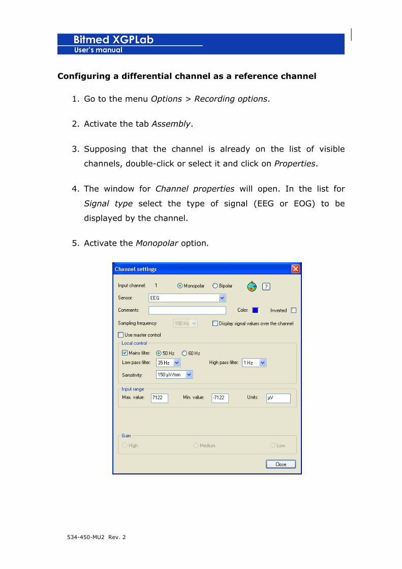
534-450-MU2 Rev. 2
Configuring a differential channel as a reference channel
1. Go to the menu Options > Recording options.
2. Activate the tab Assembly.
3. Supposing that the channel is already on the list of visible
channels, double-click or select it and click on Properties.
4. The window for Channel properties will open. In the list for
Signal type select the type of signal (EEG or EOG) to be
displayed by the channel.
5. Activate the Monopolar option.

534-450-MU2 Rev. 2
6. You can manually add the corresponding text to the position of
the electrode in the text box Additional description or click on
the head icon, which opens the Electrode map.
7. In the Electrode map, click on the electrode that you have
connected to the channel you are configuring and press on
Accept.
8. In the Channel properties the name of the electrode will
automatically be added to the Additional description text box.
9. Click on Close to close the Channel properties.
10. Observe that the name of the channel has been modified in
the list of visible channels of the tab Assembly with the name
of the electrode that has been connected to the channel
appearing in its place.
Creating a branch establishing the reference for a channel
1. Open the Recording options from Options > Options of the
recording.

534-450-MU2 Rev. 2
2. Activate the Assembly tab.
3. Select the wave display for the channel for which you wish to
establish a reference.
4. In the list of visible channels, select the channel for which you
wish to establish the reference. Remember that the channel
selected must be a reference channel.
5. Open up the Reference list and select the reference you wish to
use for the channel. It can be any of the other reference
electrodes or an averaged reference (later, we will describe how
to configure an averaged reference).
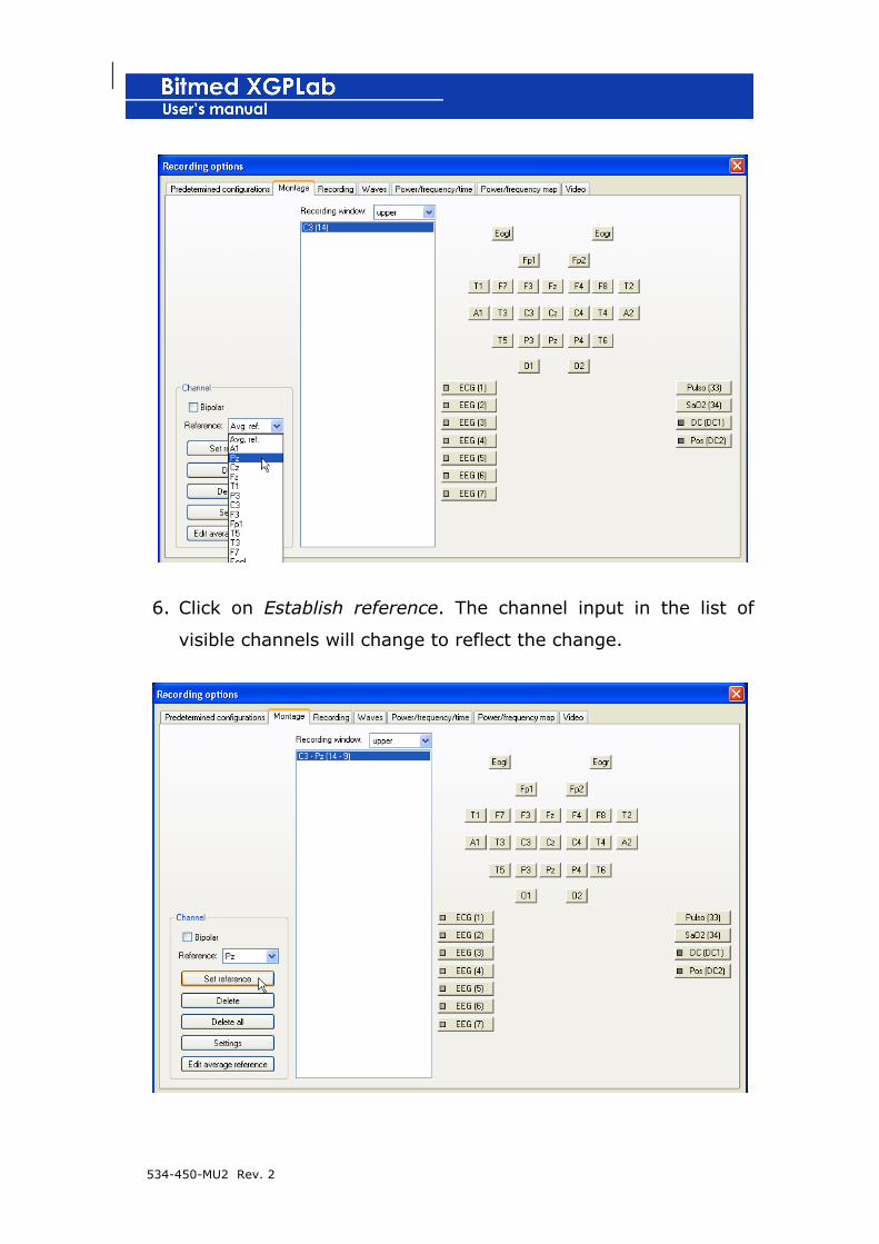
534-450-MU2 Rev. 2
6. Click on Establish reference. The channel input in the list of
visible channels will change to reflect the change.
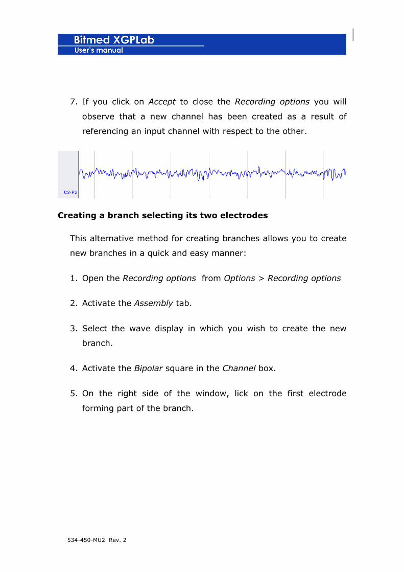
534-450-MU2 Rev. 2
7. If you click on Accept to close the Recording options you will
observe that a new channel has been created as a result of
referencing an input channel with respect to the other.
Creating a branch selecting its two electrodes
This alternative method for creating branches allows you to create
new branches in a quick and easy manner:
1. Open the Recording options from Options > Recording options
2. Activate the Assembly tab.
3. Select the wave display in which you wish to create the new
branch.
4. Activate the Bipolar square in the Channel box.
5. On the right side of the window, lick on the first electrode
forming part of the branch.
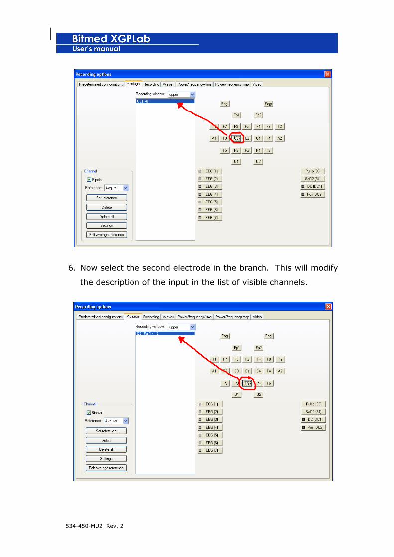
534-450-MU2 Rev. 2
6. Now select the second electrode in the branch. This will modify
the description of the input in the list of visible channels.
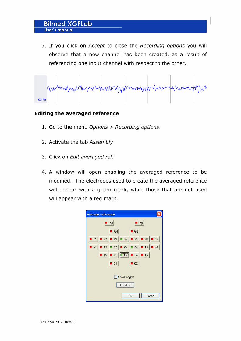
534-450-MU2 Rev. 2
7. If you click on Accept to close the Recording options you will
observe that a new channel has been created, as a result of
referencing one input channel with respect to the other.
Editing the averaged reference
1. Go to the menu Options > Recording options.
2. Activate the tab Assembly
3. Click on Edit averaged ref.
4. A window will open enabling the averaged reference to be
modified. The electrodes used to create the averaged reference
will appear with a green mark, while those that are not used
will appear with a red mark.
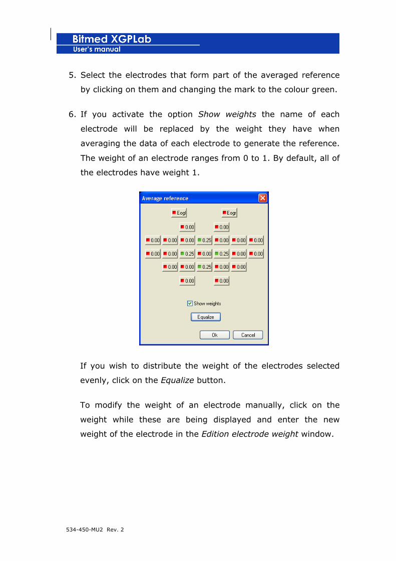
534-450-MU2 Rev. 2
5. Select the electrodes that form part of the averaged reference
by clicking on them and changing the mark to the colour green.
6. If you activate the option Show weights the name of each
electrode will be replaced by the weight they have when
averaging the data of each electrode to generate the reference.
The weight of an electrode ranges from 0 to 1. By default, all of
the electrodes have weight 1.
If you wish to distribute the weight of the electrodes selected
evenly, click on the Equalize button.
To modify the weight of an electrode manually, click on the
weight while these are being displayed and enter the new
weight of the electrode in the Edition electrode weight window.

534-450-MU2 Rev. 2
7. When you have finished editing the averaged reference, click on
the averaged reference; click on Accept to close the window.
Changing colour for tracing of signals
Each type of signal will be configured by default with a different
colour, although each colour can be easily modified.
1. Go to the menu Options > Recording options.
2. Activate the Assembly tab.
3. Supposing that the channel is already in the list of visible
channels, double-click or select it and click on Properties.
4. The window for Channel properties will open and a Colour box
with the colour currently configured for the tracing of the signal
will be displayed.
5. Click on the colour square to open the colour selection dialog
and select the new colour for the tracing of the signal. Click on
Accept when you have finished.

534-450-MU2 Rev. 2
6. Close Channel properties, by clicking on the Close button.
7. Returning to the Recording options click on Accept to apply the
changes.
Showing values for a channel
If you so desire, you can show the real values for the signals on the
tracing itself, at regular intervals.
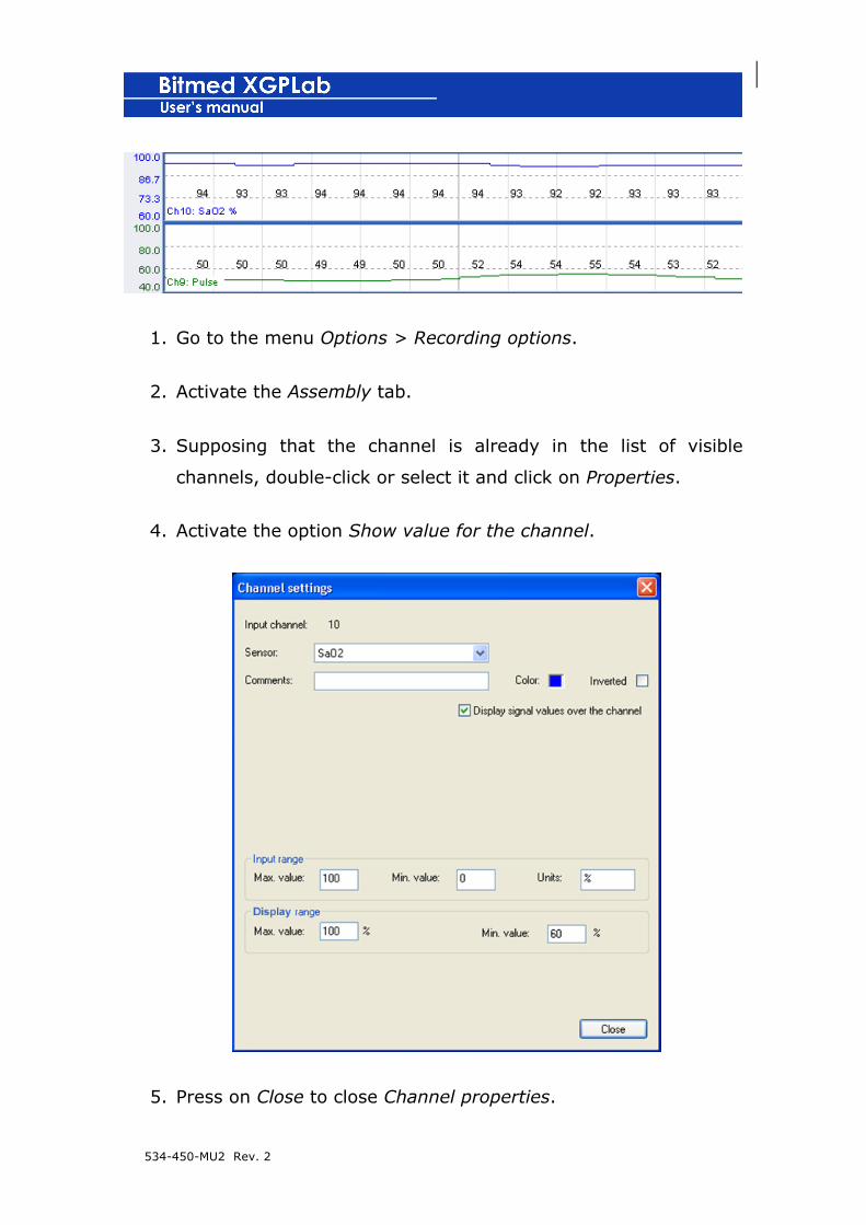
534-450-MU2 Rev. 2
1. Go to the menu Options > Recording options.
2. Activate the Assembly tab.
3. Supposing that the channel is already in the list of visible
channels, double-click or select it and click on Properties.
4. Activate the option Show value for the channel.
5. Press on Close to close Channel properties.

534-450-MU2 Rev. 2
6. Returning to the Recording options, click on Accept to apply the
changes.
Cursor with numerical values
The numerical value cursor is a vertical line which the user can move
freely on the screen. Shown on the status bar is the value of the
signal in the position and channel where the cursor has alighted. To
show this:
1. Go to the menu Options > Recording options.
2. Activate the Waves tab.
3. Mark the square corresponding to the option See cursor with
numerical values.
4. Click on Accept to apply the changes.
When the lower wave display is visible, a cursor is also shown which
is synchronized with that of the upper one, so that it always marks
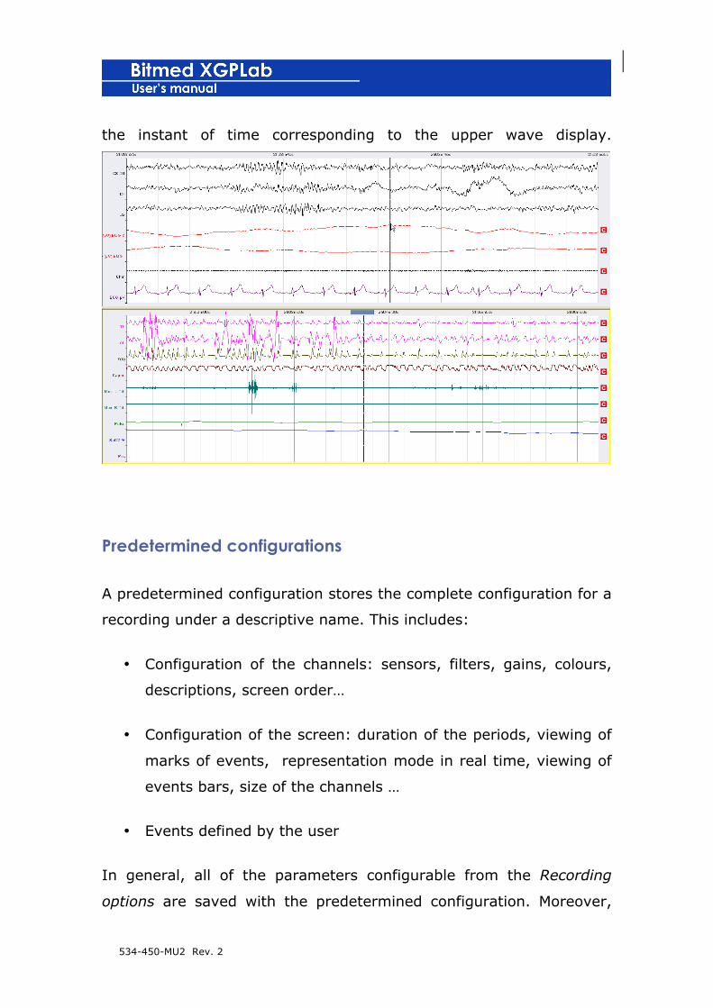
534-450-MU2 Rev. 2
the instant of time corresponding to the upper wave display.
Predetermined configurations
A predetermined configuration stores the complete configuration for a
recording under a descriptive name. This includes:
• Configuration of the channels: sensors, filters, gains, colours,
descriptions, screen order…
• Configuration of the screen: duration of the periods, viewing of
marks of events, representation mode in real time, viewing of
events bars, size of the channels …
• Events defined by the user
In general, all of the parameters configurable from the Recording
options are saved with the predetermined configuration. Moreover,

534-450-MU2 Rev. 2
other data is also saved, as is the case of the types of events defined
by the user.
The predetermined configurations are saved with a name and can
later be loaded and applied to the recording at any time, whether on
starting a real-time recording, configuring a unit for use in residential
mode, downloading a recording from the memory of the unit or
during the review.
Furthermore, if you normally carry out the same type of test you can
establish a default configuration so that the software can apply it
automatically to all new recordings.
The predetermined configurations are managed from the
Predetermined configurations of the Recording options.

534-450-MU2 Rev. 2
Saving a predetermined configuration
8. Once you have configured the recording in accordance with
your own requirements, go to the Recording options.
9. Activate the tab Predetermined configurations.
10. Click on Save current configuration.
11. The program will ask you for the name you are going to
assign to the predetermined configuration. Enter this and click
on Accept. In the event of a configuration already existing with
the same name, the program will ask you for confirmation to
overwrite it.
Loading and applying a predetermined configuration
1. Go to the menu Options > Recording options.
2. Activate the tab Predetermined configurations.
3. From the list of available configurations, select the one you
wish to apply.
4. Click on the button Read configuration.
5. Click on Accept to close the Recording options and apply the
changes.

534-450-MU2 Rev. 2
Load and apply a predetermined configuration from the
montage bar
The predetermined configuration which is selected in any moment can
be changed and applied to the recording by selecting any of the
predetermined configurations listed in the montage bar.
Establishing a predetermined default configuration for new
recordings
1. Go to the menu Options > Recording settings.
2. Activate the tab Predetermined configurations.
3. From the list of available configurations select the one you wish
to establish as default.
4. Click on the button Establish as default.
5. The program will ask you if you wish to apply the configuration
to the active recording.
6. Click on Accept to close the Recording options and apply the
changes.
Exporting a predetermined configuration

534-450-MU2 Rev. 2
XGPLab allows you to export a configuration to a file, so that you can
import it in another computer easily.
1. Go to the menu Options > Recording options.
2. Activate the tab Predetermined configurations.
3. From the list of available configurations select the one you wish
to export.
4. Click on the button Export configuration.
5. A dialog will appear for you to select the name of the file that
will store the predetermined configuration and the folder where
you wish to save it.
6. The configuration will be saved in a file with extension .xcp
Importing a predetermined configuration
1. Go to the menu Options > Recording options.
2. Activate the tab Predetermined configurations.
3. Click on the button Import configuration.
4. A dialog will appear in which you must select the xcp file
corresponding to the predetermined configuration you wish to
import.
5. The predetermined configuration will be added to the list.
Eliminating a predetermined configuration
534-450-MU2 Rev. 2
1. Go to the Options > Recording options menu.
2. Activate the tab Predetermined configurations.
3. From the list of predetermined configurations select the one
you wish to eliminate.
4. Click on Delete configuration.
Event types
An event is an incident in time which is marked on certain channels
and on the event occurrence bar.
By default, in XGPLab several events are defined which the user
cannot eliminate: obstructive apnea, central apnea, mixed apnea,
obstructive hypopnea, central hypopnea, mixed hypopnea, flow
limitation, arousal, arousal caused by movement, RERA, movement,
desaturation, snoring ,flash (corresponding to events coming from a
generator of external triggers, as can be the case with a photic
stimulator) and spike.
Moreover, the user can define a maximum of 10 additional events.
These personalized events are stored in each recording and can be
saved together with a predetermined configuration.
You can check the existing events and their configuration from the
Tools > Event types menu.

534-450-MU2 Rev. 2
Add a new event type
5. Open the Event types window from Tools > Event types.
6. Click on New.
7. For each new type of event it is necessary to define a long
name and a short one. The long name will appear together
with the other types of events on adding a new event to the
recording, on manually revising the events and in the legend in
the lower part of the screen. The short name is used at the
534-450-MU2 Rev. 2
time of showing the number of total events for that particular
type. When you have finished click on Accept.
8. Close the window Event types.
Eliminating a type of event
1. Make sure that you have previously deleted all of the
occurrences of the type of event you wish to eliminate.
2. Open the window Event types from Tools > Event types.
3. Select the event type you wish to eliminate and click on
Eliminate.
4. Close the Event types window.
Modifying the representation of the events
1. Open the Event types window from Tools > Event types.
2. Select the type of event you wish to personalize and click on
Properties.
3. From the list Mark on choose on which channels the event will
be marked:

534-450-MU2 Rev. 2
• Active channel: the events are marked upon the channel
on which you have clicked with the mouse when inserting
the event manually.
• Specific channel: activates the Channel list, in which you
can select a specific type of signal.
• Group of channels: activates the list Group of channels,
where you can choose the name of a group of channels.
Also activates the Edit groups button. This button opens a
new window from which we can easily manage new
groups of channels. It is possible to eliminate any of the
existing groups, as well as create new groups with the
selection of channels chosen by the user.
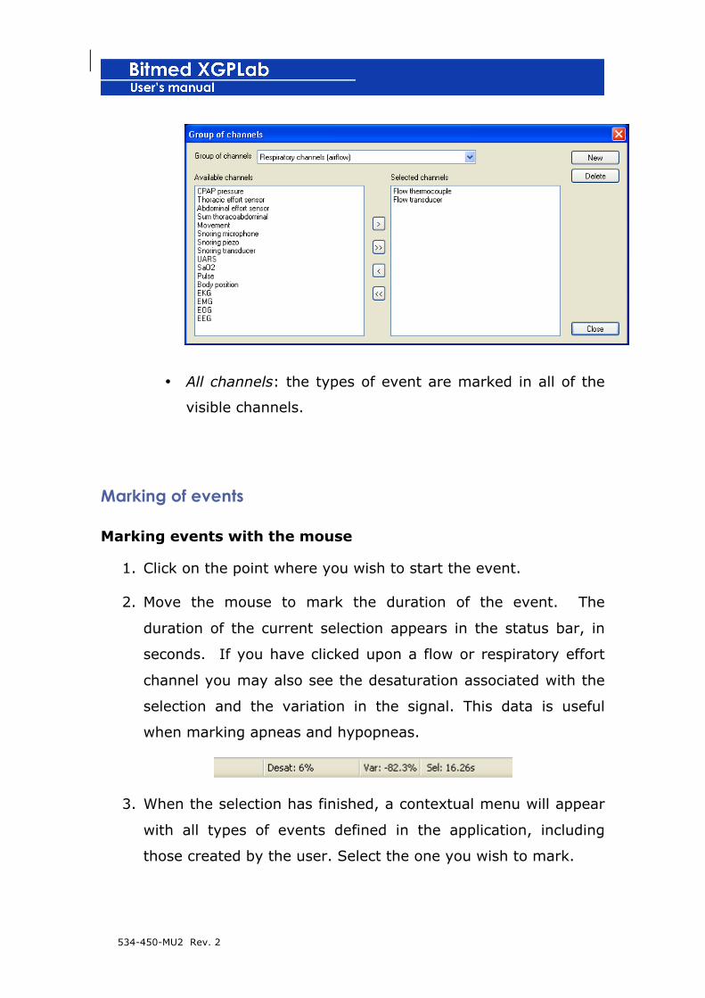
534-450-MU2 Rev. 2
• All channels: the types of event are marked in all of the
visible channels.
Marking of events
Marking events with the mouse
1. Click on the point where you wish to start the event.
2. Move the mouse to mark the duration of the event. The
duration of the current selection appears in the status bar, in
seconds. If you have clicked upon a flow or respiratory effort
channel you may also see the desaturation associated with the
selection and the variation in the signal. This data is useful
when marking apneas and hypopneas.
3. When the selection has finished, a contextual menu will appear
with all types of events defined in the application, including
those created by the user. Select the one you wish to mark.
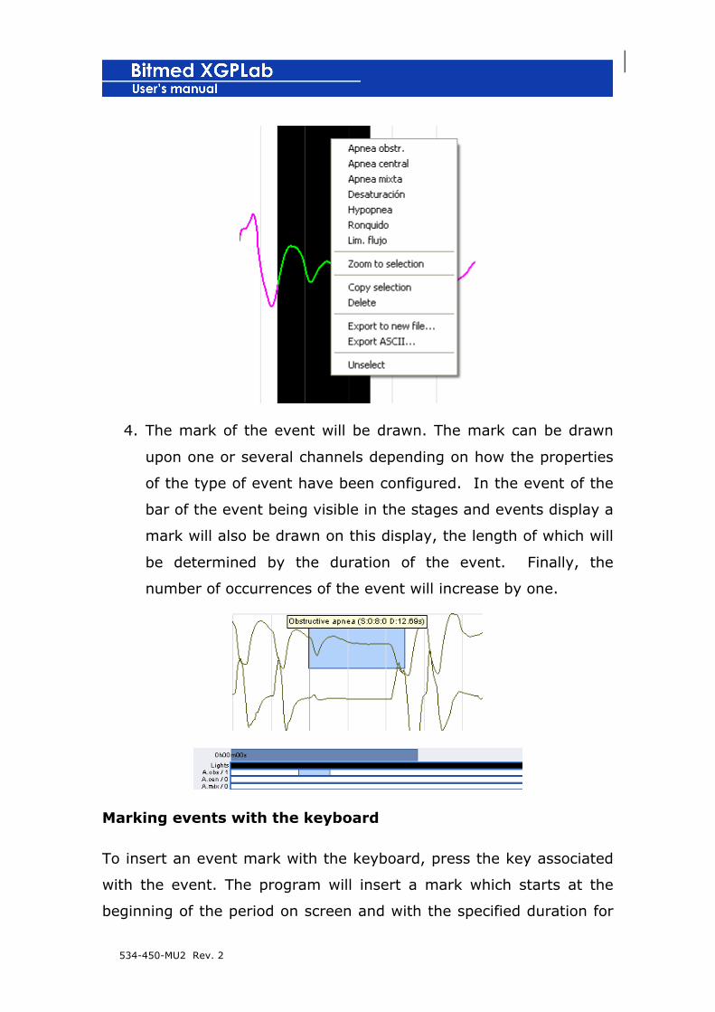
534-450-MU2 Rev. 2
4. The mark of the event will be drawn. The mark can be drawn
upon one or several channels depending on how the properties
of the type of event have been configured. In the event of the
bar of the event being visible in the stages and events display a
mark will also be drawn on this display, the length of which will
be determined by the duration of the event. Finally, the
number of occurrences of the event will increase by one.
Marking events with the keyboard
To insert an event mark with the keyboard, press the key associated
with the event. The program will insert a mark which starts at the
beginning of the period on screen and with the specified duration for
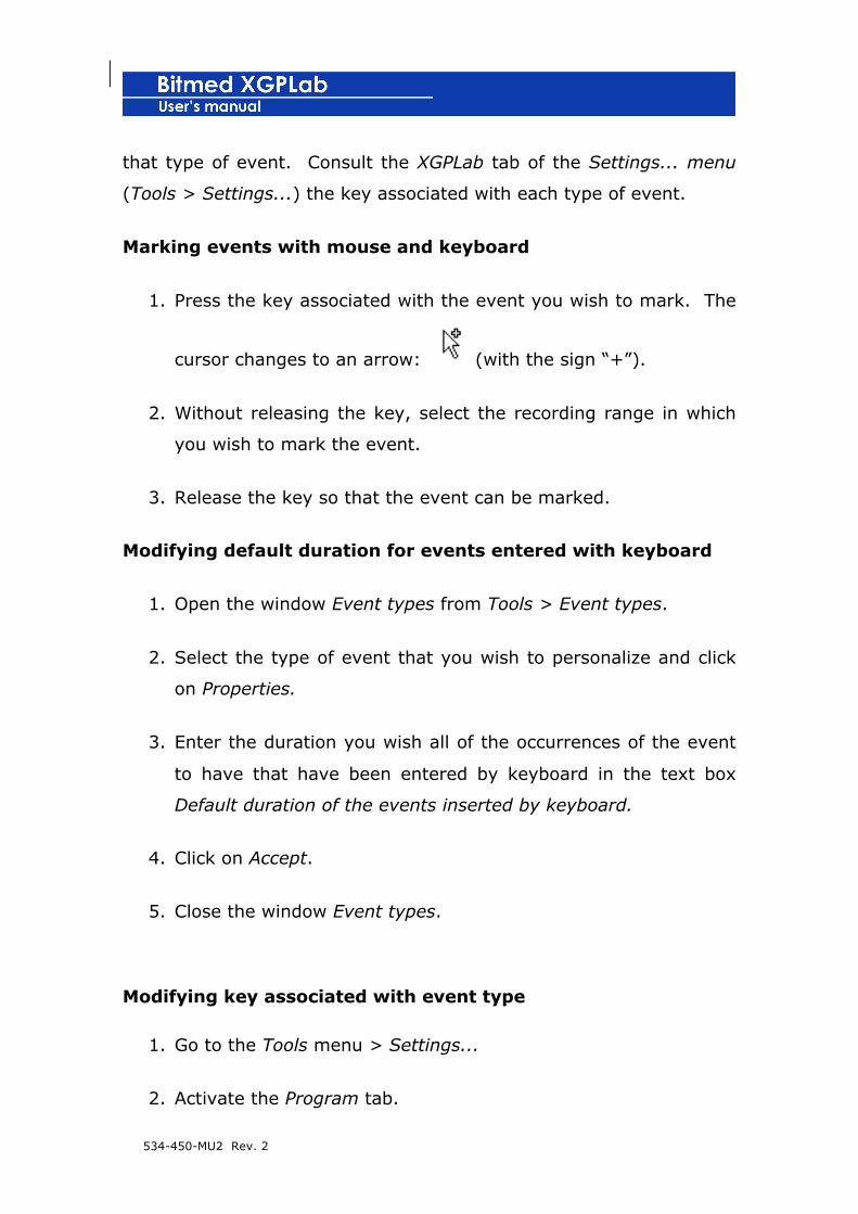
534-450-MU2 Rev. 2
that type of event. Consult the XGPLab tab of the Settings... menu
(Tools > Settings...) the key associated with each type of event.
Marking events with mouse and keyboard
1. Press the key associated with the event you wish to mark. The
cursor changes to an arrow: (with the sign “+”).
2. Without releasing the key, select the recording range in which
you wish to mark the event.
3. Release the key so that the event can be marked.
Modifying default duration for events entered with keyboard
1. Open the window Event types from Tools > Event types.
2. Select the type of event that you wish to personalize and click
on Properties.
3. Enter the duration you wish all of the occurrences of the event
to have that have been entered by keyboard in the text box
Default duration of the events inserted by keyboard.
4. Click on Accept.
5. Close the window Event types.
Modifying key associated with event type
1. Go to the Tools menu > Settings...
2. Activate the Program tab.
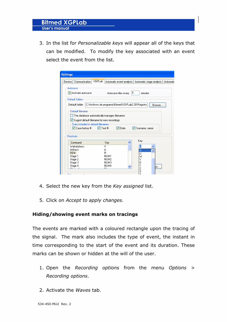
534-450-MU2 Rev. 2
3. In the list for Personalizable keys will appear all of the keys that
can be modified. To modify the key associated with an event
select the event from the list.
4. Select the new key from the Key assigned list.
5. Click on Accept to apply changes.
Hiding/showing event marks on tracings
The events are marked with a coloured rectangle upon the tracing of
the signal. The mark also includes the type of event, the instant in
time corresponding to the start of the event and its duration. These
marks can be shown or hidden at the will of the user.
1. Open the Recording options from the menu Options >
Recording options.
2. Activate the Waves tab.
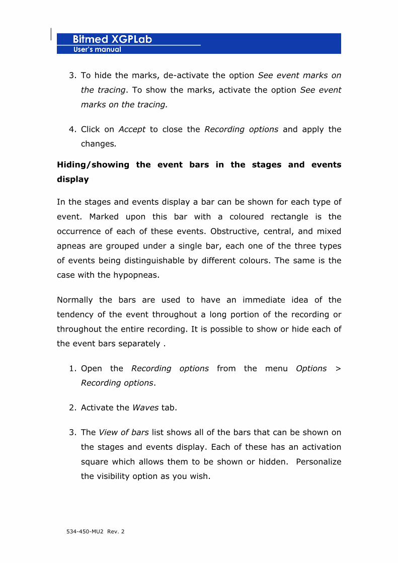
534-450-MU2 Rev. 2
3. To hide the marks, de-activate the option See event marks on
the tracing. To show the marks, activate the option See event
marks on the tracing.
4. Click on Accept to close the Recording options and apply the
changes.
Hiding/showing the event bars in the stages and events
display
In the stages and events display a bar can be shown for each type of
event. Marked upon this bar with a coloured rectangle is the
occurrence of each of these events. Obstructive, central, and mixed
apneas are grouped under a single bar, each one of the three types
of events being distinguishable by different colours. The same is the
case with the hypopneas.
Normally the bars are used to have an immediate idea of the
tendency of the event throughout a long portion of the recording or
throughout the entire recording. It is possible to show or hide each of
the event bars separately .
1. Open the Recording options from the menu Options >
Recording options.
2. Activate the Waves tab.
3. The View of bars list shows all of the bars that can be shown on
the stages and events display. Each of these has an activation
square which allows them to be shown or hidden. Personalize
the visibility option as you wish.

534-450-MU2 Rev. 2
4. Click on Accept to close the window and apply the changes.
Hiding/showing the event counter
In the lower part of the stages and events display can also be shown
the total number of events for each type.
1. Open the Recording options from the menu Options > R.
2. Activate the tab Waves.
3. To show the event counter, activate the option See total
number of events. To hide the event counter, de-activate the
option See total number of events.
4. Click on Accept to close the window and apply the changes.
Moving events
1. Place the cursor upon the event you wish to move. The cursor
changes, as shown in the picture.
2. Press on the event and drag, keeping the left button of the
mouse pressed.

534-450-MU2 Rev. 2
3. Release the button when the mark of the event is in the desired
position.
Modifying duration of events
1. Place the cursor upon the left or right end of the event. The
cursor changes, as shown in the picture.
2. Press and drag the cursor to the left or right, keeping the left
button of the mouse pressed.
3. Release the button when the mark of the event is in the desired
position.
Changing the event type
1. Place the cursor upon the event you wish to modify and click
with the right button of the mouse. The following menu will
appear with all of the types of events defined in the application,
including those created by the user.
2. Select the type of event you wish to assign to the event.

534-450-MU2 Rev. 2
Eliminating events with mouse
1. Press the Control key. The cursor will change to an arrow:
(with the sign “-“).
2. Without releasing the Control key, click on the event you wish
to eliminate.
Eliminating events from event mark
1. Place the cursor upon the event you wish to eliminate and click
with the right button of the mouse. The following menu will
appear.
2. Select the option Eliminate event.
Eliminating events from event bar
1. Place the cursor upon the event you wish to eliminate on the
bar of the event and click with the right button of the mouse.
The following menu will appear.

534-450-MU2 Rev. 2
2. Select the Eliminate this event option.
Eliminating all events of same type
1. Place the cursor upon the event bar you wish to eliminate and
click with the right button of the mouse. The following menu
will appear.
2. Select the option Eliminate all events of this type.
Eliminating all events in recording
1. In the Edition menu select the option Delete events.
2. Confirm that you wish to eliminate all of the events in the
recording.
Modifying appearance of events
The marks of the events upon the tracing of the channels can be
viewed in different ways:
• Detailed: this shows a legend upon the mark which
includes the type of event, the initial instant and its
duration.
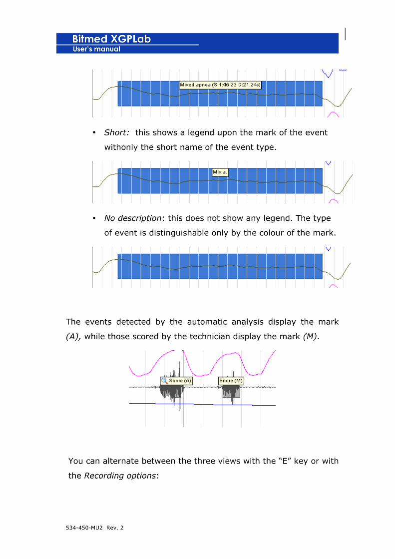
534-450-MU2 Rev. 2
• Short: this shows a legend upon the mark of the event
withonly the short name of the event type.
• No description: this does not show any legend. The type
of event is distinguishable only by the colour of the mark.
The events detected by the automatic analysis display the mark
(A), while those scored by the technician display the mark (M).
You can alternate between the three views with the “E” key or with
the Recording options:

534-450-MU2 Rev. 2
1. Open the Recording options from the menu Options >
Recording options.
2. Activate the Waves tab.
3. On the list Description of the event marks select the option you
wish to use.
4. Click on Accept to close Recording options and apply the
changes.
Automatic analysis of sleep events
! Automatic analysis of sleep events is only available if you
have acquired the corresponding licence.
The program has an option which analyzes the recording to detect
and classify events: apneas, hypopneas, desaturations, movement,
arousals, snoring and RERAs.
The criteria used are those specified in the ‘Guidelines of the Spanish
Clinical Neurophysiological Association for Polygraphic Sleep Studies
(Polysomnogram)’ published in ‘Vigil-Sleep’, no. 1/1996. Most of the
criteria can be modified by the user.
! The automatic analysis of events eliminates all of the
events marked previously in the recording.

534-450-MU2 Rev. 2
To carry out an automatic analysis of the sleep events, the following
steps should be taken:
1. Go to the menu Tools > Automatic analysis of events.
2. There will appear a window in which you must select the types
of events that you wish the program to detect. Click on Accept
when you have selected them.
3. XGPLab will warn you that you will lose the events marked in
the recording. Confirm that you wish to continue.
4. The program will begin the analysis. The events detected will be
marked on the tracing and on the event bars.
Modifying options of automatic analysis of sleep events
1. Go to the Tools menu > Settings...
2. Activate the tab Automatic analysis of events.
3. Carry out the changes you wish to make on the criteria of the
automatic analysis of events. Below is a list detailing each of
the parameters of the analysis.

534-450-MU2 Rev. 2
4. Click on Accept to apply the changes and close the Settings....
menu.
Parameters of automatic analysis of sleep events
Apnea and hypopnea:
• Minimum duration that an apnea or hypopnea must have
to be considered valid.
• Minimum percentage to which the flow must be reduced
to begin to consider it a hypopnea.
534-450-MU2 Rev. 2
• Minimum percentage to which the flow must be reduced
to begin to be considered an apnea.
• Criteria for classification of apneas as central. This is a
bar that the user can move between ‘+ strict’ and ‘-
strict’. The closer you situate the bar to ‘+ strict’, the
stricter the program will be in classifying an apnea as
central, with the result that there are fewer apneas
classified as central and more as obstructive.
• Criteria for classification of apneas as mixed. Similar to
the previous one.
• Eliminate presumably provoked apneas that coincide with
periods of artefacts.
• Channels for respiratory flow and for effort bands used for
the detection of apneas and hypopneas.
Arousal:
• Increase inactivity (in %) of the EEG signal to consider
arousal.
• Minimum duration of the change in the EEG signal to
consider arousal (in seconds).
• Duration of the sleep period that must precede arousal (in
seconds).
• Minimum separation between two arousals to be
considered as two different (in seconds).
• EEG and EMG Channels used for the detection of arousals.
RERA:

534-450-MU2 Rev. 2
• Variation of the respiratory flow signal necessary to be
considered a respiratory effort-related arousal (RERA)
(minimum and maximum value, in %).
• Minimum duration of the variation of flow to be
considered a RERA.
Desaturation:
• Decrease in the oxygen saturation after which it is
considered to be desaturation (in %).
• Minimum duration that an instance of desaturation must
have to be considered as such, in seconds.
• Maximum duration that an instance of desaturation must
have to be considered as such, in seconds.
• Ignoring abrupt falls of x% in the signal of SaO2 (for
example, to eliminate desaturations detected in the wake
of artifacts in the signal).
• Possibility of merging those desaturations which are
separated as maximum by x seconds and by an increase
in the signal of SaO2 of x%.
Movement:
• Increase in the ‘movement’ signal after which it is
considered to be movement (in %).
• Minimum duration that a movement must have to be
considered as such, in seconds.
• Maximum duration that a movement must have to be
considered as such, in seconds

534-450-MU2 Rev. 2
• Movement channels used for the detection of movements.
Snoring:
• Increase in the snoring sensor signal to be considered
snoring.
• Minimum duration of a snore (in milliseconds).
• Channel used for the detection of snores.
General parameters:
• Ignoring all of the events detected if the state of the
lights is “lights on”.
• Eliminating or not eliminating the events coinciding with
vigil.
• Eliminating or not eliminating the events coinciding with
artefacts.
Automatic spike detection
! The automatic spike detection is only available if you
have acquired the corresponding licence.
! The automatic spike analysis eliminates all of the
spikes marked previously in the recording.
To carry out an automatic spike analysis follow these steps:
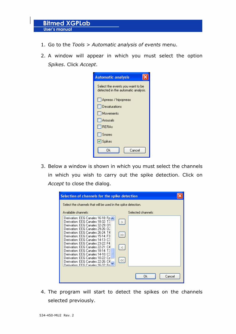
534-450-MU2 Rev. 2
1. Go to the Tools > Automatic analysis of events menu.
2. A window will appear in which you must select the option
Spikes. Click Accept.
3. Below a window is shown in which you must select the channels
in which you wish to carry out the spike detection. Click on
Accept to close the dialog.
4. The program will start to detect the spikes on the channels
selected previously.

534-450-MU2 Rev. 2
Modifying options for automatic spike detection
1. Go to the Options menu> Settings...
2. Activate the tab Automatic spike analysis.
3. Carry out the desired changes in the criteria for the automatic
spike analysis. Each of the parameters for the analysis is
detailed below.
5. Click on Accept to apply the changes and close the Settings...
menu.

534-450-MU2 Rev. 2
Parameters for automatic spike detection
• Minimum duration: Minimum duration in milliseconds that
a spike must have to be considered as such.
• Maximum duration: Maximum duration in milliseconds of
a spike to be considered as such.
• Minimum ratio of amplitude: Threshold value which
indicates the relation of amplitude of a spike with respect
to the surrounding noise.
• Ignore spikes whose amplitude is inferior to +/- uV:
minimum value of the amplitude of a spike, both positive
and negative, to be considered as such.
• Sensitivity: parameter of sensitivity of the spike
detection. A higher value in sensitivity will produce a
greater number of spikes detected, although the
processing time for the analysis will also be greater.
Reviewing spikes
1. To review the spikes detected automatically or marked by the
user, go to the See > Spikes menu.
2. Open a window with the list of spikes defined in the recording,
either detected by automatic analysis or marked by the user
themself. For each spike, the channel in which it was detected
or marked by the user is indicated, along with the starting
instant of the spike and its duration in milliseconds.
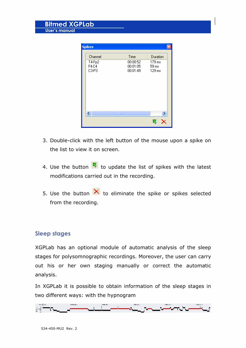
534-450-MU2 Rev. 2
3. Double-click with the left button of the mouse upon a spike on
the list to view it on screen.
4. Use the button to update the list of spikes with the latest
modifications carried out in the recording.
5. Use the button to eliminate the spike or spikes selected
from the recording.
Sleep stages
XGPLab has an optional module of automatic analysis of the sleep
stages for polysomnographic recordings. Moreover, the user can carry
out his or her own staging manually or correct the automatic
analysis.
In XGPLab it is possible to obtain information of the sleep stages in
two different ways: with the hypnogram
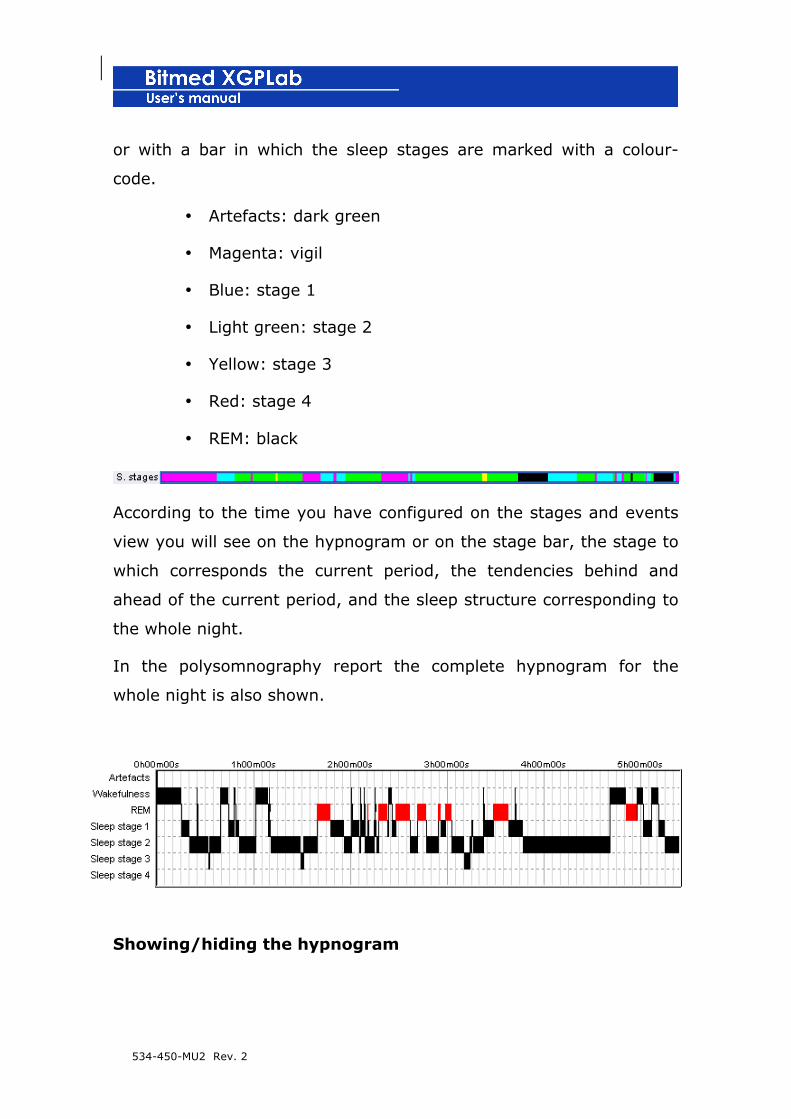
534-450-MU2 Rev. 2
or with a bar in which the sleep stages are marked with a colour-
code.
• Artefacts: dark green
• Magenta: vigil
• Blue: stage 1
• Light green: stage 2
• Yellow: stage 3
• Red: stage 4
• REM: black
According to the time you have configured on the stages and events
view you will see on the hypnogram or on the stage bar, the stage to
which corresponds the current period, the tendencies behind and
ahead of the current period, and the sleep structure corresponding to
the whole night.
In the polysomnography report the complete hypnogram for the
whole night is also shown.
Showing/hiding the hypnogram
534-450-MU2 Rev. 2
1. Open the Recording options from the menu Options >
Recording options.
2. Activate the Waves tab.
3. Activate the option See hypnogram.
4. Click on Accept to close the window and apply the changes.
Showing/hiding the stage bar
5. Open the Recording options from the menu Options >
Recording options.
6. Activate the tab Waves.
7. On the list View of the bars mark the square Lights if you wish
to show the lights bar or de-activate it if you wish to hide it.
8. Click on Accept to close the window and apply the changes.
Carrying out an automatic analysis of the sleep stages
! The automatic analysis of sleep stages is only available if
you have acquired the corresponding licence.
1. In the menu Tools select the option Automatic analysis of
stages.
2. The program will ask you to confirm that you wish to eliminate
all of the stages currently marked.
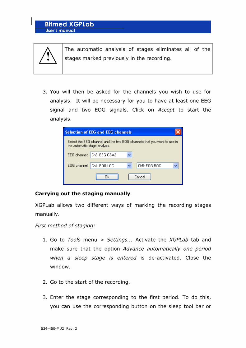
534-450-MU2 Rev. 2
! The automatic analysis of stages eliminates all of the
stages marked previously in the recording.
3. You will then be asked for the channels you wish to use for
analysis. It will be necessary for you to have at least one EEG
signal and two EOG signals. Click on Accept to start the
analysis.
Carrying out the staging manually
XGPLab allows two different ways of marking the recording stages
manually.
First method of staging:
1. Go to Tools menu > Settings... Activate the XGPLab tab and
make sure that the option Advance automatically one period
when a sleep stage is entered is de-activated. Close the
window.
2. Go to the start of the recording.
3. Enter the stage corresponding to the first period. To do this,
you can use the corresponding button on the sleep tool bar or

534-450-MU2 Rev. 2
the key associated to the stage. The software will enter a mark
from the start of the recording until the end.
4. Use the Page Up key to review all the periods until you find the
start of the next sleep stage and mark it. The new mark will
extend from the start of the current period until the end of the
recording.
5. Repeat point 4 until you reach the end of the recording.
! With this method of staging, each time you enter a sleep
stage it will be marked until the end of the recording or
until the next stage, whichever occurs first.
Second method of staging:
1. In Tools menu > Settings... activate the XGPLab tab and make
sure that the option Advance automatically one period when a
sleep stage is entered is activated. Close the window.
2. Go to the start of the recording.
3. Enter the stage corresponding to the first period. To do this,
you can use the corresponding button on the sleep tool bar or
the key associated to the stage. The software enters a mark for
that period and will automatically advance to the next period.

534-450-MU2 Rev. 2
4. Enter the sleep stage corresponding to the period on screen.
The software will go automatically to the next period.
5. Repeat point 4 until you reach the end of the recording.
! In this method of staging each time a sleep stage is
entered, the stage will be marked only in the period in
which it is found. Moreover, the software will move
automatically to the next period.
Event summary panel
XGPLab provides an event summary window where you will find all
the information you need on the events marked, sleep stages, lights
status and notes introduced in the recording.

534-450-MU2 Rev. 2
Opening event summary panel
1. Click on the Event Summary Panel button or on the View menu >
See Summary panel.
2. The Event Summary Panel will open.
3. Active the elements to display in the window: Events (you can
filter the types of events to be displayed), Sleep stages, State of
lights and Notes.
Surfing the events
Double click on the event desired or use the buttons <<, <, >,>> to
select the first, the previous, the next or the last element of the list.
Deleting events
Select the event(s) from the list and press the Delete key of the
keyboard. It(they) will be eliminated from the list and from the
recording.
Playing back the recording
Any recording can be played back automatically at different speeds.
To Follor these steps:
1. Move into the part of the recording from which you play back.
You can choose the beginning or any other moment of the
recording.
2. Click on the Start button to play back the recording.
3. The recording will start playing back, as it was recorded. If you
want multiply by two the playback speed click the button x2
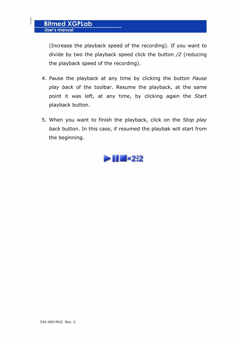
534-450-MU2 Rev. 2
(Increase the playback speed of the recording). If you want to
divide by two the playback speed click the button /2 (reducing
the playback speed of the recording).
4. Pause the playback at any time by clicking the button Pause
play back of the toolbar. Resume the playback, at the same
point it was left, at any time, by clicking again the Start
playback button.
5. When you want to finish the playback, click on the Stop play
back button. In this case, if resumed the playbak will start from
the beginning.
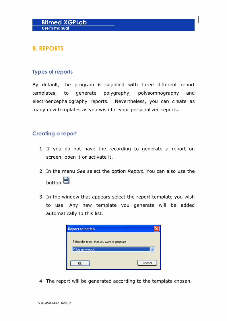
534-450-MU2 Rev. 2
8. REPORTS
Types of reports
By default, the program is supplied with three different report
templates, to generate polygraphy, polysomnography and
electroencephalography reports. Nevertheless, you can create as
many new templates as you wish for your personalized reports.
Creating a report
1. If you do not have the recording to generate a report on
screen, open it or activate it.
2. In the menu See select the option Report. You can also use the
button .
3. In the window that appears select the report template you wish
to use. Any new template you generate will be added
automatically to this list.
4. The report will be generated according to the template chosen.
534-450-MU2 Rev. 2
! In a polysomnography report, to correctly calculate the
hypnogram and the statistics relating to sleep, the user
must have previously analyzed the sleep stages of the
recording, as well as marking the state of the lights; and
in order for all the information concerning events to
appear correctly, it is imperative that all the analysis has
been carried out either manually or automatically. In the
event of there being no defined stages, the analysis
module will distinguish the vigil/dream states on the basis
of the state of the lights.
! If the recording is edited after the report has been
generated, it will be necessary to generate it again for
the changes to appear.
Creating and modifying report template
The report templates are found in the folder Templates in the folder
where the XGPLab has been installed (for example: C:/Program
Files/Bitmed/XGPLab _.__/Templates).
The report templates are in RTF format. RTF is a type of universal file
for text formatting. The Windows program Write supplied together
with Windows or MS Word, to name only two common programs, are
capable of working with this type of file.
Any template that is saved in this folder will appear as a selectable
template in the Selection of report type window. You only have to
534-450-MU2 Rev. 2
create a new template and save it in the Templates folder so that it
will be available to generate a new report.
The use of the report templates is based on a series of labels which
are later interpreted by the XPGLab software to generate the reports.
For example, if a line of a template is:
Name: #name_pac#
The program will substitute the label #name_pat.# for the real name
of the patient, so that in the report, this will appear:
Name: Nuria Pino Torres
If, however, the template shows:
Total Time of recording: #TRT# min
in the report generated the label #TRT# will be substituted for the
total time of recording:
Total Time of recording: 182 min
Using your usual word processor, you can open any of the report
templates supplied by default with the program to check the
appearance of a report template.
534-450-MU2 Rev. 2
Consult Annex I to see the complete list of available labels to
personalize your reports.
To summarize, the steps to create a report template are as follows:
1. Open a word processor, such as Windows Write or MS Word.
2. Create a new document or any of the report templates existing
in the Templates folder.
3. Personalize the report as you like. You can use tables, text
formatting (bold type, different types of font, colours), images…
The text you write will appear as such in the report, while the
labels with the format #name_label# will be substituted by a
value calculated by the program.
4. When you have finished, save the file with the extension .RTF in
the Templates folder.
5. The new template will appear thereafter in the list of available
templates to generate reports.

534-450-MU2 Rev. 2
Opening an existing report
1. Go to the menu File > Open.
2. In the Open window select the option Report files (*.rtf)from
the Type list.
3. Search for the report you wish to open, select and open it by
clicking on Open.
Printing a report
1. With the report open and active on screen, go to the menu File
> Print.
2. Select the printer, its properties, the printing interval and the
number of copies required.
3. Click on Accept to start printing.
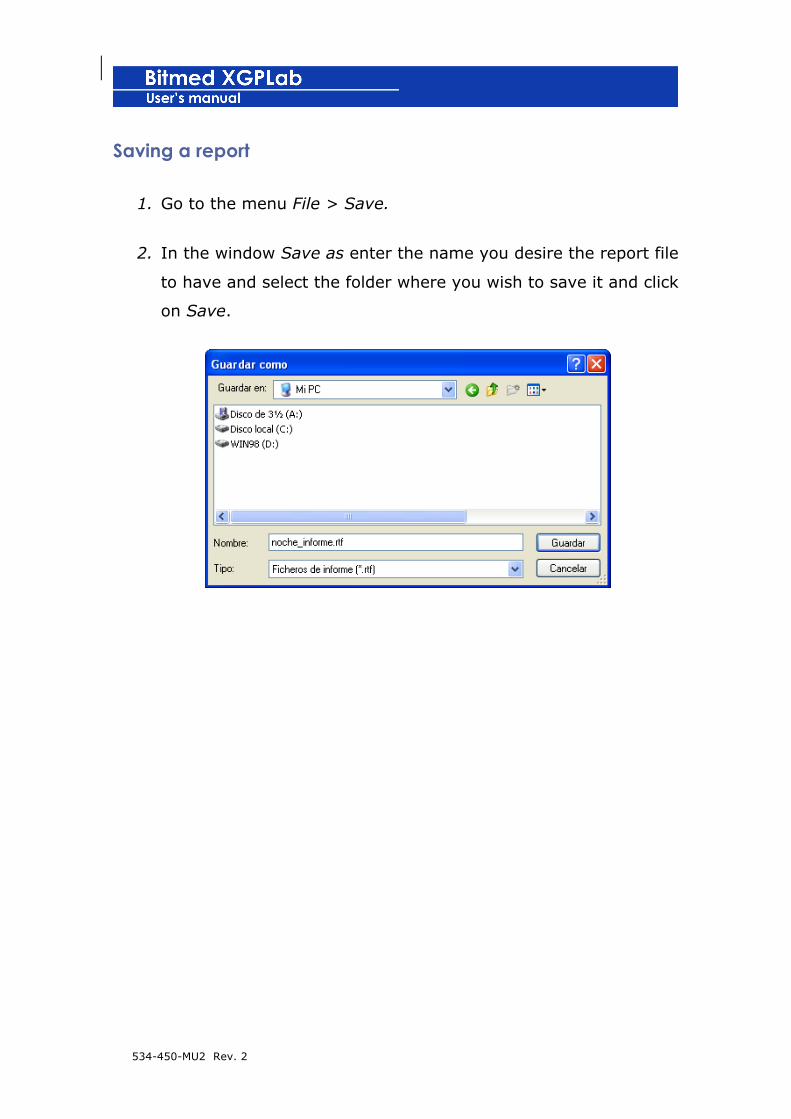
534-450-MU2 Rev. 2
Saving a report
1. Go to the menu File > Save.
2. In the window Save as enter the name you desire the report file
to have and select the folder where you wish to save it and click
on Save.

534-450-MU2 Rev. 2
9. ACQUISITION OF DIGITAL VIDEO: XGPVISION
XGPVision is an optional module permitting the acquisition of
synchronized digital video and audio for making EEG video and the
monitoring of sleep studies.
The audio and video are saved in a file that is different from the
recording file, although in the same folder and with the same name,
with extension .AVI. The acquisition of video is a time-consuming
process for the computer, thus, during capture, the compression
made of the video is minimal. This produces large files (they can
weigh several gigabytes), therefore they need to be compressed after
acquisition. The compression made in the case of the video uses a
standard MPEG4 compressor, which significantly reduces the size of
the file. For the audio a compressor based on the standard MP3 is
used. The compression achieves a significant reduction in the size of
the file, without its quality suffering.
XGPVision integrates totally in XGPLab and is very simple to use.
! The functions included throughout this chapter are only
available if you have acquired an XGPVision licence.
Requirements for capturing video
Meditel Medial Engineering recommends a computer equipped with an
Intel Pentium 4, Athlon XP, Athlon 64 or superior processor to carry
out the capture of the video. The hard disk must have several

534-450-MU2 Rev. 2
gigabytes of free space in case long-term sleep studies or EEG
monitoring are performed.
If a desktop computer is used, it should have a PCI slot free for the
capture card. In the case of laptop computers, the card is available in
PCMCIA format.
Any model of capture card compatible with DirectX is sufficient to
carry out the acquisition. Nevertheless, Meditel Medical Engineering
has modules of proven efficiency which ensure a minimal intervention
on the part of the CPU of the computer and guarantee the absence of
lags between the real image and capture.
Capturing video with the recording
1. Begin the new recording in real time. When you are in the
window of the Recording options activate the Video tab.

534-450-MU2 Rev. 2
2. Activate the option Acquire video and from the list Video
capture devices select the name of the video capture cards.
This list includes all of the devices installed in the system
capable of capturing video.
3. If you also wish to acquire audio, activate the Acquire audio
square. As in the preceding point, select the audio capture
device from the corresponding list.
4. Activate the option Ask me for the file name before starting the
recording if you want the program to ask you for a name for
the file the video will store at the start of the recording.
Otherwise, the video file will take the same name as that of the
recording, but with extension .AVI, and will be saved in the
same folder.
5. You can use the Preview option to obtain a preview in the
Preview window of the currently selected video source.
6. Click on Accept and start the recording and the capture of the
video.
7. In the upper right-hand part of the screen will be shown the
video view window, which is acquired at the same time as the
data for the signals.
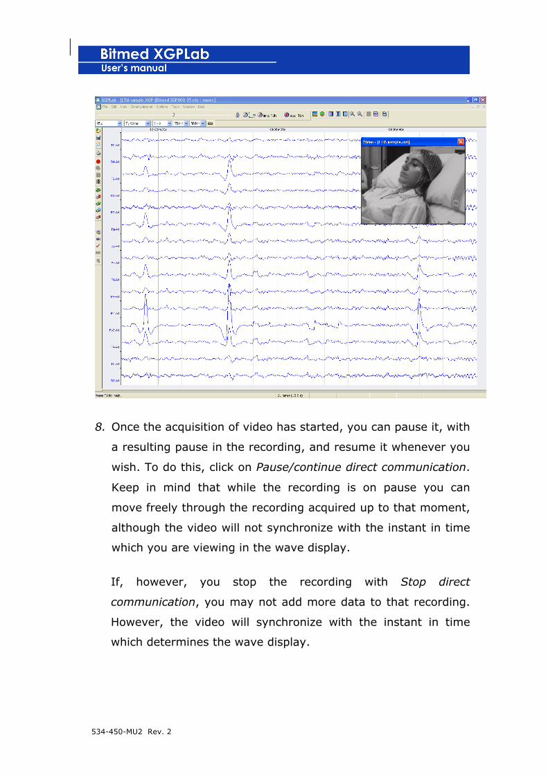
534-450-MU2 Rev. 2
8. Once the acquisition of video has started, you can pause it, with
a resulting pause in the recording, and resume it whenever you
wish. To do this, click on Pause/continue direct communication.
Keep in mind that while the recording is on pause you can
move freely through the recording acquired up to that moment,
although the video will not synchronize with the instant in time
which you are viewing in the wave display.
If, however, you stop the recording with Stop direct
communication, you may not add more data to that recording.
However, the video will synchronize with the instant in time
which determines the wave display.
534-450-MU2 Rev. 2
Modifying capturing properties
From the Video tab of the Recording options you can modify the
properties of the capture of audio and video.
! It is only possible to modify the properties of the capture
before starting the recording.
Photograms per second: number of video photograms which will be
captured per second. Take into account that a high rate will cause the
size of the video file to grow much larger; for long recordings, this
can be several gigabytes. For example, a 9-hour video recording
compressed at a rate of 5 frames/second takes up about 600
Megabytes.
Controls: these allow the modification of the card capture properties
(brightness, contrast, saturation ...). Select the input font, the type of
input signal (camera, video). The properties available depend on
which model of capture card the system has. It is possible that some
of the options mentioned might appear in another menu. Normally
the correct values are Composite video and PAL System.

534-450-MU2 Rev. 2
Format: this allows you to establish the size of the capture window,
the format of the images to be recorded... If you have a Winnov
Videum 1000 Plus card, we recommend using the Hardware
compression format with a window size 320x240, selecting the
quality of the compression at will. If you do not have the Winnov
Videum 1000 Plus card a possible configuration might be with a
similar size of window but using the 24-bit RGB image format.
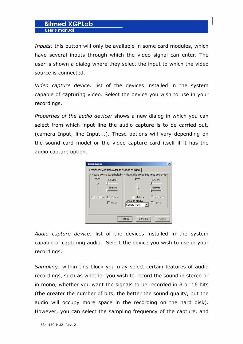
534-450-MU2 Rev. 2
Inputs: this button will only be available in some card modules, which
have several inputs through which the video signal can enter. The
user is shown a dialog where they select the input to which the video
source is connected.
Video capture device: list of the devices installed in the system
capable of capturing video. Select the device you wish to use in your
recordings.
Properties of the audio device: shows a new dialog in which you can
select from which input line the audio capture is to be carried out.
(camera Input, line Input...). These options will vary depending on
the sound card model or the video capture card itself if it has the
audio capture option.
Audio capture device: list of the devices installed in the system
capable of capturing audio. Select the device you wish to use in your
recordings.
Sampling: within this block you may select certain features of audio
recordings, such as whether you wish to record the sound in stereo or
in mono, whether you want the signals to be recorded in 8 or 16 bits
(the greater the number of bits, the better the sound quality, but the
audio will occupy more space in the recording on the hard disk).
However, you can select the sampling frequency of the capture, and

534-450-MU2 Rev. 2
may select between 11, 22 or 44 KHz. The higher the frequency, the
greater the size of the resulting file.
Reviewing the recording together with the video
When you finish making a recording with video, or open a recording
with vide, the video window is in the upper right-hand part of the
main window of XGPLab.
You can hide the window by clicking on the button with the cross and
have it displayed again from the See > Video menu.
If the cursor for numerical data is active you can check how the video
window shows the photogram corresponding to the instant in time
where the cursor is situated.

534-450-MU2 Rev. 2
If it is not active, the video window will show the photogram
corresponding to the left end of the wave display or to the position of
the pointer if you are making a selection on the recording.
! If you eliminate a part of the recording the corresponding
part of the video will not be deleted, and therefore it will
no longer be synchronized with the wave recording.
Compressing video file automatically when recording stops
If you want the program to automatically compress the video and the
audio once the communication has stopped, select the option
Compress video on finishing the recording on the Video tab of the
Recording options. Nevertheless, the program will ask you for
confirmation before carrying out the operation, as it is a laborious
process which can take time in the case of long recordings.
Compressing video file from XGPLab
1. Open the recording whose associated video file you wish to
compress.
2. Open the Recording options from Options > Recording options.
3. Activate the Video tab.
4. Start the video compressor by clicking on the button Compress
Video now.

534-450-MU2 Rev. 2
5. The dialog AV Compression will open, in which you can select
the file to compress (by default this is the one associated with
the active recording) and the name of the already-compressed
file. Click on Accept to start the compression process.
Compressing a video file from AV compression tool
1. In the Windows Start menu go to All programs > Bitmed and
open the AV Compression program.
2. Select in Input file the video file you wish to compress.

534-450-MU2 Rev. 2
3. Select in Output file the name you wish to give to the
compressed video file. You can select the file itself, if you wish.
4. Click on Compress to start the compression.
Changing video file associated to a recording
This option only appears once the acquisition of the recording has
finished and allows a video file other than the original to be
associated to the recording. This is useful when a recording from a
folder or computer and the location of the video file associated with
the recording does not coincide with the original.
1. Open the Recording options from Options > Recording options.
2. Activate Video the tab.
3. Click on the button Video file associated to the recording to
select the video file you wish to associate to the recording.
4. Click on Accept to close the Recording options and apply the
changes.
534-450-MU2 Rev. 2
10. FREQUENTIAL ANALYSIS
The optional module for frequential analysis provides you with two
working tools based on the Fast Fourier Transform (FFT): the
spectrum of frequencies (also called spectral density) and the view of
power/frequency/time.
! The functions included throughout this chapter are only
available if you have acquired a frequential analysis
licence.
Spectrum of frequencies
The spectrum of frequencies shows the frequency content of the
selection in a specific channel with a graph.
1. In the Wave display select the range of the recording from
which you wish to obtain the spectrum of frequencies.
2. The contextual menu of the selection will appear. Click on
Spectrum of frequencies.
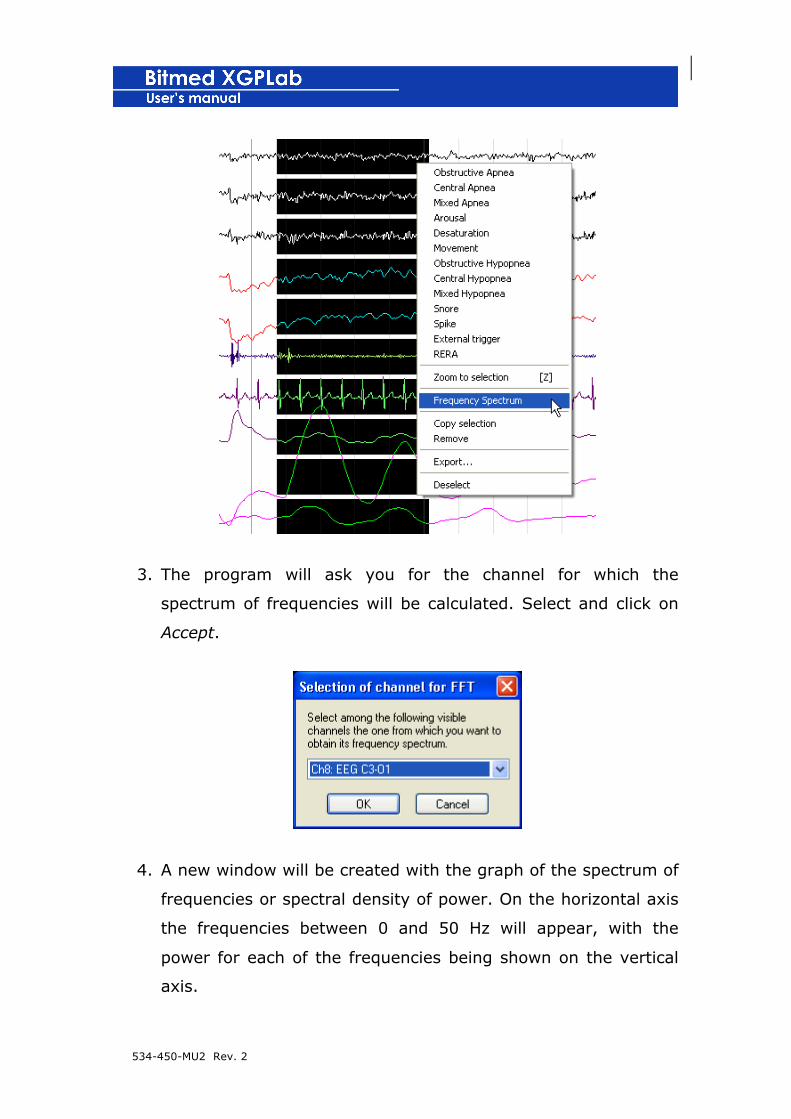
534-450-MU2 Rev. 2
3. The program will ask you for the channel for which the
spectrum of frequencies will be calculated. Select and click on
Accept.
4. A new window will be created with the graph of the spectrum of
frequencies or spectral density of power. On the horizontal axis
the frequencies between 0 and 50 Hz will appear, with the
power for each of the frequencies being shown on the vertical
axis.
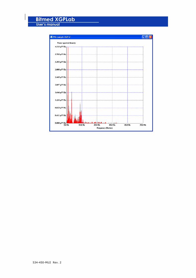
534-450-MU2 Rev. 2

534-450-MU2 Rev. 2
Changing the scale of frequencies
1. Right-Click anywhere in the graph and select Properties option.
2. On the Properties window of the graph select the range of
frequencies to display and press Accept to implement the
changes.
Printing spectrum of frequencies
1. Ensure that the window of the spectrum of frequencies is active
and go to File > Print.
2. Select the printer, its properties, the printing interval and the
number of copies required.
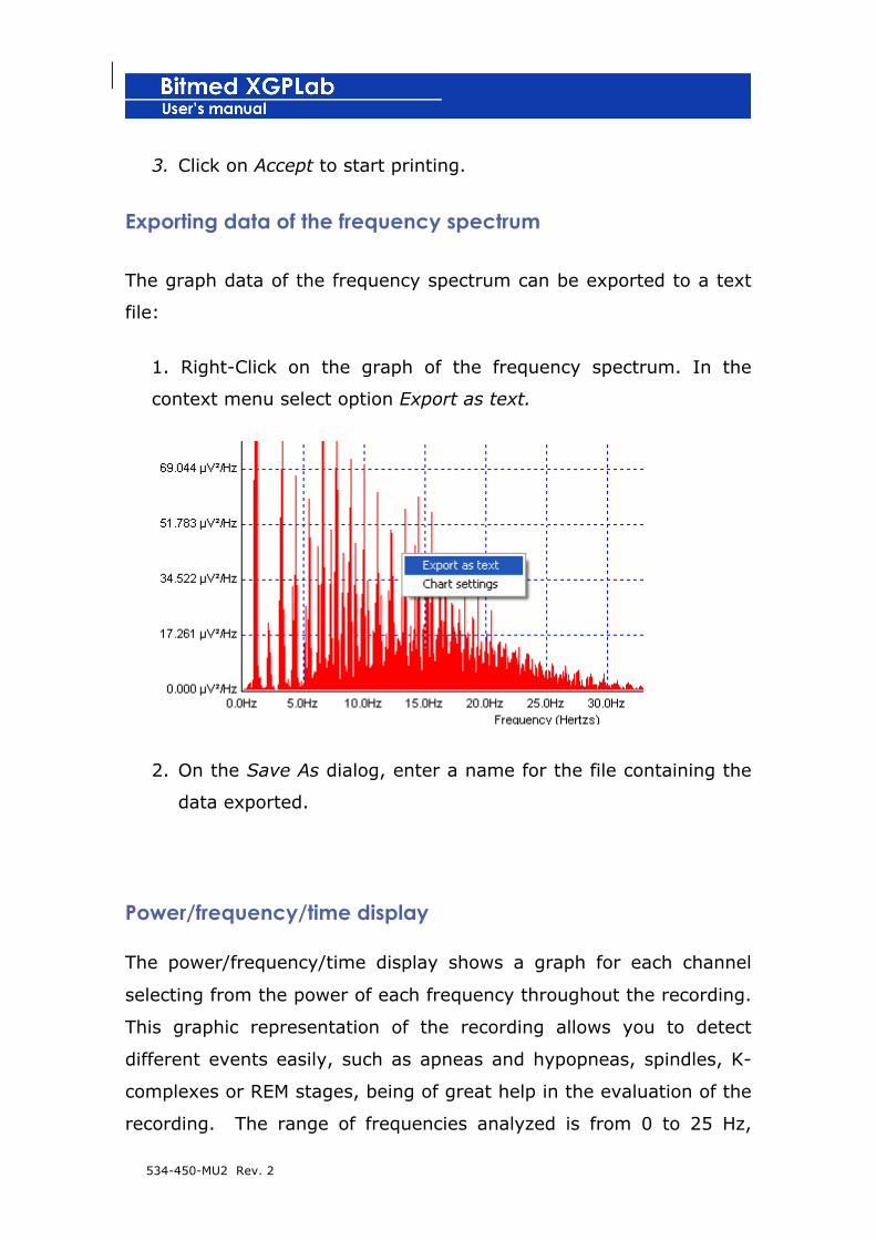
534-450-MU2 Rev. 2
3. Click on Accept to start printing.
Exporting data of the frequency spectrum
The graph data of the frequency spectrum can be exported to a text
file:
1. Right-Click on the graph of the frequency spectrum. In the
context menu select option Export as text.
2. On the Save As dialog, enter a name for the file containing the
data exported.
Power/frequency/time display
The power/frequency/time display shows a graph for each channel
selecting from the power of each frequency throughout the recording.
This graphic representation of the recording allows you to detect
different events easily, such as apneas and hypopneas, spindles, K-
complexes or REM stages, being of great help in the evaluation of the
recording. The range of frequencies analyzed is from 0 to 25 Hz,
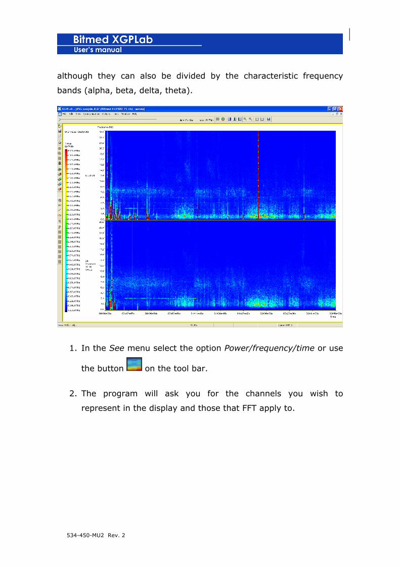
534-450-MU2 Rev. 2
although they can also be divided by the characteristic frequency
bands (alpha, beta, delta, theta).
1. In the See menu select the option Power/frequency/time or use
the button on the tool bar.
2. The program will ask you for the channels you wish to
represent in the display and those that FFT apply to.

534-450-MU2 Rev. 2
3. After calculation of the FFT, the Power/frequency/time display
will be shown. If you are positioned upon any point of the graph
and press the right button of the mouse you will obtain the
corresponding power for the channel, frequency and instant of
time in which the cursor is situated.
Modifying colour scale
By default the program automatically adjusts the colour scale, taking
into account the highest power value found. Nevertheless it is very
easy to modify the colour scale.

534-450-MU2 Rev. 2
1. Click on the colour scale with the right button of the mouse.
On the menu which appears select the option Colour palette
options.
2. In the window Colour palette options select the maximum and
minimum values you wish for the scale of the graph. Click on
Accept to apply the changes.
Showing frequencies grouped by frequency bands.
1. Open the Recording options from the menu Options >
Recording options.
2. Activate the tab Power/Frequency/time.
3. Activate the option See frequency bands.

534-450-MU2 Rev. 2
4. Click on Accept to close the Recording options and apply the
changes.
Printing power/frequency/time display
1. Go to the menu File > Print.
2. Select the printer, its properties, the printing interval and the
number of copies required.
3. Click on Accept to begin the printing.

534-450-MU2 Rev. 2
11. CEREBRAL CARTOGRAPHY
The optional module of cerebral cartography transforms the
electroencephalographic signals into information on cerebral activity,
especially representing the power contained in each frequency.
! The functions included throughout this chapter are only
available if you have acquired the cerebral cartography
licence.
Power/frequency map
The power/frequency map is the graphic representation of cerebral
cartography. It is an overhead representation of the head of the
subject upon which 10-20 standard electrodes are shown and the
power contained in each point for the frequency selected, with a
colour scale. On the right-hand side a graph is shown corresponding
to the power contained in each frequency for each channel. The data
are calculated in periods of 30 seconds. The time bar is used to up-
date the power/frequency map with the activity of one instant of
specific time.
1. In the See menu select the option Power/frequency map or
click on the button on the tool bar.
2. The program will ask you for the electrodes you wish to
represent on the map and those which apply to the FFT.

534-450-MU2 Rev. 2
3. After the calculation of the FFT, that of the power/frequency
map will be shown.
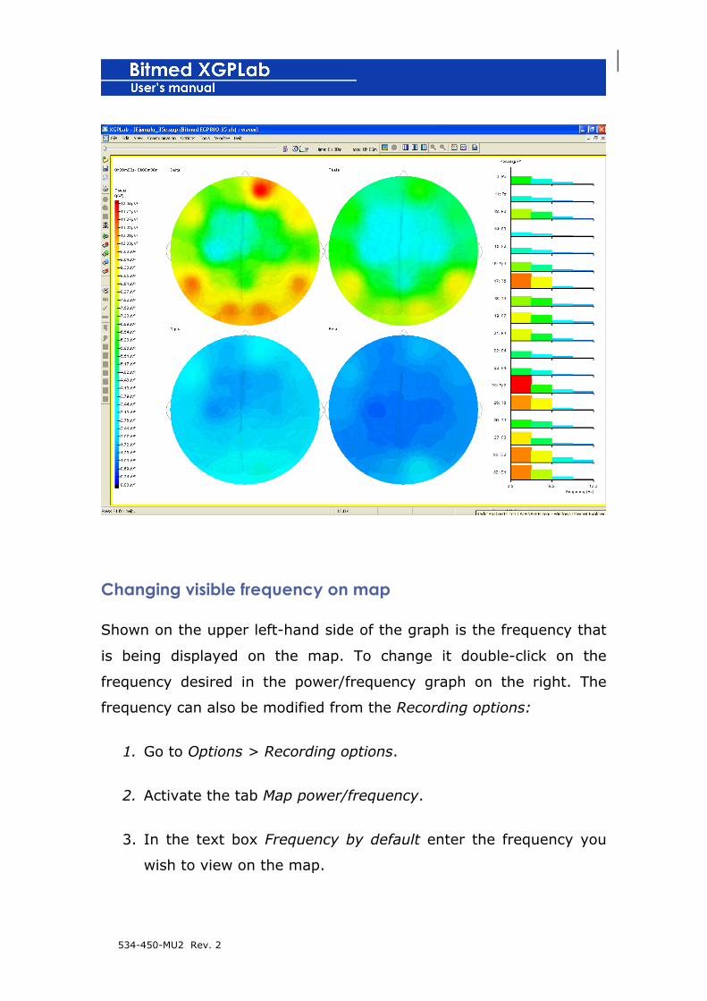
534-450-MU2 Rev. 2
Changing visible frequency on map
Shown on the upper left-hand side of the graph is the frequency that
is being displayed on the map. To change it double-click on the
frequency desired in the power/frequency graph on the right. The
frequency can also be modified from the Recording options:
1. Go to Options > Recording options.
2. Activate the tab Map power/frequency.
3. In the text box Frequency by default enter the frequency you
wish to view on the map.

534-450-MU2 Rev. 2
4. Click on Accept to apply the changes.
Modifying options of power/frequency map
1. Open the Recording options from the Options > Recording
options menu.
2. Activate the Power/frequency map tab.
3. Activate the option See frequency bands to group the
frequencies on the characteristic bands: alpha, beta, delta,
theta.
4. Activate the option See background image to show an image of
the brain in the heads of the map.
5. Use the option See placement of the electrodes to show or hide
the names and the position of the electrodes selected on the
view of the map.
6. Click on Accept to close the Recording options and apply the
changes.

534-450-MU2 Rev. 2

534-450-MU2 Rev. 2
12. TROUBLE-SHOOTING
When the program is loaded, you cannot find the software
licence
- Check that the hardlock is correctly connected to the parallel port
in the manner explained in section 2, Installation guide.
- Although the installation of the software includes the drivers for
the hardlock, there could be a problem with the location of the
files and their recording in the system. Re-install the drivers from
the CD by running the file hldrv32.exe. Follow the steps on
screen until the installation is finished.
The program does not communicate with the unit
- Check that the unit is connected and working.
- Check the connections and that these are firm.
- Make sure to connect the unit to the appropriate port of the
computer.

534-450-MU2 Rev. 2
ANNEX 1
LABELS AVAILABLE FOR CREATION OR MODIFICATION
OF TEMPLATES
Data of the user
#name_usr# Name of the user
#address_usr# Address of the user
#locality_usr# Locality of the user
#pc_usr# Postal code of the use
#telephone_usr# Telephone no. of the user
#logo_usr# Image of the user’s logo
Data of the patient
This data is taken from the window Recording data.
#name_pac# Name of the patient
#surname1_pac# First surname of the patient
#surname2_pac# Second surname of the patient
#age_pac# Age of the patient
#height_pac# Height of the patient
#weight_pac# Weight of the patient
#b_m_i# Body mass index of the patient
#address_pac# Address of the patient

534-450-MU2 Rev. 2
#city_pac# City of the patient
#province_pac# Province of the patient
#telephone_pac# Telephone of the patient
#sex_pat# Sex of the patient
Recording Data
This data is taken from the window Recording Data.
#file_recording# Name of the recording from which the report has been
generated
#date_recording# Date of creation of recording
#start_time_recording# Start time of recording
#fin_time_recording# Finishing time of recording
#doctor_reference# Name of doctor requesting the test
#technician_recording# Name of technician in charge of making the
recording.
#model_unit# Model of the Bitmed unit with which the unit has been made.
Sleep data
#graphic_stages# Histogram of the sleep stages throughout the recording
#parameters_a_a_f# List of criteria used in the automatic analysis of
stages
#TRT# Total recording time, in minutes

534-450-MU2 Rev. 2
#TIB# Total darkness time (time in bed)
#SPT# Sleep period time
#TST# Total sleep time
#efficiency_sleep# Efficiency of sleep
#efficacy_sleep# Efficacy of sleep
#number_wakeups# Total number of wakeups
#latency_start_sleep# Latency on starting sleep, in minutes
#lat_rem# Latency to the first REM episode from the start of the recording,
in minutes
#lat_nrem# Latency to the first sleep stage NREM from the start of the
recording, in minutes
#number_changes_stage# Total number of stage changes
#number_episodes_rem# Total number of changes to REM stage
#fragmentation_dream# Dream fragmentation index
#first_stage_dream# Name of the first sleep stage which appears in the
recording
#WASO# Wake time After Sleep Onset, in minutes. Interspersed vigil.
#WAFA# Wake time After Final Awakening, in minutes
#instant_lights_off# Time the lights were turned off
#instant_lights_on# Time the lights were turned on
#t_t_a# Total time of artefacts
#t_t_v# Total time in vigil
#t_t_r# Total time in REM
#t_t_f1# Total time in Stage 1

534-450-MU2 Rev. 2
#t_t_f2# Total time in Stage 2
#t_t_f3# Total time in Stage 3
#t_t_f4# Total time in Stage 4
#%_TIB_a# Percentage of artefacts on the TIB
#%_TIB_v# Percentage of vigil on the TIB
#%_TIB_r# Percentage of REM on the TIB
#%_TIB_ph1# Percentage of Stage 1 on the TIB
#%_TIB_ph2# Percentage of Stage 2 on the TIB
#%_TIB_ph3# Percentage of Stage 3 on the TIB
#%_TIB_ph4# Percentage of Stage 4 on the TIB
#%_SPT_a# Percentage of artefacts on the SPT
#%_SPT_v# Percentage of vigil on the SPT
#%_SPT_r# Percentage of REM on the SPT
#%_SPT_ph1# Percentage of Stage 1 on the SPT
#%_SPT_ph2# Percentage of Stage 2 on the SPT
#%_SPT_ph3# Percentage of Stage 3 on the SPT
#%_SPT_ph4# Percentage of Stage 4 on the SPT
#%_TST_r# Percentage of REM on the TST
#%_TST_ph1# Percentage of Stage 1 on the TST
#%_TST_ph2# Percentage of Stage 2 on the TST
#%_TST_ph3# Percentage of Stage 3 on the TST
#%_TST_ph4# Percentage of Stage 4 on the TST
#%_TST_artef# Percentage of time of artefacts on the TST

534-450-MU2 Rev. 2
#%_TST_ph3_ph4_r# Percentage of time in stage 3, stage 4 or REM on the
TST
#%_l_l_to_r# Latency to REM from lights turned off
#%_l_l_to_ph1# Latency to Stage 1 from lights turned off
#%_l_l_to_ph2# Latency to Stage 2 from lights turned off
#%_l_l_to_ph3# Latency to Stage 3 from lights turned off
#%_l_l_to_ph4# Latency to Stage 4 from lights turned off
#%_l_i_s_r# Latency to REM from the start of sleep
#%_l_i_s_ph1# Latency to Stage 1 from the start of sleep
#%_l_i_s_ph2# Latency to Stage 2 from the start of sleep
#%_l_i_s_ph3# Latency to Stage 3 from the start of sleep
#%_l_i_s_ph4# Latency to Stage 4 from the start of sleep
#t_ver# Past time in vertical position
#t_left# Past time in decubitus left side
#t_arr# Past time in decubitus supine
#t_ab# Past time in decubitus prone
#t_right# Past time in decubitus right side
#%_TST_ver# Percentage of time on the TST in which the patient is in
vertical position
#%_TST_left# Percentage of time on the TST in which the patient is in
decubitus left side
#%_TST_arr# Percentage of time on the TST in which the patient is in
decubitus supine
#%_TST_ab# Percentage of time on the TST in which the patient is in
decubitus prone

534-450-MU2 Rev. 2
#%_TST_der# Percentage of time on the TST in which the patient is in
decubitus right side
Data of Events
#scale_temporary# Draws a temporary scale which supplements the
graphs of the events.
#graph_a# Summary graph of apneas. Each type of apnea is distinguished
by a different colour. The length of the mark of each event is proportional
to the duration of the event.
#graph_h# Summary graph of hypopneas. Does not make a distinction
between types of hypopneas. The length of the mark of each event is
proportional to the duration of the event.
#graph_h_d# Summary graph of hypopneas. Each type of hypopnea is
distinguishable by a different colour. The length of the mark of each event is
proportional to the duration of the event.
#graph_oa# Summary graph of obstructive apneas. The length of the mark
of each event is proportional to the duration of the event.
#graph_ca# Summary graph of central apneas. The length of the mark of
each event is proportional to the duration of the event.
#graph_ma# Summary graph of mixed apneas. The length of the mark of
each event is proportional to the duration of the event.
#graph_aro# Summary graph of arousals. The length of the mark of each
event is proportional to the duration of the event.
#graph_des# Summary graph of desaturations. The length of the mark of
each event is proportional to the duration of the event.
#graph_mov# Summary graph of movements. The length of the mark of
each event is proportional to the duration of the event.

534-450-MU2 Rev. 2
#graph_ho# Summary graph of obstructive hypopneas. The length of the
mark of each event is proportional to the duration of the event.
#graph_hc# Summary graph of central hypopneas. The length of the mark
of each event is proportional to the duration of the event.
#graph_hm# Summary graph of mixed hypopneas. The length of the mark
of each event is proportional to the duration of the event.
#graph_ron# Summary graph of snores. The length of the mark of each
event is proportional to the duration of the event.
#graph_pta# Summary graph of spikes. The length of the mark of each
event is proportional to the duration of the event.
#graph_fls# Summary graph of the events of the external triggers
generator. The length of the mark of each event is proportional to the
duration of the event.
#graph_rera# Summary graph of the RERAs. The length of the mark of
each event is proportional to the duration of the event.
#graph_lf# Summary graph of the flow limitations. The length of the mark
of each event is proportional to the duration of the event.
#graph_arom# Summary graph of arousals caused by movements. The
length of the mark of each event is proportional to the duration of the
event.
#graph_eu1# Summary graph of the occurrences of the first type of event
defined by the user. The length of the mark of each event is proportional to
the duration of the event.
#graph_eu2# Summary graph of the occurrences of the second type of
event defined by the user. The length of the mark of each event is
proportional to the duration of the event.

534-450-MU2 Rev. 2
#graph_eu3# Summary graph of the occurrences of the third type of event
defined by the user. The length of the mark of each event is proportional to
the duration of the event.
#graph_eu4# Summary graph of the occurrences of the fourth type of
event defined by the user. The length of the mark of each event is
proportional to the duration of the event.
#graph_eu5# Summary graph of the occurrences of the fifth type of event
defined by the user. The length of the mark of each event is proportional to
the duration of the event.
#graph_eu6# Summary graph of the occurrences of the sixth type of event
defined by the user. The length of the mark of each event is proportional to
the duration of the event.
#graph_eu7# Summary graph of the occurrences of the seventh type of
event defined by the user. The length of the mark of each event is
proportional to the duration of the event.
#graph_eu8# Summary graph of the occurrences of the eighth type of
event defined by the user. The length of the mark of each event is
proportional to the duration of the event.
#graph_eu9# Summary graph of the occurrences of the ninth type of event
defined by the user. The length of the mark of each event is proportional to
the duration of the event.
#graph_eu10# Summary graph of the occurrences of the tenth type of
event defined by the user. The length of the mark of each event is
proportional to the duration of the event.
#graphic_events# Graph with the events marked throughout the recording.
Shows on a single graph the information of all of the types of events.
#parameters_a_a_e# List of criteria used in the automatic analysis of
events
#total_a# Total number of apneas
534-450-MU2 Rev. 2
#total_h# Total number of hypopneas
#total_a_h# Total number of apneas and hypopneas
#total_a_h_o# Total number of obstructive apneas and hypopneas
#total_a_h_c# Total number of apneas and central hypopneas
#total_a_h_m# Total number of apneas and mixed hypopneas
#total_ao# Total number of obstructive apneas
#total_ac# Total number of central apneas
#total_am# Total number of mixed apneas
#total_aro# Total number of arousals
#total_des# Total number of desaturations
#total_mov# Total number of movements
#total_ho# Total number of obstructive hypopneas
#total_hc# Total number of obstructive hypopneas
#total_hm# Total number of obstructive hypopneas
#total_snores# Total number of snores
#total_spikes# Total number of spikes
#total_fls# Total number of external triggers
#total_RERA# Total number of RERAs
#total_lf# Total number of flow limitations
#total_arom# Total number of arousals caused by movements
#total_eu1# Total number of occurrences of the first event defined by the
user
#total_eu2# Total number of occurrences of the second event defined by
the user

534-450-MU2 Rev. 2
#total_eu3# Total number of occurrences of the third event defined by the
user
#total_eu4# Total number of occurrences of the fourth event defined by the
user
#total_eu5# Total number of occurrences of the fifth event defined by the
user
#total_eu6# Total number of occurrences of the sixth event defined by the
user
#total_eu7# Total number of occurrences of the seventh event defined by
the user
#total_eu8# Total number of occurrences of the eighth event defined by
the user
#total_eu9# Total number of occurrences of the ninth event defined by the
user
#total_eu10# Total number of occurrences of the tenth event defined by
the user
#ihs_ao# Sleep time index of obstructive apneas
#ihs_ac# Sleep time index of central apneas
#ihs_am# Sleep time index of mixed apneas
#ihs_aro# Sleep time index of arousals
#ihs_des Sleep time index of desaturations
#ihs_mov# Sleep time index of movements
#ihs_ho# Sleep time index of obstructive hypopneas
#ihs_hc# Sleep time index of central hypopneas
#ihs_hm# Sleep time index of mixed hypopneas
534-450-MU2 Rev. 2
#ihs_ron# Sleep time index of snores
#ihs_pta# Sleep time index of spikes
#ihs_fls# Sleep time index of external triggers
#ihs_RERA# Sleep time index of RERAs
#ihs_lf# Sleep time index of flow limitations
#ihs_arom# Sleep time index of arousals caused by movements
#ihs_eu1# Sleep time index of first event defined by the user
#ihs_eu2# Sleep time index of second event defined by the user
#ihs_eu3# Sleep time index of third event defined by the user
#ihs_eu4# Sleep time index of fourth event defined by the user
#ihs_eu5# Sleep time index of fifth event defined by the user
#ihs_eu6# Sleep time index of sixth event defined by the user
#ihs_eu7# Sleep time index of seventh event defined by the user
#ihs_eu8# Sleep time index of eighth event defined by the user
#ihs_eu9# Sleep time index of ninth event defined by the user
#ihs_eu10# Sleep time index of tenth event defined by the user
#d_t_a_h# Total duration of apneas and hypopneas
#d_t_ao# Total duration of obstructive apneas
#d_t_ac# Total duration of central apneas
#d_t_am# Total duration of mixed apneas
#d_t_aro# Total duration of arousals
#d_t_des# Total duration of desaturations
#d_t_mov# Total duration of movements

534-450-MU2 Rev. 2
#d_t_ho# Total duration of obstructive obstructive hypopneas
#d_t_hc# Total duration of central hypopneas
#d_t_hm# Total duration of mixed hypopneas
#d_t_ron# Total duration of snores
#d_t_pta# Total duration of spikes
#d_t_fls# Total duration of external triggers
#d_t_lf# Total duration of flow limitations
#d_t_arom# Total duration of arousals caused by movements
#d_t_eu1# Total duration of occurrences of the first event defined by the
user
#d_t_eu2# Total duration of occurrences of the second event defined by
the user
#d_t_eu3# Total duration of occurrences of the third event defined by the
user
#d_t_eu4# Total duration of occurrences of the fourth event defined by the
user
#d_t_eu5# Total duration of occurrences of the fifth event defined by the
user
#d_t_eu6# Total duration of occurrences of the sixth event defined by the
user
#d_t_eu7# Total duration of occurrences of the seventh event defined by
the user
#d_t_eu8# Total duration of occurrences of the eighth event defined by the
user
#d_t_eu9# Total duration of occurrences of the ninth event defined by the
user
534-450-MU2 Rev. 2
#d_t_eu10# Total duration of occurrences of the tenth event defined by the
user
#d_med_a_h# Average duration of apneas and hypopneas
#d_med_a# Average duration of apneas
#d_med_h# Average duration of hypopneas
#d_med_ao# Average duration of obstructive apneas
#d_med_ac# Average duration of central apneas
#d_med_am# Average duration of mixed apneas
#d_med_aro# Average duration of arousals
#d_med_des# Average duration of desaturations
#d_med_mov# Average duration of movements
#d_med_ho# Average duration of obstructive hypopneas
#d_med_hc# Average duration of central hypopneas
#d_med_hm# Average duration of mixed hypopneas
#d_med_ron# Average duration of snores
#d_med_pta# Average duration of spikes
#d_med_fls# Average duration of external triggers
#d_med_RERA# Average duration of RERAs
#d_med_lf# Average duration of flow limitations
#d_med_arom# Average duration of arousals caused by movements
#d_med_eu1# Average duration of occurrences of the first event defined by
the user
#d_med_eu2# Average duration of occurrences of the second event defined
by the user

534-450-MU2 Rev. 2
#d_med_eu3# Average duration of occurrences of the third event defined
by the user
#d_med_eu4# Average duration of occurrences of the fourth event defined
by the user
#d_med_eu5# Average duration of occurrences of the fifth event defined by
the user
#d_med_eu6# Average duration of occurrences of the sixth event defined
by the user
#d_med_eu7# Average duration of occurrences of the seventh event
defined by the user
#d_med_eu8# Average duration of occurrences of the eighth event defined
by the user
#d_med_eu9# Average duration of occurrences of the ninth event defined
by the user
#d_med_eu10# Average duration of occurrences of the tenth event defined
by the user
#d_max_a# Maximum duration of apneas
#d_max_ao# Maximum duration of obstructive apneas
#d_max_ac# Maximum duration of central apneas
#d_max_am# Maximum duration of mixed apneas
#d_max_aro# Maximum duration of arousals
#d_max_des# Maximum duration of desaturations
#d_max_mov# Maximum duration of movements
#d_max_h# Maximum duration of hypopneas
#d_max_ho# Maximum duration of obstructive hypopneas
534-450-MU2 Rev. 2
#d_max_hc# Maximum duration of central hypopneas
#d_max_hm# Maximum duration of mixed hypopneas
#d_max_ron# Maximum duration of snores
#d_max_pta# Maximum duration of spikes
#d_max_fls# Maximum duration of external triggers
#d_max_RERA# Maximum duration of RERAs
#d_max_lf# Maximum duration of flow limitations
#d_max_arom# Maximum duration of arousals caused by movements
#d_max_eu1# Average duration of occurrences of the first event defined by
the user
#d_max_eu2# Average duration of occurrences of the second event defined
by the user
#d_max_eu3# Average duration of occurrences of the third event defined
by the user
#d_max_eu4# Average duration of occurrences of the fourth event defined
by the user
#d_max_eu5# Average duration of occurrences of the fifth event defined by
the user
#d_max_eu6# Average duration of occurrences of the sixth event defined
by the user
#d_max_eu7# Average duration of occurrences of the seventh event
defined by the user
#d_max_eu8# Average duration of occurrences of the eighth event defined
by the user
#d_max_eu9# Average duration of occurrences of the ninth event defined
by the user

534-450-MU2 Rev. 2
#d_max_eu10# Average duration of occurrences of the tenth event defined
by the user
#%_TST_a_h# Percentage of time on the TST in apnea or hypopnea
#%_TST_a# Percentage of time on the TST in apnea
#%_TST_h# Percentage of time on the TST in hypopnea
#%_TST_ao# Percentage of time on the TST in obstructive apnea
#%_TST_ac# Percentage of time on the TST in central apnea
#%_TST_am# Percentage of time on the TST in mixed
#%_TST_aro# Percentage of time on the TST in arousal
#%_TST_des# Percentage of time on the ST in desaturation
#%_TST_mov# Percentage of time on the TST in movement
#%_TST_ho# Percentage of time on th TST in obstructive hypopnea
#%_TST_hc# Percentage of time on the TST in central hypopnea
#%_TST_hm# Percentage of time on the TST in mixed hypopnea
#%_TST_ron# Percentage of time on the TST in snoring
#%_TST_pta# Percentage of time on the TST with spikes
#%_TST_fls# Percentage of time on the ST with external triggers
#%_TST_lf# Percentage of time on the TST with flow limitations
#%_TST_arom# Percentage of time on the ST with arousals caused by
movements
#%_TST_eu1# Percentage of time on the TST with occurrences of the first
event defined by the user
#%_TST_eu2# Percentage of time on the TST with occurrences of the
second event defined by the user
534-450-MU2 Rev. 2
#%_TST_eu3# Percentage of time on th TST with occurrences of the third
event defined by the user
#%_TST_eu4# Percentage of time on the TST with occurrences of the
fourth event defined by the user
#%_TST_eu5# Percentage of time on the TST with occurrences of the fifth
event defined by the user
#%_TST_eu6# Percentage of time on the TST with occurrences of the sixth
event defined by the user
#%_TST_eu7# Percentage of time on the TST with occurrences of the
seventh event defined by the user
#%_TST_eu8# Percentage of time on the TST with occurrences of the
eighth event defined by the user
#%_TST_eu9# Percentage of time on the ST with occurrences of the ninth
event defined by the user
#%_TST_eu10# Percentage of time on the TST with occurrences of the
tenth event defined by the user
#i_a_s# Apneas index
#i_h_s# Hypopneas Index
#i_a_h_s# Apnea-hypopnea index
#d_t_a# Total duration of apneas (in minutes)
#d_t_h# Total duration of hypopneas (in minutes)
#total_ao_ver# Total number of obstructive apneas in vertical position
#total_ao_left# Total number of obstructive apneas in (left) lateral
decubitus
#total_ao_arr# Total number of obstructive apneas in supine decubitus
#total_ao_ab# Total number of obstructive apneas in prone decubitus
534-450-MU2 Rev. 2
#total_ao_der# Total number of obstructive apneas in (right) lateral
decubitus
#total_ac_ver# Total number of central apneas in vertical position
#total_ac_left# Total number of central apneas in (left) lateral decubitus
#total_ac_arr# Total number of central apneas in supine decubitus
#total_ac_ab# Total number of central apneas in prone decubitus
#total_ac_der# Total number of central apneas in (right) lateral decubitus
#total_am_ver# Total number of mixed apneas in vertical position
#total_am_left# Total number of mixed apneas in (left) lateral decubitus
#total_am_arr# Total number of mixed apneas in supine decubitus
#total_am_ab# Total number of mixed apneas in prone decubitus
#total_am_der# Total number of central apneas in (right) lateral decubitus
#total_aro_ver# Total number of arousals in vertical position
#total_aro_left# Total number of arousals in (left) lateral decubitus
#total_aro_arr# Total number of arousals in supine decubitus
#total_aro_ab# Total number of arousals in prone decubitus
#total_aro_der# Total number o arousals in (right) lateral decubitus
#total_des_ver# Total number of desaturations in vertical position
#total_des_left# Total number of desaturations in (left) lateral decubitus
#total_des_arr# Total number of desaturations in supine decubitus
#total_des_ab# Total number of desaturations in prone decubitus
#total_des_der# Total number of desaturations in (right) lateral decubitus
#total_mov_ver# Total number of movements in vertical position
534-450-MU2 Rev. 2
#total_mov_left# Total number of movements in (left) lateral decubitus
#total_mov_arr# Total number of movements in supine decubitus
#total_mov_ab# Total number of movements in prone decubitus
#total_mov_der# Total number of movements in (right) lateral decubitus
#total_ho_ver# Total number of obstructive hypopneas in vertical position
#total_ho_left# Total number of obstructive hypopneas in(left) lateral
decubitus
#total_ho_arr# Total number of obstructive hypopneas in supine decubitus
#total_ho_ab# Total number of obstructive hypopneas in prone decubitus
#total_ho_der# Total number of obstructive hypopneas in (right) lateral
decubitus
#total_hc_ver# Total number of central hypopneas in vertical position
#total_hc_left# Total number of central hypopneas in (left) lateral
decubitus
#total_hc_arr# Total number of central hypopneas in supine decubitus
#total_hc_ab# Total number of central hypopneas in prone decubitus
#total_hc_der# Total number of central hypopneas in (right) lateral
decubitus
#total_hm_ver# Total number of mixed hypopneas vertical position
#total_hm_left# Total number of mixed hypopneas in (left) lateral
decubitus
#total_hm_arr# Total number of mixed hypopneas in supine decubitus
#total_hm_ab# Total number of mixed hypopneas in prone decubitus
#total_hm_der# Total number of mixed hypopneas in (right) lateral
decubitus
534-450-MU2 Rev. 2
#total_ron_ver# Total number of snores in vertical position
#total_ron_left# Total number of snores in (left) lateral decubitus
#total_ron_arr# Total number of snores in supine decubitus
#total_ron_ab# Total number of snores in prone decubitus
#total_ron_der# Total number of snores in lateral decubitus (right)
#total_pta_ver# Total number of spikes in vertical position
#total_pta_left# Total number of spikes in (left) lateral decubitus
#total_pta_arr# Total number of spikes in supine decubitus
#total_pta_ab# Total number of spikes in prone decubitus
#total_pta_der# Total number of spikes in (right) lateral decubitus
#total_fls_ver# Total number of external triggers in vertical position
#total_fls_left# Total number of external triggers in (left) lateral decubitus
#total_fls_arr# Total number of external triggers in supine decubitus
#total_fls_ab# Total number of external triggers in prone decubitus
#total_fls_der# Total number of external triggers in (right) lateral
decubitus
#total_RERA_ver# Total number of RERAs in vertical position
#total_RERA_left Total number of RERAs in (left) lateral decubitus
#total_RERA_arr# Total number of RERAs in supine decubitus
#total_RERA_ab# Total number of RERAs in prone decubitus
#total_RERA_der# Total number of RERAs in (right) lateral decubitus
#total_lf_ver# Total number of flow limitations in vertical position
#total_lf_left# Total number of flow limitations in (left) lateral decubitus
#total_lf_arr# Total number of flow limitations in supine decubitus

534-450-MU2 Rev. 2
#total_lf_ab# Total number of flow limitations in prone decubitus
#total_lf_right# Total number of flow limitations in (right) lateral decubitus
#total_arom_ver# Total number of arousals caused by movements in
vertical position
#total_arom_left# Total number of arousals caused by movements in (left)
lateral decubitus
#total_arom_arr# Total number of arousals caused by movements in
supine decubitus
#total_arom_ab# Total number of arousals caused by movements in prone
decubitus
#total_arom_right# Total number of arousals caused by movements in
(right) lateral decubitus
#total_eu1_ver# Total number of occurrences of the first event defined by
the user in vertical position
#total_eu1_left# Total number of occurrences of the first event defined by
the user in (left) lateral decubitus
#total_eu1_arr# Total number of occurrences of the first event defined by
the user in supine decubitus
#total_eu1_ab# Total number of occurrences of the first event defined by
the user in prone decubitus
#total_eu1_right# Total number of occurrences of the first event defined
by the user in (right) lateral decubitus
#total_eu2_ver# Total number of occurrences of the second event defined
by the user in vertical position
#total_eu2_left# Total number of occurrences of the second event defined
by the user in (left) lateral decubitus

534-450-MU2 Rev. 2
#total_eu2_arr# Total number of occurrences of the second event defined
by the user in supine decubitus
#total_eu2_ab# Total number of occurrences of the second event defined
by the user in prone decubitus
#total_eu2_right# Total number of occurrences of the second event defined
by the user in (right) lateral decubitus
#total_eu3_ver# Total number of occurrences of the third event defined by
the user in vertical position
#total_eu3_left# Total number of occurrences of the third event defined by
the user in (left) lateral decubitus
#total_eu3_arr# Total number of occurrences of the third event defined by
the user in supine decubitus
#total_eu3_ab# Total number of occurrences of the third event defined by
the user in prone decubitus
#total_eu3_right# Total number of occurrences of the third event defined
by the user in (right) lateral decubitus
#total_eu4_ver# Total number of occurrences of the fourth event defined
by the user in vertical position
#total_eu4_left# Total number of occurrences of the fourth event defined
by the user in (left) lateral decubitus
#total_eu4_arr# Total number of occurrences of the fourth event defined
by the user in supine decubitus
#total_eu4_ab# Total number of occurrences of the fourth event defined by
the user in prone decubitus
#total_eu4_right# Total number of occurrences of the fourth event defined
by the user in (right) lateral decubitus

534-450-MU2 Rev. 2
#total_eu5_ver# Total number of occurrences of the fifth event defined by
the user in vertical position
#total_eu5_left# Total number of occurrences of the fifth event defined by
the user in (left) lateral decubitus
#total_eu5_arr# Total number of occurrences of the fifth event defined by
the user in supine decubitus
#total_eu5_ab# Total number of occurrences of the fifth event defined by
the user in prone decubitus
#total_eu5_right# Total number of occurrences of the fifth event defined
by the user in (right) lateral decubitus
#total_eu6_ver# Total number of occurrences of the sixth event defined by
the user in vertical position
#total_eu6_left# Total number of occurrences of the sixth event defined by
the user in (left) lateral decubitus
#total_eu6_arr# Total number of occurrences of the sixth event defined by
the user in supine decubitus
#total_eu6_ab# Total number of occurrences of the sixth event defined by
the user in prone decubitus
#total_eu6_right# Total number of occurrences of the sixth event defined
by the user in (right) lateral decubitus
#total_eu7_ver# Total number of occurrences of the seventh event defined
by the user in vertical position
#total_eu7_left# Total number of occurrences of the seventh event defined
by the user in (left) lateral decubitus
#total_eu7_arr# Total number of occurrences of the seventh event defined
by the user in supine decubitus
534-450-MU2 Rev. 2
#total_eu7_ab# Total number of occurrences of the seventh event defined
by the user in prone decubitus
#total_eu7_right# Total number of occurrences of the seventh event
defined by the user in (right) lateral decubitus
#total_eu8_ver# Total number of occurrences of the eighth event defined
by the user in vertical position
#total_eu8_left# Total number of occurrences of the eighth event defined
by the user in (left) lateral decubitus
#total_eu8_arr# Total number of occurrences of the eighth event defined
by the user in supine decubitus
#total_eu8_ab# Total number of occurrences of the eighth event defined by
the user in prone decubitus
#total_eu8_right# Total number of occurrences of the eighth event defined
by the user in (right) lateral decubitus
#total_eu9_ver# Total number of occurrences of the ninth event defined by
the user in vertical position
#total_eu9_left# Total number of occurrences of the ninth event defined by
the user in (left) lateral decubitus
#total_eu9_arr# Total number of occurrences of the ninth event defined by
the user in supine decubitus
#total_eu9_ab# Total number of occurrences of the ninth event defined by
the user in prone decubitus
#total_eu9_right# Total number of occurrences of the ninth event defined
by the user in (right) lateral decubitus
#total_eu10_ver# Total number of occurrences of the tenth event defined
by the user in vertical position
534-450-MU2 Rev. 2
#total_eu10_left# Total number of occurrences of the tenth event defined
by the user in (left) lateral decubitus
#total_eu10_arr# Total number of occurrences of the tenth event defined
by the user in supine decubitus
#total_eu10_ab# Total number of occurrences of the tenth event defined
by the user in prone decubitus
#total_eu10_right# Total number of occurrences of the tenth event defined
by the user in (right) lateral decubitus
#i_a_rem# Index of apneas in REM
#i_a_ph1# Index of apneas in Stage 1
#i_a_ph2# Index of apneas in Stage 2
#i_a_ph# Index of apneas in Stage 3
#i_a_ph4# Index of apneas in Stage 4
#i_a_nrem# Index of apneas in NREM sleep
#i_ao_rem# Index of obstructive apneas in REM
#i_oa_ph1# Index of obstructive apneas in Stage 1
#i_oa_ph2# Index of obstructive apneas in Stage 2
#i_oa_ph3# Index of obstructive apneas in Stage 3
#i_oa_ph4# Index of obstructive apneas in Stage 4
#i_oa_nrem# Index of obstructive apneas in NREM sleep
#i_ca_rem# Index of central apneas in REM
#iac__ph1# Index of central apneas in Stage 1
#i_ca_f2# Index of central apneas in Stage 2
#i_ca_f3# Index of central apneas in Stage 3

534-450-MU2 Rev. 2
#i_ac_f4# Index of central apneas in Stage 4
#i_ac_nrem# Index of central apneas in NREM sleep
#i_am_rem# Index of mixed apneas in REM
#i_am_f1# Index of mixed apneas in Stage 1
#i_am_f2# Index of mixed apneas in Stage 2
#i_am_f3# Index of mixed apneas in Stage 3
#i_am_f4# Index of mixed apneas in Stage 4
#i_am_nrem# Index of mixed apneas in NREM sleep
#i_aro_rem# Index of arousals in REM
#i_aro_f1# Index of arousals in Stage 1
#i_aro_f2# Index of arousals in Stage 2
#i_aro_f3# Index of arousals in Stage 3
#i_aro_f4# Index of arousals in Stage 4
#i_aro_nrem# Index of arousals in NREM sleep
#i_des_rem# Index of desaturations in REM
#i_des_f1# Index of desaturations in Stage 1
#i_des_f2# Index of desaturations in Stage 2
#i_des_f3# Index of desaturations in Stage 3
#i_des_f4# Index of desaturations in Stage 4
#i_des_nrem# Index of desaturations in NREM sleep
#i_mov_rem# Index of movements in REM
#i_mov_f1# Index of movements in Stage 1
#i_mov_f2# Index of movements in Stage 2
534-450-MU2 Rev. 2
#i_mov_f3# Index of movements in Stage 3
#i_mov_f4# Index of movements in Stage 4
#i_mov_nrem# Index of movements in NREM sleep
#i_h_rem# Index of hypopneas in REM
#i_h_f1# Index of hypopneas in Stage 1
#i_h_f2# Index of hypopneas in Stage 2
#i_h_f3# Index of hypopneas in Stage 3
#i_h_f4# Index of hypopneas in Stage 4
#i_h_nrem# Index of hypopneas in NREM sleep
#i_ho_rem# Index of obstructive hypopneas in REM
#i_ho_f1# Index of obstructive hypopneas in Stage 1
#i_ho_f2# Index of obstructive hypopneas in Stage 2
#i_ho_f3# Index of obstructive hypopneas in Stage 3
#i_ho_f4# Index of obstructive hypopneas in Stage 4
#i_ho_nrem# Index of obstructive hypopneas in NREM sleep
#i_hc_rem# Index of central hypopneas in REM
#i_hc_f1# Index of central hypopneas in Stage 1
#i_hc_f2# Index of central hypopneas in Stage 2
#i_hc_f3# Index of central hypopneas in Stage 3
#i_hc_f4# Index of central hypopneas in Stage 4
#i_hc_nrem# Index of central hypopneas in NREM sleep
#i_hm_rem# Index of mixed hypopneas in REM
#i_hm_f1# Index of mixed hypopneas in Stage 1
534-450-MU2 Rev. 2
#i_hm_f2# Index of mixed hypopneas in Stage 2
#i_hm_f3# Index of mixed hypopneas in Stage 3
#i_hm_f4# Index of mixed hypopneas in Stage 4
#i_hm_nrem# Index of mixed hypopneas in NREM sleep
#i_ron_rem# Index of snores in REM
#i_ron_f1# Index of snores in Stage 1
#i_ron_f2# Index of snores in Stage 2
#i_ron_f3# Index of snores in Stage 3
#i_ron_f4# Index of snores in Stage 4
#i_ron_nrem# Index of snores in NREM sleep
#i_pta_rem# Index of spikes in REM
#i_pta_f1# Index of spikes in Stage 1
#i_pta_f2# Index of spikes in Stage 2
#i_pta_f3# Index of spikes in Stage 3
#i_pta_f4# Index of spikes in Stage 4
#i_pta_nrem# Index of spikes in NREM sleep
#i_fls_rem# Index of external triggers in REM
#i_fls_f1# Index of external triggers in Stage 1
#i_fls_f2# Index of external triggers in Stage 2
#i_fls_f3# Index of external triggers in Stage 3
#i_fls_f4# Index of external triggers in Stage 4
#i_fls_nrem# Index of external triggers in NREM sleep
#i_RERA_rem# Index of RERAs in REM

534-450-MU2 Rev. 2
#i_RERA_f1# Index of RERAs in Stage 1
#i_RERA_f2# Index of RERAs in Stage 2
#i_RERA_f3# Index of RERAs in Stage 3
#i_RERA_f4# Index of RERAs in Stage 4
#i_RERA_nrem# Index of RERAs in NREM sleep
#i_lf_rem# Index of flow limitations in REM
#i_lf_f1# Index of flow limitations in Stage 1
#i_lf_f2# Index of flow limitations in Stage 2
#i_lf_f3# Index of flow limitations in Stage 3
#i_lf_f4# Index of flow limitations in Stage 4
#i_lf_nrem# Index of flow limitations in NREM sleep
#i_arom_rem# Index of arousals caused by movements in REM
#i_arom_f1# Index of arousals caused by movements in Stage 1
#i_arom_f2# Index of arousals caused by movements in Stage 2
#i_arom_f3# Index of arousals caused by movements in Stage 3
#i_arom_f4# Index of arousals caused by movements in Stage 4
#i_arom_nrem# Index of arousals caused by movements in NREM sleep
#i_eu1_rem# Index of the first event defined by the user in REM
#i_eu1_f1# Index of the first event defined by the user in Stage 1
#i_eu1_f2# Index of the first event defined by the user in Stage 2
#i_eu1_f3# Index of the first event defined by the user in Stage 3
#i_eu1_f4# Index of the first event defined by the user in Stage 4
#i_eu1_nrem# Index of the first event defined by the user in NREM sleep

534-450-MU2 Rev. 2
#i_eu2_rem# Index of the second event defined by the user in REM
#i_eu2_f1# Index of the second event defined by the user in Stage 1
#i_eu2_f2# Index of the second event defined by the user in Stage 2
#i_eu2_f3# Index of the second event defined by the user in Stage 3
#i_eu2_f4# Index of the second event defined by the user in Stage 4
#i_eu2_nrem# Index of the second event defined by the user in NREM
sleep
#i_eu3_rem# Index of the third event defined by the user in REM
#i_eu3_f1# Index of the third event defined by the user in Stage 1
#i_eu3_f2# Index of the third event defined by the user in Stage 2
#i_eu3_f3# Index of the third event defined by the user in Stage 3
#i_eu3_f4# Index of the third event defined by the user in Stage 4
#i_eu3_nrem# Index of the third event defined by the user in NREM sleep
#i_eu4_rem# Index of the fourth event defined by the user in REM
#i_eu4_f1# Index of the fourth event defined by the user in Stage 1
#i_eu4_f2# Index of the fourth event defined by the user in Stage 2
#i_eu4_f3# Index of the fourth event defined by the user in Stage 3
#i_eu4_f4# Index of the fourth event defined by the user in Stage 4
#i_eu4_nrem# Index of the fourth event defined by the user in NREM sleep
#i_eu5_rem# Index of the fifth event defined by the user in REM
#i_eu5_f1# Index of the fifth event defined by the user in Stage 1
#i_eu5_f2# Index of the fifth event defined by the user in Stage 2
#i_eu5_f3# Index of the fifth event defined by the user in Stage 3
534-450-MU2 Rev. 2
#i_eu5_f4# Index of the fifth event defined by the user in Stage 4
#i_eu5_nrem# Index of the fifth event defined by the user in NREM sleep
#i_eu6_rem# Index of the sixth event defined by the user in REM
#i_eu6_f1# Index of the sixth event defined by the user in Stage 1
#i_eu6_f2# Index of the sixth event defined by the user in Stage 2
#i_eu6_f3# Index of the sixth event defined by the user in Stage 3
#i_eu6_f4# Index of the sixth event defined by the user in Stage 4
#i_eu6_nrem# Index of the sixth event defined by the user in NREM sleep
#i_eu7_rem# Index of the seventh event defined by the user in REM
#i_eu7_f1# Index of the seventh event defined by the user in Stage 1
#i_eu7_f2# Index of the seventh event defined by the user in Stage 2
#i_eu7_f3# Index of the seventh event defined by the user in Stage 3
#i_eu7_f4# Index of the seventh event defined by the user in Stage 4
#i_eu7_nrem# Index of the seventh event defined by the user in NREM
sleep
#i_eu8_rem# Index of the eighth event defined by the user in REM
#i_eu8_f1# Index of the eighth event defined by the user in Stage 1
#i_eu8_f2# Index of the eighth event defined by the user in Stage 2
#i_eu8_f3# Index of the eighth event defined by the user in Stage 3
#i_eu8_f4# Index of the eighth event defined by the user in Stage 4
#i_eu8_nrem# Index of the eighth event defined by the user in NREM sleep
#i_eu9_rem# Index of the ninth event defined by the user in REM
#i_eu9_f1# Index of the ninth event defined by the user in Stage 1
534-450-MU2 Rev. 2
#i_eu9_f2# Index of the ninth event defined by the user in Stage 2
#i_eu9_f3# Index of the ninth event defined by the user in Stage 3
#i_eu9_f4# Index of the ninth event defined by the user in Stage 4
#i_eu9_nrem# Index of the ninth event defined by the user in NREM sleep
#i_eu10_rem# Index of the tenth event defined by the user in REM
#i_eu10_f1# Index of the tenth event defined by the user in Stage 1
#i_eu10_f2# Index of the tenth event defined by the user in Stage 2
#i_eu10_f3# Index of the tenth event defined by the user in Stage 3
#i_eu10_f4# Index of the tenth event defined by the user in Stage 4
#i_eu10_nrem# Index of the tenth event defined by the user in NREM sleep
#total_a_rem# Total number of apneas in REM
#total_a_f1# Total number of apneas in Stage 1
#total_a_f2# Total number of apneas in Stage 2
#total_a_f3# Total number of apneas in Stage 3
#total_a_f4# Total number of apneas in Stage 4
#total_a_nrem# Total number of hypopneas in sleep REM
#total_ao_rem# Total number of obstructive apneas in REM
#total_ao_f1# Total number of obstructive apneas in Stage 1
#total_ao_f2# Total number of obstructive apneas in Stage 2
#total_ao_f3# Total number of obstructive apneas in Stage 3
#total_ao_f4# Total number of obstructive apneas in Stage 4
#total_ao_nrem# Total number of obstructive apneas in NREM sleep
#total_ac_rem# Total number of central apneas in REM
534-450-MU2 Rev. 2
#total_ac_f1# Total number of central apneas in Stage 1
#total_ac_f2# Total number of central apneas in Stage 2
#total_ac_f3# Total number of central apneas in Stage 3
#total_ac_f4# Total number of central apneas in Stage 4
#total_ac_nrem# Total number of central apneas in NREM sleep
#total_am_rem# Total number of mixed apneas in REM
#total_am_f1# Total number of mixed apneas in Stage 1
#total_am_f2# Total number of mixed apneas in Stage 2
#total_am_f3# Total number of mixed apneas in Stage 3
#total_am_f4# Total number of mixed apneas in Stage 4
#total_am_nrem# Total number of mixed apneas in NREM sleep
#total_aro_rem# Total number of arousals in REM
#total_aro_f1# Total number of arousals in Stage 1
#total_aro_f2# Total number of arousals in Stage 2
#total_aro_f3# Total number of arousals in Stage 3
#total_aro_f4# Total number of arousals in Stage 4
#total_aro_nrem# Total number of arousals in NREM sleep
#total_des_rem# Total number of desaturations in REM
#total_des_f1# Total number of desaturations in Stage 1
#total_des_f2# Total number of desaturations in Stage 2
#total_des_f3# Total number of desaturations in Stage 3
#total_des_f4# Total number of desaturations in Stage 4
#total_des_nrem# Total number of desaturations in NREM sleep

534-450-MU2 Rev. 2
#total_mov_rem# Total number of movements in REM
#total_mov_f1# Total number of movements in Stage 1
#total_mov_f2# Total number of movements in Stage 2
#total_mov_f3# Total number of movements in Stage 3
#total_mov_f4# Total number of movements in Stage 4
#total_mov_nrem# Total number of movements in NREM sleep
#total_h_rem# Total number of hypopneas in REM
#total_h_f1# Total number of hypopneas in Stage 1
#total_h_f2# Total number of hypopneas in Stage 2
#total_h_f3# Total number of hypopneas in Stage 3
#total_h_f4# Total number of hypopneas in Stage 4
#total_h_nrem# Total number of hypopneas in NREM sleep
#total_ho_rem# Total number of obstructive hypopneas in REM
#total_ho_f1# Total number of obstructive hypopneas in Stage 1
#total_ho_f2# Total number of obstructive hypopneas in Stage 2
#total_ho_f3# Total number of obstructive hypopneas in Stage 3
#total_ho_f4# Total number of obstructive hypopneas in Stage 4
#total_ho_nrem# Total number of obstructive hypopneas in NREM sleep
#total_hc_rem# Total number of central hypopneas in REM
#total_hc_f1# Total number of central hypopneas in Stage 1
#total_hc_f2# Total number of central hypopneas in Stage 2
#total_hc_f3# Total number of central hypopneas in Stage 3
#total_hc_f4# Total number of central hypopneas in Stage 4

534-450-MU2 Rev. 2
#total_hc_nrem# Total number of central hypopneas in NREM sleep
#total_hm_rem# Total number of mixed hypopneas in REM
#total_hm_f1# Total number of mixed hypopneas in Stage 1
#total_hm_f2# Total number of mixed hypopneas in Stage 2
#total_hm_f3# Total number of mixed hypopneas in Stage 3
#total_hm_f4# Total number of mixed hypopneas in Stage 4
#total_hm_nrem# Total number of mixed hypopneas in NREM sleep
#total_ron_rem# Total number of snores in REM
#total_ron_f1# Total number of snores in Stage 1
#total_ron_f2# Total number of snores in Stage 2
#total_ron_f3# Total number of snores in Stage 3
#total_ron_f4# Total number of snores in Stage 4
#total_ron_nrem# Total number of snores in NREM sleep
#total_pta_rem# Total number of spikes in REM
#total_pta_f1# Total number of spikes in Stage 1
#total_pta_f2# Total number of spikes in Stage 2
#total_pta_f3# Total number of spikes in Stage 3
#total_pta_f4# Total number of spikes in Stage 4
#total_pta_nrem# Total number of spikes in NREM sleep
#total_fls_rem# Total number of external triggers in REM
#total_fls_f1# Total number of external triggers in Stage 1
#total_fls_f2# Total number of external triggers in Stage 2
#total_fls_f3# Total number of external triggers in Stage 3
534-450-MU2 Rev. 2
#total_fls_f4# Total number of external triggers in Stage 4
#total_fls_nrem# Total number of external triggers in NREM sleep
#total_RERA_rem# Total number of RERAs in REM
#total_RERA_f1# Total number of RERAs in Stage 1
#total_RERA_f2# Total number of RERAs in Stage 2
#total_RERA_f3# Total number of RERAs in Stage 3
#total_RERA_f4# Total number of RERAs in Stage 4
#total_RERA_nrem# Total number of RERAs in NREM sleep
#total_lf_rem# Total number of flow limitations in REM
#total_lf_f1# Total number of flow limitations in Stage 1
#total_lf_f2# Total number of flow limitations in Stage 2
#total_lf_f3# Total number of flow limitations in Stage 3
#total_lf_f4# Total number of flow limitations in Stage 4
#total_lf_nrem# Total number of flow limitations in NREM sleep
#total_arom_rem# Total number of arousals caused by movements in REM
#total_arom_f1# Total number of arousals caused by movements in Stage
1
#total_arom_f2# Total number of arousals caused by movements in Stage
2
#total_arom_f3# Total number of arousals caused by movements in Stage
3
#total_arom_f4# Total number of arousals caused by movements in Stage
4
#total_arom_nrem# Total number of arousals caused by movements in
NREM sleep

534-450-MU2 Rev. 2
#total_eu1_rem# Total number of occurrences of first event defined by the
user in REM
#total_eu1_f1# Total number of occurrences of first event defined by the
user in Stage 1
#total_eu1_f2# Total number of occurrences of first event defined by the
user in Stage 2
#total_eu1_f3# Total number of occurrences of first event defined by the
user in Stage 3
#total_eu1_f4# Total number of occurrences of first event defined by the
user in Stage 4
#total_eu1_nrem# Total number of occurrences of first event defined by
the user in NREM sleep
#total_eu2_rem# Total number of occurrences of second event defined by
the user in REM
#total_eu2_f1# Total number of occurrences of second event defined by
the user in Stage 1
#total_eu2_f2# Total number of occurrences of second event defined by
the user in Stage 2
#total_eu2_f3# Total number of occurrences of second event defined by
the user in Stage 3
#total_eu2_f4# Total number of occurrences of second event defined by
the user in Stage 4
#total_eu2_nrem# Total number of occurrences of second event defined by
the user in NREM sleep
#total_eu3_rem# Total number of occurrences of third event defined by the
user in REM

534-450-MU2 Rev. 2
#total_eu3_f1# Total number of occurrences of third event defined by the
user in Stage 1
#total_eu3_f2# Total number of occurrences of third event defined by the
user in Stage 2
#total_eu3_f3# Total number of occurrences of third event defined by the
user in Stage 3
#total_eu3_f4# Total number of occurrences of third event defined by the
user in Stage 4
#total_eu3_nrem# Total number of occurrences of third event defined by
the user in NREM sleep
#total_eu4_rem# Total number of occurrences of fourth event defined by
the user in REM
#total_eu4_f1# Total number of occurrences of fourth event defined by the
user in Stage 1
#total_eu4_f2# Total number of occurrences of fourth event defined by the
user in Stage 2
#total_eu4_f3# Total number of occurrences of fourth event defined by the
user in Stage 3
#total_eu4_f4# Total number of occurrences of fourth event defined by the
user in Stage 4
#total_eu4_nrem# Total number of occurrences of fourth event defined by
the user in NREM sleep
#total_eu5_rem# Total number of occurrences of fifth event defined by the
user in REM
#total_eu5_f1# Total number of occurrences of fifth event defined by the
user in Stage 1
534-450-MU2 Rev. 2
#total_eu5_f2# Total number of occurrences of fifth event defined by the
user in Stage 2
#total_eu5_f3# Total number of occurrences of fifth event defined by the
user in Stage 3
#total_eu5_f4# Total number of occurrences of fifth event defined by the
user in Stage 4
#total_eu5_nrem# Total number of occurrences of fifth event defined by
the user in NREM sleep
#total_eu6_rem# Total number of occurrences of sixth event defined by
the user in REM
#total_eu6_f1# Total number of occurrences of sixth event defined by the
user in Stage 1
#total_eu6_f2# Total number of occurrences of sixth event defined by the
user in Stage 2
#total_eu6_f3# Total number of occurrences of sixth event defined by the
user in Stage 3
#total_eu6_f4# Total number of occurrences of sixth event defined by the
user in Stage 4
#total_eu6_nrem# Total number of occurrences of sixth event defined by
the user in NREM sleep
#total_eu7_rem# Total number of occurrences of seventh event defined by
the user in REM
#total_eu7_f1# Total number of occurrences of seventh event defined by
the user in Stage 1
#total_eu7_f2# Total number of occurrences of seventh event defined by
the user in Stage 2
534-450-MU2 Rev. 2
#total_eu7_f3# Total number of occurrences of seventh event defined by
the user in Stage 3
#total_eu7_f4# Total number of occurrences of seventh event defined by
the user in Stage 4
#total_eu7_nrem# Total number of occurrences of seventh event defined
by the user in NREM sleep
#total_eu8_rem# Total number of occurrences of eighth event defined by
the user in REM
#total_eu8_f1# Total number of occurrences of eighth event defined by the
user in Stage 1
#total_eu8_f2# Total number of occurrences of eighth event defined by the
user in Stage 2
#total_eu8_f3# Total number of occurrences of eighth event defined by the
user in Stage 3
#total_eu8_f4# Total number of occurrences of eighth event defined by the
user in Stage 4
#total_eu8_nrem# Total number of occurrences of eighth event defined by
the user in NREM sleep
#total_eu9_rem# Total number of occurrences of ninth event defined by
the user in REM
#total_eu9_f1# Total number of occurrences of ninth event defined by the
user in Stage 1
#total_eu9_f2# Total number of occurrences of ninth event defined by the
user in Stage 2
#total_eu9_f3# Total number of occurrences of ninth event defined by the
user in Stage 3

534-450-MU2 Rev. 2
#total_eu9_f4# Total number of occurrences of ninth event defined by the
user in Stage 4
#total_eu9_nrem# Total number of occurrences of ninth event defined by
the user in NREM sleep
#total_eu10_rem# Total number of occurrences of tenth event defined by
the user in REM
#total_eu10_f1# Total number of occurrences of tenth event defined by the
user in Stage 1
#total_eu10_f2# Total number of occurrences of tenth event defined by the
user in Stage 2
#total_eu10_f3# Total number of occurrences of tenth event defined by the
user in Stage 3
#total_eu10_f4# Total number of occurrences of tenth event defined by the
user in Stage 4
#total_eu10_nrem# Total number of occurrences of tenth event defined by
the user in NREM sleep
#ih_ao# Index per hour of recording of obstructive apneas
#ih_ac# Index per hour of recording of central apneas
#ih_am# Index per hour of recording of mixed apneas
#ih_aro# Index per hour of recording of arousals
#ih_des# Index per hour of recording of desaturations
#ih_mov# Index per hour of recording of movements
#ih_ho# Index per hour of recording of obstructive hypopneas
#ih_hc# Index per hour of recording of central hypopneas
#ih_hm# Index per hour of recording of mixed hypopneas
534-450-MU2 Rev. 2
#ih_ron# Index per hour of recording of snores
#ih_pta# Index per hour of recording of spikes
#ih_fls# Index per hour of recording of external triggers
#ih_ls# Index per hour of recording of flow limitations
#ih_arom# Index per hour of recording of arousals caused by movements
#ih_eu1# Index per hour of recording of occurrences of the first event
defined by the user
#ih_eu2# Index per hour of recording of occurrences of the second event
defined by the user
#ih_eu3# Index per hour of recording of the occurrences of the third event
defined by the user
#ih_eu4# Index per hour of recording of occurrences of the fourth event
defined by the user
#ih_eu5# Index per hour of recording of occurrences of the fifth event
defined by the user
#ih_eu6# Index per hour of recording of occurrences of the sixth event
defined by the user
#ih_eu7# Index per hour of recording of occurrences of the seventh event
defined by the user
#ih_eu8# Index per hour of recording of occurrences of the eighth event
defined by the user
#ih_eu9# Index per hour of recording of occurrences of the ninth event
defined by the user
#ih_eu10# Index per hour of recording of occurrences of the tenth event
defined by the user
#i_a# Index per hour of recording of apneas

534-450-MU2 Rev. 2
#i_h# Index per hour of recording of hypopneas
#i_a_h# Index per hour of recording of apnea-hypopnea
#i_a_ver# Index per hour of recording of apneas in vertical position
#i_a_left# Index per hour of recording of apneas in lateral decubitus (left)
#i_a_arr# Index per hour of recording of apneas in supine decubitus
#i_a_ab# Index per hour of recording of apneas in prone decubitus
#i_a_right# Index per hour of recording of apneas in lateral decubitus
(right)
#i_h_ver# Index per hour of recording of hypopneas in vertical position
#i_h_left# Index per hour of recording of hypopneas in lateral decubitus
(left)
#i_h_arr# Index per hour of recording of hypopneas in supine decubitus
#i_h_ab# Index per hour of recording of hypopneas in prone decubitus
#i_h_right# Index per hour of recording of hypopneas in lateral decubitus
(right)
#i_ah_ver# Index per hour of recording of apnea-hypopnea in vertical
position
#i_ah_left# Index per hour of recording of apnea-hypopnea in lateral
decubitus (left)
#i_ah_arr# Index per hour of recording of apnea-hypopnea in supine
decubitus
#i_ah_ab# Index per hour of recording of apnea-hypopnea in prone
decubitus
#i_ah_right# Index per hour of recording of apnea-hypopnea in lateral
decubitus (right)

534-450-MU2 Rev. 2
#i_a_s_ver# Index per hour of sleep of apneas in vertical position
#i_a_s_left# Index per hour of sleep of apneas in lateral decubitus (left)
#i_a_s_arr# Index per hour of sleep of apneas in supine decubitus
#i_a_s_ab# Index per hour of sleep of apneas in prone decubitus
#i_a_s_right# Index per hour of sleep of apneas in lateral decubitus (right)
#i_h_s_ver# Index per hour of sleep of hypopneas in vertical position
#i_h_s_left# Index per hour of sleep of hypopneas in lateral decubitus
(left)
#i_h_s_arr# Index per hour of sleep of hypopneas in supine decubitus
#i_h_s_ab# Index per hour of sleep of hypopneas in prone decubitus
#i_h_s_right# Index per hour of sleep of hypopneas in lateral decubitus
(right)
#i_ah_s_ver# Index per hour of sleep of apnea-hypopnea in vertical
position
#i_ah_s_left# Index per hour of sleep of apnea-hypopnea in lateral
decubitus (left)
#i_ah_s_arr# Index per hour of sleep of apnea-hypopnea in supine
decubitus
#i_ah_s_ab# Index per hour of sleep of apnea-hypopnea in prone decubitus
#i_ah_s_right# Index per hour of sleep of apnea-hypopnea in lateral
decubitus (right)
#i_RERA_s_ver# Index per hour of sleep of RERAs in vertical position
#i_RERA_s_left# Index per hour of sleep of RERAs in lateral decubitus (left)
#i_RERA_s_arr# Index per hour of sleep of RERAs in supine decubitus
#i_RERA_s_ab# Index per hour of sleep of RERAs in prone decubitus

534-450-MU2 Rev. 2
#i_RERA_s_right# Index per hour of sleep of RERAs in lateral decubitus
(right)
#lista_spikes# Listing of all the spikes marked throughout the recording
Pulsioximetry data
#graph_pulse_sao2_pos# Graphs summary of pulse, oxygen saturation
and body position throughout the recording
#graph_pos_pulse# Graph summary of the channel of body position
throughout the recording.
#graph_pos_sao2# Graph summary of the channel of body position
throughout the recording.
#graph_pos_corp# Graph summary of the channel of body position
throughout the recording.
#min_pul_v# Minimum value of the pulse in vigil
#min_pul_s# Minimum value of the pulse in sleep
#pro_pul_v# Average value of the pulse in vigil
#pro_pul_s# Average value of the pulse in sleep
#max_pul_v# Maximum value of the pulse in vigil
#max_pul_s# Minimum value of the pulse in sleep
#min_sao2_v# Minimum value of the oxygen saturation in vigil
#min_sao2_s# Minimum value of the oxygen saturation in sleep
#pro_sao2_v# Average value of the oxygen saturation in vigil
#pro_sao2_s# Average value of the oxygen saturation in sleep
#max_sao2_v# Maximum value of the oxygen saturation in vigil
#max_sao2_s# Maximum value of the oxygen saturation in sleep

534-450-MU2 Rev. 2
#min_sao2_nrem# Minimum value of the oxygen saturation in NREM sleep
#pro_sao2_nrem# Average value of the oxygen saturation in NREM sleep
#max_sao2_nrem# Maximum value of oxygen saturation in NREM sleep
#min_sao2_rem# Minimum value of the oxygen saturation in sleep REM
#pro_sao2_rem# Average value of the oxygen saturation in sleep REM
#max_sao2_rem# Maximum value of the oxygen saturation in sleep REM
#%_med_des# Average value of the desaturations
#%_med_min_des# Average value of the minimum values of the
desaturations
#min_sao2_95%# Number of minutes in which the oxygen saturation
remains below 95%
#min_sao2_90%# Number of minutes in which the oxygen saturation
remains below 90%
#min_sao2_85%# Number of minutes in which the oxygen saturation
remains below 85%
#min_sao2_80%# Number of minutes in which the oxygen saturation
remains below 80%
#min_sao2_80%_rem# Number of minutes in REM Stage in which the
oxygen saturation remains below 80%
#min_sao2_85%_rem# Number of minutes in REM Stage in which the
oxygen saturation remains below 85%
#min_sao2_90%_rem# Number of minutes in REM Stage in which the
oxygen saturation remains below 90%
#min_sao2_95%_rem# Number of minutes in REM Stage in which the
oxygen saturation remains below 95%

534-450-MU2 Rev. 2
#min_sao2_80%_nrem# Number of minutes in NREM sleep in which the
oxygen saturation remains below 80%
#min_sao2_85%_nrem# Number of minutes in NREM sleep in which the
oxygen saturation remains below 85%
#min_sao2_90%_nrem# Number of minutes in NREM sleep in which the
oxygen saturation remains below 90%
#min_sao2_95%_nrem# Number of minutes in NREM sleep in which the
oxygen saturation remains below 95%
#%t_sao2_95%# Percentage of time on the TST in which the oxygen
saturation remains below 95%
#%t_sao2_90%# Percentage of time on the TST in which the oxygen
saturation remains below 90%
#%t_sao2_85%# Percentage of time on the TST in which the oxygen
saturation remains below 85%
#%t_sao2_80%# Percentage of time on the TST in which the oxygen
saturation remains below 80%
#%t_sao2_80%_rem# Percentage of time in REM time in which the oxygen
saturation remains below 80%
#%t_sao2_85%_rem# Percentage of time in REM time in which the oxygen
saturation remains below 85%
#%t_sao2_90%_rem# Percentage of time in REM time in which the oxygen
saturation remains below 90%
#%t_sao2_95%_rem# Percentage of time in REM time in which the oxygen
saturation remains below 95%
#%t_sao2_80%_nrem# Percentage of time in NREM time in which the
oxygen saturation remains below 80%

534-450-MU2 Rev. 2
#%t_sao2_85%_nrem# Percentage of time in NREM time in which the
oxygen saturation remains below 85%
#%t_sao2_90%_nrem# Percentage of time in NREM time in which the
oxygen saturation remains below 90%
#%t_sao2_95%_006Erem# Percentage of time in NREM time in which the
oxygen saturation remains below 95%
#histog_pulse_v# Graph of the histogram of pulse in vigil
#histog_pulse_s# Graph of the histogram of pulse in sleep
#histog_sao2_v# Graph of the histogram of oxygen saturation in vigil
#histog_sao2_s# Graph of the histogram of oxygen saturation in sleep
#histog_a_pulse_v# Graph of the accumulated histogram of pulse in vigil
#histog_a_pulse_s# Graph of the accumulated histogram of pulse in sleep
#histog_a_sao2_v# Graph of the accumulated histogram of oxygen
saturation in vigil
#histog_a_sao2_s# Graph of the accumulated histogram de oxygen
saturation in sleep
Electroencephalography
#grafica_p_f_t# Graph power/frequency/time
#grafica_p_f_t_bands# Graph power/frequency/time by frequency bands
#grafica_mapping# Graph of cerebral cartography
#grafica_mapping_bands# Graph of cerebral cartography by frequency
bands
Other data
#notes# Listing of all the notes inserted throughout the entire recording

534-450-MU2 Rev. 2
#observations# Observations and diagnosis, as included in the data of the
recording

534-450-MU2 Rev. 2
MEDITEL Ingeniería Médica S.L. Pablo Iglesias, 28 E-50018 ZARAGOZA (Spain)
Tel: 976 466 009 FAX: 976 466 132
e-mail: [email protected]
Web: www.bitmed.com