Embed Size (px)
Citation preview
This paper is included in the Proceedings of the 11th USENIX Symposium on Networked Systems
Design and Implementation (NSDI ’14).April 2–4, 2014 • Seattle, WA, USA
ISBN 978-1-931971-09-6
Open access to the Proceedings of the 11th USENIX Symposium on
Networked Systems Design and Implementation (NSDI ’14)
is sponsored by USENIX
Network Virtualization in Multi-tenant DatacentersTeemu Koponen, Keith Amidon, Peter Balland, Martín Casado, Anupam Chanda, Bryan
Fulton, Igor Ganichev, Jesse Gross, Natasha Gude, Paul Ingram, Ethan Jackson, Andrew Lambeth, Romain Lenglet, Shih-Hao Li, Amar Padmanabhan, Justin Pettit, Ben Pfaff,
and Rajiv Ramanathan, VMware; Scott Shenker, International Computer Science Institute and the University of California, Berkeley; Alan Shieh, Jeremy Stribling, Pankaj Thakkar, Dan
Wendlandt, Alexander Yip, and Ronghua Zhang, VMware
https://www.usenix.org/conference/nsdi14/technical-sessions/presentation/koponen
USENIX Association 11th USENIX Symposium on Networked Systems Design and Implementation 203
Network Virtualization in Multi-tenant DatacentersTeemu Koponen∗, Keith Amidon∗, Peter Balland∗, Martín Casado∗, Anupam Chanda∗,
Bryan Fulton∗, Igor Ganichev∗, Jesse Gross∗, Natasha Gude∗, Paul Ingram∗, Ethan Jackson∗,Andrew Lambeth∗, Romain Lenglet∗, Shih-Hao Li∗, Amar Padmanabhan∗, Justin Pettit∗,
Ben Pfaff∗, Rajiv Ramanathan∗, Scott Shenker†, Alan Shieh∗, Jeremy Stribling∗,Pankaj Thakkar∗, Dan Wendlandt∗, Alexander Yip∗, Ronghua Zhang∗
∗VMware, Inc. †UC Berkeley and ICSIOperational Systems Track
ABSTRACTMulti-tenant datacenters represent an extremely challeng-ing networking environment. Tenants want the abilityto migrate unmodified workloads from their enterprisenetworks to service provider datacenters, retaining thesame networking configurations of their home network.The service providers must meet these needs withoutoperator intervention while preserving their own opera-tional flexibility and efficiency. Traditional networkingapproaches have failed to meet these tenant and providerrequirements. Responding to this need, we present thedesign and implementation of a network virtualizationsolution for multi-tenant datacenters.
1 IntroductionManaging computational resources used to be a time-consuming task requiring the acquisition and config-uration of physical machines. However, with servervirtualization – that is, exposing the software abstractionof a server to users – provisioning can be done in thetime it takes to load bytes from disk. In the past fifteenyears server virtualization has become the dominantapproach for managing computational infrastructures,with the number of virtual servers exceeding the numberof physical servers globally [2, 18].
However, the promise of seamless management throughserver virtualization is only partially realized in practice.In most practical environments, deploying a new applica-tion or development environment requires an associatedchange in the network. This is for two reasons:
Topology: Different workloads require different networktopologies and services. Traditional enterprise workloadsusing service discovery protocols often require flat L2,large analytics workloads require L3, and web servicesoften require multiple tiers. Further, many applicationsdepend on different L4-L7 services. Today, it is difficultfor a single physical topology to support the configurationrequirements of all of the workloads of an organization,and as a result, the organization must build multiplephysical networks, each addressing a particular commontopology.
Address space: Virtualized workloads today operate inthe same address space as the physical network.1 That is,the VMs get an IP from the subnet of the first L3 routerto which they are attached. This creates a number ofproblems:
• Operators cannot move VMs to arbitrary locations.• Operators cannot allow VMs to run their own IP
Address Management (IPAM) schemes. This is acommon requirement in datacenters.
• Operators cannot change the addressing type. Forexample, if the physical network is IPv4, theycannot run IPv6 to the VMs.
Ideally, the networking layer would support similarproperties as the compute layer, in which arbitrarynetwork topologies and addressing architectures couldbe overlayed onto the same physical network. Whetherhosting applications, developer environments, or actualtenants, this desire is often referred to as shared multi-tenancy; throughout the rest of this paper we refer to thisas a multi-tenant datacenter (MTD).
Unfortunately, constructing an MTD is difficult be-cause while computation is virtualized, the network isnot. This may seem strange, because networking has longhad a number of virtualization primitives such as VLAN(virtualized L2 domain), VRFs (virtualized L3 FIB), NAT(virtualized IP address space), and MPLS (virtualizedpath). However, these are traditionally configured on abox-by-box basis, with no single unifying abstractionthat can be invoked in a more global manner. As aresult, making the network changes needed to supportserver virtualization requires operators to configure manyboxes individually, and update these configurations inresponse to changes or failures in the network. Theresult is excessive operator overhead and the constantrisk of misconfiguration and error, which has led topainstaking change log systems used as best practice inmost environments. It is our experience in numerouscustomer environments that while compute provisioningis generally on the order of minutes, network provisioningcan take months. Our experience is commonly echoed inanalyst reports [7, 29].1This is true even with VMware VDS and Cisco Nexus 1k.
1
204 11th USENIX Symposium on Networked Systems Design and Implementation USENIX Association
Academia (as discussed in Section 7) and industryhave responded by introducing the notion of networkvirtualization. While we are not aware of a formaldefinition, the general consensus appears to be that anetwork virtualization layer allows for the creation ofvirtual networks, each with independent service models,topologies, and addressing architectures, over the samephysical network. Further, the creation, configuration andmanagement of these virtual networks is done throughglobal abstractions rather than pieced together throughbox-by-box configuration.
And while the idea of network virtualization is notnew, little has been written about how these systems areimplemented and deployed in practice, and their impacton operations.
In this paper we present NVP, a network virtualizationplatform that has been deployed in dozens of productionenvironments over the last few years and has hosted tensof thousands of virtual networks and virtual machines.The target environment for NVP is enterprise datacenters,rather than mega-datacenters in which virtualization isoften done at a higher level, such as the application.
2 System DesignMTDs have a set of hosts connected by a physical network.Each host has multiple VMs supported by the host’shypervisor. Each host hypervisor has an internal softwarevirtual switch that accepts packets from these local VMsand forwards them either to another local VM or over thephysical network to another host hypervisor.
Just as the hypervisor on a host provides the rightvirtualization abstractions to VMs, we build our archi-tecture around a network hypervisor that provides theright network virtualization abstractions. In this sectionwe describe the network hypervisor and its abstractions.
2.1 AbstractionsA tenant interacts with a network in two ways: thetenant’s VMs send packets and the tenant configuresthe network elements forwarding these packets. Inconfiguring, tenants can access tenant- and element-specific control planes that take switch, routing, andsecurity configurations similar to modern switches androuters, translating them into low-level packet forwardinginstructions. A service provider’s network consists of aphysical forwarding infrastructure and the system thatmanages and extends this physical infrastructure, whichis the focus of this paper.
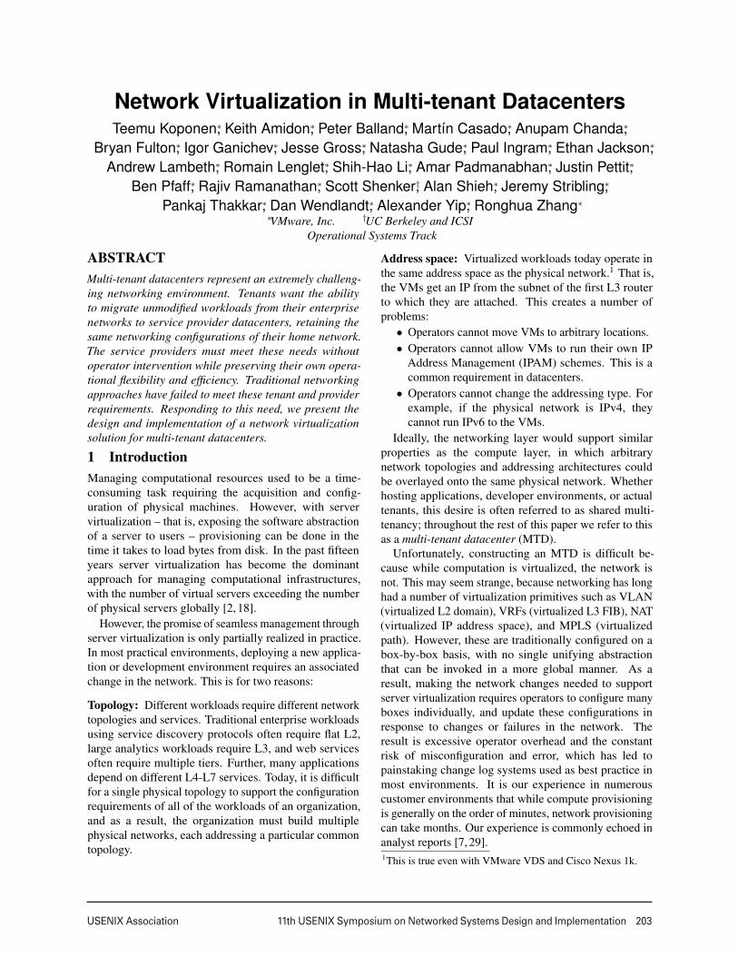
The network hypervisor is a software layer interposedbetween the provider’s physical forwarding infrastructureand the tenant control planes, as depicted in Figure 1.Its purpose is to provide the proper abstractions both totenant’s control planes and endpoints; we describe theseabstractions below:
VM
CP
Network Hypervisor
Physical Forwarding Infrastructure
Control Abstraction
L2 L3 L2 VM
CP CP
Packet Abstraction
Figure 1: A network hypervisor sits on top of the service providerinfrastructure and provides the tenant control planes with a controlabstraction and VMs with a packet abstraction.
Control abstraction. This abstraction must allow ten-ants to define a set of logical network elements (or, as wewill call them, logical datapaths) that they can configure(through their control planes) as they would physicalnetwork elements. While conceptually each tenant hasits own control planes, the network hypervisor providesthe control plane implementations for the defined logicalnetwork elements.2 Each logical datapath is definedby a packet forwarding pipeline interface that, similarto modern forwarding ASICs, contains a sequence oflookup tables, each capable of matching over packetheaders and metadata established by earlier pipelinestages. At each stage, packet headers can be modified orthe packet can be dropped altogether. The pipeline resultsin a forwarding decision, which is saved to the packet’smetadata, and the packet is then sent out the appropriateport. Since our logical datapaths are implemented insoftware virtual switches, we have more flexibility thanASIC implementations; datapaths need not hardcode thetype or number of lookup tables and the lookup tables canmatch over arbitrary packet header fields.Packet abstraction. This abstraction must enable pack-ets sent by endpoints in the MTD to be given the sameswitching, routing and filtering service they would havein the tenant’s home network. This can be accomplishedwithin the packet forwarding pipeline model describedabove. For instance, the control plane might want toprovide basic L2 forwarding semantics in the form ofa logical switch, which connects some set of tenantVMs (each of which has its own MAC address and isrepresented by a logical port on the switch). To achievethis, the control plane could populate a single logicalforwarding table with entries explicitly matching ondestination MAC addresses and sending the matchingpackets to ports connected to the corresponding VMs.Alternatively, the control plane could install a speciallearning flow that forwards packets to ports where trafficfrom the destination MAC address was last received(which will time out in the absence of new traffic)and simply flood unknown packets. Similarly, it couldbroadcast destination addresses with a flow entry thatsends packets to all logical ports (excluding the port onwhich the packet was received) on the logical switch.2In other words, the network hypervisor does not run third-party control plane binaries but the functionality is part of thehypervisor itself. While running a third-party control plane stackwould be feasible, we have had no use case for it yet.
2
USENIX Association 11th USENIX Symposium on Networked Systems Design and Implementation 205
Logical Datapath 2
Logical Datapath 1
SourcevNIC
Logical Forwarding
Dest.vNIC
Source Hypervisor DstTunneling
Logical Ingress
Port
Logical Egress
Port
Physical Datapath (OVS) Physical
Fabric(ECMP)
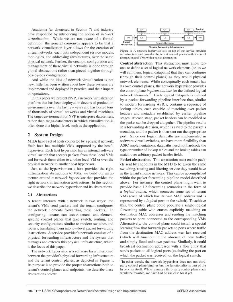
Figure 2: The virtual switch of the originating host hypervisorimplements logical forwarding. After the packet has traversed thelogical datapaths and their tables, the host tunnels it across the physicalnetwork to the receiving host hypervisor for delivery to the destinationVM.
2.2 Virtualization Architecture
The network hypervisor supports these abstractions byimplementing tenant-specific logical datapaths on top ofthe provider’s physical forwarding infrastructure, andthese logical datapaths provide the appropriate controland packet abstractions to each tenant.
In our NVP design, we implement the logical datapathsin the software virtual switches on each host, leveraging aset of tunnels between every pair of host-hypervisors (sothe physical network sees nothing other than what appearsto be ordinary IP traffic between the physical hosts). Thelogical datapath is almost entirely implemented on thevirtual switch where the originating VM resides; afterthe logical datapath reaches a forwarding decision, thevirtual switch tunnels it over the physical network tothe receiving host hypervisor, which decapsulates thepacket and sends it to the destination VM (see Figure 2).A centralized SDN controller cluster is responsible forconfiguring virtual switches with the appropriate logicalforwarding rules as tenants show up in the network.3
While tunnels can efficiently implement logical point-to-point communication, additional support is neededfor logical broadcast or multicast services. For packetreplication, NVP constructs a simple multicast overlayusing additional physical forwarding elements (x86-basedhosts running virtual switching software) called servicenodes. Once a logical forwarding decision results in theneed for packet replication, the host tunnels the packetto a service node, which then replicates the packet toall host hypervisors that need to deliver a copy to theirlocal VMs. For deployments not concerned about thebroadcast traffic volume, NVP supports configurationswithout service nodes: the sending host-hypervisor sendsa copy of the packet directly to each host hypervisorneeding one.
In addition, some tenants want to interconnect theirlogical network with their existing physical one. This
3NVP does not control physical switches, and thus does notcontrol how traffic between hypervisors is routed. Instead, it isassumed the physical network provides uniform capacity acrossthe servers, building on ECMP-based load-balancing.
Hypervisor Hypervisor
Gateway Cluster
VM1 VM2 VM3 VM4
Physical,Non-
virtualizedWorkloads
Service Node Cluster
Hypervisor
VM5 VM6
Controller Cluster
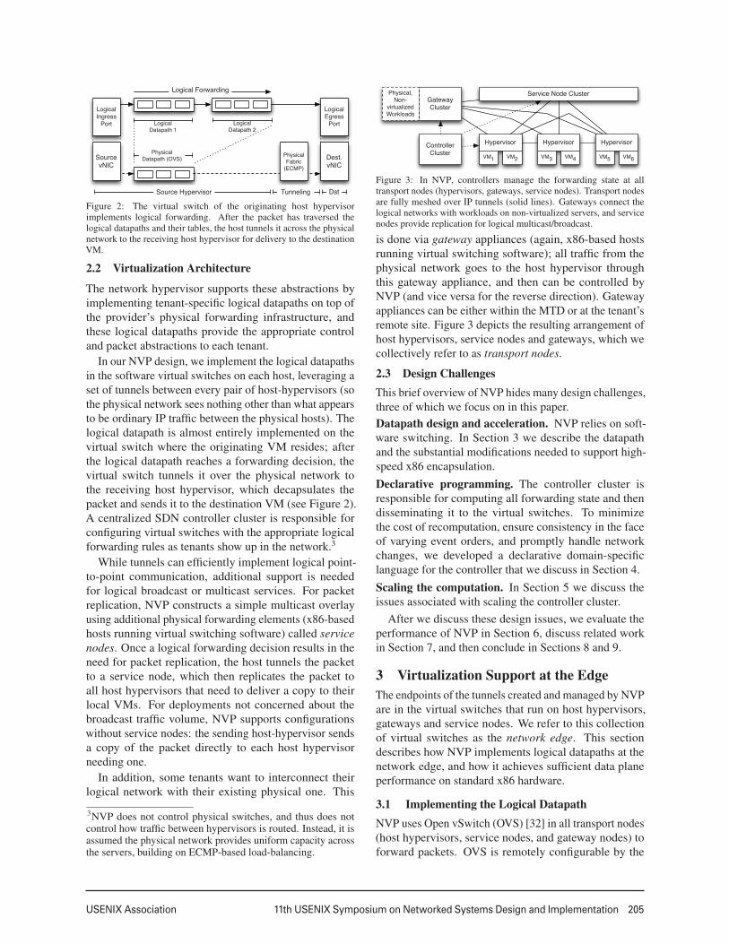
Figure 3: In NVP, controllers manage the forwarding state at alltransport nodes (hypervisors, gateways, service nodes). Transport nodesare fully meshed over IP tunnels (solid lines). Gateways connect thelogical networks with workloads on non-virtualized servers, and servicenodes provide replication for logical multicast/broadcast.
is done via gateway appliances (again, x86-based hostsrunning virtual switching software); all traffic from thephysical network goes to the host hypervisor throughthis gateway appliance, and then can be controlled byNVP (and vice versa for the reverse direction). Gatewayappliances can be either within the MTD or at the tenant’sremote site. Figure 3 depicts the resulting arrangement ofhost hypervisors, service nodes and gateways, which wecollectively refer to as transport nodes.
2.3 Design ChallengesThis brief overview of NVP hides many design challenges,three of which we focus on in this paper.Datapath design and acceleration. NVP relies on soft-ware switching. In Section 3 we describe the datapathand the substantial modifications needed to support high-speed x86 encapsulation.Declarative programming. The controller cluster isresponsible for computing all forwarding state and thendisseminating it to the virtual switches. To minimizethe cost of recomputation, ensure consistency in the faceof varying event orders, and promptly handle networkchanges, we developed a declarative domain-specificlanguage for the controller that we discuss in Section 4.Scaling the computation. In Section 5 we discuss theissues associated with scaling the controller cluster.
After we discuss these design issues, we evaluate theperformance of NVP in Section 6, discuss related workin Section 7, and then conclude in Sections 8 and 9.
3 Virtualization Support at the EdgeThe endpoints of the tunnels created and managed by NVPare in the virtual switches that run on host hypervisors,gateways and service nodes. We refer to this collectionof virtual switches as the network edge. This sectiondescribes how NVP implements logical datapaths at thenetwork edge, and how it achieves sufficient data planeperformance on standard x86 hardware.
3.1 Implementing the Logical DatapathNVP uses Open vSwitch (OVS) [32] in all transport nodes(host hypervisors, service nodes, and gateway nodes) toforward packets. OVS is remotely configurable by the
3
206 11th USENIX Symposium on Networked Systems Design and Implementation USENIX Association
NVP controller cluster via two protocols: one that caninspect and modify a set of flow tables (analogous toflow tables in physical switches),4 and one that allows thecontroller to create and manage overlay tunnels and todiscover which VMs are hosted at a hypervisor [31].
The controller cluster uses these protocols to implementpacket forwarding for logical datapaths. Each logicaldatapath consists of a series (pipeline) of logical flowtables, each with its own globally-unique identifier.The tables consist of a set of flow entries that specifyexpressions to match against the header of a packet, andactions to take on the packet when a given expression issatisfied. Possible actions include modifying a packet,dropping it, sending it to a given egress port on the logicaldatapath, and modifying in-memory metadata (analogousto registers on physical switches) associated with thepacket and resubmitting it back to the datapath for furtherprocessing. A flow expression can match against thismetadata, in addition to the packet’s header. NVP writesthe flow entries for each logical datapath to a single OVSflow table at each virtual switch that participates in thelogical datapath. We emphasize that this model of alogical table pipeline (as opposed to a single table) is thekey to allowing tenants to use existing forwarding policieswith little or no change: with a table pipeline availableto the control plane, tenants can be exposed to featuresand configuration models similar to ASIC-based switchesand routers, and therefore the tenants can continue to usea familiar pipeline-based mental model.
Any packet entering OVS – either from a virtualnetwork interface card (vNIC) attached to a VM, anoverlay tunnel from a different transport node, or aphysical network interface card (NIC) – must be sentthrough the logical pipeline corresponding to the logicaldatapath to which the packet belongs. For vNIC and NICtraffic, the service provider tells the controller clusterwhich ports on the transport node (vNICs or NICs)correspond to which logical datapath (see Section 5);for overlay traffic, the tunnel header of the incomingpacket contains this information. Then, the virtualswitch connects each packet to its logical pipeline bypre-computed flows that NVP writes into the OVS flowtable, which match a packet based on its ingress portand add to the packet’s metadata an identifier for the firstlogical flow table of the packet’s logical datapath. Asits action, this flow entry resubmits the packet back tothe OVS flow table to begin its traversal of the logicalpipeline.
The control plane abstraction NVP provides internallyfor programming the tables of the logical pipelines islargely the same as the interface to OVS’s flow table and
4We use OpenFlow [27] for this protocol, though any flowmanagement protocol with sufficient flexibility would work.
NVP writes logical flow entries directly to OVS, with twoimportant differences:
• Matches. Before each logical flow entry is written toOVS, NVP augments it to include a match over thepacket’s metadata for the logical table’s identifier.This enforces isolation from other logical datapathsand places the lookup entry at the proper stage ofthe logical pipeline. In addition to this forced match,the control plane can program entries that matchover arbitrary logical packet headers, and can usepriorities to implement longest-prefix matching aswell as complex ACL rules.
• Actions. NVP modifies each logical action sequenceof a flow entry to write the identifier of the nextlogical flow table to the packet’s metadata and toresubmit the packet back to the OVS flow table.This creates the logical pipeline, and also preventsthe logical control plane from creating a flow entrythat forwards a packet to a different logical datapath.
At the end of the packet’s traversal of the logicalpipeline it is expected that a forwarding decision for thatpacket has been made: either drop the packet, or forward itto one or more logical egress ports. In the latter case, NVPuses a special action to save this forwarding decision inthe packet’s metadata. (Dropping translates to simply notresubmitting a packet to the next logical table.) After thelogical pipeline, the packet is then matched against egressflow entries written by the controller cluster according totheir logical destination. For packets destined for logicalendpoints hosted on other hypervisors (or for physicalnetworks not controlled by NVP), the action encapsulatesthe packet with a tunnel header that includes the logicalforwarding decision, and outputs the packet to a tunnelport. This tunnel port leads to another hypervisor forunicast traffic to another VM, a service node in the caseof broadcast and multicast traffic, or a gateway node forphysical network destinations. If the endpoint happens tobe hosted on the same hypervisor, it can be output directlyto the logical endpoint’s vNIC port on the virtual switch.5
At a receiving hypervisor, NVP has placed flow entriesthat match over both the physical ingress port for that endof the tunnel and the logical forwarding decision presentin the tunnel header. The flow entry then outputs thepacket to the corresponding local vNIC. A similar patternapplies to traffic received by service and gateway nodes.
The above discussion centers on a single L2 datapath,but generalizes to full logical topologies consistingof several L2 datapaths interconnected by L3 router5For brevity, we don’t discuss logical MAC learning or statefulmatching operations, but in short, the logical control plane canprovide actions that create new lookup entries in the logicaltables, based on incoming packets. These primitives allow thecontrol plane to implement L2 learning and stateful ACLs, in amanner similar to advanced physical forwarding ASICs.
4
USENIX Association 11th USENIX Symposium on Networked Systems Design and Implementation 207
ACL L2 ACL
Map
VM
Map
ACL L2 L3 ACL
Map
ACLACL L2
Map Tunnel
LogicalPhysical
Logical Datapath 1 Logical Datapath 2 Logical Datapath 3
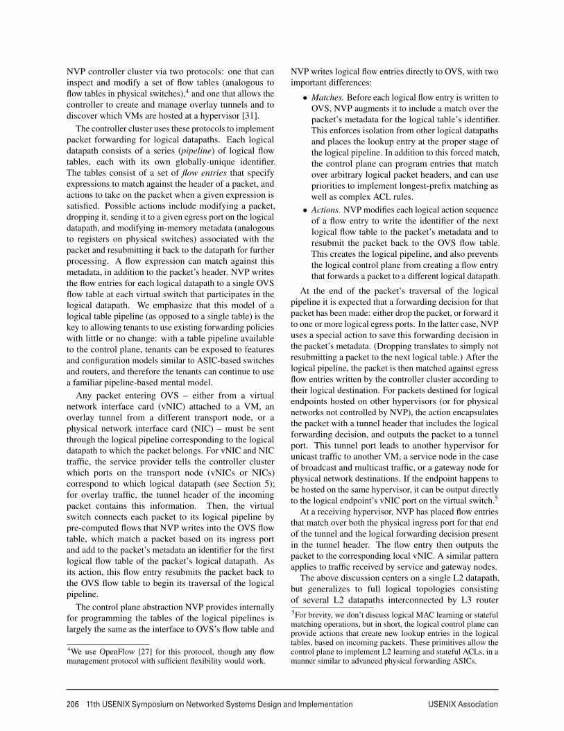
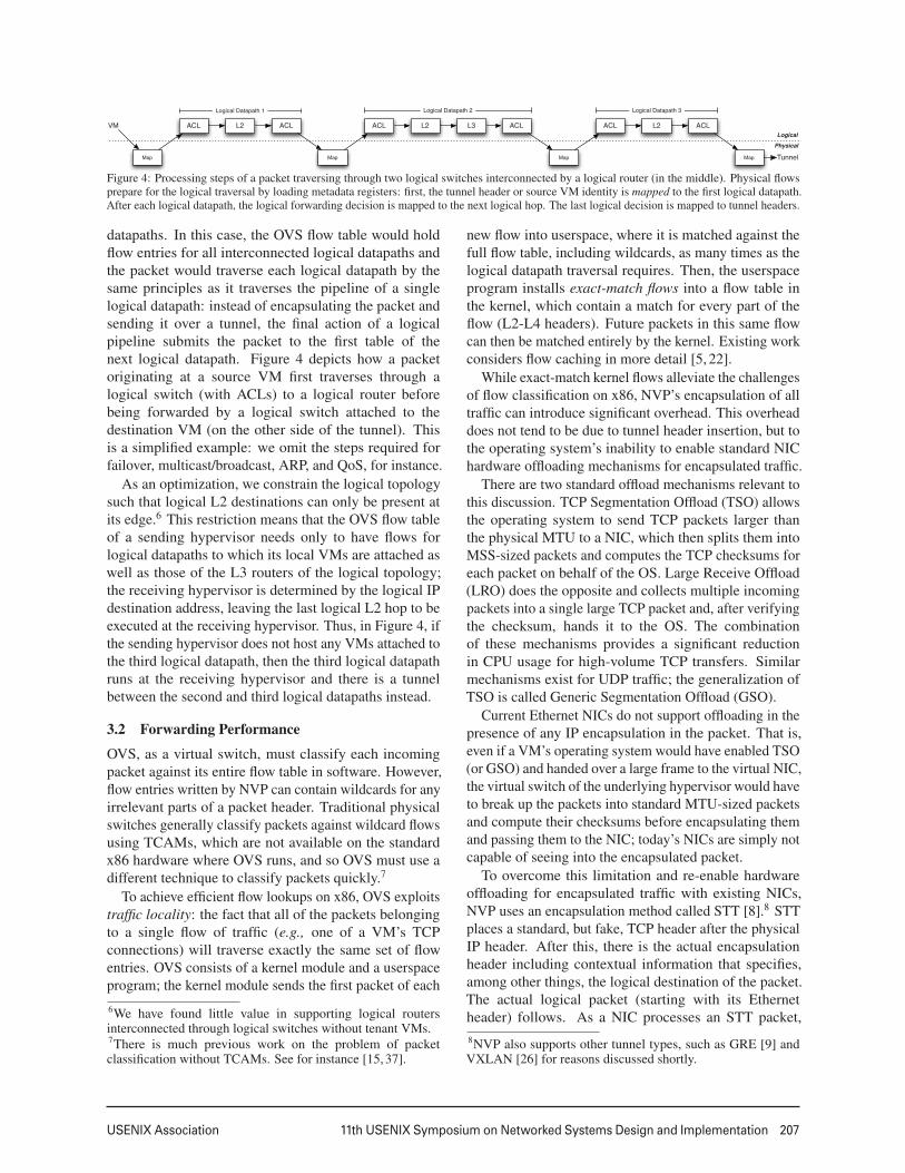
Figure 4: Processing steps of a packet traversing through two logical switches interconnected by a logical router (in the middle). Physical flowsprepare for the logical traversal by loading metadata registers: first, the tunnel header or source VM identity is mapped to the first logical datapath.After each logical datapath, the logical forwarding decision is mapped to the next logical hop. The last logical decision is mapped to tunnel headers.
datapaths. In this case, the OVS flow table would holdflow entries for all interconnected logical datapaths andthe packet would traverse each logical datapath by thesame principles as it traverses the pipeline of a singlelogical datapath: instead of encapsulating the packet andsending it over a tunnel, the final action of a logicalpipeline submits the packet to the first table of thenext logical datapath. Figure 4 depicts how a packetoriginating at a source VM first traverses through alogical switch (with ACLs) to a logical router beforebeing forwarded by a logical switch attached to thedestination VM (on the other side of the tunnel). Thisis a simplified example: we omit the steps required forfailover, multicast/broadcast, ARP, and QoS, for instance.
As an optimization, we constrain the logical topologysuch that logical L2 destinations can only be present atits edge.6 This restriction means that the OVS flow tableof a sending hypervisor needs only to have flows forlogical datapaths to which its local VMs are attached aswell as those of the L3 routers of the logical topology;the receiving hypervisor is determined by the logical IPdestination address, leaving the last logical L2 hop to beexecuted at the receiving hypervisor. Thus, in Figure 4, ifthe sending hypervisor does not host any VMs attached tothe third logical datapath, then the third logical datapathruns at the receiving hypervisor and there is a tunnelbetween the second and third logical datapaths instead.
3.2 Forwarding Performance
OVS, as a virtual switch, must classify each incomingpacket against its entire flow table in software. However,flow entries written by NVP can contain wildcards for anyirrelevant parts of a packet header. Traditional physicalswitches generally classify packets against wildcard flowsusing TCAMs, which are not available on the standardx86 hardware where OVS runs, and so OVS must use adifferent technique to classify packets quickly.7
To achieve efficient flow lookups on x86, OVS exploitstraffic locality: the fact that all of the packets belongingto a single flow of traffic (e.g., one of a VM’s TCPconnections) will traverse exactly the same set of flowentries. OVS consists of a kernel module and a userspaceprogram; the kernel module sends the first packet of each6We have found little value in supporting logical routersinterconnected through logical switches without tenant VMs.7There is much previous work on the problem of packetclassification without TCAMs. See for instance [15, 37].
new flow into userspace, where it is matched against thefull flow table, including wildcards, as many times as thelogical datapath traversal requires. Then, the userspaceprogram installs exact-match flows into a flow table inthe kernel, which contain a match for every part of theflow (L2-L4 headers). Future packets in this same flowcan then be matched entirely by the kernel. Existing workconsiders flow caching in more detail [5, 22].
While exact-match kernel flows alleviate the challengesof flow classification on x86, NVP’s encapsulation of alltraffic can introduce significant overhead. This overheaddoes not tend to be due to tunnel header insertion, but tothe operating system’s inability to enable standard NIChardware offloading mechanisms for encapsulated traffic.
There are two standard offload mechanisms relevant tothis discussion. TCP Segmentation Offload (TSO) allowsthe operating system to send TCP packets larger thanthe physical MTU to a NIC, which then splits them intoMSS-sized packets and computes the TCP checksums foreach packet on behalf of the OS. Large Receive Offload(LRO) does the opposite and collects multiple incomingpackets into a single large TCP packet and, after verifyingthe checksum, hands it to the OS. The combinationof these mechanisms provides a significant reductionin CPU usage for high-volume TCP transfers. Similarmechanisms exist for UDP traffic; the generalization ofTSO is called Generic Segmentation Offload (GSO).
Current Ethernet NICs do not support offloading in thepresence of any IP encapsulation in the packet. That is,even if a VM’s operating system would have enabled TSO(or GSO) and handed over a large frame to the virtual NIC,the virtual switch of the underlying hypervisor would haveto break up the packets into standard MTU-sized packetsand compute their checksums before encapsulating themand passing them to the NIC; today’s NICs are simply notcapable of seeing into the encapsulated packet.
To overcome this limitation and re-enable hardwareoffloading for encapsulated traffic with existing NICs,NVP uses an encapsulation method called STT [8].8 STTplaces a standard, but fake, TCP header after the physicalIP header. After this, there is the actual encapsulationheader including contextual information that specifies,among other things, the logical destination of the packet.The actual logical packet (starting with its Ethernetheader) follows. As a NIC processes an STT packet,8NVP also supports other tunnel types, such as GRE [9] andVXLAN [26] for reasons discussed shortly.
5
208 11th USENIX Symposium on Networked Systems Design and Implementation USENIX Association
it will first encounter this fake TCP header, and considereverything after that to be part of the TCP payload; thus,the NIC can employ its standard offloading mechanisms.
Although on the wire the STT packet looks likestandard TCP packet, the STT protocol is stateless andrequires no TCP handshake procedure between the tunnelendpoints. VMs can run TCP over the logical packetsexchanged over the encapsulation.
Placing contextual information into the encapsulationheader, at the start of the fake TCP payload, allows for asecond optimization: this information is not transferredin every physical packet, but only once for each largepacket sent to the NIC. Therefore, the cost of this contextinformation is amortized over all the segments producedout of the original packet and additional information (e.g.,for debugging) can be included as well.
Using hardware offloading in this way comes with asignificant downside: gaining access to the logical trafficand contextual information requires reassembling thesegments, unlike with traditional encapsulation protocolsin which every datagram seen on wire has all headers inplace. This limitation makes it difficult, if not impossible,for the high-speed forwarding ASICs used in hardwareswitch appliances to inspect encapsulated logical traffic;however, we have found such appliances to be rare inNVP production deployments. Another complication isthat STT may confuse middleboxes on the path. STTuses its own TCP transport port in the fake TCP header,however, and to date administrators have been successfulin punching any necessary holes in middleboxes in thephysical network. For environments where complianceis more important than efficiency, NVP supports other,more standard IP encapsulation protocols.
3.3 Fast Failovers
Providing highly-available dataplane connectivity is apriority for NVP. Logical traffic between VMs flowingover a direct hypervisor-to-hypervisor tunnel clearlycannot survive the failure of either hypervisor, and mustrely on path redundancy provided by the physical networkto survive the failure of any physical network elements.However, the failure of any of the new appliances thatNVP introduces – service and gateway nodes – must causeonly minimal, if any, dataplane outage.
For this reason, NVP deployments have multipleservice nodes, to ensure that any one service nodefailure does not disrupt logical broadcast and multicasttraffic. The controller cluster instructs hypervisors to load-balance their packet replication traffic across a bundle ofservice node tunnels by using flow hashing algorithmssimilar to ECMP [16]. The hypervisor monitors thesetunnels using BFD [21]. If the hypervisor fails to receiveheartbeats from a service node for a configurable period oftime, it removes (without involving the controller cluster)
Hypervisor Hypervisor GatewayVM1 VM2 VM3 VM4 VLAN VLAN
ControllerProvisionedConfiguration (2)
Location information (1) and Forwarding State (3)
Network Hypervisor
Logical Control Planesnlog Logical Datapaths
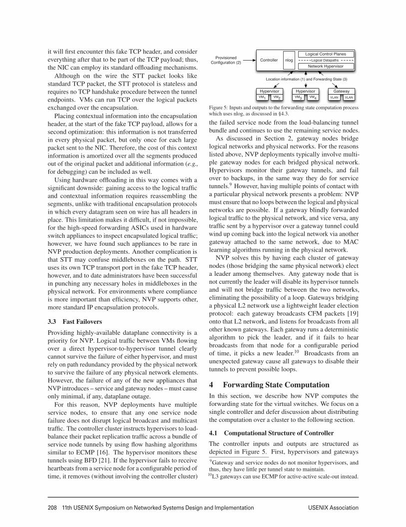
Figure 5: Inputs and outputs to the forwarding state computation processwhich uses nlog, as discussed in §4.3.
the failed service node from the load-balancing tunnelbundle and continues to use the remaining service nodes.
As discussed in Section 2, gateway nodes bridgelogical networks and physical networks. For the reasonslisted above, NVP deployments typically involve multi-ple gateway nodes for each bridged physical network.Hypervisors monitor their gateway tunnels, and failover to backups, in the same way they do for servicetunnels.9 However, having multiple points of contact witha particular physical network presents a problem: NVPmust ensure that no loops between the logical and physicalnetworks are possible. If a gateway blindly forwardedlogical traffic to the physical network, and vice versa, anytraffic sent by a hypervisor over a gateway tunnel couldwind up coming back into the logical network via anothergateway attached to the same network, due to MAClearning algorithms running in the physical network.
NVP solves this by having each cluster of gatewaynodes (those bridging the same physical network) electa leader among themselves. Any gateway node that isnot currently the leader will disable its hypervisor tunnelsand will not bridge traffic between the two networks,eliminating the possibility of a loop. Gateways bridginga physical L2 network use a lightweight leader electionprotocol: each gateway broadcasts CFM packets [19]onto that L2 network, and listens for broadcasts from allother known gateways. Each gateway runs a deterministicalgorithm to pick the leader, and if it fails to hearbroadcasts from that node for a configurable periodof time, it picks a new leader.10 Broadcasts from anunexpected gateway cause all gateways to disable theirtunnels to prevent possible loops.
4 Forwarding State ComputationIn this section, we describe how NVP computes theforwarding state for the virtual switches. We focus on asingle controller and defer discussion about distributingthe computation over a cluster to the following section.
4.1 Computational Structure of ControllerThe controller inputs and outputs are structured asdepicted in Figure 5. First, hypervisors and gateways9Gateway and service nodes do not monitor hypervisors, andthus, they have little per tunnel state to maintain.
10L3 gateways can use ECMP for active-active scale-out instead.
6
USENIX Association 11th USENIX Symposium on Networked Systems Design and Implementation 209
provide the controller with location information for vNICsover the OVS configuration protocol [31] (1), updatingthis information as virtual machines migrate. Hypervisorsalso provide the MAC address for each vNIC.11 Second,service providers configure the system through the NVPAPI (see the following section) (2). This configurationstate changes as new tenants enter the system, as logicalnetwork configuration for these tenants change, and whenthe physical configuration of the overall system (e.g., theset of managed transport nodes) changes.
Based on these inputs, the logical control plane com-putes the logical lookup tables, which the networkhypervisor augments and transforms into physical for-warding state (realized as logical datapaths with givenlogical lookup entries, as discussed in the previoussection). The forwarding state is then pushed to transportnodes via OpenFlow and the OVS configuration protocol(3). OpenFlow flow entries model the full logicalpacket forwarding pipeline, whereas OVS configurationdatabase entries are responsible for the tunnels connectinghypervisors, gateways and service nodes, as well as anylocal queues and scheduling policies.12
The above implies the computational model is en-tirely proactive: the controllers push all the necessaryforwarding state down and do not process any packets.The rationale behind this design is twofold. First, itsimplifies the scaling of the controller cluster becauseinfrequently pushing updates to forwarding instructionsto the switch, instead of continuously punting packets tocontrollers, is a more effective use of resources. Second,and more importantly, failure isolation is critical in thatthe managed transport nodes and their data planes mustremain operational even if connectivity to the controllercluster is transiently lost.
4.2 Computational Challenge
The input and output domains of the controller logicare complex: in total, the controller uses 123 typesof input to generate 81 types of output. A singleinput type corresponds to a single configured logicalfeature or physical property; for instance, a particulartype of logical ACL may be a single logical input type,whereas the location of a vNIC may be a single physicalinput information type. Similarly, each output typecorresponds to a single type of attribute being configuredover OpenFlow or the OVS configuration protocol; forexample, a tunnel parameter and particular type of ACLflow entries are both examples of individual output types.
The total amount of input state is also large, being11The service provider’s cloud management system can provisionthis information directly, if available.
12One can argue for a single flow protocol to program the entireswitch but in our experience trying to fold everything into asingle flow protocol only complicates the design.
proportional to the size of the MTD, and the statechanges frequently as VMs migrate and tenants join,leave, and reconfigure their logical networks. Thecontroller needs to react quickly to the input changes.Given the large total input size and frequent, localizedinput changes, a naïve implementation that reruns thefull input-to-output translation on every change wouldbe computationally inefficient. Incremental computationallows us to recompute only the affected state and pushthe delta down to the network edge. We first useda hand-written state machine to compute and updatethe forwarding state incrementally in response to inputchange events; however, we found this approach to beimpractical due to the number of event types that needto be handled as well as their arbitrary interleavings.Event handling logic must account for dependencieson previous or subsequent events, deferring work orrewriting previously generated outputs as needed. Inmany languages, such code degenerates to a reactive,asynchronous style that is difficult to write, comprehend,and especially test.
4.3 Incremental State Computation with nlog
To overcome this problem, we implemented a domain-specific, declarative language called nlog for computingthe network forwarding state. It allows us to separate logicspecification from the state machine that implements thelogic. The logic is written in a declarative manner thatspecifies a function mapping the controller input to output,without worrying about state transitions and input eventordering. The state transitions are handled by a compilerthat generates the event processing code and by a runtimethat is responsible for consuming the input change eventsand recomputing all affected outputs. Note that nlog isnot used by NVP’s users, only internally by its developers;users interact with NVP via the API (see §5.3).
nlog declarations are Datalog queries: a single dec-laration is a join over a number of tables that producesimmutable tuples for a head table. Any change in thejoined tables results in (incremental) re-evaluation ofthe join and possibly in adding tuples to, or removingtuples from, this head table. Joined tables may beeither input tables representing external changes (inputtypes) or internal tables holding only results computed bydeclarations. Head tables may be internal tables or outputtables (output types), which cause changes external to thenlog runtime engine when tuples are added to or removedfrom the table. nlog does not currently support recursivedeclarations or negation.13 In total, NVP has about 1200declarations and 900 tables (of all three types).
13The lack of negation has had little impact on developmentbut the inability to recurse complicates computations where thenumber of iterations is unknown at compile time. For example,traversing a graph can only be done up to maximum diameter.
7
210 11th USENIX Symposium on Networked Systems Design and Implementation USENIX Association
# 1. Determine tunnel from a source hypervisor# to a remote, destination logical port.tunnel(dst_lport_id, src_hv_id, encap, dst_ip) :-
# Pick logical ports & chosen encap of a datapath.log_port(src_lport_id, log_datapath_id),log_port(dst_lport_id, log_datapath_id),log_datapath_encap(log_datapath_id, encap),
# Determine current port locations (hypervisors).log_port_presence(src_lport_id, src_hv_id),log_port_presence(dst_lport_id, dst_hv_id),
# Map dst hypervisor to IP and omit local tunnels.hypervisor_locator(dst_hv_id, dst_ip),not_equal(src_hv_id, dst_hv_id);
# 2. Establish tunnel via OVS db. Assigned port # will# be in input table ovsdb_tport. Ignore first column.ovsdb_tunnel(src_hv_id, encap, dst_ip) :-
tunnel(_, src_hv_id, encap, dst_ip);
# 3. Construct the flow entry feeding traffic to tunnel.# Before resubmitting packet to this stage, reg1 is# loaded with ’stage id’ corresponding to log port.ovs_flow(src_hv_id, of_expr, of_actions) :-
tunnel(dst_lport_id, src_hv_id, encap, dst_ip),lport_stage_id(dst_lport_id, processing_stage_id),flow_expr_match_reg1(processing_stage_id, of_expr),# OF output action needs the assigned tunnel port #.ovsdb_tport(src_hv_id, encap, dst_ip, port_no),flow_output_action(port_no, of_actions);
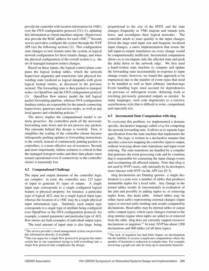
Figure 6: Steps to establish a tunnel: 1) determining the tunnels, 2) creating OVS db entries, and 3) creating OF flows to output packets into tunnels.
The code snippet in Figure 6 has simplified nlogdeclarations for creating OVS configuration databasetunnel entries as well as OpenFlow flow entries feedingpackets to tunnels. The tunnels depend on API-providedinformation, such as the logical datapath configurationand the tunnel encapsulation type, as well as the locationof vNICs. The computed flow entries are a part of theoverall packet processing pipeline, and thus, they usea controller-assigned stage identifier to match with thepackets sent to this stage by the previous processing stage.
The above declaration updates the head table tunnel forall pairs of logical ports in the logical datapath identifiedby log_datapath_id. The head table is an internal tableconsisting of rows each with four data columns; a singlerow corresponds to a tunnel to a logical port dst_lport_idon a remote hypervisor dst_hv_id (reachable at dst_ip)on a hypervisor identified by src_hv_id for a specificencapsulation type (encap) configured for the logicaldatapath. We use a function not_equal to exclude tunnelsbetween logical ports on a single hypervisor. We willreturn to functions shortly.
In the next two declarations, the internal tunnel tableis used to derive both the OVS database entries andOpenFlow flows to output tables ovsdb_tunnel andovs_flow. The declaration computing the flows uses func-tions flow_expr_reg1 and flow_output_action to computethe corresponding OpenFlow expression (matching overregister 1) and actions (sending to a port assigned forthe tunnel). As VMs migrate, the log_port_presenceinput table is updated to reflect the new locations ofeach log_port_id, which in turn causes correspondingchanges to tunnel. This will result in re-evaluation of thesecond and third declaration, which will result in OVSconfiguration database changes that create or removetunnels on the corresponding hypervisors, as well asOpenFlow entries being inserted or removed. Similarly,as tunnel or logical datapath configuration changes, thedeclarations will be incrementally re-evaluated.
Even though the incremental update model allowsquick convergence after changes, it is not intended forreacting to dataplane failures at dataplane time scales. Forthis reason, NVP precomputes any state necessary fordataplane failure recovery. For instance, the forwarding
state computed for tunnels includes any necessary backuppaths to allow the virtual switch running on a transportnode to react independently to network failures (see §3.3).
Language extensions. Datalog joins can only rearrangeexisting column data. Because most non-trivial programsmust also transform column data, nlog provides extensionmechanisms for specifying transformations in C++.
First, a developer can implement a function table,which is a virtual table where certain columns of a roware a stateless function of others. For example, a functiontable could compute the sum of two integer columns andplace it in a third column, or create OpenFlow matchexpressions or actions (like in the example above). Thebase language provides various functions for primitivecolumn types (e.g., integers, UUIDs). NVP extends thesewith functions operating over flow and action types, whichare used to construct the complex match expressions andaction sequences that constitute the logical datapath flowentries. Finally, the developer is provided with not_equalto express inequality between two columns.
Second, if developers require more complicated trans-formations, they can hook an output and an input tabletogether through arbitrary C++ code. Declarationsproduce tuples into the output table, which transformsthem into C++ and feeds them to the output tableC++ implementation. After processing, the C++ codetransforms them back into tuples and passes them tonlog through the input table. For instance, we use thistechnique to implement hysteresis that dampens externalevents such as a network port status flapping.
5 Controller ClusterIn this section we discuss the design of the controllercluster: the distribution of physical forwarding statecomputation to implement the logical datapaths, theauxiliary distributed services that the distribution of thecomputation requires, and finally the implementation ofthe API provided for the service provider.
5.1 Scaling and Availability of ComputationScaling. The forwarding state computation is easily par-allelizable and NVP divides computation into a loosely-
8
USENIX Association 11th USENIX Symposium on Networked Systems Design and Implementation 211
LogicalControllers
PhysicalControllers
Universal Flows
Transportnodes
Physical Flows
(OpenFlow) & OVS configAPI
PhysicalState
Location Information
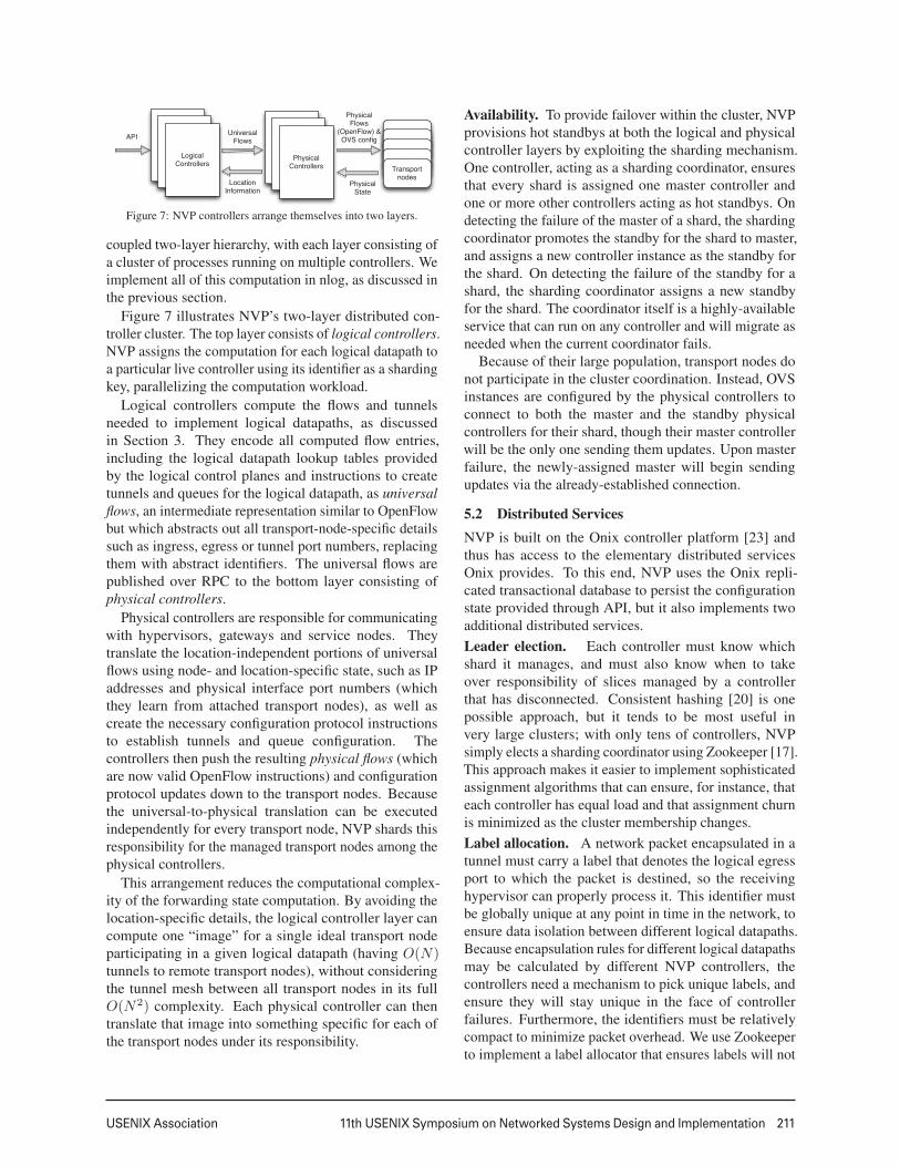
Figure 7: NVP controllers arrange themselves into two layers.
coupled two-layer hierarchy, with each layer consisting ofa cluster of processes running on multiple controllers. Weimplement all of this computation in nlog, as discussed inthe previous section.
Figure 7 illustrates NVP’s two-layer distributed con-troller cluster. The top layer consists of logical controllers.NVP assigns the computation for each logical datapath toa particular live controller using its identifier as a shardingkey, parallelizing the computation workload.
Logical controllers compute the flows and tunnelsneeded to implement logical datapaths, as discussedin Section 3. They encode all computed flow entries,including the logical datapath lookup tables providedby the logical control planes and instructions to createtunnels and queues for the logical datapath, as universalflows, an intermediate representation similar to OpenFlowbut which abstracts out all transport-node-specific detailssuch as ingress, egress or tunnel port numbers, replacingthem with abstract identifiers. The universal flows arepublished over RPC to the bottom layer consisting ofphysical controllers.
Physical controllers are responsible for communicatingwith hypervisors, gateways and service nodes. Theytranslate the location-independent portions of universalflows using node- and location-specific state, such as IPaddresses and physical interface port numbers (whichthey learn from attached transport nodes), as well ascreate the necessary configuration protocol instructionsto establish tunnels and queue configuration. Thecontrollers then push the resulting physical flows (whichare now valid OpenFlow instructions) and configurationprotocol updates down to the transport nodes. Becausethe universal-to-physical translation can be executedindependently for every transport node, NVP shards thisresponsibility for the managed transport nodes among thephysical controllers.
This arrangement reduces the computational complex-ity of the forwarding state computation. By avoiding thelocation-specific details, the logical controller layer cancompute one “image” for a single ideal transport nodeparticipating in a given logical datapath (having O(N)tunnels to remote transport nodes), without consideringthe tunnel mesh between all transport nodes in its fullO(N2) complexity. Each physical controller can thentranslate that image into something specific for each ofthe transport nodes under its responsibility.
Availability. To provide failover within the cluster, NVPprovisions hot standbys at both the logical and physicalcontroller layers by exploiting the sharding mechanism.One controller, acting as a sharding coordinator, ensuresthat every shard is assigned one master controller andone or more other controllers acting as hot standbys. Ondetecting the failure of the master of a shard, the shardingcoordinator promotes the standby for the shard to master,and assigns a new controller instance as the standby forthe shard. On detecting the failure of the standby for ashard, the sharding coordinator assigns a new standbyfor the shard. The coordinator itself is a highly-availableservice that can run on any controller and will migrate asneeded when the current coordinator fails.
Because of their large population, transport nodes donot participate in the cluster coordination. Instead, OVSinstances are configured by the physical controllers toconnect to both the master and the standby physicalcontrollers for their shard, though their master controllerwill be the only one sending them updates. Upon masterfailure, the newly-assigned master will begin sendingupdates via the already-established connection.
5.2 Distributed ServicesNVP is built on the Onix controller platform [23] andthus has access to the elementary distributed servicesOnix provides. To this end, NVP uses the Onix repli-cated transactional database to persist the configurationstate provided through API, but it also implements twoadditional distributed services.Leader election. Each controller must know whichshard it manages, and must also know when to takeover responsibility of slices managed by a controllerthat has disconnected. Consistent hashing [20] is onepossible approach, but it tends to be most useful invery large clusters; with only tens of controllers, NVPsimply elects a sharding coordinator using Zookeeper [17].This approach makes it easier to implement sophisticatedassignment algorithms that can ensure, for instance, thateach controller has equal load and that assignment churnis minimized as the cluster membership changes.Label allocation. A network packet encapsulated in atunnel must carry a label that denotes the logical egressport to which the packet is destined, so the receivinghypervisor can properly process it. This identifier mustbe globally unique at any point in time in the network, toensure data isolation between different logical datapaths.Because encapsulation rules for different logical datapathsmay be calculated by different NVP controllers, thecontrollers need a mechanism to pick unique labels, andensure they will stay unique in the face of controllerfailures. Furthermore, the identifiers must be relativelycompact to minimize packet overhead. We use Zookeeperto implement a label allocator that ensures labels will not
9
212 11th USENIX Symposium on Networked Systems Design and Implementation USENIX Association
be reused until NVP deletes the corresponding datapath.The logical controllers use this label allocation serviceto assign logical egress port labels at the time of logicaldatapath creation, and then disseminate the labels to thephysical controllers via universal flows.
5.3 API for Service ProvidersTo support integrating with a service provider’s existingcloud management system, NVP exposes an HTTP-basedREST API in which network elements, physical or logical,are presented as objects. Examples of physical networkelements include transport nodes, while logical switches,ports, and routers are logical network elements. Logicalcontrollers react to changes to these logical elements,enabling or disabling features on the correspondinglogical control plane accordingly. The cloud managementsystem uses these APIs to provision tenant workloads,and a command-line or a graphical shell implementationcould map these APIs to a human-friendly interface forservice provider administrators and/or their customers.
A single API request can require state from multipletransport nodes, or both logical and physical information.Thus, API operations generally merge information frommultiple controllers. Depending on the operation, NVPmay retrieve information on-demand in response to aspecific API request, or proactively, by continuouslycollecting the necessary state.
6 EvaluationIn this section, we present measurements both for thecontroller cluster and the edge datapath implementation.
6.1 Controller ClusterSetup. The configuration in the following tests has 3,000simulated hypervisors, each with 21 vNICs for a totalof 63,000 logical ports. In total, there are 7000 logicaldatapaths, each coupled with a logical control planemodeling a logical switch. The average size of a logicaldatapath is 9 ports, but the size of each logical datapathvaries from 2 to 64. The test configures the logical controlplanes to use port ACLs on 49,188 of the logical portsand generic ACLs for 1,553 of the logical switches.14
The test control cluster has three nodes. Each controlleris a bare-metal Intel Xeon 2.4GHz server with 12 cores,96GB of memory, and 400GB hard disk. The logical andphysical computation load is distributed evenly among thecontrollers, with one master and one standby per shard.The physical network is a dedicated switched network.
Each simulated hypervisor is a Linux VM that containsan OVS instance with a TUN device simulating eachvirtual interface on the hypervisor. The simulated hyper-visors run within XenServer 5.6 physical hypervisors, and
14This serves as our base validation test; other tests stress thesystem further both in scale and in complexity of configurations.
0
20
40
60
80
100
0 500 1000 1500 2000 2500 3000
Time Since Start (s)
Figure 8: Cold start connectivity as a percentage of all pairs connected.
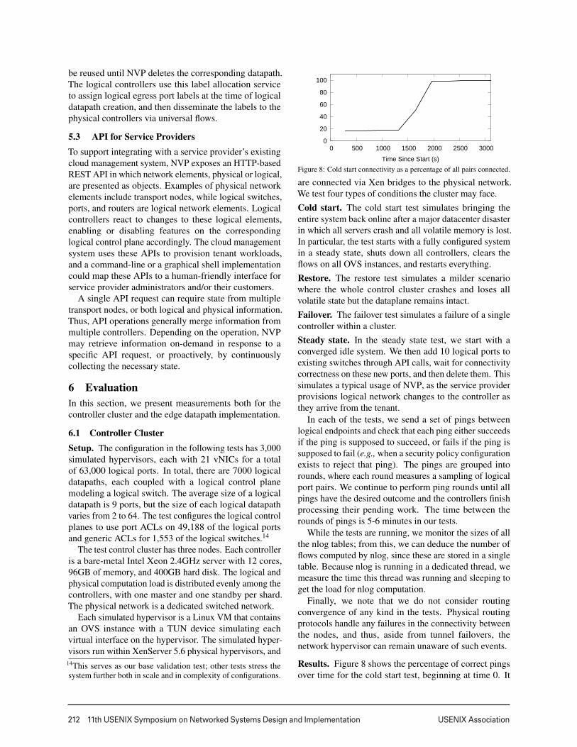
are connected via Xen bridges to the physical network.We test four types of conditions the cluster may face.Cold start. The cold start test simulates bringing theentire system back online after a major datacenter disasterin which all servers crash and all volatile memory is lost.In particular, the test starts with a fully configured systemin a steady state, shuts down all controllers, clears theflows on all OVS instances, and restarts everything.Restore. The restore test simulates a milder scenariowhere the whole control cluster crashes and loses allvolatile state but the dataplane remains intact.Failover. The failover test simulates a failure of a singlecontroller within a cluster.Steady state. In the steady state test, we start with aconverged idle system. We then add 10 logical ports toexisting switches through API calls, wait for connectivitycorrectness on these new ports, and then delete them. Thissimulates a typical usage of NVP, as the service providerprovisions logical network changes to the controller asthey arrive from the tenant.
In each of the tests, we send a set of pings betweenlogical endpoints and check that each ping either succeedsif the ping is supposed to succeed, or fails if the ping issupposed to fail (e.g., when a security policy configurationexists to reject that ping). The pings are grouped intorounds, where each round measures a sampling of logicalport pairs. We continue to perform ping rounds until allpings have the desired outcome and the controllers finishprocessing their pending work. The time between therounds of pings is 5-6 minutes in our tests.
While the tests are running, we monitor the sizes of allthe nlog tables; from this, we can deduce the number offlows computed by nlog, since these are stored in a singletable. Because nlog is running in a dedicated thread, wemeasure the time this thread was running and sleeping toget the load for nlog computation.
Finally, we note that we do not consider routingconvergence of any kind in the tests. Physical routingprotocols handle any failures in the connectivity betweenthe nodes, and thus, aside from tunnel failovers, thenetwork hypervisor can remain unaware of such events.
Results. Figure 8 shows the percentage of correct pingsover time for the cold start test, beginning at time 0. It
10
USENIX Association 11th USENIX Symposium on Networked Systems Design and Implementation 213
400k
800k
1.2M
1.6M
2.0M
0 500 1000 1500 2000 2500 3000
8M
16M
24M
32M
40M
Flo
ws
Tup
les
Time Since Start (s)
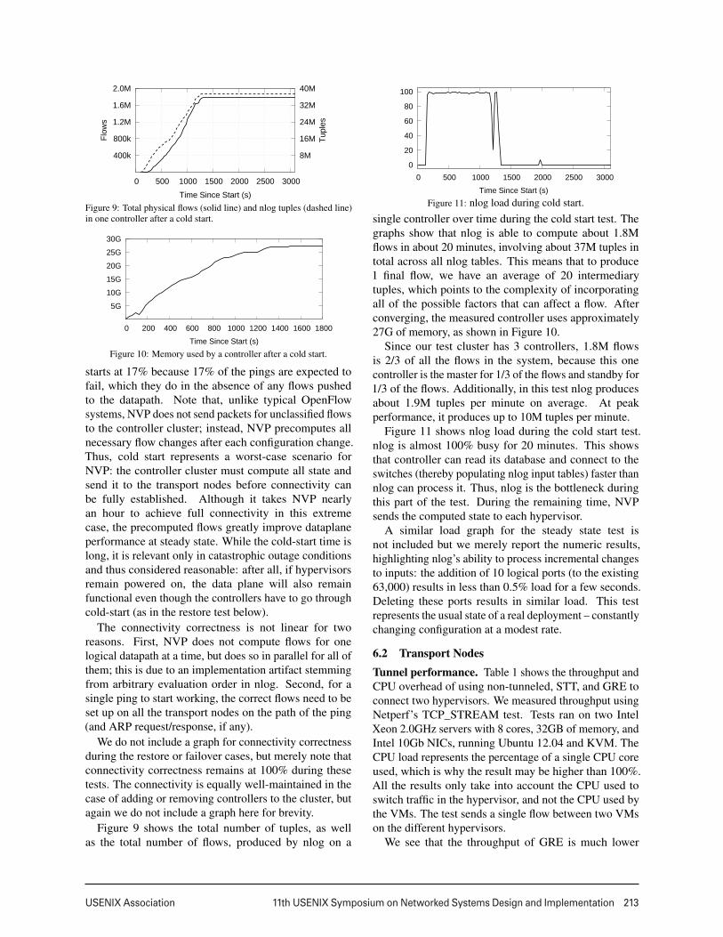
Figure 9: Total physical flows (solid line) and nlog tuples (dashed line)in one controller after a cold start.
5G
10G
15G
20G
25G
30G
0 200 400 600 800 1000 1200 1400 1600 1800
Time Since Start (s)
Figure 10: Memory used by a controller after a cold start.
starts at 17% because 17% of the pings are expected tofail, which they do in the absence of any flows pushedto the datapath. Note that, unlike typical OpenFlowsystems, NVP does not send packets for unclassified flowsto the controller cluster; instead, NVP precomputes allnecessary flow changes after each configuration change.Thus, cold start represents a worst-case scenario forNVP: the controller cluster must compute all state andsend it to the transport nodes before connectivity canbe fully established. Although it takes NVP nearlyan hour to achieve full connectivity in this extremecase, the precomputed flows greatly improve dataplaneperformance at steady state. While the cold-start time islong, it is relevant only in catastrophic outage conditionsand thus considered reasonable: after all, if hypervisorsremain powered on, the data plane will also remainfunctional even though the controllers have to go throughcold-start (as in the restore test below).
The connectivity correctness is not linear for tworeasons. First, NVP does not compute flows for onelogical datapath at a time, but does so in parallel for all ofthem; this is due to an implementation artifact stemmingfrom arbitrary evaluation order in nlog. Second, for asingle ping to start working, the correct flows need to beset up on all the transport nodes on the path of the ping(and ARP request/response, if any).
We do not include a graph for connectivity correctnessduring the restore or failover cases, but merely note thatconnectivity correctness remains at 100% during thesetests. The connectivity is equally well-maintained in thecase of adding or removing controllers to the cluster, butagain we do not include a graph here for brevity.
Figure 9 shows the total number of tuples, as wellas the total number of flows, produced by nlog on a
0
20
40
60
80
100
0 500 1000 1500 2000 2500 3000
Time Since Start (s)
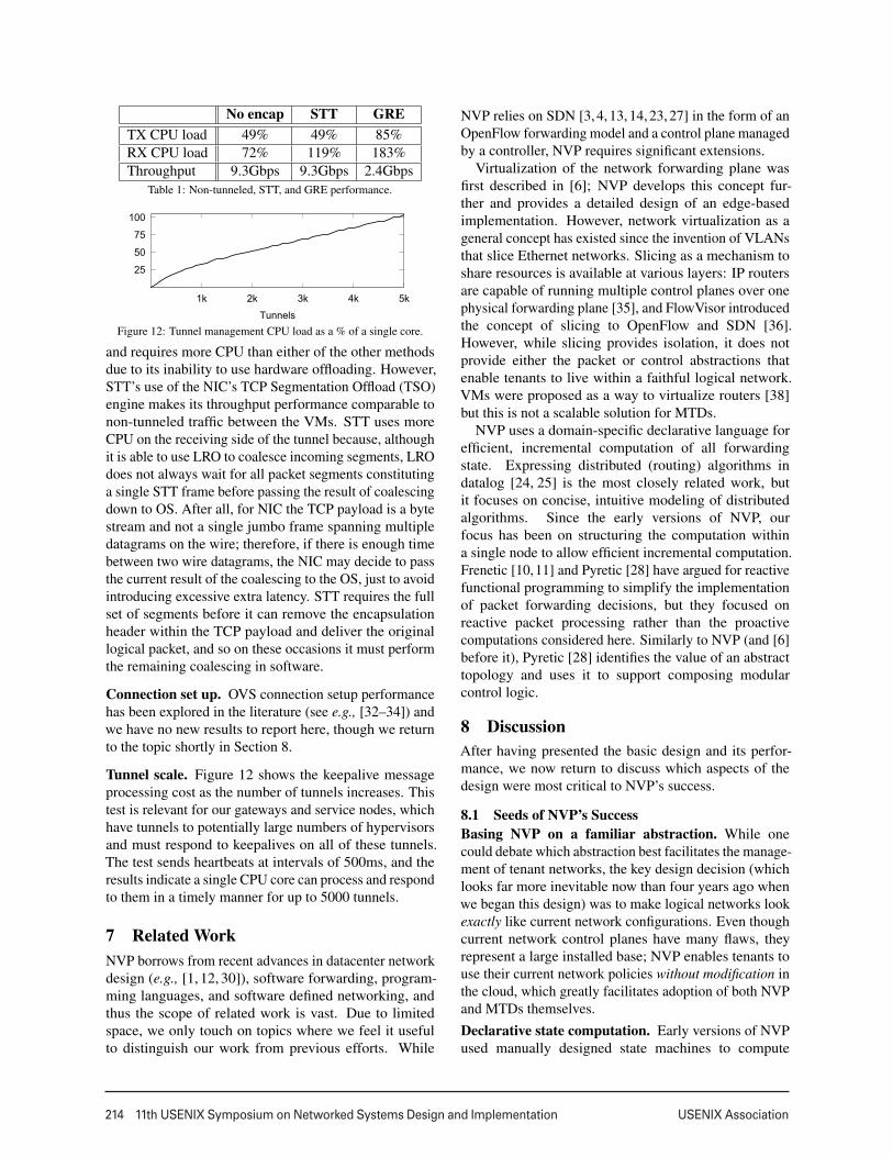
Figure 11: nlog load during cold start.
single controller over time during the cold start test. Thegraphs show that nlog is able to compute about 1.8Mflows in about 20 minutes, involving about 37M tuples intotal across all nlog tables. This means that to produce1 final flow, we have an average of 20 intermediarytuples, which points to the complexity of incorporatingall of the possible factors that can affect a flow. Afterconverging, the measured controller uses approximately27G of memory, as shown in Figure 10.
Since our test cluster has 3 controllers, 1.8M flowsis 2/3 of all the flows in the system, because this onecontroller is the master for 1/3 of the flows and standby for1/3 of the flows. Additionally, in this test nlog producesabout 1.9M tuples per minute on average. At peakperformance, it produces up to 10M tuples per minute.
Figure 11 shows nlog load during the cold start test.nlog is almost 100% busy for 20 minutes. This showsthat controller can read its database and connect to theswitches (thereby populating nlog input tables) faster thannlog can process it. Thus, nlog is the bottleneck duringthis part of the test. During the remaining time, NVPsends the computed state to each hypervisor.
A similar load graph for the steady state test isnot included but we merely report the numeric results,highlighting nlog’s ability to process incremental changesto inputs: the addition of 10 logical ports (to the existing63,000) results in less than 0.5% load for a few seconds.Deleting these ports results in similar load. This testrepresents the usual state of a real deployment – constantlychanging configuration at a modest rate.
6.2 Transport NodesTunnel performance. Table 1 shows the throughput andCPU overhead of using non-tunneled, STT, and GRE toconnect two hypervisors. We measured throughput usingNetperf’s TCP_STREAM test. Tests ran on two IntelXeon 2.0GHz servers with 8 cores, 32GB of memory, andIntel 10Gb NICs, running Ubuntu 12.04 and KVM. TheCPU load represents the percentage of a single CPU coreused, which is why the result may be higher than 100%.All the results only take into account the CPU used toswitch traffic in the hypervisor, and not the CPU used bythe VMs. The test sends a single flow between two VMson the different hypervisors.
We see that the throughput of GRE is much lower
11
214 11th USENIX Symposium on Networked Systems Design and Implementation USENIX Association
No encap STT GRETX CPU load 49% 49% 85%RX CPU load 72% 119% 183%Throughput 9.3Gbps 9.3Gbps 2.4Gbps
Table 1: Non-tunneled, STT, and GRE performance.
25
50
75
100
1k 2k 3k 4k 5k
TunnelsFigure 12: Tunnel management CPU load as a % of a single core.
and requires more CPU than either of the other methodsdue to its inability to use hardware offloading. However,STT’s use of the NIC’s TCP Segmentation Offload (TSO)engine makes its throughput performance comparable tonon-tunneled traffic between the VMs. STT uses moreCPU on the receiving side of the tunnel because, althoughit is able to use LRO to coalesce incoming segments, LROdoes not always wait for all packet segments constitutinga single STT frame before passing the result of coalescingdown to OS. After all, for NIC the TCP payload is a bytestream and not a single jumbo frame spanning multipledatagrams on the wire; therefore, if there is enough timebetween two wire datagrams, the NIC may decide to passthe current result of the coalescing to the OS, just to avoidintroducing excessive extra latency. STT requires the fullset of segments before it can remove the encapsulationheader within the TCP payload and deliver the originallogical packet, and so on these occasions it must performthe remaining coalescing in software.
Connection set up. OVS connection setup performancehas been explored in the literature (see e.g., [32–34]) andwe have no new results to report here, though we returnto the topic shortly in Section 8.
Tunnel scale. Figure 12 shows the keepalive messageprocessing cost as the number of tunnels increases. Thistest is relevant for our gateways and service nodes, whichhave tunnels to potentially large numbers of hypervisorsand must respond to keepalives on all of these tunnels.The test sends heartbeats at intervals of 500ms, and theresults indicate a single CPU core can process and respondto them in a timely manner for up to 5000 tunnels.
7 Related WorkNVP borrows from recent advances in datacenter networkdesign (e.g., [1, 12, 30]), software forwarding, program-ming languages, and software defined networking, andthus the scope of related work is vast. Due to limitedspace, we only touch on topics where we feel it usefulto distinguish our work from previous efforts. While
NVP relies on SDN [3, 4, 13, 14, 23, 27] in the form of anOpenFlow forwarding model and a control plane managedby a controller, NVP requires significant extensions.
Virtualization of the network forwarding plane wasfirst described in [6]; NVP develops this concept fur-ther and provides a detailed design of an edge-basedimplementation. However, network virtualization as ageneral concept has existed since the invention of VLANsthat slice Ethernet networks. Slicing as a mechanism toshare resources is available at various layers: IP routersare capable of running multiple control planes over onephysical forwarding plane [35], and FlowVisor introducedthe concept of slicing to OpenFlow and SDN [36].However, while slicing provides isolation, it does notprovide either the packet or control abstractions thatenable tenants to live within a faithful logical network.VMs were proposed as a way to virtualize routers [38]but this is not a scalable solution for MTDs.
NVP uses a domain-specific declarative language forefficient, incremental computation of all forwardingstate. Expressing distributed (routing) algorithms indatalog [24, 25] is the most closely related work, butit focuses on concise, intuitive modeling of distributedalgorithms. Since the early versions of NVP, ourfocus has been on structuring the computation withina single node to allow efficient incremental computation.Frenetic [10,11] and Pyretic [28] have argued for reactivefunctional programming to simplify the implementationof packet forwarding decisions, but they focused onreactive packet processing rather than the proactivecomputations considered here. Similarly to NVP (and [6]before it), Pyretic [28] identifies the value of an abstracttopology and uses it to support composing modularcontrol logic.
8 DiscussionAfter having presented the basic design and its perfor-mance, we now return to discuss which aspects of thedesign were most critical to NVP’s success.
8.1 Seeds of NVP’s SuccessBasing NVP on a familiar abstraction. While onecould debate which abstraction best facilitates the manage-ment of tenant networks, the key design decision (whichlooks far more inevitable now than four years ago whenwe began this design) was to make logical networks lookexactly like current network configurations. Even thoughcurrent network control planes have many flaws, theyrepresent a large installed base; NVP enables tenants touse their current network policies without modification inthe cloud, which greatly facilitates adoption of both NVPand MTDs themselves.Declarative state computation. Early versions of NVPused manually designed state machines to compute
12
USENIX Association 11th USENIX Symposium on Networked Systems Design and Implementation 215
forwarding state; these rapidly became unwieldy asadditional features were added, and the correctness ofthe resulting computations was hard to ensure because oftheir dependency on event orderings. By moving to nlog,we not only ensured correctness independent of ordering,but also reduced development time significantly.
Leveraging the flexibility of software switching. Inno-vation in networking has traditionally moved at a glacialpace, with ASIC development times competing with theIETF standardization process for which is slower. Onthe forwarding plane, NVP is built around Open vSwitch(OVS); OVS went from a crazy idea to a widely-usedcomponent in SDN designs in a few short years, withno haggling over standards, low barriers to deployment(since it is merely a software upgrade), and a diversedeveloper community. Moreover, because it is a softwareswitch, we could add new functionality without concernsabout artificial limits on packet matches or actions.
8.2 Lessons Learned
Growth. With network virtualization, spinning up a newenvironment for a workload takes a matter of minutesinstead of weeks or months. While deployments oftenstart cautiously with only a few hundred hypervisors, oncethe tenants have digested the new operational model andits capabilities their deployments typically witness rapidgrowth resulting in a few thousand hypervisors.
The story is similar for logical networks. Initialworkloads require only a single logical switch connectinga few tens of VMs, but as the deployments mature, tenantsmigrate more complicated workloads. At that point,logical networks with hundreds of VMs attached to asmall number of logical switches interconnected by one ortwo logical routers, with ACLs, become more typical. Theoverall trends are clear: in our customers’ deployments,both the number of hypervisors as well as the complexityand size of logical networks tend to grow steadily.
Scalability. In hindsight, the use of OpenFlow has beena major source of complications, and here we mentiontwo issues in particular. First, the overhead OpenFlowintroduces within the physical controller layer became thelimiting factor in scaling the system; unlike the logicalcontroller which has computational complexity of O(N),the need to tailor flows for each hypervisor (as required byOpenFlow) requires O(N2) operations. Second, as thedeployments grow and clusters operate closer to theirmemory limits, handling transient conditions such ascontroller failovers requires careful coordination.
Earlier in the product lifecycle, customers were notwilling to offload much computation into the hypervisors.While still a concern, the available CPU and memoryresources have grown enough over the years that inthe coming versions of the product, we can finally run
the physical controllers within the hypervisors withoutconcern. This has little impact to the overall systemdesign but moving the physical controllers down to thehypervisors reduces the cluster requirements by an orderof magnitude. Interestingly, this also makes OpenFlowa local protocol within the hypervisor, which limits itsimpact on the rest of the system.
Failure isolation. While the controller cluster provideshigh-availability, the non-transactional nature of Open-Flow results in situations where switches operate overinconsistent and possibly incomplete forwarding statedue to a controller crash or connectivity failure betweenthe cluster and hypervisor. While a transient condition,customers expect better consistency between the switchesand controllers. To this end, the next versions of NVPmake all declarative computation and communicationchannels “transactional”: given a set of changes inthe configuration, all related incremental updates arecomputed and pushed to the hypervisors as a batch whichis then applied atomically at the switch.
Forwarding performance. Exact match flow cachingworks well for typical workloads where the bulk of thetraffic is due to long-lived connections; however, thereare workloads where short-lived connections dominate.In these environments, exact match caching turned outto be insufficient: even if the packet forwarding rateswere sufficiently high, the extra CPU load introduced wasdeemed unacceptable by our customers.
As a remedy, OVS replaced the exact match flowcache with megaflows. In short, unlike exact matchflow cache, megaflows caches wildcarded forwardingdecisions matching over larger traffic aggregates thana single transport connection. The next step is to re-introduce the exact match flow cache and as a result therewill be three layers of packet processing: exact matchcache handling packets after the first packets of transportconnections (one hash lookup), megaflows that handlemost of the first packets of transport connections (a singleflow classification) and a slow path finally handling therest (a sequence of flow classifications).
9 ConclusionNetwork virtualization has seen a lot of discussion andpopularity in academia and industry, although littlehas been written about practical network virtualizationsystems, or how they are implemented and deployed. Inthis paper, we described the design and implementationof NVP, a network virtualization platform, that has beendeployed in production environments for last few years.
Acknowledgments. We would like to thank our shep-herd, Ratul Mahajan, and the reviewers for their valuablecomments.
13

216 11th USENIX Symposium on Networked Systems Design and Implementation USENIX Association
10 References
[1] M. Al-Fares, A. Loukissas, and A. Vahdat. A Scalable,Commodity Data Center Network Architecture. In Proc.of SIGCOMM, August 2008.
[2] T. J. Bittman, G. J. Weiss, M. A. Margevicius, andP. Dawson. Magic Quadrant for x86 Server VirtualizationInfrastructure. Gartner, June 2013.
[3] M. Caesar, D. Caldwell, N. Feamster, J. Rexford,A. Shaikh, and J. van der Merwe. Design andImplementation of a Routing Control Platform. In Proc.NSDI, April 2005.
[4] M. Casado, M. J. Freedman, J. Pettit, J. Luo,N. McKeown, and S. Shenker. Ethane: Taking Control ofthe Enterprise. In Proc. of SIGCOMM, August 2007.
[5] M. Casado, T. Koponen, D. Moon, and S. Shenker.Rethinking Packet Forwarding Hardware. In Proc. ofHotNets, October 2008.
[6] M. Casado, T. Koponen, R. Ramanathan, and S. Shenker.Virtualizing the Network Forwarding Plane. In Proc. ofPRESTO, November 2010.
[7] D. W. Cearley, D. Scott, J. Skorupa, and T. J. Bittman.Top 10 Technology Trends, 2013: Cloud Computing andHybrid IT Drive Future IT Models. Gartner, February2013.
[8] B. Davie and J. Gross. A Stateless Transport TunnelingProtocol for Network Virtualization (STT). Internet draft.draft-davie-stt-04.txt, IETF, September 2013.
[9] D. Farinacci, T. Li, S. Hanks, D. Meyer, and P. Traina.Generic Routing Encapsulation (GRE). RFC 2784, IETF,March 2000.
[10] N. Foster, R. Harrison, M. J. Freedman, C. Monsanto,J. Rexford, A. Story, and D. Walker. Frenetic: a NetworkProgramming Language. In Proc. of SIGPLAN ICFP,September 2011.
[11] N. Foster, R. Harrison, M. L. Meola, M. J. Freedman,J. Rexford, and D. Walker. Frenetic: A High-LevelLanguage for OpenFlow Networks. In Proc. of PRESTO,November 2010.
[12] A. Greenberg, J. R. Hamilton, N. Jain, S. Kandula,C. Kim, P. Lahiri, D. A. Maltz, P. Patel, and S. Sengupta.VL2: A Scalable and Flexible Data Center Network. InProc. of SIGCOMM, August 2009.
[13] A. Greenberg, G. Hjalmtysson, D. A. Maltz, A. Myers,J. Rexford, G. Xie, H. Yan, J. Zhan, and H. Zhang. AClean Slate 4D Approach to Network Control andManagement. SIGCOMM CCR, 35(5), 2005.
[14] N. Gude, T. Koponen, J. Pettit, B. Pfaff, M. Casado,N. McKeown, and S. Shenker. NOX: Towards anOperating System for Networks. SIGCOMM CCR, 38,2008.
[15] P. Gupta and N. McKeown. Packet Classification onMultiple Fields. In Proc. of SIGCOMM, August 1999.
[16] C. Hopps. Analysis of an Equal-Cost Multi-PathAlgorithm. RFC 2992, IETF, November 2000.
[17] P. Hunt, M. Konar, F. P. Junqueira, and B. Reed.Zookeeper: Wait-free coordination for Internet-scalesystems. In Proc. of USENIX ATC, June 2010.
[18] Server Virtualization Multiclient Study. IDC, January2012.
[19] IEEE. 802.1ag - Virtual Bridged Local Area NetworksAmendment 5: Connectivity Fault Management. Standard,IEEE, December 2007.
[20] D. Karger, E. Lehman, F. Leighton, M. Levine, D. Lewin,and R. Panigrahy. Consistent Hashing and Random Trees:
Distributed Caching Protocols for Relieving Hot Spots onthe World Wide Web. In Proc. of STOC, May 1997.
[21] D. Katz and D. Ward. Bidirectional Forwarding Detection(BFD). RFC 5880, IETF, June 2010.
[22] C. Kim, M. Caesar, A. Gerber, and J. Rexford. RevisitingRoute Caching: The World Should Be Flat. In Proc. ofPAM, April 2009.
[23] T. Koponen, M. Casado, N. Gude, J. Stribling,L. Poutievski, M. Zhu, R. Ramanathan, Y. Iwata, H. Inoue,T. Hama, and S. Shenker. Onix: A Distributed ControlPlatform for Large-scale Production Networks. In Proc. ofOSDI, October 2010.
[24] B. T. Loo, T. Condie, J. M. Hellerstein, P. Maniatis,T. Roscoe, and I. Stoica. Implementing DeclarativeOverlays. In Proc. of SOSP, October 2005.
[25] B. T. Loo, J. M. Hellerstein, I. Stoica, andR. Ramakrishnan. Declarative Routing: ExtensibleRouting with Declarative Queries. In Proc. of SIGCOMM,August 2005.
[26] M. Mahalingam et al. VXLAN: A Framework forOverlaying Virtualized Layer 2 Networks over Layer 3Networks. Internet draft.draft-mahalingam-dutt-dcops-vxlan-08.txt, IETF,February 2014.
[27] N. McKeown, T. Anderson, H. Balakrishnan, G. Parulkar,L. Peterson, J. Rexford, S. Shenker, and J. Turner.OpenFlow: Enabling Innovation in Campus Networks.SIGCOMM CCR, 38(2):69–74, 2008.
[28] C. Monsanto, J. Reich, N. Foster, J. Rexford, andD. Walker. Composing Software Defined Networks. InProc. of NSDI, April 2013.
[29] B. Munch. IT Market Clock for Enterprise NetworkingInfrastructure, 2013. Gartner, September 2013.
[30] R. Niranjan Mysore, A. Pamboris, N. Farrington,N. Huang, P. Miri, S. Radhakrishnan, V. Subramanya, andA. Vahdat. PortLand: A Scalable Fault-tolerant Layer 2Data Center Network Fabric. In Proc. of SIGCOMM,August 2009.
[31] B. Pfaff and B. Davie. The Open vSwitch DatabaseManagement Protocol. RFC 7047, IETF, December 2013.
[32] B. Pfaff, J. Pettit, T. Koponen, K. Amidon, M. Casado,and S. Shenker. Extending Networking into theVirtualization Layer. In Proc. of HotNets, October 2009.
[33] L. Rizzo. Netmap: a Novel Framework for Fast PacketI/O. In Proc. of USENIX ATC, June 2012.
[34] L. Rizzo, M. Carbone, and G. Catalli. TransparentAcceleration of Software Packet Forwarding UsingNetmap. In Proc. of INFOCOM, March 2012.
[35] E. Rosen and Y. Rekhter. BGP/MPLS IP Virtual PrivateNetworks. RFC 4364, IETF, February 2006.
[36] R. Sherwood, G. Gibb, K.-K. Yap, G. Appenzeller,M. Casado, N. McKeown, and G. Parulkar. Can theProduction Network Be the Testbed? In Proc. of OSDI,October 2010.
[37] S. Singh, F. Baboescu, G. Varghese, and J. Wang. PacketClassification Using Multidimensional Cutting. In Proc.of SIGCOMM, August 2003.
[38] Y. Wang, E. Keller, B. Biskeborn, J. van der Merwe, andJ. Rexford. Virtual Routers on the Move: Live RouterMigration as a Network-management Primitive. In Proc.of SIGCOMM, August 2008.
14