Embed Size (px)
Citation preview

Document No. BTSNWSS Ver. 13 (09/27/2006) Release 4.5.1 NETWORK SITE SURVEY
NETWORK SITE SURVEY FOR SOFTWARE INSTALLATIONCISCO BTS 10200 SOFTSWITCH
Company Name: By (Name): Date: .
Additional Data (Optional): .
PURPOSEThis Network Site Survey (NSS) is used to collect the information required by Cisco BTS 10200 Softswitch application software to communicate with the service provider network. The informationyou provide in this NSS will be used by Cisco to create a customized Network Information DataSheet (NIDS) for your system. The NIDS contains the data used during installation of the application software. Cisco will provide a copy of the NIDS to you, and recommends that youretain it in a secure location for future reference
CAUTIONThis document should be filled out by the system administrator, or with the direct assistance of the system administrator. Entering incorrect data could affect traffic. Do not continue until you have the system administrator’s direct support.
The Cisco BTS 10200 Softswitch relies on Internet Router Discovery Protocol (IRDP) for dynamic updating of routing table. Therefore the service provider network is assumed to be IRDP capable. If this is not the case, contact Cisco TAC for a review of configuration options.
If you have any questions, contact Cisco TAC for assistance.
PROCEDUREPages 2 through 9 are used by the service provider to specify network information. The Cisco BTS 10200 Softswitch relies on this information to identify the host platforms and to access domain names in the DNS.
SAMPLE DATAPages 10 through 16 show a sample of a completed NSS.
NETWORK DIAGRAMThe figures on pages 5 and 17 show a typical internal network and an example of network redundancy.
Intellectual Property RightsThis document contains valuable trade secrets and confidential information belonging to Cisco Systems, Inc. and its suppliers. The aforementioned shall not be disclosed to any person, organization, or entity, unless such disclosure is subject to the provisions of a written non-disclosure and proprietary rights agreement, or intellectual property license agreement, approved by Cisco Systems, Inc. The distribution of this document does not grant any license or rights, in whole or in part, to its content, the product(s), the technology(ies), or intellectual property, described herein.
A printed version of this document is an uncontrolled copy.
© 2006 Cisco Systems, Inc.—All Rights Reserved Cisco Confidential Page 1 of 18

Document No. BTSNWSS Ver. 13 (09/27/2006) Release 4.5.1 NETWORK SITE SURVEY
NETWORK SITE SURVEY FOR SOFTWARE INSTALLATIONCISCO BTS 10200 SOFTSWITCH
Company Name: By (Name): Date: . Note:Throughout this document, the following names are used for hosts and processes running on the Cisco BTS 10200 Softswitch:
EMS/BDMS—The Element Management System (EMS) and Bulk Data Management System (BDMS) are separate processes with the same (shared) logical address, running on the same physical host.
CA/FS—The Call Agent (CA), POTS/Tandem/Centrex Feature Server (FSPTC), and AIN Feature Server (FSAIN) are separate processes with separate logical addresses, running on the same physical host.
GENERAL NETWORK CONFIGURATION DATA
Parameter Value Comments
Site ID Assign a unique CORBA site identifier to this Cisco BTS 10200 Softswitch. The allowed identifier length is 3 to 12 ASCII characters, for example: DEMO
NTP Timehost(s) Enter the IP address of the timehost(s) that all EMS/BDMS and CA/FS hosts use to sync their time.
Subnet Mask for Management Network 1
Subnetmask is required for both management network 1 and 2Example: 255.255.255.0
Subnet Mask for Management Network 2Subnet Mask for Signalling Network 1
Subnetmask is required for both signalling network 1 and 2.Example: 255.255.255.0
Subnet Mask for Signalling Network 2Primary DNS: Hostname and IP Address
Primary DNS is required.The Primary DNS must be on a network reachable by all the hosts comprising the Cisco BTS 10200 Softswitch. (See Figure 2)Note: DNS=Domain Name Server
Secondary DNS: Hostname and IP Address
Secondary DNS is strongly recommended.The secondary DNS must also be on a network reachable by all the hosts comprising the Cisco BTS 10200 Softswitch. In order to assure reachability in the face of potential network outages, it is strongly recommended that the secondary DNS be reachable via a separate network with paths diverse from the primary DNS. (See Figure 2.)CAUTION: If the DNS servers are both reachable via a single network path, and that path fails, then a traffic interruption will occur.
NAMED functionality for DNS lookup
Domain Name Server process (named) to suit customer's needs. Valid values are: No : (default) do not start up the named process .cache_only: start up the named process as cache server onlysecondary_dns_all_hosts: start up the named process as
© 2006 Cisco Systems, Inc.—All Rights Reserved Cisco Confidential Page 2 of 18

Document No. BTSNWSS Ver. 13 (09/27/2006) Release 4.5.1 NETWORK SITE SURVEY
internal secondary authoritative DNS server in all BTS hosts in this system. secondary_dns_CA_only: start up the named process as internal secondary authoritative DNS server in CA hosts only.NAMED = Domain Name Server
NSCD_ENABLED This flag determines whether nscd (Name Server Cache Daemon) will be enabled or disabled in the system. Cisco recommends strongly that nscd be enabled. Valid values are: ‘yes’ or ‘no’. ‘yes’ = enabled, ‘no’ = disabled.
IPSEC_ENABLED A value of ‘yes’ will activate the PacketCable Security feature for BTS 10200. A value of ‘no’ will deactivate this feature.
H323_ENABLED A value of ‘yes’ will enable h3a process during the installation.A value of ‘no’ will disable this process.
MARKET_TYPE * T1 = for fix assigned IP address such as IADS, Trunking Gateway.* Cable = for DHCP assigned IP address such MTA.
DNS prefix used by DNS_FOR_CA146_MGA_COM
Indicates the prefix used by the DNS_FOR_CA146_MGA_COM name. Valid values are “mgcp” (default) and “mga”.
Billing file name type Indicates the billing record file naming convention (BILLING_FILENAME_TYPE). The options are default naming convention and PacketCable naming convention.Valid values are "Default" (default) and "PacketCable".
Alarm Panel:Hostname and IP Address. (Alarm Panelis optional equipment)
Enter the hostname and IP address of the Alarm Panel which provides console access to the Cisco BTS 10200 Softswitch. This IP address must be in the network that is used for external access to hosts.
HOSTNAMES AND DOMAIN NAMESNotes:
Maximum of 46 ASCII characters for the domain name.
Component
Component Information:
HostnameDomain Name
Enter one domain name
Side A EMS/BDMS
Side B EMS/BDMS
Side A CA/FS
Side B CA/FS
© 2006 Cisco Systems, Inc.—All Rights Reserved Cisco Confidential Page 3 of 18

Document No. BTSNWSS Ver. 13 (09/27/2006) Release 4.5.1 NETWORK SITE SURVEY
CA and FS INSTANCES
Each component type—CA, POTS/Tandem/Centrex FS, and AIN FS—requires a fixed designation known as an instance. The Side A and Side B components of the same type share the same instance. For example, the instance for the Side A and Side B CA could be CA146, and the instance for the FS could be FSPTC235 and FSAIN205. These instances are used when provisioning the Cisco BTS 10200 Softswitch, so that the components can communicate with each other. The prefix part of the instance is preset as CA, FSPTC, EM, BDMS or FSAIN. Currently, EM and BDMS instances numbers are fixed as 01 and cannot be changed. The numeric portion can be any number between 100 and 999. The instance numbers must be unique for CA, FSPTC, and FSAIN.
When expanding the Cisco BTS 10200 Softswitch by addition of CAs or FSs, it is necessary for the new CA or FS to be given an instance different from any instance already present in the Cisco BTS 10200 Softswitch. To facilitate identification of network messages, it is also necessary to use different instance numbers for every Cisco BTS 10200 Softswitch component in the service provider network.
Please fill in the instance for each component type if left blank the default values will be used:
Component Type Default Instance
CA 146
FSPTC 235
FSAIN 205
© 2006 Cisco Systems, Inc.—All Rights Reserved Cisco Confidential Page 4 of 18

Document No. BTSNWSS Ver. 13 (09/27/2006) Release 4.5.1 NETWORK SITE SURVEY
Figure 1 - Sample Network
Platform.cfg Side A Side BCriticalLocal IPsConnectedToRtr 10.89.225.CA-A0, 10.89.226.CA-A0 10.89.225.CA-B0, 10.89.226.CA-B0CriticalMateIPsConnectedToRtr 10.89.225.CA-B0, 10.89.226.CA-B0 10.89.225.CA-A0, 10.89.226.CA-A0CriticalRouterIPs 10.89.225.RTR, 10.89.226.RTR 10.89.225.RTR, 10.89.226.RTR
2) EMS/BDMSPlatform.cfg Side A Side BCriticalLocalIPsConnectedToRtr 10.89.223.EM-A0, 10.89.224.EM-A0 10.89.223.EM-B0, 10.89.224.EM-B0Critical MateIPsConnectedToRtr 10.89.223.EM-B0, 10.89.224.EM-B0 10.89.223.EM-A0, 10.89.224.EM-A0Critical Router IPs 10.89.223.RTR, 10.89.224.RTR 10.89.223.RTR, 10.89.224.RTR
IRDP Configuration on signaling router (IRDP advertisement parameters):Interval between IRDP advertisements – Max = 4 seconds, Min = 3 secondsIRDP advertisement lifetime = 10 seconds.IRDP Configuration on management router (IRDP advertisement parameters):Interval between IRDP advertisements – Max = 4 seconds, Min = 3 secondsIRDP advertisement lifetime = 10 secondsm - NOTE: irdp priority on the management networks should be lower than on the signaling networks.
SIG* - MGCP, SIP & H323 use dynamically assigned logical IP addresses associated with this interface* - Logical IP AddressesNote: Static routes on Call Agent hosts might need to be added for administrative access from other networks via the management network
© 2006 Cisco Systems, Inc.—All Rights Reserved Cisco Confidential Page 5 of 18

Document No. BTSNWSS Ver. 13 (09/27/2006) Release 4.5.1 NETWORK SITE SURVEY
CONFIGURATION DATA FOR MANAGEMENT NETWORKS
Two external networks are required for management services such as ssh, sftp.
Notes: 1. To access the management network of the Cisco BTS 10200 Softswitch from an external host, the external host must be in the same network as the management network2. If your external host is in a different network, you can set up a static route in each of the four Cisco BTS 10200 Softswitch hosts, and this will allow your external host to access the management network.
1st Management Network:
Host Description Description IP AddressIP Address of Default
GatewayEnter one IP address
Side A EMS/BDMS Reserved for remote management
Side B EMS/BDMS Reserved for remote management
Side A CA/FS Reserved for remote management
Side B CA/FS Reserved for remote management
2nd Management Network (optional):
Note: If this optional table is left blank, Cisco will assign default ip addresses to allows these links to be used for internal communication within the Cisco BTS 10200 softswitch..
Host Description Description IP AddressIP Address of Default
GatewayEnter one IP address
Side A EMS/BDMS Reserved for remote management
Side B EMS/BDMS Reserved for remote management
Side A CA/FS Reserved for remote management
Side B CA/FS Reserved for remote management
© 2006 Cisco Systems, Inc.—All Rights Reserved Cisco Confidential Page 6 of 18

Document No. BTSNWSS Ver. 13 (09/27/2006) Release 4.5.1 NETWORK SITE SURVEY
CONFIGURATION DATA FOR SIGNALLING NETWORKS
Two external networks are required for signalling communication with network entities such as DNS, ITP and VoIP signaling gateways.
Note – In the table below, GFS = GUI Feature Server.
See the figure 1 and 2 regarding redundancy requirements for connections between the Cisco BTS 10200 Softswitch and external network elements.
1st Signalling Network:
Host/Signalling Description
Description IP AddressIP Address of Default
GatewayEnter one IP address
(This interface must be IRDP enabled)
Side A CA/FS Reserved for signaling communication
Side B CA/FS Reserved for signaling communication
MGCP Reserved for MGCP-based communication
GFS Reserved for SIP phone services
SIP Reserved for SIP communication
H.323 Reserved for H.323-based communication
2nd Signalling Network:
Host/Signalling Description
Description IP AddressIP Address of Default
GatewayEnter one IP address
(This interface must be IRDP enabled)
Side A CA/FS Reserved for signaling communication
Side B CA/FS Reserved for signaling communication
MGCP Reserved for MGCP-based communication
GFS Reserved for SIP phone services
SIP Reserved for SIP communication
H.323 Reserved for H.323-based communication
© 2006 Cisco Systems, Inc.—All Rights Reserved Cisco Confidential Page 7 of 18

Document No. BTSNWSS Ver. 13 (09/27/2006) Release 4.5.1 NETWORK SITE SURVEY
CONFIGURATION DATA FOR MBA HOST
The MBA (mini browser adaptor) host is used to interface with SIP phones for services. The services are available for users via the “Services” key on a SIP Phone.
Note: This host must be on a separate Sun host machine (see Figure 1) that is not part of standard Cisco BTS 10200 configuration.
MBA host name Management IP address Signalling IP address
CONFIGURATION DATA FOR INTERNAL (PRIVATE) NETWORKSix unused private nonroutable subnets in the 10.10.x range are required for internal communications between the CA/FS and EMS/BDMS. Cisco recommends using the following subnet default values, if these are not used elsewhere in your network:
10.10.120.x 10.10.121.x 10.10.122.x 10.10.123.x 10.10.124.x 10.10.125.x
Please indicate your selection below:
The default values are acceptable. The default values are NOT acceptable.
Instead, use the following six subnets; these are NOT used elsewhere in the network:
1
2
3
4
5
6
4th octet of the IPs used by SIM, ASM, POTS (CA to FS communication)On the internal networks a set of IP addresses supports Call Agents to Feature Server communication. The octets used in the definitions below should not replicate entries existing in the same internal subnets.
Links Default IPs 4th octet of IP Address
SIM in Call Agent (CA to FS communication subnets).146
ASM in FSAIN (CA to FS communication subnets).205
POTS in FSPTC (CA to FS communication subnets).235
© 2006 Cisco Systems, Inc.—All Rights Reserved Cisco Confidential Page 8 of 18

Document No. BTSNWSS Ver. 13 (09/27/2006) Release 4.5.1 NETWORK SITE SURVEY
LOG ARCHIVE FACILITYThis feature is optional. In order to enable this feature, info must be provided about the external archive system, target directory and the disk quota (in Gigabytes) reserved for storage for each platform. Leaving all parameters blank will void this feature.Note: The following parameters are organized in groups of three. One group for each platform. To disable this feature for a given platform, each entry of the group must be left empty.
Parameter Value Comments
Enable LAF? This flag determines whether LAF will be enabled or disabled in the system. Valid values are 'Yes' (enabled) and 'No' (disabled - no need to fill the parameters below).
CA Archive System Server
Identifies the name of the external archival system used for the CallAgent trace-logs
CA archive directory full path name
Full path name of the target directory used as repository for the CallAgent trace-logs.
CA disk Quota (in Gigabytes)
Disk quota reserved for CallaAgent trace-logs storage on the archival system (Gigabytes).
FSPTC Archive System Server
Identifies the name of the external archival system used for the FSPTC trace-logs
FSPTC archive directory full path name
Full path name of the target directory used as repository for the FSPTC trace-logs.
FSPTC disk Quota (in Gigabytes)
Disk quota reserved for FSPTC trace-logs storage on the archival system (Gigabytes).
FSAIN Archive System Server
Identifies the name of the external archival system used for the FSAIN trace-logs
FSAIN archive directory full path name
Full path name of the target directory used as repository for the FSAIN trace-logs.
FSAIN disk Quota (in Gigabytes)
Disk quota reserved for FSAIN trace-logs storage on the archival system (Gigabytes).
EMS Archive System Server
Identifies the name of the external archival system used for the EMS trace-logs
EMS archive directory full path name
Full path name of the target directory used as repository for the EMS trace-logs.
EMS disk Quota (in Gigabytes)
Disk quota reserved for EMS trace-logs storage on the archival system (Gigabytes).
BDMS Archive System Server
Identifies the name of the external archival system used for the BDMS trace-logs
BDMS archive directory full path name
Full path name of the target directory used as repository for the EMS trace-logs.
BDMS disk Quota (in Gigabytes)
Disk quota reserved for BDMS trace-logs storage on the archival system (Gigabytes).
© 2006 Cisco Systems, Inc.—All Rights Reserved Cisco Confidential Page 9 of 18

Document No. BTSNWSS Ver. 13 (09/27/2006) Release 4.5.1 NETWORK SITE SURVEY
Automatic Shared Memory Backup Times
These are the the time of day values indicating when the Automatic Shared Memory Backup will be done for the CA, FSAIN, FSPTC, EMS and BDMS. The start time values should be staggered for each platform such that only one platform is performing the operation at any given time on a given host machine.
Parameter Value Comments
SharedMem Backup Start Time (CA)
Valid values range from 21:00 to 04:45 with a granularity of 15 minutes (00,15,30,45).To apply default value (22:00) enter ‘default’.
SharedMem Backup Start Time (FSAIN)
Valid values range from 21:00 to 04:45 with a granularity of 15 minutes (00,15,30,45).To apply default value (22:15) enter ‘default’.
SharedMem Backup Start Time (FSPTC)
Valid values range from 21:00 to 04:45 with a granularity of 15 minutes (00,15,30,45).To apply default value (22:30) enter ‘default’.
SharedMem Backup Start Time (EMS)
Valid values range from 21:00 to 04:45 with a granularity of 15 minutes (00,15,30,45).To apply default value (22:00) enter ‘default’.
SharedMem Backup Start Time (BDMS)
Valid values range from 21:00 to 04:45 with a granularity of 15 minutes (00,15,30,45).To apply default value (22:15) enter ‘default’.
© 2006 Cisco Systems, Inc.—All Rights Reserved Cisco Confidential Page 10 of 18

Document No. BTSNWSS Ver. 13 (09/27/2006) Release 4.5.1 NETWORK SITE SURVEY
====SAMPLE====NETWORK SITE SURVEY FOR SOFTWARE INSTALLATION
CISCO BTS 10200 SOFTSWITCH
Company Name: By (Name): Date: .
Note:Throughout this document, the following names are used for hosts and processes running on the Cisco BTS 10200 Softswitch:
EMS/BDMS—The Element Management System (EMS) and Bulk Data Management System (BDMS) are separate processes with the same (shared) logical address, running on the same physical host.
CA/FS—The Call Agent (CA), POTS/Tandem/Centrex Feature Server (FSPTC), and AIN Feature Server (FSAIN) are separate processes with separate logical addresses, running on the same physical host.
GENERAL NETWORK CONFIGURATION DATAParameter Value Comments
Site ID DEMO Assign a unique CORBA site identifier to this Cisco BTS 10200 Softswitch. The allowed identifier length is 3 to 12 ASCII characters, for example: DEMO
NTP Timehost(s) 10.89.225.2 Enter the IP address of the timehost(s) that all EMS/BDMS and CA/FS hosts use to sync their time.
Subnet Mask for Management Network 1
255.255.255.0 Subnetmask is required for both management network 1 and 2Example: 255.255.255.0
Subnet Mask for Management Network 2
255.255.255.0
Subnet Mask for Signalling Network 1
255.255.255.0 Subnetmask is required for both signalling network 1 and 2.Example: 255.255.255.0
Subnet Mask for Signalling Network 2
255.255.255.0
Primary DNS: Hostname and IP Address
ns1
10.89.225.1
Primary DNS is required.The Primary DNS must be on a network reachable by all the hosts comprising the Cisco BTS 10200 Softswitch. (See Figure 2.)Note: DNS=Domain Name Server
Secondary DNS: Hostname and IP Address
ns2
10.89.226.1
Secondary DNS is strongly recommended.The secondary DNS must also be on a network reachable by all the hosts comprising the Cisco BTS 10200 Softswitch. In order to assure reachability in the face of potential network outages, it is strongly recommended that the secondary DNS be reachable via a separate network with paths diverse from the primary DNS. (See Figure 2)CAUTION: If the DNS servers are both reachable via a single network path, and that path fails, then a traffic interruption will occur.
NAMED functionality for DNS lookup
No Domain Name Server process (named) to suit customer's needs. Valid values are: No : (default) do not start up the named process .cache_only: start up the named process as cache server only
© 2006 Cisco Systems, Inc.—All Rights Reserved Cisco Confidential Page 11 of 18
Document No. BTSNWSS Ver. 13 (09/27/2006) Release 4.5.1 NETWORK SITE SURVEY
====SAMPLE====secondary_dns_all_hosts: start up the named process as internal secondary authoritative DNS server in all BTS hosts in this system. secondary_dns_CA_only: start up the named process as internal secondary authoritative DNS server in CA hosts only.NAMED = Domain Name Server
NSCD_ENABLED Yes This flag determines whether nscd (Name Server Cache Daemon) will be enabled or disabled in the system. Cisco recommends strongly that nscd be enabled. Valid values are: ‘yes’ or ‘no’. ‘yes’ = enabled, ‘no’ = disabled.
IPSEC_ENABLED No A value of ‘yes’ will activate the PacketCable Security feature for BTS 10200. A value of ‘no’ will deactivate this feature.
H323_ENABLED Yes A vaue of ‘yes’ will enable h3a process during the installation.A value of ‘no’ will disable this process.
MARKET_TYPE Cable * T1 = for fix assigned IP address such as IADS, Trunking Gateway.* Cable = for DHCP assigned IP address such MTA.
DNS prefix used by DNS_FOR_CA146_MGA_COM
mgcp Indicates the prefix used by the DNS_FOR_CA146_MGA_COM name. Valid values are “mgcp” (default) and “mga”.
Billing file name type Default Indicates the billing record file naming convention (BILLING_FILENAME_TYPE). The options are default naming convention and PacketCable naming convention.Valid values are "Default" (default) and "PacketCable".
Alarm Panel:Hostname and IP Address. (Alarm Panelis optional equipment)
Alrm0110.89.225.3
Enter the hostname and IP address of the Alarm Panel which provides console access to the Cisco BTS 10200 Softswitch This IP address must be in the network that is used for external access to hosts.
HOSTNAMES AND DOMAIN NAMESNotes:
Maximum of 46 ASCII characters for the domain name.
Component
Component Information:
HostnameDomain Name
Enter one domain name
Side A EMS/BDMS bts-priems
cisco.comSide B EMS/BDMS bts-secems
Side A CA/FS bts-prica
Side B CA/FS bts-secca
© 2006 Cisco Systems, Inc.—All Rights Reserved Cisco Confidential Page 12 of 18

Document No. BTSNWSS Ver. 13 (09/27/2006) Release 4.5.1 NETWORK SITE SURVEY
====SAMPLE====
CA and FS INSTANCES
Each component type—CA, POTS/Tandem/Centrex FS, and AIN FS—requires a fixed designation known as an instance. The Side A and Side B components of the same type share the same instance. For example, the instance for the Side A and Side B CA could be CA146, and the instance for the FS could be FSPTC235 and FSAIN205. These instances are used when provisioning the Cisco BTS 10200 Softswitch, so that the components can communicate with each other. The prefix part of the instance is preset as CA, FSPTC, EM, BDMS or FSAIN. Currently, EM and BDMS instances numbers are fixed as 01 and cannot be changed. The numeric portion can be any number between 100 and 999. The instance numbers must be unique for CA, FSPTC, and FSAIN.
When expanding the Cisco BTS 10200 Softswitch by addition of CAs or FSs, it is necessary for the new CA or FS to be given an instance different from any instance already present in the Cisco BTS 10200 Softswitch. To facilitate identification of network messages, it is also necessary to use different instance numbers for every Cisco BTS 10200 Softswitch component in the service provider network.
Please fill in the instance for each component type if left blank the default values will be used:
Component Type Default Instance
CA 146 100
FSPTC 235 101
FSAIN 205 102
© 2006 Cisco Systems, Inc.—All Rights Reserved Cisco Confidential Page 13 of 18

Document No. BTSNWSS Ver. 13 (09/27/2006) Release 4.5.1 NETWORK SITE SURVEY
====SAMPLE====CONFIGURATION DATA FOR MANAGEMENT NETWORKS
Two external networks are required for management services such as ssh, sftp.
Notes: 1. To access the management network of the Cisco BTS 10200 Softswitch from an external host, the external host must be in the same network as the management network2. If your external host is in a different network, you can set up a static route in each of the four Cisco BTS 10200 Softswitch hosts, and this will allow your external host to access the management network.
1st Management Network:
Host Description Description IP AddressIP Address of Default
GatewayEnter one IP address
Side A EMS/BDMS Reserved for remote management
10.89.223.10
10.89.223.254
Side B EMS/BDMS Reserved for remote management
10.89.223.11
Side A CA/FS Reserved for remote management
10.89.223.12
Side B CA/FS Reserved for remote management
10.89.223.13
2nd Management Network (optional):
Note: If this optional table is left blank, Cisco will assign default ip addresses to allows these links to be used for internal communication within the Cisco BTS 10200 softswitch
Host Description Description IP AddressIP Address of Default
GatewayEnter one IP address
Side A EMS/BDMS Reserved for remote management
10.89.224.10
10.89.224.254
Side B EMS/BDMS Reserved for remote management
10.89.224.11
Side A CA/FS Reserved for remote management
10.89.224.12
Side B CA/FS Reserved for remote management
10.89.224.13
© 2006 Cisco Systems, Inc.—All Rights Reserved Cisco Confidential Page 14 of 18

Document No. BTSNWSS Ver. 13 (09/27/2006) Release 4.5.1 NETWORK SITE SURVEY
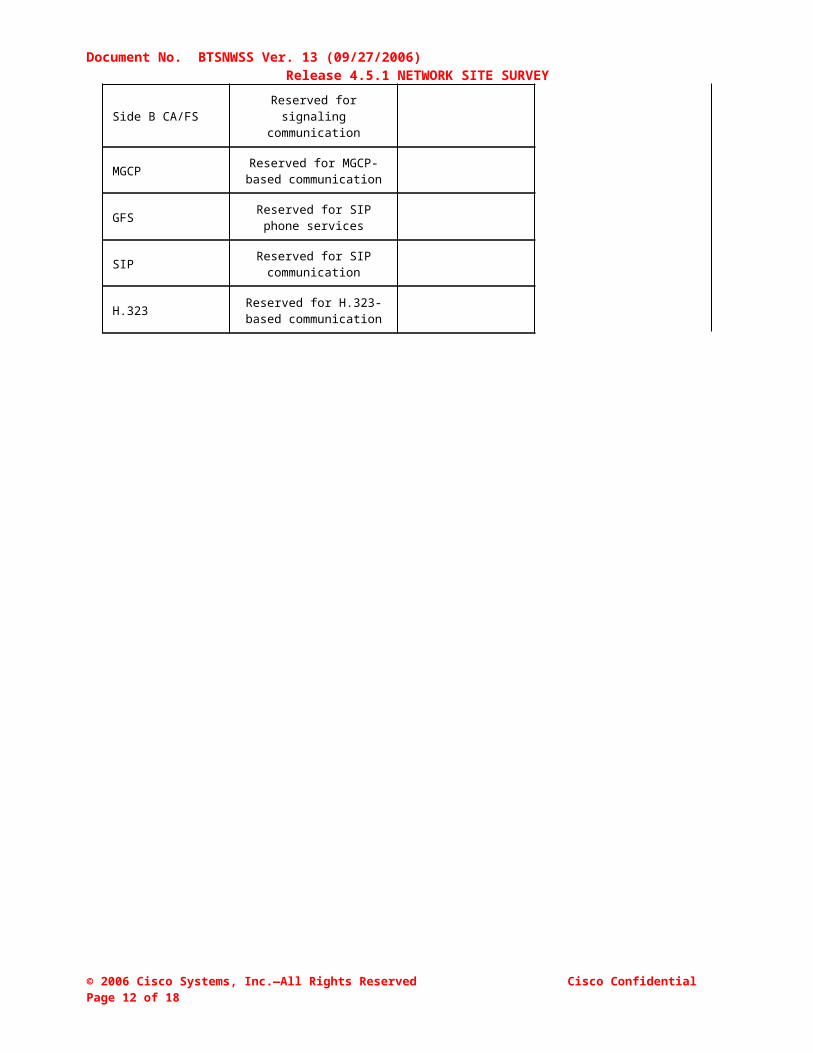
====SAMPLE====CONFIGURATION DATA FOR SIGNALLING NETWORKS
Two external networks are required for signalling communication with network entities such as DNS, ITP and VoIP signaling gateways.
Note – In the table below, GFS = GUI Feature Server.
See the figure 1 and 2 regarding redundancy requirements for connections between the Cisco BTS 10200 Softswitch and external network elements.
1st Signalling Network:
Host/Signalling Description
Description IP AddressIP Address of Default
GatewayEnter one IP address
(This interface must be IRDP enabled)
Side A CA/FS Reserved for signaling communication
10.89.225.12
10.89.225.254
Side B CA/FS Reserved for remote management
10.89.225.13
MGCP Reserved for MGCP-based communication
10.89.225.14
GFS Reserved for SIP phone services
10.89.225.15
SIP Reserved for SIP communication
10.89.225.16
H.323 Reserved for H.323-based communication
10.89.225.17
2nd Signalling Network:
Host/Signalling Description
Description IP AddressIP Address of Default
GatewayEnter one IP address
(This interface must be IRDP enabled)
Side A CA/FS Reserved for signaling communication
10.89.226.12
10.89.226.254
Side B CA/FS Reserved for signaling communication
10.89.226.13
MGCP Reserved for MGCP-based communication
10.89.226.14
GFS Reserved for SIP phone services
10.89.226.15
SIP Reserved for SIP communication
10.89.226.16
H.323 Reserved for H.323-based communication
10.89.226.17
© 2006 Cisco Systems, Inc.—All Rights Reserved Cisco Confidential Page 15 of 18

Document No. BTSNWSS Ver. 13 (09/27/2006) Release 4.5.1 NETWORK SITE SURVEY
====SAMPLE====CONFIGURATION DATA FOR MBA HOST
The MBA (mini browser adaptor) host is used to interface with SIP phones for services. The services are available for users via the “Services” key on a SIP Phone.
Note: This host must be on a separate Sun host machine (see Figure 1) that is not part of standard Cisco BTS 10200 configuration.
MBA host name Management IP address Signalling IP address
mbaserver 10.89.233.14 10.89.225.18
CONFIGURATION DATA FOR INTERNAL (PRIVATE) NETWORKSix unused private nonroutable subnets in the 10.10.x range are required for internal communications between the CA/FS and EMS/BDMS. Cisco recommends using the following subnet default values, if these are not used elsewhere in your network:
10.10.120.x 10.10.121.x 10.10.122.x 10.10.123.x 10.10.124.x 10.10.125.x
Please indicate your selection below:
X The default values are acceptable. The default values are NOT acceptable.
Instead, use the following six subnets; these are NOT used elsewhere in the network:
1
2
3
4
5
6
4th octet of the IPs used by SIM, ASM, POTS (CA to FS communication)On the internal networks a set of IP addresses supports Call Agents to Feature Server communication. The octets used in the definitions below should not replicate entries existing in the same internal subnets.
Links Default IPs 4th octet of IP Address
SIM in Call Agent (CA to FS communication subnets).146 146
ASM in FSAIN (CA to FS communication subnets).205 205
POTS in FSPTC (CA to FS communication subnets).235 235
© 2006 Cisco Systems, Inc.—All Rights Reserved Cisco Confidential Page 16 of 18

Document No. BTSNWSS Ver. 13 (09/27/2006) Release 4.5.1 NETWORK SITE SURVEY
====SAMPLE====LOG ARCHIVE FACILITY
This feature is optional. In order to enable this feature, info must be provided about the external archive system, target directory and the disk quota (in Gigabytes) reserved for storage for each platform. Leaving all parameters blank will void this feature.Note: The following parameters are organized in groups of three. One group for each platform. To disable this feature for a given platform, each entry of the group must be left empty.
Parameter Value Comments
Enable LAF? Yes This flag determines whether LAF will be enabled or disabled in the system. Valid values are 'Yes’ (enabled) and 'No' (disabled – no need to fill the parameters below).
CA Archive System Server
logStorage Identifies the name of the external archival system used for the CallAgent trace-logs
CA archive directory full path name
/archive/BTS1-CA Full path name of the target directory used as repository for the CallAgent trace-logs.
CA disk Quota (in Gigabytes)
20 Disk quota reserved for CallaAgent trace-logs storage on the archival system (Gigabytes).
FSPTC Archive System Server
logStorage Identifies the name of the external archival system used for the FSPTC trace-logs
FSPTC archive directory full path name
/archive/BTS1-FSPTC Full path name of the target directory used as repository for the FSPTC trace-logs.
FSPTC disk Quota (in Gigabytes)
20 Disk quota reserved for FSPTC trace-logs storage on the archival system (Gigabytes).
FSAIN Archive System Server
logStorage Identifies the name of the external archival system used for the FSAIN trace-logs
FSAIN archive directory full path name
/archive/BTS1-FSAIN Full path name of the target directory used as repository for the FSAIN trace-logs.
FSAIN disk Quota (in Gigabytes)
20 Disk quota reserved for FSAIN trace-logs storage on the archival system (Gigabytes).
EMS Archive System Server
logStorage Identifies the name of the external archival system used for the EMS trace-logs
EMS archive directory full path name
/archive/BTS1-EMS Full path name of the target directory used as repository for the EMS trace-logs.
EMS disk Quota (in Gigabytes)
20 Disk quota reserved for EMS trace-logs storage on the archival system (Gigabytes).
BDMS Archive System Server
logStorage Identifies the name of the external archival system used for the BDMS trace-logs
BDMS archive directory full path name
/archive/BTS1-BDMS Full path name of the target directory used as repository for the BDSM trace-logs.
BDMS disk Quota (in Gigabytes)
20 Disk quota reserved for BDMS trace-logs storage on the archival system (Gigabytes).
© 2006 Cisco Systems, Inc.—All Rights Reserved Cisco Confidential Page 17 of 18

Document No. BTSNWSS Ver. 13 (09/27/2006) Release 4.5.1 NETWORK SITE SURVEY
====SAMPLE====
Automatic Shared Memory Backup Times
These are the the time of day values indicating when the Automatic Shared Memory Backup will be done for the CA, FSAIN, FSPTC, EMS and BDMS. The start time values should be staggered for each platform such that only one platform is performing the operation at any given time on a given host machine.
Parameter Value Comments
SharedMem Backup Start Time (CA)
default Valid values range from 21:00 to 04:45 with a granularity of 15 minutes (00,15,30,45).To apply default value (22:00) enter ‘default’.
SharedMem Backup Start Time (FSAIN)
default Valid values range from 21:00 to 04:45 with a granularity of 15 minutes (00,15,30,45).To apply default value (22:15) enter ‘default’.
SharedMem Backup Start Time (FSPTC)
default Valid values range from 21:00 to 04:45 with a granularity of 15 minutes (00,15,30,45).To apply default value (22:30) enter ‘default’.
SharedMem Backup Start Time (EMS)
default Valid values range from 21:00 to 04:45 with a granularity of 15 minutes (00,15,30,45).To apply default value (22:00) enter ‘default’.
SharedMem Backup Start Time (BDMS)
default Valid values range from 21:00 to 04:45 with a granularity of 15 minutes (00,15,30,45).To apply default value (22:15) enter ‘default’.
© 2006 Cisco Systems, Inc.—All Rights Reserved Cisco Confidential Page 18 of 18

Document No. BTSNWSS Ver. 13 (09/27/2006) Release 4.5.1 NETWORK SITE SURVEY
NETWORK REDUNDANCY AND PATH DIVERSITY EXAMPLESNote: The drawing on this page shows logical connections.
"To support full system redundancy, it is necessary to connect the external uplinks from the Cisco BTS 10200 Softswitch as shown in Figure 2, with diverse routing paths to the related external network elements (NEs) and services (such as OSS, DNS, media gateways, and announcement servers). CAUTION: If this is not done, a single point of failure could cause a traffic interruption.
To ensure redundancy of the DNS lookup function in the event of a network outage, it is strongly recommended that the two DNS units be reachable via separate networks with diverse routing paths.CAUTION: If both DNS servers become unreachable, a traffic interruption will occur.
EXAMPLE of Cisco BTS 10200 Softswitch communication with external network elements in the service provider network:
Figure 2:
Notes:1. The uplinks for external communications are used primarily for DNS services and VoIP signaling based on protocols such as MGCP, SIP, H.323, and so forth.
Acronyms:VoIP = Voice over IPSSH = Secure ShellSFTP = Secure FTPDNS = Domain Name ServerIRDP = Internet Control Message Protocol (ICMP) Router Discovery Protocol
© 2006 Cisco Systems, Inc.—All Rights Reserved Cisco Confidential Page 19 of 18

Document No. BTSNWSS Ver. 13 (09/27/2006) Release 4.5.1 NETWORK SITE SURVEY
Corporate HeadquartersCisco Systems, Inc.170 West Tasman DriveSan Jose, CA 95134-1706USAwww.cisco.comTel: 408 526-4000 800 553-NETS (6387)
Fax: 408 526-4100
European HeadquartersCisco Systems International BVHaarlerbergparkHaarlerbergweg 13-191101 CH AmsterdamThe Netherlandswww-europe.cisco.comTel: 31 0 20 357 1000Fax: 31 0 20 357 1100
Americas HeadquartersCisco Systems, Inc.170 West Tasman DriveSan Jose, CA 95134-1706USAwww.cisco.comTel: 408 526-7660Fax: 408 527-0883
Asia Pacific HeadquartersCisco Systems, Inc.Capital Tower138 Robinson Road#22-01 to #29-01 Singapore 068912www.cisco.comTel: +65 6317 7777Fax: +65 6317 7799
Cisco Systems has more than 200 offices in the following countries and regions. Addresses, phone numbers, and fax numbers are listed on the Cisco Web site at www.cisco.com/go/offices.
Argentina • Australia • Austria • Belgium • Brazil • Bulgaria • Canada • Chile • China PRC • Colombia • Costa Rica Croatia • Czech Republic • Denmark • Dubai, UAE • Finland • France • Germany • Greece • Hong Kong SAR • HungaryIndia • Indonesia • Ireland • Israel • Italy • Japan • Korea • Luxembourg • Malaysia • Mexico • The NetherlandsNew Zealand • Norway • Peru • Philippines • Poland • Portugal • Puerto Rico • Romania • Russia • Saudi ArabiaScotland • Singapore • Slovakia • Slovenia • South Africa • Spain • Sweden • Switzerland • Taiwan • Thailand • Turkey Ukraine • United Kingdom • United States • Venezuela • Vietnam • Zimbabwe
THE SPECIFICATIONS AND INFORMATION REGARDING THE PRODUCTS IN THIS MANUAL ARE SUBJECT TO CHANGE WITHOUT NOTICE. ALL STATEMENTS, INFORMATION, AND RECOMMENDATIONS IN THIS MANUAL ARE BELIEVED TO BE ACCURATE BUT ARE PRESENTED WITHOUT WARRANTY OF ANY KIND, EXPRESS OR IMPLIED. USERS MUST TAKE FULL RESPONSIBILITY FOR THEIR APPLICATION OF ANY PRODUCTS.
THE SOFTWARE LICENSE AND LIMITED WARRANTY FOR THE ACCOMPANYING PRODUCT ARE SET FORTH IN THE INFORMATION PACKET THAT SHIPPED WITH THE PRODUCT AND ARE INCORPORATED HEREIN BY THIS REFERENCE. IF YOU ARE UNABLE TO LOCATE THE SOFTWARE LICENSE OR LIMITED WARRANTY, CONTACT YOUR CISCO REPRESENTATIVE FOR A COPY.
The Cisco implementation of TCP header compression is an adaptation of a program developed by the University of California, Berkeley (UCB) as part of UCB’s public domain version of the UNIX operating system. All rights reserved. Copyright © 1981, Regents of the University of California.
NOTWITHSTANDING ANY OTHER WARRANTY HEREIN, ALL DOCUMENT FILES AND SOFTWARE OF THESE SUPPLIERS ARE PROVIDED “AS IS” WITH ALL FAULTS. CISCO AND THE ABOVE-NAMED SUPPLIERS DISCLAIM ALL WARRANTIES, EXPRESSED OR IMPLIED, INCLUDING, WITHOUT LIMITATION, THOSE OF MERCHANTABILITY, FITNESS FOR A PARTICULAR PURPOSE AND NONINFRINGEMENT OR ARISING FROM A COURSE OF DEALING, USAGE, OR TRADE PRACTICE.
IN NO EVENT SHALL CISCO OR ITS SUPPLIERS BE LIABLE FOR ANY INDIRECT, SPECIAL, CONSEQUENTIAL, OR INCIDENTAL DAMAGES, INCLUDING, WITHOUT LIMITATION, LOST PROFITS OR LOSS OR DAMAGE TO DATA ARISING OUT OF THE USE OR INABILITY TO USE THIS MANUAL, EVEN IF CISCO OR ITS SUPPLIERS HAVE BEEN ADVISED OF THE POSSIBILITY OF SUCH DAMAGES.
CCIP, CCSP, the Cisco Arrow logo, the Cisco Powered Network mark, Cisco Unity, Follow Me Browsing, FormShare, and StackWise are trademarks of Cisco Systems, Inc.; Changing the Way We Work, Live, Play, and Learn, and iQuick Study are service marks of Cisco Systems, Inc.; and Aironet, ASIST, BPX, Catalyst, CCDA, CCDP, CCIE, CCNA, CCNP, Cisco, the Cisco Certified Internetwork Expert logo, Cisco IOS, the Cisco IOS logo, Cisco Press, Cisco Systems, Cisco Systems Capital, the Cisco Systems logo, Empowering the Internet Generation, Enterprise/Solver, EtherChannel, EtherSwitch, Fast Step, GigaStack, Internet Quotient, IOS, IP/TV, iQ Expertise, the iQ logo, iQ Net Readiness Scorecard, LightStream, MGX, MICA, the Networkers logo, Networking Academy, Network Registrar, Packet, PIX, Post-Routing, Pre-Routing, RateMUX, Registrar, ScriptShare, SlideCast, SMARTnet, StrataView Plus, Stratm, SwitchProbe, TeleRouter, The Fastest Way to Increase Your Internet Quotient, TransPath, and VCO are registered trademarks of Cisco Systems, Inc. and/or its affiliates in the United States and certain other countries.
All other trademarks mentioned in this document or Website are the property of their respective owners. The use of the word partner does not imply apartnership relationship between Cisco and any other company. (0401R)
© 2006 Cisco Systems, Inc.—All Rights Reserved Cisco Confidential Page 20 of 18