Embed Size (px)
Citation preview
Netgroup, Nov 19 2004 MPLS Application Scenarios for INFN 1
MPLS: Application Scenarios for INFN
Netgroup Meeting
Nov 19 2004

Netgroup, Nov 19 2004 MPLS Application Scenarios for INFN 2
Outline
• Introduction to MPLS
• MPLS VPNs
• MPLS DiffServ
• GMPLS
• Scenarios
• Some experimental results

Netgroup, Nov 19 2004 MPLS Application Scenarios for INFN 3
MPLS Overview• In a network based on a connectionless network layer protocol, each router makes
an independent forwarding decision for that packet. That is, each router analyzes the packet's header, and each router runs a network layer routing algorithm. Each router independently chooses a next hop for the packet, based on its analysis of the packet's header and the results of running the routing algorithm.
• Choosing the next hop can therefore be thought of as the composition of two functions.
– The first function partitions the entire set of possible packets into a set of "Forwarding Equivalence Classes (FECs)".
– The second maps each FEC to a next hop. All packets which belong to a particular FEC and which travel from a particular node will follow the same path.
• In conventional IP forwarding, a particular router will typically consider two packets to be in the same FEC if there is some address prefix X in that router's routing tables such that X is the "longest match" for each packet's destination address. As the packet traverses the network, each hop in turn reexamines the packet and assigns it to a FEC.
• In MPLS, the assignment of a particular packet to a particular FEC is done just once, as the packet enters the network.
– The FEC to which the packet is assigned is encoded as a short fixed length value known as a "label".
– In the MPLS forwarding paradigm, once a packet is assigned to a FEC, no further header analysis is done by subsequent routers; all forwarding is driven by the labels.
Netgroup, Nov 19 2004 MPLS Application Scenarios for INFN 4
Advantages
• MPLS forwarding can be implemented by switches responsible of doing label lookup and replacement (but not capable of supporting routing)
• the ingress router may use, in determining the assignment, any information it has about the packet, even if that information cannot be gleaned from the network layer header (e.g. packets arriving on different ports may be assigned to different FECs). Conventional forwarding, on the other hand, can only consider information which travels with the packet in the packet header.
• Sometimes it is desirable to force a packet to follow a particular route which is explicitly chosen at or before the time the packet enters the network, rather than being chosen by the normal dynamic routing algorithm as the packet travels (e.g. to support traffic engineering). In conventional forwarding, this requires the packet to carry an encoding of its route along with it ("source routing"). In MPLS, a label can be used to represent the route.
• The packet label can also determine a packet's "precedence" or "class of service". In this case, the label represents the combination of a FEC and a precedence or class of service.

Netgroup, Nov 19 2004 MPLS Application Scenarios for INFN 5
Some terminology
Label : a short fixed length physically contiguous identifier which is used to identify a FEC, usually of local significance.
Label merging: the replacement of multiple incoming labels for a particular FEC with a single outgoing label.
MPLS domain: a contiguous set of nodes which operate MPLS routing and forwarding and which are also in one Routing orAdministrative Domain.
Labeled packet: is a packet into which a label has been encoded.– The label can reside in an encapsulation header which exists specifically for
this purpose.
– The label may reside in an existing data link or network layer header, as long as there is a field which is available for that purpose. The particular encoding technique to be used must be agreed to by both the entity which encodes the label and the entity which decodes the label.
Label distribution protocol: a set of procedures by which one LSR informs another of the label/FEC bindings it has made. Several LDP protocols can coexist.

Netgroup, Nov 19 2004 MPLS Application Scenarios for INFN 6
Label
IPv4 Packet MPLS Hdr
Prec: xyz Prec: xyz
Non-MPLS Domain
MPLS Domain
0 1 2 30 1 2 3 4 5 6 7 8 9 0 1 2 3 4 5 6 7 8 9 0 1 2 3 4 5 6 7 8 9 0 1+-+-+-+-+-+-+-+-+-+-+-+-+-+-+-+-+-+-+-+-+-+-+-+-+-+-+-+-+-+-+-+-+
+-+-+-+-+-+-+-+-+-+-+-+-+-+-+-+-+-+-+-+-+-+-+-+-+-+-+-+-+-+-+-+-+
| Label | EXP |S| TTL |

Netgroup, Nov 19 2004 MPLS Application Scenarios for INFN 7
Some terminology (cont)
• LDPs:– Piggypacking of label information on BGP-4– Constraint-Based LSP Setup using LDP– LDP Specification– Extensions to RSVP for LSP Tunnel
• Label stack: labeled packet carries a number of labels, organized as a last-in, first-out stack.
• Next Hop Label Forwarding Entry: used when forwarding a labeled packet. It contains the following information:1. the packet's next hop,2. the operation to perform on the packet's label stack; this is one of the
following operations:a) replace the label at the top of the label stack with a specified new label,b) pop the label stack, c) replace the label at the top of the label stack with a specified new label, and then
push one or more specified new labels onto the label stack.It may also contain:d) the data link encapsulation to use when transmitting the packete) the way to encode the label stack when transmitting the packet.

Netgroup, Nov 19 2004 MPLS Application Scenarios for INFN 8
Generic MPLS Encapsulation
• One way to encode the label stack is to define a new protocol to be used as a "shim" between the data link layer and network layer headers.
• This shim would really be just an encapsulation of the network layer packet;
• it would be "protocol-independent" such that it could be used to encapsulate any network layer. Hence we will refer to it as the "generic MPLS encapsulation".

Netgroup, Nov 19 2004 MPLS Application Scenarios for INFN 9
Aggregation
One way of partitioning traffic into FECs is to create a separate FEC for each address prefix which appears in the routing table. However, within a particular MPLS domain, this may result in a set of FECs such that all traffic in all those FECs follows the same route.
For example, a set of distinct address prefixes might all have the same egress node, and label swapping might be used only to get the traffic to the egress node. In this case, within the MPLS domain, the union of those FECs is itself a FEC.
The procedure of binding a single label to a union of FECs which is itself a FEC (within some domain), and of applying that label to all traffic in the union, is known as "aggregation".
Aggregation may reduce the number of labels which are needed to handle a particular set of packets, and may also reduce the amount of label distribution control traffic needed.
Netgroup, Nov 19 2004 MPLS Application Scenarios for INFN
MPLS Virtual Private Networks
10
Netgroup, Nov 19 2004 MPLS Application Scenarios for INFN 11
Virtual Private Networks
• Definition:– “a generic term used to refer to the capability of
both private and public networks to support a communication infrastructure connecting geographically dispersed sites where users can communicate among them as if they were in a private network” (RFC 2764)

Netgroup, Nov 19 2004 MPLS Application Scenarios for INFN 12
Layer-3 to Layer-1 VPNs
• Layer-3: – They interconnect sets of hosts and routers based on Layer-3 addresses
(e.g. IP addresses)
• Layer-2:– They emulate the functionality of a Local Area Network in a wide area
environment
• Layer-1:– They connect a number of Customer Edge devices with point-to-point
connections operated at Layer-1, based either on optical or Time Division Multiplexing network infrastructures.

Netgroup, Nov 19 2004 MPLS Application Scenarios for INFN 13
Layer 2 -Virtual Private Services
• Customer traffic is mapped to a specific MPLS L2 VPN by configuiring L2 FEC based upon:– Input port ID
– VLAN ID
• Pseudo-wire: L2 point-to-point MPLS VPN
• Virtual Private LAN Services (VPLS) – provides connectivity to geographycally dispersed customers as if they
where connected to the LAN
– E.g. Ethernet 802.3 and VLAN 802.1q traffic
• Benefits:– No separate layer 2 equipment
– VPN service over an existing IP and MPLS backbone
• Interoperability issues (RSVP vs LDP)

Netgroup, Nov 19 2004 MPLS Application Scenarios for INFN 14
Layer 2 and 3 VPNs configuration
• Signalling protocol is enabled on Provider Edge routers;
• An IGP protocol on the PE and Provider Routers is configured;
• An IBGP session is configured between the PE routers;
• The vpn routing instance is configured on the PE router
• Deployed today as basis of the Managemed Bandwidth Service in GEANT
• LSP connections can be set up manually or dynamically (e.g. through RSVP, dynamic configuration not supported in the GEANT network).

Netgroup, Nov 19 2004 MPLS Application Scenarios for INFN
MPLS DiffServ
15Presentation_ID © 1999, Cisco Systems, Inc.
Netgroup, Nov 19 2004 MPLS Application Scenarios for INFN 16
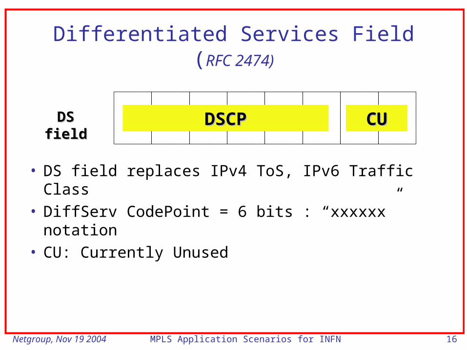
Differentiated Services Field (RFC 2474)
• DS field replaces IPv4 ToS, IPv6 Traffic Class
• DiffServ CodePoint = 6 bits : “xxxxxx” notation
• CU: Currently Unused
DSCPDSCP CUCUDS fieldDS field
Netgroup, Nov 19 2004 MPLS Application Scenarios for INFN 17
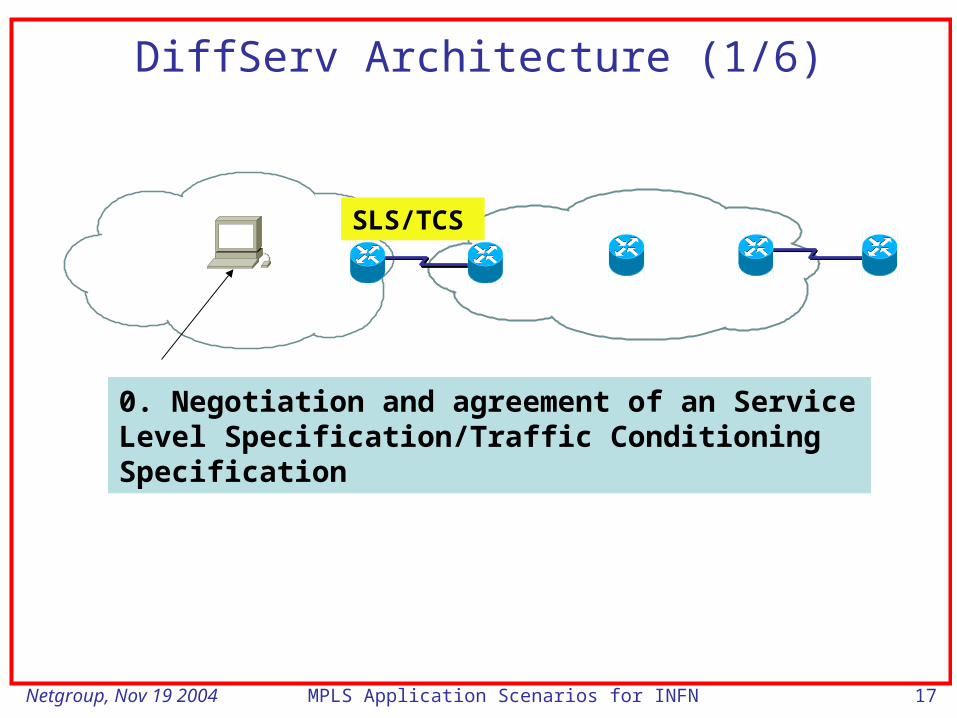
DiffServ Architecture (1/6)
0. Negotiation and agreement of an Service Level Specification/Traffic Conditioning Specification
SLS/TCS
Netgroup, Nov 19 2004 MPLS Application Scenarios for INFN 18
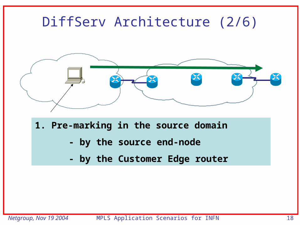
DiffServ Architecture (2/6)
1. Pre-marking in the source domain
- by the source end-node
- by the Customer Edge router

Netgroup, Nov 19 2004 MPLS Application Scenarios for INFN 19
DiffServ Architecture (3/6)
2. Egress- boundary DiffServ node of source domain applies traffic conditioning to ensure SLS/TCS compliance, hence causing possible re-marking, dropping and shaping
SLS/TCS

Netgroup, Nov 19 2004 MPLS Application Scenarios for INFN 20
DiffServ Architecture (4/6)
3. Classification according to SLS
4. Conditioning according to TCS
5. Assignment to a BA (DSCP setting)
SLS/TCS

Netgroup, Nov 19 2004 MPLS Application Scenarios for INFN 21
DiffServ Architecture (5/6)
6. Forwarding according to PHB mapped to set DSCP

Netgroup, Nov 19 2004 MPLS Application Scenarios for INFN 22
DiffServ Architecture (6/6)
If downstream DS domain support same service provisioning policy, same Per Hop Behaviours and DSCP/PHB mappings
Then 7: apply traffic conditioning to enforce SLS/TCS
Else 7’a: SLS’/TCS’ negotiation
7’b: Conditioning according to TCS’
SLS’/TCS’

Netgroup, Nov 19 2004 MPLS Application Scenarios for INFN 23
Colouring MPLS Frames
• Problem: at the ingress of an MPLS network how to convey information about the PHB associated to an incoming IP packet in order to preserve class membership information?
• Two methods are possible– EXP bits: they are part of the MPLS shim header; the mapping of DSCPs to EXP codes need to be defined
• convenient for Frame-based Interface
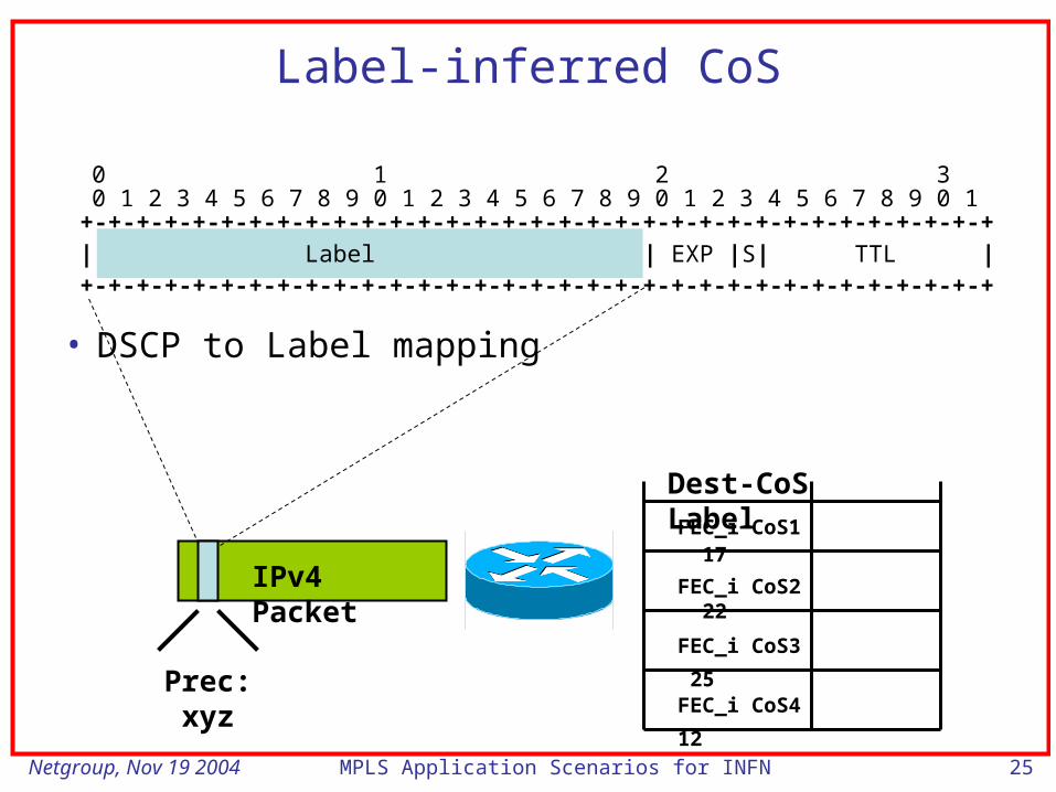
– MPLS label: for each Forwarding Equivalence Class, different MPLS labels are used to carry IP traffic associated to different Classes of Service
• convenient for ATM-based interface
Netgroup, Nov 19 2004 MPLS Application Scenarios for INFN 24
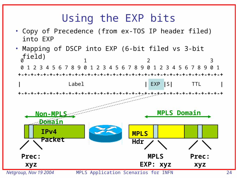
Using the EXP bits• Copy of Precedence (from ex-TOS IP header filed) into EXP
• Mapping of DSCP into EXP (6-bit filed vs 3-bit field)
IPv4 Packet MPLS Hdr
Prec: xyz Prec: xyzMPLS EXP: xyz
Non-MPLS Domain
MPLS Domain
0 1 2 30 1 2 3 4 5 6 7 8 9 0 1 2 3 4 5 6 7 8 9 0 1 2 3 4 5 6 7 8 9 0 1+-+-+-+-+-+-+-+-+-+-+-+-+-+-+-+-+-+-+-+-+-+-+-+-+-+-+-+-+-+-+-+-+
+-+-+-+-+-+-+-+-+-+-+-+-+-+-+-+-+-+-+-+-+-+-+-+-+-+-+-+-+-+-+-+-+
| Label | EXP |S| TTL |
Netgroup, Nov 19 2004 MPLS Application Scenarios for INFN 25
IPv4 Packet
Prec: xyz
FEC_i CoS1 17
FEC_i CoS2 22
FEC_i CoS3 25
FEC_i CoS4 12
Dest-CoS Label
0 1 2 30 1 2 3 4 5 6 7 8 9 0 1 2 3 4 5 6 7 8 9 0 1 2 3 4 5 6 7 8 9 0 1+-+-+-+-+-+-+-+-+-+-+-+-+-+-+-+-+-+-+-+-+-+-+-+-+-+-+-+-+-+-+-+-+
+-+-+-+-+-+-+-+-+-+-+-+-+-+-+-+-+-+-+-+-+-+-+-+-+-+-+-+-+-+-+-+-+| Label | EXP |S| TTL |
Label-inferred CoS
• DSCP to Label mapping

Netgroup, Nov 19 2004 MPLS Application Scenarios for INFN 26
GMPLS

Netgroup, Nov 19 2004 MPLS Application Scenarios for INFN 27
GMPLS Rationale• Need some control plane for OXCs
• Similarities between optical channels and traffic engineered LSPs suggest to use MPLS for OXCs
• MPLS control plane is standards-based and IP-centric
– Facilitate integration with IP routers & LSRs (paves way for incorporation of DWDM multiplexers on IP routers)
• Support traffic engineering functions
• Interoperability among diverse devices (routers, switches, ADMs, OXCs etc.)
• Provide standards based, multi-vendor interoperability within an optical transport network
Netgroup, Nov 19 2004 MPLS Application Scenarios for INFN 28
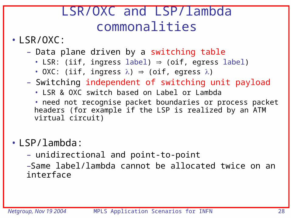
LSR/OXC and LSP/lambda commonalities
• LSR/OXC:– Data plane driven by a switching table
• LSR: (iif, ingress label) (oif, egress label)• OXC: (iif, ingress ) (oif, egress )
– Switching independent of switching unit payload• LSR & OXC switch based on Label or Lambda• need not recognise packet boundaries or process packet headers (for example if the LSP is realized by an ATM virtual circuit)
• LSP/lambda:– unidirectional and point-to-point –Same label/lambda cannot be allocated twice on an interface

Netgroup, Nov 19 2004 MPLS Application Scenarios for INFN
MPLS Network
Label Switching Routers(Router or ATM Switch)
Edge Label Switching Routers
Netgroup, Nov 19 2004 MPLS Application Scenarios for INFN 30
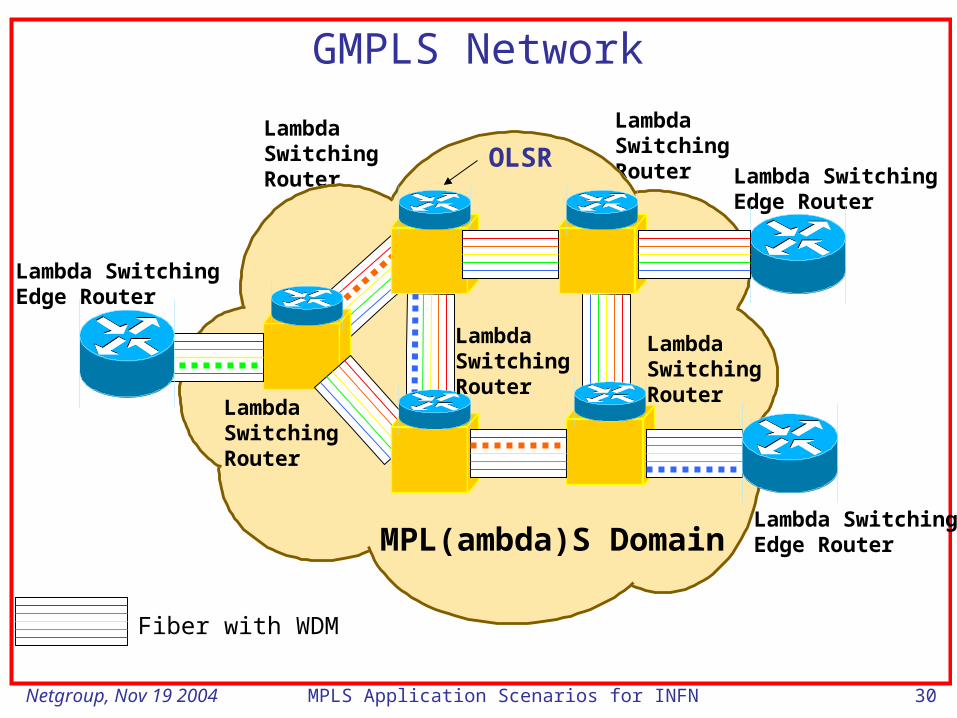
GMPLS Network
Lambda SwitchingEdge Router
Lambda SwitchingEdge Router
Lambda SwitchingEdge Router
LambdaSwitchingRouter
LambdaSwitchingRouter
MPL(ambda)S Domain
Fiber with WDM
LambdaSwitchingRouter
LambdaSwitchingRouter
LambdaSwitchingRouter
OLSR

Netgroup, Nov 19 2004 MPLS Application Scenarios for INFN 31
Optical Label Switch Router (OLSR)
OCP
OXC
IP Routing andSignaling
IP Routing andSignaling
DW
DM
DW
DM
• tightly-coupled OCP and OXC creates an Optical LabelSwitch Router
• runs IP and MPLS protocols - MPLaS, GMPLS• switches at Fiber and Lambda Level

Netgroup, Nov 19 2004 MPLS Application Scenarios for INFN 32
Three classes of OXCs
F-OXC
WR-OXC
WT-OXC
Fiber-to-fiber
Wavelengthrouting
Wavelengthtranslating

Netgroup, Nov 19 2004 MPLS Application Scenarios for INFN 33
GMPLS: Introduction• MPLS has been extended to include other LSR types whose
forwarding decisions are not based on packets but times slots, wavelengths or physical port numbers.
• Hence the notion of LSP has been generalized to:– FSC (fiber switch capable) LSP,
– LSC (Lambda Switch Capable) LSP,
– TDM LSP.
• LSP must start and end on LSR of the same type• New forms of labels are required (also called generalized label)
characterized by (see also next slide):– link protection type,
– LSP encoding,
– LSP payload.
Netgroup, Nov 19 2004 MPLS Application Scenarios for INFN 34
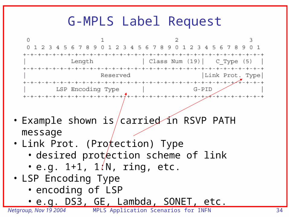
G-MPLS Label Request
• Example shown is carried in RSVP PATH message• Link Prot. (Protection) Type
• desired protection scheme of link• e.g. 1+1, 1:N, ring, etc.
• LSP Encoding Type• encoding of LSP• e.g. DS3, GE, Lambda, SONET, etc.

Netgroup, Nov 19 2004 MPLS Application Scenarios for INFN 35
G-MPLS Label
• Example shown is carried in RSVP RESV message• Link ID
• identifies which component link (out of several possible) that label will be allocated on
• Label• different formats for fiber, waveband, lambda, TDM and
packet

Netgroup, Nov 19 2004 MPLS Application Scenarios for INFN 36
Some G-MPLS Label Formats
SDH
Wavelength
Waveband

Netgroup, Nov 19 2004 MPLS Application Scenarios for INFN 37
Application scenarios

Netgroup, Nov 19 2004 MPLS Application Scenarios for INFN 38
1. Security and privacy
VPNs can offer security and privacy to applications (e.g. file transfers across Grids) even when relying on data-access protocols that do not guarantee integrity and confidentiality
– MPLS Layer-2/Layer-3VPNs can support data isolation by separating, for each VPN, the forwarding control plane, the signalling and the routing information in the intermediate forwarding devices
– In addition: with Layer-2 VPNs remote sparse resources can be connected as if they were part of the same LAN

Netgroup, Nov 19 2004 MPLS Application Scenarios for INFN 39
2. Quality of Service
VPNs can offer different traffic forwarding behaviors to traffic across the shared public infrastructure. This is achieved by associating a priority level to the traffic exchanged on specific tunnel instances and by enabling the differentiation mechanisms (Differentiated Services)
– Advantages (e.g. in case of Grid applications):• Guaranteed bandwidth (e.g. file transfer by deadline, virtual leased line)
• Virtual closeness realized between CEs and SEs in remote sites, thanks to the availability of QoS closeness has to be enabled in the Grid Information Service
• Resource discovery in job scheduling gives higher preference to compute resources that are close to the input data
• Efficient workload distribution: use of compute resources in small Grid sites
• Overall traffic load reduced at the Grid network bottlenecks
• and: traffic engineering

Netgroup, Nov 19 2004 MPLS Application Scenarios for INFN 40
3. High-speed point-to-point connections for HEP data replication (GMPLS – future)
Very high-speed connectivity between few well-defined Grid nodes can be used to assist the replication of large data files in a wide area Grid.
– The use of a dedicated high-speed communication channel avoids contention of multiple flows and improves the efficiency of reliable transport protocols such as TCP

Netgroup, Nov 19 2004 MPLS Application Scenarios for INFN 41
Experimental activities
Netgroup, Nov 19 2004 MPLS Application Scenarios for INFN 42
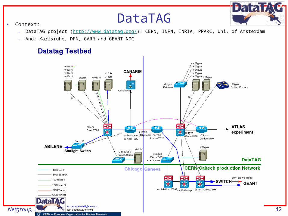
DataTAG• Context:
– DataTAG project (http://www.datatag.org/): CERN, INFN, INRIA, PPARC, Uni. of Amsterdam
– And: Karlsruhe, DFN, GARR and GEANT NOC

Netgroup, Nov 19 2004 MPLS Application Scenarios for INFN 43
Physical network set-up (DataTAG demo)
DataTAGCNAF
GARR GÉANT DataTagCERN
GARRBackup line
2.4 Gbps
CERNBackup line
2.4 Gbps
......
Dedicated 1 GEthernet interface

Netgroup, Nov 19 2004 MPLS Application Scenarios for INFN 44
MPLS-Based Layer-2 VPNs
• Ethernet/VLAN traffic is carried by MPLS over the service provide network (PE and P routers) and then converted back to L2 format at the rx site
• CE: it selects the output circuit to which specific L2 traffic has to be sent according to:– the VLAN ID in the 802.1Q frame header (VLAN L2 VPN)
– the input interface form which the frame was received (Ethernet L2 VPN)
• Juniper, Circuit cross-conenct encapsulation

Netgroup, Nov 19 2004 MPLS Application Scenarios for INFN 45
Example
SE1,1
SE1,2
CE1,1
CE1,2
CE1,3
SE2,1
SE2,2
CE2,1
CE2,2
SE3,1
SE3,2
CE3,1
CE3,2
SE3,3
SE3,4
Grid Domain 1
Grid Domain 3
Grid Domain 2
CE3,3
CE3,4
VLAN X
VLAN Y
Netgroup, Nov 19 2004 MPLS Application Scenarios for INFN 46
Why MPLS?
• Interest in testing the technology
• A given host can belong to one or more VPNs at a time if native VLAN tagging is enabled
• The LSP primary/secondary path can apply non-standard routing policies
• A given diffserv packet forwarding treatment can be assigned to the LSPs associated to a given VPN (MPLS EXP field set by the LSP head-end router):– Grid ftp between SEs: if based on enhanced TCP stacks, it can be handled through the
Scavenger/Less Than Best Effort service (fairness)
– CEs/SEs used for remote visualization with real-time requirements could apply to the IP Premium service
– Performance guarantees to individual VOs

Netgroup, Nov 19 2004 MPLS Application Scenarios for INFN 47
L2 VPNs and DataTAG:Dynamic Layer-2 VPN configuration
C7609T320T320
stm64
C7606M10M10
3com
VLAN1, IP Premium
VLAN2 LBE/Scavenger
Adv Res&Resource Mgr/Grid Information Service

Netgroup, Nov 19 2004 MPLS Application Scenarios for INFN 48
Diffserv/MPLS Path Elements
JuniperM10
JuniperM10
GÉANT
LBE, 1-1000 Mbps MPLS
IP Premium, 300 Mbps, MPLS
CERN
Congestionpoint

Netgroup, Nov 19 2004 MPLS Application Scenarios for INFN 49
L2 dynamic VPNs
JuniperM10
JuniperM10
GARR GÉANT
3com C7606
Grid014f, 131.154.99.104
Datagrid4, 131.154.99.68
Datagrid1, 131.154.99.32 w01gva
w04gva
Eth1192.91.239.21
Eth0192.168.1.1
Eth1192.91.238.102
Eth1192.91.238.104
Eth0192.91.239.4
ge-1/0/0so-0/0/0ge-0/0/0ge-0/1/0
Eth1192.168.1.2
VLAN 570192.91.239.0/26IP Premium
VLAN 571 192.91.238.96/27, LBE
VLAN 670192.168.1.0/24IP Premium
User interface, GRIS, AA,MPLS Manager
fe-1/1/1
fe-1/1/1
Netgroup, Nov 19 2004 MPLS Application Scenarios for INFN 50
Reservation phases
1. Submission of user request through interface
2. Matchmaking, i.e. selection of resources (Path list) that satisfy the requests. Match on:
– Path service (IP Premium, Less Than Best Effort, Best-effort)
– Path type (Diffserv, Mpls, Lightpath)
– Bandwidth (Path max bandwidth ≥ requested bandwidth)
– Src/Dst host in Path Src/Dst domain
3. Authentication and authorization (Globus Gatekeeper of Path Element)
4. MPLS Manager:1. Check for availability of resources over time
2. Router configuration when reservation starts1. Create/modify/destroy

Netgroup, Nov 19 2004 MPLS Application Scenarios for INFN 51
MPLS label switch paths and related connections
JuniperM10
JuniperM10
Grid014f
Datagrid4
Datagrid1 w01gva
w04gva
Eth1192.91.239.21
Eth0192.168.1.1
Eth1192.91.238.102
Eth1192.91.238.104
Eth0192.91.239.4
ge-1/0/0ge-0/1/0
Eth1192.168.1.2
VLAN 570IP Premium
VLAN 571, LBE
VLAN 670IP Premium
User interface, GRIS, AA,MPLS Manager

Netgroup, Nov 19 2004 MPLS Application Scenarios for INFN 52
MPLS-based L2 VPN management: features
• MPLS LSP: – unidirectional
– based on a Diffserv path statically provisioned (IP Premium)
– Connects the two CE routers of the two leaf domains
– Shared by authorized users/applications generating traffic from the source domain
– diffserv paths that support MPLS capabilities (across MPLS-capable transit domains) are indicated by the information system

Netgroup, Nov 19 2004 MPLS Application Scenarios for INFN 53
MPLS-based L2 VPN management: implementation
• Two given CE routers of two different leaf domains are connected by a single diffserv path of a given type (IP Premium, lbe etc)
• Each MPLS/diffserv path is statically associated to a given pre-defined VLAN number
• VLAN tagging pre-configured statically on end-systems
• Router configuration:– Diffserv: marking and policing (IP Premium only) at the ingress router– MPLS L2 VPN: VLAN tagging and encapsulation, LSPs with QoS and
CCC Connections (Juniper) on the LSP head-end router
• Topology and routing: very difficult to mange dynamically!

Netgroup, Nov 19 2004 MPLS Application Scenarios for INFN 54
Router configuration
• MPLS L2 VPN Manager:– Perl application using Junoscript libraries (prototype for Juniper
routers)• Configuration script parsing
• possible operating system/configuration scripts mismatches
• configuration errors (rollback)
• Configuration add/modify/delete
• Configuration locking

Netgroup, Nov 19 2004 MPLS Application Scenarios for INFN 55
Conclusions & NRN requirements• Results:
– Optimal TCP performance on MPLS L2 VPNs between StarLight and CERN – 1 Gbps
– MPLS EXP field marking and classification: ok (Juniper)
– Diffserv scheduling: ok
• Requirements:– On-demand set-up of e2e MPLS LSPs (no stitching)
– Handling of MPLS EXP field for QoS

Netgroup, Nov 19 2004 MPLS Application Scenarios for INFN 56
Some references
• Multiprotocol Label Switching Architecture, RFC 3031, Jan 2001.
• Virtual Private LAN Service over MPLS, Lasserre, M. Et alt; work in progress.
• MPLS CoS, Clarence Filsfils, CISCO, 1999.
• Generalized MPLS Optical Control Plane, J.P. Vasseur, CISCO, 2000.