Embed Size (px)
Citation preview

NERI MOTORI s.r.l.
Via A. Fleming, 6/840017 San Giovanni in Persiceto - Bologna - ITALYTel. +39 051 6870911 - Fax +39 051 825858www.nerimotori. come-mail: [email protected]
BASIC LINE MOTORS CHARACTERISTICS
NERI MOTORI s.r.l. - Via A. Fleming, 6/8 - 40017 San Giovanni in Persiceto - Bologna - ITALYTel. +39 051 6870911 - Fax +39 051 825858 - www.nerimotori. com - e-mail: [email protected]
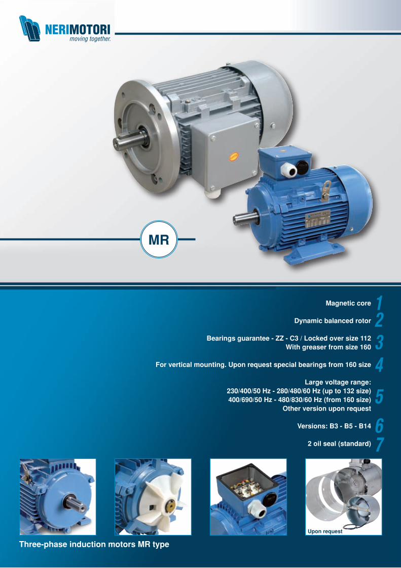
Three-phase induction motors MR type
MR
Upon request
1234
567
Magnetic core
Dynamic balanced rotor
Bearings guarantee - ZZ - C3 / Locked over size 112With greaser from size 160
For vertical mounting. Upon request special bearings from 160 size
Large voltage range:230/400/50 Hz - 280/480/60 Hz (up to 132 size)400/690/50 Hz - 480/830/60 Hz (from 160 size)
Other version upon request
Versions: B3 - B5 - B14
2 oil seal (standard)
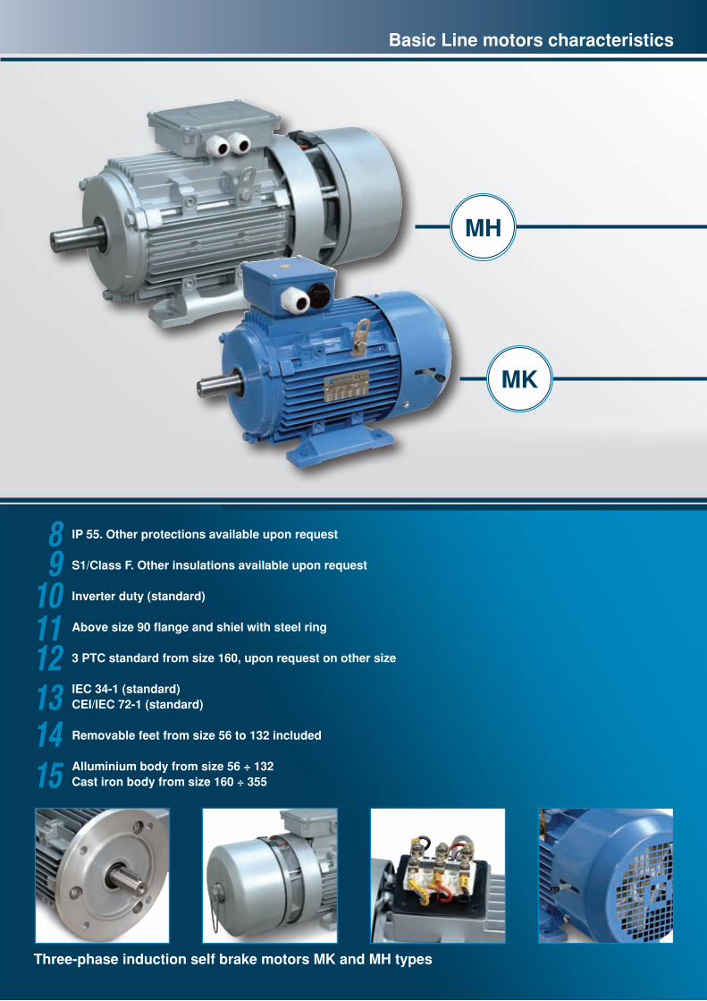
Three-phase induction self brake motors MK and MH types
MK
MH
Basic Line motors characteristics
89
101112131415
IP 55. Other protections available upon request
S1/Class F. Other insulations available upon request
Inverter duty (standard)
Above size 90 flange and shiel with steel ring
3 PTC standard from size 160, upon request on other size
IEC 34-1 (standard) CEI/IEC 72-1 (standard)
Removable feet from size 56 to 132 included
Alluminium body from size 56 ÷ 132Cast iron body from size 160 ÷ 355

UK_4
The Certification of the company qualitysystem conforms to ISO 9001 Standards (2000)
In line with company quality policy, NERI MOTORI is Certified conforming to ISO 9001 Standards (2000).The effort made in achieving this goal has resulted in constant improvements in product and Customer service.The management’s willingness to keep the Company at worldwide competitive levels has triggered a worthy process of improvement, in all the Company’s activities, with constant CUSTOMER SATISFACTION monitoring.This has been achieved thanks to investments made in the training of personnel, in the design and in the investments of machines and state-of-the-art technologies for tests at the initial stages, during production and during the final stage.
1
DICHIARAZIONE DI CONFORMITA’
Marchio CE
Neri Motori srl, dichiara che il materiale elettrico di cui si parla è conforme alle Direttive
Comunitarie: - D.M. 98/37/CE (Direttiva Macchine) e modifiche – Allegato IIB;
- B.T. 2006/95/CE (Bassa Tensione) e modifiche;
- E.M.C. 89/336/CEE (Compatibilità Elettromagnetica) e modifiche;
e che NON DEVE ESSERE MESSO IN FUNZIONE PRIMA DI ESSERE INCORPORATO
in una MACCHINA CE.
I motori elettrici trifase, tensione (0 - 690)Vac grandezza (IEC56 – IEC355), frequenza 50 Hz e 60
Hz Serie MR - Trifase per tutte le polarità
sono costruiti e provati in accordo ai seguenti Standard Internazionali:
- IEC 34-1 Prescrizioni generali per macchine elettriche rotanti;
- IEC 34-5 Classificazione gradi protezione macchine elettriche rotanti;
- IEC 34-6 Metodo ventilazione motori;
- IEC 34-7 Designazione forme costruttive e tipi di installazione;
- IEC 34-9 Limiti di rumorosità;
- IEC 38 Tensione sistemi B.T. ;
- IEC 72-1 Dimensioni e potenze nominali per macchine elettriche rotanti.
EMC i metodi di prova sono in accordo allo Standard EN-55014 (1994):
a) Prova condotta di picco nella banda 150kHz-30MHz;
b) Prova irradiata nella banda 30MHz-1GHz.
La NERI MOTORI DICHIARA ancora di essere certificata ISO 9001 (2000) con numero
IT – 13597 – IQNET.
Li 21/03/2008 . San Giovanni in Persiceto - Bologna – ITALIA
NERI MOTORI SRL
1
Declaration of Conformity CE Mark
Neri Motori srl, declares that the electrical material we are talking is in according to European Directives: - M.D. 98/37/EC (Machine directive) and modifications – Annex IIB; - L.V.D. 2006/95/EC (Low voltage directive) and modifications ; - E.M.C. 89/336/EC (Elettromagnetic compatibility) and modifications ; and MUST NOT RUN BEFORE ASSEMBLED in a CE MACHINERY.
Electric motors 3-ph, supply voltage (0 - 690)Vac, size (IEC56 – IEC355), frequency 50 hz and 60 hz MR Series – Three phase for all polarities
Are built and tested in according to the following Internationals Standards: - IEC 34-1 Electrical specifications; - IEC 34-5 Protection degrees; - IEC 34-6 Motor ventilation system; - IEC 34-7 Configurations; - IEC 34-9 Noise limits; - IEC 38 Standard Voltages ; - IEC 72-1 Sizes and dimensions. EMC Tests metods are in according to EN-55014 (1994) : a) Conduit test in the range (150kHz-30MHz); b) Irradiation test in the range (30MHz-1GHz).
NERI MOTORI declares to be certificated in according to ISO 9001 (2000) number IT – 13597 – IQNET. 21/03/2008 . San Giovanni in Persiceto - Bologna – ITALIA
NERI MOTORI SRL
1
AUTO DICHIARAZIONE CONFORMITA’ MOTORI ELETTRICI
ASINCRONI ATEX MARCATI IN TARGA CE – ATEX
PROTETTO DA CUSTODIA e/o ANTI SCINTILLA
GRUPPO II - CATEGORIA 3
La Neri Motori srl, in qualità di costruttore dichiara che il materiale elettrico di cui si parla,
MARCATO ATEX ,è conforme alle Direttive CEE:
- D.M. 98/37/CEE (Direttiva Macchine) e modifiche;
- B.T. 2006/95/CE (Bassa Tensione) e modifiche;
- E.M.C. 89/336/CEE (Compatibilità Elettromagnetica) e modifiche;
- ATEX 94/9/CE (Atmosfere potenzialmente esplosive);
- ROHS – 2002/95/CE (Sostanze pericolose).
I metodi di prova sono conformi alla Norma EN-55014 (1994) EMC:
a) Prova condotta di picco nella banda 150khz-30Mhz
b) Prova irradiata nella banda 30Mhz-1Ghz
La NERI MOTORI dichiara che il materiale elettrico è conforme agli Standard :
- CEI EN 60034-1 – Caratteristiche nominali e di funzionamento;
- IEC 61241 – 0 (Ed.2004-07) Polvere Combustibile - Requisiti Generali ;
- IEC 61241 – 1 (Ed.2004-05) Polvere Combustibile – Protezione tD ;
- CEI EN 60079-15 (Ed.2006-02) – Modo di protezione “nA”.
- Il corpo motore è provato e resiste a n.1 IMPATTO di 4 Joule;
- La prova di TEMPERATURA CARCASSA E’ STATA ESEGUITA CON INVOLUCRO
PULITO.
Per le ulteriori caratteristiche nominali si rimanda ai DATI DI TARGA es.:
- ZONA 2 (GAS) – Marcatura: EEx nA II T4 X IP55 ;
- ZONA 22 (DUST): 1) Marcatura (DUST NON CONDUTTIVO): Ex tD A22 IP55 135°C X.
2) Marcatura (DUST CONDUTTIVO): Ex tD A22 IP65 135°C X.
- ZONA2/22(GAS/DUST):
Marcatura: Ex tD A22 135°C - IP55/65 - EEx nA II T4 X
Per quanto riguarda il significato delle ZONE si ha:
- ZONA2 – Non probabile presenza di GAS esplosivo se presente di breve durata;
- ZONA22 – Non probabile presenza di POLVERE esplosiva se presente di breve durata;
Su richiesta esecuzioni per GAS e POLVERE e temperatura T3/T4/T5/T6.
Li San Giovanni in Persiceto (Bo) il 29 Febbraio 2008.
NERI MOTORI SRL
1
SELF DECLARATION OF CONFORMITY FOR ASYNCHRONE ELECTRIC ATEX MOTORS WITH CE-ATEX TYPEPLATE PROTECTED BY ENCLOSURE and/or ANTISPARK GROUP II – CATEGORY 3 NERI MOTORI SRL, as constructor, certifies that the electric material in object, with ATEX MARK, follows the CEE Directives : - M.D. 98/37/EC (Machine Directive) and following modifications; - L.V. 2006/95/EC (low tension) and following modifications; - E.M.C. 89/336/EC (Electromagnetic Compatibility) and following modifications; - ATEX 94/9/EC (Explosive Atmosphere); - ROHS – 2002/95/EC (Dangerous substances)
The test methods used are in according to EN -55014 Norms (1994) EMC: a) guided peak tests in the range 150khz-30Mhz b) radiated tests in the range 30Mhz-1Ghz NERI MOTORI SRL, declares that electric material is in according to Standards: - CEI EN 60034-1 – nominal and running features - IEC 61241 – 0 (Ed.2004-07) Combustible Dust – General requirements ; - IEC 61241 – 1 (Ed.2004-05) Combustible Dust – Protection tD ; - CEI EN 60079-15 (Ed.2006-02) – Type of protection “nA”. - The frame of the motor was tested and resists to n.1 impact of 4 Joule; - TEMPERATURE BODY TEST was performed with clean surface.
For further nominal characteristics see DETAILS ON TYPEPLATE i.e.: - ZONE 2 (GAS–G)– Marking: EEx nA II T4 X IP55 ; - ZONE22(DUST–D) :1) Marking (NOT CONDUCTIVE DUST): Ex tD A22 IP55 135°C X.2) Marking (CONDUCTIVE DUST): Ex tD A22 IP65 135°C X. - ZONE2/22(GAS/DUST) : Marking: Ex tD A22 135°C - IP55/65 - EEx nA II T4 X
Where means: ZONE 2 – if explosive GAS it’s present not stay for long time.ZONE 22 – if explosive DUST it’s present not stay for long time.On request are possible Motors for GAS and DUST with body temperature T3/T4/T5/T6. San Giovanni in Persicelo Date 29 Febbrary 2008 .
NERI MOTORI SRL
Marking
Per the provisions of the Machine Directive 89/392/EEC, the electric motor is a component that may not cause hazards to people, animals or property. The following directives are applied to this end:1) Low Voltage 2006/95/CE, according to which the electric motor is
“low-voltage electrical material”;2) Electromagnetic Compatibility 89/336/EEC.In compliance with these directives, type tests were carried out on Neri standard production; in particular, European Standard EN-60204-1 was applied for safety purposes. The European Standard EN-55014 (1994) was applied for EMC, carrying out:a) Guided peak tests in the 150 KHz - 30 MHz frequency range,b) Radiated tests in the 30 MHz-1 GHz frequency range.All of the production passed the tests or was modified to do so.The corresponding documentation is available from our headquarters and may be supplied upon request.
ATEX Motors - 94/9/CE
Neri Motori designs, produces, and self-certifies Atex Motors for zone 2 zone 22.Programmed third party body certification.
UK_5
Certifications
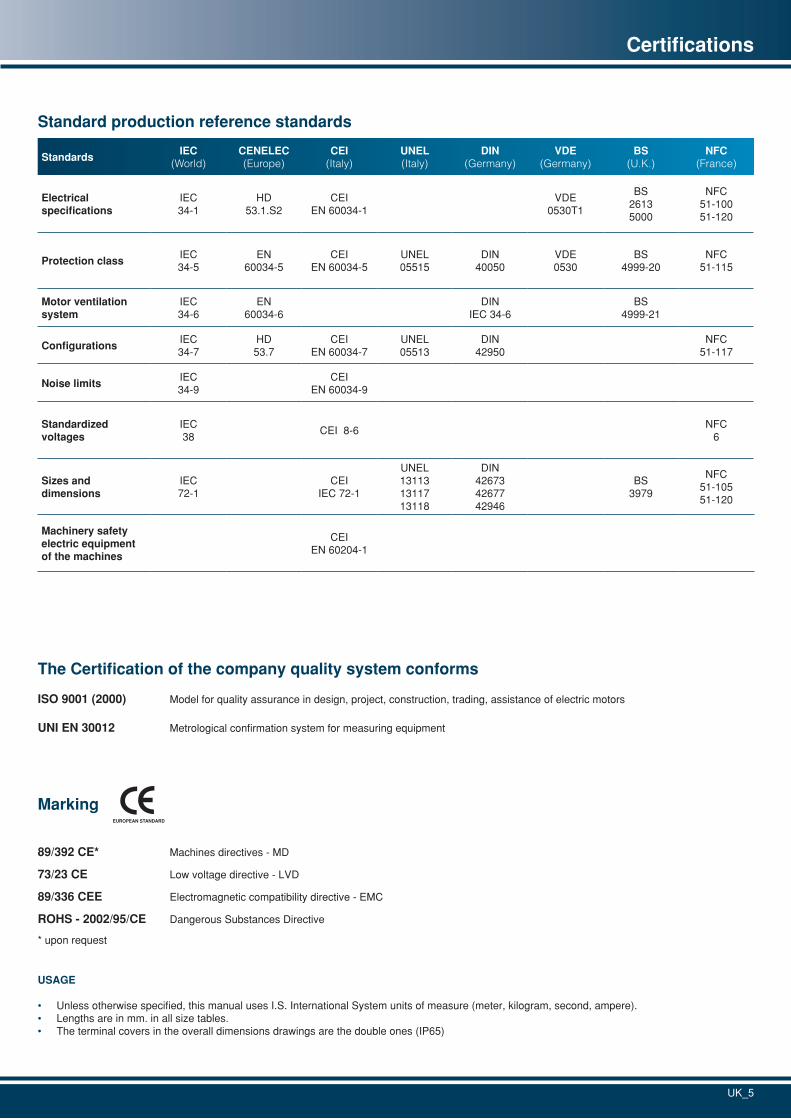
Standard production reference standards
StandardsIEC
(World)CENELEC(Europe)
CEI(Italy)
UNEL(Italy)
DIN(Germany)
VDE(Germany)
BS(U.K.)
NFC(France)
Electrical specifications
IEC34-1
HD53.1.S2
CEIEN 60034-1
VDE0530T1
BS 26135000
NFC51-10051-120
Protection classIEC34-5
EN60034-5
CEIEN 60034-5
UNEL05515
DIN40050
VDE0530
BS4999-20
NFC51-115
Motor ventilation system
IEC34-6
EN60034-6
DINIEC 34-6
BS4999-21
ConfigurationsIEC34-7
HD53.7
CEIEN 60034-7
UNEL05513
DIN42950
NFC51-117
Noise limitsIEC34-9
CEIEN 60034-9
Standardized voltages
IEC38
CEI 8-6NFC
6
Sizes and dimensions
IEC72-1
CEIIEC 72-1
UNEL131131311713118
DIN426734267742946
BS3979
NFC51-10551-120
Machinery safety electric equipmentof the machines
CEIEN 60204-1
The Certification of the company quality system conforms
ISO 9001 (2000) Model for quality assurance in design, project, construction, trading, assistance of electric motors
UNI EN 30012 Metrological confirmation system for measuring equipment
Marking
89/392 CE* Machines directives - MD
73/23 CE Low voltage directive - LVD
89/336 CEE Electromagnetic compatibility directive - EMC
ROHS - 2002/95/CE Dangerous Substances Directive
* upon request
USAGE
• Unless otherwise specified, this manual uses I.S. International System units of measure (meter, kilogram, second, ampere).• Lengths are in mm. in all size tables.• The terminal covers in the overall dimensions drawings are the double ones (IP65)
UK_6
Description Dimension Tolerance
Shaft diameter D
≤ ø 28 mm j6
ø 32 mm ÷ ø 48 mm k6
ø 55 mm ÷ ø 110 mm m6
CEI IEC 72-1 Standardized keys
F h9
G2 mm ÷ 6 mm h9
7 mm ÷ 16 mm h11
CEI IEC 72-1 Standardized flanges N ≤ ø 450 mm j6
Axis height per CEI IEC 72-1 H +0 ÷ -0.5 mm
Shaft stop E +0 ÷ -0.2 mm
Technical specifications
The electric motors covered by this catalogue are constructed and tested in accordance with the IEC Norms which implement the most important EEC European Directives in the electrical engineering sector.All the induction motors we produce have die-cast squirrel cage motor and wound stator, are enclosed and have external cooling to IEC 34-6 (IC 411).
The power supply voltages of the standard motors in the catalogue comply with IEC 38 (1983) and CEI-8-6 (March 1990):230V/400V/50Hz for the three-phase models with permissible variation of ±10% of the rated voltage.All electrical and mechanical specifications, as well as the testing methods, comply with IEC 34-1 and CEI EN 60034-1.
The output powers and machine sizes comply with CEI IEC 72-1, while construction forms B3, B5 and B14 are to IEC 34-7.All geometrical dimensions are standardized in accordance with the UNEL tables 13113-71, 13117-71, 13118-71/CEI IEC 72-1.
The degrees of protection of the casings comply with CEI EN 60034-5.Our standard motors have IP 55 protection and are insulated overall in class F to IEC 34-1 and CEI EN 60034-1.
As standard, the drive shafts and tangs have dimensions and tolerances to CEI IEC 72-1.Standard shafts are constructed in C43/C40 steel.
We use preloaded bearing rings of the best makes, which our company considers reliable.
Motors are manufactured for standard S1 service, other executions on request.
Mechanical specifications
Wound StatorsHigh-quality magnetic sheet metals are used for most of the production, to ensure constant high performance.The copper used is impregnated with a double layer of insulating enamel to ensure high resistance to electrical, thermal and mechanical stress.The standard insulation class of the motor is F, may be supplied upon agreement with the manufacturer.
The ambient temperature considered is 40 °C.Tropicalization processes are available through impregnation with paints having high hygroscopic qualities, for use in areas with high ambient humidity >60% R.H.
Rotors (tropicalized)These are die-cast alluminium squirrel-cage rotors.
KeysThese are made of C40 steel with dimensions standardized per CEI IEC 72-1. The thread diameters of standard shafts, in compliance with standard DIN 332. Body according CEI-IEC 72-1.
Frame (per CEI-IEC 72-1)Die-cast alluminium with high mechanical capacity, good thermal conductivity, and very lightweight.Frames are available in a version with standard tie-rods, with studs upon request.
Motor terminal boardFor the B3 frame with feet, the terminal board is placed on top in standard production, or may be placed on the right or left side upon request.
Flanges and shields (per CEI-IEC 72-1)Standard dimensions per CEI-IEC 72-1.From size 56 to 132 are in alluminium, while from size 160 to 355 cast iron.
Cooling (per IEC 34-6 and EN 60034-6)Obtained by means of a two-way rotary fan with radial blades keyed onto the motor shaft IC 411.Made of plastic, it has a high operating temperature of 100°C.For applications with electronic controls such as inverters, assisted power cooling is available via an auxiliary cooling-type motor IC416, also in kit form.
Fan coverRealized in painted sheet.
Noise level (CEI EN 60034-9)Sound pressure and power levels were measured on single- and three-phase motors, one meter away from the machine, and weighted according to curve A (ISO R 1680). At 50 Hz for relative values at 60 Hz, this increases by an average of 4 dbA.
Mechanical tolerances (per CEI-IEC 72-1)Table shows the mechanical tolerances where the motor is keyed with the load.
UK_7
Technical and mechanical specifications
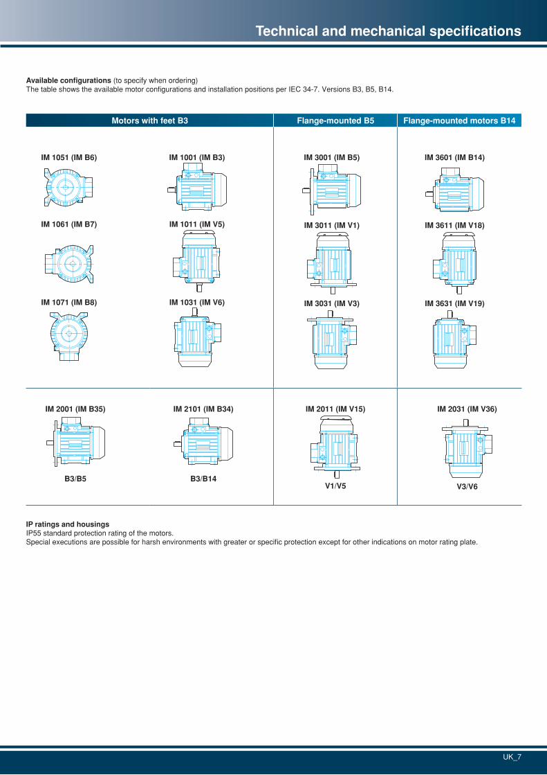
Available configurations (to specify when ordering)The table shows the available motor configurations and installation positions per IEC 34-7. Versions B3, B5, B14.
IP ratings and housingsIP55 standard protection rating of the motors.Special executions are possible for harsh environments with greater or specific protection except for other indications on motor rating plate.
Motors with feet B3 Flange-mounted B5 Flange-mounted motors B14
IM 1071 (IM B8) IM 1031 (IM V6)
IM 1011 (IM V5)IM 1061 (IM B7)
IM 1051 (IM B6) IM 1001 (IM B3)
IM 3631 (IM V19)
IM 3611 (IM V18)
IM 3601 (IM B14)
IM 2101 (IM B34)IM 2001 (IM B35)
B3/B14B3/B5
IM 2011 (IM V15)
V1/V5
IM 2031 (IM V36)
V3/V6
IM 3031 (IM V3)
IM 3011 (IM V1)
IM 3001 (IM B5)
UK_8
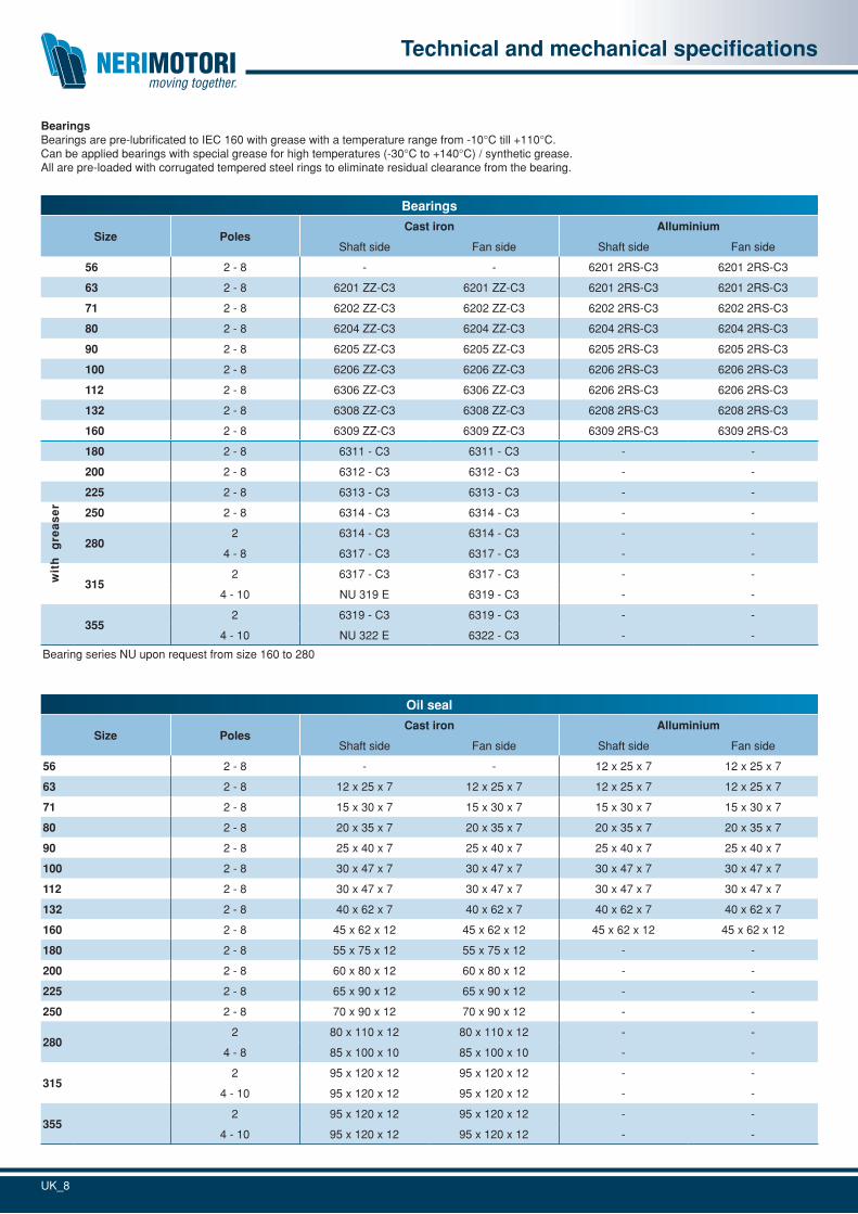
BearingsBearings are pre-lubrificated to IEC 160 with grease with a temperature range from -10°C till +110°C.Can be applied bearings with special grease for high temperatures (-30°C to +140°C) / synthetic grease.All are pre-loaded with corrugated tempered steel rings to eliminate residual clearance from the bearing.
Bearings
Size PolesCast iron Alluminium
Shaft side Fan side Shaft side Fan side
56 2 - 8 - - 6201 2RS-C3 6201 2RS-C3
63 2 - 8 6201 ZZ-C3 6201 ZZ-C3 6201 2RS-C3 6201 2RS-C3
71 2 - 8 6202 ZZ-C3 6202 ZZ-C3 6202 2RS-C3 6202 2RS-C3
80 2 - 8 6204 ZZ-C3 6204 ZZ-C3 6204 2RS-C3 6204 2RS-C3
90 2 - 8 6205 ZZ-C3 6205 ZZ-C3 6205 2RS-C3 6205 2RS-C3
100 2 - 8 6206 ZZ-C3 6206 ZZ-C3 6206 2RS-C3 6206 2RS-C3
112 2 - 8 6306 ZZ-C3 6306 ZZ-C3 6206 2RS-C3 6206 2RS-C3
132 2 - 8 6308 ZZ-C3 6308 ZZ-C3 6208 2RS-C3 6208 2RS-C3
160 2 - 8 6309 ZZ-C3 6309 ZZ-C3 6309 2RS-C3 6309 2RS-C3
180 2 - 8 6311 - C3 6311 - C3 - -
200 2 - 8 6312 - C3 6312 - C3 - -
225 2 - 8 6313 - C3 6313 - C3 - -
250 2 - 8 6314 - C3 6314 - C3 - -
2802 6314 - C3 6314 - C3 - -
4 - 8 6317 - C3 6317 - C3 - -
3152 6317 - C3 6317 - C3 - -
4 - 10 NU 319 E 6319 - C3 - -
3552 6319 - C3 6319 - C3 - -
4 - 10 NU 322 E 6322 - C3 - -
Bearing series NU upon request from size 160 to 280
Oil seal
Size PolesCast iron Alluminium
Shaft side Fan side Shaft side Fan side
56 2 - 8 - - 12 x 25 x 7 12 x 25 x 7
63 2 - 8 12 x 25 x 7 12 x 25 x 7 12 x 25 x 7 12 x 25 x 7
71 2 - 8 15 x 30 x 7 15 x 30 x 7 15 x 30 x 7 15 x 30 x 7
80 2 - 8 20 x 35 x 7 20 x 35 x 7 20 x 35 x 7 20 x 35 x 7
90 2 - 8 25 x 40 x 7 25 x 40 x 7 25 x 40 x 7 25 x 40 x 7
100 2 - 8 30 x 47 x 7 30 x 47 x 7 30 x 47 x 7 30 x 47 x 7
112 2 - 8 30 x 47 x 7 30 x 47 x 7 30 x 47 x 7 30 x 47 x 7
132 2 - 8 40 x 62 x 7 40 x 62 x 7 40 x 62 x 7 40 x 62 x 7
160 2 - 8 45 x 62 x 12 45 x 62 x 12 45 x 62 x 12 45 x 62 x 12
180 2 - 8 55 x 75 x 12 55 x 75 x 12 - -
200 2 - 8 60 x 80 x 12 60 x 80 x 12 - -
225 2 - 8 65 x 90 x 12 65 x 90 x 12 - -
250 2 - 8 70 x 90 x 12 70 x 90 x 12 - -
2802 80 x 110 x 12 80 x 110 x 12 - -
4 - 8 85 x 100 x 10 85 x 100 x 10 - -
3152 95 x 120 x 12 95 x 120 x 12 - -
4 - 10 95 x 120 x 12 95 x 120 x 12 - -
3552 95 x 120 x 12 95 x 120 x 12 - -
4 - 10 95 x 120 x 12 95 x 120 x 12 - -
Technical and mechanical specificationsw
ith
g
rea
se
r
UK_9
Insulation
Safety margin
Admissible peak temperature
Conventional ambient temperature 40°C
C
E B F H
40 40 40 40
75 80 100 125
510
15
15
120130
*155
180
220
40
165
15
C* Standard
Electrical specifications
Electrical specifications
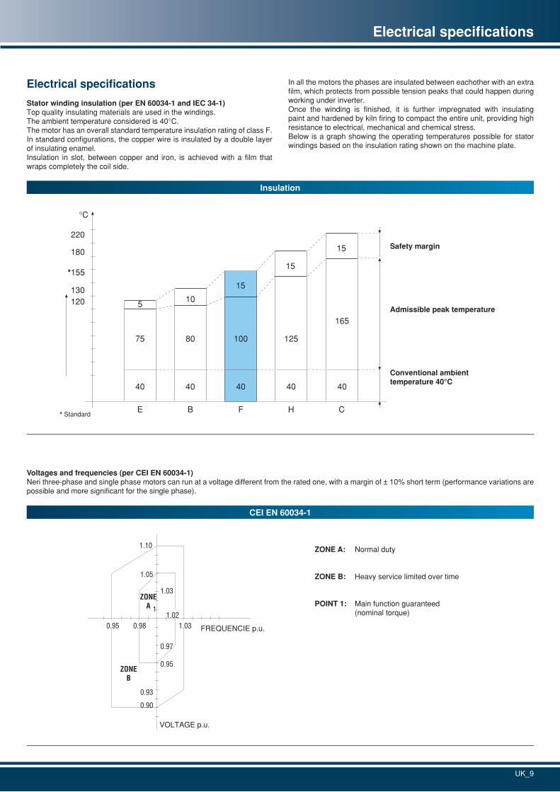
Stator winding insulation (per EN 60034-1 and IEC 34-1)Top quality insulating materials are used in the windings.The ambient temperature considered is 40°C.The motor has an overall standard temperature insulation rating of class F. In standard configurations, the copper wire is insulated by a double layer of insulating enamel. Insulation in slot, between copper and iron, is achieved with a film that wraps completely the coil side.
In all the motors the phases are insulated between eachother with an extra film, which protects from possible tension peaks that could happen during working under inverter.Once the winding is finished, it is further impregnated with insulating paint and hardened by kiln firing to compact the entire unit, providing high resistance to electrical, mechanical and chemical stress.Below is a graph showing the operating temperatures possible for stator windings based on the insulation rating shown on the machine plate.
Voltages and frequencies (per CEI EN 60034-1)Neri three-phase and single phase motors can run at a voltage different from the rated one, with a margin of ± 10% short term (performance variations are possible and more significant for the single phase).
CEI EN 60034-1
ZONE A: Normal duty
ZONE B: Heavy service limited over time
POINT 1: Main function guaranteed (nominal torque)
0.90
0.93
0.95
0.97
1
1.03
1.05
1.10
0.95 0.98 1.031.02
ZONE A
ZONEB
FREQUENCIE p.u.
VOLTAGE p.u.
UK_10
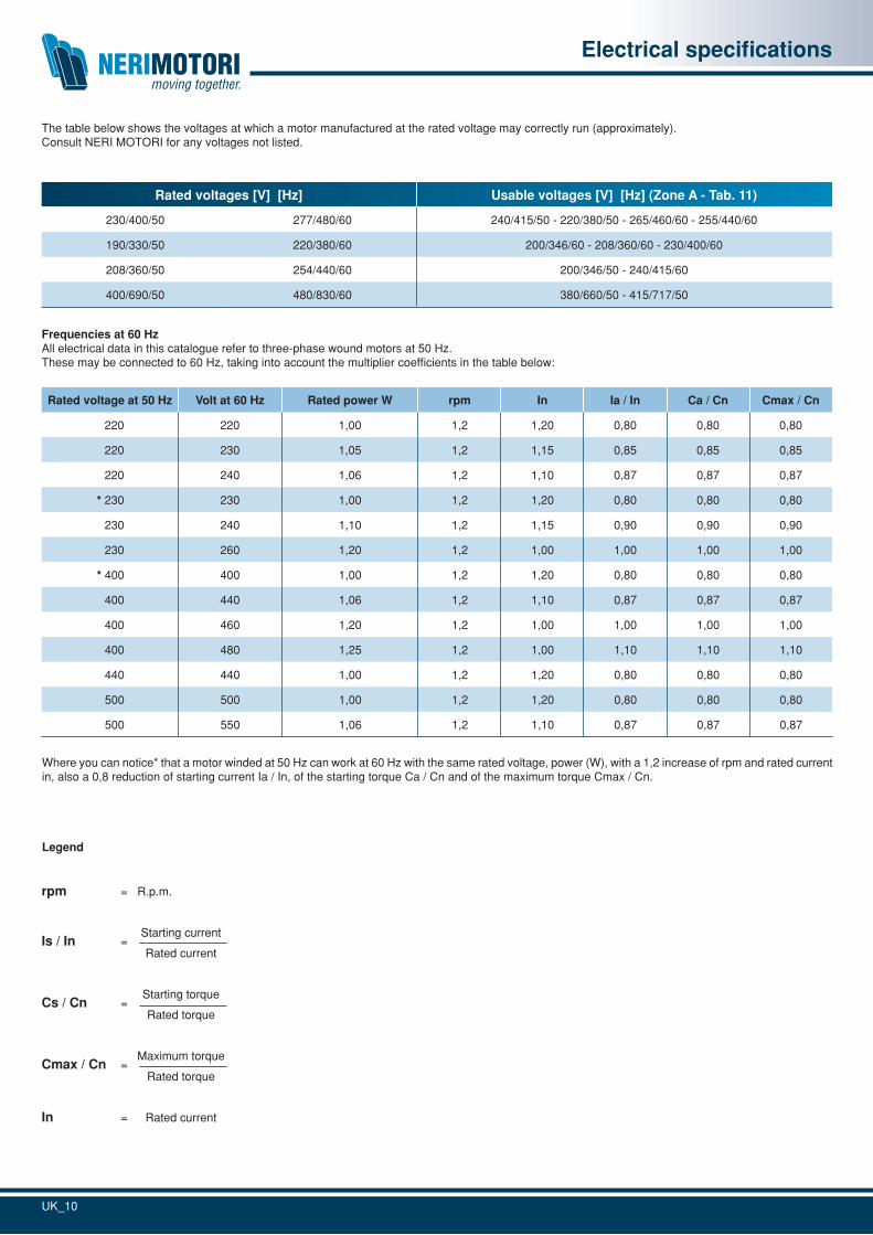
The table below shows the voltages at which a motor manufactured at the rated voltage may correctly run (approximately).Consult NERI MOTORI for any voltages not listed.
Rated voltages [V] [Hz] Usable voltages [V] [Hz] (Zone A - Tab. 11)
230/400/50 277/480/60 240/415/50 - 220/380/50 - 265/460/60 - 255/440/60
190/330/50 220/380/60 200/346/60 - 208/360/60 - 230/400/60
208/360/50 254/440/60 200/346/50 - 240/415/60
400/690/50 480/830/60 380/660/50 - 415/717/50
Electrical specifications
Frequencies at 60 HzAll electrical data in this catalogue refer to three-phase wound motors at 50 Hz.These may be connected to 60 Hz, taking into account the multiplier coefficients in the table below:
Rated voltage at 50 Hz Volt at 60 Hz Rated power W rpm In Ia / In Ca / Cn Cmax / Cn
220 220 1,00 1,2 1,20 0,80 0,80 0,80
220 230 1,05 1,2 1,15 0,85 0,85 0,85
220 240 1,06 1,2 1,10 0,87 0,87 0,87
* 230 230 1,00 1,2 1,20 0,80 0,80 0,80
230 240 1,10 1,2 1,15 0,90 0,90 0,90
230 260 1,20 1,2 1,00 1,00 1,00 1,00
* 400 400 1,00 1,2 1,20 0,80 0,80 0,80
400 440 1,06 1,2 1,10 0,87 0,87 0,87
400 460 1,20 1,2 1,00 1,00 1,00 1,00
400 480 1,25 1,2 1,00 1,10 1,10 1,10
440 440 1,00 1,2 1,20 0,80 0,80 0,80
500 500 1,00 1,2 1,20 0,80 0,80 0,80
500 550 1,06 1,2 1,10 0,87 0,87 0,87
Where you can notice* that a motor winded at 50 Hz can work at 60 Hz with the same rated voltage, power (W), with a 1,2 increase of rpm and rated current in, also a 0,8 reduction of starting current Ia / In, of the starting torque Ca / Cn and of the maximum torque Cmax / Cn.
Legend
rpm = R.p.m.
Is / In = Starting current
Rated current
Cs / Cn = Starting torque
Rated torque
Cmax / Cn = Maximum torque
Rated torque
In = Rated current
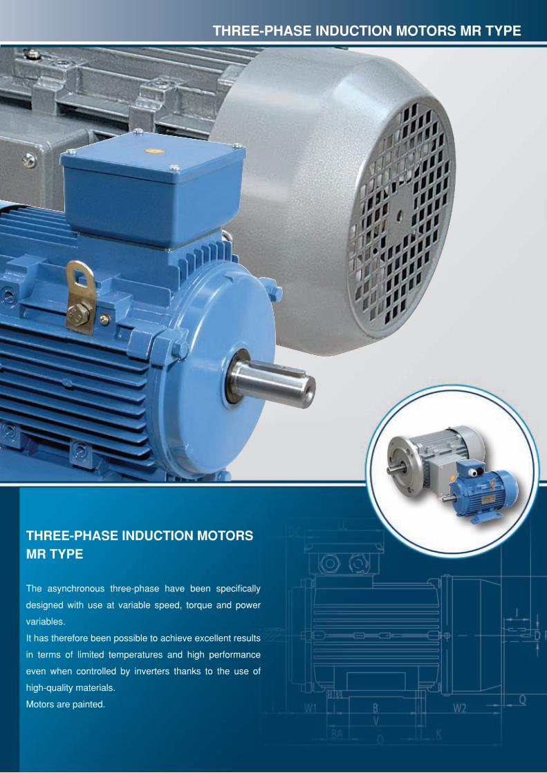
THREE-PHASE INDUCTION MOTORSMR TyPE
The asynchronous three-phase have been specifically
designed with use at variable speed, torque and power
variables.
It has therefore been possible to achieve excellent results
in terms of limited temperatures and high performance
even when controlled by inverters thanks to the use of
high-quality materials.
Motors are painted.
THREE-PHASE INDUCTION MOTORS MR TyPE
UK_12
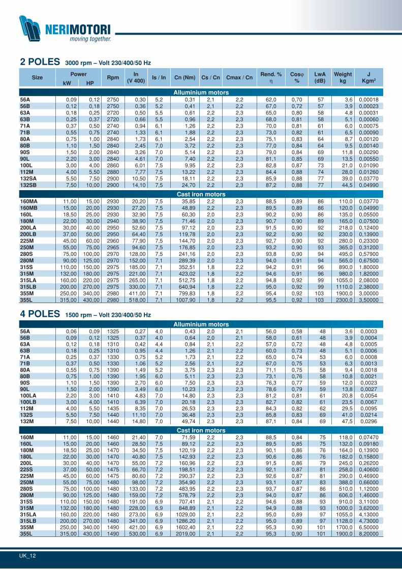
2 POLES 3000 rpm – Volt 230/400/50 Hz
SizePower
RpmIn
(V 400)Is / In Cn (Nm) Cs / Cn Cmax / Cn
Rend. %h
Cosj%
LwA(dB)
Weightkg
J Kgm2
kW HP
Alluminium motors56A 0,09 0,12 2750 0,30 5,2 0,31 2,1 2,2 62,0 0,70 57 3,6 0,0001856B 0,12 0,18 2750 0,36 5,2 0,41 2,1 2,2 67,0 0,72 57 3,9 0,0002363A 0,18 0,25 2720 0,50 5,5 0,61 2,2 2,3 65,0 0,80 58 4,8 0,0003163B 0,25 0,37 2720 0,66 5,5 0,96 2,2 2,3 68,0 0,81 58 5,1 0,0006071A 0,37 0,50 2740 0,94 6,1 1,26 2,2 2,3 70,0 0,81 61 6,0 0,0007571B 0,55 0,75 2740 1,33 6,1 1,88 2,2 2,3 73,0 0,82 61 6,5 0,0009080A 0,75 1,00 2840 1,73 6,1 2,54 2,2 2,3 75,1 0,83 64 8,7 0,0012080B 1,10 1,50 2840 2,45 7,0 3,72 2,2 2,3 77,0 0,84 64 9,5 0,0014090S 1,50 2,00 2840 3,26 7,0 5,14 2,2 2,3 79,0 0,84 69 11,8 0,0029090L 2,20 3,00 2840 4,61 7,0 7,40 2,2 2,3 81,1 0,85 69 13,5 0,00550100L 3,00 4,00 2860 6,01 7,5 9,95 2,2 2,3 82,8 0,87 73 21,0 0,01090112M 4,00 5,50 2880 7,77 7,5 13,22 2,2 2,3 84,4 0,88 74 28,0 0,01260132SA 5,50 7,50 2900 10,50 7,5 18,11 2,2 2,3 85,9 0,88 77 39,0 0,03770132SB 7,50 10,00 2900 14,10 7,5 24,70 2,2 2,3 87,2 0,88 77 44,5 0,04990
Cast iron motors160MA 11,00 15,00 2930 20,20 7,5 35,85 2,2 2,3 88,5 0,89 86 110,0 0,03770160MB 15,00 20,00 2930 27,20 7,5 48,89 2,2 2,3 89,5 0,89 86 120,0 0,04990160L 18,50 25,00 2930 32,90 7,5 60,30 2,0 2,3 90,2 0,90 86 135,0 0,05500180M 22,00 30,00 2940 38,90 7,5 71,46 2,0 2,3 90,7 0,90 89 165,0 0,07500200LA 30,00 40,00 2950 52,60 7,5 97,12 2,0 2,3 91,5 0,90 92 218,0 0,12400200LB 37,00 50,00 2950 64,40 7,5 119,78 2,0 2,3 92,2 0,90 92 230,0 0,13900225M 45,00 60,00 2960 77,90 7,5 144,70 2,0 2,3 92,7 0,90 92 280,0 0,23300250M 55,00 75,00 2965 94,60 7,5 176,85 2,0 2,3 93,2 0,90 93 365,0 0,31200280S 75,00 100,00 2970 128,00 7,5 241,16 2,0 2,3 93,8 0,90 94 495,0 0,57900280M 90,00 125,00 2970 152,00 7,1 289,39 2,0 2,3 94,0 0,91 94 565,0 0,67500315S 110,00 150,00 2975 185,00 7,1 352,51 1,8 2,2 94,2 0,91 96 890,0 1,80000315M 132,00 180,00 2975 221,00 7,1 423,02 1,8 2,2 94,6 0,91 96 980,0 1,82000315LA 160,00 220,00 2975 265,00 7,1 512,75 1,8 2,2 94,8 0,92 99 1055,0 2,08000315LB 200,00 270,00 2975 330,00 7,1 640,94 1,8 2,2 95,0 0,92 99 1110,0 2,38000355M 250,00 340,00 2980 411,00 7,1 799,83 1,8 2,2 95,4 0,92 103 1900,0 3,00000355L 315,00 430,00 2980 518,00 7,1 1007,90 1,8 2,2 95,5 0,92 103 2300,0 3,50000
4 POLES 1500 rpm – Volt 230/400/50 Hz
Alluminium motors56A 0,06 0,09 1325 0,27 4,0 0,43 2,0 2,1 56,0 0,58 48 3,6 0,000356B 0,09 0,12 1325 0,37 4,0 0,64 2,0 2,1 58,0 0,61 48 3,9 0,000463A 0,12 0,18 1310 0,42 4,4 0,84 2,1 2,2 57,0 0,72 48 4,8 0,000563B 0,18 0,25 1310 0,95 4,4 1,26 2,1 2,2 60,0 0,73 48 5,1 0,000671A 0,25 0,37 1330 0,75 5,2 1,73 2,1 2,2 65,0 0,74 53 6,0 0,000871B 0,37 0,50 1330 1,06 5,2 2,56 2,1 2,2 67,0 0,75 53 6,3 0,001380A 0,55 0,75 1390 1,49 5,2 3,75 2,3 2,3 71,1 0,75 58 9,4 0,001880B 0,75 1,00 1390 1,95 6,0 5,11 2,3 2,3 73,1 0,76 58 10,8 0,002190S 1,10 1,50 1390 2,70 6,0 7,50 2,3 2,3 76,3 0,77 59 12,0 0,002390L 1,50 2,00 1390 3,49 6,0 10,23 2,3 2,3 78,6 0,79 59 13,8 0,0027100LA 2,20 3,00 1410 4,83 7,0 14,80 2,3 2,3 81,2 0,81 61 20,8 0,0054100LB 3,00 4,00 1410 6,39 7,0 20,18 2,3 2,3 82,7 0,82 61 23,5 0,0067112M 4,00 5,50 1435 8,35 7,0 26,53 2,3 2,3 84,3 0,82 62 29,5 0,0095132S 5,50 7,50 1440 11,10 7,0 36,48 2,3 2,3 85,8 0,83 69 41,0 0,0214132M 7,50 10,00 1440 14,80 7,0 49,74 2,3 2,3 87,1 0,84 69 47,5 0,0296
Cast iron motors160M 11,00 15,00 1460 21,40 7,0 71,59 2,2 2,3 88,5 0,84 75 118,0 0,07470160L 15,00 20,00 1460 28,50 7,5 89,12 2,2 2,3 89,5 0,85 75 132,0 0,09180180M 18,50 25,00 1470 34,50 7,5 120,19 2,2 2,3 90,1 0,86 76 164,0 0,13900180L 22,00 30,00 1470 40,80 7,5 142,93 2,2 2,3 90,6 0,86 76 182,0 0,15800200L 30,00 40,00 1470 55,00 7,2 160,96 2,2 2,3 91,5 0,86 79 245,0 0,26200225S 37,00 50,00 1475 66,70 7,2 198,51 2,2 2,3 92,1 0,87 81 258,0 0,40600225M 45,00 60,00 1475 80,60 7,2 290,37 2,2 2,3 92,6 0,87 81 290,0 0,46900250M 55,00 75,00 1480 98,00 7,2 354,90 2,2 2,3 93,1 0,87 83 388,0 0,66000280S 75,00 100,00 1480 133,00 7,2 483,95 2,2 2,3 93,7 0,87 86 510,0 1,12000280M 90,00 125,00 1480 159,00 7,2 578,79 2,2 2,3 94,0 0,87 86 606,0 1,46000315S 110,00 150,00 1480 191,00 6,9 707,41 2,1 2,2 94,6 0,88 93 910,0 3,11000315M 132,00 180,00 1480 228,00 6,9 848,89 2,1 2,2 94,9 0,88 93 1000,0 3,62000315LA 160,00 220,00 1480 273,00 6,9 1029,00 2,1 2,2 95,0 0,89 97 1055,0 4,13000315LB 200,00 270,00 1480 341,00 6,9 1286,20 2,1 2,2 95,0 0,89 97 1128,0 4,73000355M 250,00 340,00 1490 421,00 6,9 1602,40 2,1 2,2 95,3 0,90 101 1700,0 6,50000355L 315,00 430,00 1490 530,00 6,9 2019,00 2,1 2,2 95,3 0,90 101 1900,0 8,20000
UK_13
MR type
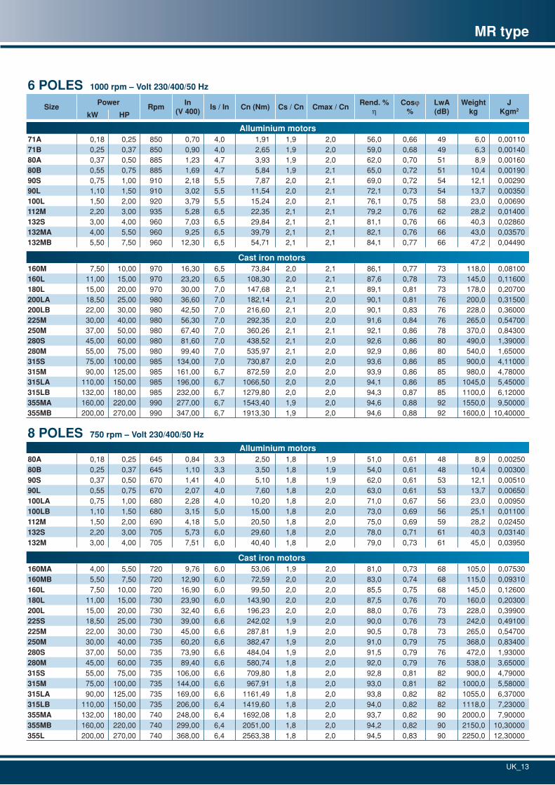
6 POLES 1000 rpm – Volt 230/400/50 Hz
SizePower
RpmIn
(V 400)Is / In Cn (Nm) Cs / Cn Cmax / Cn
Rend. %h
Cosj%
LwA(dB)
Weightkg
J Kgm2
kW HP
Alluminium motors71A 0,18 0,25 850 0,70 4,0 1,91 1,9 2,0 56,0 0,66 49 6,0 0,0011071B 0,25 0,37 850 0,90 4,0 2,65 1,9 2,0 59,0 0,68 49 6,3 0,0014080A 0,37 0,50 885 1,23 4,7 3,93 1,9 2,0 62,0 0,70 51 8,9 0,0016080B 0,55 0,75 885 1,69 4,7 5,84 1,9 2,1 65,0 0,72 51 10,4 0,0019090S 0,75 1,00 910 2,18 5,5 7,87 2,0 2,1 69,0 0,72 54 12,1 0,0029090L 1,10 1,50 910 3,02 5,5 11,54 2,0 2,1 72,1 0,73 54 13,7 0,00350100L 1,50 2,00 920 3,79 5,5 15,24 2,0 2,1 76,1 0,75 58 23,0 0,00690112M 2,20 3,00 935 5,28 6,5 22,35 2,1 2,1 79,2 0,76 62 28,2 0,01400132S 3,00 4,00 960 7,03 6,5 29,84 2,1 2,1 81,1 0,76 66 40,3 0,02860132MA 4,00 5,50 960 9,25 6,5 39,79 2,1 2,1 82,1 0,76 66 43,0 0,03570132MB 5,50 7,50 960 12,30 6,5 54,71 2,1 2,1 84,1 0,77 66 47,2 0,04490
Cast iron motors160M 7,50 10,00 970 16,30 6,5 73,84 2,0 2,1 86,1 0,77 73 118,0 0,08100160L 11,00 15,00 970 23,20 6,5 108,30 2,0 2,1 87,6 0,78 73 145,0 0,11600180L 15,00 20,00 970 30,00 7,0 147,68 2,1 2,1 89,1 0,81 73 178,0 0,20700200LA 18,50 25,00 980 36,60 7,0 182,14 2,1 2,0 90,1 0,81 76 200,0 0,31500200LB 22,00 30,00 980 42,50 7,0 216,60 2,1 2,0 90,1 0,83 76 228,0 0,36000225M 30,00 40,00 980 56,30 7,0 292,35 2,0 2,0 91,6 0,84 76 265,0 0,54700250M 37,00 50,00 980 67,40 7,0 360,26 2,1 2,1 92,1 0,86 78 370,0 0,84300280S 45,00 60,00 980 81,60 7,0 438,52 2,1 2,0 92,6 0,86 80 490,0 1,39000280M 55,00 75,00 980 99,40 7,0 535,97 2,1 2,0 92,9 0,86 80 540,0 1,65000315S 75,00 100,00 985 134,00 7,0 730,87 2,0 2,0 93,6 0,86 85 900,0 4,11000315M 90,00 125,00 985 161,00 6,7 872,59 2,0 2,0 93,9 0,86 85 980,0 4,78000315LA 110,00 150,00 985 196,00 6,7 1066,50 2,0 2,0 94,1 0,86 85 1045,0 5,45000315LB 132,00 180,00 985 232,00 6,7 1279,80 2,0 2,0 94,3 0,87 85 1100,0 6,12000355MA 160,00 220,00 990 277,00 6,7 1543,40 1,9 2,0 94,6 0,88 92 1550,0 9,50000355MB 200,00 270,00 990 347,00 6,7 1913,30 1,9 2,0 94,6 0,88 92 1600,0 10,40000
8 POLES 750 rpm – Volt 230/400/50 Hz
Alluminium motors80A 0,18 0,25 645 0,84 3,3 2,50 1,8 1,9 51,0 0,61 48 8,9 0,0025080B 0,25 0,37 645 1,10 3,3 3,50 1,8 1,9 54,0 0,61 48 10,4 0,0030090S 0,37 0,50 670 1,41 4,0 5,10 1,8 1,9 62,0 0,61 53 12,1 0,0051090L 0,55 0,75 670 2,07 4,0 7,60 1,8 2,0 63,0 0,61 53 13,7 0,00650100LA 0,75 1,00 680 2,28 4,0 10,20 1,8 2,0 71,0 0,67 56 23,0 0,00950100LB 1,10 1,50 680 3,15 5,0 15,00 1,8 2,0 73,0 0,69 56 25,1 0,01100112M 1,50 2,00 690 4,18 5,0 20,50 1,8 2,0 75,0 0,69 59 28,2 0,02450132S 2,20 3,00 705 5,73 6,0 29,60 1,8 2,0 78,0 0,71 61 40,3 0,03140132M 3,00 4,00 705 7,51 6,0 40,40 1,8 2,0 79,0 0,73 61 45,0 0,03950
Cast iron motors160MA 4,00 5,50 720 9,76 6,0 53,06 1,9 2,0 81,0 0,73 68 105,0 0,07530160MB 5,50 7,50 720 12,90 6,0 72,59 2,0 2,0 83,0 0,74 68 115,0 0,09310160L 7,50 10,00 720 16,90 6,0 99,50 2,0 2,0 85,5 0,75 68 145,0 0,12600180L 11,00 15,00 730 23,90 6,0 143,90 2,0 2,0 87,5 0,76 70 160,0 0,20300200L 15,00 20,00 730 32,40 6,6 196,23 2,0 2,0 88,0 0,76 73 228,0 0,39900225S 18,50 25,00 730 39,00 6,6 242,02 1,9 2,0 90,0 0,76 73 242,0 0,49100225M 22,00 30,00 730 45,00 6,6 287,81 1,9 2,0 90,5 0,78 73 265,0 0,54700250M 30,00 40,00 735 60,20 6,6 382,47 1,9 2,0 91,0 0,79 75 368,0 0,83400280S 37,00 50,00 735 73,90 6,6 484,04 1,9 2,0 91,5 0,79 76 472,0 1,93000280M 45,00 60,00 735 89,40 6,6 580,74 1,8 2,0 92,0 0,79 76 538,0 3,65000315S 55,00 75,00 735 106,00 6,6 709,80 1,8 2,0 92,8 0,81 82 900,0 4,79000315M 75,00 100,00 735 144,00 6,6 967,91 1,8 2,0 93,0 0,81 82 1000,0 5,58000315LA 90,00 125,00 735 169,00 6,6 1161,49 1,8 2,0 93,8 0,82 82 1055,0 6,37000315LB 110,00 150,00 735 206,00 6,4 1419,60 1,8 2,0 94,0 0,82 82 1118,0 7,23000355MA 132,00 180,00 740 248,00 6,4 1692,08 1,8 2,0 93,7 0,82 90 2000,0 7,90000355MB 160,00 220,00 740 299,00 6,4 2051,00 1,8 2,0 94,2 0,82 90 2150,0 10,30000355L 200,00 270,00 740 368,00 6,4 2563,38 1,8 2,0 94,5 0,83 90 2250,0 12,30000
UK_14
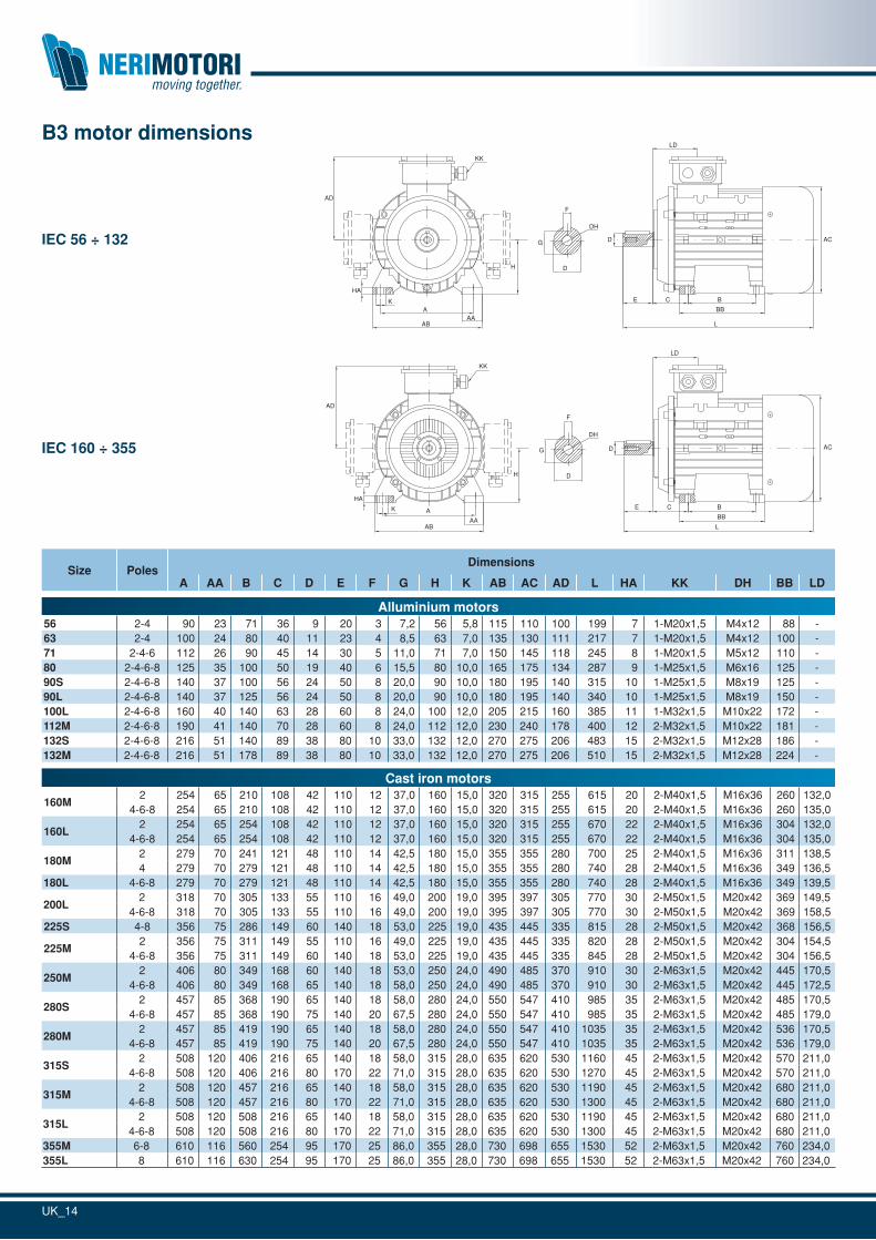
Size PolesDimensions
A AA B C D E F G H K AB AC AD L HA KK DH BB LD
Alluminium motors56 2-4 90 23 71 36 9 20 3 7,2 56 5,8 115 110 100 199 7 1-M20x1,5 M4x12 88 -63 2-4 100 24 80 40 11 23 4 8,5 63 7,0 135 130 111 217 7 1-M20x1,5 M4x12 100 -71 2-4-6 112 26 90 45 14 30 5 11,0 71 7,0 150 145 118 245 8 1-M20x1,5 M5x12 110 -80 2-4-6-8 125 35 100 50 19 40 6 15,5 80 10,0 165 175 134 287 9 1-M25x1,5 M6x16 125 -90S 2-4-6-8 140 37 100 56 24 50 8 20,0 90 10,0 180 195 140 315 10 1-M25x1,5 M8x19 125 -90L 2-4-6-8 140 37 125 56 24 50 8 20,0 90 10,0 180 195 140 340 10 1-M25x1,5 M8x19 150 -100L 2-4-6-8 160 40 140 63 28 60 8 24,0 100 12,0 205 215 160 385 11 1-M32x1,5 M10x22 172 -112M 2-4-6-8 190 41 140 70 28 60 8 24,0 112 12,0 230 240 178 400 12 2-M32x1,5 M10x22 181 -132S 2-4-6-8 216 51 140 89 38 80 10 33,0 132 12,0 270 275 206 483 15 2-M32x1,5 M12x28 186 -132M 2-4-6-8 216 51 178 89 38 80 10 33,0 132 12,0 270 275 206 510 15 2-M32x1,5 M12x28 224 -
Cast iron motors
160M2 254 65 210 108 42 110 12 37,0 160 15,0 320 315 255 615 20 2-M40x1,5 M16x36 260 132,0
4-6-8 254 65 210 108 42 110 12 37,0 160 15,0 320 315 255 615 20 2-M40x1,5 M16x36 260 135,0
160L2 254 65 254 108 42 110 12 37,0 160 15,0 320 315 255 670 22 2-M40x1,5 M16x36 304 132,0
4-6-8 254 65 254 108 42 110 12 37,0 160 15,0 320 315 255 670 22 2-M40x1,5 M16x36 304 135,0
180M2 279 70 241 121 48 110 14 42,5 180 15,0 355 355 280 700 25 2-M40x1,5 M16x36 311 138,54 279 70 279 121 48 110 14 42,5 180 15,0 355 355 280 740 28 2-M40x1,5 M16x36 349 136,5
180L 4-6-8 279 70 279 121 48 110 14 42,5 180 15,0 355 355 280 740 28 2-M40x1,5 M16x36 349 139,5
200L2 318 70 305 133 55 110 16 49,0 200 19,0 395 397 305 770 30 2-M50x1,5 M20x42 369 149,5
4-6-8 318 70 305 133 55 110 16 49,0 200 19,0 395 397 305 770 30 2-M50x1,5 M20x42 369 158,5225S 4-8 356 75 286 149 60 140 18 53,0 225 19,0 435 445 335 815 28 2-M50x1,5 M20x42 368 156,5
225M2 356 75 311 149 55 110 16 49,0 225 19,0 435 445 335 820 28 2-M50x1,5 M20x42 304 154,5
4-6-8 356 75 311 149 60 140 18 53,0 225 19,0 435 445 335 845 28 2-M50x1,5 M20x42 304 156,5
250M2 406 80 349 168 60 140 18 53,0 250 24,0 490 485 370 910 30 2-M63x1,5 M20x42 445 170,5
4-6-8 406 80 349 168 65 140 18 58,0 250 24,0 490 485 370 910 30 2-M63x1,5 M20x42 445 172,5
280S2 457 85 368 190 65 140 18 58,0 280 24,0 550 547 410 985 35 2-M63x1,5 M20x42 485 170,5
4-6-8 457 85 368 190 75 140 20 67,5 280 24,0 550 547 410 985 35 2-M63x1,5 M20x42 485 179,0
280M2 457 85 419 190 65 140 18 58,0 280 24,0 550 547 410 1035 35 2-M63x1,5 M20x42 536 170,5
4-6-8 457 85 419 190 75 140 20 67,5 280 24,0 550 547 410 1035 35 2-M63x1,5 M20x42 536 179,0
315S2 508 120 406 216 65 140 18 58,0 315 28,0 635 620 530 1160 45 2-M63x1,5 M20x42 570 211,0
4-6-8 508 120 406 216 80 170 22 71,0 315 28,0 635 620 530 1270 45 2-M63x1,5 M20x42 570 211,0
315M2 508 120 457 216 65 140 18 58,0 315 28,0 635 620 530 1190 45 2-M63x1,5 M20x42 680 211,0
4-6-8 508 120 457 216 80 170 22 71,0 315 28,0 635 620 530 1300 45 2-M63x1,5 M20x42 680 211,0
315L2 508 120 508 216 65 140 18 58,0 315 28,0 635 620 530 1190 45 2-M63x1,5 M20x42 680 211,0
4-6-8 508 120 508 216 80 170 22 71,0 315 28,0 635 620 530 1300 45 2-M63x1,5 M20x42 680 211,0355M 6-8 610 116 560 254 95 170 25 86,0 355 28,0 730 698 655 1530 52 2-M63x1,5 M20x42 760 234,0355L 8 610 116 630 254 95 170 25 86,0 355 28,0 730 698 655 1530 52 2-M63x1,5 M20x42 760 234,0
B3 motor dimensions
DH
D
F
G
E C B
BB
L
LD
D AC
KK
A
AB
AD
H
K
HA
AA
DH
D
F
G
E C B
BB
L
LD
D AC
KK
A
AB
AD
H
K
HA
AA
IEC 56 ÷ 132
IEC 160 ÷ 355
UK_15
SizeDimensions Overall size
HA AC AD B C D DH E F G H K KK L M N P S T
Alluminium motors56 7 110 100 71 36 9 M4x12 20 3 7,2 56 5,8 1-M20x1,5 199 100 80 120 7 3,063 7 130 111 80 40 11 M4x12 23 4 8,5 63 7,0 1-M20x1,5 217 115 95 140 10 3,071 8 145 118 90 45 14 M5x12 30 5 11,0 71 7,0 1-M20x1,5 245 130 110 160 12 3,580 9 175 134 100 50 19 M6x16 40 6 15,5 80 7,0 1-M25x1,5 287 165 130 200 12 3,590S 10 195 140 100 56 24 M8x19 50 8 20,0 90 10,0 1-M25x1,5 315 165 130 200 12 3,590L 10 195 140 125 56 24 M8x19 50 8 20,0 90 10,0 1-M25x1,5 340 165 130 200 12 4,0100L 11 215 160 140 63 28 M10x22 50 8 24,0 100 12,0 1-M32x1,5 385 215 180 250 15 4,0112M 12 240 178 140 70 28 M10x22 60 8 24,0 112 12,0 2-M32x1,5 400 215 180 250 15 4,0132S 15 275 206 140 89 38 M12x28 80 10 33,0 132 12,0 2-M32x1,5 483 265 230 300 15 4,0132M 15 275 206 178 89 38 M12x28 80 10 33,0 132 12,0 2-M32x1,5 510 265 230 300 15 4,0
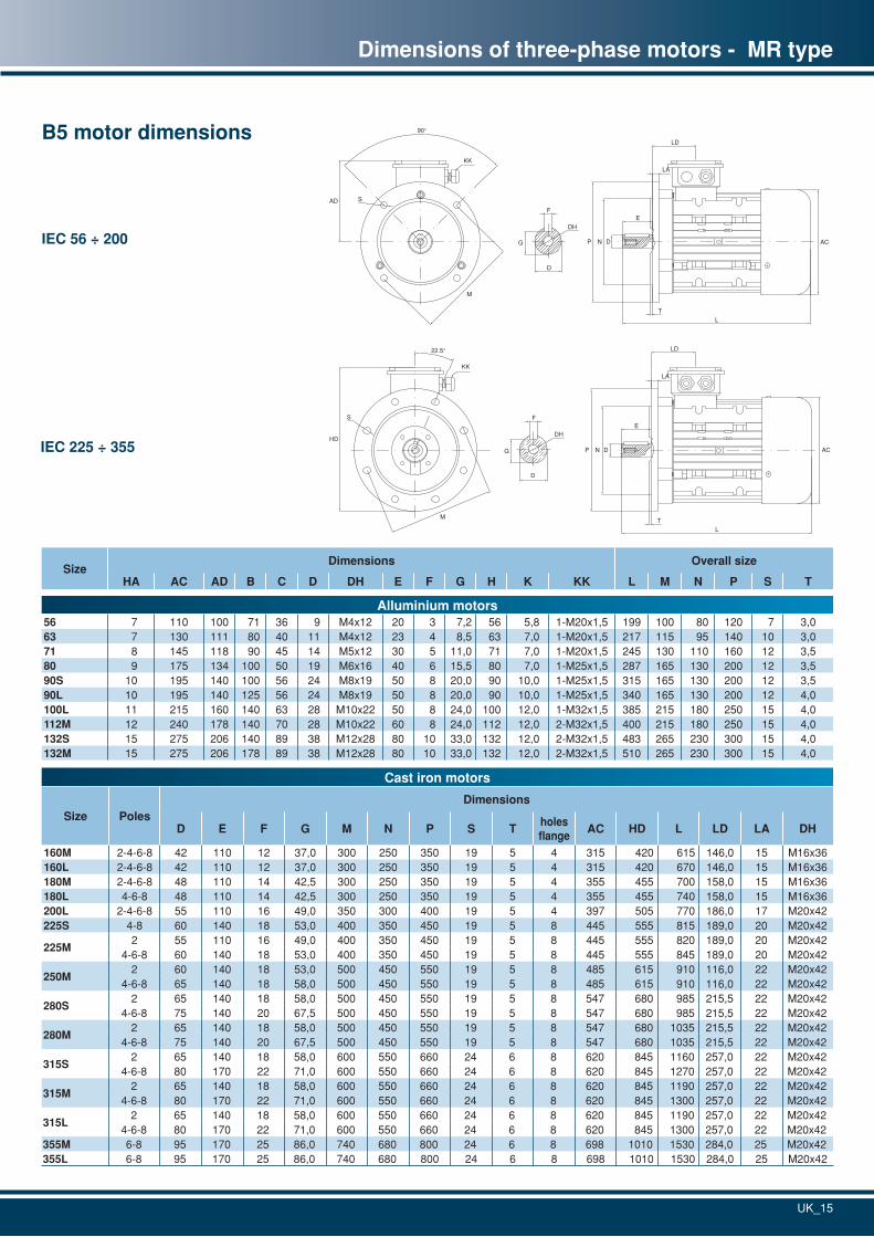
Dimensions of three-phase motors - MR type
B5 motor dimensions
IEC 56 ÷ 200
IEC 225 ÷ 355DH
D
F
G
E
L
LD
ACP N D
LA
T
KK
HD
M
22.5°
S
DH
D
F
G
KK
90°
SAD
M
E
L
LD
ACP N D
LA
T
Cast iron motors
Size PolesDimensions
D E F G M N P S Tholesflange
AC HD L LD LA DH
160M 2-4-6-8 42 110 12 37,0 300 250 350 19 5 4 315 420 615 146,0 15 M16x36160L 2-4-6-8 42 110 12 37,0 300 250 350 19 5 4 315 420 670 146,0 15 M16x36180M 2-4-6-8 48 110 14 42,5 300 250 350 19 5 4 355 455 700 158,0 15 M16x36180L 4-6-8 48 110 14 42,5 300 250 350 19 5 4 355 455 740 158,0 15 M16x36200L 2-4-6-8 55 110 16 49,0 350 300 400 19 5 4 397 505 770 186,0 17 M20x42225S 4-8 60 140 18 53,0 400 350 450 19 5 8 445 555 815 189,0 20 M20x42
225M2 55 110 16 49,0 400 350 450 19 5 8 445 555 820 189,0 20 M20x42
4-6-8 60 140 18 53,0 400 350 450 19 5 8 445 555 845 189,0 20 M20x42
250M2 60 140 18 53,0 500 450 550 19 5 8 485 615 910 116,0 22 M20x42
4-6-8 65 140 18 58,0 500 450 550 19 5 8 485 615 910 116,0 22 M20x42
280S2 65 140 18 58,0 500 450 550 19 5 8 547 680 985 215,5 22 M20x42
4-6-8 75 140 20 67,5 500 450 550 19 5 8 547 680 985 215,5 22 M20x42
280M2 65 140 18 58,0 500 450 550 19 5 8 547 680 1035 215,5 22 M20x42
4-6-8 75 140 20 67,5 500 450 550 19 5 8 547 680 1035 215,5 22 M20x42
315S2 65 140 18 58,0 600 550 660 24 6 8 620 845 1160 257,0 22 M20x42
4-6-8 80 170 22 71,0 600 550 660 24 6 8 620 845 1270 257,0 22 M20x42
315M2 65 140 18 58,0 600 550 660 24 6 8 620 845 1190 257,0 22 M20x42
4-6-8 80 170 22 71,0 600 550 660 24 6 8 620 845 1300 257,0 22 M20x42
315L2 65 140 18 58,0 600 550 660 24 6 8 620 845 1190 257,0 22 M20x42
4-6-8 80 170 22 71,0 600 550 660 24 6 8 620 845 1300 257,0 22 M20x42355M 6-8 95 170 25 86,0 740 680 800 24 6 8 698 1010 1530 284,0 25 M20x42355L 6-8 95 170 25 86,0 740 680 800 24 6 8 698 1010 1530 284,0 25 M20x42
UK_16
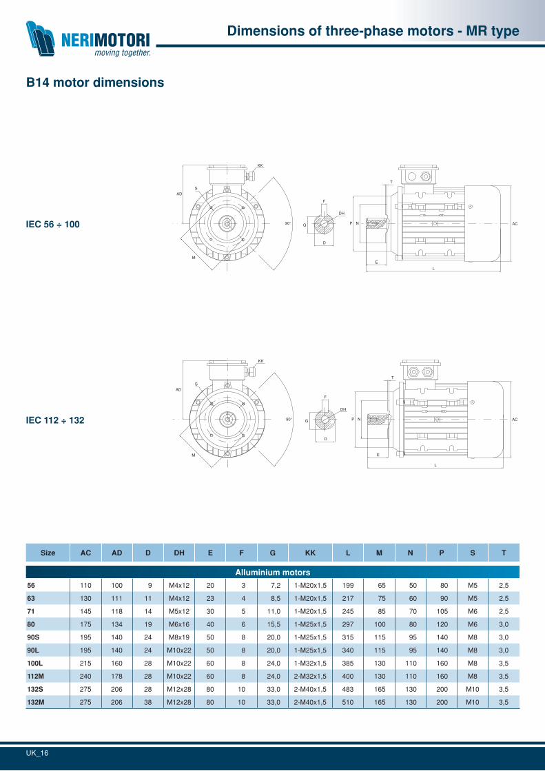
Size AC AD D DH E F G KK L M N P S T
Alluminium motors
56 110 100 9 M4x12 20 3 7,2 1-M20x1,5 199 65 50 80 M5 2,5
63 130 111 11 M4x12 23 4 8,5 1-M20x1,5 217 75 60 90 M5 2,5
71 145 118 14 M5x12 30 5 11,0 1-M20x1,5 245 85 70 105 M6 2,5
80 175 134 19 M6x16 40 6 15,5 1-M25x1,5 297 100 80 120 M6 3,0
90S 195 140 24 M8x19 50 8 20,0 1-M25x1,5 315 115 95 140 M8 3,0
90L 195 140 24 M10x22 50 8 20,0 1-M25x1,5 340 115 95 140 M8 3,0
100L 215 160 28 M10x22 60 8 24,0 1-M32x1,5 385 130 110 160 M8 3,5
112M 240 178 28 M10x22 60 8 24,0 2-M32x1,5 400 130 110 160 M8 3,5
132S 275 206 28 M12x28 80 10 33,0 2-M40x1,5 483 165 130 200 M10 3,5
132M 275 206 38 M12x28 80 10 33,0 2-M40x1,5 510 165 130 200 M10 3,5
Dimensions of three-phase motors - MR type
B14 motor dimensions
KK
L
E
T
DH
D
F
G90°
ADS
NP AC
M
IEC 56 ÷ 100
KK
L
E
T
DH
D
F
G90°
ADS
NP AC
M
IEC 112 ÷ 132
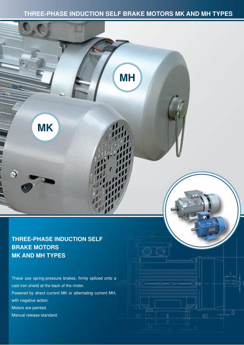
MK
MH
THREE-PHASE INDUCTION SELF BRAKE MOTORSMK AND MH TyPES
These use spring-pressure brakes, firmly spliced onto a
cast iron shield at the back of the motor.
Powered by direct current MK or alternating current MH,
with negative action.
Motors are painted.
Manual release standard.
THREE-PHASE INDUCTION SELF BRAKE MOTORS MK AND MH TyPES
UK_18
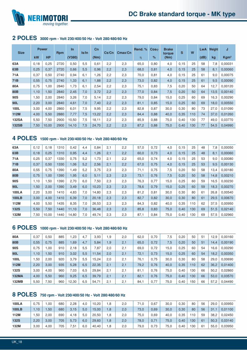
DC Brake standard torque - MK type
2 POLES 3000 rpm - Volt 230/400/50 Hz - Volt 280/480/60 Hz
SizePower
RpmIn
(V380)Is/In
Cn
(Nm)Cs/Cn Cmax/Cn
Rend. %
h
Cosj
%
Braketorque(Nm)
S WLwA
(dB)
Weight
kg
J
Kgm2kW HP
63A 0,18 0,25 2720 0,50 5,5 0,61 2,2 2,3 65,0 0,80 4,0 0,15 25 58 7,8 0,00031
63B 0,25 0,37 2720 0,66 5,5 0,96 2,2 2,3 68,0 0,81 4,0 0,15 25 58 8,1 0,00060
71A 0,37 0,50 2740 0,94 6,1 1,26 2,2 2,3 70,0 0,81 4,0 0,15 25 61 9,0 0,00075
71B 0,55 0,75 2740 1,33 6,1 1,88 2,2 2,3 73,0 0,82 4,0 0,15 25 61 9,5 0,00090
80A 0,75 1,00 2840 1,73 6,1 2,54 2,2 2,3 75,1 0,83 7,5 0,20 50 64 12,7 0,00120
80B 1,10 1,50 2840 2,45 7,0 3,72 2,2 2,3 77,0 0,84 7,5 0,20 50 64 13,5 0,00140
90S 1,50 2,00 2840 3,26 7,0 5,14 2,2 2,3 79,0 0,84 15,0 0,25 60 69 16,3 0,00290
90L 2,20 3,00 2840 4,61 7,0 7,40 2,2 2,3 81,1 0,85 15,0 0,25 60 69 18,0 0,00550
100L 3,00 4,00 2860 6,01 7,5 9,95 2,2 2,3 82,8 0,87 30,0 0,30 80 73 27,0 0,01090
112M 4,00 5,50 2880 7,77 7,5 13,22 2,2 2,3 84,4 0,88 40,0 0,35 110 74 37,0 0,01260
132SA 5,50 7,50 2900 10,50 7,5 18,11 2,2 2,3 85,9 0,88 75,0 0,40 130 77 49,0 0,03770
132SB 7,50 10,00 2900 14,10 7,5 24,70 2,2 2,3 87,2 0,88 75,0 0,40 130 77 54,5 0,04990
4 POLES 1500 rpm - Volt 230/400/50 Hz - Volt 280/480/60 Hz
63A 0,12 0,18 1310 0,42 4,4 0,84 2,1 2,2 57,0 0,72 4,0 0,15 25 48 7,8 0,00050
63B 0,18 0,25 1310 0,95 4,4 1,26 2,1 2,2 60,0 0,73 4,0 0,15 25 48 8,1 0,00060
71A 0,25 0,37 1330 0,75 5,2 1,73 2,1 2,2 65,0 0,74 4,0 0,15 25 53 9,0 0,00080
71B 0,37 0,50 1330 1,06 5,2 2,56 2,1 2,2 67,0 0,75 4,0 0,15 25 53 9,5 0,00130
80A 0,55 0,75 1390 1,49 5,2 3,75 2,3 2,3 71,1 0,75 7,5 0,20 50 58 13,4 0,00180
80B 0,75 1,00 1390 1,95 6,0 5,11 2,3 2,3 73,1 0,76 7,5 0,20 50 58 14,8 0,00210
90S 1,10 1,50 1390 2,70 6,0 7,50 2,3 2,3 76,3 0,77 15,0 0,25 60 59 16,5 0,00230
90L 1,50 2,00 1390 3,49 6,0 10,23 2,3 2,3 78,6 0,79 15,0 0,25 60 59 18,3 0,00270
100LA 2,20 3,00 1410 4,83 7,0 14,80 2,3 2,3 81,2 0,81 30,0 0,30 80 61 26,8 0,00540
100LB 3,00 4,00 1410 6,39 7,0 20,18 2,3 2,3 82,7 0,82 30,0 0,30 80 61 29,5 0,00670
112M 4,00 5,50 1435 8,35 7,0 26,53 2,3 2,3 84,3 0,82 40,0 0,35 110 62 37,5 0,00950
132S 5,50 7,50 1440 11,10 7,0 36,48 2,3 2,3 85,8 0,83 75,0 0,40 130 69 51,5 0,02140
132M 7,50 10,00 1440 14,80 7,0 49,74 2,3 2,3 87,1 0,84 75,0 0,40 130 69 57,5 0,02960
6 POLES 1000 rpm - Volt 230/400/50 Hz - Volt 280/480/60 Hz
80A 0,37 0,50 885 1,23 4,7 3,93 1,9 2,0 62,0 0,70 7,5 0,20 50 51 12,9 0,00160
80B 0,55 0,75 885 1,69 4,7 5,84 1,9 2,1 65,0 0,72 7,5 0,20 50 51 14,4 0,00190
90S 0,75 1,00 910 2,18 5,5 7,87 2,0 2,1 69,0 0,72 15,0 0,25 60 54 16,6 0,00290
90L 1,10 1,50 910 3,02 5,5 11,54 2,0 2,1 72,1 0,73 15,0 0,25 60 54 18,2 0,00350
100L 1,50 2,00 920 3,79 5,5 15,24 2,0 2,1 76,1 0,75 30,0 0,30 80 58 29,0 0,00690
112M 2,20 3,00 935 5,28 6,5 22,35 2,1 2,1 79,2 0,76 40,0 0,35 110 62 36,2 0,01400
132S 3,00 4,00 960 7,03 6,5 29,84 2,1 2,1 81,1 0,76 75,0 0,40 130 66 50,2 0,02860
132MA 4,00 5,50 960 9,25 6,5 39,79 2,1 2,1 82,1 0,76 75,0 0,40 130 66 53,0 0,03570
132MB 5,50 7,50 960 12,30 6,5 54,71 2,1 2,1 84,1 0,77 75,0 0,40 150 66 57,2 0,04490
8 POLES 750 rpm - Volt 230/400/50 Hz - Volt 280/480/60 Hz
100LA 0,75 1,00 680 2,28 4,0 10,20 1,8 2,0 71,0 0,67 30,0 0,30 80 56 29,0 0,00950
100LB 1,10 1,50 680 3,15 5,0 15,00 1,8 2,0 73,0 0,69 30,0 0,30 80 56 31,1 0,01100
112M 1,50 2,00 690 4,18 5,0 20,50 1,8 2,0 75,0 0,69 40,0 0,35 110 59 38,2 0,02450
132S 2,20 3,00 705 5,73 6,0 29,60 1,8 2,0 78,0 0,71 75,0 0,40 130 61 50,3 0,03140
132M 3,00 4,00 705 7,51 6,0 40,40 1,8 2,0 79,0 0,73 75,0 0,40 130 61 55,0 0,03950
UK_19
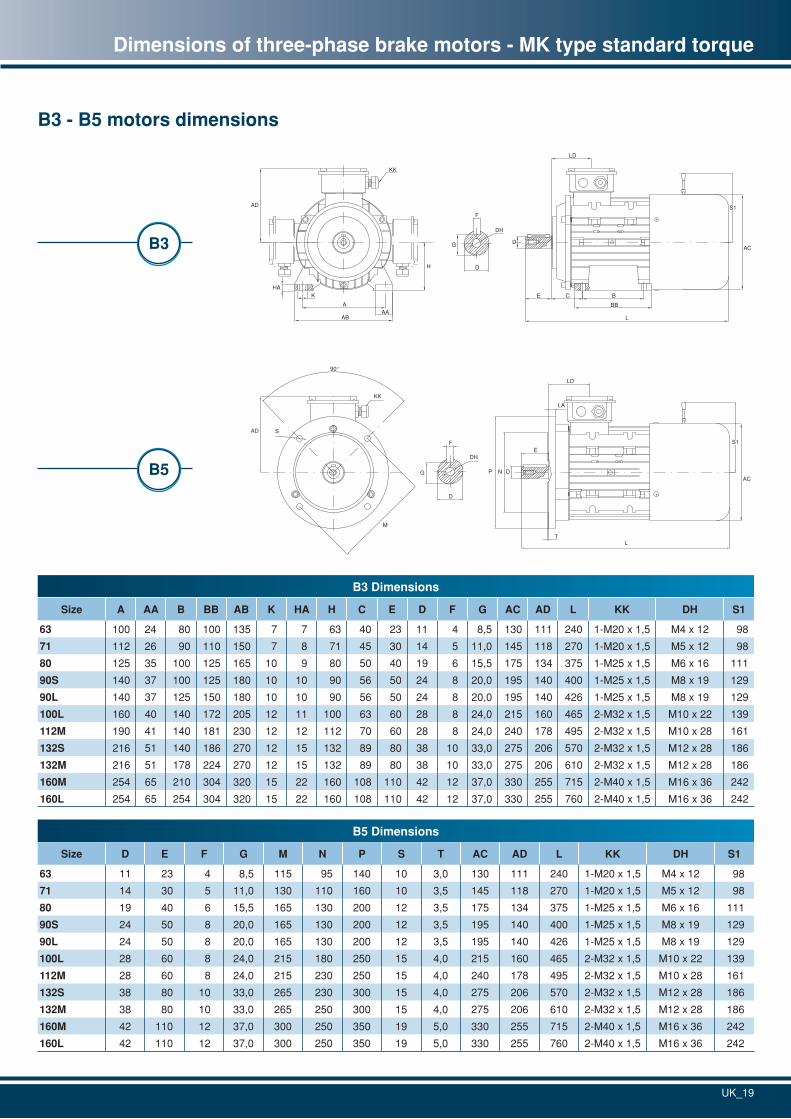
Dimensions of three-phase brake motors - MK type standard torque
B3 - B5 motors dimensions
B5
KK
A
AB
E C B
L
DAC
AD
H
DH
D
F
HAK
G
BB
LD
AA
S1
B3
KK
90°
S
M
AD
DH
D
F
G
E
L
P N D
T
AC
LD
LA
S1
B3 Dimensions
Size A AA B BB AB K HA H C E D F G AC AD L KK DH S1
63 100 24 80 100 135 7 7 63 40 23 11 4 8,5 130 111 240 1-M20 x 1,5 M4 x 12 98
71 112 26 90 110 150 7 8 71 45 30 14 5 11,0 145 118 270 1-M20 x 1,5 M5 x 12 98
80 125 35 100 125 165 10 9 80 50 40 19 6 15,5 175 134 375 1-M25 x 1,5 M6 x 16 111
90S 140 37 100 125 180 10 10 90 56 50 24 8 20,0 195 140 400 1-M25 x 1,5 M8 x 19 129
90L 140 37 125 150 180 10 10 90 56 50 24 8 20,0 195 140 426 1-M25 x 1,5 M8 x 19 129
100L 160 40 140 172 205 12 11 100 63 60 28 8 24,0 215 160 465 2-M32 x 1,5 M10 x 22 139
112M 190 41 140 181 230 12 12 112 70 60 28 8 24,0 240 178 495 2-M32 x 1,5 M10 x 28 161
132S 216 51 140 186 270 12 15 132 89 80 38 10 33,0 275 206 570 2-M32 x 1,5 M12 x 28 186
132M 216 51 178 224 270 12 15 132 89 80 38 10 33,0 275 206 610 2-M32 x 1,5 M12 x 28 186
160M 254 65 210 304 320 15 22 160 108 110 42 12 37,0 330 255 715 2-M40 x 1,5 M16 x 36 242
160L 254 65 254 304 320 15 22 160 108 110 42 12 37,0 330 255 760 2-M40 x 1,5 M16 x 36 242
B5 Dimensions
Size D E F G M N P S T AC AD L KK DH S1
63 11 23 4 8,5 115 95 140 10 3,0 130 111 240 1-M20 x 1,5 M4 x 12 98
71 14 30 5 11,0 130 110 160 10 3,5 145 118 270 1-M20 x 1,5 M5 x 12 98
80 19 40 6 15,5 165 130 200 12 3,5 175 134 375 1-M25 x 1,5 M6 x 16 111
90S 24 50 8 20,0 165 130 200 12 3,5 195 140 400 1-M25 x 1,5 M8 x 19 129
90L 24 50 8 20,0 165 130 200 12 3,5 195 140 426 1-M25 x 1,5 M8 x 19 129
100L 28 60 8 24,0 215 180 250 15 4,0 215 160 465 2-M32 x 1,5 M10 x 22 139
112M 28 60 8 24,0 215 230 250 15 4,0 240 178 495 2-M32 x 1,5 M10 x 28 161
132S 38 80 10 33,0 265 230 300 15 4,0 275 206 570 2-M32 x 1,5 M12 x 28 186
132M 38 80 10 33,0 265 250 300 15 4,0 275 206 610 2-M32 x 1,5 M12 x 28 186
160M 42 110 12 37,0 300 250 350 19 5,0 330 255 715 2-M40 x 1,5 M16 x 36 242
160L 42 110 12 37,0 300 250 350 19 5,0 330 255 760 2-M40 x 1,5 M16 x 36 242
UK_20
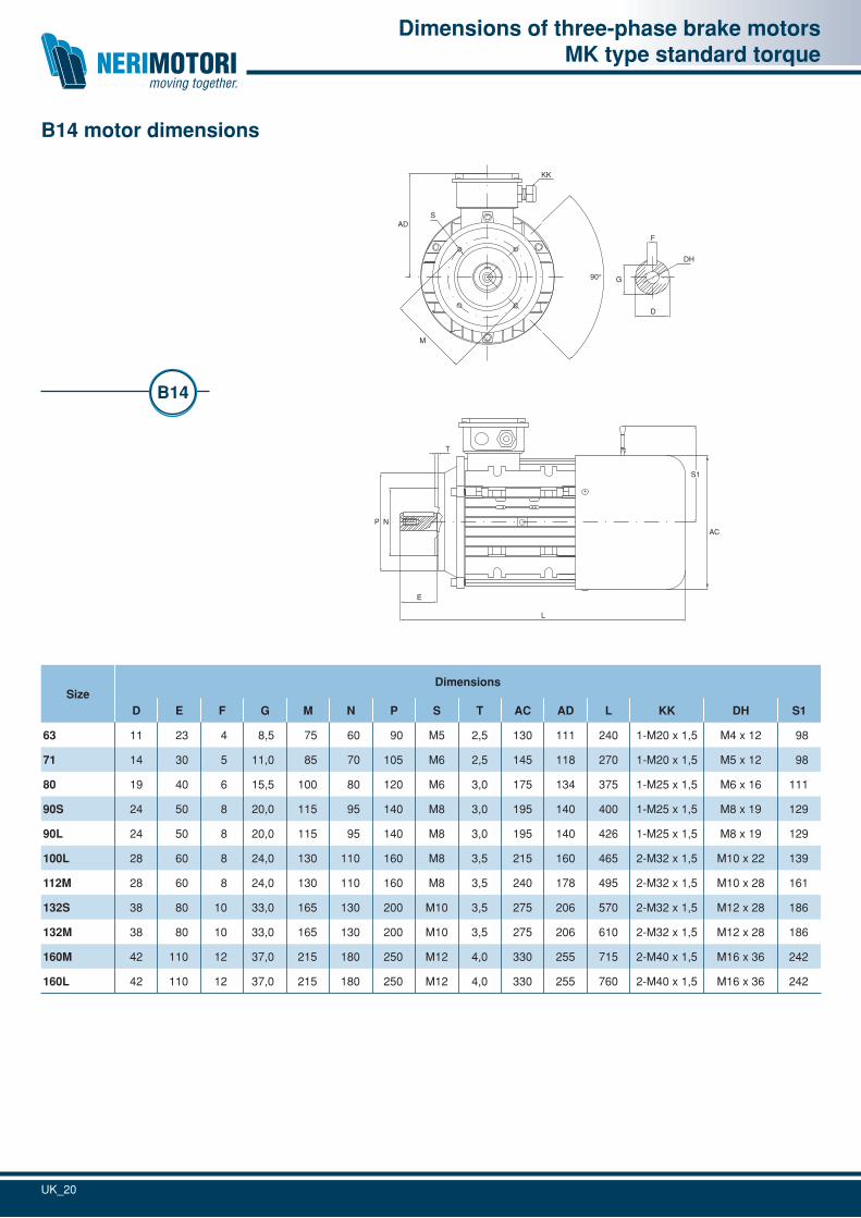
B14 motor dimensions
Dimensions of three-phase brake motorsMK type standard torque
L
E
T
NPAC
KK
90°
ADS
M
DH
D
F
G
S1
L
E
T
NPAC
KK
90°
ADS
M
DH
D
F
G
S1
B14
SizeDimensions
D E F G M N P S T AC AD L KK DH S1
63 11 23 4 8,5 75 60 90 M5 2,5 130 111 240 1-M20 x 1,5 M4 x 12 98
71 14 30 5 11,0 85 70 105 M6 2,5 145 118 270 1-M20 x 1,5 M5 x 12 98
80 19 40 6 15,5 100 80 120 M6 3,0 175 134 375 1-M25 x 1,5 M6 x 16 111
90S 24 50 8 20,0 115 95 140 M8 3,0 195 140 400 1-M25 x 1,5 M8 x 19 129
90L 24 50 8 20,0 115 95 140 M8 3,0 195 140 426 1-M25 x 1,5 M8 x 19 129
100L 28 60 8 24,0 130 110 160 M8 3,5 215 160 465 2-M32 x 1,5 M10 x 22 139
112M 28 60 8 24,0 130 110 160 M8 3,5 240 178 495 2-M32 x 1,5 M10 x 28 161
132S 38 80 10 33,0 165 130 200 M10 3,5 275 206 570 2-M32 x 1,5 M12 x 28 186
132M 38 80 10 33,0 165 130 200 M10 3,5 275 206 610 2-M32 x 1,5 M12 x 28 186
160M 42 110 12 37,0 215 180 250 M12 4,0 330 255 715 2-M40 x 1,5 M16 x 36 242
160L 42 110 12 37,0 215 180 250 M12 4,0 330 255 760 2-M40 x 1,5 M16 x 36 242
UK_21
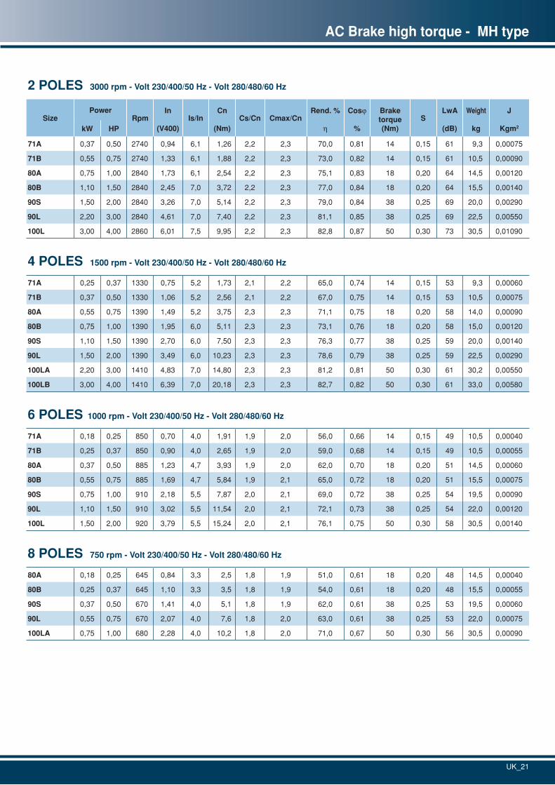
AC Brake high torque - MH type
2 POLES 3000 rpm - Volt 230/400/50 Hz - Volt 280/480/60 Hz
SizePower
RpmIn
(V400)Is/In
Cn
(Nm)Cs/Cn Cmax/Cn
Rend. %
h
Cosj
%
Brake torque(Nm)
SLwA
(dB)
Weight
kg
J
Kgm2kW HP
71A 0,37 0,50 2740 0,94 6,1 1,26 2,2 2,3 70,0 0,81 14 0,15 61 9,3 0,00075
71B 0,55 0,75 2740 1,33 6,1 1,88 2,2 2,3 73,0 0,82 14 0,15 61 10,5 0,00090
80A 0,75 1,00 2840 1,73 6,1 2,54 2,2 2,3 75,1 0,83 18 0,20 64 14,5 0,00120
80B 1,10 1,50 2840 2,45 7,0 3,72 2,2 2,3 77,0 0,84 18 0,20 64 15,5 0,00140
90S 1,50 2,00 2840 3,26 7,0 5,14 2,2 2,3 79,0 0,84 38 0,25 69 20,0 0,00290
90L 2,20 3,00 2840 4,61 7,0 7,40 2,2 2,3 81,1 0,85 38 0,25 69 22,5 0,00550
100L 3,00 4,00 2860 6,01 7,5 9,95 2,2 2,3 82,8 0,87 50 0,30 73 30,5 0,01090
4 POLES 1500 rpm - Volt 230/400/50 Hz - Volt 280/480/60 Hz
71A 0,25 0,37 1330 0,75 5,2 1,73 2,1 2,2 65,0 0,74 14 0,15 53 9,3 0,00060
71B 0,37 0,50 1330 1,06 5,2 2,56 2,1 2,2 67,0 0,75 14 0,15 53 10,5 0,00075
80A 0,55 0,75 1390 1,49 5,2 3,75 2,3 2,3 71,1 0,75 18 0,20 58 14,0 0,00090
80B 0,75 1,00 1390 1,95 6,0 5,11 2,3 2,3 73,1 0,76 18 0,20 58 15,0 0,00120
90S 1,10 1,50 1390 2,70 6,0 7,50 2,3 2,3 76,3 0,77 38 0,25 59 20,0 0,00140
90L 1,50 2,00 1390 3,49 6,0 10,23 2,3 2,3 78,6 0,79 38 0,25 59 22,5 0,00290
100LA 2,20 3,00 1410 4,83 7,0 14,80 2,3 2,3 81,2 0,81 50 0,30 61 30,2 0,00550
100LB 3,00 4,00 1410 6,39 7,0 20,18 2,3 2,3 82,7 0,82 50 0,30 61 33,0 0,00580
6 POLES 1000 rpm - Volt 230/400/50 Hz - Volt 280/480/60 Hz
71A 0,18 0,25 850 0,70 4,0 1,91 1,9 2,0 56,0 0,66 14 0,15 49 10,5 0,00040
71B 0,25 0,37 850 0,90 4,0 2,65 1,9 2,0 59,0 0,68 14 0,15 49 10,5 0,00055
80A 0,37 0,50 885 1,23 4,7 3,93 1,9 2,0 62,0 0,70 18 0,20 51 14,5 0,00060
80B 0,55 0,75 885 1,69 4,7 5,84 1,9 2,1 65,0 0,72 18 0,20 51 15,5 0,00075
90S 0,75 1,00 910 2,18 5,5 7,87 2,0 2,1 69,0 0,72 38 0,25 54 19,5 0,00090
90L 1,10 1,50 910 3,02 5,5 11,54 2,0 2,1 72,1 0,73 38 0,25 54 22,0 0,00120
100L 1,50 2,00 920 3,79 5,5 15,24 2,0 2,1 76,1 0,75 50 0,30 58 30,5 0,00140
8 POLES 750 rpm - Volt 230/400/50 Hz - Volt 280/480/60 Hz
80A 0,18 0,25 645 0,84 3,3 2,5 1,8 1,9 51,0 0,61 18 0,20 48 14,5 0,00040
80B 0,25 0,37 645 1,10 3,3 3,5 1,8 1,9 54,0 0,61 18 0,20 48 15,5 0,00055
90S 0,37 0,50 670 1,41 4,0 5,1 1,8 1,9 62,0 0,61 38 0,25 53 19,5 0,00060
90L 0,55 0,75 670 2,07 4,0 7,6 1,8 2,0 63,0 0,61 38 0,25 53 22,0 0,00075
100LA 0,75 1,00 680 2,28 4,0 10,2 1,8 2,0 71,0 0,67 50 0,30 56 30,5 0,00090
UK_22
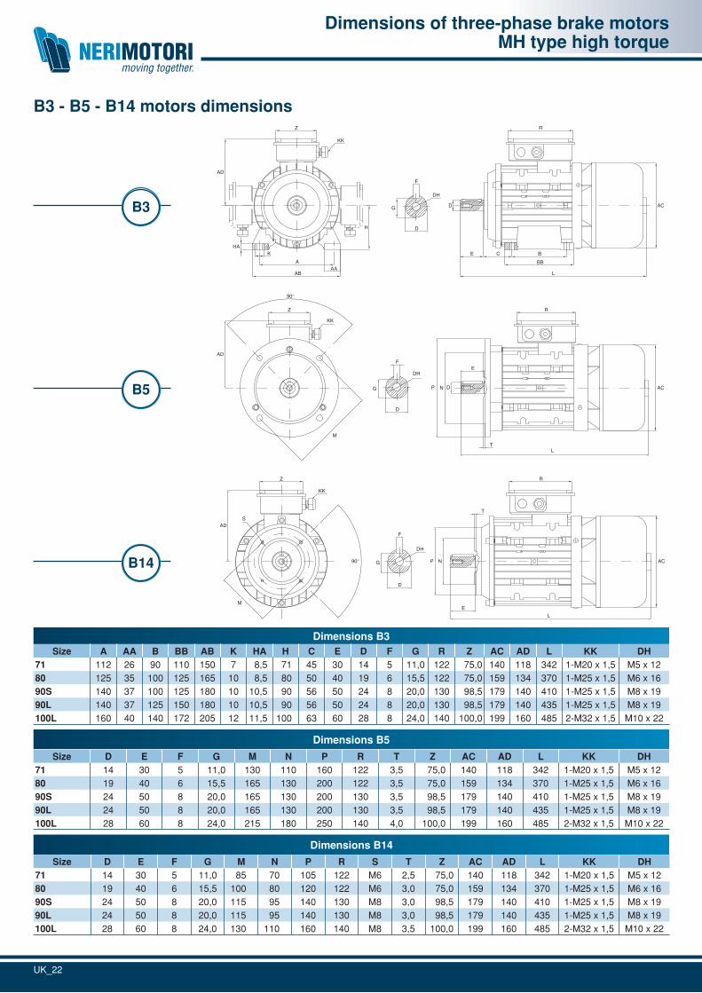
Dimensions of three-phase brake motorsMH type high torque
B3 - B5 - B14 motors dimensions
B14
KK
LE
T
DH
D
F
90°
ADS
NP AC
M
G
RZ
B3
KK
A
AB
E C B
L
D AC
AD
H
DH
D
F
HAK
G
BBAA
RZ
B5
KK
E
L
90°
DH
D
F
M
P N D
T
AC
AD
G
RZ
Dimensions B5
Size D E F G M N P R T Z AC AD L KK DH71 14 30 5 11,0 130 110 160 122 3,5 75,0 140 118 342 1-M20 x 1,5 M5 x 1280 19 40 6 15,5 165 130 200 122 3,5 75,0 159 134 370 1-M25 x 1,5 M6 x 1690S 24 50 8 20,0 165 130 200 130 3,5 98,5 179 140 410 1-M25 x 1,5 M8 x 1990L 24 50 8 20,0 165 130 200 130 3,5 98,5 179 140 435 1-M25 x 1,5 M8 x 19100L 28 60 8 24,0 215 180 250 140 4,0 100,0 199 160 485 2-M32 x 1,5 M10 x 22
Dimensions B14
Size D E F G M N P R S T Z AC AD L KK DH71 14 30 5 11,0 85 70 105 122 M6 2,5 75,0 140 118 342 1-M20 x 1,5 M5 x 1280 19 40 6 15,5 100 80 120 122 M6 3,0 75,0 159 134 370 1-M25 x 1,5 M6 x 1690S 24 50 8 20,0 115 95 140 130 M8 3,0 98,5 179 140 410 1-M25 x 1,5 M8 x 1990L 24 50 8 20,0 115 95 140 130 M8 3,0 98,5 179 140 435 1-M25 x 1,5 M8 x 19100L 28 60 8 24,0 130 110 160 140 M8 3,5 100,0 199 160 485 2-M32 x 1,5 M10 x 22
Dimensions B3Size A AA B BB AB K HA H C E D F G R Z AC AD L KK DH
71 112 26 90 110 150 7 8,5 71 45 30 14 5 11,0 122 75,0 140 118 342 1-M20 x 1,5 M5 x 1280 125 35 100 125 165 10 8,5 80 50 40 19 6 15,5 122 75,0 159 134 370 1-M25 x 1,5 M6 x 1690S 140 37 100 125 180 10 10,5 90 56 50 24 8 20,0 130 98,5 179 140 410 1-M25 x 1,5 M8 x 1990L 140 37 125 150 180 10 10,5 90 56 50 24 8 20,0 130 98,5 179 140 435 1-M25 x 1,5 M8 x 19100L 160 40 140 172 205 12 11,5 100 63 60 28 8 24,0 140 100,0 199 160 485 2-M32 x 1,5 M10 x 22
UK_23
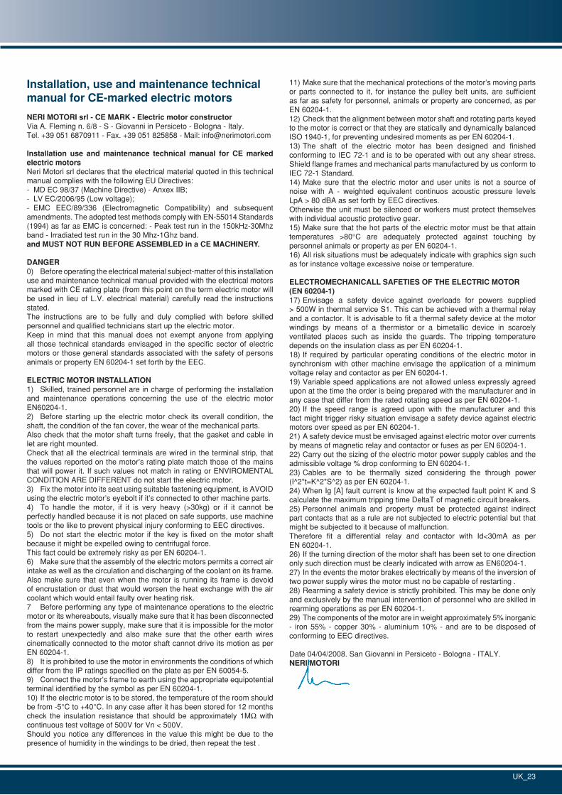
11) Make sure that the mechanical protections of the motor’s moving parts or parts connected to it, for instance the pulley belt units, are sufficient as far as safety for personnel, animals or property are concerned, as per EN 60204-1.12) Check that the alignment between motor shaft and rotating parts keyed to the motor is correct or that they are statically and dynamically balanced ISO 1940-1, for preventing undesired moments as per EN 60204-1.13) The shaft of the electric motor has been designed and finished conforming to IEC 72-1 and is to be operated with out any shear stress. Shield flange frames and mechanical parts manufactured by us conform to IEC 72-1 Standard.14) Make sure that the electric motor and user units is not a source of noise with A - weighted equivalent continuos acoustic pressure levels LpA > 80 dBA as set forth by EEC directives.Otherwise the unit must be silenced or workers must protect themselves with individual acoustic protective gear.15) Make sure that the hot parts of the electric motor must be that attain temperatures >80°C are adequately protected against touching by personnel animals or property as per EN 60204-1.16) All risk situations must be adequately indicate with graphics sign such as for instance voltage excessive noise or temperature.
ELECTROMECHANICALL SAFETIES OF THE ELECTRIC MOTOR(EN 60204-1)17) Envisage a safety device against overloads for powers supplied > 500W in thermal service S1. This can be achieved with a thermal relay and a contactor. It is advisable to fit a thermal safety device at the motor windings by means of a thermistor or a bimetallic device in scarcely ventilated places such as inside the guards. The tripping temperature depends on the insulation class as per EN 60204-1.18) If required by particular operating conditions of the electric motor in synchronism with other machine envisage the application of a minimum voltage relay and contactor as per EN 60204-1.19) Variable speed applications are not allowed unless expressly agreed upon at the time the order is being prepared with the manufacturer and in any case that differ from the rated rotating speed as per EN 60204-1.20) If the speed range is agreed upon with the manufacturer and this fact might trigger risky situation envisage a safety device against electric motors over speed as per EN 60204-1.21) A safety device must be envisaged against electric motor over currents by means of magnetic relay and contactor or fuses as per EN 60204-1.22) Carry out the sizing of the electric motor power supply cables and the admissible voltage % drop conforming to EN 60204-1.23) Cables are to be thermally sized considering the through power (I^2*t=K^2*S^2) as per EN 60204-1.24) When Ig [A] fault current is know at the expected fault point K and S calculate the maximum tripping time DeltaT of magnetic circuit breakers.25) Personnel animals and property must be protected against indirect part contacts that as a rule are not subjected to electric potential but that might be subjected to it because of malfunction.Therefore fit a differential relay and contactor with Id<30mA as per EN 60204-1.26) If the turning direction of the motor shaft has been set to one direction only such direction must be clearly indicated with arrow as EN60204-1.27) In the events the motor brakes electrically by means of the inversion of two power supply wires the motor must no be capable of restarting .28) Rearming a safety device is strictly prohibited. This may be done only and exclusively by the manual intervention of personnel who are skilled in rearming operations as per EN 60204-1.29) The components of the motor are in weight approximately 5% inorganic - iron 55% - copper 30% - aluminium 10% - and are to be disposed of conforming to EEC directives.
Date 04/04/2008. San Giovanni in Persiceto - Bologna - ITALY.NERI MOTORI
Installation, use and maintenance technical manual for CE-marked electric motors
NERI MOTORI srl - CE MARK - Electric motor constructorVia A. Fleming n. 6/8 - S - Giovanni in Persiceto - Bologna - Italy.Tel. +39 051 6870911 - Fax. +39 051 825858 - Mail: [email protected]
Installation use and maintenance technical manual for CE marked electric motorsNeri Motori srl declares that the electrical material quoted in this technical manual complies with the following EU Directives:- MD EC 98/37 (Machine Directive) - Anxex IIB;- LV EC/2006/95 (Low voltage);- EMC EEC/89/336 (Electromagnetic Compatibility) and subsequent amendments. The adopted test methods comply with EN-55014 Standards (1994) as far as EMC is concerned: - Peak test run in the 150kHz-30Mhz band - Irradiated test run in the 30 Mhz-1Ghz band.and MUST NOT RUN BEFORE ASSEMBLED in a CE MACHINERy.
DANGER0) Before operating the electrical material subject-matter of this installation use and maintenance technical manual provided with the electrical motors marked with CE rating plate (from this point on the term electric motor will be used in lieu of L.V. electrical material) carefully read the instructions stated.The instructions are to be fully and duly complied with before skilled personnel and qualified technicians start up the electric motor.Keep in mind that this manual does not exempt anyone from applying all those technical standards envisaged in the specific sector of electric motors or those general standards associated with the safety of persons animals or property EN 60204-1 set forth by the EEC.
ELECTRIC MOTOR INSTALLATION1) Skilled, trained personnel are in charge of performing the installation and maintenance operations concerning the use of the electric motor EN60204-1.2) Before starting up the electric motor check its overall condition, the shaft, the condition of the fan cover, the wear of the mechanical parts.Also check that the motor shaft turns freely, that the gasket and cable in let are right mounted.Check that all the electrical terminals are wired in the terminal strip, that the values reported on the motor’s rating plate match those of the mains that will power it. If such values not match in rating or ENVIROMENTAL CONDITION ARE DIFFERENT do not start the electric motor.3) Fix the motor into its seat using suitable fastening equipment, is AVOID using the electric motor’s eyebolt if it’s connected to other machine parts.4) To handle the motor, if it is very heavy (>30kg) or if it cannot be perfectly handled because it is not placed on safe supports, use machine tools or the like to prevent physical injury conforming to EEC directives.5) Do not start the electric motor if the key is fixed on the motor shaft because it might be expelled owing to centrifugal force.This fact could be extremely risky as per EN 60204-1.6) Make sure that the assembly of the electric motors permits a correct air intake as well as the circulation and discharging of the coolant on its frame. Also make sure that even when the motor is running its frame is devoid of encrustation or dust that would worsen the heat exchange with the air coolant which would entail faulty over heating risk.7 Before performing any type of maintenance operations to the electric motor or its whereabouts, visually make sure that it has been disconnected from the mains power supply, make sure that it is impossible for the motor to restart unexpectedly and also make sure that the other earth wires cinematically connected to the motor shaft cannot drive its motion as per EN 60204-1.8) It is prohibited to use the motor in environments the conditions of which differ from the IP ratings specified on the plate as per EN 60054-5.9) Connect the motor’s frame to earth using the appropriate equipotential terminal identified by the symbol as per EN 60204-1.10) If the electric motor is to be stored, the temperature of the room should be from -5°C to +40°C. In any case after it has been stored for 12 months check the insulation resistance that should be approximately 1MW with continuous test voltage of 500V for Vn < 500V.Should you notice any differences in the value this might be due to the presence of humidity in the windings to be dried, then repeat the test .
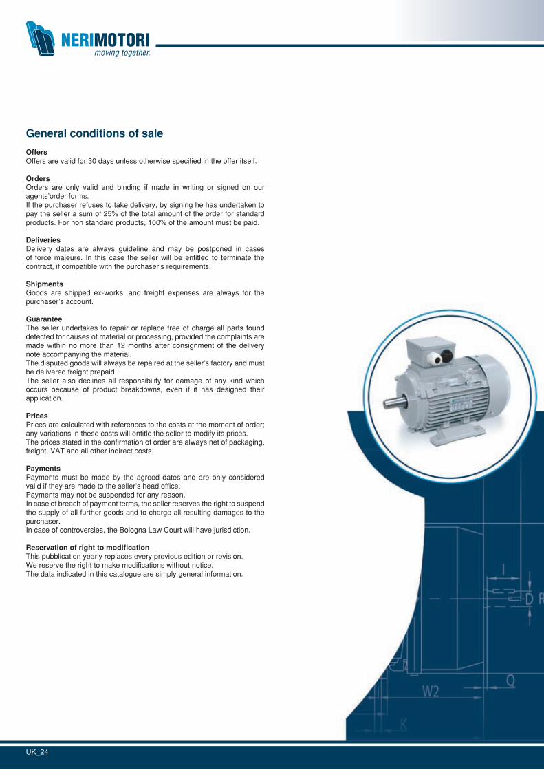
General conditions of sale
OffersOffers are valid for 30 days unless otherwise specified in the offer itself.
OrdersOrders are only valid and binding if made in writing or signed on our agents’order forms.If the purchaser refuses to take delivery, by signing he has undertaken to pay the seller a sum of 25% of the total amount of the order for standard products. For non standard products, 100% of the amount must be paid.
DeliveriesDelivery dates are always guideline and may be postponed in cases of force majeure. In this case the seller will be entitled to terminate the contract, if compatible with the purchaser’s requirements.
ShipmentsGoods are shipped ex-works, and freight expenses are always for the purchaser’s account.
GuaranteeThe seller undertakes to repair or replace free of charge all parts found defected for causes of material or processing, provided the complaints are made within no more than 12 months after consignment of the delivery note accompanying the material.The disputed goods will always be repaired at the seller’s factory and must be delivered freight prepaid.The seller also declines all responsibility for damage of any kind which occurs because of product breakdowns, even if it has designed their application.
PricesPrices are calculated with references to the costs at the moment of order; any variations in these costs will entitle the seller to modify its prices.The prices stated in the confirmation of order are always net of packaging, freight, VAT and all other indirect costs.
PaymentsPayments must be made by the agreed dates and are only considered valid if they are made to the seller’s head office.Payments may not be suspended for any reason.In case of breach of payment terms, the seller reserves the right to suspend the supply of all further goods and to charge all resulting damages to the purchaser.In case of controversies, the Bologna Law Court will have jurisdiction.
Reservation of right to modificationThis pubblication yearly replaces every previous edition or revision.We reserve the right to make modifications without notice.The data indicated in this catalogue are simply general information.
UK_24