Embed Size (px)
Citation preview
MOTORI AUTOFRENANTIBRAKE MOTORS
Catalogo Catalogue
2
HFF
HFZ
HFV
2005
63 ... 200Motore asincrono trifasecon freno a c.a.Asynchronous three-phasemotor with a.c. brake
63 ... 200Motore asincrono trifasecon freno a c.c.Asynchronous three-phasemotor with d.c. brake
63 ... 160SMotore asincrono trifase (e monofase)con freno di sicurezza a c.c.Asynchronous three-phase (and single-phase) motor with d.c. safety brake
C US
®
2
Motori elettrici autofrenanti
Gamma di motori autofrenanti vasta e completa per tipologia (HFF,HFZ, HFV), grandezza ed esecuzioni, idonea a risolvere tutte le pro-blematiche degli azionamenti con motore asincrono trifase emonofase autofrenante con freno a mancanza di alimentazioneProdotto robusto e affidabileDocumentazione innovativa per completezza e rigorePotenze 0,045 ... 37 kWSingola polarità 2, 4, 6, 8 poli 230 Y 400 V 50 Hz (grandezze 63 ...160S) e 400 V 50 Hz (grandezze 100 ... 200)Doppia polarità 2.4, 4.6, 4.8, 6.8 poli 400 V 50 Hz (grandezze 63 ...200) e 2.6, 2.8, 2.12 poli 400 V 50 Hz (grandezze 63 ... 132)Grandezze 63 ... 132 anche con potenze superiori (contrassegnate da *)a quelle previste dalle norme.Classe isolamento F; classe sovratemperatura B/F per tutti i motori asingola polarità con potenza normalizzata, F per i rimanentiForme costruttive IM B3 (grand. 80 ... 200 sempre predisposte), IM B5normali e speciali, IM B14 e corrispondenti forme costruttive verticaliProtezione IP 54 per grand. 63 ... 160S e IP 55 per grand. 160 ... 200Costruzione (elettrica e meccanica) particolarmente robusta persopportare le sollecitazioni termiche e torsionali alterne di avviamentoe di frenatura; cuscinetti adeguatamente dimensionatiScudi e flange con attacchi di serraggio «in appoggio» e montatisulla carcassa con accoppiamento «stretto»Dimensionamento elettromagnetico opportunamente studiato per con-sentire elevata capacità di accelerazione (elevata freq. di avv.) e buonaregolarità di avviamento (curve caratteristiche poco «insellate»)
Motori trifase grandezze 80 ... 200, 2 e 4 poli, 400 V 50 Hz (soloIC 411) a rendimento aumentato eff2.
Guarnizioni d’attrito senza amiantoScatola morsettiera ampia e metallica, alimentazione freno indifferen-temente diretta o separataIdoneità al funzionamento con inverterAmpia disponibilità di esecuzioni per ogni esigenza
I motori grandezze 63 ... 160S sono fornibili in esecuzione certi-ficata a norme CSA e UL
I motori HFZ sono fornibili in esecuzione certificata, per uso inzone con atmosfere potenzialmente esplosive, secondo la diret-tiva ATEX 94/9/CE: categorie 3G e 3D (zone 2 e 22).
HFF Motore autofrenante asincrono trifase con freno a c.a.Doppia superficie frenante, momento frenante elevato (normalmenteMf 2MN) e registrabile con continuitàMassima prontezza e precisione di sblocco e frenatura (caratteristicidel freno a c.a.) e massima frequenza di frenaturaElevata capacità di lavoro di frenaturaMassima frequenza di avviamento per il motore (lo sblocco del freno ètalmente rapido da consentire un avviamento completamente liberoanche con elevate frequenze di avviamento)Particolarmente idoneo a impieghi nei quali sono richieste frenaturepotenti e rapidissime nonché elevato numero di interventi
HFZ Motore autofrenante asincrono trifase con freno a c.c.Doppia superficie frenante, momento frenante proporzionato almomento motore (normalmente Mf ≈ 2MN) e registrabile a gradiniMassima silenziosità e progressività di intervento (sia all’avviamentoche in frenata) grazie alla minore rapidità (tipica del freno a c.c.) del-l’àncora (più leggera e meno veloce nell’impatto): il motore parte leg-germente frenato quindi con maggiore progressività; buona rapidità disblocco e frenatura; possibilità di accentuare la rapidità, sia allo sbloc-co (con il raddrizzatore rapido) sia alla frenata, con apertura dell’ali-mentazione del lato c.c.Elevata capacità di lavoro di frenatura ma inferiore a quella del tipoHFF nel caso di elevatissime frequenze di interventoAmpia disponibilità di esecuzioni speciali (volano, encoder, servoven-tilatore, servoventilatore ed encoder, leva di sblocco con ritorno auto-matico, protezioni superiori a IP 55: IP 56, IP 65.)Particolarmente idoneo a impieghi nei quali sono richiesti frenate eavviamenti regolari e silenziosi e, al tempo stesso, frenatura con buonarapidità e precisione e numero elevato di interventi
HFV Motore autofrenante asincrono trifase (e monofase) confreno di sicurezza a c.c. con ingombro ridottoIngombro motore ridottissimo, quasi uguale a quello di un motore nonautofrenante; massima economicitàSingola superficie frenante, momento frenante fisso (normal. Mf ≈ MN)Elevata capacità di lavoro di frenatura per singola frenata grazie alla ven-tola di ghisa (che funge anche da disco di frenatura) opportunamentedimensionata che garantisce lo smaltimento di elevate energie di frenaturaDisponibile anche per alimentazione monofaseParticolarmente adatta alle macchine da taglio, per arresti di sicurez-za, come freno di stazionamento, ecc.
C US
®
Electric brake motors
Brake motors in a wide and comprehensive range of types (HFF,HFZ, HFV), sizes and designs, suitable to solve every applicationproblem of the drives with asynchronous three-phase and single-phase brake motor with braking in case of failure of supplyStrong and reliable productInnovating, complete and rigorous documentationPowers 0,045 ... 37 kWSingle-speed 2, 4, 6, 8 poles 230 Y 400 V 50 Hz (sizes 63 ... 160S) and 400 V 50 Hz (sizes 100 ... 200)Two-speed 2.4, 4.6, 4.8, 6.8 poles 400 V 50 Hz (sizes 63 ... 200) and 2.6,2.8, 2.12 poles 400 V 50 Hz (sizes 63 ... 132)Sizes 63 ... 132 available also with higher powers (marked by*) thanthe ones foreseen by the standards.Class F insulation; temperature rise class B/F for all single-speed motorsat standard power, F for remaining motorsMounting positions IM B3 (sizes 80 ... 200 always pre-arranged), standard andnon-standard IM B5, IM B14 and corresponding vertical mounting positionsIP 54 protection for sizes 63 ... 160S and IP 55 for sizes 160 ... 200Particularly strong construction (both electrical and mechanical) towithstand alternating torsional and thermic stresses of starting and brak-ing; duly proportioned bearings«Supported» tightening attachments of endshields and flanges fittedon casing with «tight» couplingElectromagnetic sizing especially studied to allow high accelerationcapacity (high frequency of starting) and uniform starting (slightly«sagged» characteristic curves)
Improved efficiency three-phase motors, sizes 80 ... 200, 2 and4 poles, 400 V 50 Hz (IC 411 only), available according to eff2class limits.
Asbestos-free friction surfacesWide metallic terminal box, possibility of direct or separate brake supplySuitable for operation with inverterDesigns available for every application need
Motor sizes 63 ... 160S can be supplied in certified design to CSAand UL standards
HFZ motors are available in certified design, for use in zone withpotentially explosive atmospheres according to directive ATEX94/9/CE: categories 3G and 3D (zones 2 and 22).
HFF Asynchronous three-phase brake motor with a.c. brakeDouble braking surface, high braking torque (usually Mf 2MN) andadjustable with continuityMaximum quickness and precision in releasing and braking (typical ofa.c. brake) and maximum frequency of brakingHigh braking capacityMaximum frequency of starting for the motor (rapidity in brake releasingallows a completely free start also at high frequencies of starting)Particularly suitable for applications requiring strong and very rapidbrakings together with a high number of starts
HFZ Asynchronous three-phase brake motor with d.c. brakeDouble braking surface, braking torque proportioned to motor torque(usually Mf ≈ 2MN) and adjustable per stepMaximum reduced noise level and operation progressivity (both at start-ing and braking) thanks to a lower rapidity (typical of d.c. brake) of theanchor (which is lighter and less quick in the impact): motor starts slight-ly braked i.e. with greater progressivity; good release and braking rapid-ity; possibility to increase rapidity, both in releasing (with rapid rectifier)and braking, with supply opening on d.c. sideHigh braking capacity but lower than the one of HFF type in case of veryhigh frequencies of startingWide range of non-standard designs (flywheel, encoder, independentcooling fan, independent cooling fan and encoder, hand lever for manualrelease with automatic return, protections higher than IP 55: IP 56, IP 65.)Particularly suitable for applications requiring regular and low-noisestarting and braking and, at the same time, braking with good rapidityand precision and high number of starts
HFV Asynchronous three-phase (and single-phase) brake motorwith d.c. safety brake with reduced overall dimensionVery reduced motor overall dimensions, which are nearly the same of anon-braking motor; maximum economySingle braking surface, fixed braking torque (usually Mf ≈ MN)High braking capacity for each braking thanks to cast iron fan (whichalso acts as brake disk) especially sized in order to achieve the dissipa-tion of high braking energiesAlso available for single-phase supplyParticularly suitable for cutting machines, safety stops, as parkingbrake, etc.
C US
®
3
HFF
HFV
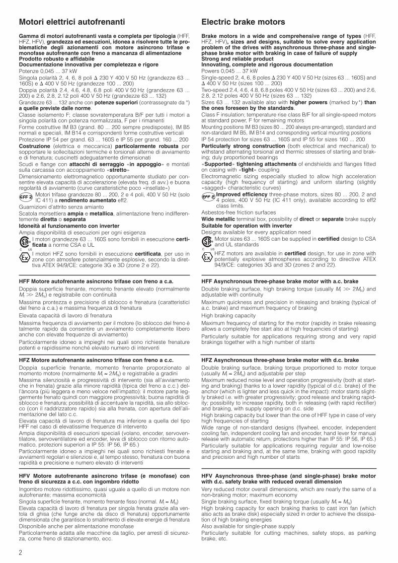
Normale Encoder Servoventilatore Servoventilatore Volanoed encoder
Standard Encoder Independent Independent cooling Flywheelcooling fan fan and encoder
63 ... 160S
160 ... 200
63 ... 160S
160 ... 200
63 ... 160S
HFZ
63 ... 160S 160 ... 200

4
Nella stesura del catalogo è stata dedicata la massima attenzione alfine di assicurare l’accuratezza dei dati, tuttavia non si possono ac-cettare responsabilità per eventuali errori, omissioni o dati non ag-giornati.Gli schemi di copertina raffigurano i motori completi di alcune esecu-zioni a richiesta: albero motore bloccato assialmente (per HFF eHFV), anelli di tenuta, leva di sblocco manuale con ritorno automati-co, guaina antipolvere e V-ring.
Every care has been taken in the drawing up of the catalogue toensure the accuracy of the information contained in this publication,however no responsibility can be accepted for any errors, omissionsor not updated data.Cover schemes represent motors comprehensive of some designson request: driving shaft axially fastened (for HFF and HFV), sealrings, lever for manual release with automatic return, dust-proofgaiter and V-ring.
5
Indice
1. Simboli
2. Designazione
3. Caratteristiche3.1 Caratteristiche generali3.2 Tipi di servizio3.3 Calcoli di verifica e di valutazione3.4 Variazioni delle caratteristiche nominali3.5 Carichi radiali e assiali3.6 Livelli sonori3.7 Funzionamento con inverter3.8 Tolleranze3.9 Norme specifiche
4. HFF Motore autofrenante asincronotrifase con freno a c.a.
4.1 Caratteristiche specifiche motore HFF4.2 Programma di fabbricazione motore HFF4.3 Dimensioni motore HFF
5. HFZ Motore autofrenante asincronotrifase con freno a c.c.
5.1 Caratteristiche specifiche motore HFZ5.2 Programma di fabbricazione motore HFZ5.3 Dimensioni motore HFZ
6. HFV Motore autofrenante asincronotrifase (e monofase) con frenodi sicurezza a c.c.
6.1 Caratteristiche specifiche motore HFV6.2 Programma di fabbricazione motore HFV6.3 Dimensioni motore HFV
7. Esecuzioni speciali e accessori
(compreso CSA e UL, ATEX)
8. Installazione e manutenzione8.1 Avvertenze generali sulla sicurezza8.2 Installazione: indicazioni generali8.3 Collegamento motore8.4 Freno del motore HFF8.5 Freno del motore HFZ8.6 Freno del motore HFV8.7 Collegamento equipaggiamenti ausiliari8.8 Tavole delle parti di ricambio
9. Targa
C US
®
Index
1. Symbols
2. Designation
3. Specifications3.1 Main specifications3.2 Duty types3.3 Verifying and evaluating calculations3.4 Variations of nominal specifications3.5 Radial and axial loads3.6 Sound levels3.7 Running with inverter3.8 Tolerances3.9 Specific standards
4. HFF Asynchronous three-phasebrake motor with a.c. brake
4.1 HFF motor specifications4.2 HFF motor manufacturing programme4.3 HFF motor dimensions
5. HFZ Asynchronous three-phasebrake motor with d.c. brake
5.1 HFZ motor specifications5.2 HFZ motor manufacturing programme5.3 HFZ motor dimensions
6. HFV Asynchronous three-phase(and single-phase) brake motorwith d.c. safety brake
6.1 HFV motor specifications6.2 HFV motor manufacturing programme6.3 HFV motor dimensions
7. Non-standard designs and accesso-ries( CSA and UL, ATEX included)
8. Installation and maintenance8.1 General safety instructions8.2 Installation: general directions8.3 Motor connection8.4 HFF motor brake8.5 HFZ motor brake8.6 HFV motor brake8.7 Auxiliary equipments connection8.8 Spare parts tables
9. Name plate
C US
®
6
6
7
18
32
44
56
69
81
HFZ
HFV
HFF
1. Simboli 1. Symbols
6
2. Designazione 2. Designation
1) Per frequenza e tensioni diverse da quelle indicate ved. cap. 7.(1).2) Disponibili anche nelle corrispondenti forme costruttive ad asse verticale.*) Indicare in «Esecuzione speciale» il codice «Due avvolgimenti separati».
1) May frequency and voltage differ from those stated above, see ch. 7.(1).2) Also available relevant mounting positions with vertical shaft.*) Indicate in «Non-standard design»: «Two separate windings» code.
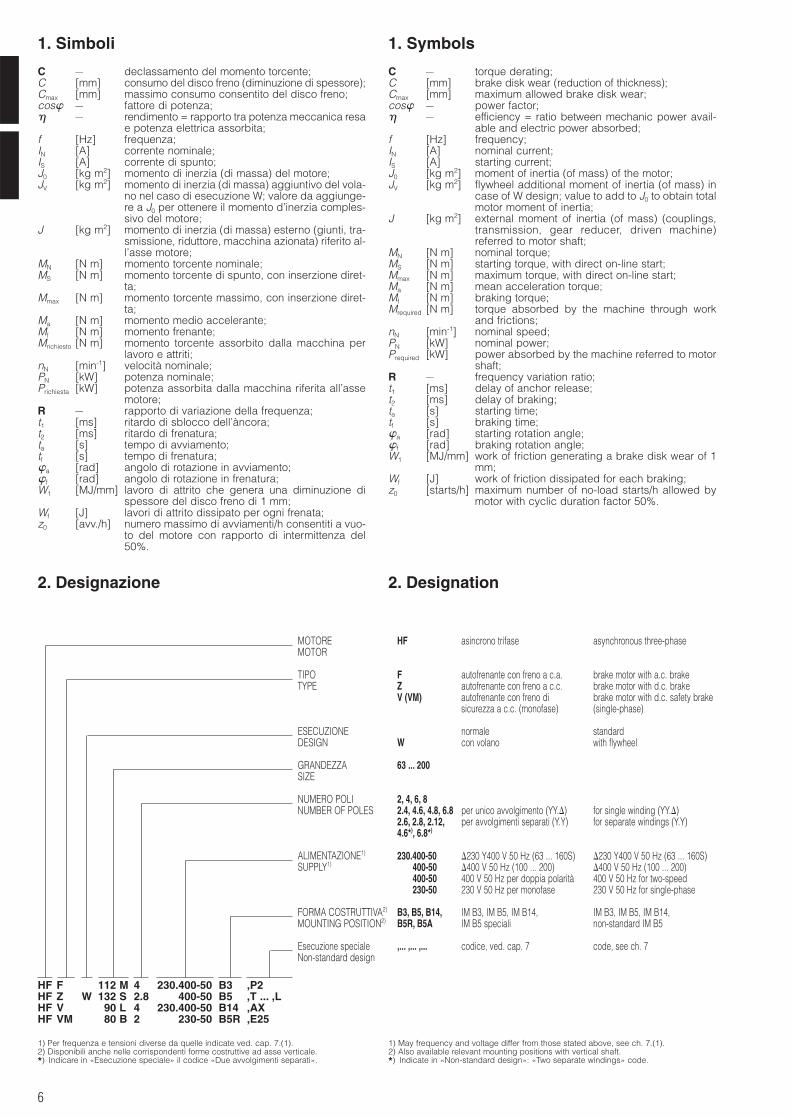
MOTOREMOTOR
TIPOTYPE
ESECUZIONEDESIGN
GRANDEZZASIZE
NUMERO POLINUMBER OF POLES
ALIMENTAZIONE1)
SUPPLY1)
FORMA COSTRUTTIVA2)
MOUNTING POSITION2)
Esecuzione specialeNon-standard design
,... ,... ,... codice, ved. cap. 7 code, see ch. 7
B3, B5, B14, IM B3, IM B5, IM B14, IM B3, IM B5, IM B14,B5R, B5A IM B5 speciali non-standard IM B5
230.400-50 230 Y400 V 50 Hz (63 ... 160S) 230 Y400 V 50 Hz (63 ... 160S)400-50 400 V 50 Hz (100 ... 200) 400 V 50 Hz (100 ... 200)400-50 400 V 50 Hz per doppia polarità 400 V 50 Hz for two-speed230-50 230 V 50 Hz per monofase 230 V 50 Hz for single-phase
2, 4, 6, 82.4, 4.6, 4.8, 6.8 per unico avvolgimento (YY.) for single winding (YY.)2.6, 2.8, 2.12, per avvolgimenti separati (Y.Y) for separate windings (Y.Y)4.6*), 6.8*)
63 ... 200
normale standardW con volano with flywheel
F autofrenante con freno a c.a. brake motor with a.c. brakeZ autofrenante con freno a c.c. brake motor with d.c. brakeV (VM) autofrenante con freno di brake motor with d.c. safety brake
sicurezza a c.c. (monofase) (single-phase)
HF asincrono trifase asynchronous three-phase
HF F 112 M 4 230.400-50 B3 ,P2HF Z W 132 S 2.8 400-50 B5 ,T ... ,LHF V 90 L 4 230.400-50 B14 ,AXHF VM 80 B 2 230-50 B5R ,E25
C – declassamento del momento torcente;C [mm] consumo del disco freno (diminuzione di spessore);Cmax [mm] massimo consumo consentito del disco freno;cos – fattore di potenza; – rendimento = rapporto tra potenza meccanica resa
e potenza elettrica assorbita;f [Hz] frequenza;IN [A] corrente nominale;IS [A] corrente di spunto;J0 [kg m2] momento di inerzia (di massa) del motore;JV [kg m2] momento di inerzia (di massa) aggiuntivo del vola-
no nel caso di esecuzione W; valore da aggiunge-re a J0 per ottenere il momento d’inerzia comples-sivo del motore;
J [kg m2] momento di inerzia (di massa) esterno (giunti, tra-smissione, riduttore, macchina azionata) riferito al-l’asse motore;
MN [N m] momento torcente nominale;MS [N m] momento torcente di spunto, con inserzione diret-
ta;Mmax [N m] momento torcente massimo, con inserzione diret-
ta;Ma [N m] momento medio accelerante;Mf [N m] momento frenante;Mrichiesto [N m] momento torcente assorbito dalla macchina per
lavoro e attriti;nN [min-1] velocità nominale;PN [kW] potenza nominale;Prichiesta [kW] potenza assorbita dalla macchina riferita all’asse
motore;R – rapporto di variazione della frequenza;t1 [ms] ritardo di sblocco dell’àncora;t2 [ms] ritardo di frenatura;ta [s] tempo di avviamento;tf [s] tempo di frenatura;a [rad] angolo di rotazione in avviamento;f [rad] angolo di rotazione in frenatura;W1 [MJ/mm] lavoro di attrito che genera una diminuzione di
spessore del disco freno di 1 mm;Wf [J] lavori di attrito dissipato per ogni frenata;z0 [avv./h] numero massimo di avviamenti/h consentiti a vuo-
to del motore con rapporto di intermittenza del50%.
C – torque derating;C [mm] brake disk wear (reduction of thickness);Cmax [mm] maximum allowed brake disk wear;cos – power factor; – efficiency = ratio between mechanic power avail-
able and electric power absorbed;f [Hz] frequency;IN [A] nominal current;IS [A] starting current;J0 [kg m2] moment of inertia (of mass) of the motor;JV [kg m2] flywheel additional moment of inertia (of mass) in
case of W design; value to add to J0 to obtain totalmotor moment of inertia;
J [kg m2] external moment of inertia (of mass) (couplings,transmission, gear reducer, driven machine)referred to motor shaft;
MN [N m] nominal torque;MS [N m] starting torque, with direct on-line start;Mmax [N m] maximum torque, with direct on-line start;Ma [N m] mean acceleration torque;Mf [N m] braking torque;Mrequired [N m] torque absorbed by the machine through work
and frictions;nN [min-1] nominal speed;PN [kW] nominal power;Prequired [kW] power absorbed by the machine referred to motor
shaft;R – frequency variation ratio;t1 [ms] delay of anchor release;t2 [ms] delay of braking;ta [s] starting time;tf [s] braking time;a [rad] starting rotation angle;f [rad] braking rotation angle;W1 [MJ/mm] work of friction generating a brake disk wear of 1
mm;Wf [J] work of friction dissipated for each braking;z0 [starts/h] maximum number of no-load starts/h allowed by
motor with cyclic duration factor 50%.
7
3. Caratteristiche 3. Specifications
3.1 Caratteristiche generaliMotori elettrici autofrenanti (freno a mancanza di alimentazione)in 3 tipi:HFF, motore asincrono trifase autofrenante con freno a c.a. a dop-pia superficie frenante, grandezze 63 ... 200;HFZ, motore asincrono trifase autofrenante con freno a c.c. a dop-pia superficie frenante, grandezze 63 ... 200;HFV, motore asincrono trifase (e monofase) autofrenante con frenodi sicurezza a c.c., a singola superficie frenante, con ingombroridotto, grandezze 63 ... 160S.Motore normalizzato con rotore a gabbia chiuso ventilato esterna-mente (metodo di raffreddamento IC 411), a singola polarità o a dop-pia polarità secondo tabelle seguenti:
motori a singola polarità (a una velocità)
3.1 Main specificationsElectric brake motors (braking in case of failure of supply) avail-able in 3 types:HFF, asynchronous three-phase brake motor with a.c. brake withdouble braking surface, sizes 63 ... 200;HFZ, asynchronous three-phase brake motor with d.c. brake withdouble braking surface, sizes 63 ... 200;HFV, asynchronous three-phase (and single-phase) brake motorwith d.c. safety brake, with single braking surface, with reducedoverall dimensions, sizes 63 ... 160S.Standardised motor with cage rotor, totally enclosed, externallyventilated (cooling system IC 411), single-speed or two-speedaccording to following tables:
single-speed motors (one speed)
motori a doppia polarità (a due velocità) two-speed motors (two speeds)
Potenza resa in servizio continuo (S1) e riferita a tensione e fre-quenza nominali, temperatura ambiente di -15 +40 °C e altitudinemassima 1 000 m.
Motori a rendimento aumentato eff2, trifase, a 2 e 4 poli, 400V 50 Hz (solo IC 411), grandezze 80 ... 200.
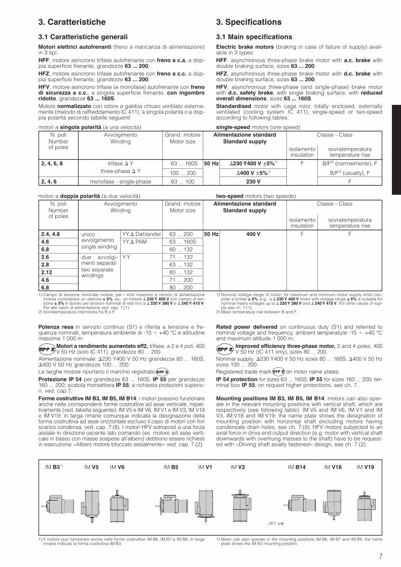
Alimentazione nominale: 230 Y400 V 50 Hz grandezze 80 ... 160S,400 V 50 Hz grandezze 100 ... 200.Le targhe motore riportano il marchio registrato .Protezione IP 54 per grandezze 63 ... 160S, IP 55 per grandezze160 ... 200; scatola morsettiera IP 55; a richiesta protezioni superio-ri, ved. cap.7.Forme costruttive IM B3, IM B5, IM B14; i motori possono funzionareanche nelle corrispondenti forme costruttive ad asse verticale, rispet-tivamente (ved. tabella seguente): IM V5 e IM V6, IM V1 e IM V3, IM V18e IM V19; in targa rimane comunque indicata la designazione dellaforma costruttiva ad asse orizzontale escluso il caso di motori con foriscarico condensa, ved. cap. 7.(8). I motori HFV sottoposti a una forzaassiale in direzione uscente lato comando (es. motore ad asse verti-cale in basso con masse sospese all’albero) debbono essere richiestiin esecuzione «Albero motore bloccato assialmente» ved. cap. 7.(2).
Rated power delivered on continuous duty (S1) and referred tonominal voltage and frequency, ambient temperature -15 +40 °Cand maximum altitude 1 000 m.
Improved efficiency three-phase motor, 2 and 4 poles, 400V 50 Hz (IC 411 only), sizes 80 ... 200.
Nominal supply: 230 Y400 V 50 Hz sizes 80 ... 160S, 400 V 50 Hzsizes 100 ... 200.Registered trade mark on motor name plates.IP 54 protection for sizes 63 ... 160S, IP 55 for sizes 160 ... 200; ter-minal box IP 55; on request higher protections, see ch. 7.
Mounting positions IM B3, IM B5, IM B14; motors can also oper-ate in the relevant mounting positions with vertical shaft, which arerespectively (see following table): IM V5 and IM V6, IM V1 and IMV3, IM V18 and IM V19; the name plate shows the designation ofmounting position with horizontal shaft excluding motors havingcondensate drain holes, see ch. 7.(8). HFV motors subjected to anaxial force in drive end output direction (e.g. motor with vertical shaftdownwards with overhung masses to the shaft) have to be request-ed with «Driving shaft axially fastened» design, see ch. 7.(2).
1) Il motore può funzionare anche nelle forme costruttive IM B6, IM B7 e IM B8; in targarimane indicata la forma costruttiva IM B3.
1) Motor can also operate in the mounting positions IM B6, IM B7 and IM B8; the nameplate shows the IM B3 mounting position.
IM B31) IM V5 IM V6 IM B5 IM V1 IM V3 IM B14 IM V18 IM V19
N. poli Avvolgimento Grand. motore Alimentazione standard Classe - ClassNumber Winding Motor size Standard supplyof poles
2, 4, 6, 8 trifase Y 63 ... 160S 50 Hz 230 Y400 V ±5%1) F B/F2) (normalmente), Fthree-phase Y 100 ... 200 400 V ±5%1) B/F2) (usually), F
2, 4, 6 monofase - single-phase 63 ... 100 230 V F
isolamento sovratemperaturainsulation temperature rise
N. poli Avvolgimento Grand. motore Alimentazione standard Classe - ClassNumber Winding Motor size Standard supplyof poles
2.4, 4.8 YY. Dahlander 63 ... 200S 50 Hz 400 V F F4.6 YY. PAM 63 ... 160S6.8 80 ... 132S2.6 Y.Y 71 ... 132S2.8 63 ... 132S2.12 80 ... 132S4.6 71 ... 200S6.8 80 ... 200S
isolamento sovratemperaturainsulation temperature rise
unicoavvolgimentosingle winding
due avvolgi-menti separatitwo separatewindings
1) Campo di tensione nominale motore; per i limiti massimo e minimo di alimentazionemotore considerare un ulteriore ± 5%, es.: un motore 230 Y 400 V con campo di ten-sione ± 5% è idoneo per tensioni nominali di rete fino a 220 Y 380 V e 240 Y 415 V.Per altri valori di alimentazione ved. cap. 7.(1).
2) Sovratemperatura intermedia fra B e F.
1) Nominal voltage range of motor; for maximum and minimum motor supply limits con-sider a further ± 5%, e.g.: a 230 Y 400 V motor with voltage range ± 5% is suitable fornominal mains voltages up to 220 Y 380 V and 240 Y 415 V. For other values of sup-ply see ch. 7.(1).
2) Mean temperature rise between B and F.
8
3. Caratteristiche 3. Specifications
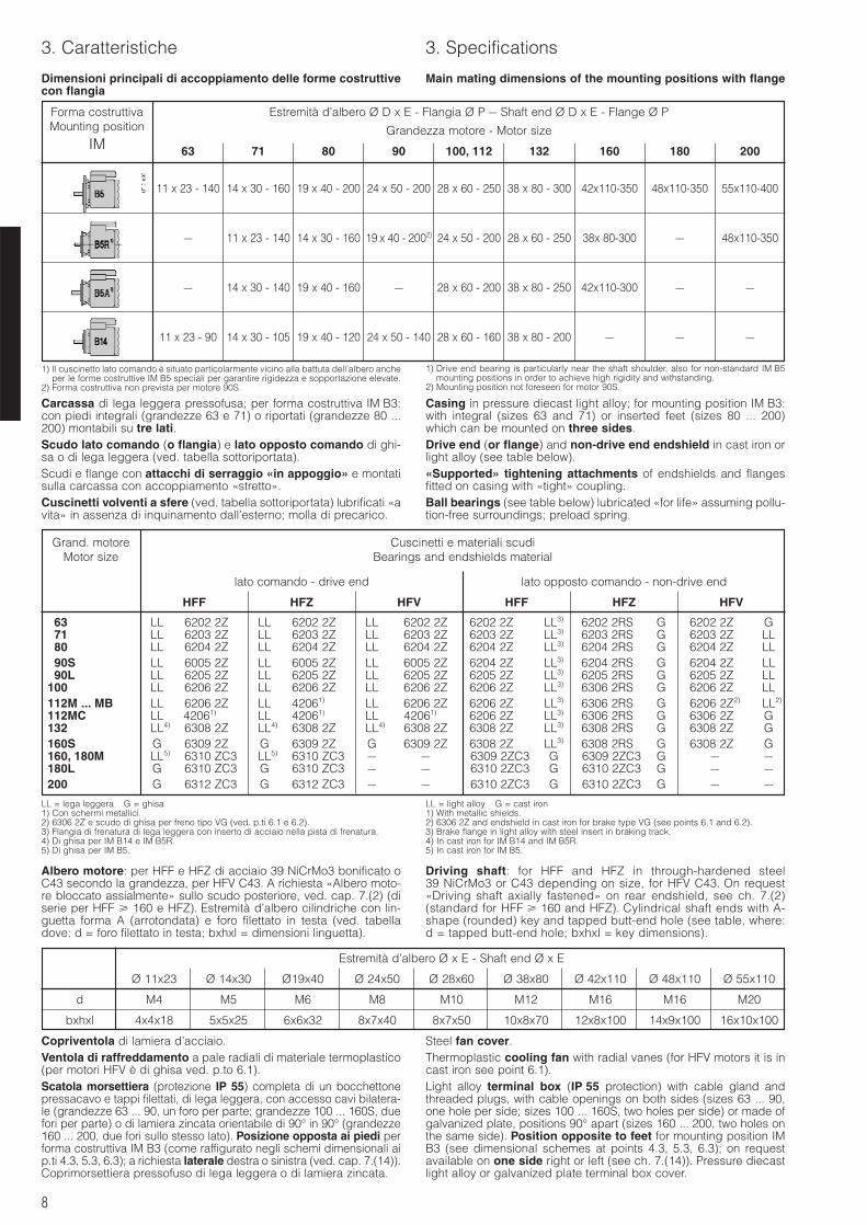
Dimensioni principali di accoppiamento delle forme costruttivecon flangia
Main mating dimensions of the mounting positions with flange
Forma costruttivaMounting position
IM
Estremità d’albero Ø D x E - Flangia Ø P – Shaft end Ø D x E - Flange Ø P
Grandezza motore - Motor size
63 71 80 90 100, 112 132 160 180 200
11 x 23 - 140 14 x 30 - 160 19 x 40 - 200 24 x 50 - 200 28 x 60 - 250 38 x 80 - 300 42x110-350 48x110-350 55x110-400
– 11 x 23 - 140 14 x 30 - 160 19 x 40 - 2002) 24 x 50 - 200 28 x 60 - 250 38x 80-300 – 48x110-350
– 14 x 30 - 140 19 x 40 - 160 – 28 x 60 - 200 38 x 80 - 250 42x110-300 – –
11 x 23 - 90 14 x 30 - 105 19 x 40 - 120 24 x 50 - 140 28 x 60 - 160 38 x 80 - 200 – – –
1) Il cuscinetto lato comando è situato particolarmente vicino alla battuta dell’albero ancheper le forme costruttive IM B5 speciali per garantire rigidezza e sopportazione elevate.
2) Forma costruttiva non prevista per motore 90S.
LL = lega leggera G = ghisa1) Con schermi metallici.2) 6306 2Z e scudo di ghisa per freno tipo VG (ved. p.ti 6.1 e 6.2).3) Flangia di frenatura di lega leggera con inserto di acciaio nella pista di frenatura.4) Di ghisa per IM B14 e IM B5R.5) Di ghisa per IM B5.
LL = light alloy G = cast iron1) With metallic shields.2) 6306 2Z and endshield in cast iron for brake type VG (see points 6.1 and 6.2).3) Brake flange in light alloy with steel insert in braking track.4) In cast iron for IM B14 and IM B5R.5) In cast iron for IM B5.
1) Drive end bearing is particularly near the shaft shoulder, also for non-standard IM B5mounting positions in order to achieve high rigidity and withstanding.
2) Mounting position not foreseen for motor 90S.
Carcassa di lega leggera pressofusa; per forma costruttiva IM B3:con piedi integrali (grandezze 63 e 71) o riportati (grandezze 80 ...200) montabili su tre lati.Scudo lato comando (o flangia) e lato opposto comando di ghi-sa o di lega leggera (ved. tabella sottoriportata).Scudi e flange con attacchi di serraggio «in appoggio» e montatisulla carcassa con accoppiamento «stretto».Cuscinetti volventi a sfere (ved. tabella sottoriportata) lubrificati «avita» in assenza di inquinamento dall’esterno; molla di precarico.
Casing in pressure diecast light alloy; for mounting position IM B3:with integral (sizes 63 and 71) or inserted feet (sizes 80 ... 200)which can be mounted on three sides.Drive end (or flange) and non-drive end endshield in cast iron orlight alloy (see table below).«Supported» tightening attachments of endshields and flangesfitted on casing with «tight» coupling.Ball bearings (see table below) lubricated «for life» assuming pollu-tion-free surroundings; preload spring.
Albero motore: per HFF e HFZ di acciaio 39 NiCrMo3 bonificato oC43 secondo la grandezza, per HFV C43. A richiesta «Albero moto-re bloccato assialmente» sullo scudo posteriore, ved. cap. 7.(2) (diserie per HFF 160 e HFZ). Estremità d’albero cilindriche con lin-guetta forma A (arrotondata) e foro filettato in testa (ved. tabelladove: d = foro filettato in testa; bxhxl = dimensioni linguetta).
Driving shaft: for HFF and HFZ in through-hardened steel39 NiCrMo3 or C43 depending on size, for HFV C43. On request«Driving shaft axially fastened» on rear endshield, see ch. 7.(2)(standard for HFF 160 and HFZ). Cylindrical shaft ends with A-shape (rounded) key and tapped butt-end hole (see table, where:d = tapped butt-end hole; bxhxl = key dimensions).
Copriventola di lamiera d’acciaio.Ventola di raffreddamento a pale radiali di materiale termoplastico(per motori HFV è di ghisa ved. p.to 6.1).Scatola morsettiera (protezione IP 55) completa di un bocchettonepressacavo e tappi filettati, di lega leggera, con accesso cavi bilatera-le (grandezze 63 ... 90, un foro per parte; grandezze 100 ... 160S, duefori per parte) o di lamiera zincata orientabile di 90° in 90° (grandezze160 ... 200, due fori sullo stesso lato). Posizione opposta ai piedi performa costruttiva IM B3 (come raffigurato negli schemi dimensionali aip.ti 4.3, 5.3, 6.3); a richiesta laterale destra o sinistra (ved. cap. 7.(14)).Coprimorsettiera pressofuso di lega leggera o di lamiera zincata.
Steel fan cover.Thermoplastic cooling fan with radial vanes (for HFV motors it is incast iron see point 6.1).Light alloy terminal box (IP 55 protection) with cable gland andthreaded plugs, with cable openings on both sides (sizes 63 ... 90,one hole per side; sizes 100 ... 160S, two holes per side) or made ofgalvanized plate, positions 90° apart (sizes 160 ... 200, two holes onthe same side). Position opposite to feet for mounting position IMB3 (see dimensional schemes at points 4.3, 5.3, 6.3); on requestavailable on one side right or left (see ch. 7.(14)). Pressure diecastlight alloy or galvanized plate terminal box cover.
Grand. motore Cuscinetti e materiali scudiMotor size Bearings and endshields material
lato comando - drive end lato opposto comando - non-drive end
HFF HFZ HFV HFF HFZ HFV
63 LL 6202 2ZC LL 6202 2ZC LL 6202 2Z 6202 2ZCC LL3) 6202 2RSC G 6202 2Z.. G71 LL 6203 2ZC LL 6203 2ZC LL 6203 2Z 6203 2ZCC LL3) 6203 2RSC G 6203 2Z.. LL80 LL 6204 2ZC LL 6204 2ZC LL 6204 2Z 6204 2ZCC LL3) 6204 2RSC G 6204 2Z.. LL90S LL 6005 2ZC LL 6005 2ZC LL 6005 2Z 6204 2ZCC LL3) 6204 2RSC G 6204 2Z.. LL90L LL 6205 2ZC LL 6205 2ZC LL 6205 2Z 6205 2ZCC LL3) 6205 2RSC G 6205 2Z.. LL
100 LL 6206 2ZC LL 6206 2ZC LL 6206 2Z 6206 2ZCC LL3) 6306 2RSC G 6206 2Z.. LL112M ... MB LL 6206 2ZC LL 42061)000 LL 6206 2Z 6206 2ZCC LL3) 6306 2RSC G 6206 2Z2) LL2)
112MC LL 42061)0C0 LL 42061)000 LL 42061) C 6206 2ZCC LL3) 6306 2RSC G 6306 2Z.. G132 LL4) 6308 2ZC LL4) 6308 2ZC LL4) 6308 2Z 6308 2ZCC LL3) 6308 2RSC G 6308 2Z.. G160S G 6309 2ZC G 6309 2ZC G 6309 2Z 6308 2ZCC LL3) 6308 2RSC G 6308 2Z.. G160, 180M LL5) 6310 ZC3 LL5) 6310 ZC3 – – 6309 2ZC3 G 6309 2ZC3 G – –180L G 6310 ZC3 G 6310 ZC3 – – 6310 2ZC3 G 6310 2ZC3 G – –200 G 6312 ZC3 G 6312 ZC3 – – 6310 2ZC3 G 6310 2ZC3 G – –
Estremità d’albero Ø x E - Shaft end Ø x E
Ø 11x23 Ø 14x30 Ø19x40 Ø 24x50 Ø 28x60 Ø 38x80 Ø 42x110 Ø 48x110 Ø 55x110
d M4 M5 M6 M8 M10 M12 M16 M16 M20
bxhxl 4x4x18 5x5x25 6x6x32 8x7x40 8x7x50 10x8x70 12x8x100 14x9x100 16x10x100
9
3. Caratteristiche 3. Specifications
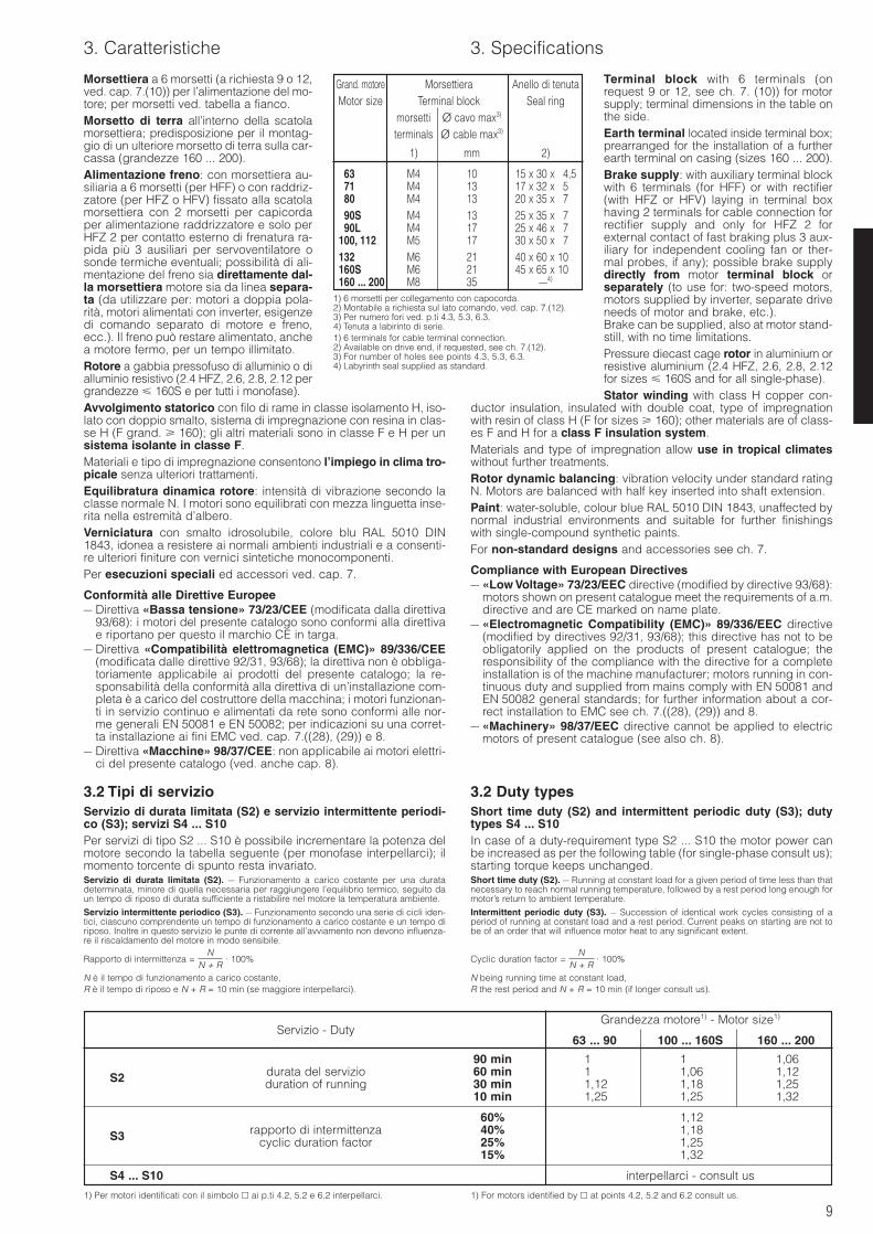
Morsettiera a 6 morsetti (a richiesta 9 o 12,ved. cap. 7.(10)) per l’alimentazione del mo-tore; per morsetti ved. tabella a fianco.Morsetto di terra all’interno della scatolamorsettiera; predisposizione per il montag-gio di un ulteriore morsetto di terra sulla car-cassa (grandezze 160 ... 200).Alimentazione freno: con morsettiera au-siliaria a 6 morsetti (per HFF) o con raddriz-zatore (per HFZ o HFV) fissato alla scatolamorsettiera con 2 morsetti per capicordaper alimentazione raddrizzatore e solo perHFZ 2 per contatto esterno di frenatura ra-pida più 3 ausiliari per servoventilatore osonde termiche eventuali; possibilità di ali-mentazione del freno sia direttamente dal-la morsettiera motore sia da linea separa-ta (da utilizzare per: motori a doppia pola-rità, motori alimentati con inverter, esigenzedi comando separato di motore e freno,ecc.). Il freno può restare alimentato, anchea motore fermo, per un tempo illimitato.Rotore a gabbia pressofuso di alluminio o dialluminio resistivo (2.4 HFZ, 2.6, 2.8, 2.12 pergrandezze 160S e per tutti i monofase).Avvolgimento statorico con filo di rame in classe isolamento H, iso-lato con doppio smalto, sistema di impregnazione con resina in clas-se H (F grand. 160); gli altri materiali sono in classe F e H per unsistema isolante in classe F.Materiali e tipo di impregnazione consentono l’impiego in clima tro-picale senza ulteriori trattamenti.Equilibratura dinamica rotore: intensità di vibrazione secondo laclasse normale N. I motori sono equilibrati con mezza linguetta inse-rita nella estremità d’albero.Verniciatura con smalto idrosolubile, colore blu RAL 5010 DIN1843, idonea a resistere ai normali ambienti industriali e a consenti-re ulteriori finiture con vernici sintetiche monocomponenti.Per esecuzioni speciali ed accessori ved. cap. 7.
Conformità alle Direttive Europee– Direttiva «Bassa tensione» 73/23/CEE (modificata dalla direttiva
93/68): i motori del presente catalogo sono conformi alla direttivae riportano per questo il marchio CE in targa.
– Direttiva «Compatibilità elettromagnetica (EMC)» 89/336/CEE(modificata dalle direttive 92/31, 93/68); la direttiva non è obbliga-toriamente applicabile ai prodotti del presente catalogo; la re-sponsabilità della conformità alla direttiva di un’installazione com-pleta è a carico del costruttore della macchina; i motori funzionan-ti in servizio continuo e alimentati da rete sono conformi alle nor-me generali EN 50081 e EN 50082; per indicazioni su una corret-ta installazione ai fini EMC ved. cap. 7.((28), (29)) e 8.
– Direttiva «Macchine» 98/37/CEE: non applicabile ai motori elettri-ci del presente catalogo (ved. anche cap. 8).
3.2 Tipi di servizioServizio di durata limitata (S2) e servizio intermittente periodi-co (S3); servizi S4 ... S10Per servizi di tipo S2 ... S10 è possibile incrementare la potenza delmotore secondo la tabella seguente (per monofase interpellarci); ilmomento torcente di spunto resta invariato.Servizio di durata limitata (S2). – Funzionamento a carico costante per una duratadeterminata, minore di quella necessaria per raggiungere l’equilibrio termico, seguito daun tempo di riposo di durata sufficiente a ristabilire nel motore la temperatura ambiente.
Servizio intermittente periodico (S3). – Funzionamento secondo una serie di cicli iden-tici, ciascuno comprendente un tempo di funzionamento a carico costante e un tempo diriposo. Inoltre in questo servizio le punte di corrente all’avviamento non devono influenza-re il riscaldamento del motore in modo sensibile.
Rapporto di intermittenza = · 100%
N è il tempo di funzionamento a carico costante,R è il tempo di riposo e N + R = 10 min (se maggiore interpellarci).
NN + R
Terminal block with 6 terminals (onrequest 9 or 12, see ch. 7. (10)) for motorsupply; terminal dimensions in the table onthe side.Earth terminal located inside terminal box;prearranged for the installation of a furtherearth terminal on casing (sizes 160 ... 200).Brake supply: with auxiliary terminal blockwith 6 terminals (for HFF) or with rectifier(with HFZ or HFV) laying in terminal boxhaving 2 terminals for cable connection forrectifier supply and only for HFZ 2 forexternal contact of fast braking plus 3 aux-iliary for independent cooling fan or ther-mal probes, if any); possible brake supplydirectly from motor terminal block orseparately (to use for: two-speed motors,motors supplied by inverter, separate driveneeds of motor and brake, etc.).Brake can be supplied, also at motor stand-still, with no time limitations.Pressure diecast cage rotor in aluminium orresistive aluminium (2.4 HFZ, 2.6, 2.8, 2.12for sizes 160S and for all single-phase).Stator winding with class H copper con-
ductor insulation, insulated with double coat, type of impregnationwith resin of class H (F for sizes 160); other materials are of class-es F and H for a class F insulation system.Materials and type of impregnation allow use in tropical climateswithout further treatments.Rotor dynamic balancing: vibration velocity under standard ratingN. Motors are balanced with half key inserted into shaft extension.Paint: water-soluble, colour blue RAL 5010 DIN 1843, unaffected bynormal industrial environments and suitable for further finishingswith single-compound synthetic paints.For non-standard designs and accessories see ch. 7.
Compliance with European Directives– «Low Voltage» 73/23/EEC directive (modified by directive 93/68):
motors shown on present catalogue meet the requirements of a.m.directive and are CE marked on name plate.
– «Electromagnetic Compatibility (EMC)» 89/336/EEC directive(modified by directives 92/31, 93/68); this directive has not to beobligatorily applied on the products of present catalogue; theresponsibility of the compliance with the directive for a completeinstallation is of the machine manufacturer; motors running in con-tinuous duty and supplied from mains comply with EN 50081 andEN 50082 general standards; for further information about a cor-rect installation to EMC see ch. 7.((28), (29)) and 8.
– «Machinery» 98/37/EEC directive cannot be applied to electricmotors of present catalogue (see also ch. 8).
3.2 Duty typesShort time duty (S2) and intermittent periodic duty (S3); dutytypes S4 ... S10In case of a duty-requirement type S2 ... S10 the motor power canbe increased as per the following table (for single-phase consult us);starting torque keeps unchanged.Short time duty (S2). – Running at constant load for a given period of time less than thatnecessary to reach normal running temperature, followed by a rest period long enough formotor’s return to ambient temperature.
Intermittent periodic duty (S3). – Succession of identical work cycles consisting of aperiod of running at constant load and a rest period. Current peaks on starting are not tobe of an order that will influence motor heat to any significant extent.
Cyclic duration factor = · 100%
N being running time at constant load,R the rest period and N + R = 10 min (if longer consult us).
NN + R
Grand. motore Morsettiera Anello di tenutaMotor size Terminal block Seal ring
morsetti Ø cavo max3)
terminals Ø cable max3)
1) mm 2)
63 M4 10 15 x 30 x 4,571 M4 13 17 x 32 x 5,580 M4 13 20 x 35 x 7,590S M4 13 25 x 35 x 7,590L M4 17 25 x 46 x 7,5
100, 112 M5 17 30 x 50 x 7,5132 M6 21 40 x 60 x 10,5160S M6 21 45 x 65 x 10,5160 ... 200 M8 35 –4)
1) 6 morsetti per collegamento con capocorda.2) Montabile a richiesta sul lato comando, ved. cap. 7.(12).3) Per numero fori ved. p.ti 4.3, 5.3, 6.3.4) Tenuta a labirinto di serie.1) 6 terminals for cable terminal connection.2) Available on drive end, if requested, see ch. 7.(12).3) For number of holes see points 4.3, 5.3, 6.3.4) Labyrinth seal supplied as standard.
Grandezza motore1) - Motor size1)
Servizio - Duty63 ... 90 100 ... 160S 160 ... 200
90 min 1 1 1,06
S2 durata del servizio 60 min 1 1,06 1,12duration of running 30 min 1,12 1,18 1,25
10 min 1,25 1,25 1,32
60% 1,12
S3 rapporto di intermittenza 40% 1,18cyclic duration factor 25% 1,25
15% 1,32
S4 ... S10 interpellarci - consult us
1) Per motori identificati con il simbolo ai p.ti 4.2, 5.2 e 6.2 interpellarci. 1) For motors identified by at points 4.2, 5.2 and 6.2 consult us.
10
3. Caratteristiche 3. Specifications
3.3 Calcoli di verifica e valutazioneLe principali verifiche necessarie affinché motore e freno possanosoddisfare le esigenze applicative consistono in:– dati il momento torcente richiesto e le inerzie applicate, la fre-
quenza di avviamento non deve superare il valore massimo am-messo dagli avvolgimenti del motore senza che si abbiano surri-scaldamenti;
– dato il numero di frenate/h, il lavoro di attrito per ogni frenaturanon deve superare il massimo valore ammesso dalla guarnizioned’attrito.
Ved. sotto le modalità di verifica.
Frequenza massima di avviamento zOrientativamente la massima frequenza di avviamento z, per untempo di avviamento 0,5 1 s e con inserzione diretta, è di 125avv./h per grandezze 63 ... 90, 63 avv./h per grandezze 100 ... 160S,16 avv./h per grandezze 160 ... 200; dimezzare i valori per motoriHFFW, HFZW, HFV, i quali, avendo J0 più elevato (per ottenere avvia-menti e arresti progressivi), possono fare un numero minore di avvia-menti a parità di condizioni.Quando è necessaria una frequenza di avviamento superiore verifi-care che:
z z0 · · K · [1 - ( )2· 0,6]
K = 1 se il motore, durante l’avviamento, deve vincere solo cari-chi inerziali;
K = 0,63 se il motore, durante l’avviamento, deve vincere anche ca-richi resistenti di attrito, di lavoro, di sollevamento, ecc.
Per motori a doppia polarità la verifica del valore z va fatta:– per la polarità bassa, se l’avviamento è a velocità alta, e conside-
rando il relativo valore di z0 e PN;– per entrambe le polarità se l’avviamento è a velocità bassa con suc-
cessiva commutazione a velocità alta e considerando i rispettivi valo-ri di z0 e PN, ma moltiplicando il valore di z0 della polarità bassa per2 (2.4, 4.8, 4.6, 6.8 poli), 1,8 (2.6 poli), 1,4 (2.8 poli), 1,25 (2.12 poli).
In caso di risultati insoddisfacenti o in presenza di frenature ipersin-crone frequenti la verifica può essere fatta con formule più detta-gliate: interpellarci.Per HFZ, nel caso di frequenza di avviamento elevata (z/z0 0,2 po-larità unica, z/z0 0,3 doppia polarità, purché z 1100 avv./h) pre-vedere l’impiego del raddrizzatore rapido RR1 (ved. cap. 7.(27)) peri motori che già non ne sono dotati.
Massimo lavoro di attrito per ogni frenatura Wf
Nel caso di un numero elevato di frenature/h (z 0,2 z0) o di inerzieapplicate molto elevate (J 10 J0) è necessario verificare che illavoro di attrito per ogni frenatura non superi il massimo valoreammesso Wfmax indicato ai p.ti 4.1, 5.1, 6.1 in funzione della fre-quenza di frenatura (per valori intermedi di frequenza impiegare ilvalore più basso o, all’occorrenza, interpolare):
per il calcolo di f ved. sotto.
Tempo di avviamento ta e angolo di rotazione del motore a
ta = [s] a = [rad]
Per calcoli più accurati sostituire a MS il momento medio accelerante, normalmenteMa ≈ 0,85 · MS.
Tempo di frenatura tf e angolo di rotazione del motore f
tf = [s] f = [rad]
Se Mrichiesto tende a trainare il motore (esempio carico sospeso) intro-durre nelle formule un numero negativo.La ripetitività di frenatura al variare della temperatura del freno edello stato di usura della guarnizione di attrito è, entro i limiti norma-li del traferro e dell’umidità ambiente e con adeguata apparecchia-tura elettrica, circa ± 0,1 · f.
Durata della guarnizione di attritoOrientativamente il numero di frenature tra due registrazioni deltraferro vale:
per il calcolo della periodicità di registrazione del traferro, il valo-re di C è dato dalla differenza tra i valori max e min del traferro; peril calcolo della durata totale del disco freno, il valore C è dato dalvalore massimo di consumo Cmax (ved. p.ti 4.1, 5.1, 6.1).
tf · nN
19,1(J0 + J) · nN
9,55 · (Mf + Mrichiesto)
ta · nN
19,1(J0 + J) · nN
9,55 · (MS - Mrichiesto)
Prichiesta
PN
J0
J0 + J
3.3 Verifying and evaluating calculationsMain necessary verifications so that motor and brake can satisfyapplication needs are:– given required torque and applied inertiae, frequency of starting
has not to exceed maximum value permissible by motor windingswithout overheatings;
– given number of brakings/h, work of friction for each brakinghas not to exceed maximum permissible value of friction surface.
See below verification modalities.
Maximum frequency of starting zAs a guide, maximum frequency of starting z, for a starting time 0,5 1 s and with direct on-line start, is 125 starts/h for sizes 63 ... 90,63 starts/h for sizes 100 ... 160S, 16 starts/h for sizes 160 ... 200;halve the values for motors HFFW, HFZW, HFV, which, having ahigher J0 (to get progressive starts and stops), can have a lowernumber of starts at the same conditions.When it is necessary to have a higher frequency of starting, verify that:
z z0 · · K · [1 - ( )2· 0,6]
K = 1 if motor, during the starting, must only overcome inertialloads;
K = 0,63 if motor, during the starting, must also overcome resistentfriction, work, lifting loads, etc.
For two-speed motors, verification of z value is as follows:– for the lower set of poles, if starting is at high speed, taking into
account relative z0 and PN values;– for both sets of poles, if starting is at low speed with subsequent
switch to high speed, taking into account relative z0 and PN values,though multiplying the z0 value of the lower set of poles by 2 (2.4,4.8, 4.6, 6.8 poles), 1,8 (2.6 poles), 1,4 (2.8 poles), 1,25 (2.12 poles).
Where results are unsatisfactory or where frequent hypersynchro-nous brakings occur, more detailed verification formulae can beutilised: consult us.For HFZ, in case of high frequency of starting (z/z0 0,2 single-speed, z/z0 0,3 two-speed, provided that z 1100 starts/h) fore-see the application of a rapid rectifier RR1 (see ch. 7.(27)) if motorsdo not have it.
Maximum work of friction for each braking Wf
In case of a high number of brakings/h (z 0,2 z0) or very high iner-tiae applied (J 10 J0) it is necessary to verify that work of frictionfor each braking does not exceed maximum permissible value ofWfmax as shown at points 4.1, 5.1, 6.1 according to frequency ofbraking (for intermediate values of frequency apply the lowest valueand interpolate, if necessary):
for the calculation of f see below.
Starting time ta and motor rotation angle a
ta = [s] a = [rad]
For more accurate calculations replace MS with a mean acceleration torque, usuallyMa ≈ 0,85 · MS.
Braking time tf and motor rotation angle f
tf = [s] f = [rad]
If Mrequired tends to pull the motor (e.g. overhung load) introduce anegative number in the formulae.Assuming a regular air-gap and ambient humidity and utilising suit-able electrical equipment, repetition of the braking action, as affect-ed by variaton in temperature of the brake and by the state of wearof friction surface, is approx. ± 0,1 · f.
Duration of friction surfaceAs a guide, the number of brakings permissible between succes-sive adjustments of the air-gap is given by the formula:
for the calculation of periodical air-gap adjustment, C value isgiven by the difference between max and min values of the air-gap;for total brake disk life calculation, C value is given by the maxi-mum wear value Cmax (see points 4.1, 5.1, 6.1).
tf · nN
19,1(J0 + J) · nN
9,55 · (Mf + Mrequired)
ta · nN
19,1(J0 + J) · nN
9,55 · (MS - Mrequired)
Prequired
PN
J0
J0 + J
;W1 · C · 106
Mf · f
Wfmax Mf · f [J]
11
3. Caratteristiche 3. Specifications
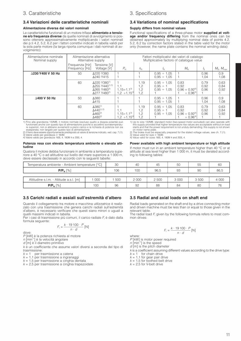
3.4 Variazioni delle caratteristiche nominaliAlimentazione diversa dai valori nominaliLe caratteristiche funzionali di un motore trifase alimentato a tensio-ne e/o frequenza diverse da quelle nominali di avvolgimento si pos-sono ottenere approssimativamente moltiplicando i valori nominalidei p.ti 4.2, 5.2, 6.2 per i fattori correttivi indicati in tabella validi perla sola parte motore (la targa riporta comunque i dati nominali di av-volgimento):
3.4 Variations of nominal specificationsSupply differs from nominal valuesFunctional specifications of a three-phase motor supplied at volt-age and/or frequency differing from the nominal ones can beobtained approximately by multiplying nominal data of points 4.2,5.2, 6.2 by correction factors stated in the table valid for the motoronly (however, the name plate contains the nominal winding data):
Alimentazione nominale Alimentazione alternativa Fattori moltiplicativi dei valori di catalogoNominal supply Alternative supply Multiplicative factors of catalogue value
Frequenza [Hz] Tensione [V]Frequency [Hz] Voltage [V] PN nN IN MN IS MS, Mmax
230 Y400 V 50 Hz 50 220 Y380 1,0 1 0,95 1,05 1 0,96 0,92240 Y415 1,0 1 0,95 1,05 1 1,04 1,08
60 220 Y3801) 1,0 1,19 0,95 1,05 0,83 0,79 0,63255 Y4401) 2) 1,1 1,2 0,95 1 0,92 0,92 0,84265 Y4602) 1,15÷1,13) 1,2 0,95 1,05 0,96 ÷ 0,923) 0,96 0,92277 Y4802) 1,21÷1,154) 1,2 1 1,09 ÷ 0,964) 1 1
400 V 50 Hz 50 380 1,0 1 0,95 1,05 1 0,96 0,92415 1,0 1 0,95 1,05 1 1,04 1,08
60 3801) 1,0 1,19 0,95 1,05 0,83 0,79 0,634401) 2) 1,1 1,2 0,95 1 0,92 0,92 0,844602) 1,15÷1,13) 1,2 0,95 1,05 0,96 ÷ 0,923) 0,96 0,924802) 1,21÷1,154) 1,2 1 1,01 ÷ 0,964) 1 1
1) Fino alla grandezza 132MB, il motore normale (escluso quello a doppia polarità) puòfunzionare anche con questo tipo di alimentazione purché si accettino sovratemperatu-re superiori, non si abbiano avviamenti a pieno carico e la richiesta di potenza non siaesasperata; non targato per questo tipo di alimentazione.
2) Il freno deve essere opportunamente predisposto al valore di tensione indicato, ved. cap. 7.(1).3) Valore valido per grandezza 160M.4) Valore valido per grandezze 160L 4, 180M 4 e 200L 4.
1) Up to size 132MB, standard motor (two-speed motor excluded) can also operate withthis supply provided that higher temperature rise values are acceptable without on-loadstarts and that the power requirement is not unduly demanding; this supply is not shownon motor name plate.
2) The brake must be especially prepared for the stated voltage values, see ch. 7.(1).3) Value valid for size 160M.4) Value valid for sizes 160L 4, 180M 4 and 200L 4.
Potenza resa con elevata temperatura ambiente o elevata alti-tudineQualora il motore debba funzionare in ambiente a temperatura supe-riore a 40 °C o ad altitudine sul livello del mare superiore a 1 000 m,deve essere declassato in accordo con le seguenti tabelle:
3.5 Carichi radiali e assiali sull’estremità d’alberoQuando il collegamento tra motore e macchina utilizzatrice è realiz-zato con una trasmissione che genera carichi radiali sull’estremitàd’albero, è necessario verificare che questi siano minori o uguali aquelli massimi indicati in tabella.Per i casi di trasmissione più comuni, il carico radiale Fr è dato dallaformula seguente:
Fr = [N]
dove:P [kW] è la potenza richiesta al motoren [min-1] è la velocità angolared [m] è il diametro primitivok è un coefficiente che assume valori diversi a seconda del tipo ditrasmissione:k = 1 per trasmissione a catenak = 1,1 per trasmissione a ingranaggik = 1,5 per trasmissione a cinghia dentatak = 2,5 per trasmissione a cinghia trapezoidale
k · 19 100 · Pn · d
3.5 Radial and axial loads on shaft endRadial loads generated on the shaft end by a drive connecting motorand driven machine must be less than or equal to those given in therelevant table.The radial load Fr given by the following formula refers to most com-mon drives:
Fr = [N]
where:P [kW] is motor power requiredn [min-1] is the speedd [m] is the pitch diameterk is a coefficient assuming different values according to the drive type:k = 1 for chain drivek = 1,1 for gear pair drivek = 1,5 for toothed belt drivek = 2,5 for V-belt drive
k · 19 100 · Pn · d
Power available with high ambient temperature or high altitudeIf motor must run in an ambient temperature higher than 40 °C or ataltitude at sea level higher than 1 000 m, it must be derated accord-ing to following tables:
Temperatura ambiente - Ambient temperature [°C] 30 40 45 50 55 60
P/PN [%] 106 100 96,5 93 90 86,5
Altitudine s.l.m. - Altitude a.s.l. [m] 1 000 1 500 2 000 2 500 3 000 3 500 4 000
P/PN [%] 100 96 92 88 84 80 76
12
3. Caratteristiche 3. Specifications
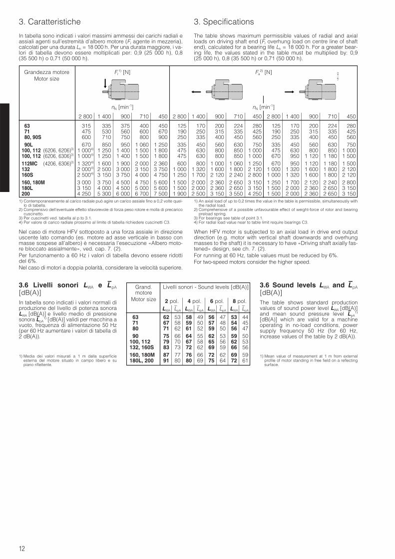
In tabella sono indicati i valori massimi ammessi dei carichi radiali eassiali agenti sull’estremità d’albero motore (Fr agente in mezzeria),calcolati per una durata Lh = 18 000 h. Per una durata maggiore, i va-lori di tabella devono essere moltiplicati per: 0,9 (25 000 h), 0,8 (35 500 h) o 0,71 (50 000 h).
The table shows maximum permissible values of radial and axialloads on driving shaft end (Fr overhung load on centre line of shaftend), calculated for a bearing life Lh = 18 000 h. For a greater bear-ing life, the values stated in the table must be multiplied by: 0,9 (25 000 h), 0,8 (35 500 h) or 0,71 (50 000 h).
Grandezza motore Fr1) [N] Fa
2) [N]Motor size
nN [min-1] nN [min-1]
2 800 1 400 900 710 450 2 800 1 400 900 710 450 2 800 1 400 900 710 450
63 3154) 335 375 400 450 125 170 200 224 280 125 170 200 224 28071 4754) 530 560 600 670 190 250 315 335 425 190 250 315 335 42580, 90S 6004) 710 750 800 900 250 335 400 450 560 250 335 400 450 56090L 6704) 850 950 1 060 1 250 335 450 560 630 750 335 450 560 630 750
100, 112 (6206, 6206)3) 1 0004) 1 250 1 400 1 500 1 800 475 630 800 850 1 000 475 630 800 850 1 000100, 112 (6206, 6306)3) 1 0004) 1 250 1 400 1 500 1 800 475 630 800 850 1 000 670 950 1 120 1 180 1 500112MC (4206, 6306)3) 1 3204) 1 600 1 900 2 000 2 360 600 800 1 000 1 060 1 250 670 950 1 120 1 180 1 500132 2 0004) 2 500 3 000 3 150 3 750 1 000 1 320 1 600 1 800 2 120 1 000 1 320 1 600 1 800 2 120160S 2 5004) 3 150 3 750 4 000 4 750 1 250 1 700 2 120 2 240 2 800 1 000 1 320 1 600 1 800 2 120160, 180M 3 0004) 3 750 4 500 4 750 5 600 1 500 2 000 2 360 2 650 3 150 1 250 1 700 2 120 2 240 2 800180L 3 1504) 4 000 4 500 5 000 5 600 1 500 2 000 2 360 2 650 3 150 1 500 2 000 2 360 2 650 3 150200 4 2504) 5 300 6 000 6 700 7 500 1 900 2 500 3 150 3 550 4 250 1 500 2 000 2 360 2 650 3 150
1) Contemporaneamente al carico radiale può agire un carico assiale fino a 0,2 volte quel-lo di tabella.
2) Comprensivo dell’eventuale effetto sfavorevole di forza peso rotore e molla di precaricocuscinetto.
3) Per cuscinetti ved. tabella al p.to 3.1.4) Per valore di carico radiale prossimo al limite di tabella richiedere cuscinetti C3.
1) An axial load of up to 0,2 times the value in the table is permissible, simultaneously withthe radial load.
2) Comprehensive of a possible unfavourable effect of weight-force of rotor and bearingpreload spring.
3) For bearings see table of point 3.1.4) For radial load value near to table limit require bearings C3.
Nel caso di motore HFV sottoposto a una forza assiale in direzioneuscente lato comando (es. motore ad asse verticale in basso conmasse sospese all’albero) è necessaria l’esecuzione «Albero moto-re bloccato assialmente», ved. cap. 7. (2).Per funzionamento a 60 Hz i valori di tabella devono essere ridottidel 6%.Nel caso di motori a doppia polarità, considerare la velocità superiore.
3.6 Livelli sonori LWA e L–pA
[dB(A)]In tabella sono indicati i valori normali diproduzione del livello di potenza sonoraLWA [dB(A)] e livello medio di pressionesonora L
–pA
1) [dB(A)] validi per macchina avuoto, frequenza di alimentazione 50 Hz(per 60 Hz aumentare i valori di tabella di2 dB(A)).
1) Media dei valori misurati a 1 m dalla superficieesterna del motore situato in campo libero e supiano riflettente.
When HFV motor is subjected to an axial load in drive end outputdirection (e.g. motor with vertical shaft downwards and overhungmasses to the shaft) it is necessary to have «Driving shaft axially fas-tened» design, see ch. 7. (2).For running at 60 Hz, table values must be reduced by 6%.For two-speed motors consider the higher speed.
3.6 Sound levels LWA and L–pA
[dB(A)]The table shows standard productionvalues of sound power level LWA [dB(A)]and mean sound pressure level L
–pA
1)
[dB(A)] which are valid for a machineoperating in no-load conditions, powersupply frequency 50 Hz (for 60 Hz,increase values of the table by 2 dB(A)).
1) Mean value of measurement at 1 m from externalprofile of motor standing in free field on a reflectingsurface.
Grand. Livelli sonori - Sound levels [dB(A)]motore
Motor size 2 pol. 4 pol. 6 pol. 8 pol.LWA L
–pA LWA L
–pA LWA L
–pA LWA L
–pA
63 62 53 58 49 56 47 53 4471 67 58 59 50 57 48 54 4580 71 62 61 52 59 50 56 4790 75 66 64 55 62 53 59 50
100, 112 79 70 67 58 65 56 62 53132, 160S 83 73 72 62 69 59 66 56160, 180M 87 77 76 66 72 62 69 59180L, 200 91 80 80 69 75 64 72 61
13
3. Caratteristiche 3. Specifications
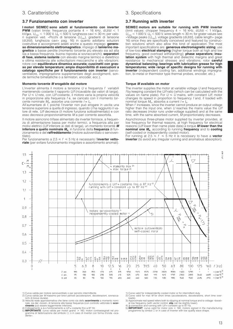
3.7 Funzionamento con inverterI motori SEIMEC sono adatti al funzionamento con inverterPWM (valori limite: frequenza portante 4 16 kHz, dU/dt 1kV/s, Umax 1 000 V, UN 500 V, lunghezza cavi 30 m; per valo-ri superiori ved. «Picchi di tensione (Umax), gradienti di tensione(dU/dt), lunghezza cavi» pag. 16) in quanto adottano soluzionicostruttive e accorgimenti adatti anche a questo impiego: genero-so dimensionamento elettromagnetico; impiego di lamierino ma-gnetico a basse perdite (momento torcente più elevato sia ad altasia a bassa frequenza, buona risposta ai sovraccarichi); separatoridi fase, sistema isolante con elevato margine termico e dielettricoe ottima resistenza alle sollecitazioni meccaniche e alle vibrazioni;rotore con equilibratura dinamica accurata; cuscinetti con gras-so per elevate temperature; ampia disponibilità di esecuzioni acatalogo specifiche per il funzionamento con inverter (servo-ventilatore, impregnazione supplementare degli avvolgimenti, son-de termiche bimetalliche o a termistori, encoder, ecc.).
Momento torcente M erogabile dal motoreL’inverter alimenta il motore a tensione U e frequenza f variabilimantenendo costante il rapporto U/f (ricavabile dai valori di targa).Per U U rete, con U/f costante, il motore varia la propria velocitàin proporzione alla frequenza f e, se caricato con il momento tor-cente nominale MN, assorbe una corrente I ≈ IN.All’aumentare di f, poiché l’inverter non può erogare in uscita unatensione superiore a quella di ingresso, quando U ha raggiunto il va-lore di rete, U/f decresce (il motore funziona sottoalimentato) e conesso decresce proporzionalmente M a pari corrente assorbita.Il motore asincrono trifase alimentato da inverter fornisce, a frequen-za di alimentazione bassa per motivi termici, a frequenza alta permotivi elettrici (U/f inferiore ai dati di targa), un momento torcente Minferiore a quello nominale MN, in funzione della frequenza di fun-zionamento e del raffreddamento (motore autoventilato o servoven-tilato).Per funzionamento a 2,5 f 5 Hz è necessario l’inverter vetto-riale (per evitare funzionamento irregolare e assorbimento anomali).
3.7 Running with inverterSEIMEC motors are suitable for running with PWM inverter(limit values: chopper frequency 4 16 kHz, dU/dt 1 kV/s,Umax 1 000 V, UN 500 V, wires length 30 m; for grater values see«Voltage peaks (Umax), voltage gradients (dU/dt), cable length» page16) since they are specifically conceived and featured by construc-tion solutions which also allow this kind of application. The mostimportant specifications are: generous electromagnetic sizing; useof low-loss electrical stamping (higher torque both at high and lowfrequency, good overload withstanding); phase separators; insu-lation system with high thermal and dielectric margins and greatresistance to mechanical stresses and vibrations; rotor carefuldynamical balancing; bearings with lubrication grease for hightemperatures; wide range of specific designs for running withinverter (independent cooling fan, additional windings impregna-tion, bi-metal or thermistor type thermal probes, encoder, etc.).
Torque M available on motorThe inverter supplies the motor at variable voltage U and frequencyf by keeping constant the U/f ratio (which can be calculated with thevalues on name plate). For U U mains, with constant U/f, motorchanges its speed in proportion to frequency f and, if loaded withnominal torque MN, absorbs a current I ≈ IN.When f increases, since the inverter cannot produce an output voltagehigher than the input one, when U reaches the mains value the U/fratio decreases (motor runs under-voltage supplied) and at the sametime, with the same absorbed current, M proportionately decreases.Asynchronous three-phase motor supplied by inverter provides, atlow frequency for thermal reasons, at high frequency for electricalreasons (U/f lower than name plate data) a torque M lower than thenominal one MN, according to running frequency and to cooling(self-cooled or independently cooled motor).For running at 2,5 f 5 Hz it is necessary to have a vectorinverter (to avoid any irregular running and anomalous absorption).
1) Curva valida per motore servoventilato o per servizio intermittente.2) Curva valida per M massimo per brevi periodi (accelerazioni, decelerazioni, sovracca-
richi di breve durata).3) Velocità reale approssimativa che tiene conto sia dello scorrimento a momento nomi-
nale, sia del «boost» di tensione alle basse frequenze (con controllo vettoriale lo scor-rimento può essere leggermente inferiore).
4) Collegamento a e funzionamento a U/f ≈ costante fino a 87 Hz.5) IMPORTANTE: curva valida per motori grand. 160, motori contrassegnati nel pro-
gramma di fabbricazione dal simbolo , o in caso di inverter con forma d’onda «sca-dente».
1) Curve valid for independently cooled motor or for intermittent duty.2) Curve valid for max M for short times (accelerations, decelerations, short time over-
loads).3) Approximate real speed refers both to slipping at nominal torque and to voltage «boost»
at low frequency (with vector control, slip can be slightly lower).4) -connection and running with U/f ≈ constant up to 87 Hz.5) IMPORTANT: curve valid for motor size 160, motors signed in the manufacturing
programme by simbol or in case of inverter with low quality wave shape.
14
3. Caratteristiche 3. Specifications
Per motore avvolto 230 Y400 V 50 Hz e inverter ad alimentazionetrifase 400 V 50 Hz si possono avere due tipi di funzionamento.A) Funzionamento a U/f ≈ costante fino a 50 Hz (motore colle-
gato a Y; è il tipo di funzionamento più utilizzato):Pa n max ≈ PN, I = IN 400 V.Per frequenza di alimentazione:– 51) 35,5 Hz, il motore autoventilato è poco raffreddato quin-
di M diminuisce al diminuire della velocità (M rimane costantenel caso di motore servoventilato o per servizio intermittente;ved. linea tratteggiata);
– 35,5 50 Hz, il motore funziona a M costante (≈ MN);– 50 Hz, il motore funziona a potenza P costante (≈ PN) con
rapporto U/f progressivamente ridotto (la frequenza aumentamentre la tensione rimane costante) e conseguente calo pro-porzionale di M a pari corrente assorbita.
I motori avvolti a 400 V 50 Hz (possibile per grand. 100,standard per grand. 160) possono avere solo questo tipodi funzionamento e devono essere collegati a .
B) Funzionamento a U/f ≈ costante fino a 87 Hz (motore colle-gamento a ); consente di aumentare la potenza motore, di fun-zionare a frequenze più elevate a pari rapporto di variazione o diaumentare il rapporto di variazione a pari declassamento C, ecc.):Pa n max ≈ 1,73 PN, I ≈ 1,73 IN 400 V ≈ IN 230 V
Per frequenza di alimentazione:– 51) 35,5 Hz, il motore autoventilato è poco raffreddato quin-
di M diminuisce al diminuire della velocità (M rimane costantenel caso di motore servoventilato o per servizio intermittente;ved. linea tratteggiata);
– 35,5 87 Hz, il motore funziona a M costante (≈ MN);– 87 Hz, il motore funziona a potenza P costante (≈ 1,73 PN)
con rapporto U/f progressivamente ridotto (la frequenza au-menta mentre la tensione rimane costante) e conseguente caloproporzionale di M a pari corrente assorbita.
1) Nel caso di alimentazione motore con inverter vettoriale, il momento torcente M perservizio continuo rimane costante fino a circa 2,5 Hz.
L’entità del declassamento C = M/MN cui deve essere sottoposto ilmomento torcente nominale per ottenere il momento torcente ero-gabile dal motore è normalmente deducibile dal diagramma prece-dentemente riportato (ved. anche nota 5).Il momento torcente massimo dipende dalle caratteristiche del-l’inverter e dalla corrente di limitazione da esso imposta. Nor-malmente non si superano i valori deducibili dal diagramma. Coninverter vettoriale si ha una riduzione più contenuta alle basse fre-quenze (es.: Mmax / MN ≈ 1,5 1,3 per f = 5 2,5 Hz).
Scelta del motorePolarità. Il motore a 2 poli è consigliabile quando siano richiestevelocità elevate in quanto è meno adatto a trasmettere il momentotorcente con regolarità a bassa frequenza di alimentazione ma con-sente di ottenere potenze più elevate a pari grandezza; al contrarioil motore a 6 poli è consigliabile quando siano richieste velocitàcontinuative molto basse. Normalmente il 4 poli rappresenta ilmigliore compromesso.Raffreddamento. Per funzionamenti a frequenze 35,5 Hz valuta-re l’opportunità (sotto l’aspetto sia termico sia economico) dell’im-piego del servoventilatore assiale (in funzione di entità e durata delcarico e della temperatura ambiente) per evitare di dover sovradi-mensionare eccessivamente il motore-inverter.Campo di frequenza. A parità di rapporto di variazione della fre-quenza R1) = fmax / fmin a momento torcente costante, le frequenzemassima e minima di funzionamento devono essere scelte in mododa ottimizzare il declassamento C (C massimo possibile).Nella tabella di seguito riportata sono indicate, in funzione del rappor-to di variazione della frequenza R richiesto a M costante, del tipo difunzionamento (A, B) e del raffreddamento motore, le frequenzemassima fmax e minima fmin di funzionamento e il declassamento C.Potenza motore. Procedere come segue:– disporre dei dati necessari della macchina azionata: velocità mas-
sima nmax e minima nmin di funzionamento1), momento torcente co-stante richiesto Mrichiesto
2) nel campo di variazione considerato;– determinare fmax, fmin e il coefficiente C in base al raffreddamento
motore, al tipo di funzionamento (A, B) e a un rapporto di variazioneR ;
1) Si devono considerare solo i valori di frequenza (e quindi velocità) legati all’applicazio-ne e non quelli (solitamente bassi) caratteristici delle fasi di transitorio.
2) Se non costante, considerare il suo valore massimo (nel campo di variazione relativoall’utilizzo continuativo); per variazioni molto ampie fare riferimento direttamente al dia-gramma e/o interpellarci.
nmax
nmin
For motor wound for 230 Y400 V 50 Hz and three-phase supplyinverter 400 V 50 Hz it is possible to have two running types.A) Running with U/f ≈ constant up to 50 Hz (Y-connected motor;
it is the most common one):Pat n max ≈ PN, I = IN 400 V.For supply frequency:– 51) 35,5 Hz, since self-cooled motor is slightly cooled, M is
decreased by decreasing speed (M keeps constant for inde-pendently cooled motor or for intermittent duty; see shortdashed line);
– 35,5 50 Hz, motor runs at constant M (≈ MN);– 50 Hz, motor runs at constant P (≈ PN) with progressively
decreased U/f ratio (frequency increases while voltage keepsunchanged) and following proportional decrease of M at thesame current absorbed.
Motors wound for 400 V 50 Hz (possible for sizes 100,standard for sizes 160) can only have this running typeand must be -connected.
B) Running with U/f ≈ constant up to 87 Hz (-connected motor);it allows to increase the motor power, to run at higher frequencywith the same frequency variation ratio or to increase the fre-quency variation ratio at the same derating coefficient C, etc.):Pat n max ≈ 1,73 PN, I ≈ 1,73 IN 400 V ≈ IN 230 V
For supply frequency:– 51) 35,5 Hz, since self-cooled motor is slightly cooled, M is
decreased by decreasing speed (M keeps constant for self-cooled motor or for intermittent duty; see short dashed line);
– 35,5 87 Hz, motor runs at constant M (≈ MN);– 87 Hz, motor runs at constant P (≈ 1,73 PN) with progres-
sively decreased U/f ratio (frequency increases while voltagekeeps unchanged) and following proportional decrease of M atthe same current absorbed.
1) In case of motor supply using vector inverter, for continuous duty torque M keeps con-stant down to about 2,5 Hz.
The derating coefficient C = M/MN to be applied to nominal torquein order to achieve the torque provided by motor is given by the dia-gram previously stated (see also note 5).The max torque depends on the inverter features and on the maxlimitation current setting. Usually, the values deducible from thediagram are not exceeded. With vector inverter, the torque reductionis slighter at low frequencies (e.g.: Mmax / MN ≈ 1,5 1,3 for f =5 2,5 Hz).
Motor selectionPolarity. 2-poles motor is advisable when high speeds are request-ed since it is less suitable to transmit the torque in a regular way atlow supply frequency, but it allows to achieve higher powers at thesame size; on the contrary 6-poles motor is advisable when very lowcontinuous speeds are requested. Usually, 4-poles motor repre-sents the best compromise.Cooling. For running at frequency 35,5 Hz it is necessary to eval-uate the opportunity (both from a thermal and economical point ofview) to apply an axial independent cooling fan (according to loadentity and duration and to ambient temperature) in order to avoidany excessive oversizing of motor-inverter.Frequency range. At the same frequency variation ratio R1) = fmax /fmin at constant torque, max and min running frequencies must beselected in order to minimize the derating coefficient C (max possi-ble C).The min and max running frequencies fmin and fmax and the deratingC are stated in the following table, according to frequency variationratio R required at constant M, to running (A, B) and motor cool-ing type.Motor power. Proceed as follows:– make available all necessary data of driven machine: max and
min running speed1), nmax and nmin respectively; constant torqueMrequired
2) requested in the speed variation range considered;– determine fmax, fmin and C coefficient according to motor cooling, to
running type (A, B) and to a frequency variation ratio R ;
1) It is necessary to consider only the frequency (i.e. speed) values relevant to the appli-cation and not the (usually low) ones characteristic of transients.
2) If not constant, consider its maximum value (in the frequency variation range relevant toa continuous duty); for very wide variations directly refer to diagram and/or consult us.
nmax
nmin
15
3. Caratteristiche 3. Specifications
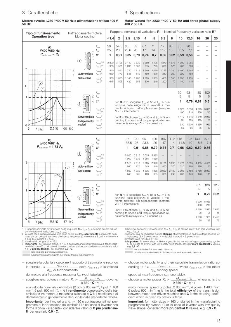
Motore avvolto 230 Y400 V 50 Hz e alimentazione trifase 400 V50 Hz.
Motor wound for 230 Y400 V 50 Hz and three-phase supply400 V 50 Hz.
Tipo di funzionamento Raffreddamento motoreOperation type Motor cooling
Rapporto nominale di variazione R1) - Nominal frequency variation ratio R1)
1,4 2 2,5 3,15 4 5 6,3 8 10 12,5 16 20 25
A)Y400 V/50 HzPa/at n max = PN
B)400 V/87 Hz
Pa/at n max = 1,73 PN
AutoventilatoSelf-cooled
ServoventilatoIndependentlycooled
AutoventilatoSelf-cooled
ServoventilatoIndependentlycooled
fmax 50 54,5 60 63 67 71 75 80 85 90 – – –fmin 35,5 28 23,6 20 17 14 11,8 10 8,5 7,1 – – –
C4) 1 0,91 0,85 0,79 0,74 0,7 0,66 0,62 0,59 0,56 – – –
nmax 22) 3) 2 820 3 105 3 440 3 630 3 880 4 125 4 370 4 675 4 980 5 285 – – –
nmin 22) 3) 1 960 1 535 1 285 1 080 915 745 620 520 435 360 – – –
nmax 42) 1 410 1 550 1 720 1 815 1 940 2 060 2 185 2 340 2 490 2 645 – – –
nmin 42) 980 770 645 540 460 370 310 260 220 180 – – –
nmax 62) 930 1 025 1 140 1 200 1 285 1 365 1 450 1 550 1 655 1 755 – – –
nmin 62) 645 505 420 355 300 240 200 170 140 115 – – –
fmax 50 63 80 100 –fmin 5 5 5 5 –
C4) 1 0,79 0,62 0,5 –
nmax 22) 3) 2 820 3 630 4 675 5 895 –
nmin 22) 3) 190 210 230 245 –
nmax 42) 1 410 1 815 2 340 2 950 –
nmin 42) 95 105 115 120 –
nmax 62) 930 1 200 1 550 1 960 –
nmin 62) 55 65 75 80 –
fmax 87 90 95 100 106 112 118 125 140 150 –fmin 35,5 28 23,6 20 17 14 11,8 10 8,5 7,1 –
C4) 1 0,91 0,85 0,79 0,74 0,7 0,66 0,62 0,59 0,56 –
nmax 22) 3) 5 020 5 215 5 525 5 835 – – – – – – –
nmin 22) 3) 1 960 1 535 1 285 1 080 – – – – – – –
nmax 42) 2 510 2 610 2 765 2 920 3 105 3 285 3 470 3 685 4 135 4 435 –
nmin 42) 980 770 645 540 460 370 310 260 220 180 –
nmax 62) 1 660 1 730 1 835 1 935 2 060 2 180 2 305 2 450 2 750 2 950 –
nmin 62) 645 505 420 355 300 240 200 170 140 115 –
Per R 10 scegliere fmax 50 e fmin 5 infunzione delle esigenze di velocità e mo-mento richiesti dall’applicazione (sempreC = 1); interpellarci.
For R 10 choose fmax 50 and fmin 5 ac-cording to speed and torque application re-quirements (always C = 1); consult us.
fmax 87 100 125fmin 5 5 5
C4) 1 0,79 0,62
nmax 22) 3) 5 020 5 835 –
nmin 22) 3) 190 210 –
nmax 42) 2 510 2 920 3 685
nmin 42) 95 105 115
nmax 62) 1 660 1 935 2 450
nmin 62) 55 65 75
Per R 16 scegliere fmax 87 e fmin 5 infunzione delle esigenze di velocità e mo-mento richiesti dall’applicazione (sempreC = 1); interpellarci.
For R 16 choose fmax 87 and fmin 5 ac-cording to speed and torque application re-quirements (always C = 1); consult us.
1) Il rapporto nominale di variazione della frequenza R = fmax / fmin è sempre minore del rap-porto effettivo di variazione (nmax / nmin).
2) Velocità reale approssimativa che tiene conto sia dello scorrimento a momento nomi-nale, sia del boost di tensione alle basse frequenze (2 = motore a 2 poli; 4 = motore a4 poli; 6 = motore a 6 poli).
3) Valori validi per grand. 132.4) Importante: per i motori grand. 160 o contrassegnati nel programma di fabbricazio-
ne dal simbolo o nel caso di inverter con forma d’onda «scadente» considerare valo-ri di C più prudenziali, per esempio 0,9 · C.
Sconsigliato per motivi economici.Normalmente sconsigliato per motivi tecnici ed economici.
1) Nominal frequency variation ratio R = fmax / fmin is always lower than real variation ratio(nmax / nmin).
2) Approx. real speed refers both to slipping at nominal torque and to voltage boost at lowfrequency (2 = 2 poles motor; 4 = 4 poles motor; 6 = 6 poles motor).
3) Values valid for sizes 132.4) Important: for motor sizes 160 or signed in the manufacturing programme by symbol
or in case of inverter with low quality wave shape, consider more prudential C values,e.g. 0,9 · C.
Not advisable for economic reasons.Usually not advisable both for technical and economic reasons.
– scegliere la polarità e calcolare il rapporto di trasmissione secondola formula i = dove nmax 2, 4, 6 è la velocità
del motore alla frequenza massima fmax (ved. tabella);
– scegliere una potenza motore PN dove nN
è la velocità nominale del motore (2 poli: 2 800 min-1; 4 poli: 1 400min-1; 6 poli: 900 min-1), è il rendimento complessivo della tra-smissione tra motore e macchina azionata e C è il coefficiente dideclassamento generalmente deducibile dalla precedente tabella.Importante: per i motori grand. 160 o contrassegnati nel pro-gramma di fabbricazione dal simbolo o nel caso di inverter conforma d’onda «scadente» considerare valori di C più prudenzia-li, per esempio 0,9 · C.
Mrichiesto · nN
9 550 · C · · i
nmax 2, 4, 6
nmax di funzionamento
– choose motor polarity and then calculate transmission ratio ac-cording to i = where nmax 2, 4, 6 is the motor
speed at max frequency fmax (see table);
– choose a motor power PN where nN is the
motor nominal speed (2 poles: 2 800 min-1; 4 poles: 1 400 min-1;6 poles: 900 min-1), is the total efficiency of the transmissionbetween motor and driven machine and C is the derating coeffi-cient which is given by previous table.Important: for motor sizes 160 or signed in the manufacturingprogramme by symbol or in case of inverter with low qualitywave shape, consider more prudential C values, e.g. 0,9 · C.
Mrequired · nN
9 550 · C · · i
nmax 2, 4, 6
nmax running speed
1
1
2
2
16
3. Caratteristiche 3. Specifications
Scelta e programmazione dell’inverterRequisiti per l’inverter: buona concezione e qualità, correntenominale adeguata, corretta impostazione della curva U/f in re-lazione alla tensione nominale del motore, «boost» di tensione noneccessivo (circa 25% 0% per 5 30 Hz), adeguata limitazionedi corrente in relazione alla corrente di targa del motore e ai sovrac-carichi ammessi/richiesti; buona messa a punto degli innumerevo-li parametri che i moderni inverter consentono di impostare per evi-tare anomalie e ottimizzare il funzionamento dell’azionamento.Grandezza inverter. È buona norma scegliere un inverter con cor-rente nominale almeno uguale a 1,12 1,25 IN motore e concapacità di sovraccarico di corrente superiore di 1,12 1,25 volteil sovraccarico di momento torcente richiesto. Normalmente, perMmax / MN = 1,5 occorre Imax / IN motore ≈ 1,7 2.
Considerazioni, indicazioni, verificheTempo di accelerazione. Verificare che il tempo di accelerazioneimpostato nell’inverter non sia inferiore a quello ottenibile con un mo-mento di avviamento pari a 1,32 1,5 MN (in relazione anche allalimitazione di corrente dell’inverter); l’impostazione di tempi inferioriporta ad una minore accelerazione e ad un aumento di correnteassorbita.Frequenza di avviamento. Data la minore corrente assorbita dalmotore nella fase di avviamento rispetto al caso di alimentazione di-retta da rete, per un tempo di avviamento massimo di 0,5 1 s, lamassima frequenza di avviamento z è almeno 180 avv./h fino allagrandezza 90, 90 avv./h per le grandezze 100 ... 132, 45 avv./h perle grandezze superiori.Per tempi di accelerazione sufficientemente lunghi, quando il mo-mento accelerante non supera MN, non è necessario verificare la fre-quenza di avviamento. Per esigenze superiori interpellarci.Sovraccarichi. Nel caso di servizi caratterizzati da sovraccarichie/o avviamenti frequenti e di lunga durata verificare l’idoneità termi-ca di inverter e motore in base alla corrente quadratica media assor-bita confrontata con un valore limite proporzionale alla correntenominale IN del motore (la costante di proporzionalità dipende daltipo di servizio e dal raffreddamento motore: interpellarci).Normalmente non è necessaria alcuna verifica se i sovraccarichinon durano più di 10 minuti ogni ora.Collegamento motore a stella (Y). Quando possibile, preferire ilcollegamento motore a stella rispetto a quello a triangolo in quantoa causa dell’assenza di correnti di circolazione interne si hanno mi-nori sovratemperature (≈ -10 °C).Frequenza portante. Valori elevati (es.: 8 16 kHz) comportano unmaggior riscaldamento sia per il motore (≈ +10 °C) sia per l’inverter,ma consentono un funzionamento completamente esente da suonifastidiosi (toni puri); per distanze tra inverter e motore superiori ai5 10 m, si aggravano le problematiche relative ai disturbi elettro-magnetici.Motore autofrenante e/o con servoventilatore. Freno e servoven-tilatore devono sempre essere alimentati direttamente da rete. Con-temporaneamente all’intervento del freno è necessario dare ilcomando di arresto all’inverter.Motore accoppiato a un riduttore. Privilegiare le velocità basse sianella scelta della polarità sia nella posizione del campo di variazio-ne per limitare rumorosità e riscaldamenti e aumentare la duratadegli anelli di tenuta.Alimentazione inverter con tensione 400 V 50/60 Hz. Verifica-ta l’idoneità dell’inverter al valore di tensione di alimentazione è pos-sibile e conveniente utilizzare il motore con avvolgimento normale230 Y400 V 50 Hz o 400 V 50 Hz (equivalente a 277 Y480 V 60Hz o 480 V 60 Hz) impostando l’inverter in modo che fornisca al mo-tore U/f costante = Utarga / ftarga. Per precauzioni aggiuntive ved. p.tosuccessivo.
Picchi di tensione (Umax), gradienti di tensione (dU/dt), lunghezza caviL’impiego di inverter richiede alcu-ne precauzioni relative ai picchi ditensione (Umax) e ai gradienti ditensione (dU/dt) che si generanocon questo tipo di alimentazione ; ivalori sono via via più elevati alcrescere della tensione di rete UNdella grandezza motore, della lun-ghezza cavi di alimentazione trainverter e motore e al peggioraredella qualità dell’inveter.Per tensioni di rete UN 400 V, pic-chi di tensione Umax 1 000 V, gra-dienti di tensione dU/dt 1 kV/s,cavi di alimentazione tra inverter emotore 30 m, si raccomanda l’im-piego di esecuzioni speciali per ilmotore (ved. tabella) e/o l’inserzionedi filtri adeguati tra inverter e motore.
Inverter selection and programmingRequisites for the inverter: good concept and quality, adequatenominal current, correct setting of U/f characteristic curve ac-cording to motor nominal voltage, not excessive voltage «boost»(about 25% 0% for 5 30 Hz), proper current limitation accord-ing to motor current (stated on the name plate) and to the admissi-ble/required overloads; good setting of the innumerable driveparameters that the new generation inverters allow to programme inorder to avoid any problems and to optimise the drive operation.Inverter size. It is recommended to choose an inverter with nomi-nal current at least equal to 1,12 1,25 IN of motor and with cur-rent overload capacity higher than 1,12 1,25 times the torqueoverload required. Usually, for Mmax / MN = 1,5, it is necessary tohave Imax / IN motor ≈ 1,7 2.
Considerations, indications, verificationsAcceleration time. Check that the acceleration time programmed inthe inverter is not less than the value that can be obtained with start-ing torque equal to 1,32 1,5 MN (also according to inverter currentlimitation); the setting of lower values causes a lower accelerationand an increase of current absorbed.Frequency of starting. Because of the smaller amount of currentabsorbed by the motor during starting (compared to direct supply),for a maximum starting time of 0,5 1 s the max frequency of start-ing z is at least 180 start/h up to size 90, 90 start/h for sizes 100 ... 132, 45 start/h for larger sizes.It is not necessary to verify frequency of starting for sufficiently longacceleration times, when accelerating torque does not exceed MN.Consult us for higher requirements.Overloads. In the case of duty featuring frequent and long lastingoverloads and/or startings check the thermal suitability of inverterand motor according to the average quadratic current absorbedwhich should be compared to a limit value proportional to the motornominal current IN (the constant of proportionality depends on motorduty and cooling: consult us).In normal conditions it is not necessary to make any kind of verifi-cation if overloads are present for less than 10 minutes per hour.Star connection of motor (Y).Whenever possible, due to the absence of internal circulation cur-rents, the star connection of motor is to be preferred to the delta one,since the overtemperatures are lower (≈ -10 °C).Chopper frequency. High values (e.g.: 8 16 kHz) cause a high-er heating both for motor (≈ +10 °C) and for inverter but allow acompletely noise-free running (pure tones); at the same time thereis a worsening of the problems related to the electromagnetic noises, especially in case of long distances between inverter andmotor ( 5 10 m).Brake motor and/or with independent cooling fan. Brake and in-dependent cooling fan must always be directly supplied from mains.When braking it is necessary to give the all-off controller to theinverter.Motor coupled with gear reducer. Prefer the low speed in thechoice both of polarity and of position of variation range in order tolimit noise level and heating and to increase the life of oil seal rings.Inverter supply with voltage 400 V 50/60 Hz. After having veri-fied the suitability of inverter to the supply voltage value, it is possi-ble and convenient to use the motor with standard winding 230Y400 V 50 Hz or 400 V 50 Hz (equivalent to 277 Y480 V 60 Hz or480 V 60 Hz) by setting the inverter so that it provides to the motora constant U/f = Uname plate / fname plate. For additional precautions see fol-lowing point.
Voltage peaks (Umax), voltage gradients (dU/dt), cable lengthThe use of inverters requires someprecautions relevant to voltagepeaks (Umax) and voltage gra-dients (dU/dt) generated by thispower supply type; the valuesbecome higher by increasing themains voltage UN the motor size,the power supply cable length bet-ween inverter and motor and byworsening the inverter quality.For main voltages UN 400, volta-ges peaks Umax 1 000 V, voltagegradients dU/dt 1 kV/s, supplycable between inverter and motor 30 m, it is recommended to usenon-standard motor design (seetable) and/or adequate filters bet-ween inverter and motor.
Grand. Esecuzioni speciali per alimentazione da invertermotore Non-standard designs for supply from inverter
Motor size UN
400 V 401 ÷ 499V 500 ÷ 690V
163 ... 160S 1(9)1) 1(9)2) 1(9)3) + filtro/filter4)
160 ... 200 1(9)1) (51)2) (51)3) + filtro/filter4)
1) Esecuzione (ved. cap. 7) consigliabile con l’aggravarsi delle condizioni di alimentazione.2) Esecuzione (ved. cap. 7) necessaria in presenza di condizioni critiche di alimentazione.3) Esecuzione (ved. cap. 7) necessaria.4) A cura dell’Acquirente.1) Design (see ch. 7) advisable by worsening the supply conditions.2) Design (see ch. 7) necessary in presence of critical supply conditions.3) Necessary design (see ch. 7).4) On customer’s care.
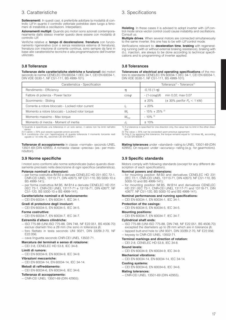
17
3. Caratteristiche 3. Specifications
3.8 TolleranzeTolleranze delle caratteristiche elettriche e funzionali dei motorisecondo le norme CENELEC EN 60034-1 (IEC 34-1, CEI EN 60034-1,DIN VDE 0530-1, NF C51-111, BS 4999-101).
3.8 TolerancesTolerances of electrical and operating specifications of the mo-tors to standards CENELEC EN 60034-1 (IEC 34-1, CEI EN 60034-1,DIN VDE 0530-1, NF C51-111, BS 4999-101).
Caratteristica - Specification Tolleranza1) - Tolerance1)
Rendimento - Efficiency -0,15 (1-)
Fattore di potenza - Power factor cos - (1-cos)/6 min 0,02, max 0,07
Scorrimento - Sliding ± 20% (± 30% per/for PN 1 kW)
Corrente a rotore bloccato - Locked rotor current IS + 20%
Momento a rotore bloccato - Locked rotor torque MS - 15% + 25% 2)
Momento massimo - Max torque Mmax - 10% 3)
Momento di inerzia - Moment of inertia J0 ± 10%1) Quando è specificata una tolleranza in un solo senso, il valore non ha limiti nell’altro
senso.2) Il valore + 25% può essere superato previo accordo.3) A condizione che con l’applicazione di questa tolleranza il momento torcente resti
uguale a 1,6 volte MN, secondo CEI EN 60034-1.
1) If a tolerance is specified for one direction only, the value has no limit in the other direc-tion.
2) The value + 25% can be exceeded upon previous agreement.3) Only if, by applying this tolerance, the torque remains equal to 1,6 times MN, according
to CEI EN 60034-1.
Tolleranze di accoppiamento in classe «normale» secondo UNEL13501-69 (DIN 42955). A richiesta: classe «precisa» (es.: per moto-riduttori).
3.9 Norme specificheI motori sono conformi alle norme sottoindicate (salvo quando diver-samente precisato nella descrizione di ogni specifica caratteristica).Potenze nominali e dimensioni:– per forma costruttiva IM B3 e derivate CENELEC HD 231 (IEC 72-1,
CNR-CEI UNEL 13113-71, DIN 42673, NF C51-110, BS 5000-10 eBS 4999-141);
– per forma costruttiva IM B5, IM B14 e derivate CENELEC HD 231(IEC 72-1, CNR-CEI UNEL 13117-71 e 13118-71, DIN 42677, NFC51-120, BS 5000-10 e BS 4999-141).
Caratteristiche nominali e di funzionamento:– CEI EN 60034-1, EN 60034-1, IEC 34-1.Gradi di protezione degli involucri:– CEI EN 60034-5, EN 60034-5, IEC 34-5.Forme costruttive:– CEI EN 60034-7, EN 60034-7, IEC 34-7.Estremità d’albero cilindriche:– ISO 775-88 (UNI-ISO 775-88, DIN 748, NF E22.051, BS 4506-70)
esclusi diametri fino a 28 mm che sono in tolleranza j6;– foro filettato in testa secondo UNI 9321, DIN 332BI.2-70, NF
E22.056;– cava linguetta secondo CNR-CEI UNEL 13502-71.Marcatura dei terminali e senso di rotazione:– CEI 2-8, CENELEC HD 53.8, IEC 34-8.Limiti di rumore:– CEI EN 60034-9, EN 60034-9, IEC 34-9.Vibrazioni meccaniche:– CEI EN 60034-14, EN 60034-14, IEC 34-14.Metodi di raffreddamento:– CEI EN 60034-6, EN 60034-6, IEC 34-6.Tolleranza di accoppiamento:– CNR-CEI UNEL 13501-69 (DIN 42955).
Mating tolerances under «standard» rating to UNEL 13501-69 (DIN42955). On request: under «accuracy» rating (e.g.: for gearmotors).
3.9 Specific standardsMotors comply with following standards (except for any different de-scription of each specification).Nominal powers and dimensions:– for mounting position IM B3 and derivatives CENELEC HD 231
(IEC 72-1, CNR-CEI UNEL 13113-71, DIN 42673, NF C51-110, BS5000-10 and BS 4999-141);
– for mounting position IM B5, IM B14 and derivatives CENELECHD 231 (IEC 72-1, CNR-CEI UNEL 13117-71 and 13118-71, DIN42677, NF C51-120, BS 5000-10 and BS 4999-141).
Nominal performances and running specifications:– CEI EN 60034-1, EN 60034-1, IEC 34-1.Protection of the casings:– CEI EN 60034-5, EN 60034-5, IEC 34-5.Mounting positions:– CEI EN 60034-7, EN 60034-7, IEC 34-7.Cylindrical shaft ends:– ISO 775-88 (UNI-ISO 775-88, DIN 748, NF E22.051, BS 4506-70)
excepted the diameters up to 28 mm which are in tolerance j6;– tapped butt-end hole to UNI 9321, DIN 332BI.2-70, NF E22.056;– keyway to CNR-CEI UNEL 13502-71.Terminal markings and direction of rotation:– CEI 2-8, CENELEC HD 53.8, IEC 34-8.Sound levels:– CEI EN 60034-9, EN 60034-9, IEC 34-9.Mechanical vibrations:– CEI EN 60034-14, EN 60034-14, IEC 34-14.Cooling systems:– CEI EN 60034-6, EN 60034-6, IEC 34-6.Mating tolerances:– CNR-CEI UNEL 13501-69 (DIN 42955).
Sollevamenti. In questi casi, è preferibile adottare la modalità di con-trollo U/f in quanto il controllo vettoriale potrebbe dare luogo a feno-meni di instabilità e oscillazioni. Interpellarci.Azionamenti multipli. Quando più motori sono azionati contempora-neamente dallo stesso inverter questo deve essere con modalità dicontrollo U/f.Verifiche relative a: tempo di decelerazione, frenatura con funzio-namento rigenerativo (con o senza resistenza esterna di frenatura),frenatura con iniezione di corrente continua, sono sempre da farsi inbase alle caratteristiche tecniche e alla programmazione dell’inverterutilizzato.
Hoisting. In these cases it is advised to adopt inverter with U/f con-trol mode since vector control could cause instability and oscillations.Consult us.Multiple drives. When several motors are connected simultaneouslyto the same inverter, this one has to be with U/f control mode.Verifications relevant to: deceleration time, braking with regenerat-ing running (with or without external braking resistance), braking withd.c. injection, are always to be done according to technical specifi-cations and to programming of inverter applied.
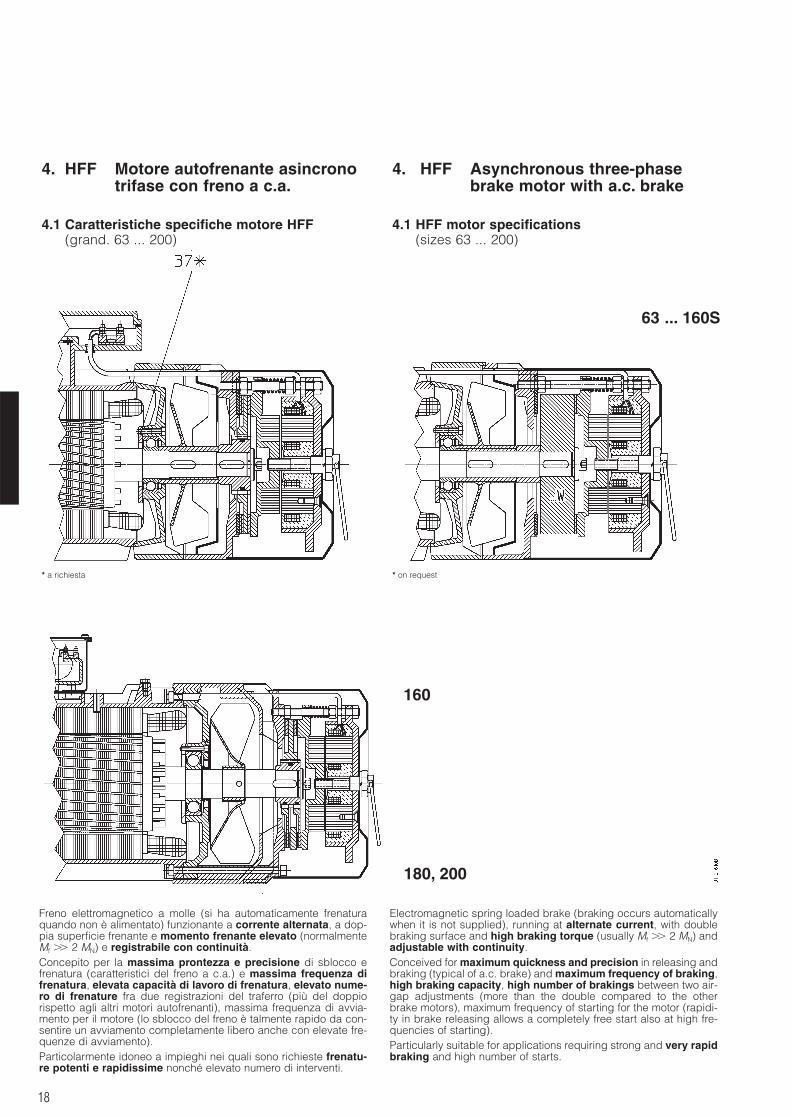
18
4. HFF Motore autofrenante asincronotrifase con freno a c.a.
4. HFF Asynchronous three-phasebrake motor with a.c. brake
4.1 Caratteristiche specifiche motore HFF(grand. 63 ... 200)
4.1 HFF motor specifications(sizes 63 ... 200)
* a richiesta * on request
Freno elettromagnetico a molle (si ha automaticamente frenaturaquando non è alimentato) funzionante a corrente alternata, a dop-pia superficie frenante e momento frenante elevato (normalmenteMf 2 MN) e registrabile con continuità.Concepito per la massima prontezza e precisione di sblocco efrenatura (caratteristici del freno a c.a.) e massima frequenza difrenatura, elevata capacità di lavoro di frenatura, elevato nume-ro di frenature fra due registrazioni del traferro (più del doppiorispetto agli altri motori autofrenanti), massima frequenza di avvia-mento per il motore (lo sblocco del freno è talmente rapido da con-sentire un avviamento completamente libero anche con elevate fre-quenze di avviamento).Particolarmente idoneo a impieghi nei quali sono richieste frenatu-re potenti e rapidissime nonché elevato numero di interventi.
Electromagnetic spring loaded brake (braking occurs automaticallywhen it is not supplied), running at alternate current, with doublebraking surface and high braking torque (usually Mf 2 MN) andadjustable with continuity.Conceived for maximum quickness and precision in releasing andbraking (typical of a.c. brake) and maximum frequency of braking,high braking capacity, high number of brakings between two air-gap adjustments (more than the double compared to the otherbrake motors), maximum frequency of starting for the motor (rapidi-ty in brake releasing allows a completely free start also at high fre-quencies of starting).Particularly suitable for applications requiring strong and very rapidbraking and high number of starts.
63 ... 160S
160
180, 200
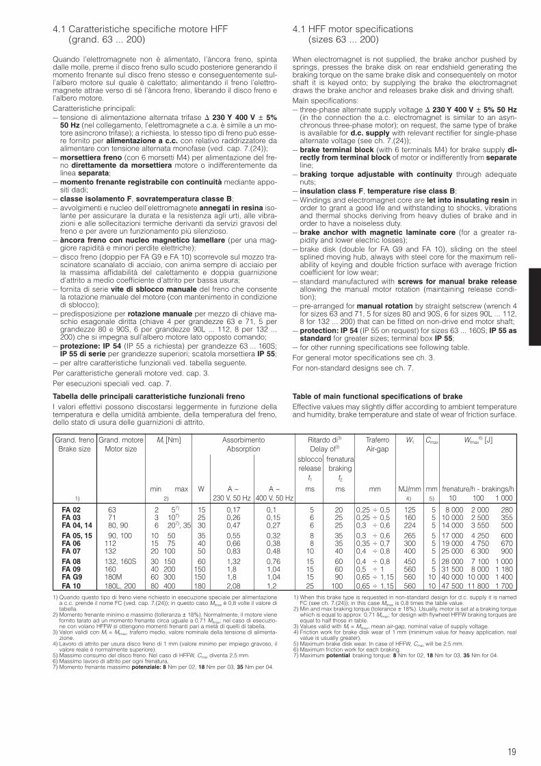
19
4.1 Caratteristiche specifiche motore HFF(grand. 63 ... 200)
4.1 HFF motor specifications(sizes 63 ... 200)
Quando l’elettromagnete non è alimentato, l’àncora freno, spintadalle molle, preme il disco freno sullo scudo posteriore generando ilmomento frenante sul disco freno stesso e conseguentemente sul-l’albero motore sul quale è calettato; alimentando il freno l’elettro-magnete attrae verso di sé l’àncora freno, liberando il disco freno el’albero motore.Caratteristiche principali:– tensione di alimentazione alternata trifase 230 Y 400 V ± 5%
50 Hz (nel collegamento, l’elettromagnete a c.a. è simile a un mo-tore asincrono trifase); a richiesta, lo stesso tipo di freno può esse-re fornito per alimentazione a c.c. con relativo raddrizzatore daalimentare con tensione alternata monofase (ved. cap. 7.(24));
– morsettiera freno (con 6 morsetti M4) per alimentazione del fre-no direttamente da morsettiera motore o indifferentemente dalinea separata;
– momento frenante registrabile con continuità mediante appo-siti dadi;
– classe isolamento F, sovratemperatura classe B;– avvolgimenti e nucleo dell’elettromagnete annegati in resina iso-
lante per assicurare la durata e la resistenza agli urti, alle vibra-zioni e alle sollecitazioni termiche derivanti da servizi gravosi delfreno e per avere un funzionamento più silenzioso.
– àncora freno con nucleo magnetico lamellare (per una mag-giore rapidità e minori perdite elettriche);
– disco freno (doppio per FA G9 e FA 10) scorrevole sul mozzo tra-scinatore scanalato di acciaio, con anima sempre di acciaio perla massima affidabilità del calettamento e doppia guarnizioned’attrito a medio coefficiente d’attrito per bassa usura;
– fornita di serie vite di sblocco manuale del freno che consentela rotazione manuale del motore (con mantenimento in condizionedi sblocco);
– predisposizione per rotazione manuale per mezzo di chiave ma-schio esagonale diritta (chiave 4 per grandezze 63 e 71, 5 pergrandezze 80 e 90S, 6 per grandezze 90L ... 112, 8 per 132 ...200) che si impegna sull’albero motore lato opposto comando;
– protezione: IP 54 (IP 55 a richiesta) per grandezze 63 ... 160S;IP 55 di serie per grandezze superiori; scatola morsettiera IP 55;
– per altre caratteristiche funzionali ved. tabella seguente.Per caratteristiche generali motore ved. cap. 3.Per esecuzioni speciali ved. cap. 7.
Tabella delle principali caratteristiche funzionali frenoI valori effettivi possono discostarsi leggermente in funzione dellatemperatura e della umidità ambiente, della temperatura del freno,dello stato di usura delle guarnizioni di attrito.
When electromagnet is not supplied, the brake anchor pushed bysprings, presses the brake disk on rear endshield generating thebraking torque on the same brake disk and consequentely on motorshaft it is keyed onto; by supplying the brake the electromagnetdraws the brake anchor and releases brake disk and driving shaft.Main specifications:– three-phase alternate supply voltage 230 Y 400 V ± 5% 50 Hz
(in the connection the a.c. electromagnet is similar to an asyn-chronous three-phase motor); on request, the same type of brakeis available for d.c. supply with relevant rectifier for single-phasealternate voltage (see ch. 7.(24));
– brake terminal block (with 6 terminals M4) for brake supply di-rectly from terminal block of motor or indifferently from separateline;
– braking torque adjustable with continuity through adequatenuts;
– insulation class F, temperature rise class B;– Windings and electromagnet core are let into insulating resin in
order to grant a good life and withstanding to shocks, vibrationsand thermal shocks deriving from heavy duties of brake and inorder to have a noiseless duty.
– brake anchor with magnetic laminate core (for a greater ra-pidity and lower electric losses);
– brake disk (double for FA G9 and FA 10), sliding on the steelsplined moving hub, always with steel core for the maximum reli-ability of keying and double friction surface with average frictioncoefficient for low wear;
– standard manufactured with screws for manual brake releaseallowing the manual motor rotation (maintaining release condi-tion);
– pre-arranged for manual rotation by straight setscrew (wrench 4for sizes 63 and 71, 5 for sizes 80 and 90S, 6 for sizes 90L ... 112,8 for 132 ... 200) that can be fitted on non-drive end motor shaft;
– protection: IP 54 (IP 55 on request) for sizes 63 ... 160S; IP 55 asstandard for greater sizes; terminal box IP 55;
– for other running specifications see following table.For general motor specifications see ch. 3.For non-standard designs see ch. 7.
Table of main functional specifications of brakeEffective values may slightly differ according to ambient temperatureand humidity, brake temperature and state of wear of friction surface.
Grand. freno Grand. motore Mf [Nm] Assorbimento Ritardo di3) Traferro W1 Cmax Wfmax6) [J]
Brake size Motor size Absorption Delay of3) Air-gapsblocco frenaturarelease braking
t1 t2min max W A ~ A ~ ms ms mm MJ/mm mm frenature/h - brakings/h
1) 2) 230 V, 50 Hz 400 V, 50 Hz 4) 5) 10 100 1 000
FA 02 63 2 57) 15 0,17 0,1 5 20 0,25 0,55 125 5 8 000 2 000 280FA 03 71 3 107) 25 0,26 0,15 6 25 0,25 0,55 160 5 10 000 2 500 355FA 04, 14 80, 90 6 207), 35 30 0,47 0,27 6 25 0,3 0,65 224 5 14 000 3 550 500FA 05, 15 90, 100 10 50 35 0,55 0,32 8 35 0,3 0,65 265 5 17 000 4 250 600FA 06 112 15 75 40 0,66 0,38 8 35 0,35 0,75 300 5 19 000 4 750 670FA 07 132 20 100 50 0,83 0,48 10 40 0,4 0,85 400 5 25 000 6 300 900FA 08 132, 160S 30 150 60 1,32 0,76 15 60 0,4 0,85 450 5 28 000 7 100 1 000FA 09 160 40 200 150 1,8 1,04 15 60 0,5 1,15 560 5 31 500 8 000 1 180FA G9 180M 60 300 150 1,89 1,04 15 90 0,65 1,15 560 10 40 000 10 000 1 400FA 10 180L, 200 80 400 180 2,08 1,21 25 100 0,65 1,15 560 10 47 500 11 800 1 700
1) Quando questo tipo di freno viene richiesto in esecuzione speciale per alimentazionea c.c. prende il nome FC (ved. cap. 7.(24)); in questo caso Mfmax è 0,8 volte il valore ditabella.
2) Momento frenante minimo e massimo (tolleranza ± 18%). Normalmente, il motore vienefornito tarato ad un momento frenante circa uguale a 0,71 Mfmax; nel caso di esecuzio-ne con volano HFFW si ottengono momenti frenanti pari a metà di quelli di tabella.
3) Valori validi con Mf = Mfmax, traferro medio, valore nominale della tensione di alimenta-zione.
4) Lavoro di attrito per usura disco freno di 1 mm (valore minimo per impiego gravoso, ilvalore reale è normalmente superiore).
5) Massimo consumo del disco freno. Nel caso di HFFW, Cmax diventa 2,5 mm.6) Massimo lavoro di attrito per ogni frenatura.7) Momento frenante massimo potenziale: 8 Nm per 02, 18 Nm per 03, 35 Nm per 04.
1) When this brake type is requested in non-standard design for d.c. supply it is namedFC (see ch. 7.(24)); in this case Mfmax is 0,8 times the table value.
2) Min and max braking torque (tolerance ± 18%). Usually, motor is set at a braking torquewhich is equal to approx. 0,71 Mfmax; for design with flywheel HFFW braking torques areequal to half those in table.
3) Values valid with Mf = Mfmax, mean air-gap, nominal value of supply voltage.4) Friction work for brake disk wear of 1 mm (minimum value for heavy application, real
value is usually greater).5) Maximum brake disk wear. In case of HFFW, Cmax will be 2,5 mm.6) Maximum friction work for each braking.7) Maximum potential braking torque: 8 Nm for 02, 18 Nm for 03, 35 Nm for 04.
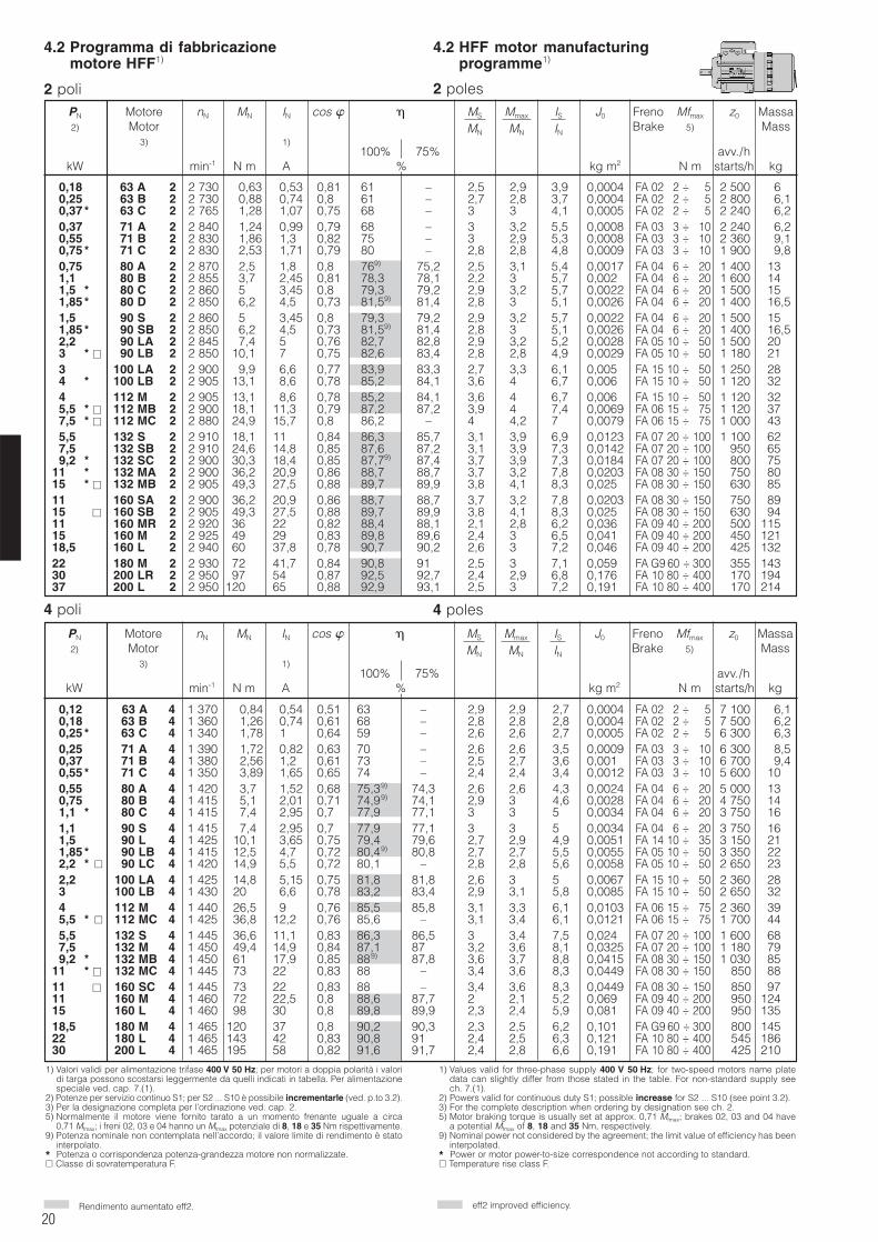
20
4.2 Programma di fabbricazionemotore HFF1)
4.2 HFF motor manufacturingprogramme1)
2 poli 2 poles
Rendimento aumentato eff2. eff2 improved efficiency.
4 poles4 poli
1) Valori validi per alimentazione trifase 400 V 50 Hz; per motori a doppia polarità i valoridi targa possono scostarsi leggermente da quelli indicati in tabella. Per alimentazionespeciale ved. cap. 7.(1).
2) Potenze per servizio continuo S1; per S2 ... S10 è possibile incrementarle (ved. p.to 3.2).3) Per la designazione completa per l’ordinazione ved. cap. 2.5) Normalmente il motore viene fornito tarato a un momento frenante uguale a circa
0,71 Mfmax; i freni 02, 03 e 04 hanno un Mfmax potenziale di 8, 18 e 35 Nm rispettivamente.9) Potenza nominale non contemplata nell’accordo; il valore limite di rendimento è stato
interpolato.* Potenza o corrispondenza potenza-grandezza motore non normalizzate. Classe di sovratemperatura F.
1) Values valid for three-phase supply 400 V 50 Hz; for two-speed motors name platedata can slightly differ from those stated in the table. For non-standard supply seech. 7.(1).
2) Powers valid for continuous duty S1; possible increase for S2 ... S10 (see point 3.2).3) For the complete description when ordering by designation see ch. 2.5) Motor braking torque is usually set at approx. 0,71 Mfmax; brakes 02, 03 and 04 have
a potential Mfmax of 8, 18 and 35 Nm, respectively.9) Nominal power not considered by the agreement; the limit value of efficiency has been
interpolated.* Power or motor power-to-size correspondence not according to standard. Temperature rise class F.
0,18 63 A 2 2 730 0,63 0,53 0,81 61 – 2,5 2,9 3,9 0,0004 FA 02 02 ÷ 005 2 500 60,25 63 B 2 2 730 0,88 0,74 0,8 61 – 2,7 2,8 3,7 0,0004 FA 02 02 ÷ 005 2 800 6,10,37 * 63 C 2 2 765 1,28 1,07 0,75 68 – 3 3 4,1 0,0005 FA 02 02 ÷ 005 2 240 6,20,37 71 A 2 2 840 1,24 0,99 0,79 68 – 3 3,2 5,5 0,0008 FA 03 03 ÷ 010 2 240 6,20,55 71 B 2 2 830 1,86 1,3 0,82 75 – 3 2,9 5,3 0,0008 FA 03 03 ÷ 010 2 360 9,10,75 * 71 C 2 2 830 2,53 1,71 0,79 80 – 2,8 2,8 4,8 0,0009 FA 03 03 ÷ 010 1 900 9,80,75 80 A 2 2 870 2,5 1,8 0,81 769) 75,2 2,5 3,1 5,4 0,0017 FA 04 06 ÷ 020 1 400 131,1 80 B 2 2 855 3,7 2,45 0,81 78,3 78,1 2,2 3 5,7 0,002 FA 04 06 ÷ 020 1 600 141,5 * 80 C 2 2 860 5 3,45 0,8 79,3 79,2 2,9 3,2 5,7 0,0022 FA 04 06 ÷ 020 1 500 151,85 * 80 D 2 2 850 6,2 4,5 0,73 81,59) 81,4 2,8 3 5,1 0,0026 FA 04 06 ÷ 020 1 400 16,51,5 90 S 2 2 860 5 3,45 0,8 79,3 79,2 2,9 3,2 5,7 0,0022 FA 04 06 ÷ 020 1 500 151,85 * 90 SB 2 2 850 6,2 4,5 0,73 81,59) 81,4 2,8 3 5,1 0,0026 FA 04 06 ÷ 020 1 400 16,52,2 90 LA 2 2 845 7,4 5 0,76 82,7 82,8 2,9 3,2 5,2 0,0028 FA 05 10 ÷ 050 1 500 203 * 90 LB 2 2 850 10,1 7 0,75 82,6 83,4 2,8 2,8 4,9 0,0029 FA 05 10 ÷ 050 1 180 213 100 LA 2 2 900 9,9 6,6 0,77 83,9 83,3 2,7 3,3 6,1 0,005 FA 15 10 ÷ 050 1 250 284 * 100 LB 2 2 905 13,1 8,6 0,78 85,2 84,1 3,6 4 6,7 0,006 FA 15 10 ÷ 050 1 120 324 * 112 M 2 2 905 13,1 8,6 0,78 85,2 84,1 3,6 4 6,7 0,006 FA 15 10 ÷ 050 1 120 325,5 * 112 MB 2 2 900 18,1 11,3 0,79 87,2 87,2 3,9 4 7,4 0,0069 FA 06 15 ÷ 075 1 120 377,5 * 112 MC 2 2 880 24,9 15,7 0,80 86,2 – 4 4,2 7 0,0079 FA 06 15 ÷ 075 1 000 435,5 132 S 2 2 910 18,1 11 0,84 86,3 85,7 3,1 3,9 6,9 0,0123 FA 07 20 ÷ 100 1 100 627,5 132 SB 2 2 910 24,6 14,8 0,85 87,6 87,2 3,1 3,9 7,3 0,0142 FA 07 20 ÷ 100 1 950 659,2 * 132 SC 2 2 900 30,3 18,4 0,85 87,79) 87,4 3,7 3,9 7,3 0,0184 FA 07 20 ÷ 100 1 800 75
11 * 132 MA 2 2 900 36,2 20,9 0,86 88,7 88,7 3,7 3,2 7,8 0,0203 FA 08 30 ÷ 150 1 750 8015 * 132 MB 2 2 905 49,3 27,5 0,88 89,7 89,9 3,8 4,1 8,3 0,025 FA 08 30 ÷ 150 1 630 8511 * 160 SA 2 2 900 36,2 20,9 0,86 88,7 88,7 3,7 3,2 7,8 0,0203 FA 08 30 ÷ 150 1 750 8915 160 SB 2 2 905 49,3 27,5 0,88 89,7 89,9 3,8 4,1 8,3 0,025 FA 08 30 ÷ 150 1 630 9411 160 MR 2 2 920 36 22 0,82 88,4 88,1 2,1 2,8 6,2 0,036 FA 09 40 ÷ 200 1 500 11515 160 M 2 2 925 49 29 0,83 89,8 89,6 2,4 3 6,5 0,041 FA 09 40 ÷ 200 1 450 12118,5 160 L 2 2 940 60 37,8 0,78 90,7 90,2 2,6 3 7,2 0,046 FA 09 40 ÷ 200 1 425 13222 180 M 2 2 930 72 41,7 0,84 90,8 91,0 2,5 3 7,1 0,059 FA G9 60 ÷ 300 1 355 14330 200 LR 2 2 950 97 54 0,87 92,5 92,7 2,4 2,9 6,8 0,176 FA 10 80 ÷ 400 1 170 19437 200 L 2 2 950 120 65 0,88 92,9 93,1 2,5 3 7,2 0,191 FA 10 80 ÷ 400 1 170 214
0,12 63 A 4 1 370 0,84 0,54 0,51 63 – 2,9 2,9 2,7 0,0004 FA 02 02 ÷ 005 7 100 6,10,18 63 B 4 1 360 1,26 0,74 0,61 68 – 2,8 2,8 2,8 0,0004 FA 02 02 ÷ 005 7 500 6,20,25 * 63 C 4 1 340 1,78 1 0,64 59 – 2,6 2,6 2,7 0,0005 FA 02 02 ÷ 005 6 300 6,30,25 71 A 4 1 390 1,72 0,82 0,63 70 – 2,6 2,6 3,5 0,0009 FA 03 03 ÷ 010 6 300 8,50,37 71 B 4 1 380 2,56 1,2 0,61 73 – 2,5 2,7 3,6 0,001 FA 03 03 ÷ 010 6 700 9,40,55 * 71 C 4 1 350 3,89 1,65 0,65 74 – 2,4 2,4 3,4 0,0012 FA 03 03 ÷ 010 5 600 100,55 80 A 4 1 420 3,7 1,52 0,68 75,39) 74,3 2,6 2,6 4,3 0,0024 FA 04 06 ÷ 020 5 000 130,75 80 B 4 1 415 5,1 2,01 0,71 74,99) 74,1 2,9 3 4,6 0,0028 FA 04 06 ÷ 020 4 750 141,1 * 80 C 4 1 415 7,4 2,95 0,7 77,9 77,1 3 3 5 0,0034 FA 04 06 ÷ 020 3 750 161,1 90 S 4 1 415 7,4 2,95 0,7 77,9 77,1 3 3 5 0,0034 FA 04 06 ÷ 020 3 750 161,5 90 L 4 1 425 10,1 3,65 0,75 79,4 79,6 2,7 2,9 4,9 0,0051 FA 14 10 ÷ 035 3 150 211,85 * 90 LB 4 1 415 12,5 4,7 0,72 80,49) 80,8 2,7 2,7 5,5 0,0055 FA 05 10 ÷ 050 3 350 222,2 * 90 LC 4 1 420 14,9 5,5 0,72 80,1 – 2,8 2,8 5,6 0,0058 FA 05 10 ÷ 050 2 650 232,2 100 LA 4 1 425 14,8 5,15 0,75 81,8 81,8 2,6 3 5 0,0067 FA 15 10 ÷ 050 2 360 283 100 LB 4 1 430 20 6,6 0,78 83,2 83,4 2,9 3,1 5,8 0,0085 FA 15 10 ÷ 050 2 650 324 112 M 4 1 440 26,5 9 0,76 85,5 85,8 3,1 3,3 6,1 0,0103 FA 06 15 ÷ 075 2 360 395,5 * 112 MC 4 1 425 36,8 12,2 0,76 85,6 – 3,1 3,4 6,1 0,0121 FA 06 15 ÷ 075 1 700 445,5 132 S 4 1 445 36,6 11,1 0,83 86,3 86,5 3,3 3,4 7,5 0,024 FA 07 20 ÷ 100 1 600 687,5 132 M 4 1 450 49,4 14,9 0,84 87,1 87,5 3,2 3,6 8,1 0,0325 FA 07 20 ÷ 100 1 180 799,2 * 132 MB 4 1 450 61 17,9 0,85 889) 87,8 3,6 3,7 8,8 0,0415 FA 08 30 ÷ 150 1 030 85
11 * 132 MC 4 1 445 73 22 0,83 88 – 3,4 3,6 8,3 0,0449 FA 08 30 ÷ 150 850 8811 160 SC 4 1 445 73 22 0,83 88 – 3,4 3,6 8,3 0,0449 FA 08 30 ÷ 150 850 9711 160 M 4 1 460 72 22,5 0,8 88,6 87,7 2 2,1 5,2 0,069 FA 09 40 ÷ 200 950 12415 160 L 4 1 460 98 30 0,8 89,8 89,9 2,3 2,4 5,9 0,081 FA 09 40 ÷ 200 950 13518,5 180 M 4 1 465 120 37 0,8 90,2 90,3 2,3 2,5 6,2 0,101 FA G9 60 ÷ 300 800 14522 180 L 4 1 465 143 42 0,83 90,8 91,0 2,4 2,5 6,3 0,121 FA 10 80 ÷ 400 545 18630 200 L 4 1 465 195 58 0,82 91,6 91,7 2,4 2,8 6,6 0,191 FA 10 80 ÷ 400 425 210
PN Motore nN MN IN cos MS Mmax IS J0 Freno Mfmax z0 Massa2) Motor MN MN IN Brake 5) Mass
3) 1)100% 75% avv./h
kW min-1 N m A % kg m2 N m starts/h kg
PN Motore nN MN IN cos MS Mmax IS J0 Freno Mfmax z0 Massa2) Motor MN MN IN Brake 5) Mass
3) 1)100% 75% avv./h
kW min-1 N m A % kg m2 N m starts/h kg
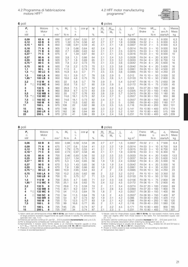
21
4.2 Programma di fabbricazionemotore HFF1)
4.2 HFF motor manufacturingprogramme1)
6 poli 6 poles
8 poli 8 poles
1) Valori validi per alimentazione trifase 400 V 50 Hz; per motori a doppia polarità i valoridi targa possono scostarsi leggermente da quelli indicati in tabella. Per alimentazionespeciale ved. cap. 7.(1).
2) Potenze per servizio continuo S1; per S2 ... S10 è possibile incrementarle (ved. p.to 3.2).3) Per la designazione completa per l’ordinazione ved. cap. 2.5) Normalmente il motore viene fornito tarato a un momento frenante uguale a circa
0,71 Mfmax; i freni 02, 03 e 04 hanno un Mfmax potenziale di 8, 18 e 35 Nm rispettivamente.* Potenza o corrispondenza potenza-grandezza motore non normalizzate. Classe di sovratemperatura F.
1) Values valid for three-phase supply 400 V 50 Hz; for two-speed motors name platedata can slightly differ from those stated in the table. For non-standard supply seech. 7.(1).
2) Powers valid for continuous duty S1; possible increase for S2 ... S10 (see point 3.2).3) For the complete description when ordering by designation see ch. 2.5) Motor braking torque is usually set at approx. 0,71 Mfmax; brakes 02, 03 and 04 have a
potential Mfmax of 8, 18 and 35 Nm, respectively.* Power or motor power-to-size correspondence not according to standard. Temperature rise class F.
PN Motore nN MN IN cos MS Mmax IS J0 Freno Mfmax z0 Massa2) Motor 1) MN MN IN Brake 5) avv./h Mass
kW 3) min-1 N m A % kg m2 N m starts/h kg
0,09 63 A 6 890 0,97 0,64 0,55 37 2,7 2,7 1,8 0,0006 FA 02 2 5 8 000 6,30,12 63 B 6 870 1,32 0,74 0,56 42 2,7 2,7 1,8 0,0006 FA 02 2 5 8 000 6,30,15 * 63 C 6 850 1,68 0,81 0,59 45 2,1 2,1 1,8 0,0007 FA 02 2 5 8 000 6,40,18 71 A 6 905 1,9 0,66 0,64 62 2,4 2,4 3 0,0014 FA 03 3 10 9 000 9,80,25 71 B 6 890 2,7 0,89 0,63 64 2,1 2,1 2,5 0,0015 FA 03 3 10 8 500 9,80,37 * 71 C 6 875 4 1,34 0,67 60 2,1 2,1 2,5 0,0016 FA 03 3 10 8 000 100,37 80 A 6 930 3,8 1,3 0,66 64 2,1 2,4 3,3 0,0028 FA 04 6 20 6 300 130,55 80 B 6 920 5,7 1,8 0,69 65 2,1 2,3 3,2 0,0033 FA 04 6 20 6 700 140,75 * 80 C 6 920 7,8 2,2 0,73 70 2,1 2,3 3,6 0,0042 FA 04 6 20 5 600 160,75 90 S 6 920 7,8 2,2 0,73 70 2,1 2,3 3,6 0,0042 FA 04 6 20 5 600 161,1 90 L 6 915 11,5 3 0,74 70 2,3 2,3 3,9 0,0061 FA 05 10 50 4 500 221,5 * 90 LC 6 905 15,8 4,3 0,7 71 2,5 2,5 3,6 0,0065 FA 05 10 50 4 250 231,5 100 LA 6 950 15,1 3,9 0,7 78 2,6 2,9 5 0,012 FA 15 10 50 3 000 321,85 * 100 LB 6 950 18,6 4,6 0,75 78 2,5 2,6 5,1 0,0133 FA 15 10 50 2 800 352,2 112 M 6 955 22 5,8 0,7 79 2,9 3 5,4 0,0147 FA 06 15 75 2 650 393 * 112 MC 6 940 30,6 7,6 0,7 80 2,9 2,9 5 0,0172 FA 06 15 75 2 500 453 132 S 6 960 29,8 7,5 0,71 82 2,3 2,8 5,4 0,024 FA 07 20 100 2 120 664 132 M 6 960 39,8 9,7 0,72 83 2,9 3,3 6,2 0,0325 FA 07 20 100 1 400 745,5 132 MB 6 950 55 12,7 0,76 83 2,6 2,9 5,7 0,0415 FA 08 30 150 1 180 857,5 * 132 MC 6 960 74,6 18,1 0,73 82 2,4 2,7 5 0,0557 FA 08 30 150 950 887,5 160 SC 6 960 74,6 18,1 0,73 82 2,4 2,7 5 0,0557 FA 08 30 150 950 977,5 160 M 6 965 74 15,5 0,82 85 2 2,3 5 0,093 FA 09 40 200 1180 117
11 160 L 6 970 108 22 0,82 88 2,3 2,5 5,5 0,116 FA 09 40 200 950 13115 180 L 6 970 148 30 0,82 88 2,3 2,2 5,2 0,141 FA 10 80 400 670 17418,5 200 LR 6 970 182 36 0,84 89 2,1 2,3 5,2 0,181 FA 10 80 400 515 18922 200 L 6 970 216 41 0,86 89 2,4 2,4 5,6 0,231 FA 10 80 400 425 209
PN Motore nN MN IN cos MS Mmax IS J0 Freno Mfmax z0 Massa2) Motor 1) MN MN IN Brake 5) avv./h Mass
kW 3) min-1 N m A % kg m2 N m starts/h kg
0,06 63 B 8 650 0,88 0,58 0,54 28 2,7 2,7 1,5 0,0007 FA 02 2 5 7 500 6,40,09 71 A 8 675 1,27 0,6 0,54 41 2,2 2,2 1,9 0,0014 FA 03 3 10 6 700 9,80,12 71 B 8 640 1,79 0,75 0,55 41 2,1 2,1 1,7 0,0015 FA 03 3 10 6 700 9,80,18 * 71 C 8 630 2,73 0,97 0,58 46 2,1 2,1 1,9 0,0016 FA 03 3 10 6 300 100,18 80 A 8 700 2,46 0,93 0,56 50 2,2 2,5 2,5 0,0033 FA 04 6 20 5 600 13,50,25 80 B 8 680 3,51 1,04 0,75 56 2,1 2,2 2,7 0,0037 FA 04 6 20 5 600 14,50,37 * 80 C 8 670 5,3 1,43 0,65 56 1,9 1,9 2,4 0,0042 FA 04 6 20 5 000 160,37 90 S 8 670 5,3 1,43 0,65 56 1,9 1,9 2,4 0,0042 FA 04 6 20 5 000 160,55 90 L 8 670 7,8 1,99 0,66 60 1,9 2,2 2,8 0,0061 FA 14 6 35 4 250 220,75 * 90 LC 8 660 10,9 2,65 0,64 63 2 2 2,8 0,0065 FA 05 10 50 4 250 230,75 100 LA 8 700 10,2 2,55 0,62 68 2 2,2 3,2 0,012 FA 15 10 50 3 350 321,1 100 LB 8 700 15 3,75 0,7 71 2,3 2,4 3,6 0,0133 FA 15 10 50 3 150 351,5 112 M 8 700 20,5 4,7 0,65 71 2,2 2,3 3,6 0,0156 FA 06 15 75 2 800 391,85 * 112 MC 8 705 25,1 5,8 0,62 75 2,4 3,2 4,5 0,0172 FA 06 15 75 2 800 452,2 132 S 8 710 29,6 7,3 0,59 74 2 2,1 3,4 0,0274 FA 07 20 100 2 650 693 132 MB 8 715 40,1 9,2 0,61 77 2,1 2,6 4,4 0,0393 FA 07 20 100 1 900 784 * 132 MC 8 710 54 11,5 0,64 78 1,8 2 4,3 0,0557 FA 08 30 150 1 400 884 160 SC 8 710 54 11,5 0,64 78 1,8 2 4,3 0,0557 FA 08 30 150 1 400 974 160 MR 8 720 53 9,7 0,73 82 1,9 2,1 4,2 0,086 FA 09 40 200 1 320 1125,5 160 M 8 720 73 12,5 0,77 83 1,9 2,1 4,2 0,098 FA 09 40 200 1 180 1207,5 160 L 8 720 99 16,6 0,77 85 2 2,1 4,2 0,116 FA 09 40 200 1 060 130
11 180 L 8 725 145 25 0,74 87 2 2,2 4,5 0,171 FA 10 80 400 1 900 18515 200 L 8 725 197 34 0,74 87 2,1 2,3 5 0,231 FA 10 80 400 1 710 207
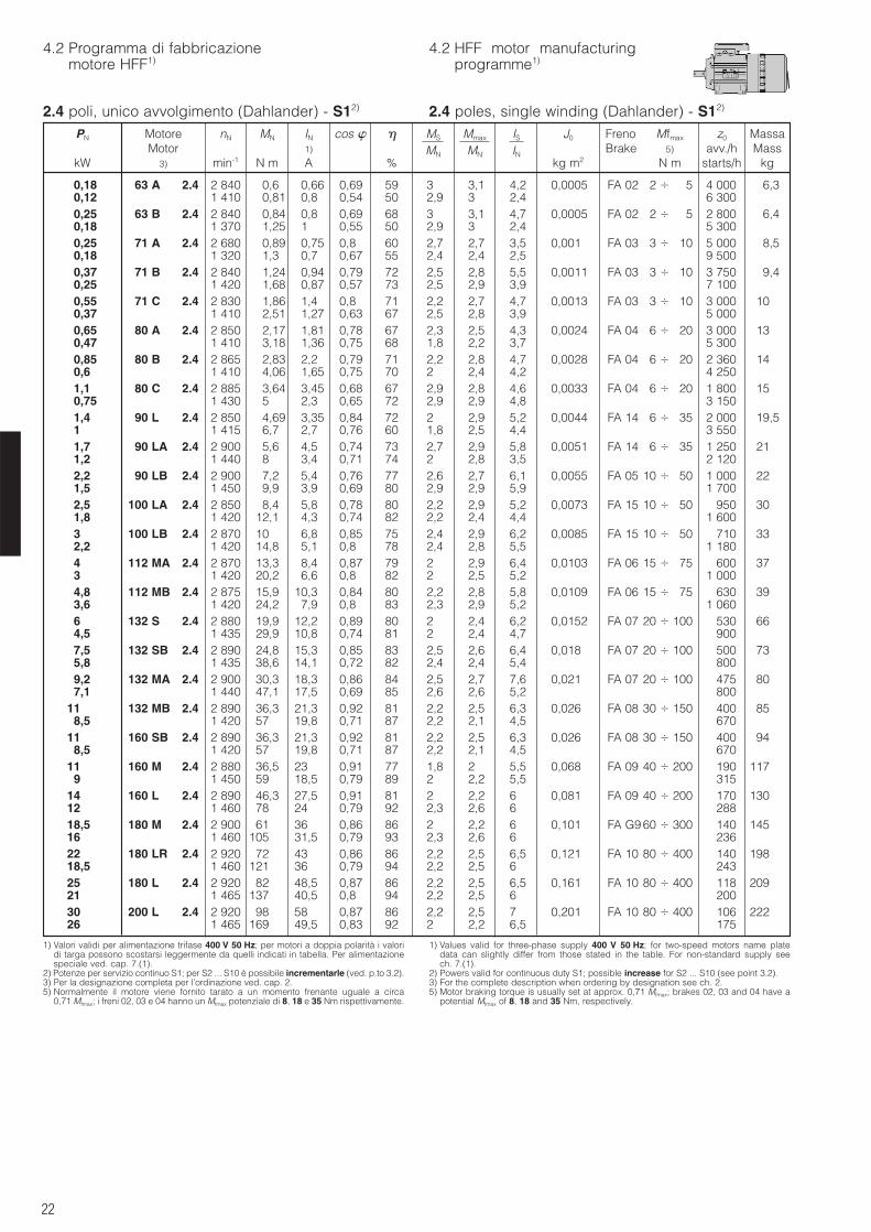
22
4.2 Programma di fabbricazionemotore HFF1)
1) Valori validi per alimentazione trifase 400 V 50 Hz; per motori a doppia polarità i valoridi targa possono scostarsi leggermente da quelli indicati in tabella. Per alimentazionespeciale ved. cap. 7.(1).
2) Potenze per servizio continuo S1; per S2 ... S10 è possibile incrementarle (ved. p.to 3.2).3) Per la designazione completa per l’ordinazione ved. cap. 2.5) Normalmente il motore viene fornito tarato a un momento frenante uguale a circa
0,71 Mfmax; i freni 02, 03 e 04 hanno un Mfmax potenziale di 8, 18 e 35 Nm rispettivamente.
1) Values valid for three-phase supply 400 V 50 Hz; for two-speed motors name platedata can slightly differ from those stated in the table. For non-standard supply seech. 7.(1).
2) Powers valid for continuous duty S1; possible increase for S2 ... S10 (see point 3.2).3) For the complete description when ordering by designation see ch. 2.5) Motor braking torque is usually set at approx. 0,71 Mfmax; brakes 02, 03 and 04 have a
potential Mfmax of 8, 18 and 35 Nm, respectively.
4.2 HFF motor manufacturingprogramme1)
PN Motore nN MN IN cos MS Mmax IS J0 Freno Mfmax z0 MassaMotor 1) MN MN IN Brake 5) avv./h Mass
kW 3) min-1 N m A % kg m2 N m starts/h kg
0,18 63 A 2.4 2 840 0,6 0,66 0,69 59 3 3,1 4,2 0,0005 FA 02 2 5 4 000 6,30,12 1 410 0,81 0,8 0,54 50 2,9 3 2,4 6 3000,25 63 B 2.4 2 840 0,84 0,8 0,69 68 3 3,1 4,7 0,0005 FA 02 2 5 2 800 6,40,18 1 370 1,25 1 0,55 50 2,9 3 2,4 5 3000,25 71 A 2.4 2 680 0,89 0,75 0,8 60 2,7 2,7 3,5 0,001 FA 03 3 10 5 000 8,50,18 1 320 1,3 0,7 0,67 55 2,4 2,4 2,5 9 5000,37 71 B 2.4 2 840 1,24 0,94 0,79 72 2,5 2,8 5,5 0,0011 FA 03 3 10 3 750 9,40,25 1 420 1,68 0,87 0,57 73 2,5 2,9 3,9 7 1000,55 71 C 2.4 2 830 1,86 1,4 0,8 71 2,2 2,7 4,7 0,0013 FA 03 3 10 3 000 100,37 1 410 2,51 1,27 0,63 67 2,5 2,8 3,9 5 0000,65 80 A 2.4 2 850 2,17 1,81 0,78 67 2,3 2,5 4,3 0,0024 FA 04 6 20 3 000 130,47 1 410 3,18 1,36 0,75 68 1,8 2,2 3,7 5 3000,85 80 B 2.4 2 865 2,83 2,2 0,79 71 2,2 2,8 4,7 0,0028 FA 04 6 20 2 360 140,6 1 410 4,06 1,65 0,75 70 2 2,4 4,2 4 2501,1 80 C 2.4 2 885 3,64 3,45 0,68 67 2,9 2,8 4,6 0,0033 FA 04 6 20 1 800 150,75 1 430 5 2,3 0,65 72 2,9 2,9 4,8 3 1501,4 90 L 2.4 2 850 4,69 3,35 0,84 72 2 2,9 5,2 0,0044 FA 14 6 35 2 000 19,51 1 415 6,7 2,7 0,76 60 1,8 2,5 4,4 3 5501,7 90 LA 2.4 2 900 5,6 4,5 0,74 73 2,7 2,9 5,8 0,0051 FA 14 6 35 1 250 211,2 1 440 8 3,4 0,71 74 2 2,8 3,5 2 1202,2 90 LB 2.4 2 900 7,2 5,4 0,76 77 2,6 2,7 6,1 0,0055 FA 05 10 50 1 000 221,5 1 450 9,9 3,9 0,69 80 2,9 2,9 5,9 1 7002,5 100 LA 2.4 2 850 8,4 5,8 0,78 80 2,2 2,9 5,2 0,0073 FA 15 10 50 950 301,8 1 420 12,1 4,3 0,74 82 2,2 2,4 4,4 1 6003 100 LB 2.4 2 870 10 6,8 0,85 75 2,4 2,9 6,2 0,0085 FA 15 10 50 710 332,2 1 420 14,8 5,1 0,8 78 2,4 2,8 5,5 1 1804 112 MA 2.4 2 870 13,3 8,4 0,87 79 2 2,9 6,4 0,0103 FA 06 15 75 600 373 1 420 20,2 6,6 0,8 82 2 2,5 5,2 1 0004,8 112 MB 2.4 2 875 15,9 10,3 0,84 80 2,2 2,8 5,8 0,0109 FA 06 15 75 630 393,6 1 420 24,2 7,9 0,8 83 2,3 2,9 5,2 1 0606 132 S 2.4 2 880 19,9 12,2 0,89 80 2 2,4 6,2 0,0152 FA 07 20 100 530 664,5 1 435 29,9 10,8 0,74 81 2 2,4 4,7 9007,5 132 SB 2.4 2 890 24,8 15,3 0,85 83 2,5 2,6 6,4 0,018 FA 07 20 100 500 735,8 1 435 38,6 14,1 0,72 82 2,4 2,4 5,4 8009,2 132 MA 2.4 2 900 30,3 18,3 0,86 84 2,5 2,7 7,6 0,021 FA 07 20 100 475 807,1 1 440 47,1 17,5 0,69 85 2,6 2,6 5,2 800
11 132 MB 2.4 2 890 36,3 21,3 0,92 81 2,2 2,5 6,3 0,026 FA 08 30 150 400 858,5 1 420 57 19,8 0,71 87 2,2 2,1 4,5 670
11 160 SB 2.4 2 890 36,3 21,3 0,92 81 2,2 2,5 6,3 0,026 FA 08 30 150 400 948,5 1 420 57 19,8 0,71 87 2,2 2,1 4,5 670
11 160 M 2.4 2 880 36,5 23 0,91 77 1,8 2 5,5 0,068 FA 09 40 200 190 1179 1 450 59 18,5 0,79 89 2 2,2 5,5 315
14 160 L 2.4 2 890 46,3 27,5 0,91 81 2 2,2 6 0,081 FA 09 40 200 170 13012 1 460 78 24 0,79 92 2,3 2,6 6 28818,5 180 M 2.4 2 900 61 36 0,86 86 2 2,2 6 0,101 FA G9 60 300 140 14516 1 460 105 31,5 0,79 93 2,3 2,6 6 23622 180 LR 2.4 2 920 72 43 0,86 86 2,2 2,5 6,5 0,121 FA 10 80 400 140 19818,5 1 460 121 36 0,79 94 2,2 2,5 6 24325 180 L 2.4 2 920 82 48,5 0,87 86 2,2 2,5 6,5 0,161 FA 10 80 400 118 20921 1 465 137 40,5 0,8 94 2,2 2,5 6 20030 200 L 2.4 2 920 98 58 0,87 86 2,2 2,5 7 0,201 FA 10 80 400 106 22226 1 465 169 49,5 0,83 92 2 2,2 6,5 175
2.4 poles, single winding (Dahlander) - S12)2.4 poli, unico avvolgimento (Dahlander) - S12)
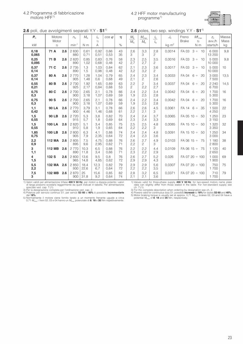
23
4.2 Programma di fabbricazionemotore HFF1)
4.2 HFF motor manufacturingprogramme1)
2.6 poli, due avvolgimenti separati Y.Y - S14)
1) Valori validi per alimentazione trifase 400 V 50 Hz; per motori a doppia polarità i valoridi targa possono scostarsi leggermente da quelli indicati in tabella. Per alimentazionespeciale ved. cap. 7.(1).
3) Per la designazione completa per l’ordinazione ved. cap. 2.4) Potenze per servizio continuo S1; per servizi S3 60 e 40% è possibile incrementarle
del 18%.5) Normalmente il motore viene fornito tarato a un momento frenante uguale a circa
0,71 Mfmax; i freni 02, 03 e 04 hanno un Mfmax potenziale di 8, 18 e 35 Nm rispettivamente.
1) Values valid for three-phase supply 400 V 50 Hz; for two-speed motors name platedata can slightly differ from those stated in the table. For non-standard supply seech. 7.(1).
3) For the complete description when ordering by designation see ch. 2.4) Powers valid for continuous duty S1; possible increase to 18% for duties S3 60 and 40%.5) Motor braking torque is usually set at approx. 0,71 Mfmax; brakes 02, 03 and 04 have a
potential Mfmax of 8, 18 and 35 Nm, respectively.
2.6 poles, two sep. windings Y.Y - S14)
PN Motore nN MN IN cos MS Mmax IS J0 Freno Mfmax z0 MassaMotor 1) MN MN IN Brake 5) avv./h Mass
kW 3) min-1 N m A % kg m2 N m starts/h kg
0,18 71 A 2.6 2 830 0,61 0,92 0,66 43 2,6 3,3 2,8 0,0014 FA 03 3 10 6 000 9,80,065 880 0,71 0,51 0,53 35 3 3 2 13 2000,25 71 B 2.6 2 820 0,85 0,83 0,76 58 2,3 2,5 3,5 0,0016 FA 03 3 10 5 000 9,80,095 890 1,02 0,68 0,48 42 2,7 2,7 2 10 0000,37 71 C 2.6 2 735 1,3 1,03 0,84 62 2,1 2,3 3,6 0,0017 FA 03 3 10 5 000 100,14 890 1,5 0,98 0,48 42 3,2 3,2 2 10 0000,37 80 A 2.6 2 770 1,28 1,04 0,79 65 2,4 2,3 3,4 0,0033 FA 04 6 20 3 000 13,50,14 905 1,48 0,6 0,68 49 2,1 2 2,6 7 5000,55 80 B 2.6 2 730 1,92 1,65 0,89 63 2,2 2 3,4 0,0037 FA 04 6 20 2 240 14,50,21 925 2,17 0,84 0,68 53 2 2,2 2,7 6 7000,75 80 C 2.6 2 700 2,65 2,1 0,78 66 2,4 2,2 3,4 0,0042 FA 04 6 20 1 700 160,3 900 3,18 1,07 0,69 59 1,9 2,5 2,8 5 3000,75 90 S 2.6 2 700 2,65 2,1 0,78 66 2,4 2,2 3,4 0,0042 FA 04 6 20 1 700 160,3 900 3,18 1,07 0,69 59 1,9 2,5 2,8 5 3001,1 90 LA 2.6 2 770 3,79 3,1 0,78 66 2,6 2,6 4,5 0,0061 FA 14 6 35 1 500 220,42 900 4,46 1,46 0,68 61 2,2 2,1 3 4 2501,5 90 LB 2.6 2 720 5,3 3,8 0,82 70 2,4 2,4 3,7 0,0065 FA 05 10 50 1 250 230,55 915 5,7 1,8 0,69 64 2,3 2,4 3,3 3 1501,5 100 LA 2.6 2 820 5,1 3,4 0,85 75 2,5 2,5 4,8 0,0085 FA 15 10 50 1 320 320,55 910 5,8 1,9 0,65 64 2,2 2,2 3 3 3501,85 100 LB 2.6 2 800 6,3 4,1 0,88 74 2,4 2,4 4,8 0,0091 FA 15 10 50 1 250 340,75 905 7,9 2,35 0,64 72 2,4 2,3 3,6 3 0002,2 112 MA 2.6 2 805 7,5 4,75 0,88 76 2,6 2,7 4,9 0,0103 FA 06 15 75 1 180 380,9 895 9,6 2,95 0,62 71 2,2 2 3 2 8003 112 MB 2.6 2 770 10,3 6,5 0,88 76 2,2 2,2 4,4 0,0109 FA 06 15 75 1 120 401,1 890 11,8 3,4 0,66 71 2,3 2,2 2,9 2 6504 132 S 2.6 2 800 13,6 9,5 0,8 76 2,6 2,7 5,2 0,026 FA 07 20 100 1 000 691,5 965 14,8 4,85 0,62 72 2,9 2,9 4,3 1 9005,5 132 MA 2.6 2 850 18,4 12,3 0,82 79 2,9 2,9 5,6 0,0307 FA 07 20 100 750 752,2 930 22,6 6,7 0,64 72 2,2 2,2 3,5 1 7007,5 132 MB 2.6 2 870 25 15,6 0,85 82 2,8 3,2 6,5 0,0371 FA 07 20 100 710 793 900 31,8 9,2 0,64 74 2,1 2,1 3,6 1 700
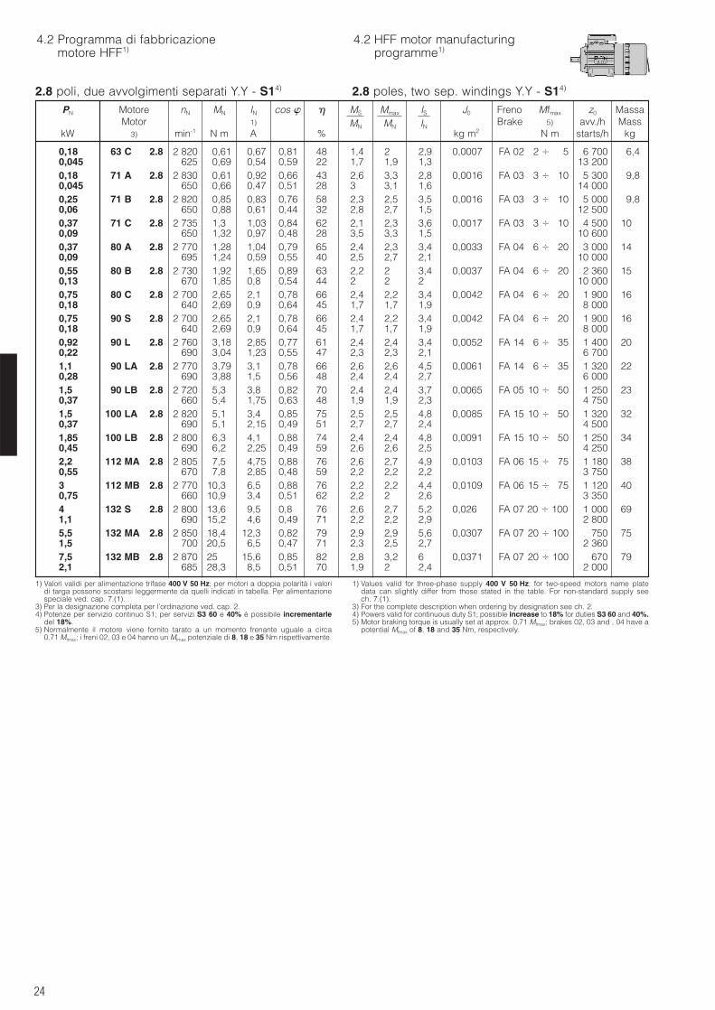
24
4.2 Programma di fabbricazionemotore HFF1)
4.2 HFF motor manufacturingprogramme1)
2.8 poli, due avvolgimenti separati Y.Y - S14)
1) Valori validi per alimentazione trifase 400 V 50 Hz; per motori a doppia polarità i valoridi targa possono scostarsi leggermente da quelli indicati in tabella. Per alimentazionespeciale ved. cap. 7.(1).
3) Per la designazione completa per l’ordinazione ved. cap. 2.4) Potenze per servizio continuo S1; per servizi S3 60 e 40% è possibile incrementarle
del 18%.5) Normalmente il motore viene fornito tarato a un momento frenante uguale a circa
0,71 Mfmax; i freni 02, 03 e 04 hanno un Mfmax potenziale di 8, 18 e 35 Nm rispettivamente.
1) Values valid for three-phase supply 400 V 50 Hz; for two-speed motors name platedata can slightly differ from those stated in the table. For non-standard supply seech. 7.(1).
3) For the complete description when ordering by designation see ch. 2.4) Powers valid for continuous duty S1; possible increase to 18% for duties S3 60 and 40%.5) Motor braking torque is usually set at approx. 0,71 Mfmax; brakes 02, 03 and , 04 have a
potential Mfmax of 8, 18 and 35 Nm, respectively.
2.8 poles, two sep. windings Y.Y - S14)
PN Motore nN MN IN cos MS Mmax IS J0 Freno Mfmax z0 MassaMotor 1) MN MN IN Brake 5) avv./h Mass
kW 3) min-1 N m A % kg m2 N m starts/h kg
0,18 63 C 2.8 2 820 0,61 0,67 0,81 48 1,4 2 2,9 0,0007 FA 02 2 5 6 700 6,40,045 625 0,69 0,54 0,59 22 1,7 1,9 1,3 13 2000,18 71 A 2.8 2 830 0,61 0,92 0,66 43 2,6 3,3 2,8 0,0016 FA 03 3 10 5 300 9,80,045 650 0,66 0,47 0,51 28 3 3,1 1,6 14 0000,25 71 B 2.8 2 820 0,85 0,83 0,76 58 2,3 2,5 3,5 0,0016 FA 03 3 10 5 000 9,80,06 650 0,88 0,61 0,44 32 2,8 2,7 1,5 12 5000,37 71 C 2.8 2 735 1,3 1,03 0,84 62 2,1 2,3 3,6 0,0017 FA 03 3 10 4 500 100,09 650 1,32 0,97 0,48 28 3,5 3,3 1,5 10 6000,37 80 A 2.8 2 770 1,28 1,04 0,79 65 2,4 2,3 3,4 0,0033 FA 04 6 20 3 000 140,09 695 1,24 0,59 0,55 40 2,5 2,7 2,1 10 0000,55 80 B 2.8 2 730 1,92 1,65 0,89 63 2,2 2 3,4 0,0037 FA 04 6 20 2 360 150,13 670 1,85 0,8 0,54 44 2 2 2 10 0000,75 80 C 2.8 2 700 2,65 2,1 0,78 66 2,4 2,2 3,4 0,0042 FA 04 6 20 1 900 160,18 640 2,69 0,9 0,64 45 1,7 1,7 1,9 8 0000,75 90 S 2.8 2 700 2,65 2,1 0,78 66 2,4 2,2 3,4 0,0042 FA 04 6 20 1 900 160,18 640 2,69 0,9 0,64 45 1,7 1,7 1,9 8 0000,92 90 L 2.8 2 760 3,18 2,85 0,77 61 2,4 2,4 3,4 0,0052 FA 14 6 35 1 400 200,22 690 3,04 1,23 0,55 47 2,3 2,3 2,1 6 7001,1 90 LA 2.8 2 770 3,79 3,1 0,78 66 2,6 2,6 4,5 0,0061 FA 14 6 35 1 320 220,28 690 3,88 1,5 0,56 48 2,4 2,4 2,7 6 0001,5 90 LB 2.8 2 720 5,3 3,8 0,82 70 2,4 2,4 3,7 0,0065 FA 05 10 50 1 250 230,37 660 5,4 1,75 0,63 48 1,9 1,9 2,3 4 7501,5 100 LA 2.8 2 820 5,1 3,4 0,85 75 2,5 2,5 4,8 0,0085 FA 15 10 50 1 320 320,37 690 5,1 2,15 0,49 51 2,7 2,7 2,4 4 5001,85 100 LB 2.8 2 800 6,3 4,1 0,88 74 2,4 2,4 4,8 0,0091 FA 15 10 50 1 250 340,45 690 6,2 2,25 0,49 59 2,6 2,6 2,5 4 2502,2 112 MA 2.8 2 805 7,5 4,75 0,88 76 2,6 2,7 4,9 0,0103 FA 06 15 75 1 180 380,55 670 7,8 2,85 0,48 59 2,2 2,2 2,2 3 7503 112 MB 2.8 2 770 10,3 6,5 0,88 76 2,2 2,2 4,4 0,0109 FA 06 15 75 1 120 400,75 660 10,9 3,4 0,51 62 2,2 2 2,6 3 3504 132 S 2.8 2 800 13,6 9,5 0,8 76 2,6 2,7 5,2 0,026 FA 07 20 100 1 000 691,1 690 15,2 4,6 0,49 71 2,2 2,2 2,9 2 8005,5 132 MA 2.8 2 850 18,4 12,3 0,82 79 2,9 2,9 5,6 0,0307 FA 07 20 100 750 751,5 700 20,5 6,5 0,47 71 2,3 2,5 2,7 2 3607,5 132 MB 2.8 2 870 25 15,6 0,85 82 2,8 3,2 6 0,0371 FA 07 20 100 670 792,1 685 28,3 8,5 0,51 70 1,9 2 2,4 2 000
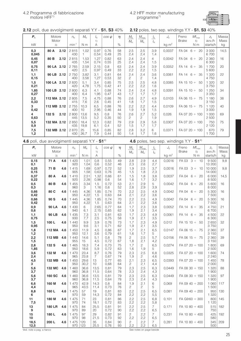
25
4.2 Programma di fabbricazionemotore HFF1)
4.2 HFF motor manufacturingprogramme1)
2.12 poli, due avvolgimenti separati Y.Y - S1. S3 40%
4.6 poli, due avvolgimenti separati Y.Y - S14) 4.6 poles, two sep. windings Y.Y - S14)
2.12 poles, two sep. windings Y.Y - S1. S3 40%
PN Motore nN MN IN cos MS Mmax IS J0 Freno Mfmax z0 MassaMotor 1) MN MN IN Brake 5) avv./h Mass
kW 3) min-1 N m A % kg m2 N m starts/h kg
0,15 71 A 4.6 1 420 1,01 0,8 0,55 49 2,8 2,9 4,4 0,0016 FA 03 3 10 9 500 9,80,1 920 1,04 0,6 0,52 46 2,3 2,6 2,7 13 2000,25 71 B 4.6 1 415 1,69 0,97 0,72 52 1,9 2,5 3,7 0,0016 FA 03 3 10 10 000 9,80,15 905 1,58 0,63 0,76 45 1,5 1,8 2,3 14 0000,37 80 A 4.6 1 410 2,51 1,32 0,66 61 1,5 1,8 3,8 0,0037 FA 04 6 20 6 000 14,50,22 920 2,28 0,98 0,6 54 1,6 1,7 3,2 8 5000,5 80 B 4.6 1 455 3,34 1,5 0,72 53 2,1 2,9 5 0,0042 FA 04 6 20 5 600 160,3 960 3 1,16 0,6 52 2,8 2,9 3,9 8 0000,66 80 C 4.6 1 445 4,36 1,85 0,74 70 2,2 2,5 4,9 0,0042 FA 04 6 20 5 300 160,42 950 4,22 1,5 0,63 64 2,1 2,2 3,6 7 5000,66 90 S 4.6 1 445 4,36 1,85 0,74 70 2,2 2,5 4,9 0,0042 FA 04 6 20 5 300 160,42 950 4,22 1,5 0,63 64 2,1 2,2 3,6 7 5000,9 90 LA 4.6 1 430 6 2,65 0,77 64 1,7 2,3 3,8 0,0052 FA 14 6 35 4 750 210,6 940 6,1 2,15 0,65 62 1,9 2,1 3,4 6 7001,1 90 LB 4.6 1 435 7,3 3,1 0,81 63 1,7 2,3 4,9 0,0061 FA 14 6 35 4 500 220,75 930 7,7 2,5 0,75 58 1,9 2,1 3,5 6 3001,5 100 L 4.6 1 440 9,9 3,9 0,76 73 1,7 2,3 4,9 0,012 FA 15 10 50 2 650 320,95 950 9,6 3,1 0,71 62 1,9 2,1 3,5 3 7501,8 112 MA 4.6 1 450 11,9 4,5 0,86 67 1,7 2,1 6,5 0,0147 FA 06 15 75 2 360 371,2 950 12,1 3,6 0,79 61 1,6 1,7 5 3 1502,2 112 MB 4.6 1 440 14,6 5,1 0,8 78 2 2,5 5,7 0,0156 FA 06 15 75 2 360 391,5 955 15 4,5 0,72 67 1,8 2,1 4,2 3 1502,8 132 S 4.6 1 465 18,3 7,4 0,73 75 1,7 2 6,5 0,0274 FA 07 20 100 1 800 691,85 950 18,6 5,9 0,72 63 1,6 1,9 5 2 5003,6 132 M 4.6 1 470 23,4 8,7 0,76 79 2,3 2,5 6,8 0,0325 FA 07 20 100 1 600 742,4 965 23,8 7 0,67 74 1,9 2 4,6 2 2404,5 132 MB 4.6 1 450 29,6 13 0,77 65 2,1 2,3 6,5 0,0393 FA 07 20 100 1 450 783 950 30,2 10 0,68 64 2 2,1 4,4 2 0005,6 132 MC 4.6 1 460 36,6 13,5 0,81 79 2,3 2,5 6,3 0,0449 FA 08 30 150 1 320 883,7 960 36,8 11,5 0,64 78 2,3 2,4 4,3 1 9005,6 160 SC 4.6 1 460 36,6 13,5 0,81 79 2,3 2,5 6,3 0,0449 FA 08 30 150 1 320 973,7 960 36,8 11,5 0,64 78 2,3 2,4 4,3 1 9006,6 160 M 4.6 1 470 42,9 14,3 0,8 84 1,9 2,1 6 0,069 FA 09 40 200 1 060 1174,4 965 43,5 11,4 0,73 76 2 2 5 1 5008,8 160 L 4.6 1 475 57 19 0,81 83 2,2 2,5 6,5 0,081 FA 09 40 200 950 1306 970 59 14,3 0,72 84 2,2 2,2 5,5 1 320
11 180 M 4.6 1 475 71 23 0,81 86 2,2 2,5 6,8 0,101 FA G9 60 300 800 1457,5 970 74 18,1 0,72 83 2,2 2,2 5,8 1 120
13 180 LR 4.6 1 475 84 25,5 0,81 91 2,2 2,5 7 0,171 FA 10 80 400 515 1829 970 89 20 0,72 90 2,2 2,2 6,5 750
15 180 L 4.6 1 475 97 29 0,82 91 2 2,2 7 0,231 FA 10 80 400 425 19210 970 98 21,5 0,73 92 2,2 2,2 6,5 58018,5 200 L 4.6 1 475 120 35 0,84 90 2 2,2 7 0,281 FA 10 80 400 345 20912,5 970 123 25,5 0,76 93 2,2 2,2 6,5 500
0,3 80 A 2.12 2 815 1,02 0,97 0,76 58 2,5 2,5 3,9 0,0037 FA 04 6 20 3 000 14,50,045 430 1 0,54 0,49 25 2,4 2,4 1,4 6 7000,45 80 B 2.12 2 815 1,53 1,27 0,82 63 2,4 2,4 4 0,0042 FA 04 6 20 2 360 160,07 435 1,54 0,74 0,55 25 2,4 2,4 1,5 6 3000,75 90 LA 2.12 2 765 2,59 2,15 0,8 63 2,4 2,4 3,9 0,0052 FA 14 6 35 1 700 200,11 420 2,5 0,97 0,49 33 2,2 2,2 1,5 5 6001,1 90 LB 2.12 2 750 3,82 3,1 0,81 64 2,4 2,4 3,6 0,0061 FA 14 6 35 1 320 220,15 400 3,58 1,27 0,53 32 2 2 1,4 4 7501,5 100 LA 2.12 2 820 5,1 3,4 0,85 75 2,5 2,5 4,8 0,0085 FA 15 10 50 1 320 320,21 420 4,78 1,75 0,42 41 2,2 2,2 1,6 3 7501,85 100 LB 2.12 2 800 6,3 4,1 0,88 74 2,4 2,4 4,8 0,0091 FA 15 10 50 1 250 340,27 400 6,4 1,95 0,47 43 1,7 1,7 1,7 3 3502,2 112 MA 2.12 2 805 7,5 4,75 0,88 76 2,6 2,7 4,9 0,0103 FA 06 15 75 1 180 380,33 415 7,6 2,6 0,45 41 1,8 1,7 1,5 3 1503 112 MB 2.12 2 755 10,3 6,5 0,88 76 2,2 2,2 4,4 0,0109 FA 06 15 75 1 120 400,42 400 10 2,95 0,46 44 1,9 1,9 1,5 3 0004 132 S 2.12 2 800 13,6 9,5 0,8 76 2,6 2,7 5,2 0,026 FA 07 20 100 1 000 690,63 445 13,5 5,2 0,35 50 2 2 1,9 2 5005,5 132 MA 2.12 2 850 18,4 12,3 0,82 79 2,9 2,9 5,6 0,0307 FA 07 20 100 750 750,9 435 19,8 6,1 0,4 52 1,5 1,7 1,7 2 1207,5 132 MB 2.12 2 870 25 15,6 0,85 82 2,8 3,2 6 0,0371 FA 07 20 100 670 791,2 430 26,7 7,9 0,44 50 1,4 1,7 1,6 1 700
PN Motore nN MN IN cos MS Mmax IS J0 Freno Mfmax z0 MassaMotor 1) MN MN IN Brake 5) avv./h Mass
kW 3) min-1 N m A % kg m2 N m starts/h kg
Ved. note a pag. a fianco See notes on page beside
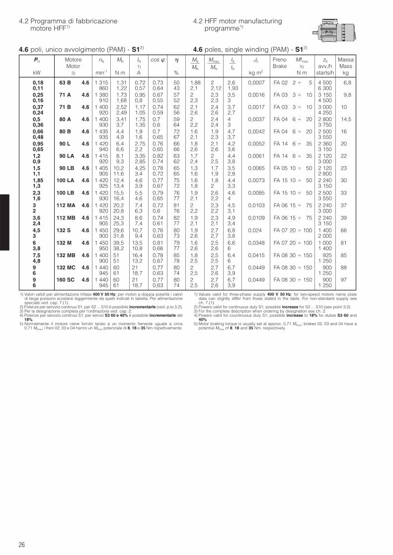
26
4.2 Programma di fabbricazionemotore HFF1)
4.2 HFF motor manufacturingprogramme1)
4.6 poli, unico avvolgimento (PAM) - S12) 4.6 poles, single winding (PAM) - S12)
0,18 63 B 4.6 1 315 1,31 0,72 0,73 50 1,88 2 2,6 0,0007 FA 02 2 5 4 500 6,80,11 860 1,22 0,57 0,64 43 2,1 2,12 1,93 6 3000,25 71 A 4.6 1 380 1,73 0,95 0,67 57 2 2,3 3,5 0,0016 FA 03 3 10 3 150 9,80,16 910 1,68 0,8 0,55 52 2,3 2,3 3 4 5000,37 71 B 4.6 1 400 2,52 1,17 0,74 62 2,1 2,4 3,7 0,0017 FA 03 3 10 3 000 100,24 920 2,49 1,05 0,59 56 2,6 2,6 2,7 4 2500,5 80 A 4.6 1 400 3,41 1,75 0,7 59 2 2,4 4 0,0037 FA 04 6 20 2 800 14,50,36 930 3,7 1,35 0,6 64 2,2 2,4 3 3 7500,66 80 B 4.6 1 435 4,4 1,9 0,7 72 1,6 1,9 4,7 0,0042 FA 04 6 20 2 500 160,48 935 4,9 1,6 0,65 67 2,1 2,3 3,7 3 5500,95 90 L 4.6 1 420 6,4 2,75 0,76 66 1,8 2,1 4,2 0,0052 FA 14 6 35 2 360 200,65 940 6,6 2,2 0,65 66 2,6 2,6 3,6 3 1501,2 90 LA 4.6 1 415 8,1 3,35 0,82 63 1,7 2 4,4 0,0061 FA 14 6 35 2 120 220,9 920 9,3 2,85 0,74 62 2,4 2,5 3,8 3 0001,5 90 LB 4.6 1 405 10,2 4,25 0,78 65 1,3 1,7 3,5 0,0065 FA 05 10 50 2 120 231,1 905 11,6 3,4 0,72 65 1,6 1,9 2,8 2 8001,85 100 LA 4.6 1 420 12,4 4,6 0,77 75 1,6 1,8 4,4 0,0073 FA 15 10 50 2 240 301,3 925 13,4 3,9 0,67 72 1,8 2 3,3 3 1502,3 100 LB 4.6 1 420 15,5 5,5 0,79 76 1,9 2,6 4,6 0,0085 FA 15 10 50 2 500 331,6 930 16,4 4,6 0,65 77 2,1 2,2 4 3 5503 112 MA 4.6 1 420 20,2 7,4 0,72 81 2 2,3 4,5 0,0103 FA 06 15 75 2 240 372 920 20,8 6,3 0,6 76 2,2 2,2 3,1 3 0003,6 112 MB 4.6 1 415 24,3 8,6 0,74 82 1,9 2,3 4,9 0,0109 FA 06 15 75 2 240 392,4 905 25,3 7,4 0,61 77 2,1 2,1 3,4 3 1504,5 132 S 4.6 1 450 29,6 10,7 0,76 80 1,9 2,7 6,8 0,024 FA 07 20 100 1 400 663 900 31,8 9,4 0,63 73 2,6 2,7 3,8 2 0006 132 M 4.6 1 450 39,5 13,5 0,81 79 1,6 2,5 6,6 0,0348 FA 07 20 100 1 000 813,8 950 38,2 10,8 0,66 77 2,6 2,6 6 1 4007,5 132 MB 4.6 1 400 51 16,4 0,78 85 1,8 2,5 6,4 0,0415 FA 08 30 150 925 854,8 900 51 13,2 0,67 78 2,5 2,5 6 1 2509 132 MC 4.6 1 440 60 21 0,77 80 2 2,7 6,7 0,0449 FA 08 30 150 900 886 945 61 18,7 0,63 74 2,5 2,6 3,9 1 2509 160 SC 4.6 1 440 60 21 0,77 80 2 2,7 6,7 0,0449 FA 08 30 150 900 976 945 61 18,7 0,63 74 2,5 2,6 3,9 1 250
PN Motore nN MN IN cos MS Mmax IS J0 Freno Mfmax z0 MassaMotor 1) MN MN IN Brake 5) avv./h Mass
kW 3) min-1 N m A % kg m2 N m starts/h kg
1) Valori validi per alimentazione trifase 400 V 50 Hz; per motori a doppia polarità i valoridi targa possono scostarsi leggermente da quelli indicati in tabella. Per alimentazionespeciale ved. cap. 7.(1).
2) Potenze per servizio continuo S1; per S2 ... S10 è possibile incrementarle (ved. p.to 3.2).3) Per la designazione completa per l’ordinazione ved. cap. 2.4) Potenze per servizio continuo S1; per servizi S3 60 e 40% è possibile incrementarle del
18%.5) Normalmente il motore viene fornito tarato a un momento frenante uguale a circa
0,71 Mfmax; i freni 02, 03 e 04 hanno un Mfmax potenziale di 8, 18 e 35 Nm rispettivamente.
1) Values valid for three-phase supply 400 V 50 Hz; for two-speed motors name platedata can slightly differ from those stated in the table. For non-standard supply seech. 7.(1).
2) Powers valid for continuous duty S1; possible increase for S2 ... S10 (see point 3.2).3) For the complete description when ordering by designation see ch. 2.4) Powers valid for countinuous duty S1; possible increase to 18% for duties S3 60 and
40%5) Motor braking torque is usually set at approx. 0,71 Mfmax; brakes 02, 03 and 04 have a
potential Mfmax of 8, 18 and 35 Nm, respectively.
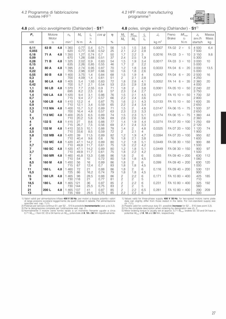
27
1) Valori validi per alimentazione trifase 400 V 50 Hz; per motori a doppia polarità i valoridi targa possono scostarsi leggermente da quelli indicati in tabella. Per alimentazionespeciale ved. cap. 7.(1).
2) Potenze per servizio continuo S1; per S2 ... S10 è possibile incrementarle (ved. p.to 3.2).3) Per la designazione completa per l’ordinazione ved. cap. 2.5) Normalmente il motore viene fornito tarato a un momento frenante uguale a circa
0,71 Mfmax; i freni 02, 03 e 04 hanno un Mfmax potenziale di 8, 18 e 35 Nm rispettivamente.
1) Values valid for three-phase supply 400 V 50 Hz; for two-speed motors name platedata can slightly differ from those stated in the table. For non-standard supply seech. 7.(1).
2) Powers valid for continuous duty S1; possible increase for S2 ... S10 (see point 3.2).3) For the complete description when ordering by designation see ch. 2.5) Motor braking torque is usually set at approx. 0,71 Mfmax; brakes 02, 03 and 04 have a
potential Mfmax of 8, 18 and 35 Nm, respectively.
4.8 poli, unico avvolgimento (Dahlander) - S12) 4.8 poles, single winding (Dahlander) - S12)
0,11 63 B 4.8 1 360 0,77 0,4 0,71 56 1,5 1,5 3,6 0,0007 FA 02 2 5 4 500 6,40,055 620 0,77 0,56 0,52 25 2,1 2,2 2,8 7 5000,18 71 A 4.8 1 350 1,27 0,74 0,7 50 1,7 2,2 3 0,0016 FA 03 3 10 3 150 9,80,09 670 1,28 0,68 0,51 37 2,4 2,5 1,9 5 3000,28 71 B 4.8 1 325 2,02 0,9 0,83 54 1,5 1,9 3,4 0,0017 FA 03 3 10 3 000 100,15 635 2,26 0,85 0,55 46 1,7 2 2,2 5 0000,4 80 A 4.8 1 395 2,74 0,95 0,87 70 1,2 1,8 3,8 0,0033 FA 04 6 20 3 000 13,50,22 705 2,98 0,97 0,66 50 1,6 1,8 2,6 5 0000,55 80 B 4.8 1 400 3,75 1,4 0,84 68 1,5 1,9 4 0,0042 FA 04 6 20 2 500 160,3 700 4,09 1,4 0,61 51 2 2,1 2,8 4 2500,8 90 LA 4.8 1 405 5,4 1,93 0,83 72 1,8 2,8 4,1 0,0052 FA 14 6 35 2 360 200,42 700 5,7 2,1 0,54 53 2,5 2,9 2,8 4 0001,1 90 LB 4.8 1 370 7,7 2,55 0,9 71 1,8 2 3,8 0,0061 FA 05 10 50 2 240 220,6 695 8,2 2,5 0,6 57 2,3 2,4 2,7 3 7501,4 100 LA 4.8 1 420 9,4 3,1 0,86 76 1,5 2,1 4,5 0,012 FA 15 10 50 1 700 320,7 715 9,4 2,7 0,57 66 2,2 2,4 3,6 2 8001,8 100 LB 4.8 1 410 12,2 4 0,87 75 1,6 2,1 4,3 0,0133 FA 15 10 50 1 600 350,9 710 12,1 3,4 0,59 65 2,2 2,4 3,4 2 6502,3 112 MA 4.8 1 400 15,7 5,2 0,89 71 1,5 2 4,8 0,0147 FA 06 15 75 1 500 371,2 700 16,4 4,8 0,57 63 2,3 2,3 3,3 2 6503 112 MC 4.8 1 400 20,5 6,5 0,89 74 1,5 2,3 5,1 0,0174 FA 06 15 75 1 360 441,5 710 20,2 5,6 0,56 69 2,6 2,6 3,6 2 3604 132 S 4.8 1 415 27 8,6 0,88 77 1,4 1,9 4,4 0,0274 FA 07 20 100 1 250 692 715 26,7 7,5 0,56 69 2,1 2,4 3,3 2 1204,8 132 M 4.8 1 410 32,5 10,1 0,88 78 1,4 2 4,8 0,0325 FA 07 20 100 1 120 742,5 710 33,6 8,5 0,59 72 2 2,1 4 1 9005,8 132 MB 4.8 1 420 39 11,5 0,89 82 1,2 1,9 4,7 0,0394 FA 07 20 100 950 823 710 40,4 9,6 0,6 76 1,8 2,1 3,8 1 6007 132 MC 4.8 1 420 47,1 14,2 0,89 80 1,2 1,8 5,1 0,0449 FA 08 30 150 900 883,7 710 49,8 11,7 0,61 75 1,8 2,2 4,2 1 5007 160 SC 4.8 1 420 47,1 14,2 0,89 80 1,2 1,8 5,1 0,0449 FA 08 30 150 900 973,7 710 49,8 11,7 0,61 75 1,8 2,2 4,2 1 5007 160 MR 4.8 1 460 45,8 13,3 0,88 86 1,8 2 6 0,093 FA 09 40 200 630 1124 710 54 10 0,72 80 1,8 1,8 4,5 1 0608,5 160 M 4.8 1 450 56 16 0,89 86 1,8 2 6 0,099 FA 09 40 200 630 1205 715 67 12,4 0,7 83 1,8 1,8 4,5 1 000
11 160 L 4.8 1 460 72 21 0,88 86 1,8 2 6 0,116 FA 09 40 200 530 1316,5 725 86 16,2 0,74 79 1,8 1,8 4,5 900
15 180 LR 4.8 1 465 98 28,5 0,88 86 2 2,2 6 0,171 FA 10 80 400 425 1859 730 118 21 0,77 81 2 2 5 710
18,5 180 L 4.8 1 465 121 36 0,87 85 2 2,2 6 0,231 FA 10 80 400 325 19211 730 144 25,5 0,75 83 2 2 5 56021 200 L 4.8 1 465 137 41 0,87 85 2 2,2 6,5 0,281 FA 10 80 400 290 20913 735 169 29,5 0,75 85 2,2 2,2 6 500
PN Motore nN MN IN cos MS Mmax IS J0 Freno Mfmax z0 MassaMotor 1) MN MN IN Brake 5) avv./h Mass
kW 3) min-1 N m A % kg m2 N m starts/h kg
4.2 Programma di fabbricazionemotore HFF1)
4.2 HFF motor manufacturingprogramme1)
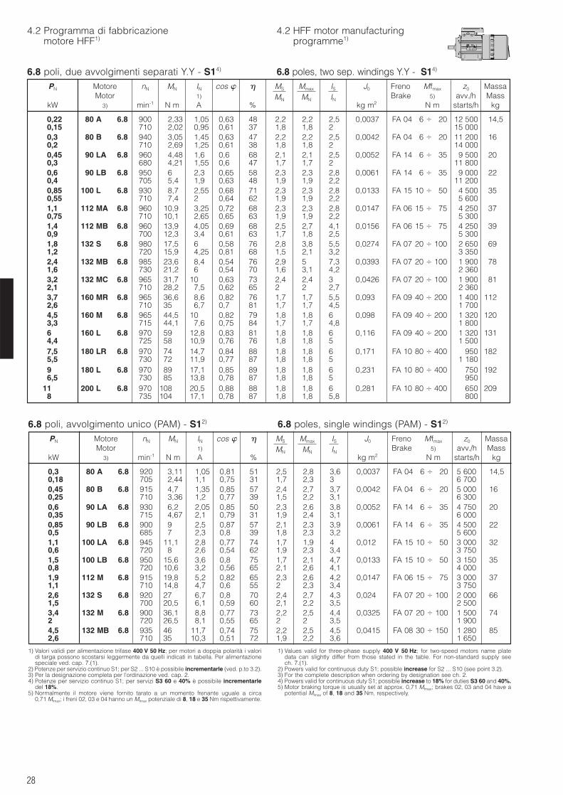
28
6.8 poli, avvolgimento unico (PAM) - S12) 6.8 poles, single windings (PAM) - S12)
1) Valori validi per alimentazione trifase 400 V 50 Hz; per motori a doppia polarità i valoridi targa possono scostarsi leggermente da quelli indicati in tabella. Per alimentazionespeciale ved. cap. 7.(1).
2) Potenze per servizio continuo S1; per S2 ... S10 è possibile incrementarle (ved. p.to 3.2).3) Per la designazione completa per l’ordinazione ved. cap. 2.4) Potenze per servizio continuo S1; per servizi S3 60 e 40% è possibile incrementarle
del 18%.5) Normalmente il motore viene fornito tarato a un momento frenante uguale a circa
0,71 Mfmax; i freni 02, 03 e 04 hanno un Mfmax potenziale di 8, 18 e 35 Nm rispettivamente.
1) Values valid for three-phase supply 400 V 50 Hz; for two-speed motors name platedata can slightly differ from those stated in the table. For non-standard supply seech. 7.(1).
2) Powers valid for continuous duty S1; possible increase for S2 ... S10 (see point 3.2).3) For the complete description when ordering by designation see ch. 2.4) Powers valid for continuous duty S1; possible increase to 18% for duties S3 60 and 40%.5) Motor braking torque is usually set at approx. 0,71 Mfmax; brakes 02, 03 and 04 have a
potential Mfmax of 8, 18 and 35 Nm, respectively.
0,3 80 A 6.8 920 3,11 1,05 0,81 51 2,5 2,8 3,6 0,0037 FA 04 6 20 5 600 14,50,18 705 2,44 1,1 0,75 31 1,7 2,3 3 6 7000,45 80 B 6.8 915 4,7 1,35 0,85 57 2,4 2,7 3,7 0,0042 FA 04 6 20 5 000 160,25 710 3,36 1,2 0,77 39 1,5 2,2 3,1 6 3000,6 90 LA 6.8 930 6,2 2,05 0,85 50 2,3 2,6 3,8 0,0052 FA 14 6 35 4 750 200,35 715 4,67 2,1 0,79 31 1,9 2,4 3,1 6 0000,85 90 LB 6.8 900 9 2,5 0,87 57 2,1 2,3 3,9 0,0061 FA 14 6 35 4 500 220,5 685 7 2,3 0,8 39 1,8 2,3 3,2 5 6001,1 100 LA 6.8 945 11,1 2,8 0,77 74 1,7 1,9 4 0,012 FA 15 10 50 3 000 320,6 720 8 2,6 0,54 62 1,9 2,3 3,4 3 7501,5 100 LB 6.8 950 15,6 3,6 0,8 75 1,7 2,1 4,7 0,0133 FA 15 10 50 3 150 350,8 720 10,6 3,2 0,56 65 2,1 2,6 4,1 4 0001,9 112 M 6.8 915 19,8 5,2 0,82 65 2,3 2,6 4,2 0,0147 FA 06 15 75 3 000 371,1 710 14,8 4,7 0,6 55 2 2,3 3,4 3 7502,6 132 S 6.8 920 27 6,7 0,8 70 2,4 2,7 4,3 0,024 FA 07 20 100 2 000 661,5 700 20,5 6,1 0,59 60 2,1 2,2 3,5 2 5003,4 132 M 6.8 900 36,1 8,8 0,77 73 2,2 2,5 4,4 0,0325 FA 07 20 100 1 500 742 720 26,5 8,1 0,55 65 2 2 3,5 1 9004,5 132 MB 6.8 935 46 11,7 0,74 75 2,2 2,5 4,5 0,0415 FA 08 30 150 1 280 852,6 710 35 10,3 0,51 72 1,9 2,2 3,6 1 650
PN Motore nN MN IN cos MS Mmax IS J0 Freno Mfmax z0 MassaMotor 1) MN MN IN Brake 5) avv./h Mass
kW 3) min-1 N m A % kg m2 N m starts/h kg
6.8 poli, due avvolgimenti separati Y.Y - S14) 6.8 poles, two sep. windings Y.Y - S14)
0,22 80 A 6.8 900 2,33 1,05 0,63 48 2,2 2,2 2,5 0,0037 FA 04 6 20 12 500 14,50,15 710 2,02 0,95 0,61 37 1,8 1,8 2 15 0000,3 80 B 6.8 940 3,05 1,45 0,63 47 2,2 2,2 2,5 0,0042 FA 04 6 20 11 200 160,2 710 2,69 1,25 0,61 38 1,8 1,8 2 14 0000,45 90 LA 6.8 960 4,48 1,6 0,6 68 2,1 2,1 2,5 0,0052 FA 14 6 35 9 500 200,3 680 4,21 1,55 0,6 47 1,7 1,7 2 11 8000,6 90 LB 6.8 950 6 2,3 0,65 58 2,3 2,3 2,8 0,0061 FA 14 6 35 9 000 220,4 705 5,4 1,9 0,63 48 1,9 1,9 2,2 11 2000,85 100 L 6.8 930 8,7 2,55 0,68 71 2,3 2,3 2,8 0,0133 FA 15 10 50 4 500 350,55 710 7,4 2 0,64 62 1,9 1,9 2,2 5 6001,1 112 MA 6.8 960 10,9 3,25 0,72 68 2,3 2,3 2,8 0,0147 FA 06 15 75 4 250 370,75 710 10,1 2,65 0,65 63 1,9 1,9 2,2 5 3001,4 112 MB 6.8 960 13,9 4,05 0,69 68 2,5 2,7 4,1 0,0156 FA 06 15 75 4 250 390,9 700 12,3 3,4 0,61 63 1,7 1,8 2,5 5 3001,8 132 S 6.8 980 17,5 6 0,58 76 2,8 3,8 5,5 0,0274 FA 07 20 100 2 650 691,2 720 15,9 4,25 0,81 68 1,5 2,1 3,2 3 3502,4 132 MB 6.8 985 23,6 8,4 0,54 76 2,9 5 7,3 0,0393 FA 07 20 100 1 900 781,6 730 21,2 6 0,54 70 1,6 3,1 4,2 2 3603,2 132 MC 6.8 965 31,7 10 0,63 73 2,4 2,4 3 0,0426 FA 07 20 100 1 900 812,1 710 28,2 7,5 0,62 65 2 2 2,7 2 3603,7 160 MR 6.8 965 36,6 8,6 0,82 76 1,7 1,7 5,5 0,093 FA 09 40 200 1 400 1122,6 710 35 6,7 0,7 81 1,7 1,7 4,5 1 7004,5 160 M 6.8 965 44,5 10 0,82 79 1,8 1,8 6 0,098 FA 09 40 200 1 320 1203,3 715 44,1 7,6 0,75 84 1,7 1,7 4,8 1 8006 160 L 6.8 970 59 12,8 0,83 81 1,8 1,8 6 0,116 FA 09 40 200 1 320 1314,4 725 58 10,9 0,76 76 1,8 1,8 5 1 5007,5 180 LR 6.8 970 74 14,7 0,84 88 1,8 1,8 6 0,171 FA 10 80 400 950 1825,5 730 72 11,9 0,77 87 1,8 1,8 5 1 1809 180 L 6.8 970 89 17,1 0,85 89 1,8 1,8 6 0,231 FA 10 80 400 750 1926,5 730 85 13,8 0,78 87 1,8 1,8 5 950
11 200 L 6.8 970 108 20,5 0,88 88 1,8 1,8 6 0,281 FA 10 80 400 650 2098 735 104 17,1 0,78 87 1,8 1,8 5,8 800
PN Motore nN MN IN cos MS Mmax IS J0 Freno Mfmax z0 MassaMotor 1) MN MN IN Brake 5) avv./h Mass
kW 3) min-1 N m A % kg m2 N m starts/h kg
4.2 Programma di fabbricazionemotore HFF1)
4.2 HFF motor manufacturingprogramme1)

29
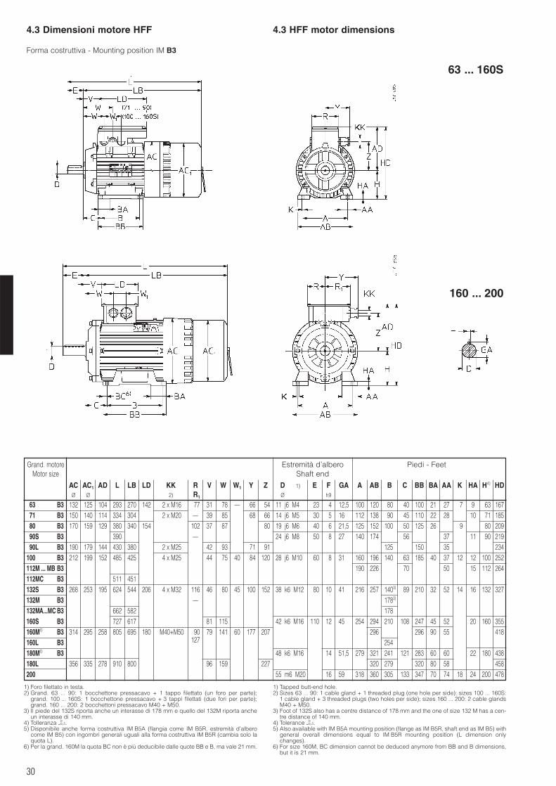
30
4.3 Dimensioni motore HFF 4.3 HFF motor dimensions
1) Foro filettato in testa.2) Grand. 63 ... 90: 1 bocchettone pressacavo + 1 tappo filettato (un foro per parte);
grand. 100 ... 160S: 1 bocchettone pressacavo + 3 tappi filettati (due fori per parte);grand. 160 ... 200: 2 bocchettoni pressacavo M40 + M50.
3) Il piede del 132S riporta anche un interasse di 178 mm e quello del 132M riporta ancheun interasse di 140 mm.
4) Tolleranza -oo,5.
5) Disponibile anche forma costruttiva IM B5A (flangia come IM B5R, estremità d’alberocome IM B5) con ingombri generali uguali alla forma costruttiva IM B5R (cambia solo laquota L).
6) Per la grand. 160M la quota BC non è più deducibile dalle quote BB e B, ma vale 21 mm.
1) Tapped butt-end hole.2) Sizes 63 ... 90: 1 cable gland + 1 threaded plug (one hole per side); sizes 100 ... 160S:
1 cable gland + 3 threaded plugs (two holes per side); sizes 160 ... 200: 2 cable glandsM40 + M50.
3) Foot of 132S also has a centre distance of 178 mm and the one of size 132 M has a cen-tre distance of 140 mm.
4) Tolerance -oo,5.
5) Also available with IM B5A mounting position (flange as IM B5R, shaft end as IM B5) withgeneral overall dimensions equal to IM B5R mounting position (L dimension onlychanges).
6) For size 160M, BC dimension cannot be deduced anymore from BB and B dimensions,but it is 21 mm.
Forma costruttiva - Mounting position IM B3
Grand. motore Estremità d’albero Piedi - FeetMotor size Shaft end
AC AC1 AD L LB LD KK R V W W1 Y Z D 1) E F GA A AB B C BB BA AA K HA H4) HDØ Ø 2) R1 Ø 1) h9
63 B3 132 125 104 293 270 142 2 x M16 77 31 78 – 66 54 11 j6 M4 23 4 12,5 100 120 80 40 100 21 27 7 9 63 16771 B3 150 140 114 334 304 2 x M20 – 39 85 68 66 14 j6 M5 30 5 16 112 138 90 45 110 22 28 10 71 18580 B3 170 159 129 380 340 154 102 37 87 80 19 j6 M6 40 6 21,5 125 152 100 50 125 26 9 80 20990S B3 390 – 24 j6 M8 50 8 27 140 174 56 37 11 90 21990L B3 190 179 144 430 380 2 x M25 42 93 71 91 125 150 35 234
100 B3 212 199 152 485 425 4 x M25 44 75 40 84 120 28 j6 M10 60 8 31 160 196 140 63 185 40 37 12 12 100 252112M ... MB B3 190 226 70 50 15 112 264112MC B3 511 451132S B3 268 253 195 624 544 206 4 x M32 116 46 80 45 100 152 38 k6 M12 80 10 41 216 257 1403) 89 210 32 52 14 16 132 327132M B3 – 1783)
132MA...MC B3 662 582 178160S B3 727 617 81 115 42 k6 M16 110 12 45 254 294 210 108 247 45 52 20 160 355160M6) B3 314 295 258 805 695 180 M40+M50 90 79 141 60 177 207 296 296 90 55 418160L B3 127 254180M6) B3 48 k6 M16 14 51,5 279 321 241 121 283 60 60 22 180 438180L 356 335 278 910 800 96 159 227 320 279 320 80 58 458200 55 m6 M20 16 59 318 360 305 133 347 70 74 18 24 200 478
160 ... 200
63 ... 160S
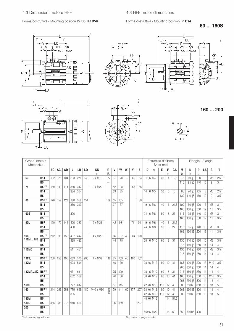
31
4.3 Dimensioni motore HFF 4.3 HFF motor dimensions
Forma costruttiva - Mounting position IM B5, IM B5R Forma costruttiva - Mounting position IM B14
Ved. note a pag. a fianco. See notes on page beside.
63 ... 160S
Grand. motoreMotor size
AC AC1 AD L LB LD KK R V W W1 Y Z D 1) E F GA M N P LA S T2) R1 Ø 1) h9 Ø Ø Ø Ø
Estremità d’alberoShaft end
Flangia - Flange
63 B14 132 125 104 293 270 142 2 x M16 77 31 78 – 66 54 11 j6 M4 23 4 12,5 75 60 j6 90 8 M5 2,5B5 – 115 95 j6 140 10 9 3
71 B5R5) 150 140 114 340 317 2 x M20 52 98 68 66B14 334 304 39 85 14 j6 M5 30 5 16 85 70 j6 105 8 M6 2,5B5 130 110 j6 160 10 9 3,5
80 B5R5) 170 159 129 388 358 154 102 55 105 80B14 380 340 – 37 87 19 j6 M6 40 6 21,5 100 80 j6 120 8 M6 3B5 165 130 j6 200 12 11 3,5
90S B14 390 24 j6 M8 50 8 27 115 95 j6 140 10 M8 3B5 165 130 j6 200 12 11 3,5
90L B5R 190 179 144 420 380 2 x M25 42 93 71 91 19 j6 M6 40 6 21,5B14 430 24 j6 M8 50 8 27 115 95 j6 140 10 M8 3B5 165 130 j6 200 12 11 3,5
100, B5R5) 212 199 152 497 447 4 x M25 66 97 40 84 120112M ... MB B14 485 425 44 75 28 j6 M10 60 8 31 130 110 j6 160 10 M8 3,5
B5 215 180 j6 250 14 14 4112MC B14 511 451 130 110 j6 160 10 M8 3,5
B5 215 180 j6 250 14 14 4132S, B5R5) 268 253 195 633 573 206 4 x M32 116 75 109 45 100 152132M B14 624 544 – 46 80 38 k6 M12 80 10 41 165 130 j6 200 13 M10 3,5
B5 265 230 j6 300 14 14 4132MA...MC B5R5) 671 611 75 109 28 j6 M10 60 8 31 215 180 j6 250 14 14 4
B14 662 582 46 80 38 k6 M12 80 10 41 165 130 j6 200 13 M10 3,5B5 265 230 j6 300 14 14 4
160S B5 727 617 81 115 42 k6 M16 110 12 45 300 250 h6 350 15 18 5160 B5R5) 314 295 258 775 695 180 M40 + M50 90 79 141 60 177 207 38 k6 M12 80 10 41 265 230 j6 300 14 14 4
B5 805 127 42 k6 M16 110 12 45 300 250 h6 350 15 18 5180M B5 48 k6 M16 14 51,5180L B5R5) 356 335 278 910 800 96 159 227200 B5R5)
B55) 55m6 M20 16 59 350 300 h6 400
160 ... 200
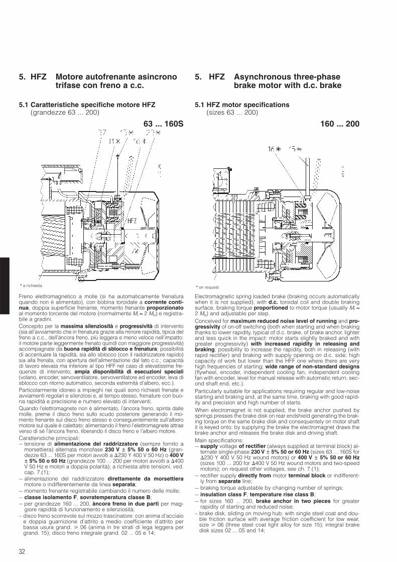
32
5. HFZ Motore autofrenante asincronotrifase con freno a c.c.
5. HFZ Asynchronous three-phasebrake motor with d.c. brake
5.1 Caratteristiche specifiche motore HFZ(grandezze 63 ... 200)
5.1 HFZ motor specifications(sizes 63 ... 200)
* a richiesta * on request
Freno elettromagnetico a molle (si ha automaticamente frenaturaquando non è alimentato), con bobina toroidale a corrente conti-nua, doppia superficie frenante, momento frenante proporzionatoal momento torcente del motore (normalmente Mf ≈ 2 MN) e registra-bile a gradini.Concepito per la massima silenziosità e progressività di intervento(sia all’avviamento che in frenatura grazie alla minore rapidità, tipica delfreno a c.c., dell’àncora freno, più leggera e meno veloce nell’impatto:il motore parte leggermente frenato quindi con maggiore progressività)accompagnate da buona rapidità di sblocco e frenatura; possibilitàdi accentuare la rapidità, sia allo sblocco (con il raddrizzatore rapido)sia alla frenata, con apertura dell’alimentazione dal lato c.c.; capacitàdi lavoro elevata ma inferiore al tipo HFF nel caso di elevatissime fre-quenze di intervento; ampia disponibilità di esecuzioni speciali(volano, encoder, servoventilatore, servoventilatore ed encoder, leva disblocco con ritorno automatico, seconda estremità d’albero, ecc.).Particolarmente idoneo a impieghi nei quali sono richiesti frenate eavviamenti regolari e silenziosi e, al tempo stesso, frenature con buo-na rapidità e precisione e numero elevato di interventi.Quando l’elettromagnete non è alimentato, l’àncora freno, spinta dallemolle, preme il disco freno sullo scudo posteriore generando il mo-mento frenante sul disco freno stesso e conseguentemente sull’alberomotore sul quale è calettato; alimentando il freno l’elettromagnete attraeverso di sé l’àncora freno, liberando il disco freno e l’albero motore.Caratteristiche principali:– tensione di alimentazione del raddrizzatore (sempre fornito a
morsettiera) alternata monofase 230 V ± 5% 50 o 60 Hz (gran-dezze 63 ... 160S per motori avvolti a 230 Y 400 V 50 Hz) o 400 V± 5% 50 o 60 Hz (grandezze 100 ... 200 per motori avvolti a 400V 50 Hz e motori a doppia polarità); a richiesta altre tensioni, ved.cap. 7.(1);
– alimentazione del raddrizzatore direttamente da morsettieramotore o indifferentemente da linea separata;
– momento frenante registrabile cambiando il numero delle molle;– classe isolamento F, sovratemperatura classe B;– per grandezze 160 ... 200, àncora freno in due parti per mag-
giore rapidità di funzionamento e silenziosità;– disco freno scorrevole sul mozzo trascinatore: con anima d’acciaio
e doppia guarnizione d’attrito a medio coefficiente d’attrito perbassa usura grand. 06 (anima in tre strati di lega leggera pergrand. 15); disco freno integrale grand. 02 ... 05 e 14;
Electromagnetic spring loaded brake (braking occurs automaticallywhen it is not supplied), with d.c. toroidal coil and double brakingsurface, braking torque proportioned to motor torque (usually Mf ≈2 MN) and adjustable per step.Conceived for maximum reduced noise level of running and pro-gressivity of on-off switching (both when starting and when brakingthanks to lower rapidity, typical of d.c. brake, of brake anchor, lighterand less quick in the impact: motor starts slightly braked and withgreater progressivity) with increased rapidity in releasing andbraking; possibility to increase the rapidity, both in releasing (withrapid rectifier) and braking with supply opening on d.c. side; highcapacity of work but lower than the HFF one where there are veryhigh frequencies of starting; wide range of non-standard designs(flywheel, encoder, independent cooling fan, independent coolingfan with encoder, level for manual release with automatic return, sec-ond shaft end, etc.).Particularly suitable for applications requiring regular and low-noisestarting and braking and, at the same time, braking with good rapid-ity and precision and high number of starts.When electromagnet is not supplied, the brake anchor pushed bysprings presses the brake disk on rear endshield generating the brak-ing torque on the same brake disk and consequentely on motor shaftit is keyed onto; by supplying the brake the electromagnet draws thebrake anchor and releases the brake disk and driving shaft.Main specifications:– supply voltage of rectifier (always supplied at terminal block) al-
ternate single-phase 230 V ± 5% 50 or 60 Hz (sizes 63 ... 160S for230 Y 400 V 50 Hz wound motors) or 400 V ± 5% 50 or 60 Hz(sizes 100 ... 200 for 400 V 50 Hz wound motors and two-speedmotors); on request other voltages, see ch. 7.(1);
– rectifier supply directly from motor terminal block or indifferent-ly from separate line;
– braking torque adjustable by changing number of springs;– insulation class F, temperature rise class B;– for sizes 160 ... 200, brake anchor in two pieces for greater
rapidity of starting and reduced noise;– brake disk, sliding on moving hub: with single steel coat and dou-
ble friction surface with average friction coefficient for low wear,size 06 (three steel coat light alloy for size 15); integral brakedisk sizes 02 ... 05 and 14;
63 ... 160S 160 ... 200
33
5.1 Caratteristiche specifiche motore HFZ(grandezze 63 ... 200)
5.1 HFZ motor specifications(sizes 63 ... 200)
– a richiesta: leva di sblocco manuale con ritorno automatico easta della leva asportabile; posizione leva di sblocco corrispon-dente alla scatola morsettiera come negli schemi al p.to 5.3; arichiesta, altre posizioni possibili; interpellarci;
– predisposizione per rotazione manuale per mezzo di chiavemaschio esagonale diritta (chiave 5 per grandezze 63 e 71, 6 per80 e 90, 8 per 100 e 112, 10 per 132 ... 160S, 12 per 160 ... 200)che si impegna sull’albero motore lato opposto comando (esclu-se le esecuzioni speciali «Servoventilatore assiale» e «Servoven-tilatore assiale ed encoder» cap. 7.((17), (18));
– guaina antipolvere ed antiacqua e V-ring (a richiesta per gran-dezze 63 ... 160S), sia per impedire l’entrata di inquinamento dal-l’esterno verso il freno sia per evitare che la polvere di usura dellaguarnizione di attrito venga dispersa nell’ambiente;
– protezione: IP 54 (IP 55, IP 56 e IP 65 a richiesta) per grandez-ze 63 ... 160S; IP 55 di serie per grandezze superiori; scatolamorsettiera IP 55;
– per altre caratteristiche funzionali ved. tabella seguente.Per caratteristiche generali motore ved. cap. 3.Per esecuzioni speciali ved. cap. 7.Il motore è sempre equipaggiato con raddrizzatore a elevata affi-dabilità fissato a scatola morsettiera e provvisto di adeguati morset-ti di collegamento (2 per alimentazione raddrizzatore diretta da mor-settiera motore oppure separata; 2 per contatto esterno di frenaturarapida, 3 ausiliari per servoventilatore o sonde termiche eventuali).Il raddrizzatore a diodi RN1 a semplice semionda (tensione uscitac.c. ≈ 0,45 tensione di alimentazione c.a., corrente massima conti-nuativa 1A) può essere inserito-disinserito sia lato c.a. (per la mas-sima silenziosità di funzionamento), sia lato c.a. e c.c. (per una mag-gior rapidità di frenatura), in quanto provvisto di varistori per laprotezione dei diodi, dell’elettromagnete e del contatto di aperturalato c.c. (schemi di collegamento al cap. 8).Per diminuire il tempo di sblocco è disponibile a richiesta ilraddrizzatore «rapido» RR110) per grandezze freno 02 ... 05 (fornitodi serie per grandezze 06 ... 09), ved. cap. 7.(27); protezioni e col-legamento equivalenti a RN1. Il raddrizzatore a diodi RR1 a sempli-ce semionda (tensione uscita c.c. ≈ 0,45 tensione di alimentazionec.a., corrente massima 2A all’inserzione, 1A continuativa) funziona adoppia semionda per i 600 (circa) ms iniziali fornendo alla bobinadel freno una tensione doppia; questo consente di ottenere unosblocco del freno molto più rapido.A richiesta sono disponibili raddrizzatori RN1X o RR1X per un ritar-do di frenatura «t2» ridotto con alimentazione diretta da morsettiera(ved. cap. 7.(38) e p.to 8.6).Tabella delle principali caratteristiche funzionali frenoI valori effettivi possono discostarsi leggermente in funzione dellatemperatura e della umidità ambiente, della temperatura del freno edello stato di usura delle guarnizioni di attrito.
– on request: lever for manual release with automatic return andremovable lever rod; position of release lever corresponding toterminal box as in the schemes at point 5.3; on request, other pos-sible positions; consult us;
– pre-arranged for manual rotation by straight setscrew (wrench 5for sizes 63 and 71, 6 for 80 and 90, 8 for 100 and 112, 10 for 132... 160S, 12 for 160 ... 200) that can be fitted on non-drive endmotor shaft (excluded non-standard designs «Axial independentcooling fan» and «Axial independent cooling fan and encoder»ch. 7.((17), (18));
– water-proof and dust-proof gaiter and V-ring (on request forsizes 63 ... 160S) both to prevent polluting infiltrations from sur-roundings towards brake, and to avoid that wear dust of frictionsurface will be dispersed in the surroundings;
– protection: IP 54 (IP 55, IP 56 and IP 65 on request) for sizes 63 ... 160S; IP 55 as standard for greater sizes; terminal box IP 55;
– for other functional specifications see following table.For main specifications of motor see ch. 3.For non-standard designs see ch. 7.Motor is always equipped with a high reliable rectifier fixed onterminal box providing adequate connecting terminal (2 for rectifiersupply directly from motor terminal block or separate; 2 for externalcontact of rapid braking, 3 auxiliary for independent cooling fan orthermal probes, if any).Simple half-wave diodes rectifier RN1 (output d.c. voltage ≈ 0,45 a.c.supply voltage, maximum continuative current 1A) can be connect-ed-disconnected both from a.c. side (for maximum reduced noiselevel of running) and from a.c. and d.c. side (for a quicker braking)because it is provided with varistors to protect diodes, electro-magnet and opening contact of d.c. side (wiring schemes at ch. 8).To decrease release time it is available a «rapid» rectifier RR110) onrequest for brake sizes 02 ... 05 (standard for sizes 06 ... 09), see ch.7.(27); protections and connection equivalent to RN1. Simplehalfwave diodes rectifier RR1 (output d.c. voltage ≈ 0,45 a.c. supplyvoltage, maximum current in connecting 2A, 1A continuative) runswith double half-wave for approx. initial 600 ms supplying to brake coila double voltage; this allows to achieve a more rapid brake release.On request the rectifiers type RN1X or RR1X are available for areduced braking delay «t2» also with direct supply from terminalblock (see ch. 7.(38) and point 8.6).
Table of main functional specifications of brakeEffective values may slightly differ according to ambient tempera-ture and humidity, brake temperature and state of wear of frictionsurface.
Grand. freno Grand. motore Mf [Nm]2) Assorbimento Ritardo di3) Traferro W1 Cmax Wfmax9) [J]
Brake size Motor size Absorption Delay of3) Air-gapn. molle sblocco frenatura
springs number release brakingt1 t2 t2c.c.
W A c.c. A c.c. ms ms ms mm MJ/mm mm frenature/h - brakings/h1) 2 4 6 230 V ~ 400 V ~ 4) 5) 6) 7) 8) 10 100 1 000
ZC 02 RN1 63 1,75 * 3,5 – 18 0,17 0,10 40 20 112 8 0,25 0,4 71 2,5 4 500 1 120 160ZC 03 RN1 71 2,5 * 5 7,5 25 0,24 0,14 63 32 125 10 0,25 0,4 90 4,5 5 600 1 400 200ZC 04, 14 RN1 80, 90 5 * 11 16 30 0,29 0,17 110 45 140 12,5 0,3 0,45 125 4,5 7 500 1 900 265ZC 05, 15 RN1 90, 100, 112 13 27 40 40 0,38 0,22 160 63 180 16 0,3 0,45 160 4,5 10 000 2 500 355ZC 06, 16 RR110) 112, 132 25 50 75 50 0,49 0,28 – 90 224 20 0,35 0,55 224 4,5 14 000 3 550 500ZC 07 RR110) 132, 160S 50 100 150 65 0,64 0,37 – 125 280 25 0,4 0,6 315 4,5 20 000 5 000 710ZC 08 RR110) 160, 180M 853 * 1706 2509 100 – 0,56 – 140 355 32 0,4 0,6 450 6 28 000 7 100 1 000ZC 09 RR110) 180L, 200 2006 * 3009 40012 120 – 0,67 – 180 450 40 0,5 0,7 630 6 40 000 10 000 1 4001) Raddrizzatore standard.2) Valori di momento frenante (±12%; corrispondenti al numero di molle installate, per
grand. 08 e 09 il numero di molle è indicato ad apice).3) Valori validi con Mfmax, traferro medio, valore nominale della tensione di alimentazione.4) Tempo di sblocco dall’àncora ottenuto con raddrizzatore normale fornito di serie per le
grand. freno 02 ... 05.5) Tempo di sblocco dell’àncora ottenuto con raddrizzatore rapido fornito a richiesta
escluse le grand. 06 ... 09 per le quali il raddrizzatore rapido è di serie.6) Ritardo di frenatura ottenuto con alimentazione separata del freno e disinserzione dal
lato c.a. del raddrizzatore (t2) o dal lato c.a. e c.c. (t2 c.c.). Con alimentazione direttada morsettiera motore, i valori di t2 aumentano di circa 2,5 volte quelli di tabella. Conl’utilizzo del raddrizzatore RN1X o RR1X, per alimentazione diretta da morsettiera ilritardo di frenatura t2 si riduce di 0,8 volte i valori di tabella.
7) Lavoro di attrito per usura disco freno di 1 mm (valore minimo per impiego gravoso, ilvalore reale è normalmente superiore).
8) Massimo consumo del disco freno.9) Massimo lavoro di attrito per ogni frenatura.
10) Per RR1 e RR1X il tempo di sosta deve essere compreso tra 2,5 s 3,5 s. All’occor-renza, interpellarci. Nel caso di alimentazione raddrizzatore 400 V c.a. con disin-serzione dal lato c.a. e c.c. ed elevato numero di interventi è necessario il raddrizza-tore RR8 (ved. cap. 7.(26)).
* È possibile ottenere un momento frenante ulteriormente ridotto (circa metà del valoreminimo di tab.) con l’esecuzione speciale «Momento frenante dimezzato» (ved. cap. 7.(43)).
1) Standard rectifier.2) Braking torque values (±12%; corresponding to number of installed springs, for sizes
08 and 09 the number of springs is indicated at the apex).3) Values valid with Mfmax, mean air-gap, nominal value of supply voltage.4) Release time of anchor obtained with standard rectifier usually supplied for brake sizes
02 ... 05.5) Release time of anchor obtained with rapid rectifier supplied on request excluded sizes
06 ... 09 for which rapid rectifier is standard.6) Braking delay obtained by separate brake supply and coil disconnection on a.c. side
of rectifier (t2) or on a.c. and d.c. side (t2 d.c.). With direct supply from motor terminalblock, the values of t2 increase of approx. 2,5 times the ones of table. By applying therectifier type RN1X or RR1X the braking time t2 decreases 0,8 times compared withtable values for direct supply from terminal block.
7) Friction work for brake disk wear of 1 mm (minimum value for heavy use; real value isusually greater).
8) Maximum brake disk wear.9) Maximum friction work for each braking.
10) For RR1 and RR1X the stop time must be between 2,5 s 3,5 s. If necessary, con-sult us. In case of rectifier supply 400 V a.c. with disconnection on a.c. and d.c.side at high number of starts use a RR8 rectifier (see ch. 7.(26)).
* It is possible to have a more reduced braking torque (equal to about the half of mini-mum value of table) with non-standard design «Halved braking torque» (see ch. 7.(43)).
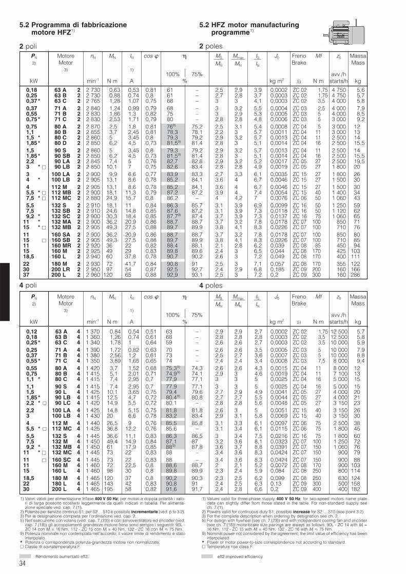
34
5.2 Programma di fabbricazionemotore HFZ1)
5.2 HFZ motor manufacturingprogramme1)
PN Motore nN MN IN cos MS Mmax IS J0 Freno Mf z0 Massa2) Motor MN MN IN Brake Mass
3) 1)100% 75% avv./h
kW min-1 N m A % kg m2 5) N m starts/h kg
2 poli 2 poles
Rendimento aumentato eff2. eff2 improved efficiency.
PN Motore nN MN IN cos MS Mmax IS J0 Freno Mf z0 Massa2) Motor MN MN IN Brake Mass
3) 1)100% 75% avv./h
kW min-1 N m A % kg m2 5) N m starts/h kg
4 poles4 poli
1) Valori validi per alimentazione trifase 400 V 50 Hz; per motori a doppia polarità i valo-ri di targa possono scostarsi leggermente da quelli indicati in tabella. Per alimenta-zione speciale ved. cap. 7.(1).
2) Potenze per servizio continuo S1; per S2 ... S10 è possibile incrementarle (ved. p.to 3.2).3) Per la designazione completa per l’ordinazione ved. cap. 2.5) Nell’esecuzione con volano (ved. cap. 7.(23)) e con servoventilatore ed encoder (ved.
cap. 7.(18)) gli accoppiamenti grandezze motore-freno sono sempre i seguenti: 90L -ZC 14 con Mf = 16 Nm, 112 - ZC 15 con Mf = 40 Nm, 132 - ZC 16 con Mf 75 Nm.
9) Potenza nominale non contemplata nell’accordo; il valore limite di rendimento è statointerpolato.
* Potenza o corrispondenza potenza-grandezza motore non normalizzate. Classe di sovratemperatura F.
1) Values valid for three-phase supply 400 V 50 Hz; for two-speed motors name platedata can slightly differ from those stated in the table. For non-standard supply seech. 7.(1).
2) Powers valid for continuous duty S1; possible increase for S2 ... S10 (see point 3.2).3) For the complete description when ordering by designation see ch. 2.5) For design with flywheel (see ch. 7.(23)) and with independent cooling fan and encoder
(see ch. 7.(18)) motor-brake size pairings are always as follows: 90L - ZC 14 with Mf =16 Nm, 112 - ZC 15 with Mf = 40 Nm, 132 - ZC 16 with Mf 75 Nm.
9) Nominal power not considered by the agreement; the limit value of efficiency has beeninterpolated.
* Power or motor power-to-size correspondence not according to standard. Temperature rise class F.
0,18 63 A 2 2 730 0,63 0,53 0,81 61 – 2,5 2,9 3,9 0,0002 ZC 02 0001,75 4 750 5,60,25 63 B 2 2 730 0,88 0,74 0,8 61 – 2,7 2,8 3,7 0,0003 ZC 02 0001,75 4 750 5,70,37 * 63 C 2 2 765 1,28 1,07 0,75 68 – 3 3 4,1 0,0003 ZC 02 0003,50 4 000 5,80,37 71 A 2 2 840 1,24 0,99 0,79 68 – 3 3,2 5,5 0,0004 ZC 03 0002,50 4 000 7,90,55 71 B 2 2 830 1,86 1,3 0,82 75 – 3 2,9 5,3 0,0005 ZC 03 0005,00 4 000 8,50,75 * 71 C 2 2 830 2,53 1,71 0,79 80 – 2,8 2,8 4,8 0,0006 ZC 03 0005,00 3 000 9,20,75 80 A 2 2 870 2,5 1,8 0,81 769) 75,2 2,5 3,1 5,4 0,0008 ZC 04 0005,00 3 000 121,1 80 B 2 2 855 3,7 2,45 0,81 78,3 78,1 2,2 3 5,7 0,0011 ZC 04 0011,00 3 000 131,5 * 80 C 2 2 860 5 3,45 0,8 79,3 79,2 2,9 3,2 5,7 0,0013 ZC 04 0011,00 2 500 141,85 * 80 D 2 2 850 6,2 4,5 0,73 81,59) 81,4 2,8 3 5,1 0,0014 ZC 04 0016 00 2 500 15,51,5 90 S 2 2 860 5 3,45 0,8 79,3 79,2 2,9 3,2 5,7 0,0013 ZC 04 0011 00 2 500 141,85 * 90 SB 2 2 850 6,2 4,5 0,73 81,59) 81,4 2,8 3 5,1 0,0014 ZC 04 0016 00 2 500 15,52,2 90 LA 2 2 845 7,4 5 0,76 82,7 82,8 2,9 3,2 5,2 0,0017 ZC 05 0027 00 2 500 19,53 * 90 LB 2 2 850 10,1 7 0,75 82,6 83,4 2,8 2,8 4,9 0,0019 ZC 05 00270 0 1 800 203 100 LA 2 2 900 9,9 6,6 0,77 83,9 83,3 2,7 3,3 6,1 0,0035 ZC 15 00270 0 1 800 264 * 100 LB 2 2 905 13,1 8,6 0,78 85,2 84,1 3,6 4 6,7 0,0046 ZC 15 00270 0 1 500 304 * 112 M 2 2 905 13,1 8,6 0,78 85,2 84,1 3,6 4 6,7 0,0046 ZC 15 0027 00 1 500 305,5 * 112 MB 2 2 900 18,1 11,3 0,79 87,2 87,2 3,9 4 7,4 0,0054 ZC 15 00400 0 1 400 347,5 * 112 MC 2 2 880 24,9 15,7 0,80 86,2 – 4 4,2 7 0,0076 ZC 06 00500 0 1 060 435,5 132 S 2 2 910 18,1 11 0,84 86,3 85,7 3,1 3,9 6,9 0,0099 ZC 16 01500 0 1 250 597,5 132 SB 2 2 910 24,6 14,8 0,85 87,6 87,2 3,1 3,9 7,3 0,0118 ZC 16 01500 0 1 120 629,2 * 132 SC 2 2 900 30,3 18,4 0,85 87,79) 87,4 3,7 3,9 7,3 0,0137 ZC 16 0175000 1 060 65
11 * 132 MA 2 2 900 36,2 20,9 0,86 88,7 88,7 3,7 3,2 7,8 0,0178 ZC 07 01000 0 1 850 7115 * 132 MB 2 2 905 49,3 27,5 0,88 89,7 89,9 3,8 4,1 8,3 0,0226 ZC 07 01000 0 1 710 7611 * 160 SA 2 2 900 36,2 20,9 0,86 88,7 88,7 3,7 3,2 7,8 0,0178 ZC 07 01000 0 1 850 8015 160 SB 2 2 905 49,3 27,5 0,88 89,7 89,9 3,8 4,1 8,3 0,0226 ZC 07 01000 0 1 710 8511 160 MR 2 2 920 36 22 0,82 88,4 88,1 2,1 2,8 6,2 0,039 ZC 08 01850 0 1 450 9415 160 M 2 2 925 49 29 0,83 89,8 89,6 2,4 3 6,5 0,044 ZC 08 01700 0 1 425 10318,5 160 L 2 2 940 60 37,8 0,78 90,7 90,2 2,6 3 7,2 0,049 ZC 08 01700 0 1 400 11122 180 M 2 2 930 72 41,7 0,84 90,8 91,0 2,5 3 7,1 0,057 ZC 08 01700 0 1 355 12230 200 LR 2 2 950 97 54 0,87 92,5 92,7 2,4 2,9 6,8 0,185 ZC 09 02000 0 1 160 16637 200 L 2 2 960 120 65 0,88 92,9 93,1 2,5 3 7,2 0,2 ZC 09 03000 0 1 160 286
0,12 63 A 4 1 370 0,84 0,54 0,51 63 – 2,9 2,9 2,7 0,0002 ZC 02 001,75 12 500 5,70,18 63 B 4 1 360 1,26 0,74 0,61 68 – 2,8 2,8 2,8 0,0003 ZC 02 003,50 12 500 5,80,25 * 63 C 4 1 340 1,78 1 0,64 59 – 2,6 2,6 2,7 0,0003 ZC 02 003,55 10 000 5,90,25 71 A 4 1 390 1,72 0,82 0,63 70 – 2,6 2,6 3,5 0,0005 ZC 03 005,75 10 000 7,90,37 71 B 4 1 380 2,56 1,2 0,61 73 – 2,5 2,7 3,6 0,0007 ZC 03 005,75 10 000 8,80,55 * 71 C 4 1 350 3,89 1,65 0,65 74 – 2,4 2,4 3,4 0,0008 ZC 03 007,55 8 000 9,40,55 80 A 4 1 420 3,7 1,52 0,68 75,39) 74,3 2,6 2,6 4,3 0,0015 ZC 04 011,75 8 000 120,75 80 B 4 1 415 5,1 2,01 0,71 74,99) 74,1 2,9 3 4,6 0,0019 ZC 04 011,75 7 100 131,1 * 80 C 4 1 415 7,4 2,95 0,7 77,9 77,1 3 3 5 0,0025 ZC 04 016,75 5 000 151,1 90 S 4 1 415 7,4 2,95 0,7 77,9 77,1 3 3 5 0,0025 ZC 04 016,75 5 000 151,5 90 L 4 1 425 10,1 3,65 0,75 79,4 79,6 2,7 2,9 4,9 0,0041 ZC 05 027,75 4 000 201,85 * 90 LB 4 1 415 12,5 4,7 0,72 80,49) 80,8 2,7 2,7 5,5 0,0044 ZC 05 027,75 4 000 212,2 * 90 LC 4 1 420 14,9 5,5 0,72 80,1 – 2,8 2,8 5,6 0,0048 ZC 05 027,75 3 150 232,2 100 LA 4 1 425 14,8 5,15 0,75 81,8 81,8 2,6 3 5 0,0051 ZC 15 040,75 3 150 263 100 LB 4 1 430 20 6,6 0,78 83,2 83,4 2,9 3,1 5,8 0,0069 ZC 15 040,75 3 150 304 112 M 4 1 440 26,5 9 0,76 85,5 85,8 3,1 3,3 6,1 0,0097 ZC 06 075,75 2 500 385,5 * 112 MC 4 1 425 36,8 12,2 0,76 85,6 – 3,1 3,4 6,1 0,0115 ZC 06 075,75 1 800 455,5 132 S 4 1 445 36,6 11,1 0,83 86,3 86,5 3 3,4 7,5 0,0216 ZC 16 075,75 1 800 607,5 132 M 4 1 450 49,4 14,9 0,84 87,1 87,5 3,2 3,6 8,1 0,0323 ZC 07 100,75 1 250 729,2 * 132 MB 4 1 450 61 17,9 0,85 889) 87,8 3,6 3,7 8,8 0,0391 ZC 07 150,75 1 060 76
11 * 132 MC 4 1 445 73 22 0,83 88 – 3,4 3,6 8,3 0,0424 ZC 07 150,75 10 900 7911 160 SC 4 1 445 73 22 0,83 88 – 3,4 3,6 8,3 0,0424 ZC 07 150,75 10 900 8811 160 M 4 1 460 72 22,5 0,8 88,6 88,7 2 2,1 5,2 0,0072 ZC 08 170,75 10 900 10315 160 L 4 1 460 98 30 0,8 89,8 89,9 2,3 2,4 5,9 0,084 ZC 08 250,75 10 800 11418,5 180 M 4 1 465 120 37 0,8 90,2 90,3 2,3 2,5 6,2 0,099 ZC 08 250,75 10 630 12422 180 L 4 1 465 143 42 0,83 90,8 91,5 2,4 2,5 6,3 0,13 ZC 09 300,75 10 500 15830 200 L 4 1 465 195 58 0,82 91,6 91,7 2,4 2,8 6,6 0,2 ZC 09 400,75 10 400 182
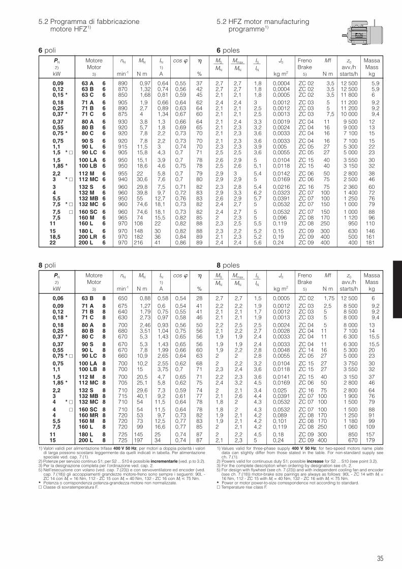
35
5.2 Programma di fabbricazionemotore HFZ1)
5.2 HFZ motor manufacturingprogramme1)
6 poli 6 poles
8 poli 8 poles
1) Valori validi per alimentazione trifase 400 V 50 Hz; per motori a doppia polarità i valoridi targa possono scostarsi leggermente da quelli indicati in tabella. Per alimentazionespeciale ved. cap. 7.(1).
2) Potenze per servizio continuo S1; per S2 ... S10 è possibile incrementarle (ved. p.to 3.2).3) Per la designazione completa per l’ordinazione ved. cap. 2.5) Nell’esecuzione con volano (ved. cap. 7.(23)) e con servoventilatore ed encoder (ved.
cap. 7.(18)) gli accoppiamenti grandezze motore-freno sono sempre i seguenti: 90L -ZC 14 con Mf = 16 Nm, 112 - ZC 15 con Mf = 40 Nm, 132 - ZC 16 con Mf 75 Nm.
* Potenza o corrispondenza potenza-grandezza motore non normalizzate. Classe di sovratemperatura F.
1) Values valid for three-phase supply 400 V 50 Hz; for two-speed motors name platedata can slightly differ from those stated in the table. For non-standard supply seech. 7.(1).
2) Powers valid for continuous duty S1; possible increase for S2 ... S10 (see point 3.2).3) For the complete description when ordering by designation see ch. 2.5) For design with flywheel (see ch. 7.(23)) and with independent cooling fan and encoder
(see ch. 7.(18)) motor-brake size pairings are always as follows: 90L - ZC 14 with Mf =16 Nm, 112 - ZC 15 with Mf = 40 Nm, 132 - ZC 16 with Mf 75 Nm.
* Power or motor power-to-size correspondence not according to standard. Temperature rise class F.
PN Motore nN MN IN cos MS Mmax IS J0 Freno M f z0 Massa2) Motor 1) MN MN IN Brake avv./h Mass
kW 3) min-1 N m A % kg m2 5) N m starts/h kg
0,09 63 A 6 890 0,97 0,64 0,55 37 2,7 2,7 1,8 0,0004 ZC 02 3,5 12 500 5,90,12 63 B 6 870 1,32 0,74 0,56 42 2,7 2,7 1,8 0,0004 ZC 02 3,5 12 500 5,90,15 * 63 C 6 850 1,68 0,81 0,59 45 2,1 2,1 1,8 0,0005 ZC 02 3,5 11 800 60,18 71 A 6 905 1,9 0,66 0,64 62 2,4 2,4 3 0,0012 ZC 03 5 11 200 9,20,25 71 B 6 890 2,7 0,89 0,63 64 2,1 2,1 2,5 0,0012 ZC 03 5 11 200 9,20,37 * 71 C 6 875 4 1,34 0,67 60 2,1 2,1 2,5 0,0013 ZC 03 7,5 10 000 9,40,37 80 A 6 930 3,8 1,3 0,66 64 2,1 2,4 3,3 0,0019 ZC 04 11 9 500 120,55 80 B 6 920 5,7 1,8 0,69 65 2,1 2,3 3,2 0,0024 ZC 04 16 9 000 130,75 * 80 C 6 920 7,8 2,2 0,73 70 2,1 2,3 3,6 0,0033 ZC 04 16 7 100 150,75 90 S 6 920 7,8 2,2 0,73 70 2,1 2,3 3,6 0,0033 ZC 04 16 7 100 151,1 90 L 6 915 11,5 3 0,74 70 2,3 2,3 3,9 0,005 ZC 05 27 5 300 221,5 * 90 LC 6 905 15,8 4,3 0,7 71 2,5 2,5 3,6 0,0055 ZC 05 27 5 000 231,5 100 LA 6 950 15,1 3,9 0,7 78 2,6 2,9 5 0,0104 ZC 15 40 3 550 301,85 * 100 LB 6 950 18,6 4,6 0,75 78 2,5 2,6 5,1 0,0118 ZC 15 40 3 150 322,2 112 M 6 955 22 5,8 0,7 79 2,9 3 5,4 0,0142 ZC 06 50 2 800 383 * 112 MC 6 940 30,6 7,6 0,7 80 2,9 2,9 5 0,0169 ZC 06 75 2 500 463 132 S 6 960 29,8 7,5 0,71 82 2,3 2,8 5,4 0,0216 ZC 16 75 2 360 604 132 M 6 960 39,8 9,7 0,72 83 2,9 3,3 6,2 0,0323 ZC 07 100 1 400 725,5 132 MB 6 950 55 12,7 0,76 83 2,6 2,9 5,7 0,0391 ZC 07 100 1 250 767,5 * 132 MC 6 960 74,6 18,1 0,73 82 2,4 2,7 5 0,0532 ZC 07 150 1 000 797,5 160 SC 6 960 74,6 18,1 0,73 82 2,4 2,7 5 0,0532 ZC 07 150 1 000 887,5 160 M 6 965 74 15,5 0,82 85 2 2,3 5 0,096 ZC 08 170 1 120 96
11 160 L 6 970 108 22 0,82 88 2,3 2,5 5,5 0,119 ZC 08 250 950 11015 180 L 6 970 148 30 0,82 88 2,3 2,2 5,2 0,15 ZC 09 300 630 14618,5 200 LR 6 970 182 36 0,84 89 2,1 2,3 5,2 0,19 ZC 09 400 500 16122 200 L 6 970 216 41 0,86 89 2,4 2,4 5,6 0,24 ZC 09 400 400 181
PN Motore nN MN IN cos MS Mmax IS J0 Freno M f z0 Massa2) Motor 1) MN MN IN Brake avv./h Mass
kW 3) min-1 N m A % kg m2 5) N m starts/h kg
0,06 63 B 8 650 0,88 0,58 0,54 28 2,7 2,7 1,5 0,0005 ZC 02 1,75 12 500 60,09 71 A 8 675 1,27 0,6 0,54 41 2,2 2,2 1,9 0,0012 ZC 03 2,5 8 500 9,20,12 71 B 8 640 1,79 0,75 0,55 41 2,1 2,1 1,7 0,0012 ZC 03 5 8 500 9,20,18 * 71 C 8 630 2,73 0,97 0,58 46 2,1 2,1 1,9 0,0013 ZC 03 5 8 000 9,40,18 80 A 8 700 2,46 0,93 0,56 50 2,2 2,5 2,5 0,0024 ZC 04 5 8 000 130,25 80 B 8 680 3,51 1,04 0,75 56 2,1 2,2 2,7 0,0028 ZC 04 11 7 100 140,37 * 80 C 8 670 5,3 1,43 0,65 56 1,9 1,9 2,4 0,0033 ZC 04 11 6 300 15,50,37 90 S 8 670 5,3 1,43 0,65 56 1,9 1,9 2,4 0,0033 ZC 04 11 6 300 15,50,55 90 L 8 670 7,8 1,99 0,66 60 1,9 2,2 2,8 0,0048 ZC 14 16 5 300 200,75 * 90 LC 8 660 10,9 2,65 0,64 63 2 2 2,8 0,0055 ZC 05 27 5 000 230,75 100 LA 8 700 10,2 2,55 0,62 68 2 2,2 3,2 0,0104 ZC 15 27 3 750 301,1 100 LB 8 700 15 3,75 0,7 71 2,3 2,4 3,6 0,0118 ZC 15 27 3 550 321,5 112 M 8 700 20,5 4,7 0,65 71 2,2 2,3 3,6 0,0141 ZC 15 40 3 150 371,85 * 112 MC 8 705 25,1 5,8 0,62 75 2,4 3,2 4,5 0,0169 ZC 06 50 2 800 462,2 132 S 8 710 29,6 7,3 0,59 74 2 2,1 3,4 0,025 ZC 16 75 2 800 643 132 MB 8 715 40,1 9,2 0,61 77 2,1 2,6 4,4 0,0391 ZC 07 100 1 900 764 * 132 MC 8 710 54 11,5 0,64 78 1,8 2 4,3 0,0532 ZC 07 100 1 500 794 160 SC 8 710 54 11,5 0,64 78 1,8 2 4,3 0,0532 ZC 07 100 1 500 884 160 MR 8 720 53 9,7 0,73 82 1,9 2,1 4,2 0,089 ZC 08 170 1 250 915,5 160 M 8 720 73 12,5 0,77 83 1,9 2,1 4,2 0,101 ZC 08 170 1 180 997,5 160 L 8 720 99 16,6 0,77 85 2 2,1 4,2 0,119 ZC 08 250 1 060 109
11 180 L 8 725 145 25 0,74 87 2 2,2 4,5 0,18 ZC 09 300 850 15715 200 L 8 725 197 34 0,74 87 2,1 2,3 5 0,24 ZC 09 400 670 179
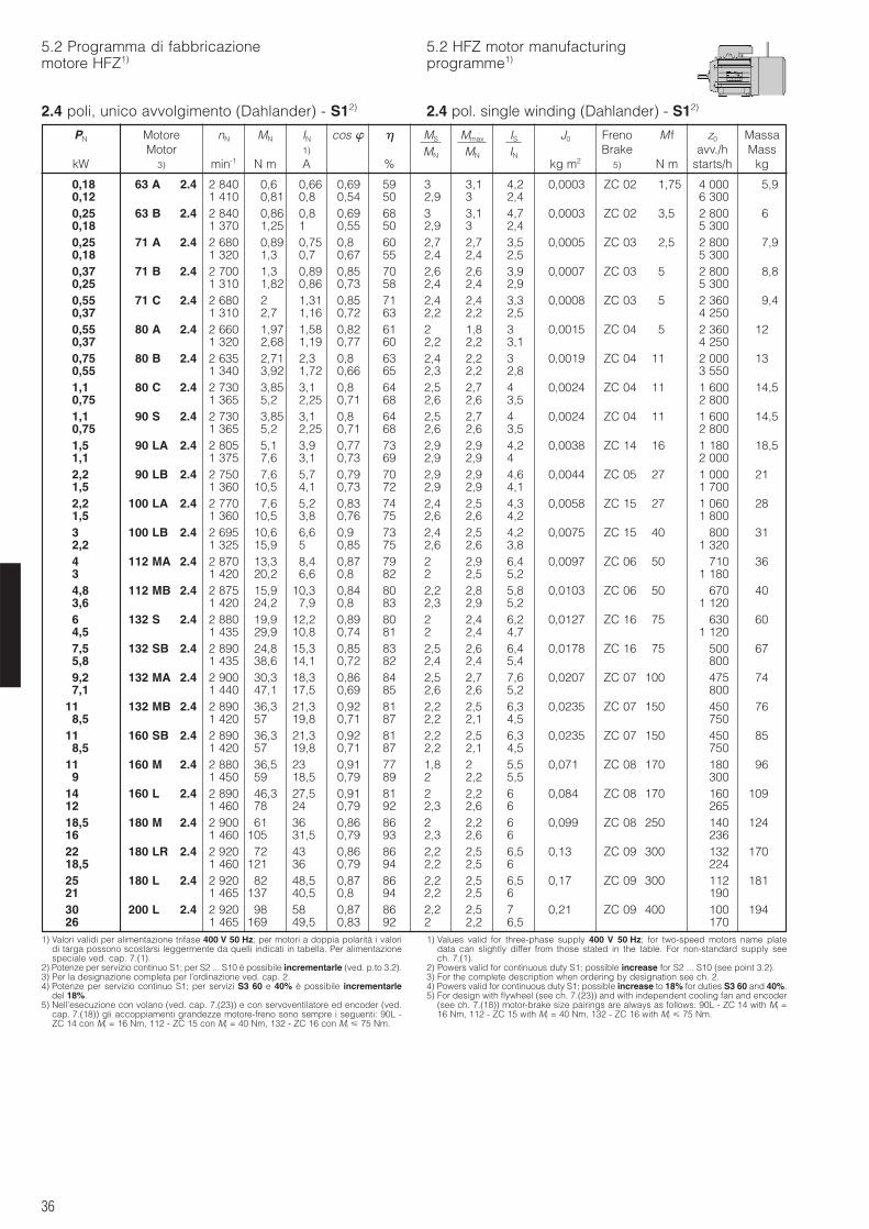
36
5.2 Programma di fabbricazionemotore HFZ1)
5.2 HFZ motor manufacturingprogramme1)
2.4 poli, unico avvolgimento (Dahlander) - S12)
1) Valori validi per alimentazione trifase 400 V 50 Hz; per motori a doppia polarità i valoridi targa possono scostarsi leggermente da quelli indicati in tabella. Per alimentazionespeciale ved. cap. 7.(1).
2) Potenze per servizio continuo S1; per S2 ... S10 è possibile incrementarle (ved. p.to 3.2).3) Per la designazione completa per l’ordinazione ved. cap. 2.4) Potenze per servizio continuo S1; per servizi S3 60 e 40% è possibile incrementarle
del 18%.5) Nell’esecuzione con volano (ved. cap. 7.(23)) e con servoventilatore ed encoder (ved.
cap. 7.(18)) gli accoppiamenti grandezze motore-freno sono sempre i seguenti: 90L -ZC 14 con Mf = 16 Nm, 112 - ZC 15 con Mf = 40 Nm, 132 - ZC 16 con Mf 75 Nm.
1) Values valid for three-phase supply 400 V 50 Hz; for two-speed motors name platedata can slightly differ from those stated in the table. For non-standard supply seech. 7.(1).
2) Powers valid for continuous duty S1; possible increase for S2 ... S10 (see point 3.2).3) For the complete description when ordering by designation see ch. 2.4) Powers valid for continuous duty S1; possible increase to 18% for duties S3 60 and 40%.5) For design with flywheel (see ch. 7.(23)) and with independent cooling fan and encoder
(see ch. 7.(18)) motor-brake size pairings are always as follows: 90L - ZC 14 with Mf =16 Nm, 112 - ZC 15 with Mf = 40 Nm, 132 - ZC 16 with Mf 75 Nm.
PN Motore nN MN IN cos MS Mmax IS J0 Freno M f z0 MassaMotor 1) MN MN IN Brake avv./h Mass
kW 3) min-1 N m A % kg m2 5) N m starts/h kg
0,18 63 A 2.4 2 840 0,6 0,66 0,69 59 3 3,1 4,2 0,0003 ZC 02 1,75 4 000 5,90,12 1 410 0,81 0,8 0,54 50 2,9 3 2,4 6 3000,25 63 B 2.4 2 840 0,86 0,8 0,69 68 3 3,1 4,7 0,0003 ZC 02 3,5 2 800 60,18 1 370 1,25 1 0,55 50 2,9 3 2,4 5 3000,25 71 A 2.4 2 680 0,89 0,75 0,8 60 2,7 2,7 3,5 0,0005 ZC 03 2,5 2 800 7,90,18 1 320 1,3 0,7 0,67 55 2,4 2,4 2,5 5 3000,37 71 B 2.4 2 700 1,3 0,89 0,85 70 2,6 2,6 3,9 0,0007 ZC 03 5 2 800 8,80,25 1 310 1,82 0,86 0,73 58 2,4 2,4 2,9 5 3000,55 71 C 2.4 2 680 2 1,31 0,85 71 2,4 2,4 3,3 0,0008 ZC 03 5 2 360 9,40,37 1 310 2,7 1,16 0,72 63 2,2 2,2 2,5 4 2500,55 80 A 2.4 2 660 1,97 1,58 0,82 61 2 1,8 3 0,0015 ZC 04 5 2 360 120,37 1 320 2,68 1,19 0,77 60 2,2 2,2 3,1 4 2500,75 80 B 2.4 2 635 2,71 2,3 0,8 63 2,4 2,2 3 0,0019 ZC 04 11 2 000 130,55 1 340 3,92 1,72 0,66 65 2,3 2,2 2,8 3 5501,1 80 C 2.4 2 730 3,85 3,1 0,8 64 2,5 2,7 4 0,0024 ZC 04 11 1 600 14,50,75 1 365 5,2 2,25 0,71 68 2,6 2,6 3,5 2 8001,1 90 S 2.4 2 730 3,85 3,1 0,8 64 2,5 2,7 4 0,0024 ZC 04 11 1 600 14,50,75 1 365 5,2 2,25 0,71 68 2,6 2,6 3,5 2 8001,5 90 LA 2.4 2 805 5,1 3,9 0,77 73 2,9 2,9 4,2 0,0038 ZC 14 16 1 180 18,51,1 1 375 7,6 3,1 0,73 69 2,9 2,9 4 2 0002,2 90 LB 2.4 2 750 7,6 5,7 0,79 70 2,9 2,9 4,6 0,0044 ZC 05 27 1 000 211,5 1 360 10,5 4,1 0,73 72 2,9 2,9 4,1 1 7002,2 100 LA 2.4 2 770 7,6 5,2 0,83 74 2,4 2,5 4,3 0,0058 ZC 15 27 1 060 281,5 1 360 10,5 3,8 0,76 75 2,6 2,6 4,2 1 8003 100 LB 2.4 2 695 10,6 6,6 0,9 73 2,4 2,5 4,2 0,0075 ZC 15 40 800 312,2 1 325 15,9 5 0,85 75 2,6 2,6 3,8 1 3204 112 MA 2.4 2 870 13,3 8,4 0,87 79 2 2,9 6,4 0,0097 ZC 06 50 710 363 1 420 20,2 6,6 0,8 82 2 2,5 5,2 1 1804,8 112 MB 2.4 2 875 15,9 10,3 0,84 80 2,2 2,8 5,8 0,0103 ZC 06 50 670 403,6 1 420 24,2 7,9 0,8 83 2,3 2,9 5,2 1 1206 132 S 2.4 2 880 19,9 12,2 0,89 80 2 2,4 6,2 0,0127 ZC 16 75 630 604,5 1 435 29,9 10,8 0,74 81 2 2,4 4,7 1 1207,5 132 SB 2.4 2 890 24,8 15,3 0,85 83 2,5 2,6 6,4 0,0178 ZC 16 75 500 675,8 1 435 38,6 14,1 0,72 82 2,4 2,4 5,4 8009,2 132 MA 2.4 2 900 30,3 18,3 0,86 84 2,5 2,7 7,6 0,0207 ZC 07 100 475 747,1 1 440 47,1 17,5 0,69 85 2,6 2,6 5,2 800
11 132 MB 2.4 2 890 36,3 21,3 0,92 81 2,2 2,5 6,3 0,0235 ZC 07 150 450 768,5 1 420 57 19,8 0,71 87 2,2 2,1 4,5 750
11 160 SB 2.4 2 890 36,3 21,3 0,92 81 2,2 2,5 6,3 0,0235 ZC 07 150 450 858,5 1 420 57 19,8 0,71 87 2,2 2,1 4,5 750
11 160 M 2.4 2 880 36,5 23 0,91 77 1,8 2 5,5 0,071 ZC 08 170 180 969 1 450 59 18,5 0,79 89 2 2,2 5,5 300
14 160 L 2.4 2 890 46,3 27,5 0,91 81 2 2,2 6 0,084 ZC 08 170 160 10912 1 460 78 24 0,79 92 2,3 2,6 6 26518,5 180 M 2.4 2 900 61 36 0,86 86 2 2,2 6 0,099 ZC 08 250 140 12416 1 460 105 31,5 0,79 93 2,3 2,6 6 23622 180 LR 2.4 2 920 72 43 0,86 86 2,2 2,5 6,5 0,13 ZC 09 300 132 17018,5 1 460 121 36 0,79 94 2,2 2,5 6 22425 180 L 2.4 2 920 82 48,5 0,87 86 2,2 2,5 6,5 0,17 ZC 09 300 112 18121 1 465 137 40,5 0,8 94 2,2 2,5 6 19030 200 L 2.4 2 920 98 58 0,87 86 2,2 2,5 7 0,21 ZC 09 400 100 19426 1 465 169 49,5 0,83 92 2 2,2 6,5 170
2.4 pol. single winding (Dahlander) - S12)
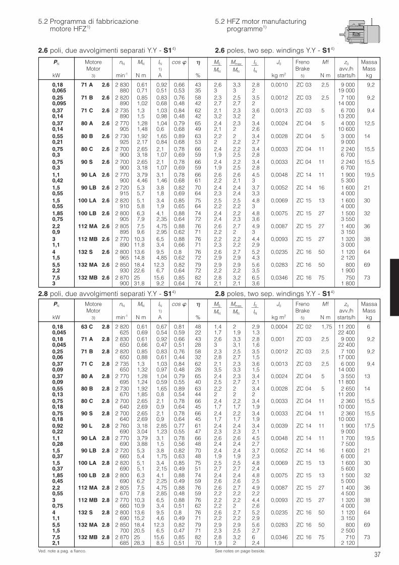
37
5.2 Programma di fabbricazionemotore HFZ1)
5.2 HFZ motor manufacturingprogramme1)
2.6 poli, due avvolgimenti separati Y.Y - S14)
2.8 poli, due avvolgimenti separati Y.Y - S14) 2.8 poles, two sep. windings Y.Y - S14)
Ved. note a pag. a fianco. See notes on page beside.
PN Motore nN MN IN cos MS Mmax IS J0 Freno M f z0 MassaMotor 1) MN MN IN Brake avv./h Mass
kW 3) min-1 N m A % kg m2 5) N m starts/h kg
PN Motore nN MN IN cos MS Mmax IS J0 Freno M f z0 MassaMotor 1) MN MN IN Brake avv./h Mass
kW 3) min-1 N m A % kg m2 5) N m starts/h kg
0,18 71 A 2.6 2 830 0,61 0,92 0,66 43 2,6 3,3 2,8 0,0010 ZC 03 2,5 9 000 9,20,065 880 0,71 0,51 0,53 35 3 3 2 19 0000,25 71 B 2.6 2 820 0,85 0,83 0,76 58 2,3 2,5 3,5 0,0012 ZC 03 2,5 7 100 9,20,095 890 1,02 0,68 0,48 42 2,7 2,7 2 14 0000,37 71 C 2.6 2 735 1,3 1,03 0,84 62 2,1 2,3 3,6 0,0013 ZC 03 5 6 700 9,40,14 890 1,5 0,98 0,48 42 3,2 3,2 2 13 2000,37 80 A 2.6 2 770 1,28 1,04 0,79 65 2,4 2,3 3,4 0,0024 ZC 04 5 4 000 12,50,14 905 1,48 0,6 0,68 49 2,1 2 2,6 10 6000,55 80 B 2.6 2 730 1,92 1,65 0,89 63 2,2 2 3,4 0,0028 ZC 04 5 3 000 140,21 925 2,17 0,84 0,68 53 2 2,2 2,7 9 0000,75 80 C 2.6 2 700 2,65 2,1 0,78 66 2,4 2,2 3,4 0,0033 ZC 04 11 2 240 15,50,3 900 3,18 1,07 0,69 59 1,9 2,5 2,8 6 7000,75 90 S 2.6 2 700 2,65 2,1 0,78 66 2,4 2,2 3,4 0,0033 ZC 04 11 2 240 15,50,3 900 3,18 1,07 0,69 59 1,9 2,5 2,8 6 7001,1 90 LA 2.6 2 770 3,79 3,1 0,78 66 2,6 2,6 4,5 0,0048 ZC 14 11 1 900 19,50,42 900 4,46 1,46 0,68 61 2,2 2,1 3 5 3001,5 90 LB 2.6 2 720 5,3 3,8 0,82 70 2,4 2,4 3,7 0,0052 ZC 14 16 1 600 210,55 915 5,7 1,8 0,69 64 2,3 2,4 3,3 4 0001,5 100 LA 2.6 2 820 5,1 3,4 0,85 75 2,5 2,5 4,8 0,0069 ZC 15 13 1 600 300,55 910 5,8 1,9 0,65 64 2,2 2,2 3 4 0001,85 100 LB 2.6 2 800 6,3 4,1 0,88 74 2,4 2,2 4,8 0,0075 ZC 15 27 1 500 320,75 905 7,9 2,35 0,64 72 2,4 2,3 3,6 3 5502,2 112 MA 2.6 2 805 7,5 4,75 0,88 76 2,6 2,7 4,9 0,0087 ZC 15 27 1 400 360,9 895 9,6 2,95 0,62 71 2,2 2 3 3 1503 112 MB 2.6 2 770 10,3 6,5 0,88 76 2,2 2,2 4,4 0,0093 ZC 15 27 1 320 381,1 890 11,8 3,4 0,66 71 2,3 2,2 2,9 3 0004 132 S 2.6 2 800 13,6 9,5 0,8 76 2,6 2,7 5,2 0,0235 ZC 16 50 1 120 641,5 965 14,8 4,85 0,62 72 2,9 2,9 4,3 2 1205,5 132 MA 2.6 2 850 18,4 12,3 0,82 79 2,9 2,9 5,6 0,0283 ZC 16 50 800 692,2 930 22,6 6,7 0,64 72 2,2 2,2 3,5 1 9007,5 132 MB 2.6 2 870 25 15,6 0,85 82 2,8 3,2 6,5 0,0346 ZC 16 75 750 733 900 31,8 9,2 0,64 74 2,1 2,1 3,6 1 800
0,18 63 C 2.8 2 820 0,61 0,67 0,81 48 1,4 2 2,9 0,0004 ZC 02 1,75 11 200 60,045 625 0,69 0,54 0,59 22 1,7 1,9 1,3 22 4000,18 71 A 2.8 2 830 0,61 0,92 0,66 43 2,6 3,3 2,8 0,001 ZC 03 2,5 9 000 9,20,045 650 0,66 0,47 0,51 28 3 3,1 1,6 22 4000,25 71 B 2.8 2 820 0,85 0,83 0,76 58 2,3 2,5 3,5 0,0012 ZC 03 2,5 7 100 9,20,06 650 0,88 0,61 0,44 32 2,8 2,7 1,5 17 0000,37 71 C 2.8 2 735 1,3 1,03 0,84 62 2,1 2,3 3,6 0,0013 ZC 03 2,5 6 000 9,40,09 650 1,32 0,97 0,48 28 3,5 3,3 1,5 14 0000,37 80 A 2.8 2 770 1,28 1,04 0,79 65 2,4 2,3 3,4 0,0024 ZC 04 5 3 550 130,09 695 1,24 0,59 0,55 40 2,5 2,7 2,1 11 8000,55 80 B 2.8 2 730 1,92 1,65 0,89 63 2,2 2 3,4 0,0028 ZC 04 5 2 650 140,13 670 1,85 0,8 0,54 44 2 2 2 11 2000,75 80 C 2.8 2 700 2,65 2,1 0,78 66 2,4 2,2 3,4 0,0033 ZC 04 11 2 360 15,50,18 640 2,69 0,9 0,64 45 1,7 1,7 1,9 10 0000,75 90 S 2.8 2 700 2,65 2,1 0,78 66 2,4 2,2 3,4 0,0033 ZC 04 11 2 360 15,50,18 640 2,69 0,9 0,64 45 1,7 1,7 1,9 10 0000,92 90 L 2.8 2 760 3,18 2,85 0,77 61 2,4 2,4 3,4 0,0039 ZC 14 11 1 900 17,50,22 690 3,04 1,23 0,55 47 2,3 2,3 2,1 9 0001,1 90 LA 2.8 2 770 3,79 3,1 0,78 66 2,6 2,6 4,5 0,0048 ZC 14 11 1 700 19,50,28 690 3,88 1,5 0,56 48 2,4 2,4 2,7 7 5001,5 90 LB 2.8 2 720 5,3 3,8 0,82 70 2,4 2,4 3,7 0,0052 ZC 14 16 1 600 210,37 660 5,4 1,75 0,63 48 1,9 1,9 2,3 6 0001,5 100 LA 2.8 2 820 5,1 3,4 0,85 75 2,5 2,5 4,8 0,0069 ZC 15 13 1 600 300,37 690 5,1 2,15 0,49 51 2,7 2,7 2,4 5 6001,85 100 LB 2.8 2 800 6,3 4,1 0,88 74 2,4 2,4 4,8 0,0075 ZC 15 13 1 500 320,45 690 6,2 2,25 0,49 59 2,6 2,6 2,5 5 0002,2 112 MA 2.8 2 805 7,5 4,75 0,88 76 2,6 2,7 4,9 0,0087 ZC 15 27 1 400 360,55 670 7,8 2,85 0,48 59 2,2 2,2 2,2 4 5003 112 MB 2.8 2 770 10,3 6,5 0,88 76 2,2 2,2 4,4 0,0093 ZC 15 27 1 320 380,75 660 10,9 3,4 0,51 62 2,2 2 2,6 4 0004 132 S 2.8 2 800 13,6 9,5 0,8 76 2,6 2,7 5,2 0,0235 ZC 16 50 1 120 641,1 690 15,2 4,6 0,49 71 2,2 2,2 2,9 3 1505,5 132 MA 2.8 2 850 18,4 12,3 0,82 79 2,9 2,9 5,6 0,0283 ZC 16 50 800 691,5 700 20,5 6,5 0,47 71 2,3 2,5 2,7 2 5007,5 132 MB 2.8 2 870 25 15,6 0,85 82 2,8 3,2 6 0,0346 ZC 16 75 710 732,1 685 28,3 8,5 0,51 70 1,9 2 2,4 2 120
2.6 poles, two sep. windings Y.Y - S14)
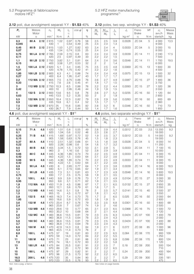
38
5.2 Programma di fabbricazionemotore HFZ1)
5.2 HFZ motor manufacturingprogramme1)
2.12 poli, due avvolgimenti separati Y.Y - S1.S3 40%
4.6 poli, due avvolgimenti separati Y.Y - S14) 4.6 poles, two separate windings Y.Y - S14)
Ved. note a pag. a fianco. See notes on page beside.
PN Motore nN MN IN cos MS Mmax IS J0 Freno M f z0 MassaMotor 1) MN MN IN Brake avv./h Mass
kW 3) min-1 N m A % kg m2 5) N m starts/h kg
PN Motore nN MN IN cos MS Mmax IS J0 Freno M f z0 MassaMotor 1) MN MN IN Brake avv./h Mass
kW 3) min-1 N m A % kg m2 5) N m starts/h kg
0,3 80 A 2.12 2 815 1,02 0,97 0,76 58 2,5 2,5 3,9 0,0028 ZC 04 5 4 000 13,50,045 430 1 0,54 0,49 25 2,4 2,4 1,4 9 0000,45 80 B 2.12 2 815 1,53 1,27 0,82 63 2,4 2,4 4 0,0033 ZC 04 5 3 000 150,07 435 1,54 0,74 0,55 25 2,4 2,4 1,5 8 0000,75 90 LA 2.12 2 765 2,59 2,15 0,8 63 2,4 2,4 3,9 0,0039 ZC 14 11 2 240 17,50,11 420 2,5 0,97 0,49 33 2,2 2,2 1,5 7 5001,1 90 LB 2.12 2 750 3,82 3,1 0,81 64 2,4 2,4 3,6 0,0048 ZC 14 11 1 700 19,50,15 400 3,58 1,27 0,53 32 2 2 1,4 6 0001,5 100 LA 2.12 2 820 5,1 3,4 0,85 75 2,5 2,5 4,8 0,0069 ZC 15 13 1 600 300,21 420 4,78 1,75 0,42 41 2,2 2,2 1,6 4 5001,85 100 LB 2.12 2 800 6,3 4,1 0,88 74 2,4 2,4 4,8 0,0075 ZC 15 13 1 500 320,27 400 6,4 1,95 0,47 43 1,7 1,7 1,7 4 0002,2 112 MA 2.12 2 805 7,5 4,75 0,88 76 2,6 2,7 4,9 0,0087 ZC 15 27 1 400 360,33 415 7,6 2,6 0,45 41 1,8 1,7 1,5 3 7503 112 MB 2.12 2 750 10,3 6,5 0,88 76 2,2 2,2 4,4 0,0093 ZC 15 27 1 320 380,42 400 10 2,95 0,46 44 1,9 1,9 1,5 3 5504 132 S 2.12 2 800 13,6 9,5 0,8 76 2,6 2,7 5,2 0,0235 ZC 16 50 1 120 640,63 445 13,5 5,2 0,35 50 2 2 1,9 2 8005,5 132 MA 2.12 2 850 18,4 12,3 0,82 79 2,9 2,9 5,6 0,0283 ZC 16 50 800 690,9 435 19,8 6,1 0,4 52 1,5 1,7 1,7 2 3607,5 132 MB 2.12 2 870 25 15,6 0,85 82 2,8 3,2 6 0,0346 ZC 16 50 710 731,2 430 26,7 7,9 0,44 50 1,4 1,7 1,6 1 800
0,15 71 A 4.6 1 420 1,01 0,8 0,55 49 2,8 2,9 4,4 0,0012 ZC 03 2,5 13 200 9,20,1 920 1,04 0,6 0,52 46 2,3 2,6 2,7 18 0000,25 71 B 4.6 1 415 1,69 0,97 0,72 52 1,9 2,5 3,7 0,0012 ZC 03 5 14 000 9,20,15 905 1,58 0,63 0,76 45 1,5 1,8 2,3 19 0000,37 80 A 4.6 1 410 2,51 1,32 0,66 61 1,5 1,8 3,8 0,0028 ZC 04 5 8 000 140,22 920 2,28 0,98 0,6 54 1,6 1,7 3,2 11 2000,5 80 B 4.6 1 455 3,34 1,5 0,72 53 2,1 2,9 5 0,0033 ZC 04 11 7 100 150,3 960 3 1,16 0,6 52 2,8 2,9 3,9 10 0000,66 80 C 4.6 1 445 4,36 1,85 0,74 70 2,2 2,5 4,9 0,0033 ZC 04 11 6 300 150,42 950 4,22 1,5 0,63 64 2,1 2,2 3,6 9 0000,66 90 S 4.6 1 445 4,36 1,85 0,74 70 2,2 2,5 4,9 0,0033 ZC 04 11 6 300 150,42 950 4,22 1,5 0,63 64 2,1 2,2 3,6 9 0000,9 90 LA 4.6 1 430 6 2,65 0,77 64 1,7 2,3 3,8 0,0039 ZC 14 16 6 300 18,50,6 940 6,1 2,15 0,65 62 1,9 2,1 3,4 9 0001,1 90 LB 4.6 1 435 7,3 3,1 0,81 63 1,7 2,3 4,9 0,0048 ZC 14 16 5 600 19,50,75 930 7,7 2,5 0,75 58 1,9 2,1 3,5 8 0001,5 100 L 4.6 1 440 9,9 3,9 0,76 73 1,7 2,3 4,9 0,0104 ZC 15 27 3 000 300,95 950 9,6 3,1 0,71 62 1,9 2,1 3,5 4 2501,8 112 MA 4.6 1 450 11,9 4,5 0,86 67 1,7 2,1 6,5 0,0132 ZC 15 27 2 650 351,2 950 12,1 3,6 0,79 61 1,6 1,7 5 3 5502,2 112 MB 4.6 1 440 14,6 5,1 0,8 78 2 2,5 5,7 0,0141 ZC 15 40 2 500 371,5 955 15 4,5 0,72 67 1,8 2,1 4,2 3 5502,8 132 S 4.6 1 465 18,3 7,4 0,73 75 1,7 2 6,5 0,025 ZC 16 50 2 000 641,85 950 18,6 5,9 0,72 63 1,6 1,9 5 2 8003,6 132 M 4.6 1 470 23,4 8,7 0,76 79 2,3 2,5 6,8 0,0301 ZC 16 50 1 800 682,4 965 23,8 7 0,67 74 1,9 2 4,6 2 5004,5 132 MB 4.6 1 450 29,6 13 0,77 65 2,1 2,3 6,5 0,0368 ZC 16 75 1 500 723 950 30,2 10 0,68 64 2 2,1 4,4 2 1205,6 132 MC 4.6 1 460 36,6 13,5 0,81 79 2,3 2,5 6,3 0,0424 ZC 07 100 1 400 793,7 960 36,8 11,5 0,64 78 2,3 2,4 4,3 2 0005,6 160 SC 4.6 1 460 36,6 13,5 0,81 79 2,3 2,5 6,3 0,0424 ZC 07 100 1 400 883,7 960 36,8 11,5 0,64 78 2,3 2,4 4,3 2 0006,6 160 M 4.6 1 470 42,9 14,3 0,8 84 1,9 2,1 6 0,072 ZC 08 85 1 000 964,4 965 43,5 11,4 0,73 76 2 2 5 1 4008,8 160 L 4.6 1 475 57 19 0,81 83 2,2 2,5 6,5 0,084 ZC 08 170 900 1096 970 59 14,3 0,72 84 2,2 2,2 5,5 1 250
11 180 M 4.6 1 475 71 23 0,81 86 2,2 2,5 6,8 0,099 ZC 08 170 800 1247,5 970 74 18,1 0,72 83 2,2 2,2 5,8 1 120
13 180 LR 4.6 1 475 84 25,5 0,81 91 2,2 2,5 7 0,18 ZC 09 200 500 1549 970 89 20 0,72 90 2,2 2,2 6,5 710
15 180 L 4.6 1 475 97 29 0,82 91 2 2,2 7 0,24 ZC 09 200 400 16410 970 98 21,5 0,73 92 2,2 2,2 6,5 56018,5 200 L 4.6 1 475 120 35 0,84 90 2 2,2 7 0,29 ZC 09 300 335 18112,5 970 123 25,5 0,76 93 2,2 2,2 6,5 475
2.12 poles, two sep. windings Y.Y - S1.S3 40%
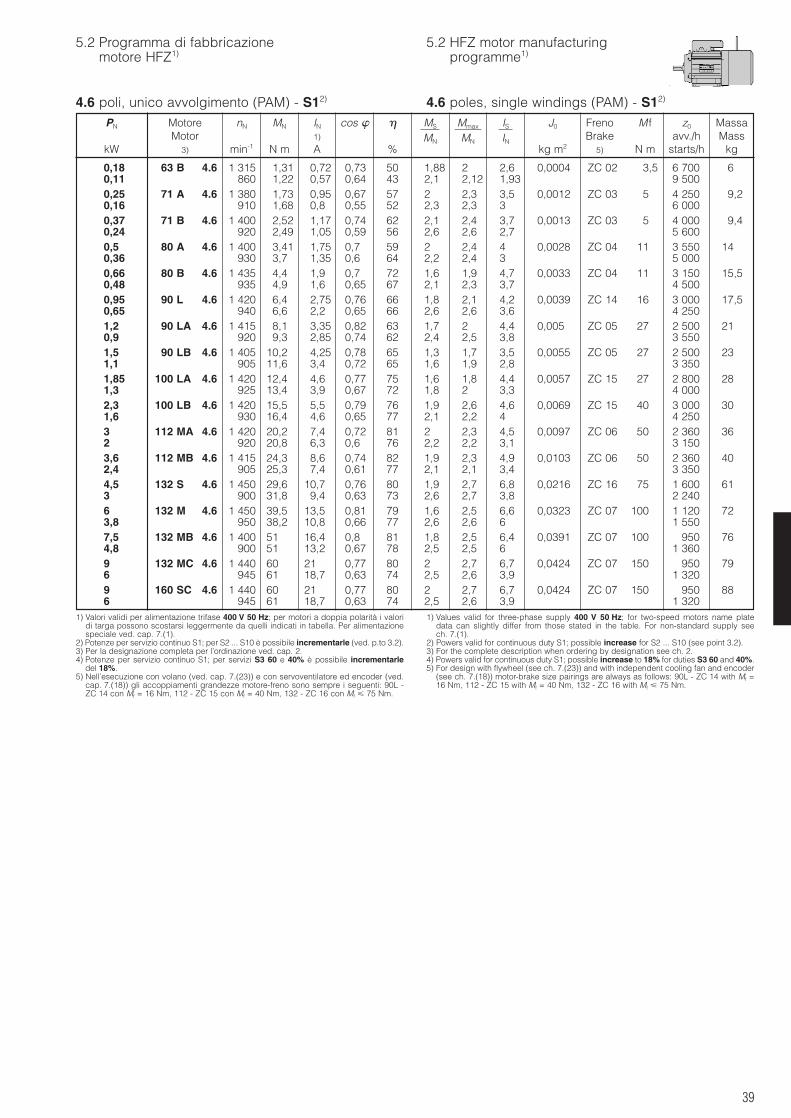
39
5.2 Programma di fabbricazionemotore HFZ1)
5.2 HFZ motor manufacturingprogramme1)
4.6 poli, unico avvolgimento (PAM) - S12)
1) Valori validi per alimentazione trifase 400 V 50 Hz; per motori a doppia polarità i valoridi targa possono scostarsi leggermente da quelli indicati in tabella. Per alimentazionespeciale ved. cap. 7.(1).
2) Potenze per servizio continuo S1; per S2 ... S10 è possibile incrementarle (ved. p.to 3.2).3) Per la designazione completa per l’ordinazione ved. cap. 2.4) Potenze per servizio continuo S1; per servizi S3 60 e 40% è possibile incrementarle
del 18%.5) Nell’esecuzione con volano (ved. cap. 7.(23)) e con servoventilatore ed encoder (ved.
cap. 7.(18)) gli accoppiamenti grandezze motore-freno sono sempre i seguenti: 90L -ZC 14 con Mf = 16 Nm, 112 - ZC 15 con Mf = 40 Nm, 132 - ZC 16 con Mf 75 Nm.
1) Values valid for three-phase supply 400 V 50 Hz; for two-speed motors name platedata can slightly differ from those stated in the table. For non-standard supply seech. 7.(1).
2) Powers valid for continuous duty S1; possible increase for S2 ... S10 (see point 3.2).3) For the complete description when ordering by designation see ch. 2.4) Powers valid for continuous duty S1; possible increase to 18% for duties S3 60 and 40%.5) For design with flywheel (see ch. 7.(23)) and with independent cooling fan and encoder
(see ch. 7.(18)) motor-brake size pairings are always as follows: 90L - ZC 14 with Mf =16 Nm, 112 - ZC 15 with Mf = 40 Nm, 132 - ZC 16 with Mf 75 Nm.
PN Motore nN MN IN cos MS Mmax IS J0 Freno M f z0 MassaMotor 1) MN MN IN Brake avv./h Mass
kW 3) min-1 N m A % kg m2 5) N m starts/h kg
0,18 63 B 4.6 1 315 1,31 0,72 0,73 50 1,88 2 2,6 0,0004 ZC 02 3,5 6 700 60,11 860 1,22 0,57 0,64 43 2,1 2,12 1,93 9 5000,25 71 A 4.6 1 380 1,73 0,95 0,67 57 2 2,3 3,5 0,0012 ZC 03 5 4 250 9,20,16 910 1,68 0,8 0,55 52 2,3 2,3 3 6 0000,37 71 B 4.6 1 400 2,52 1,17 0,74 62 2,1 2,4 3,7 0,0013 ZC 03 5 4 000 9,40,24 920 2,49 1,05 0,59 56 2,6 2,6 2,7 5 6000,5 80 A 4.6 1 400 3,41 1,75 0,7 59 2 2,4 4 0,0028 ZC 04 11 3 550 140,36 930 3,7 1,35 0,6 64 2,2 2,4 3 5 0000,66 80 B 4.6 1 435 4,4 1,9 0,7 72 1,6 1,9 4,7 0,0033 ZC 04 11 3 150 15,50,48 935 4,9 1,6 0,65 67 2,1 2,3 3,7 4 5000,95 90 L 4.6 1 420 6,4 2,75 0,76 66 1,8 2,1 4,2 0,0039 ZC 14 16 3 000 17,50,65 940 6,6 2,2 0,65 66 2,6 2,6 3,6 4 2501,2 90 LA 4.6 1 415 8,1 3,35 0,82 63 1,7 2 4,4 0,005 ZC 05 27 2 500 210,9 920 9,3 2,85 0,74 62 2,4 2,5 3,8 3 5501,5 90 LB 4.6 1 405 10,2 4,25 0,78 65 1,3 1,7 3,5 0,0055 ZC 05 27 2 500 231,1 905 11,6 3,4 0,72 65 1,6 1,9 2,8 3 3501,85 100 LA 4.6 1 420 12,4 4,6 0,77 75 1,6 1,8 4,4 0,0057 ZC 15 27 2 800 281,3 925 13,4 3,9 0,67 72 1,8 2 3,3 4 0002,3 100 LB 4.6 1 420 15,5 5,5 0,79 76 1,9 2,6 4,6 0,0069 ZC 15 40 3 000 301,6 930 16,4 4,6 0,65 77 2,1 2,2 4 4 2503 112 MA 4.6 1 420 20,2 7,4 0,72 81 2 2,3 4,5 0,0097 ZC 06 50 2 360 362 920 20,8 6,3 0,6 76 2,2 2,2 3,1 3 1503,6 112 MB 4.6 1 415 24,3 8,6 0,74 82 1,9 2,3 4,9 0,0103 ZC 06 50 2 360 402,4 905 25,3 7,4 0,61 77 2,1 2,1 3,4 3 3504,5 132 S 4.6 1 450 29,6 10,7 0,76 80 1,9 2,7 6,8 0,0216 ZC 16 75 1 600 613 900 31,8 9,4 0,63 73 2,6 2,7 3,8 2 2406 132 M 4.6 1 450 39,5 13,5 0,81 79 1,6 2,5 6,6 0,0323 ZC 07 100 1 120 723,8 950 38,2 10,8 0,66 77 2,6 2,6 6 1 5507,5 132 MB 4.6 1 400 51 16,4 0,8 81 1,8 2,5 6,4 0,0391 ZC 07 100 950 764,8 900 51 13,2 0,67 78 2,5 2,5 6 1 3609 132 MC 4.6 1 440 60 21 0,77 80 2 2,7 6,7 0,0424 ZC 07 150 950 796 945 61 18,7 0,63 74 2,5 2,6 3,9 1 3209 160 SC 4.6 1 440 60 21 0,77 80 2 2,7 6,7 0,0424 ZC 07 150 950 886 945 61 18,7 0,63 74 2,5 2,6 3,9 1 320
4.6 poles, single windings (PAM) - S12)
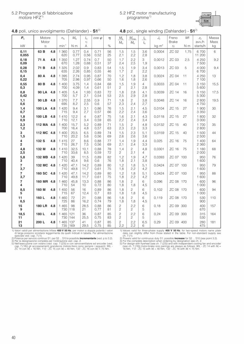
40
5.2 Programma di fabbricazionemotore HFZ1)
5.2 HFZ motor manufacturingprogramme1)
4.8 poli, unico avvolgimento (Dahlander) - S12)
1) Valori validi per alimentazione trifase 400 V 50 Hz; per motori a doppia polarità i valoridi targa possono scostarsi leggermente da quelli indicati in tabella. Per alimentazionespeciale ved. cap. 7.(1).
2) Potenze per servizio continuo S1; per S2 ... S10 è possibile incrementarle (ved. p.to 3.2).3) Per la designazione completa per l’ordinazione ved. cap. 2.5) Nell’esecuzione con volano (ved. cap. 7.(23)) e con servoventilatore ed encoder (ved.
cap. 7.(18)) gli accoppiamenti grandezze motore-freno sono sempre i seguenti: 90L -ZC 14 con Mf = 16 Nm, 112 - ZC 15 con Mf = 40 Nm, 132 - ZC 16 con Mf 75 Nm.
1) Values valid for three-phase supply 400 V 50 Hz; for two-speed motors name platedata can slightly differ from those stated in the table. For non-standard supply seech. 7.(1).
2) Powers valid for continuous duty S1; possible increase for S2 ... S10 (see point 3.2).3) For the complete description when ordering by designation see ch. 2.5) For design with flywheel (see ch. 7.(23)) and with independent cooling fan and encoder
(see ch. 7.(18)) motor-brake size pairings are always as follows: 90L - ZC 14 with Mf =16 Nm, 112 - ZC 15 with Mf = 40 Nm, 132 - ZC 16 with Mf 75 Nm.
PN Motore nN MN IN cos MS Mmax IS J0 Freno M f z0 MassaMotor 1) MN MN IN Brake avv./h Mass
kW 3) min-1 N m A % kg m2 5) N m starts/h kg
0,11 63 B 4.8 1 360 0,77 0,4 0,71 56 1,5 1,5 3,6 0,0004 ZC 02 1,75 6 700 60,055 620 0,77 0,56 0,52 25 2,1 2,2 2,8 11 2000,18 71 A 4.8 1 350 1,27 0,74 0,7 50 1,7 2,2 3 0,0012 ZC 03 2,5 4 250 9,20,09 670 1,28 0,68 0,51 37 2,4 2,5 1,9 7 5000,28 71 B 4.8 1 325 2,02 0,9 0,83 54 1,5 1,9 3,4 0,0013 ZC 03 5 4 000 9,40,15 635 2,26 0,85 0,55 46 1,7 2 2,2 6 7000,4 80 A 4.8 1 395 2,74 0,95 0,87 70 1,2 1,8 3,8 0,0024 ZC 04 11 4 250 130,22 705 2,98 0,97 0,66 50 1,6 1,8 2,6 7 1000,55 80 B 4.8 1 400 3,75 1,4 0,84 68 1,5 1,9 4 0,0033 ZC 04 11 3 150 15,50,3 700 4,09 1,4 0,61 51 2 2,1 2,8 5 6000,8 90 LA 4.8 1 405 5,4 1,93 0,83 72 1,8 2,8 4,1 0,0039 ZC 14 16 3 150 17,50,42 700 5,7 2,1 0,54 53 2,5 2,9 2,8 5 3001,1 90 LB 4.8 1 370 7,7 2,55 0,9 71 1,8 2 3,8 0,0048 ZC 14 16 2 800 19,50,6 695 8,2 2,5 0,6 57 2,3 2,4 2,7 4 7501,4 100 LA 4.8 1 420 9,4 3,1 0,86 76 1,5 2,1 4,5 0,0104 ZC 15 27 1 900 300,7 715 9,4 2,7 0,57 66 2,2 2,4 3,6 3 3501,8 100 LB 4.8 1 410 12,2 4 0,87 75 1,6 2,1 4,3 0,0118 ZC 15 27 1 800 320,9 710 12,1 3,4 0,59 65 2,2 2,4 3,4 3 0002,3 112 MA 4.8 1 400 15,7 5,2 0,89 71 1,5 2 4,8 0,0132 ZC 15 40 1 700 351,2 700 16,4 4,8 0,57 63 2,3 2,3 3,3 2 8003 112 MC 4.8 1 400 20,5 6,5 0,89 74 1,5 2,3 5,1 0,0159 ZC 15 40 1 500 441,5 710 20,2 5,6 0,56 69 2,6 2,6 3,6 2 5004 132 S 4.8 1 415 27 8,6 0,88 77 1,4 1,9 4,4 0,025 ZC 16 75 1 400 642 715 26,7 7,5 0,56 69 2,1 2,4 3,3 2 3604,8 132 M 4.8 1 410 32,5 10,1 0,88 78 1,4 2 4,8 0,0301 ZC 16 75 1 180 682,5 710 33,6 8,5 0,59 72 2 2,1 4 2 0005,8 132 MB 4.8 1 420 39 11,5 0,89 82 1,2 1,9 4,7 0,0393 ZC 07 100 950 763 710 40,4 9,6 0,6 76 1,8 2,1 3,8 1 6007 132 MC 4.8 1 420 47,1 14,2 0,89 80 1,2 1,8 5,1 0,0424 ZC 07 100 950 793,7 710 49,8 11,7 0,61 75 1,8 2,2 4,2 1 6007 160 SC 4.8 1 420 47,1 14,2 0,89 80 1,2 1,8 5,1 0,0424 ZC 07 100 950 883,7 710 49,8 11,7 0,61 75 1,8 2,2 4,2 1 6007 160 MR 4.8 1 460 45,8 13,3 0,88 86 1,8 2 6 0,096 ZC 08 170 600 964 710 54 10 0,72 80 1,8 1,8 4,5 1 0008,5 160 M 4.8 1 450 56 16 0,89 86 1,8 2 6 0,102 ZC 08 170 600 945 715 67 12,4 0,7 83 1,8 1,8 4,5 1 000
11 160 L 4.8 1 460 72 21 0,88 86 1,8 2 6 0,119 ZC 08 170 530 1106,5 725 86 16,2 0,74 79 1,8 1,8 4,5 900
15 180 LR 4.8 1 465 98 28,5 0,88 86 2 2,2 6 0,18 ZC 09 300 400 1579 730 118 21 0,77 81 2 2 5 670
18,5 180 L 4.8 1 465 121 36 0,87 85 2 2,2 6 0,24 ZC 09 300 315 16411 730 144 25,5 0,75 83 2 2 5 53021 200 L 4.8 1 465 137 41 0,87 85 2 2,2 6,5 0,29 ZC 09 400 280 18113 735 169 29,5 0,75 85 2,2 2,2 6 475
4.8 pol., single winding (Dahlander) - S12)
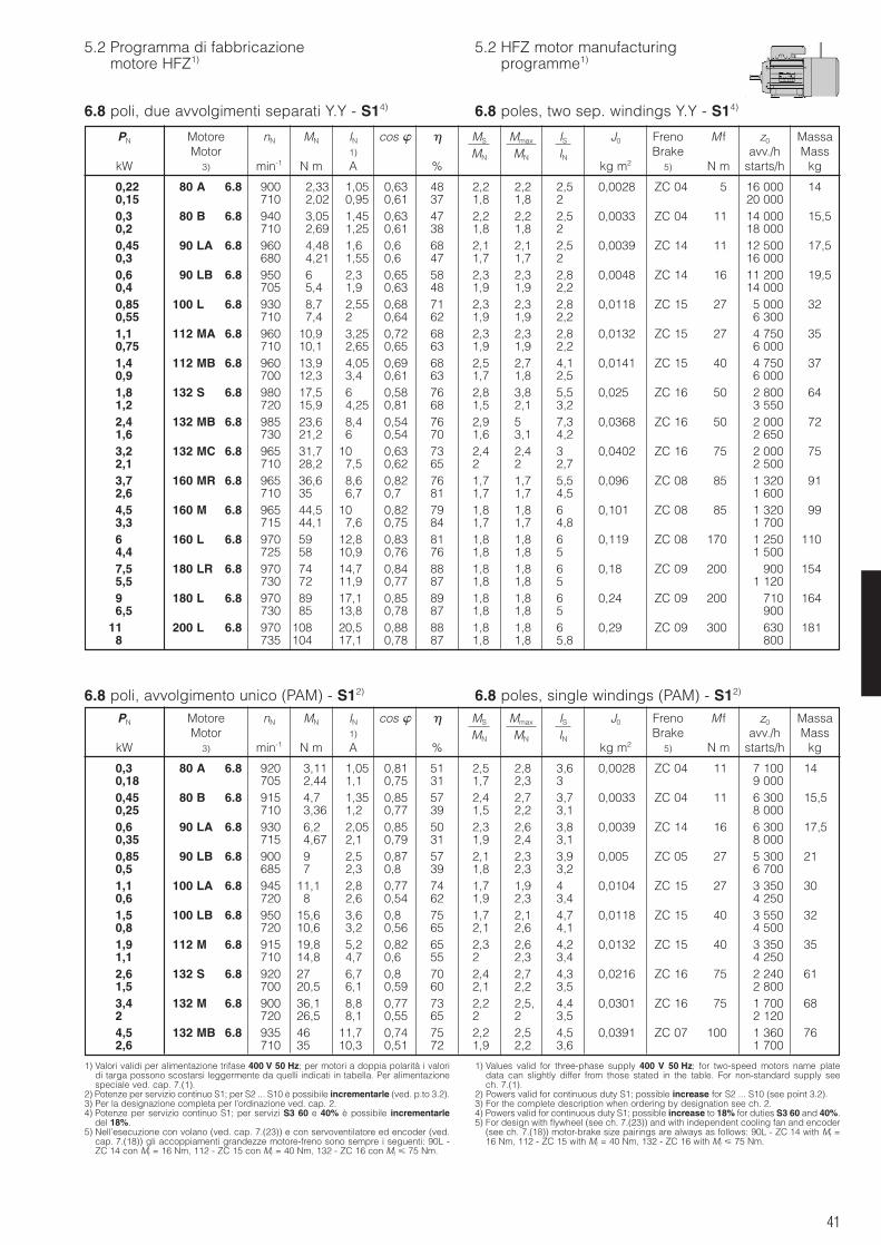
41
5.2 Programma di fabbricazionemotore HFZ1)
5.2 HFZ motor manufacturingprogramme1)
6.8 poli, due avvolgimenti separati Y.Y - S14)
6.8 poli, avvolgimento unico (PAM) - S12) 6.8 poles, single windings (PAM) - S12)
1) Valori validi per alimentazione trifase 400 V 50 Hz; per motori a doppia polarità i valoridi targa possono scostarsi leggermente da quelli indicati in tabella. Per alimentazionespeciale ved. cap. 7.(1).
2) Potenze per servizio continuo S1; per S2 ... S10 è possibile incrementarle (ved. p.to 3.2).3) Per la designazione completa per l’ordinazione ved. cap. 2.4) Potenze per servizio continuo S1; per servizi S3 60 e 40% è possibile incrementarle
del 18%.5) Nell’esecuzione con volano (ved. cap. 7.(23)) e con servoventilatore ed encoder (ved.
cap. 7.(18)) gli accoppiamenti grandezze motore-freno sono sempre i seguenti: 90L -ZC 14 con Mf = 16 Nm, 112 - ZC 15 con Mf = 40 Nm, 132 - ZC 16 con Mf 75 Nm.
1) Values valid for three-phase supply 400 V 50 Hz; for two-speed motors name platedata can slightly differ from those stated in the table. For non-standard supply seech. 7.(1).
2) Powers valid for continuous duty S1; possible increase for S2 ... S10 (see point 3.2).3) For the complete description when ordering by designation see ch. 2.4) Powers valid for continuous duty S1; possible increase to 18% for duties S3 60 and 40%.5) For design with flywheel (see ch. 7.(23)) and with independent cooling fan and encoder
(see ch. 7.(18)) motor-brake size pairings are always as follows: 90L - ZC 14 with Mf =16 Nm, 112 - ZC 15 with Mf = 40 Nm, 132 - ZC 16 with Mf 75 Nm.
PN Motore nN MN IN cos MS Mmax IS J0 Freno M f z0 MassaMotor 1) MN MN IN Brake avv./h Mass
kW 3) min-1 N m A % kg m2 5) N m starts/h kg
PN Motore nN MN IN cos MS Mmax IS J0 Freno M f z0 MassaMotor 1) MN MN IN Brake avv./h Mass
kW 3) min-1 N m A % kg m2 5) N m starts/h kg
0,22 80 A 6.8 900 2,33 1,05 0,63 48 2,2 2,2 2,5 0,0028 ZC 04 5 16 000 140,15 710 2,02 0,95 0,61 37 1,8 1,8 2 20 0000,3 80 B 6.8 940 3,05 1,45 0,63 47 2,2 2,2 2,5 0,0033 ZC 04 11 14 000 15,50,2 710 2,69 1,25 0,61 38 1,8 1,8 2 18 0000,45 90 LA 6.8 960 4,48 1,6 0,6 68 2,1 2,1 2,5 0,0039 ZC 14 11 12 500 17,50,3 680 4,21 1,55 0,6 47 1,7 1,7 2 16 0000,6 90 LB 6.8 950 6 2,3 0,65 58 2,3 2,3 2,8 0,0048 ZC 14 16 11 200 19,50,4 705 5,4 1,9 0,63 48 1,9 1,9 2,2 14 0000,85 100 L 6.8 930 8,7 2,55 0,68 71 2,3 2,3 2,8 0,0118 ZC 15 27 5 000 320,55 710 7,4 2 0,64 62 1,9 1,9 2,2 6 3001,1 112 MA 6.8 960 10,9 3,25 0,72 68 2,3 2,3 2,8 0,0132 ZC 15 27 4 750 350,75 710 10,1 2,65 0,65 63 1,9 1,9 2,2 6 0001,4 112 MB 6.8 960 13,9 4,05 0,69 68 2,5 2,7 4,1 0,0141 ZC 15 40 4 750 370,9 700 12,3 3,4 0,61 63 1,7 1,8 2,5 6 0001,8 132 S 6.8 980 17,5 6 0,58 76 2,8 3,8 5,5 0,025 ZC 16 50 2 800 641,2 720 15,9 4,25 0,81 68 1,5 2,1 3,2 3 5502,4 132 MB 6.8 985 23,6 8,4 0,54 76 2,9 5 7,3 0,0368 ZC 16 50 2 000 721,6 730 21,2 6 0,54 70 1,6 3,1 4,2 2 6503,2 132 MC 6.8 965 31,7 10 0,63 73 2,4 2,4 3 0,0402 ZC 16 75 2 000 752,1 710 28,2 7,5 0,62 65 2 2 2,7 2 5003,7 160 MR 6.8 965 36,6 8,6 0,82 76 1,7 1,7 5,5 0,096 ZC 08 85 1 320 912,6 710 35 6,7 0,7 81 1,7 1,7 4,5 1 6004,5 160 M 6.8 965 44,5 10 0,82 79 1,8 1,8 6 0,101 ZC 08 85 1 320 993,3 715 44,1 7,6 0,75 84 1,7 1,7 4,8 1 7006 160 L 6.8 970 59 12,8 0,83 81 1,8 1,8 6 0,119 ZC 08 170 1 250 1104,4 725 58 10,9 0,76 76 1,8 1,8 5 1 5007,5 180 LR 6.8 970 74 14,7 0,84 88 1,8 1,8 6 0,18 ZC 09 200 900 1545,5 730 72 11,9 0,77 87 1,8 1,8 5 1 1209 180 L 6.8 970 89 17,1 0,85 89 1,8 1,8 6 0,24 ZC 09 200 710 1646,5 730 85 13,8 0,78 87 1,8 1,8 5 900
11 200 L 6.8 970 108 20,5 0,88 88 1,8 1,8 6 0,29 ZC 09 300 630 1818 735 104 17,1 0,78 87 1,8 1,8 5,8 800
0,3 80 A 6.8 920 3,11 1,05 0,81 51 2,5 2,8 3,6 0,0028 ZC 04 11 7 100 140,18 705 2,44 1,1 0,75 31 1,7 2,3 3 9 0000,45 80 B 6.8 915 4,7 1,35 0,85 57 2,4 2,7 3,7 0,0033 ZC 04 11 6 300 15,50,25 710 3,36 1,2 0,77 39 1,5 2,2 3,1 8 0000,6 90 LA 6.8 930 6,2 2,05 0,85 50 2,3 2,6 3,8 0,0039 ZC 14 16 6 300 17,50,35 715 4,67 2,1 0,79 31 1,9 2,4 3,1 8 0000,85 90 LB 6.8 900 9 2,5 0,87 57 2,1 2,3 3,9 0,005 ZC 05 27 5 300 210,5 685 7 2,3 0,8 39 1,8 2,3 3,2 6 7001,1 100 LA 6.8 945 11,1 2,8 0,77 74 1,7 1,9 4 0,0104 ZC 15 27 3 350 300,6 720 8 2,6 0,54 62 1,9 2,3 3,4 4 2501,5 100 LB 6.8 950 15,6 3,6 0,8 75 1,7 2,1 4,7 0,0118 ZC 15 40 3 550 320,8 720 10,6 3,2 0,56 65 2,1 2,6 4,1 4 5001,9 112 M 6.8 915 19,8 5,2 0,82 65 2,3 2,6 4,2 0,0132 ZC 15 40 3 350 351,1 710 14,8 4,7 0,6 55 2 2,3 3,4 4 2502,6 132 S 6.8 920 27 6,7 0,8 70 2,4 2,7 4,3 0,0216 ZC 16 75 2 240 611,5 700 20,5 6,1 0,59 60 2,1 2,2 3,5 2 8003,4 132 M 6.8 900 36,1 8,8 0,77 73 2,2 2,5, 4,4 0,0301 ZC 16 75 1 700 682 720 26,5 8,1 0,55 65 2 2 3,5 2 1204,5 132 MB 6.8 935 46 11,7 0,74 75 2,2 2,5 4,5 0,0391 ZC 07 100 1 360 762,6 710 35 10,3 0,51 72 1,9 2,2 3,6 1 700
6.8 poles, two sep. windings Y.Y - S14)
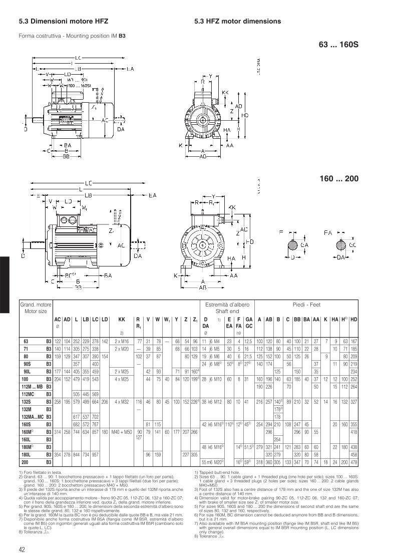
42
5.3 Dimensioni motore HFZ 5.3 HFZ motor dimensions
1) Foro filettato in testa.2) Grand. 63 ... 90: 1 bocchettone pressacavo + 1 tappo filettato (un foro per parte);
grand. 100 ... 160S: 1 bocchettone pressacavo + 3 tappi filettati (due fori per parte);grand. 160 ... 200: 2 bocchettoni pressacavo M40 + M50.
3) Il piede del 132S riporta anche un interasse di 178 mm e quello del 132M riporta ancheun’interasse di 140 mm.
4) Quota valida per accoppiamento motore - freno 90-ZC 05, 112-ZC 06, 132 e 160-ZC 07;con il freno della grandezza inferiore ved. quota Z1 della grand. motore inferiore.
5) Per grand. 90S, 160S e 180 ... 200, le dimensioni della seconda estremità d’albero sonole stesse delle grand. 80, 132 e 160 rispettivamente.
6) Per la grand. 160M la quota BC non è più deducibile dalle quote BB e B, ma vale 21 mm.7) Disponibile anche forma costruttiva IM B5A (flangia come IM B5R, estremità d’albero
come IM B5) con ingombri generali uguali alla forma costruttiva IM B5R (cambiano solole quote L, LC).
8) Tolleranza -oo,5.
1) Tapped butt-end hole.2) Sizes 63 ... 90: 1 cable gland + 1 threaded plug (one hole per side); sizes 100 ... 160S:
1 cable gland + 3 threaded plugs (2 holes per side); sizes 160 ... 200: 2 cable glandsM40+M50.
3) Foot of 132S also has a centre distance of 178 mm and the one of size 132M has alsoa centre distance of 140 mm.
4) Dimension valid for motor-brake pairing 90-ZC 05, 112-ZC 06, 132 and 160-ZC 07;with brake of smaller size see Z1 of smaller motor size.
5) For sizes 90S, 160S and 180 ... 200 the dimensions of second shaft end are the sameof sizes 80, 132 and 160, respectively.
6) For size 160M, BC dimension cannot be deduced anymore from BB and B dimensions,but it is 21 mm.
7) Also available with IM B5A mounting position (flange like IM B5R, shaft end like IM B5)with general overall dimensions equal to IM B5R mounting position (L, LC dimensionsonly change).
8) Tolerance -oo,5.
Forma costruttiva - Mounting position IM B3
63 ... 160S
160 ... 200
Grand. motoreMotor size
Estremità d’alberoShaft end
Piedi - Feet
AC AD L LB LC LD KK R1 V W W1 Y Z Z1 D 1) E F GA A AB B C BB BA AA K HA H8) HDØ R1 DA EA FA GC
2) Ø h9
63 B3 122 104 252 229 278 142 2 x M16 77 31 78 – 66 54 96 11 j6 M4 23 4 12,5 100 120 80 40 100 21 27 7 9 63 16771 B3 140 114 305 275 338 2 x M20 – 39 85 68 66 103 14 j6 M5 30 5 16 112 138 90 45 110 22 28 10 71 18580 B3 159 129 347 307 390 154 102 37 87 80 129 19 j6 M6 40 6 21,5 125 152 100 50 125 26 9 80 20990S B3 357 400 – 24 j6 M85) 505) 85) 275) 140 174 56 37 11 90 21990L B3 177 144 405 355 459 2 x M25 42 93 71 91 1604) 125 150 35 234
100 B3 204 152 479 419 543 4 x M25 44 75 40 84 120 1994) 28 j6 M10 60 8 31 160 196 140 63 185 40 37 12 12 100 252112M ... MB B3 190 226 70 50 15 112 264112MC B3 505 445 569132S B3 258 195 579 499 664 206 4 x M32 116 46 80 45 100 152 2264) 38 k6 M12 80 10 41 216 257 1403) 89 210 32 52 14 16 132 327132M B3 – 1783)
132MA...MC B3 617 537 702 178160S B3 682 572 767 81 115 42 k6 M165) 1105) 125) 455) 254 294 210 108 247 45 20 160 355160M6) B3 314 258 744 634 857 180 M40 + M50 90 79 141 60 177 207 266 296 296 90 55 418160L B3 127 254180M6) B3 48 k6 M165) 145) 51,55) 279 321 241 121 283 60 60 22 180 438180L B3 354 278 844 734 957 96 159 227 305 320 279 320 80 58 458200 B3 55 m6 M205) 165) 595) 318 360 305 133 347 70 74 18 24 200 478
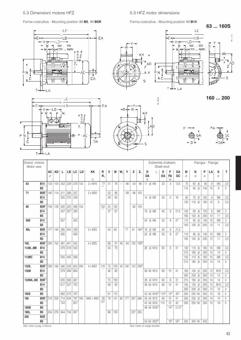
43
5.3 Dimensioni motore HFZ 5.3 HFZ motor dimensions
Forma costruttiva - Mounting position IM B5, IM B5R Forma costruttiva - Mounting position IM B14
Ved. note a pag. a fianco. See notes on page beside.
160 ... 200
Grand. motoreMotor size
AC AD L LB LC LD KK R1 V W W1 Y Z Z1 D 1) E F GA M N P LA S TØ R1 DA EA FA GC Ø Ø Ø Ø
2) Ø h9
Estremità d’alberoShaft end
Flangia - Flange
63 B14 122 104 252 229 278 142 2 x M16 77 31 78 – 66 54 96 11 j6 M4 23 4 12,5 75 60 j6 90 8 M5 2,5B5
–115 95 j6 140 10 9 3
71 B5R7) 140 114 311 288 337 2 x M20 52 98 68 66 103B14 305 275 338 39 85 14 j6 M5 30 5 16 85 70 j6 105 8 M6 2,5B5 130 110 j6 160 10 9 3,5
80 B5R7) 159 129 355 325 388 154 102 55 105 80 129B14 347 307 390
–37 87 19 j6 M6 40 6 21,5 100 80 j6 120 8 M6 3
B5 165 130 j6 200 12 11 3,590S B14 357 400 24 j6 M8 50 8 27 115 95 j6 140 10 M8 3
B5 165 130 j6 200 12 11 3,590L B5R 177 144 395 355 439 2 x M25 42 93 71 91 1604) 19 j6 M6 40 6 21,5
B14 405 459 24 j6 M8 50 8 27 115 95 j6 140 10 M8 3B5 165 130 j6 200 12 11 3,5
100, B5R7) 204 152 491 441 545 4 x M25 66 97 40 84 120 1994)
112M...MB B14 479 419 543 44 75 28 j6 M10 60 8 31 130 110 j6 160 10 M8 3,5B5 215 180 j6 250 14 14 4
112MC B14 505 445 569 130 110 j6 160 10 M8 3,5B5 215 180 j6 250 14 14 4
132S, B5R7) 258 195 588 528 653 206 4 x M32 116 75 109 45 100 152 2264)
132M B14 579 499 664–
46 80 38 k6 M12 80 10 41 165 130 j6 200 13 M10 3,5B5 265 230 j6 300 14 14 4
132MA...MC B5R7) 626 566 691 75 109 28 j6 M10 60 8 31 215 180 j6 250 14 14 4B14 617 537 702 46 80 38 k6 M12 80 10 41 165 130 j6 200 13 M10 3,5B5 265 230 j6 300 14 14 4
160S B5 682 572 767 81 115 42 k6 M165) 1105) 125) 455) 300 250 h6 350 15 18 5160 B5R7) 314 258 714 634 797 180 M40 + M50 90 79 141 60 177 207 266 38 k6 M125) 805) 105) 415) 265 230 j6 300 14 14 4
B5 744 857 127 42 k6 M165) 1105) 125) 455) 300 250 h6 350 15 18 5180M B5 48 k6 M165) 145) 51,55)
180L B5 354 278 844 734 957 96 159 227 305200 B5R
B5 55 m6 M205) 165) 595) 350 300 h6 400
63 ... 160S
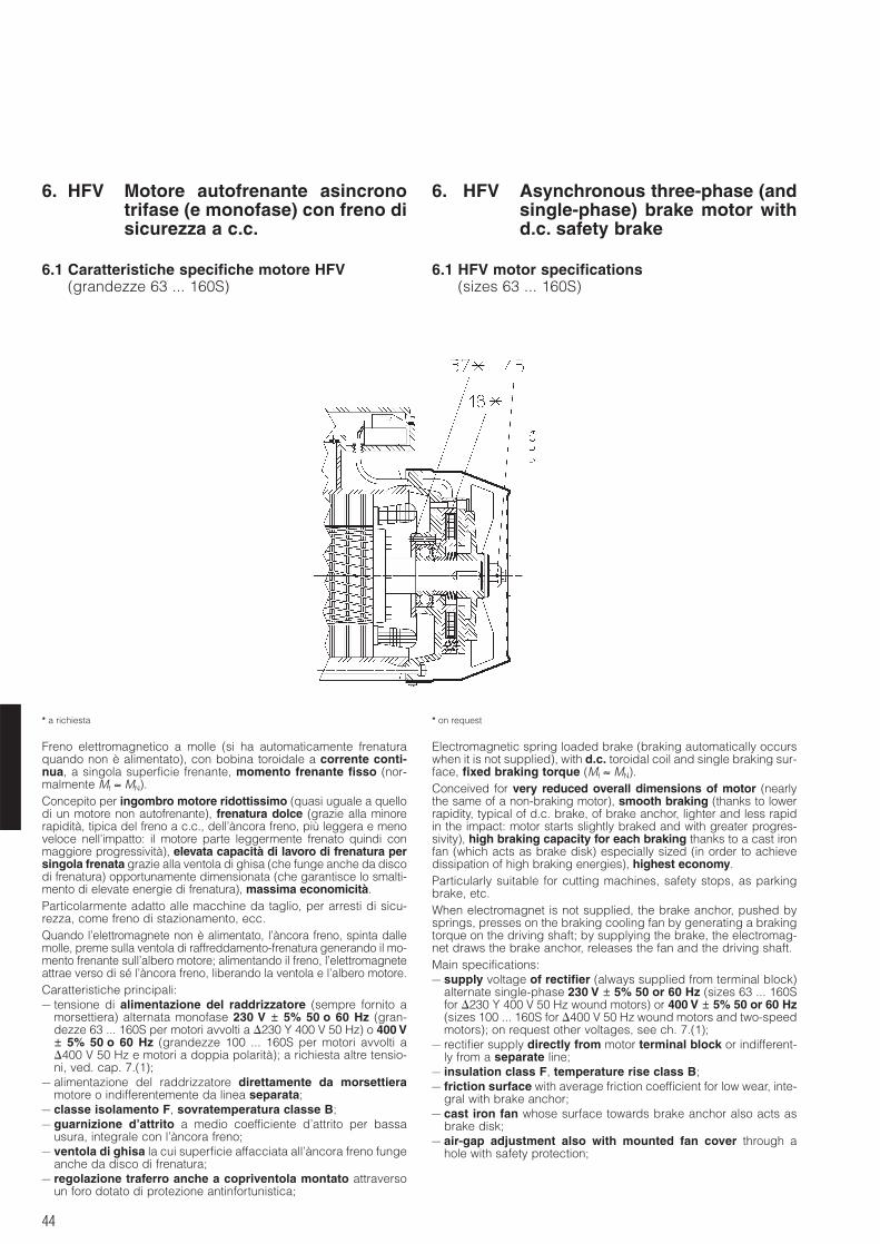
44
6. HFV Motore autofrenante asincronotrifase (e monofase) con freno disicurezza a c.c.
6. HFV Asynchronous three-phase (andsingle-phase) brake motor withd.c. safety brake
6.1 Caratteristiche specifiche motore HFV(grandezze 63 ... 160S)
6.1 HFV motor specifications(sizes 63 ... 160S)
* a richiesta * on request
Freno elettromagnetico a molle (si ha automaticamente frenaturaquando non è alimentato), con bobina toroidale a corrente conti-nua, a singola superficie frenante, momento frenante fisso (nor-malmente Mf ≈ MN).Concepito per ingombro motore ridottissimo (quasi uguale a quellodi un motore non autofrenante), frenatura dolce (grazie alla minorerapidità, tipica del freno a c.c., dell’àncora freno, più leggera e menoveloce nell’impatto: il motore parte leggermente frenato quindi conmaggiore progressività), elevata capacità di lavoro di frenatura persingola frenata grazie alla ventola di ghisa (che funge anche da discodi frenatura) opportunamente dimensionata (che garantisce lo smalti-mento di elevate energie di frenatura), massima economicità.Particolarmente adatto alle macchine da taglio, per arresti di sicu-rezza, come freno di stazionamento, ecc.Quando l’elettromagnete non è alimentato, l’àncora freno, spinta dallemolle, preme sulla ventola di raffreddamento-frenatura generando il mo-mento frenante sull’albero motore; alimentando il freno, l’elettromagneteattrae verso di sé l’àncora freno, liberando la ventola e l’albero motore.Caratteristiche principali:– tensione di alimentazione del raddrizzatore (sempre fornito a
morsettiera) alternata monofase 230 V ± 5% 50 o 60 Hz (gran-dezze 63 ... 160S per motori avvolti a 230 Y 400 V 50 Hz) o 400 V± 5% 50 o 60 Hz (grandezze 100 ... 160S per motori avvolti a400 V 50 Hz e motori a doppia polarità); a richiesta altre tensio-ni, ved. cap. 7.(1);
– alimentazione del raddrizzatore direttamente da morsettieramotore o indifferentemente da linea separata;
– classe isolamento F, sovratemperatura classe B;– guarnizione d’attrito a medio coefficiente d’attrito per bassa
usura, integrale con l’àncora freno;– ventola di ghisa la cui superficie affacciata all’àncora freno funge
anche da disco di frenatura;– regolazione traferro anche a copriventola montato attraverso
un foro dotato di protezione antinfortunistica;
Electromagnetic spring loaded brake (braking automatically occurswhen it is not supplied), with d.c. toroidal coil and single braking sur-face, fixed braking torque (Mf ≈ MN).Conceived for very reduced overall dimensions of motor (nearlythe same of a non-braking motor), smooth braking (thanks to lowerrapidity, typical of d.c. brake, of brake anchor, lighter and less rapidin the impact: motor starts slightly braked and with greater progres-sivity), high braking capacity for each braking thanks to a cast ironfan (which acts as brake disk) especially sized (in order to achievedissipation of high braking energies), highest economy.Particularly suitable for cutting machines, safety stops, as parkingbrake, etc.When electromagnet is not supplied, the brake anchor, pushed bysprings, presses on the braking cooling fan by generating a brakingtorque on the driving shaft; by supplying the brake, the electromag-net draws the brake anchor, releases the fan and the driving shaft.Main specifications:– supply voltage of rectifier (always supplied from terminal block)
alternate single-phase 230 V ± 5% 50 or 60 Hz (sizes 63 ... 160Sfor 230 Y 400 V 50 Hz wound motors) or 400 V ± 5% 50 or 60 Hz(sizes 100 ... 160S for 400 V 50 Hz wound motors and two-speedmotors); on request other voltages, see ch. 7.(1);
– rectifier supply directly from motor terminal block or indifferent-ly from a separate line;
– insulation class F, temperature rise class B;– friction surface with average friction coefficient for low wear, inte-
gral with brake anchor;– cast iron fan whose surface towards brake anchor also acts as
brake disk;– air-gap adjustment also with mounted fan cover through a
hole with safety protection;
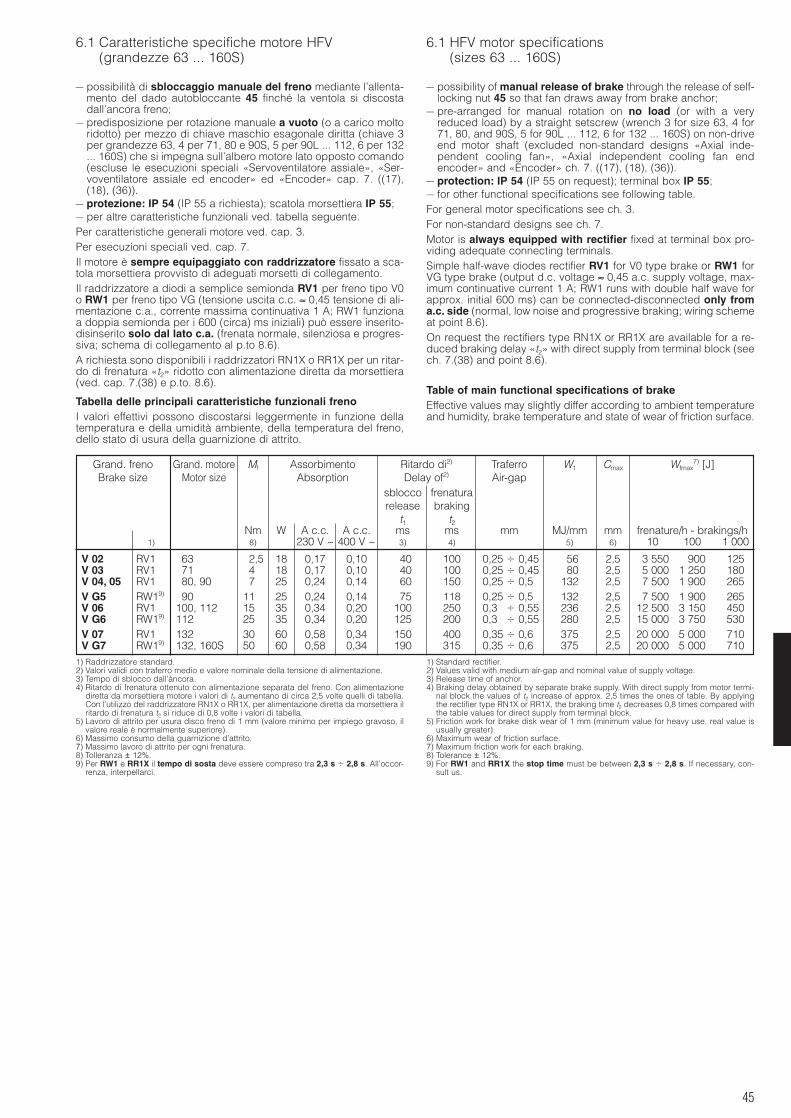
45
6.1 Caratteristiche specifiche motore HFV(grandezze 63 ... 160S)
6.1 HFV motor specifications(sizes 63 ... 160S)
– possibilità di sbloccaggio manuale del freno mediante l’allenta-mento del dado autobloccante 45 finché la ventola si discostadall’ancora freno;
– predisposizione per rotazione manuale a vuoto (o a carico moltoridotto) per mezzo di chiave maschio esagonale diritta (chiave 3per grandezze 63, 4 per 71, 80 e 90S, 5 per 90L ... 112, 6 per 132... 160S) che si impegna sull’albero motore lato opposto comando(escluse le esecuzioni speciali «Servoventilatore assiale», «Ser-voventilatore assiale ed encoder» ed «Encoder» cap. 7. ((17),(18), (36)).
– protezione: IP 54 (IP 55 a richiesta); scatola morsettiera IP 55;– per altre caratteristiche funzionali ved. tabella seguente.Per caratteristiche generali motore ved. cap. 3.Per esecuzioni speciali ved. cap. 7.Il motore è sempre equipaggiato con raddrizzatore fissato a sca-tola morsettiera provvisto di adeguati morsetti di collegamento.Il raddrizzatore a diodi a semplice semionda RV1 per freno tipo V0o RW1 per freno tipo VG (tensione uscita c.c. ≈ 0,45 tensione di ali-mentazione c.a., corrente massima continuativa 1 A; RW1 funzionaa doppia semionda per i 600 (circa) ms iniziali) può essere inserito-disinserito solo dal lato c.a. (frenata normale, silenziosa e progres-siva; schema di collegamento al p.to 8.6).A richiesta sono disponibili i raddrizzatori RN1X o RR1X per un ritar-do di frenatura «t2» ridotto con alimentazione diretta da morsettiera(ved. cap. 7.(38) e p.to. 8.6).
Tabella delle principali caratteristiche funzionali frenoI valori effettivi possono discostarsi leggermente in funzione dellatemperatura e della umidità ambiente, della temperatura del freno,dello stato di usura della guarnizione di attrito.
– possibility of manual release of brake through the release of self-locking nut 45 so that fan draws away from brake anchor;
– pre-arranged for manual rotation on no load (or with a veryreduced load) by a straight setscrew (wrench 3 for size 63, 4 for71, 80, and 90S, 5 for 90L ... 112, 6 for 132 ... 160S) on non-driveend motor shaft (excluded non-standard designs «Axial inde-pendent cooling fan», «Axial independent cooling fan endencoder» and «Encoder» ch. 7. ((17), (18), (36)).
– protection: IP 54 (IP 55 on request); terminal box IP 55;– for other functional specifications see following table.For general motor specifications see ch. 3.For non-standard designs see ch. 7.Motor is always equipped with rectifier fixed at terminal box pro-viding adequate connecting terminals.Simple half-wave diodes rectifier RV1 for V0 type brake or RW1 forVG type brake (output d.c. voltage ≈ 0,45 a.c. supply voltage, max-imum continuative current 1 A; RW1 runs with double half wave forapprox. initial 600 ms) can be connected-disconnected only froma.c. side (normal, low noise and progressive braking; wiring schemeat point 8.6).On request the rectifiers type RN1X or RR1X are available for a re-duced braking delay «t2» with direct supply from terminal block (seech. 7.(38) and point 8.6).
Table of main functional specifications of brakeEffective values may slightly differ according to ambient temperatureand humidity, brake temperature and state of wear of friction surface.
Grand. freno Grand. motore Mf Assorbimento Ritardo di2) Traferro W1 Cmax Wfmax7) [J]
Brake size Motor size Absorption Delay of2) Air-gapsblocco frenaturarelease braking
t1 t2Nm W A c.c. A c.c. ms ms mm MJ/mm mm frenature/h - brakings/h
1) 8) 230 V ~ 400 V ~ 3) 4) 5) 6) 10 100 1 000
V 02 RV1 63 2,5 18 0,17 0,10 40 100 0,25 0,45 56 2,5 3 550 900 125V 03 RV1 71 4 18 0,17 0,10 40 100 0,25 0,45 80 2,5 5 000 1 250 180V 04, 05 RV1 80, 90 7 25 0,24 0,14 60 150 0,25 0,5 132 2,5 7 500 1 900 265V G5 RW19) 90 11 25 0,24 0,14 75 118 0,25 0,5 132 2,5 7 500 1 900 265V 06 RV1 100, 112 15 35 0,34 0,20 100 250 0,3 0,55 236 2,5 12 500 3 150 450V G6 RW19) 112 25 35 0,34 0,20 125 200 0,3 0,55 280 2,5 15 000 3 750 530V 07 RV1 132 30 60 0,58 0,34 150 400 0,35 0,6 375 2,5 20 000 5 000 710V G7 RW19) 132, 160S 50 60 0,58 0,34 190 315 0,35 0,6 375 2,5 20 000 5 000 710
1) Raddrizzatore standard.2) Valori validi con traferro medio e valore nominale della tensione di alimentazione.3) Tempo di sblocco dall’àncora.4) Ritardo di frenatura ottenuto con alimentazione separata del freno. Con alimentazione
diretta da morsettiera motore i valori di t2 aumentano di circa 2,5 volte quelli di tabella.Con l’utilizzo del raddrizzatore RN1X o RR1X, per alimentazione diretta da morsettiera ilritardo di frenatura t2 si riduce di 0,8 volte i valori di tabella.
5) Lavoro di attrito per usura disco freno di 1 mm (valore minimo per impiego gravoso, ilvalore reale è normalmente superiore).
6) Massimo consumo della guarnizione d’attrito.7) Massimo lavoro di attrito per ogni frenatura.8) Tolleranza ± 12%.9) Per RW1 e RR1X il tempo di sosta deve essere compreso tra 2,3 s 2,8 s. All’occor-
renza, interpellarci.
1) Standard rectifier.2) Values valid with medium air-gap and nominal value of supply voltage.3) Release time of anchor.4) Braking delay obtained by separate brake supply. With direct supply from motor termi-
nal block the values of t2 increase of approx. 2,5 times the ones of table. By applyingthe rectifier type RN1X or RR1X, the braking time t2 decreases 0,8 times compared withthe table values for direct supply from terminal block.
5) Friction work for brake disk wear of 1 mm (minimum value for heavy use, real value isusually greater).
6) Maximum wear of friction surface.7) Maximum friction work for each braking.8) Tolerance ± 12%.9) For RW1 and RR1X the stop time must be between 2,3 s 2,8 s. If necessary, con-
sult us.
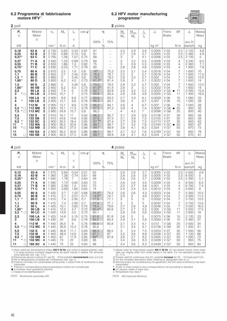
46
6.2 Programma di fabbricazionemotore HFV1)
6.2 HFV motor manufacturingprogramme1)
2 poli 2 poles
Rendimento aumentato eff2. eff2 improved efficiency.
4 poles4 poli
1) Valori validi per alimentazione trifase 400 V 50 Hz; per motori a doppia polarità i valo-ri di targa possono scostarsi leggermente da quelli indicati in tabella. Per alimenta-zione speciale ved. cap. 7.(1).
2) Potenze per servizio continuo S1; per S2 ... S10 è possibile incrementarle (ved. p.to 3.2).3) Per la designazione completa per l’ordinazione ved. cap. 2.9) Potenza nominale non contemplata nell’accordo; il valore limite di rendimento è stato
interpolato.* Potenza o corrispondenza potenza-grandezza motore non normalizzate. A richiesta, freno grandezza inferiore. Classe di sovratemperatura F.
1) Values valid for three-phase supply 400 V 50 Hz; for two-speed motors name platedata can slightly differ from those stated in the table. For non-standard supply seech. 7.(1).
2) Powers valid for continuous duty S1; possible increase for S2 ... S10 (see point 3.2).3) For the complete description when ordering by designation see ch. 2.9) Nominal power not considered by the agreement; the limit value of efficiency has been
interpolated.* Power or motor power-to-size correspondence not according to standard. On request, brake of lower size. Temperature rise class F.
0,18 63 A 2 2 730 0,63 0,53 0,81 61 – 2,5 2,9 3,9 0,0005 V 02 2,5 2 120 4,80,25 63 B 2 2 730 0,88 0,74 0,8 61 – 2,7 2,8 3,7 0,0005 V 02 2,5 2 360 4,90,37 * 63 C 2 2 765 1,28 1,07 0,75 68 – 3 3 4,1 0,0006 V 02 2,5 2 120 50,37 71 A 2 2 840 1,24 0,99 0,79 68 – 3 3,2 5,5 0,0008 V 03 4 2 240 6,50,55 71 B 2 2 830 1,86 1,3 0,82 75 – 3 2,9 5,3 0,0008 V 03 4,00 2 360 7,10,75 * 71 C 2 2 830 2,53 1,71 0,79 80 – 2,8 2,8 4,8 0,0009 V 03 4,00 1 900 7,80,75 80 A 2 2 870 2,5 1,8 0,81 769) 75,2 2,5 3,1 5,4 0,0016 V 04 7 1 600 101,1 80 B 2 2 855 3,7 2,45 0,81 78,3 78,1 2,2 3 5,7 0,0018 V 04 7 1 800 11,51,5 * 80 C 2 2 860 5 3,45 0,8 79,3 79,2 2,9 3,2 5,7 0,002 V 04 7 1 600 12,51,85 * 80 D 2 2 850 6,2 4,5 0,73 81,59) 81,4 2,8 3 5,1 0,0022 V 04 7 1 600 141,5 90 S 2 2 860 5 3,45 0,8 79,3 79,2 2,9 3,2 5,7 0,002 V 04 7 00 1 600 12,51,85 * 90 SB 2 2 850 6,2 4,5 0,73 81,59) 81,4 2,8 3 5,1 0,0022 V 04 7 1 600 142,2 90 LA 2 2 845 7,4 5 0,76 82,7 82,8 2,9 3,2 5,2 0,0023 V G5 11 2 000 15,53 * 90 LB 2 2 850 10,1 7 0,75 82,6 83,4 2,8 2,8 4,9 0,0025 V G5 11 0 1 400 16,53 100 LA 2 2 900 9,9 6,6 0,77 83,9 83,3 2,7 3,3 6,1 0,0059 V 06 15 0 1 060 234 * 100 LB 2 2 905 13,1 8,6 0,78 85,2 84,1 3,6 4 6,7 0,007 V 06 15 0 0 1 000 284 * 112 M 2 2 905 13,1 8,6 0,78 85,2 84,1 3,6 4 6,7 0,007 V 06 15 00 1 000 285,5 * 112 MB 2 2 900 18,1 11,3 0,79 87,2 87,2 3,9 4 7,4 0,0087 V G6 25 1 900 327,5 * 112 MC 2 2 880 24,9 15,7 0,80 86,2 – 4 4,2 7 0,0098 V G6 25 1 800 405,5 132 S 2 2 910 18,1 11 0,84 86,3 85,7 3,1 3,9 6,9 0,0136 V 07 30 0 1 900 567,5 132 SB 2 2 910 24,6 14,8 0,85 87,6 87,2 3,1 3,9 7,3 0,0155 V 07 30 1 850 599,2 * 132 SC 2 2 900 30,3 18,4 0,85 87,79) 87,4 3,7 3,9 7,3 0,0174 V 07 30 0001 850 62
11 * 132 MA 2 2 900 36,2 20,9 0,86 88,7 88,7 3,7 3,2 7,8 0,0193 V G7 50 0 1 800 6715 * 132 MB 2 2 905 49,3 27,5 0,88 89,7 89,9 3,8 4,1 8,3 0,024 V G7 50 0 1 670 7211 * 160 SA 2 2 900 36,2 20,9 0,86 88,7 88,7 3,7 3,2 7,8 0,0193 V G7 50 0 1 800 7615 160 SB 2 2 905 49,3 27,5 0,88 89,7 89,9 3,8 4,1 8,3 0,024 V G7 50 0 1 670 81
0,12 63 A 4 1 370 0,84 0,54 0,51 63 – 2,9 2,9 2,7 0,0005 V 02 2,5 5 600 4,90,18 63 B 4 1 360 1,26 0,74 0,61 68 – 2,8 2,8 2,8 0,0005 V 02 2,5 6 000 50,25 * 63 C 4 1 340 1,78 1 0,64 59 – 2,6 2,6 2,7 0,0006 V 02 2,5 5 300 5,10,25 71 A 4 1 390 1,72 0,82 0,63 70 – 2,6 2,6 3,5 0,0009 V 03 4 6 000 6,50,37 71 B 4 1 380 2,56 1,2 0,61 73 – 2,5 2,7 3,6 0,001 V 03 4 6 700 7,40,55 * 71 C 4 1 350 3,89 1,65 0,65 74 – 2,4 2,4 3,4 0,0012 V 03 4 5 600 80,55 80 A 4 1 420 3,7 1,52 0,68 75,39) 74,3 2,6 2,6 4,3 0,0023 V 04 7,75 5 300 10,50,75 80 B 4 1 415 5,1 2,01 0,71 74,99) 74,1 2,9 3 4,6 0,0027 V 04 7 5 000 11,51,1 * 80 C 4 1 415 7,4 2,95 0,7 77,9 77,1 3 3 5 0,0032 V 04 7,75 3 750 13,51,1 90 S 4 1 415 7,4 2,95 0,7 77,9 77,1 3 3 5 0,0032 V 04 7 3 750 13,51,5 90 L 4 1 425 10,1 3,65 0,75 79,4 79,6 2,7 2,9 4,9 0,0046 V 05 7 3 550 16,51,85 * 90 LB 4 1 415 12,5 4,7 0,72 80,49) 80,8 2,7 2,7 5,5 0,005 V G5 11 3 550 17,52,2 * 90 LC 4 1 420 14,9 5,5 0,72 80,1 – 2,8 2,8 5,6 0,0054 V G5 11 2 800 192,2 100 LA 4 1 425 14,8 5,15 0,75 81,8 81,8 2,6 3 5 0,0075 V 06 15 2 120 233 100 LB 4 1 430 20 6,6 0,78 83,2 83,4 2,9 3,1 5,8 0,0093 V 06 15 2 360 274 112 M 4 1 440 26,5 9 0,76 85,5 85,8 3,1 3,3 6,1 0,012 V G6 25 2 000 345,5 * 112 MC 4 1 445 36,8 12,2 0,76 85,6 – 3,1 3,4 6,1 0,0138 V G6 25 1 500 415,5 132 S 4 1 445 36,6 11,1 0,83 86,3 86,5 3 3,4 7,5 0,0253 V 07 30 1 500 567,5 132 M 4 1 450 49,4 14,9 0,84 87,1 87,5 3,2 3,6 8,8 0,0338 V G7 50 1 120 689,2 * 132 MB 4 1 450 61 17,9 0,85 889) 87,8 3,6 3,7 8,2 0,0405 V G7 50 1 030 72
11 * 132 MC 4 1 445 73 22 0,83 88 – 3,4 3,6 8,3 0,0439 V G7 50 1 850 7511 160 SC 4 1 445 73 22 0,83 88 – 3,4 3,6 8,3 0,0439 V G7 50 1 850 84
PN Motore nN MN IN cos MS Mmax IS J0 Freno Mf z0 Massa2) Motor MN MN IN Brake Mass
3) 1)100% 75% avv./h
kW min-1 N m A % kg m2 N m starts/h kg
PN Motore nN MN IN cos MS Mmax IS J0 Freno Mf z0 Massa2) Motor MN MN IN Brake Mass
3) 1)100% 75% avv./h
kW min-1 N m A % kg m2 N m starts/h kg
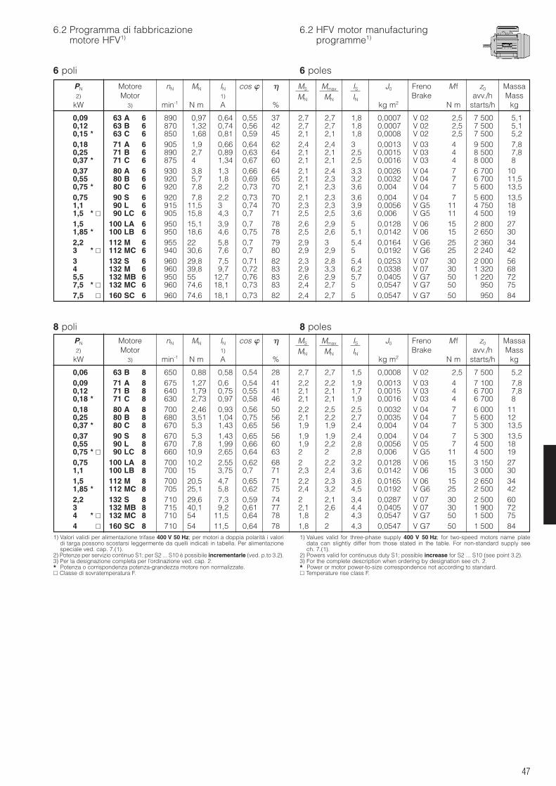
47
6.2 Programma di fabbricazionemotore HFV1)
6.2 HFV motor manufacturingprogramme1)
6 poli 6 poles
8 poli 8 poles
1) Valori validi per alimentazione trifase 400 V 50 Hz; per motori a doppia polarità i valoridi targa possono scostarsi leggermente da quelli indicati in tabella. Per alimentazionespeciale ved. cap. 7.(1).
2) Potenze per servizio continuo S1; per S2 ... S10 è possibile incrementarle (ved. p.to 3.2).3) Per la designazione completa per l’ordinazione ved. cap. 2.* Potenza o corrispondenza potenza-grandezza motore non normalizzate. Classe di sovratemperatura F.
1) Values valid for three-phase supply 400 V 50 Hz; for two-speed motors name platedata can slightly differ from those stated in the table. For non-standard supply seech. 7.(1).
2) Powers valid for continuous duty S1; possible increase for S2 ... S10 (see point 3.2).3) For the complete description when ordering by designation see ch. 2.* Power or motor power-to-size correspondence not according to standard. Temperature rise class F.
PN Motore nN MN IN cos MS Mmax IS J0 Freno M f z0 Massa2) Motor 1) MN MN IN Brake avv./h Mass
kW 3) min-1 N m A % kg m2 N m starts/h kg
PN Motore nN MN IN cos MS Mmax IS J0 Freno M f z0 Massa2) Motor 1) MN MN IN Brake avv./h Mass
kW 3) min-1 N m A % kg m2 N m starts/h kg
0,09 63 A 6 890 0,97 0,64 0,55 37 2,7 2,7 1,8 0,0007 V 02 2,5 7 500 5,10,12 63 B 6 870 1,32 0,74 0,56 42 2,7 2,7 1,8 0,0007 V 02 2,5 7 500 5,10,15 * 63 C 6 850 1,68 0,81 0,59 45 2,1 2,1 1,8 0,0008 V 02 2,5 7 500 5,20,18 71 A 6 905 1,9 0,66 0,64 62 2,4 2,4 3 0,0013 V 03 4 9 500 7,80,25 71 B 6 890 2,7 0,89 0,63 64 2,1 2,1 2,5 0,0015 V 03 4 8 500 7,80,37 * 71 C 6 875 4 1,34 0,67 60 2,1 2,1 2,5 0,0016 V 03 4 8 000 80,37 80 A 6 930 3,8 1,3 0,66 64 2,1 2,4 3,3 0,0026 V 04 7 6 700 100,55 80 B 6 920 5,7 1,8 0,69 65 2,1 2,3 3,2 0,0032 V 04 7 6 700 11,50,75 * 80 C 6 920 7,8 2,2 0,73 70 2,1 2,3 3,6 0,004 V 04 7 5 600 13,50,75 90 S 6 920 7,8 2,2 0,73 70 2,1 2,3 3,6 0,004 V 04 7 5 600 13,51,1 90 L 6 915 11,5 3 0,74 70 2,3 2,3 3,9 0,0056 V G5 11 4 750 181,5 * 90 LC 6 905 15,8 4,3 0,7 71 2,5 2,5 3,6 0,006 V G5 11 4 500 191,5 100 LA 6 950 15,1 3,9 0,7 78 2,6 2,9 5 0,0128 V 06 15 2 800 271,85 * 100 LB 6 950 18,6 4,6 0,75 78 2,5 2,6 5,1 0,0142 V 06 15 2 650 302,2 112 M 6 955 22 5,8 0,7 79 2,9 3 5,4 0,0164 V G6 25 2 360 343 * 112 MC 6 940 30,6 7,6 0,7 80 2,9 2,9 5 0,0192 V G6 25 2 240 423 132 S 6 960 29,8 7,5 0,71 82 2,3 2,8 5,4 0,0253 V 07 30 2 000 564 132 M 6 960 39,8 9,7 0,72 83 2,9 3,3 6,2 0,0338 V 07 30 1 320 685,5 132 MB 6 950 55 12,7 0,76 83 2,6 2,9 5,7 0,0405 V G7 50 1 220 727,5 * 132 MC 6 960 74,6 18,1 0,73 83 2,4 2,7 5 0,0547 V G7 50 950 757,5 160 SC 6 960 74,6 18,1 0,73 82 2,4 2,7 5 0,0547 V G7 50 950 84
0,06 63 B 8 650 0,88 0,58 0,54 28 2,7 2,7 1,5 0,0008 V 02 2,5 7 500 5,20,09 71 A 8 675 1,27 0,6 0,54 41 2,2 2,2 1,9 0,0013 V 03 4 7 100 7,80,12 71 B 8 640 1,79 0,75 0,55 41 2,1 2,1 1,7 0,0015 V 03 4 6 700 7,80,18 * 71 C 8 630 2,73 0,97 0,58 46 2,1 2,1 1,9 0,0016 V 03 4 6 700 80,18 80 A 8 700 2,46 0,93 0,56 50 2,2 2,5 2,5 0,0032 V 04 7 6 000 110,25 80 B 8 680 3,51 1,04 0,75 56 2,1 2,2 2,7 0,0035 V 04 7 5 600 120,37 * 80 C 8 670 5,3 1,43 0,65 56 1,9 1,9 2,4 0,004 V 04 7 5 300 13,50,37 90 S 8 670 5,3 1,43 0,65 56 1,9 1,9 2,4 0,004 V 04 7 5 300 13,50,55 90 L 8 670 7,8 1,99 0,66 60 1,9 2,2 2,8 0,0056 V 05 7 4 500 180,75 * 90 LC 8 660 10,9 2,65 0,64 63 2 2 2,8 0,006 V G5 11 4 500 190,75 100 LA 8 700 10,2 2,55 0,62 68 2 2,2 3,2 0,0128 V 06 15 3 150 271,1 100 LB 8 700 15 3,75 0,7 71 2,3 2,4 3,6 0,0142 V 06 15 3 000 301,5 * 112 M 8 700 20,5 4,7 0,65 71 2,2 2,3 3,6 0,0165 V 06 15 2 650 341,85 * 112 MC 8 705 25,1 5,8 0,62 75 2,4 3,2 4,5 0,0192 V G6 25 2 500 422,2 132 S 8 710 29,6 7,3 0,59 74 2 2,1 3,4 0,0287 V 07 30 2 500 603 132 MB 8 715 40,1 9,2 0,61 77 2,1 2,6 4,4 0,0405 V 07 30 1 900 724 * 132 MC 8 710 54 11,5 0,64 78 1,8 2 4,3 0,0547 V G7 50 1 500 754 160 SC 8 710 54 11,5 0,64 78 1,8 2 4,3 0,0547 V G7 50 1 500 84
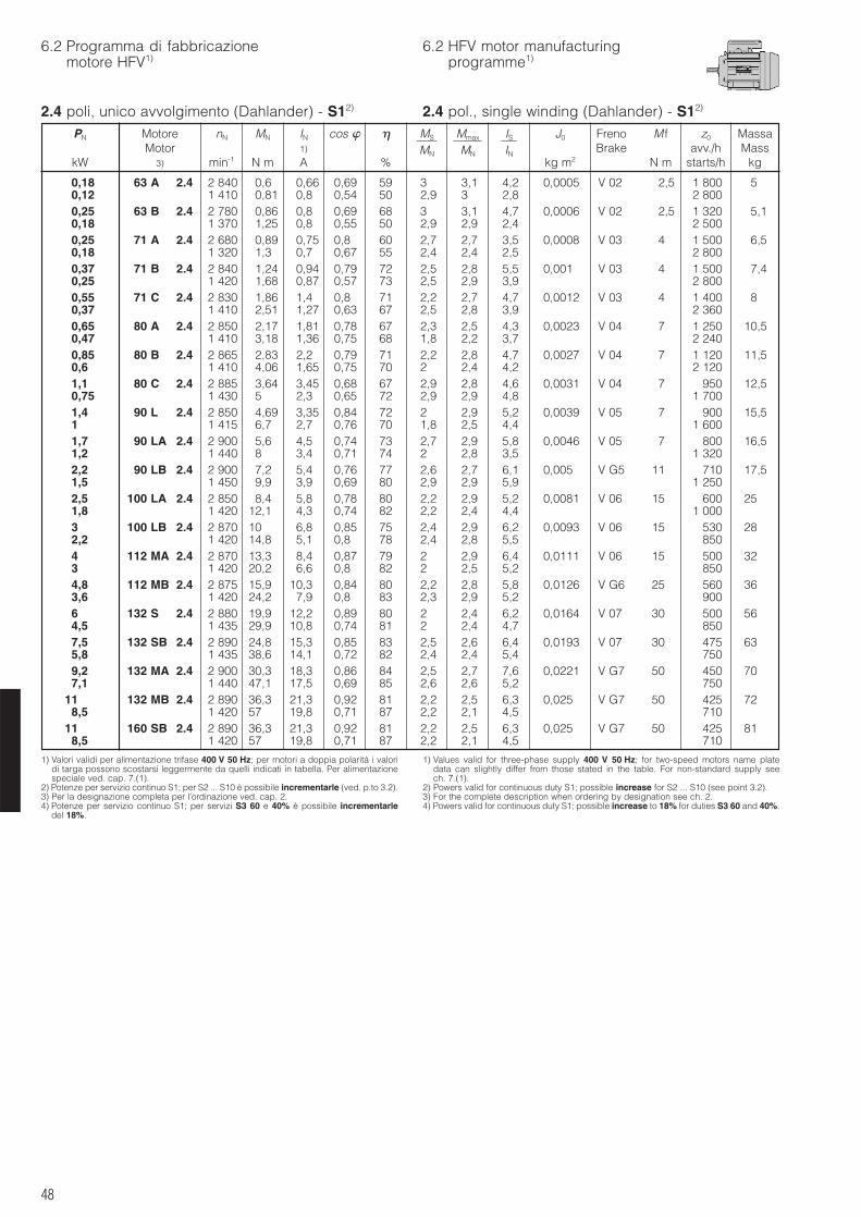
48
6.2 Programma di fabbricazionemotore HFV1)
6.2 HFV motor manufacturingprogramme1)
2.4 poli, unico avvolgimento (Dahlander) - S12)
1) Valori validi per alimentazione trifase 400 V 50 Hz; per motori a doppia polarità i valoridi targa possono scostarsi leggermente da quelli indicati in tabella. Per alimentazionespeciale ved. cap. 7.(1).
2) Potenze per servizio continuo S1; per S2 ... S10 è possibile incrementarle (ved. p.to 3.2).3) Per la designazione completa per l’ordinazione ved. cap. 2.4) Potenze per servizio continuo S1; per servizi S3 60 e 40% è possibile incrementarle
del 18%.
1) Values valid for three-phase supply 400 V 50 Hz; for two-speed motors name platedata can slightly differ from those stated in the table. For non-standard supply seech. 7.(1).
2) Powers valid for continuous duty S1; possible increase for S2 ... S10 (see point 3.2).3) For the complete description when ordering by designation see ch. 2.4) Powers valid for continuous duty S1; possible increase to 18% for duties S3 60 and 40%.
PN Motore nN MN IN cos MS Mmax IS J0 Freno M f z0 MassaMotor 1) MN MN IN Brake avv./h Mass
kW 3) min-1 N m A % kg m2 N m starts/h kg
0,18 63 A 2.4 2 840 0,6 0,66 0,69 59 3 3,1 4,2 0,0005 V 02 2,5 1 800 50,12 1 410 0,81 0,8 0,54 50 2,9 3 2,8 2 8000,25 63 B 2.4 2 780 0,86 0,8 0,69 68 3 3,1 4,7 0,0006 V 02 2,5 1 320 5,10,18 1 370 1,25 0,8 0,55 50 2,9 2,9 2,4 2 5000,25 71 A 2.4 2 680 0,89 0,75 0,8 60 2,7 2,7 3,5 0,0008 V 03 4 1 500 6,50,18 1 320 1,3 0,7 0,67 55 2,4 2,4 2,5 2 8000,37 71 B 2.4 2 840 1,24 0,94 0,79 72 2,5 2,8 5,5 0,001 V 03 4 1 500 7,40,25 1 420 1,68 0,87 0,57 73 2,5 2,9 3,9 2 8000,55 71 C 2.4 2 830 1,86 1,4 0,8 71 2,2 2,7 4,7 0,0012 V 03 4 1 400 80,37 1 410 2,51 1,27 0,63 67 2,5 2,8 3,9 2 3600,65 80 A 2.4 2 850 2,17 1,81 0,78 67 2,3 2,5 4,3 0,0023 V 04 7 1 250 10,50,47 1 410 3,18 1,36 0,75 68 1,8 2,2 3,7 2 2400,85 80 B 2.4 2 865 2,83 2,2 0,79 71 2,2 2,8 4,7 0,0027 V 04 7 1 120 11,50,6 1 410 4,06 1,65 0,75 70 2 2,4 4,2 2 1201,1 80 C 2.4 2 885 3,64 3,45 0,68 67 2,9 2,8 4,6 0,0031 V 04 7 950 12,50,75 1 430 5 2,3 0,65 72 2,9 2,9 4,8 1 7001,4 90 L 2.4 2 850 4,69 3,35 0,84 72 2 2,9 5,2 0,0039 V 05 7 900 15,51 1 415 6,7 2,7 0,76 70 1,8 2,5 4,4 1 6001,7 90 LA 2.4 2 900 5,6 4,5 0,74 73 2,7 2,9 5,8 0,0046 V 05 7 800 16,51,2 1 440 8 3,4 0,71 74 2 2,8 3,5 1 3202,2 90 LB 2.4 2 900 7,2 5,4 0,76 77 2,6 2,7 6,1 0,005 V G5 11 710 17,51,5 1 450 9,9 3,9 0,69 80 2,9 2,9 5,9 1 2502,5 100 LA 2.4 2 850 8,4 5,8 0,78 80 2,2 2,9 5,2 0,0081 V 06 15 600 251,8 1 420 12,1 4,3 0,74 82 2,2 2,4 4,4 1 0003 100 LB 2.4 2 870 10 6,8 0,85 75 2,4 2,9 6,2 0,0093 V 06 15 530 282,2 1 420 14,8 5,1 0,8 78 2,4 2,8 5,5 8504 112 MA 2.4 2 870 13,3 8,4 0,87 79 2 2,9 6,4 0,0111 V 06 15 500 323 1 420 20,2 6,6 0,8 82 2 2,5 5,2 8504,8 112 MB 2.4 2 875 15,9 10,3 0,84 80 2,2 2,8 5,8 0,0126 V G6 25 560 363,6 1 420 24,2 7,9 0,8 83 2,3 2,9 5,2 9006 132 S 2.4 2 880 19,9 12,2 0,89 80 2 2,4 6,2 0,0164 V 07 30 500 564,5 1 435 29,9 10,8 0,74 81 2 2,4 4,7 8507,5 132 SB 2.4 2 890 24,8 15,3 0,85 83 2,5 2,6 6,4 0,0193 V 07 30 475 635,8 1 435 38,6 14,1 0,72 82 2,4 2,4 5,4 7509,2 132 MA 2.4 2 900 30,3 18,3 0,86 84 2,5 2,7 7,6 0,0221 V G7 50 450 707,1 1 440 47,1 17,5 0,69 85 2,6 2,6 5,2 750
11 132 MB 2.4 2 890 36,3 21,3 0,92 81 2,2 2,5 6,3 0,025 V G7 50 425 728,5 1 420 57 19,8 0,71 87 2,2 2,1 4,5 710
11 160 SB 2.4 2 890 36,3 21,3 0,92 81 2,2 2,5 6,3 0,025 V G7 50 425 818,5 1 420 57 19,8 0,71 87 2,2 2,1 4,5 710
2.4 pol., single winding (Dahlander) - S12)
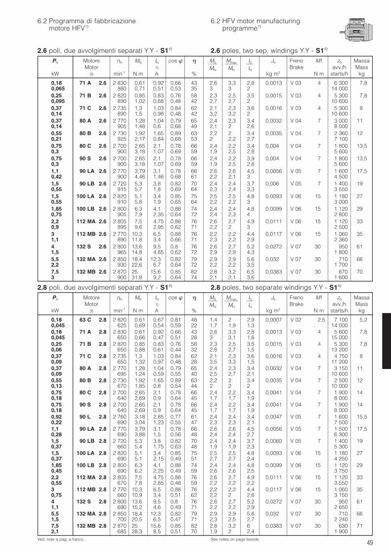
49
6.2 Programma di fabbricazionemotore HFV1)
6.2 HFV motor manufacturingprogramme1)
2.6 poli, due avvolgimenti separati Y.Y - S14)
2.8 poli, due avvolgimenti separati Y.Y - S14) 2.8 poles, two separate windings Y.Y - S14)
Ved. note a pag. a fianco. See notes on page beside.
PN Motore nN MN IN cos MS Mmax IS J0 Freno M f z0 MassaMotor 1) MN MN IN Brake avv./h Mass
kW 3) min-1 N m A % kg m2 N m starts/h kg
PN Motore nN MN IN cos MS Mmax IS J0 Freno M f z0 MassaMotor 1) MN MN IN Brake avv./h Mass
kW 3) min-1 N m A % kg m2 N m starts/h kg
0,18 71 A 2.6 2 830 0,61 0,92 0,66 43 2,6 3,3 2,8 0,0013 V 03 4 6 300 7,80,065 880 0,71 0,51 0,53 35 3 3 2 14 0000,25 71 B 2.6 2 820 0,85 0,83 0,76 58 2,3 2,5 3,5 0,0015 V 03 4 5 300 7,80,095 890 1,02 0,68 0,48 42 2,7 2,7 2 10 6000,37 71 C 2.6 2 735 1,3 1,03 0,84 62 2,1 2,3 3,6 0,0016 V 03 4 5 300 80,14 890 1,5 0,98 0,48 42 3,2 3,2 2 10 6000,37 80 A 2.6 2 770 1,28 1,04 0,79 65 2,4 2,3 3,4 0,0032 V 04 7 3 000 110,14 905 1,48 0,6 0,68 49 2,1 2 2,6 8 0000,55 80 B 2.6 2 730 1,92 1,65 0,89 63 2,2 2 3,4 0,0035 V 04 7 2 360 120,21 925 2,17 0,84 0,68 53 2 2,2 2,7 7 1000,75 80 C 2.6 2 700 2,65 2,1 0,78 66 2,4 2,2 3,4 0,004 V 04 7 1 800 13,50,3 900 3,18 1,07 0,69 59 1,9 2,5 2,8 5 6000,75 90 S 2.6 2 700 2,65 2,1 0,78 66 2,4 2,2 3,9 0,004 V 04 7 1 800 13,50,3 900 3,18 1,07 0,69 59 1,9 2,5 2,8 5 6001,1 90 LA 2.6 2 770 3,79 3,1 0,78 66 2,6 2,6 4,5 0,0056 V 05 7 1 600 17,50,42 900 4,46 1,46 0,68 61 2,2 2,1 3 4 5001,5 90 LB 2.6 2 720 5,3 3,8 0,82 70 2,4 2,4 3,7 0,006 V 05 7 1 400 190,55 915 5,7 1,8 0,69 64 2,3 2,4 3,3 3 5501,5 100 LA 2.6 2 820 5,1 3,4 0,85 75 2,5 2,5 4,8 0,0093 V 06 15 1 180 270,55 910 5,8 1,9 0,65 64 2,2 2,2 3 3 0001,85 100 LB 2.6 2 800 6,3 4,1 0,88 74 2,4 2,4 4,8 0,0099 V 06 15 1 120 290,75 905 7,9 2,35 0,64 72 2,4 2,3 4 2 8002,2 112 MA 2.6 2 805 7,5 4,75 0,88 76 2,6 2,7 4,9 0,0111 V 06 15 1 120 330,9 895 9,6 2,95 0,62 71 2,2 2 3 2 5003 112 MB 2.6 2 770 10,3 6,5 0,88 76 2,2 2,2 4,4 0,0117 V 06 15 1 060 351,1 890 11,8 3,4 0,66 71 2,3 2,2 2,9 2 3604 132 S 2.6 2 800 13,6 9,5 0,8 76 2,6 2,7 5,2 0,0272 V 07 30 950 611,5 965 14,8 4,85 0,62 72 2,9 2,9 4,3 1 8005,5 132 MA 2.6 2 850 18,4 12,3 0,82 79 2,9 2,9 5,6 0,032 V 07 30 710 662,2 930 22,6 6,7 0,64 72 2,2 2,2 3,5 1 7007,5 132 MB 2.6 2 870 25 15,6 0,85 82 2,8 3,2 6,5 0,0383 V 07 30 670 703 900 31,8 9,2 0,64 74 2,1 2,1 3,6 1 600
0,18 63 C 2.8 2 820 0,61 0,67 0,81 48 1,4 2 2,9 0,0007 V 02 2,5 7 100 5,20,045 625 0,69 0,54 0,59 22 1,7 1,9 1,3 14 0000,18 71 A 2.8 2 830 0,61 0,92 0,66 43 2,6 3,3 2,8 0,0013 V 03 4 5 600 7,80,045 650 0,66 0,47 0,51 28 3 3,1 1,6 15 0000,25 71 B 2.8 2 820 0,85 0,83 0,76 58 2,3 2,5 3,5 0,0015 V 03 4 5 300 7,80,06 650 0,88 0,61 0,44 32 2,8 2,7 1,5 13 2000,37 71 C 2.8 2 735 1,3 1,03 0,84 62 2,1 2,3 3,6 0,0016 V 03 4 4 750 80,09 650 1,32 0,97 0,48 28 3,5 3,3 1,5 11 2000,37 80 A 2.8 2 770 1,28 1,04 0,79 65 2,4 2,3 3,4 0,0032 V 04 7 3 150 110,09 695 1,24 0,59 0,55 40 2,5 2,7 2,1 10 6000,55 80 B 2.8 2 730 1,92 1,65 0,89 63 2,2 2 3,4 0,0035 V 04 7 2 500 120,13 670 1,85 0,8 0,54 44 2 2 2 10 0000,75 80 C 2.8 2 700 2,65 2,1 0,78 66 2,4 2,2 3,4 0,0041 V 04 7 1 900 140,18 640 2,69 0,9 0,64 45 1,7 1,7 1,9 8 0000,75 90 S 2.8 2 700 2,65 2,1 0,78 66 2,4 2,2 3,4 0,0041 V 04 7 1 900 140,18 640 2,69 0,9 0,64 45 1,7 1,7 1,9 8 0000,92 90 L 2.8 2 760 3,18 2,85 0,77 61 2,4 2,4 3,4 0,0047 V 05 7 1 600 15,50,22 690 3,04 1,23 0,55 47 2,3 2,3 2,1 7 5001,1 90 LA 2.8 2 770 3,79 3,1 0,78 66 2,6 2,6 4,5 0,0056 V 05 7 1 500 17,50,28 690 3,88 1,5 0,56 48 2,4 2,4 2,7 6 3001,5 90 LB 2.8 2 720 5,3 3,8 0,82 70 2,4 2,4 3,7 0,0060 V 05 7 1 400 190,37 660 5,4 1,75 0,63 48 1,9 1,9 2,3 5 3001,5 100 LA 2.8 2 820 5,1 3,4 0,85 75 2,5 2,5 4,8 0,0093 V 06 15 1 180 270,37 690 5,1 2,15 0,49 51 2,7 2,7 2,4 4 2501,85 100 LB 2.8 2 800 6,3 4,1 0,88 74 2,4 2,4 4,8 0,0099 V 06 15 1 120 290,45 690 6,2 2,25 0,49 59 2,6 2,6 2,5 3 7502,2 112 MA 2.8 2 805 7,5 4,75 0,88 76 2,6 2,7 4,9 0,0111 V 06 15 1 120 330,55 670 7,8 2,85 0,48 59 2,2 2,2 2,2 3 5503 112 MB 2.8 2 770 10,3 6,5 0,88 76 2,2 2,2 4,4 0,0117 V 06 15 1 060 350,75 660 10,9 3,4 0,51 62 2,2 2 2,6 3 1504 132 S 2.8 2 800 13,6 9,5 0,8 76 2,6 2,7 5,2 0,0272 V 07 30 950 611,1 690 15,2 4,6 0,49 71 2,2 2,2 2,9 2 6505,5 132 MA 2.8 2 850 18,4 12,3 0,82 79 2,9 2,9 5,6 0,032 V 07 30 710 661,5 700 20,5 6,5 0,47 71 2,3 2,5 2,7 2 2407,5 132 MB 2.8 2 870 25 15,6 0,85 82 2,8 3,2 6 0,0383 V 07 30 630 712,1 685 28,3 8,5 0,51 70 1,9 2 2,4 1 900
2.6 poles, two sep. windings Y.Y - S14)
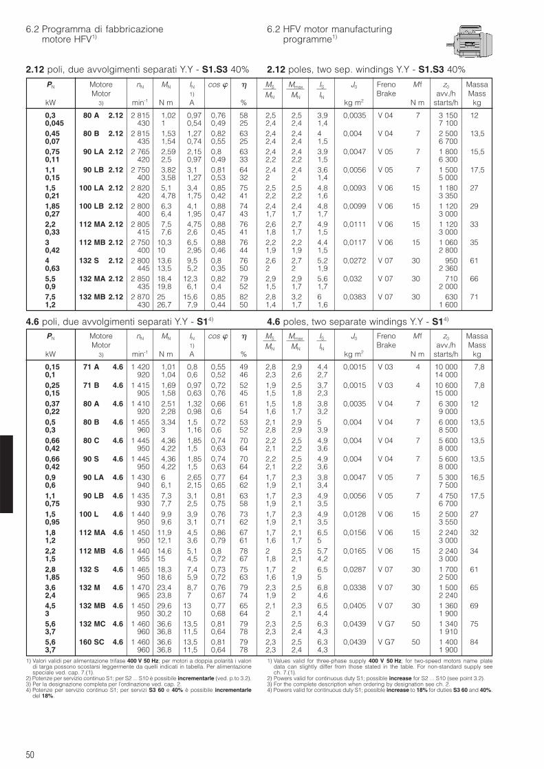
50
6.2 Programma di fabbricazionemotore HFV1)
6.2 HFV motor manufacturingprogramme1)
2.12 poli, due avvolgimenti separati Y.Y - S1.S3 40%
4.6 poli, due avvolgimenti separati Y.Y - S14) 4.6 poles, two separate windings Y.Y - S14)
1) Valori validi per alimentazione trifase 400 V 50 Hz; per motori a doppia polarità i valoridi targa possono scostarsi leggermente da quelli indicati in tabella. Per alimentazionespeciale ved. cap. 7.(1).
2) Potenze per servizio continuo S1; per S2 ... S10 è possibile incrementarle (ved. p.to 3.2).3) Per la designazione completa per l’ordinazione ved. cap. 2.4) Potenze per servizio continuo S1; per servizi S3 60 e 40% è possibile incrementarle
del 18%.
1) Values valid for three-phase supply 400 V 50 Hz; for two-speed motors name platedata can slightly differ from those stated in the table. For non-standard supply seech. 7.(1).
2) Powers valid for continuous duty S1; possible increase for S2 ... S10 (see point 3.2).3) For the complete description when ordering by designation see ch. 2.4) Powers valid for continuous duty S1; possible increase to 18% for duties S3 60 and 40%.
PN Motore nN MN IN cos MS Mmax IS J0 Freno M f z0 MassaMotor 1) MN MN IN Brake avv./h Mass
kW 3) min-1 N m A % kg m2 N m starts/h kg
0,15 71 A 4.6 1 420 1,01 0,8 0,55 49 2,8 2,9 4,4 0,0015 V 03 4 10 000 7,80,1 920 1,04 0,6 0,52 46 2,3 2,6 2,7 14 0000,25 71 B 4.6 1 415 1,69 0,97 0,72 52 1,9 2,5 3,7 0,0015 V 03 4 10 600 7,80,15 905 1,58 0,63 0,76 45 1,5 1,8 2,3 15 0000,37 80 A 4.6 1 410 2,51 1,32 0,66 61 1,5 1,8 3,8 0,0035 V 04 7 6 300 120,22 920 2,28 0,98 0,6 54 1,6 1,7 3,2 9 0000,5 80 B 4.6 1 455 3,34 1,5 0,72 53 2,1 2,9 5 0,004 V 04 7 6 000 13,50,3 960 3 1,16 0,6 52 2,8 2,9 3,9 8 5000,66 80 C 4.6 1 445 4,36 1,85 0,74 70 2,2 2,5 4,9 0,004 V 04 7 5 600 13,50,42 950 4,22 1,5 0,63 64 2,1 2,2 3,6 8 0000,66 90 S 4.6 1 445 4,36 1,85 0,74 70 2,2 2,5 4,9 0,004 V 04 7 5 600 13,50,42 950 4,22 1,5 0,63 64 2,1 2,2 3,6 8 0000,9 90 LA 4.6 1 430 6 2,65 0,77 64 1,7 2,3 3,8 0,0047 V 05 7 5 300 16,50,6 940 6,1 2,15 0,65 62 1,9 2,1 3,4 7 5001,1 90 LB 4.6 1 435 7,3 3,1 0,81 63 1,7 2,3 4,9 0,0056 V 05 7 4 750 17,50,75 930 7,7 2,5 0,75 58 1,9 2,1 3,5 6 7001,5 100 L 4.6 1 440 9,9 3,9 0,76 73 1,7 2,3 4,9 0,0128 V 06 15 2 500 270,95 950 9,6 3,1 0,71 62 1,9 2,1 3,5 3 5501,8 112 MA 4.6 1 450 11,9 4,5 0,86 67 1,7 2,1 6,5 0,0156 V 06 15 2 240 321,2 950 12,1 3,6 0,79 61 1,6 1,7 5 3 0002,2 112 MB 4.6 1 440 14,6 5,1 0,8 78 2 2,5 5,7 0,0165 V 06 15 2 240 341,5 955 15 4,5 0,72 67 1,8 2,1 4,2 3 0002,8 132 S 4.6 1 465 18,3 7,4 0,73 75 1,7 2 6,5 0,0287 V 07 30 1 700 611,85 950 18,6 5,9 0,72 63 1,6 1,9 5 2 5003,6 132 M 4.6 1 470 23,4 8,7 0,76 79 2,3 2,5 6,8 0,0338 V 07 30 1 500 652,4 965 23,8 7 0,67 74 1,9 2 4,6 2 2404,5 132 MB 4.6 1 450 29,6 13 0,77 65 2,1 2,3 6,5 0,0405 V 07 30 1 360 693 950 30,2 10 0,68 64 2 2,1 4,4 1 9005,6 132 MC 4.6 1 460 36,6 13,5 0,81 79 2,3 2,5 6,3 0,0439 V G7 50 1 340 753,7 960 36,8 11,5 0,64 78 2,3 2,4 4,3 1 9105,6 160 SC 4.6 1 460 36,6 13,5 0,81 79 2,3 2,5 6,3 0,0439 V G7 50 1 400 843,7 960 36,8 11,5 0,64 78 2,3 2,4 4,3 1 900
PN Motore nN MN IN cos MS Mmax IS J0 Freno M f z0 MassaMotor 1) MN MN IN Brake avv./h Mass
kW 3) min-1 N m A % kg m2 N m starts/h kg
0,3 80 A 2.12 2 815 1,02 0,97 0,76 58 2,5 2,5 3,9 0,0035 V 04 7 3 150 120,045 430 1 0,54 0,49 25 2,4 2,4 1,4 7 1000,45 80 B 2.12 2 815 1,53 1,27 0,82 63 2,4 2,4 4 0,004 V 04 7 2 500 13,50,07 435 1,54 0,74 0,55 25 2,4 2,4 1,5 6 7000,75 90 LA 2.12 2 765 2,59 2,15 0,8 63 2,4 2,4 3,9 0,0047 V 05 7 1 800 15,50,11 420 2,5 0,97 0,49 33 2,2 2,2 1,5 6 3001,1 90 LB 2.12 2 750 3,82 3,1 0,81 64 2,4 2,4 3,6 0,0056 V 05 7 1 500 17,50,15 400 3,58 1,27 0,53 32 2 2 1,4 5 0001,5 100 LA 2.12 2 820 5,1 3,4 0,85 75 2,5 2,5 4,8 0,0093 V 06 15 1 180 270,21 420 4,78 1,75 0,42 41 2,2 2,2 1,6 3 3501,85 100 LB 2.12 2 800 6,3 4,1 0,88 74 2,4 2,4 4,8 0,0099 V 06 15 1 120 290,27 400 6,4 1,95 0,47 43 1,7 1,7 1,7 3 0002,2 112 MA 2.12 2 805 7,5 4,75 0,88 76 2,6 2,7 4,9 0,0111 V 06 15 1 120 330,33 415 7,6 2,6 0,45 41 1,8 1,7 1,5 3 0003 112 MB 2.12 2 750 10,3 6,5 0,88 76 2,2 2,2 4,4 0,0117 V 06 15 1 060 350,42 400 10 2,95 0,46 44 1,9 1,9 1,5 2 8004 132 S 2.12 2 800 13,6 9,5 0,8 76 2,6 2,7 5,2 0,0272 V 07 30 950 610,63 445 13,5 5,2 0,35 50 2 2 1,9 2 3605,5 132 MA 2.12 2 850 18,4 12,3 0,82 79 2,9 2,9 5,6 0,032 V 07 30 710 660,9 435 19,8 6,1 0,4 52 1,5 1,7 1,7 2 0007,5 132 MB 2.12 2 870 25 15,6 0,85 82 2,8 3,2 6 0,0383 V 07 30 630 711,2 430 26,7 7,9 0,44 50 1,4 1,7 1,6 1 600
2.12 poles, two sep. windings Y.Y - S1.S3 40%
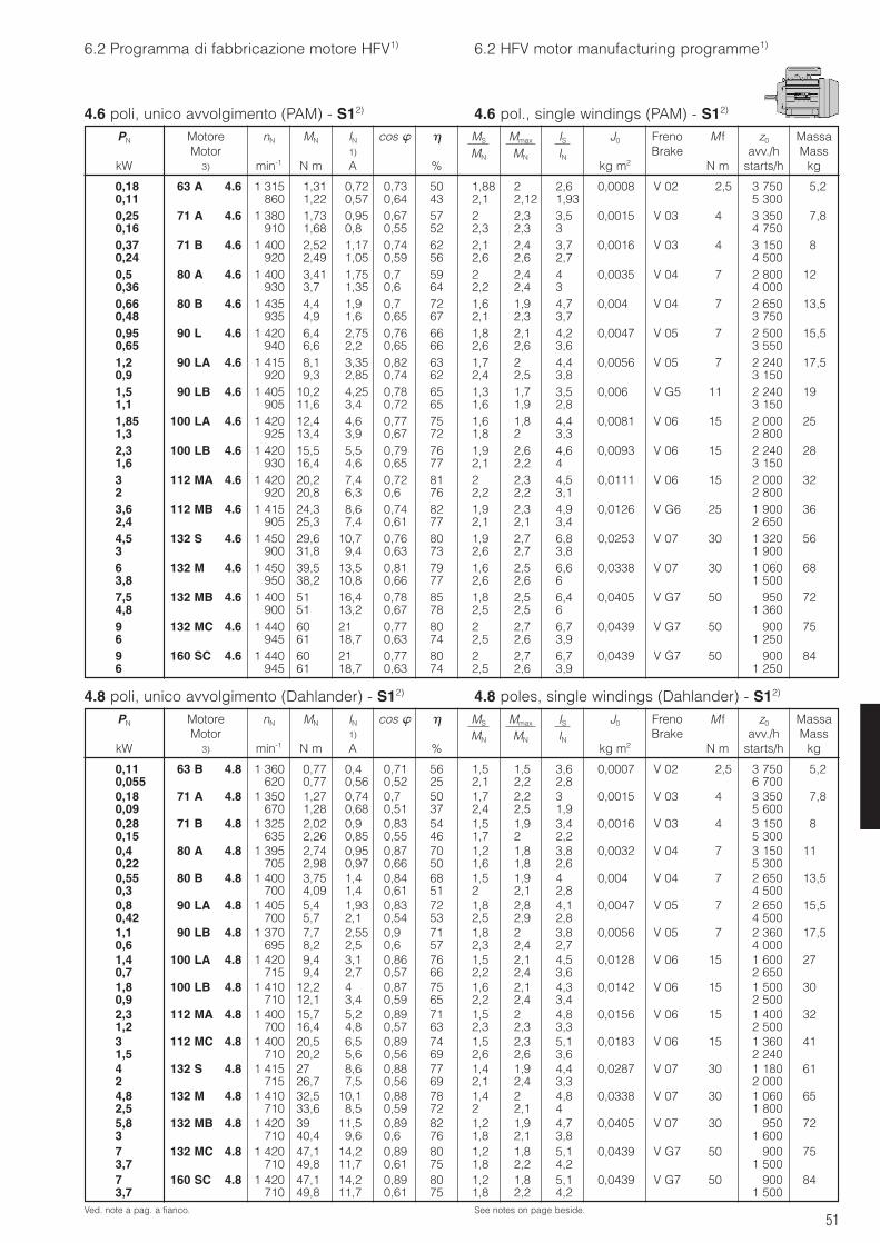
51
6.2 Programma di fabbricazione motore HFV1) 6.2 HFV motor manufacturing programme1)
4.6 poli, unico avvolgimento (PAM) - S12)
4.8 poli, unico avvolgimento (Dahlander) - S12) 4.8 poles, single windings (Dahlander) - S12)
Ved. note a pag. a fianco. See notes on page beside.
PN Motore nN MN IN cos MS Mmax IS J0 Freno M f z0 MassaMotor 1) MN MN IN Brake avv./h Mass
kW 3) min-1 N m A % kg m2 N m starts/h kg
PN Motore nN MN IN cos MS Mmax IS J0 Freno M f z0 MassaMotor 1) MN MN IN Brake avv./h Mass
kW 3) min-1 N m A % kg m2 N m starts/h kg
0,18 63 A 4.6 1 315 1,31 0,72 0,73 50 1,88 2 2,6 0,0008 V 02 2,5 3 750 5,20,11 860 1,22 0,57 0,64 43 2,1 2,12 1,93 5 3000,25 71 A 4.6 1 380 1,73 0,95 0,67 57 2 2,3 3,5 0,0015 V 03 4 3 350 7,80,16 910 1,68 0,8 0,55 52 2,3 2,3 3 4 7500,37 71 B 4.6 1 400 2,52 1,17 0,74 62 2,1 2,4 3,7 0,0016 V 03 4 3 150 80,24 920 2,49 1,05 0,59 56 2,6 2,6 2,7 4 5000,5 80 A 4.6 1 400 3,41 1,75 0,7 59 2 2,4 4 0,0035 V 04 7 2 800 120,36 930 3,7 1,35 0,6 64 2,2 2,4 3 4 0000,66 80 B 4.6 1 435 4,4 1,9 0,7 72 1,6 1,9 4,7 0,004 V 04 7 2 650 13,50,48 935 4,9 1,6 0,65 67 2,1 2,3 3,7 3 7500,95 90 L 4.6 1 420 6,4 2,75 0,76 66 1,8 2,1 4,2 0,0047 V 05 7 2 500 15,50,65 940 6,6 2,2 0,65 66 2,6 2,6 3,6 3 5501,2 90 LA 4.6 1 415 8,1 3,35 0,82 63 1,7 2 4,4 0,0056 V 05 7 2 240 17,50,9 920 9,3 2,85 0,74 62 2,4 2,5 3,8 3 1501,5 90 LB 4.6 1 405 10,2 4,25 0,78 65 1,3 1,7 3,5 0,006 V G5 11 2 240 191,1 905 11,6 3,4 0,72 65 1,6 1,9 2,8 3 1501,85 100 LA 4.6 1 420 12,4 4,6 0,77 75 1,6 1,8 4,4 0,0081 V 06 15 2 000 251,3 925 13,4 3,9 0,67 72 1,8 2 3,3 2 8002,3 100 LB 4.6 1 420 15,5 5,5 0,79 76 1,9 2,6 4,6 0,0093 V 06 15 2 240 281,6 930 16,4 4,6 0,65 77 2,1 2,2 4 3 1503 112 MA 4.6 1 420 20,2 7,4 0,72 81 2 2,3 4,5 0,0111 V 06 15 2 000 322 920 20,8 6,3 0,6 76 2,2 2,2 3,1 2 8003,6 112 MB 4.6 1 415 24,3 8,6 0,74 82 1,9 2,3 4,9 0,0126 V G6 25 1 900 362,4 905 25,3 7,4 0,61 77 2,1 2,1 3,4 2 6504,5 132 S 4.6 1 450 29,6 10,7 0,76 80 1,9 2,7 6,8 0,0253 V 07 30 1 320 563 900 31,8 9,4 0,63 73 2,6 2,7 3,8 1 9006 132 M 4.6 1 450 39,5 13,5 0,81 79 1,6 2,5 6,6 0,0338 V 07 30 1 060 683,8 950 38,2 10,8 0,66 77 2,6 2,6 6 1 5007,5 132 MB 4.6 1 400 51 16,4 0,78 85 1,8 2,5 6,4 0,0405 V G7 50 950 724,8 900 51 13,2 0,67 78 2,5 2,5 6 1 3609 132 MC 4.6 1 440 60 21 0,77 80 2 2,7 6,7 0,0439 V G7 50 900 756 945 61 18,7 0,63 74 2,5 2,6 3,9 1 2509 160 SC 4.6 1 440 60 21 0,77 80 2 2,7 6,7 0,0439 V G7 50 900 846 945 61 18,7 0,63 74 2,5 2,6 3,9 1 250
0,11 63 B 4.8 1 360 0,77 0,4 0,71 56 1,5 1,5 3,6 0,0007 V 02 2,5 3 750 5,20,055 620 0,77 0,56 0,52 25 2,1 2,2 2,8 6 7000,18 71 A 4.8 1 350 1,27 0,74 0,7 50 1,7 2,2 3 0,0015 V 03 4 3 350 7,80,09 670 1,28 0,68 0,51 37 2,4 2,5 1,9 5 6000,28 71 B 4.8 1 325 2,02 0,9 0,83 54 1,5 1,9 3,4 0,0016 V 03 4 3 150 80,15 635 2,26 0,85 0,55 46 1,7 2 2,2 5 3000,4 80 A 4.8 1 395 2,74 0,95 0,87 70 1,2 1,8 3,8 0,0032 V 04 7 3 150 110,22 705 2,98 0,97 0,66 50 1,6 1,8 2,6 5 3000,55 80 B 4.8 1 400 3,75 1,4 0,84 68 1,5 1,9 4 0,004 V 04 7 2 650 13,50,3 700 4,09 1,4 0,61 51 2 2,1 2,8 4 5000,8 90 LA 4.8 1 405 5,4 1,93 0,83 72 1,8 2,8 4,1 0,0047 V 05 7 2 650 15,50,42 700 5,7 2,1 0,54 53 2,5 2,9 2,8 4 5001,1 90 LB 4.8 1 370 7,7 2,55 0,9 71 1,8 2 3,8 0,0056 V 05 7 2 360 17,50,6 695 8,2 2,5 0,6 57 2,3 2,4 2,7 4 0001,4 100 LA 4.8 1 420 9,4 3,1 0,86 76 1,5 2,1 4,5 0,0128 V 06 15 1 600 270,7 715 9,4 2,7 0,57 66 2,2 2,4 3,6 2 6501,8 100 LB 4.8 1 410 12,2 4 0,87 75 1,6 2,1 4,3 0,0142 V 06 15 1 500 300,9 710 12,1 3,4 0,59 65 2,2 2,4 3,4 2 5002,3 112 MA 4.8 1 400 15,7 5,2 0,89 71 1,5 2 4,8 0,0156 V 06 15 1 400 321,2 700 16,4 4,8 0,57 63 2,3 2,3 3,3 2 5003 112 MC 4.8 1 400 20,5 6,5 0,89 74 1,5 2,3 5,1 0,0183 V 06 15 1 360 411,5 710 20,2 5,6 0,56 69 2,6 2,6 3,6 2 2404 132 S 4.8 1 415 27 8,6 0,88 77 1,4 1,9 4,4 0,0287 V 07 30 1 180 612 715 26,7 7,5 0,56 69 2,1 2,4 3,3 2 0004,8 132 M 4.8 1 410 32,5 10,1 0,88 78 1,4 2 4,8 0,0338 V 07 30 1 060 652,5 710 33,6 8,5 0,59 72 2 2,1 4 1 8005,8 132 MB 4.8 1 420 39 11,5 0,89 82 1,2 1,9 4,7 0,0405 V 07 30 950 723 710 40,4 9,6 0,6 76 1,8 2,1 3,8 1 6007 132 MC 4.8 1 420 47,1 14,2 0,89 80 1,2 1,8 5,1 0,0439 V G7 50 900 753,7 710 49,8 11,7 0,61 75 1,8 2,2 4,2 1 5007 160 SC 4.8 1 420 47,1 14,2 0,89 80 1,2 1,8 5,1 0,0439 V G7 50 900 843,7 710 49,8 11,7 0,61 75 1,8 2,2 4,2 1 500
4.6 pol., single windings (PAM) - S12)
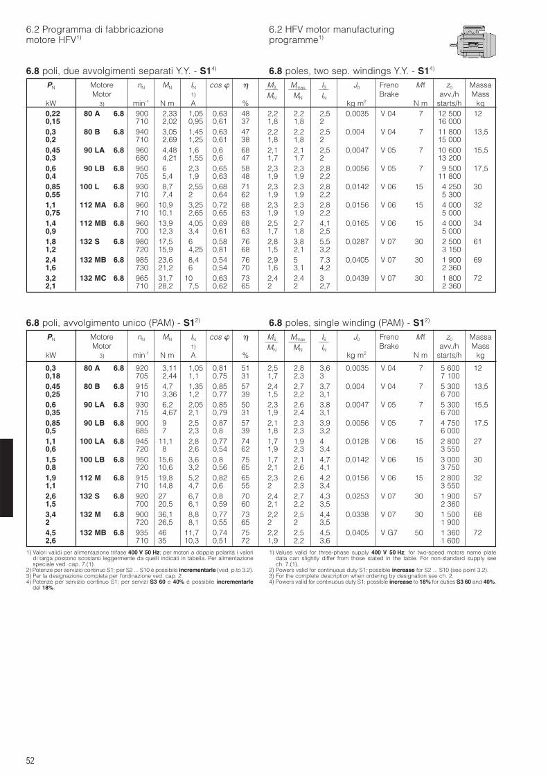
52
6.2 Programma di fabbricazionemotore HFV1)
6.2 HFV motor manufacturingprogramme1)
6.8 poli, due avvolgimenti separati Y.Y. - S14)
6.8 poli, avvolgimento unico (PAM) - S12) 6.8 poles, single winding (PAM) - S12)
1) Valori validi per alimentazione trifase 400 V 50 Hz; per motori a doppia polarità i valoridi targa possono scostarsi leggermente da quelli indicati in tabella. Per alimentazionespeciale ved. cap. 7.(1).
2) Potenze per servizio continuo S1; per S2 ... S10 è possibile incrementarle (ved. p.to 3.2).3) Per la designazione completa per l’ordinazione ved. cap. 2.4) Potenze per servizio continuo S1; per servizi S3 60 e 40% è possibile incrementarle
del 18%.
1) Values valid for three-phase supply 400 V 50 Hz; for two-speed motors name platedata can slightly differ from those stated in the table. For non-standard supply seech. 7.(1).
2) Powers valid for continuous duty S1; possible increase for S2 ... S10 (see point 3.2).3) For the complete description when ordering by designation see ch. 2.4) Powers valid for continuous duty S1; possible increase to 18% for duties S3 60 and 40%.
PN Motore nN MN IN cos MS Mmax IS J0 Freno M f z0 MassaMotor 1) MN MN IN Brake avv./h Mass
kW 3) min-1 N m A % kg m2 N m starts/h kg0,22 80 A 6.8 900 2,33 1,05 0,63 48 2,2 2,2 2,5 0,0035 V 04 7 12 500 120,15 710 2,02 0,95 0,61 37 1,8 1,8 2 16 0000,3 80 B 6.8 940 3,05 1,45 0,63 47 2,2 2,2 2,5 0,004 V 04 7 11 800 13,50,2 710 2,69 1,25 0,61 38 1,8 1,8 2 15 0000,45 90 LA 6.8 960 4,48 1,6 0,6 68 2,1 2,1 2,5 0,0047 V 05 7 10 600 15,50,3 680 4,21 1,55 0,6 47 1,7 1,7 2 13 2000,6 90 LB 6.8 950 6 2,3 0,65 58 2,3 2,3 2,8 0,0056 V 05 7 9 500 17,50,4 705 5,4 1,9 0,63 48 1,9 1,9 2,2 11 8000,85 100 L 6.8 930 8,7 2,55 0,68 71 2,3 2,3 2,8 0,0142 V 06 15 4 250 300,55 710 7,4 2 0,64 62 1,9 1,9 2,2 5 3001,1 112 MA 6.8 960 10,9 3,25 0,72 68 2,3 2,3 2,8 0,0156 V 06 15 4 000 320,75 710 10,1 2,65 0,65 63 1,9 1,9 2,2 5 0001,4 112 MB 6.8 960 13,9 4,05 0,69 68 2,5 2,7 4,1 0,0165 V 06 15 4 000 340,9 700 12,3 3,4 0,61 63 1,7 1,8 2,5 5 0001,8 132 S 6.8 980 17,5 6 0,58 76 2,8 3,8 5,5 0,0287 V 07 30 2 500 611,2 720 15,9 4,25 0,81 68 1,5 2,1 3,2 3 1502,4 132 MB 6.8 985 23,6 8,4 0,54 76 2,9 5 7,3 0,0405 V 07 30 1 900 691,6 730 21,2 6 0,54 70 1,6 3,1 4,2 2 3603,2 132 MC 6.8 965 31,7 10 0,63 73 2,4 2,4 3 0,0439 V 07 30 1 800 722,1 710 28,2 7,5 0,62 65 2 2 2,7 2 360
PN Motore nN MN IN cos MS Mmax IS J0 Freno M f z0 MassaMotor 1) MN MN IN Brake avv./h Mass
kW 3) min-1 N m A % kg m2 N m starts/h kg
0,3 80 A 6.8 920 3,11 1,05 0,81 51 2,5 2,8 3,6 0,0035 V 04 7 5 600 120,18 705 2,44 1,1 0,75 31 1,7 2,3 3 7 1000,45 80 B 6.8 915 4,7 1,35 0,85 57 2,4 2,7 3,7 0,004 V 04 7 5 300 13,50,25 710 3,36 1,2 0,77 39 1,5 2,2 3,1 6 7000,6 90 LA 6.8 930 6,2 2,05 0,85 50 2,3 2,6 3,8 0,0047 V 05 7 5 300 15,50,35 715 4,67 2,1 0,79 31 1,9 2,4 3,1 6 7000,85 90 LB 6.8 900 9 2,5 0,87 57 2,1 2,3 3,9 0,0056 V 05 7 4 750 17,50,5 685 7 2,3 0,8 39 1,8 2,3 3,2 6 0001,1 100 LA 6.8 945 11,1 2,8 0,77 74 1,7 1,9 4 0,0128 V 06 15 2 800 270,6 720 8 2,6 0,54 62 1,9 2,3 3,4 3 5501,5 100 LB 6.8 950 15,6 3,6 0,8 75 1,7 2,1 4,7 0,0142 V 06 15 3 000 300,8 720 10,6 3,2 0,56 65 2,1 2,6 4,1 3 7501,9 112 M 6.8 915 19,8 5,2 0,82 65 2,3 2,6 4,2 0,0156 V 06 15 2 800 321,1 710 14,8 4,7 0,6 55 2 2,3 3,4 3 5502,6 132 S 6.8 920 27 6,7 0,8 70 2,4 2,7 4,3 0,0253 V 07 30 1 900 571,5 700 20,5 6,1 0,59 60 2,1 2,2 3,5 2 3603,4 132 M 6.8 900 36,1 8,8 0,77 73 2,2 2,5 4,4 0,0338 V 07 30 1 500 682 720 26,5 8,1 0,55 65 2 2 3,5 1 9004,5 132 MB 6.8 935 46 11,7 0,74 75 2,2 2,5 4,5 0,0405 V G7 50 1 360 722,6 710 35 10,3 0,51 72 1,9 2,2 3,6 1 600
6.8 poles, two sep. windings Y.Y. - S14)
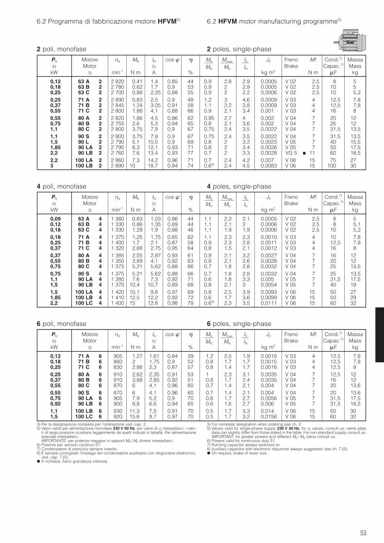
53
6.2 Programma di fabbricazione motore HFVM5) 6.2 HFVM motor manufacturing programme5)
2 poli, monofase
4 poli, monofase 4 poles, single-phase
6 poli, monofase 6 poles, single-phase
3) Per la designazione completa per l’ordinazione ved. cap. 2.5) Valori validi per alimentazione monofase 230 V 50 Hz; per valori di z0 interpellarci; i valo-
ri di targa possono scostarsi leggermente da quelli indicati in tabella. Per alimentazionespeciale interpellarci.IMPORTANTE: per potenze maggiori e rapporti MS / MN diversi interpellarci.
6) Potenze per servizio continuo S1.7) Condensatore di esercizio sempre inserito.8) È sempre consigliato l’impiego del condensatore ausilisario con disgiuntore elettronico,
ved. cap. 7.(5). A richiesta, freno grandezza inferiore.
3) For complete designation when ordering see ch. 2.5) Values valid for single-phase supply 230 V 50 Hz; for z0 values, consult us; name plate
data can slightly differ from those stated in the table. For non-standard supply consult us.IMPORTANT: for greater powers and different MS / MN ratios consult us.
6) Powers valid for continuous duty S1.7) Running capacitor always switched on.8) Auxiliary capacitor with electronic disjunctor always suggested; see ch. 7.(5). On request, brake of lower size.
PN Motore nN MN IN cos MS Mmax IS J0 Freno M f Cond.7) Massa6) Motor 5) MN MN IN Brake Capac.7) Mass
kW 3) min-1 N m A % kg m2 N m F kg
0,12 63 A 2 2 820 0,41 1,4 0,85 44 0,9 2,8 2,9 0,0005 V 02 2,5 8 50,18 63 B 2 2 780 0,62 1,7 0,9 53 0,9 2 2,9 0,0005 V 02 2,5 10 50,25 63 C 2 2 700 0,88 2,25 0,88 55 0,9 2 2,2 0,0006 V 02 2,5 10 5,20,25 71 A 2 2 890 0,83 2,5 0,9 48 1,2 3 4,6 0,0009 V 03 4 12,5 7,80,37 71 B 2 2 845 1,24 3,05 0,91 58 1,1 2,2 3,8 0,0009 V 03 4 12,5 7,80,55 71 C 2 2 800 1,88 4,1 0,88 66 0,9 2,1 3,4 0,001 V 03 4 16 80,55 80 A 2 2 820 1,86 4,5 0,86 62 0,95 2,7 4 0,002 V 04 7 20 120,75 80 B 2 2 755 2,6 5,3 0,94 65 0,8 2,1 3,6 0,002 V 04 7 25 121,1 80 C 2 2 800 3,75 7,9 0,9 67 0,75 2,4 3,5 0,0022 V 04 7 31,5 13,51,1 90 S 2 2 800 3,75 7,9 0,9 67 0,75 2,4 3,5 0,0022 V 04 7 31,5 13,51,5 90 L 2 2 790 5,1 10,5 0,9 69 0,8 2 3,2 0,0023 V 05 7 40 15,51,85 90 LA 2 2 790 6,3 12,1 0,93 71 0,8 2 3,4 0,0026 V 05 7 50 17,52,2 90 LB 2 2 760 7,6 13,4 0,93 77 0,7 2 3,3 0,0028 VG 5 11 60 18,52,2 100 LA 2 2 860 7,3 14,2 0,96 71 0,7 2,4 4,2 0,007 V 06 15 75 273 100 LB 2 2 890 10 18,7 0,94 74 0,68) 2,4 4,5 0,0083 V 06 15 100 30
PN Motore nN MN IN cos MS Mmax IS J0 Freno M f Cond.7) Massa6) Motor 5) MN MN IN Brake Capac.7) Mass
kW 3) min-1 N m A % kg m2 N m F kg
0,09 63 A 4 1 360 0,63 1,03 0,86 44 1,1 2,2 2,1 0,0005 V 02 2,5 8 50,12 63 B 4 1 330 0,86 1,35 0,89 44 1,1 2,1 2 0,0006 V 02 2,5 8 5,10,18 63 C 4 1 330 1,29 1,9 0,88 46 1,1 1,9 1,9 0,0006 V 02 2,5 10 5,20,18 71 A 4 1 370 1,25 1,75 0,85 62 1,1 2,3 2,3 0,0010 V 03 4 10 7,80,25 71 B 4 1 400 1,7 2,1 0,87 58 0,9 2,3 2,8 0,0011 V 03 4 12,5 7,80,37 71 C 4 1 320 2,68 2,75 0,95 64 0,8 1,5 2,1 0,0012 V 03 4 16 80,37 80 A 4 1 385 2,55 2,87 0,93 61 0,9 2,1 3,2 0,0027 V 04 7 16 120,55 80 B 4 1 350 3,89 4,1 0,92 63 0,8 2,1 2,6 0,0028 V 04 7 20 120,75 80 C 4 1 375 5,21 5,62 0,88 66 0,7 1,8 2,8 0,0032 V 04 7 25 13,50,75 90 S 4 1 375 5,21 5,62 0,88 66 0,7 1,8 2,8 0,0032 V 04 7 25 13,51,1 90 LA 4 1 380 7,6 7,3 0,92 71 0,6 1,8 3,3 0,005 V 05 7 31,5 17,51,5 * 90 LB 4 1 370 10,4 10,7 0,89 68 0,8 2,1 3 0,0054 V 05 7 40 191,5 100 LA 4 1 420 10,1 9,8 0,97 69 0,8 2,5 3,9 0,0093 V 06 15 50 271,85 100 LB 4 1 410 12,5 12,2 0,92 72 0,6 1,7 3,6 0,0099 V 06 15 50 292,2 100 LC 4 1 400 15 12,8 0,98 78 0,68) 2,3 3,5 0,0111 V 06 15 60 32
PN Motore nN MN IN cos MS Mmax IS J0 Freno M f Cond.7) Massa6) Motor 5) MN MN IN Brake Capac.7) Mass
kW 3) min-1 N m A % kg m2 N m F kg
0,12 71 A 6 905 1,27 1,61 0,84 39 1,2 2,5 1,9 0,0015 V 03 4 12,5 7,80,18 71 B 6 860 2 1,75 0,9 52 0,8 1,7 1,7 0,0015 V 03 4 12,5 7,80,25 71 C 6 830 2,88 2,3 0,87 57 0,8 1,4 1,7 0,0016 V 03 4 12,5 80,25 80 A 6 910 2,62 2,35 0,91 53 1 2,3 3,1 0,0035 V 04 7 12,5 120,37 80 B 6 910 3,88 2,85 0,92 51 0,8 1,7 2,4 0,0035 V 04 7 16 120,55 80 C 6 870 6 4,1 0,96 60 0,7 1,4 2,1 0,004 V 04 7 20 13,60,55 90 S 6 870 6 4,1 0,96 60 0,7 1,4 2,1 0,004 V 04 7 20 13,60,75 90 LA 6 905 7,9 5,2 0,9 70 0,6 1,7 2,7 0,0056 V 05 7 31,5 17,50,92 90 LB 6 900 9,8 6,6 0,94 65 0,6 1,6 2,7 0,006 V 05 7 31,5 18,51,1 100 LB 6 930 11,3 7,5 0,91 70 0,5 1,7 3,3 0,014 V 06 15 50 301,5 100 LC 6 920 15,6 9,7 0,97 70 0,5 1,7 3,2 0,0156 V 06 15 60 32
2 poles, single-phase
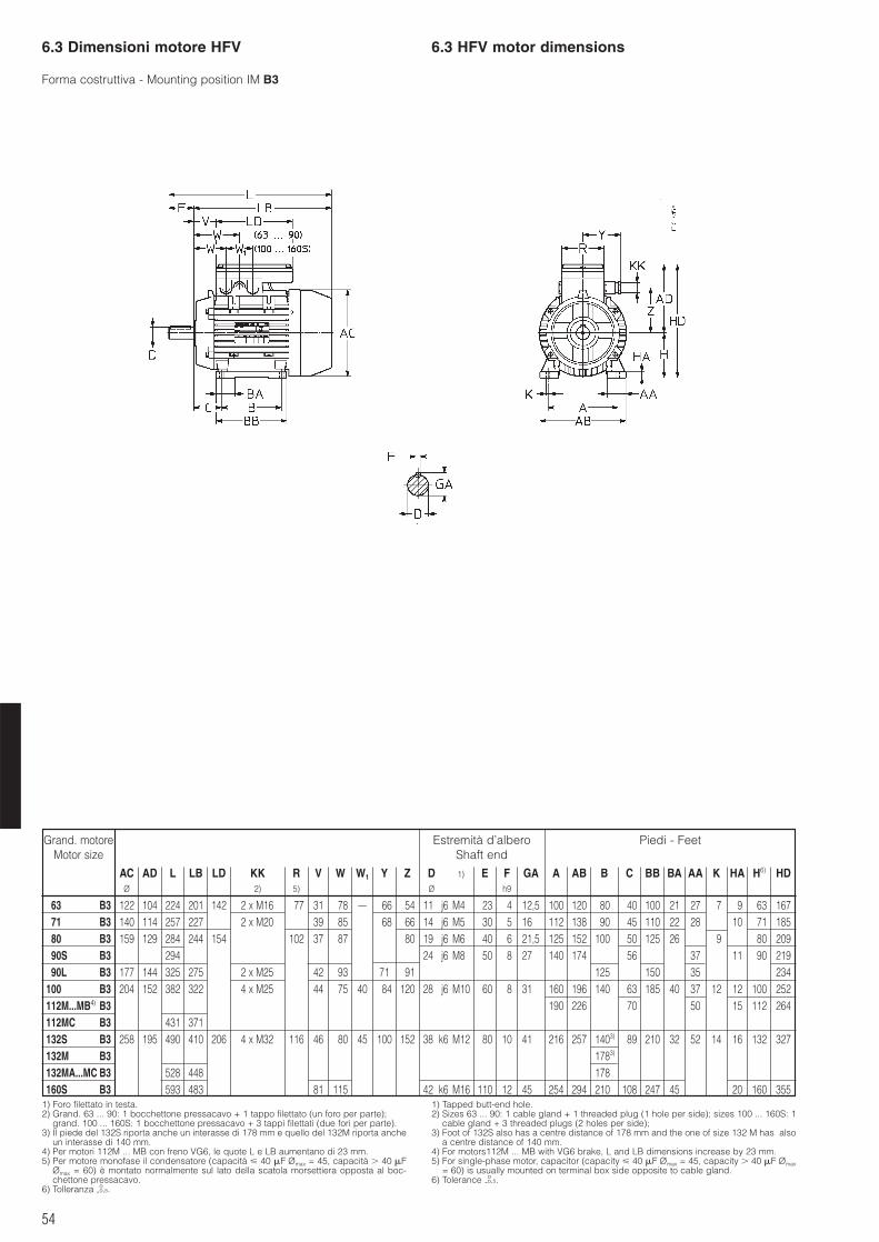
54
6.3 Dimensioni motore HFV 6.3 HFV motor dimensions
1) Foro filettato in testa.2) Grand. 63 ... 90: 1 bocchettone pressacavo + 1 tappo filettato (un foro per parte);
grand. 100 ... 160S: 1 bocchettone pressacavo + 3 tappi filettati (due fori per parte).3) Il piede del 132S riporta anche un interasse di 178 mm e quello del 132M riporta anche
un interasse di 140 mm.4) Per motori 112M ... MB con freno VG6, le quote L e LB aumentano di 23 mm.5) Per motore monofase il condensatore (capacità 40 F Ømax = 45, capacità 40 F
Ømax = 60) è montato normalmente sul lato della scatola morsettiera opposta al boc-chettone pressacavo.
6) Tolleranza -oo,5.
1) Tapped butt-end hole.2) Sizes 63 ... 90: 1 cable gland + 1 threaded plug (1 hole per side); sizes 100 ... 160S: 1
cable gland + 3 threaded plugs (2 holes per side);3) Foot of 132S also has a centre distance of 178 mm and the one of size 132 M has also
a centre distance of 140 mm.4) For motors112M ... MB with VG6 brake, L and LB dimensions increase by 23 mm.5) For single-phase motor, capacitor (capacity 40 F Ømax = 45, capacity 40 F Ømax
= 60) is usually mounted on terminal box side opposite to cable gland.6) Tolerance -o
o,5.
Forma costruttiva - Mounting position IM B3
Grand. motoreMotor size
AC AD L LB LD KK R V W W1 Y Z D 1) E F GA A AB B C BB BA AA K HA H6) HDØ 2) 5) Ø h9
63 B3 122 104 224 201 142 2 x M16 77 31 78 – 66 54 11 j6 M4 23 4 12,5 100 120 80 40 100 21 27 7 9 63 16771 B3 140 114 257 227 2 x M20 39 85 68 66 14 j6 M5 30 5 16 112 138 90 45 110 22 28 10 71 18580 B3 159 129 284 244 154 102 37 87 80 19 j6 M6 40 6 21,5 125 152 100 50 125 26 9 80 20990S B3 294 24 j6 M8 50 8 27 140 174 56 37 11 90 21990L B3 177 144 325 275 2 x M25 42 93 71 91 125 150 35 234
100 B3 204 152 382 322 4 x M25 44 75 40 84 120 28 j6 M10 60 8 31 160 196 1403) 63 185 40 37 12 12 100 252112M...MB4) B3 190 226 70 50 15 112 264112MC B3 431 371132S B3 258 195 490 410 206 4 x M32 116 46 80 45 100 152 38 k6 M12 80 10 41 216 257 1403) 89 210 32 52 14 16 132 327132M B3 1783)
132MA...MC B3 528 448 178160S B3 593 483 81 115 42 k6 M16 110 12 45 254 294 210 108 247 45 20 160 355
Estremità d’alberoShaft end
Piedi - Feet
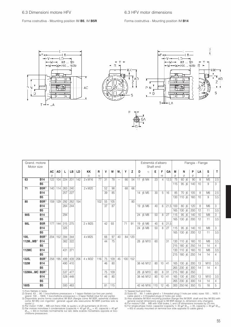
55
6.3 Dimensioni motore HFV 6.3 HFV motor dimensions
Forma costruttiva - Mounting position IM B5, IM B5R Forma costruttiva - Mounting position IM B14
1) Foro filettato in testa.2) Grand. 63 ... 90: 1 bocchettone pressacavo + 1 tappo filettato (un foro per parte);
grand. 100 ... 160S: 1 bocchettone pressacavo + 3 tappi filettati (due fori per parte).3) Disponibile anche forma costruttiva IM B5A (flangia come IM B5R, estremità d’albero
come IM B5) con ingombri generali uguali alla esecuzione IM B5R (cambia solo laquota L).
4) Per motori 112M ... MB con freno VG6, le quote L e LB aumentano di 23 mm.5) Per motore monofase il condensatore (capacità 40 F Ømax = 45, capacità > 40 F
Ømax = 60) è montato normalmente sul lato della scatola morsettiera opposta al boc-chettone pressacavo.
1) Tapped butt-end hole.2) Sizes 63 ... 90: 1 cable gland + 1 threaded plug (1 hole per side); sizes 100 ... 160S: 1
cable gland + 3 threaded plugs (2 holes per side).3) Also available IM B5A mounting position (flange like IM B5R, shaft end like IM B5) with
general overall dimensions equal to IM B5R design (L dimension only changes).4) For motors112M ... MB with VG6 brake, L and LB dimensions increase by 23 mm.5) For single-phase motor, capacitor (capacity 40 F Ømax = 45, capacity > 40 F Ømax
= 60) is usually mounted on terminal box side opposite to cable gland.
Grand. motoreMotor size
AC AD L LB LD KK R1 V W W1 Y Z D 1) E F GA M N P LA S TØ 2) 5) Ø h9 Ø Ø Ø Ø
63 B14 122 104 224 201 142 2 x M16 77 31 78 – 66 54 11 j6 M4 23 4 12,5 75 60 j6 90 8 M5 2,5B5 115 95 j6 140 10 9 3
71 B5R3) 140 114 263 240 2 x M20 52 98 68 66B14 257 227 39 85 14 j6 M5 30 5 16 85 70 j6 105 8 M6 2,5B5 130 110 j6 160 10 9 3,5
80 B5R3) 159 129 292 262 154 102 55 105 80B14 284 244 37 87 19 j6 M6 40 6 21,5 100 80 j6 120 8 M6 3B5 165 130 j6 200 12 11 3,5
90S B14 294 24 j6 M8 50 8 27 115 95 j6 140 10 M8 3B5 165 130 j6 200 12 11 3,5
90L B5R 177 144 315 275 2 x M25 42 93 71 91 19 j6 M6 40 6 21,5B14 325 24 j6 M8 50 8 27 115 95 j6 140 10 M8 3B5 165 130 j6 200 12 11 3,5
100, B5R3) 204 152 394 344 4 x M25 66 97 40 84 120112M...MB4) B14 382 322 44 75 28 j6 M10 60 31 130 110 j6 160 10 M8 3,5
B5 215 180 j6 250 14 14 4112MC B14 431 371 130 110 j6 160 10 M8 3,5
B5 215 180 j6 250 14 14 4132S, B5R3) 258 195 499 439 206 4 x M32 116 75 109 45 100 152132M B14 490 410 46 80 38 k6 M12 80 10 41 165 130 j6 200 13 M10 3,5
B5 265 230 j6 300 14 14 4132MA...MC B5R3) 537 477 75 109 28 j6 M10 60 8 31 215 180 j6 250
B14 528 448 46 80 38 k6 M12 80 10 41 165 130 j6 200 13 M10 3,5B5 265 230 j6 300 14 14 4
160S B5 593 483 81 115 42 k6 M16 110 12 45 300 250 h6 350 15 18 5
Estremità d’alberoShaft end
Flangia - Flange
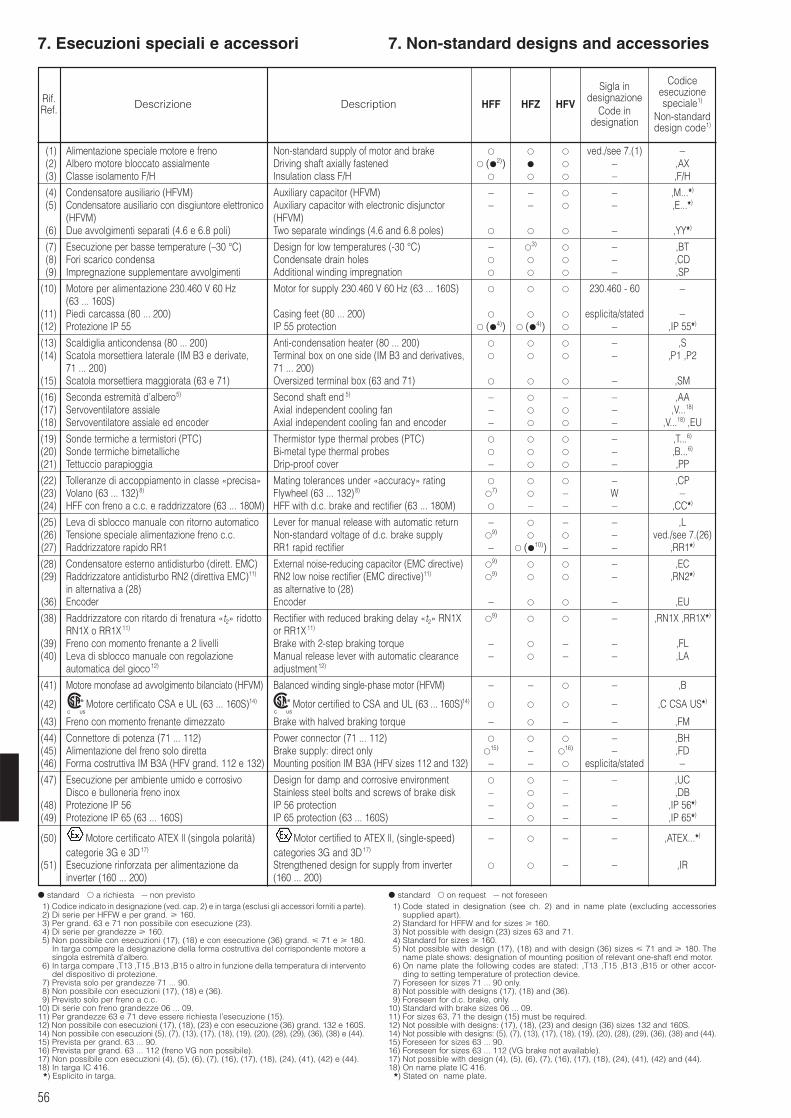
56
7. Esecuzioni speciali e accessori 7. Non-standard designs and accessories
Rif.Ref. Descrizione Description
Sigla indesignazione
Code indesignation
Codiceesecuzionespeciale1)
Non-standarddesign code1)
(1) Alimentazione speciale motore e freno Non-standard supply of motor and brake ved./see 7.(1) –(2) Albero motore bloccato assialmente Driving shaft axially fastened (
2)) – ,AX(3) Classe isolamento F/H Insulation class F/H – ,F/H
(4) Condensatore ausiliario (HFVM) Auxiliary capacitor (HFVM) – – – ,M...*)
(5) Condensatore ausiliario con disgiuntore elettronico Auxiliary capacitor with electronic disjunctor – – – ,E...*)
(HFVM) (HFVM)(6) Due avvolgimenti separati (4.6 e 6.8 poli) Two separate windings (4.6 and 6.8 poles) – ,YY*)
(7) Esecuzione per basse temperature (–30 °C) Design for low temperatures (-30 °C) – 3)
– ,BT(8) Fori scarico condensa Condensate drain holes – ,CD(9) Impregnazione supplementare avvolgimenti Additional winding impregnation – ,SP
(10) Motore per alimentazione 230.460 V 60 Hz Motor for supply 230.460 V 60 Hz (63 ... 160S) 230.460 - 60 –(63 ... 160S)
(11) Piedi carcassa (80 ... 200) Casing feet (80 ... 200) esplicita/stated –(12) Protezione IP 55 IP 55 protection (
4)) (4)) – ,IP 55*)
(13) Scaldiglia anticondensa (80 ... 200) Anti-condensation heater (80 ... 200) – ,S(14) Scatola morsettiera laterale (IM B3 e derivate, Terminal box on one side (IM B3 and derivatives, – ,P1 ,P2
71 ... 200) 71 ... 200)(15) Scatola morsettiera maggiorata (63 e 71) Oversized terminal box (63 and 71) – ,SM
(16) Seconda estremità d’albero5) Second shaft end 5) – – – ,AA(17) Servoventilatore assiale Axial independent cooling fan – – ,V...18)
(18) Servoventilatore assiale ed encoder Axial independent cooling fan and encoder – – ,V...18) ,EU
(19) Sonde termiche a termistori (PTC) Thermistor type thermal probes (PTC) – ,T...6)
(20) Sonde termiche bimetalliche Bi-metal type thermal probes – ,B...6)
(21) Tettuccio parapioggia Drip-proof cover – – ,PP
(22) Tolleranze di accoppiamento in classe «precisa» Mating tolerances under «accuracy» rating – ,CP(23) Volano (63 ... 132)8) Flywheel (63 ... 132)8)
7)
– W –(24) HFF con freno a c.c. e raddrizzatore (63 ... 180M) HFF with d.c. brake and rectifier (63 ... 180M) – – – ,CC*)
(25) Leva di sblocco manuale con ritorno automatico Lever for manual release with automatic return – – – ,L(26) Tensione speciale alimentazione freno c.c. Non-standard voltage of d.c. brake supply
9) – ved./see 7.(26)
(27) Raddrizzatore rapido RR1 RR1 rapid rectifier – (10)) – – ,RR1*)
(28) Condensatore esterno antidisturbo (dirett. EMC) External noise-reducing capacitor (EMC directive) 9)
– ,EC(29) Raddrizzatore antidisturbo RN2 (direttiva EMC)11) RN2 low noise rectifier (EMC directive)11)
9)
– ,RN2*)
in alternativa a (28) as alternative to (28)(36) Encoder Encoder – – ,EU
(38) Raddrizzatore con ritardo di frenatura «t2» ridotto Rectifier with reduced braking delay «t2» RN1X 9)
– ,RN1X ,RR1X*)
RN1X o RR1X11) or RR1X11)
(39) Freno con momento frenante a 2 livelli Brake with 2-step braking torque – – – ,FL(40) Leva di sblocco manuale con regolazione Manual release lever with automatic clearance – – – ,LA
automatica del gioco 12) adjustment 12)
(41) Motore monofase ad avvolgimento bilanciato (HFVM) Balanced winding single-phase motor (HFVM) – – – ,B
(42) Motore certificato CSA e UL (63 ... 160S)14) Motor certified to CSA and UL (63 ... 160S)14) – ,C CSA US*)
(43) Freno con momento frenante dimezzato Brake with halved braking torque – – – ,FM
(44) Connettore di potenza (71 ... 112) Power connector (71 ... 112) – ,BH(45) Alimentazione del freno solo diretta Brake supply: direct only
15) – 16) – ,FD
(46) Forma costruttiva IM B3A (HFV grand. 112 e 132) Mounting position IM B3A (HFV sizes 112 and 132) – – esplicita/stated –
(47) Esecuzione per ambiente umido e corrosivo Design for damp and corrosive environment – – ,UCDisco e bulloneria freno inox Stainless steel bolts and screws of brake disk – – ,DB
(48) Protezione IP 56 IP 56 protection – – – ,IP 56*)
(49) Protezione IP 65 (63 ... 160S) IP 65 protection (63 ... 160S) – – – ,IP 65*)
(50) Motore certificato ATEX ll (singola polarità) Motor certified to ATEX ll, (single-speed) – – – ,ATEX...*)
categorie 3G e 3D 17) categories 3G and 3D 17)
(51) Esecuzione rinforzata per alimentazione da Strengthened design for supply from inverter – – ,IRinverter (160 ... 200) (160 ... 200)
C US
®
C US
®
HFF HFZ HFV
standard a richiesta – non previsto1) Codice indicato in designazione (ved. cap. 2) e in targa (esclusi gli accessori forniti a parte).2) Di serie per HFFW e per grand. 160. 3) Per grand. 63 e 71 non possibile con esecuzione (23).4) Di serie per grandezze 160.5) Non possibile con esecuzioni (17), (18) e con esecuzione (36) grand. 71 e 180.
In targa compare la designazione della forma costruttiva del corrispondente motore asingola estremità d’albero.
6) In targa compare ,T13 ,T15 ,B13 ,B15 o altro in funzione della temperatura di interventodel dispositivo di protezione.
7) Prevista solo per grandezze 71 ... 90.8) Non possibile con esecuzioni (17), (18) e (36).9) Previsto solo per freno a c.c.
10) Di serie con freno grandezze 06 ... 09.11) Per grandezze 63 e 71 deve essere richiesta l’esecuzione (15).12) Non possibile con esecuzioni (17), (18), (23) e con esecuzione (36) grand. 132 e 160S.14) Non possibile con esecuzioni (5), (7), (13), (17), (18), (19), (20), (28), (29), (36), (38) e (44).15) Prevista per grand. 63 ... 90.16) Prevista per grand. 63 ... 112 (freno VG non possibile).17) Non possibile con esecuzioni (4), (5), (6), (7), (16), (17), (18), (24), (41), (42) e (44).18) In targa IC 416.*) Esplicito in targa.
standard on request – not foreseen1) Code stated in designation (see ch. 2) and in name plate (excluding accessories
supplied apart).2) Standard for HFFW and for sizes 160.3) Not possible with design (23) sizes 63 and 71.4) Standard for sizes 160.5) Not possible with design (17), (18) and with design (36) sizes 71 and 180. The
name plate shows: designation of mounting position of relevant one-shaft end motor.6) On name plate the following codes are stated: ,T13 ,T15 ,B13 ,B15 or other accor-
ding to setting temperature of protection device.7) Foreseen for sizes 71 ... 90 only.8) Not possible with designs (17), (18) and (36).9) Foreseen for d.c. brake, only.
10) Standard with brake sizes 06 ... 09.11) For sizes 63, 71 the design (15) must be required.12) Not possible with designs: (17), (18), (23) and design (36) sizes 132 and 160S.14) Not possible with designs: (5), (7), (13), (17), (18), (19), (20), (28), (29), (36), (38) and (44).15) Foreseen for sizes 63 ... 90.16) Foreseen for sizes 63 ... 112 (VG brake not available).17) Not possible with design (4), (5), (6), (7), (16), (17), (18), (24), (41), (42) and (44).18) On name plate IC 416.*) Stated on name plate.
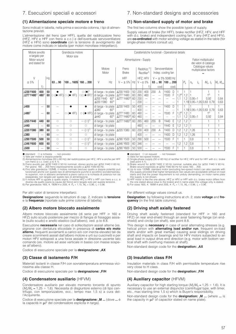
57
7. Esecuzioni speciali e accessori 7. Non-standard designs and accessories
(1) Alimentazione speciale motore e frenoSono indicati in tabella, nella prima e seconda colonna, i tipi di alimen-tazione previsti.L’alimentazione del freno (per HFF), quella del raddrizzatore freno(HFZ, HFV e HFF con freno a c.c.) e dell’eventuale servoventilatore(HFZ e HFV) sono coordinate con la tensione di avvolgimento delmotore come indicato in tabella (per motori monofase interpellarci).
(1) Non-standard supply of motor and brakeThe first two columns show the possible types of supply.Supply values of brake (for HFF), brake rectifier (HFZ, HFV, and HFFwith d.c. brake) and independent cooling fan, if any (HFZ and HFV),are co-ordinated with motor winding voltage as stated in the table (forsingle-phase motors consult us).
Per altri valori di tensione interpellarci.Designazione: seguendo le istruzioni di cap. 2, indicare la tensionee la frequenza (riportate sulle prime colonne di tabella).
(2) Albero motore bloccato assialmenteAlbero motore bloccato assialmente (di serie per HFF 160 eHFZ) sullo scudo posteriore per mezzo di flangia di fissaggio assia-le (sullo scudo) e anello elastico (sull’albero), ved. p.to 8.8.Esecuzione necessaria nel caso di sollecitazioni assiali alterne (es.pignone con dentatura elicoidale in presenza di carico e/o motoalterno, frequenti avviamenti a carico e/o con inerzie elevate) tali dacreare scorrimenti assiali dall’albero motore e urti sui cuscinetti e permotori HFV sottoposti a una forza assiale in direzione uscente latocomando (es. motore ad asse verticale in basso con masse sospe-se all’albero).Codice di esecuzione speciale per la designazione: ,AX
(3) Classe di isolamento F/HMateriali isolanti in classe F/H con sovratemperatura ammessa vici-nissima alla classe H.Codice di esecuzione speciale per la designazione: ,F/H
(4) Condensatore ausiliario (HFVM)Condensatore ausiliario per elevato momento torcente di spunto(Ms/MN ≈ 1,25 1,6). Necessita di disgiuntore esterno (di tipo cen-trifugo, con temporizzatore, ecc.; tempo max 1,5 s) a cura del-l’Acquirente.Codice di esecuzione speciale per la designazione: ,M ... (dove ... èla capacità in F del condensatore esplicita in targa).
For different voltage values consult us.Designation: by following instructions at ch. 2, state voltage and fre-quency (in the first table columns).
(2) Driving shaft axially fastenedDriving shaft axially fastened (standard for HFF 160 andHFZ) on rear end-shield through an axial fastening flange (on end-shield) and circlip (on shaft), see point 8.8.This design is necessary in case of axial alternating stresses (e.g.helical pinion with alternating load and/or run, frequent on-loadstarts and/or with great inertiae) causing axial slidings on drivingshaft and impacts on bearings and for HFV motors subjected to anaxial load in output drive end direction (e.g. motor with bottom ver-tical shaft with overhung masses at shaft).Non-standard design code for the designation: ,AX
(3) Insulation class F/HInsulation materials in class F/H with permissible temperature risevery close to H class.Non-standard design code for the designation: ,F/H
(4) Auxiliary capacitor (HFVM)Auxiliary capacitor for high starting torque (Ms/MN ≈ 1,25 1,6). It isnecessary to use an external disjunctor (centrifugal type, with timer,etc., max starting time 1,5 s) which is Buyer’s responsibility.Non-standard design code for the designation: ,M ... (where ... isthe capacity in F of capacitor stated on name plate).
Motore avvoltoe targato perMotor woundand stated for
Grandezza motoreMotor size
Caratteristiche funzionali - Operational details
Alimentazione - Supply
MotoreMotor
FrenoBrake
Raddrizz.2)
Rectifier2)
ServoventilatoreIndep. cooling fan
Fattori moltiplicatividei valori di catalogo
Catalogue valuesmultiplicative factors
≈
V Hz HFF HFZ, HFV V ~ ± 5% 50/60 Hz± 5% 63 ... 90 100 ... 160S 160 ... 200 V Hz V ~ ± 5% Hz V ~± 5% 63 ... 90 100 ... 200 PN nN IN MN, IS MS, Mmax
1) 1) cod. cod.
230 Y400 400 50 ()1) di targa - to plate 230 Y400 50 230 400 230 A Y400 D 1 1 1 1 1277 Y4805) 4805) 60 ( HFF) ( HFF) (, HFF)1) di targa - to plate 277 Y480 60 265 460 – – Y500 F 1,26) 1,2 1 16) 1
255 Y440 604) 277 Y4803) 60 230 – – – – – 1,1 1,2 0,95÷1 0,92 0,84220 Y380 604) – – 230 – – – – – 1 1,19 0,95÷1,05 0,83 0,79 0,63
400 – 50 – di targa - to plate 230 Y400 50 400 – – – Y400 D 1 1 1 1 1380 604) – – 400 – – – – – 1 1,19 0,95÷1,05 0,83 0,79 0,63
4805) – 60 – ( HFF) ( HFF) di targa - to plate 277 Y480 60 460 – – – Y500 F 1,26) 1,2 1 16) 1440 604) 277 Y4803) 60 460 – – – – – 1,1 1,2 0,95÷1 0,92 0,84
255 Y440 440 60 – ()1) di targa - to plate 277 Y4803) 60 265 460 255 B Y440 E 1,2 1,2 1 1 1440 – 60 – di targa - to plate 460 – – – Y440 E 1,2 1,2 1 1 1220 Y380 380 60 – ()1) di targa - to plate 220 Y380 60 230 400 230 A Y400 D 1,2 1,2 1,26 1 1380 – 60 – di targa - to plate 400 – – – Y400 D 1,2 1,2 1,26 1 1290 Y500 500 50 – ()1) di targa - to plate 290 Y500 50 290 500 – – Y500 F 1 1 0,8 1 1346 Y600 600 60 – ()1) di targa - to plate 346 Y600 60 346 – – – – – 1,2 1,2 0,8 1 1500 – 50 – di targa - to plate 290 Y600 50 500 – – – Y500 F 1 1 0,8 1 1
standard a richiesta – non previsto1) Vale per motori a doppia polarità.2) Alimentazione monofase (50 o 60 Hz) del raddrizzatore per HFZ, HFV e anche per HFF
con freno a c.c. (ved. p.to 4.1).3) Freno avvolto per 230 Y400 V 50 Hz nominali, idoneo anche per 255 Y440 V 60 Hz.
Per grand. 160 ... 200 freno espressamente avvolto a 255 Y440 60 Hz.4) Fino alla grandezza 132MB, il motore normale (escluso quello a doppia polarità) può
funzionare anche con questo tipo di alimentazione purché si accettino sovratemperatu-re superiori, non si abbiano avviamenti a pieno carico e la richiesta di potenza non siaesasperata; non targato per questo tipo di alimentazione.
5) Il motore HFF è uguale a quello sopra, il motore HFZ o HFV o HFF con freno a c.c. èdiverso da quello sopra (a causa del freno) ed è targato solo per questa tensione.
6) Per grandezze 160L 4, 180M 4 e 200L 4: PN = 1,15, MN = 0,96, Is = 0,96.
standard on request – not foreseen1) Valid for two-speed motors.2) Single-phase supply (50 or 60 Hz) of rectifier for HFZ, HFV and for HFF with d.c. brake
(see point 4.1).3) Brake wound for 230 Y400 V 50 Hz nominal, suitable also for 255 Y440 V 60 Hz.
Brake wound expressly at 255 Y440 60 Hz for sizes 160 ... 200.4) Up to size 132MB, standard motor (excluding two-speed motor) can also operate with
this supply provided that higher temperature rise values are acceptable without on-loadstarts and that the power requirement is not unduly demanding; on motor name platethis supply is not shown.
5) HFF motor is like the one above, HFZ or HFV or HFF with d.c. brake motor differs fromthe one stated above (due to the brake) and in name plate this voltage only is stated.
6) For sizes 160L 4, 180M 4 and 200L 4: PN = 1,15, MN = 0,96, Is = 0,96.
58
7.Esecuzioni speciali e accessori 7. Non-standard designs and accessories
(5) Condensatore ausiliario con disgiuntore elet-tronico (HFVM)Condensatore ausiliario per elevato momento torcente di spunto(Ms/MN ≈ 1,25 1,6) che dopo 1,5 s dall’avviamento del motore sidisinserisce automaticamente per mezzo di un disgiuntore elettroni-co incorporato (non necessita quindi di disgiuntore esterno). Nonidoneo per applicazioni con tempo di avviamento 1,5 s.Tra un avviamento e il successivo è necessario un tempo di 6 s; nonadatto per marcia a impulsi.Codice di esecuzione speciale per la designazione: ,E ... (dove ... èla capacità in F del condensatore esplicita in targa).
(6) Due avvolgimenti separati (4.6 e 6.8 poli)Motore con due avvolgimenti separati.Per caratteristiche funzionali ved. p.ti 4.2, 5.2, 6.2.Codice di esecuzione speciale per la designazione: ,YY
(7) Esecuzione per basse temperature (-30 °C)(HFZ, HFV)I motori in esecuzione standard possono funzionare a temperaturaambiente fino a -15 °C, con punte anche fino a -20 °C.Per temperatura ambiente fino a -30 °C grand. 63 ... 160S: cuscinettispeciali, ventola di lega leggera (di ghisa per HFV), pressacavi etappi metallici.Se ci sono pericoli di formazione di condensa, è consigliabile richie-dere anche l’«Esecuzione per ambiente umido e corrosivo» (47) (dis-ponibile solo per HFZ) ed eventualmente, «Fori scarico condensa»(8) e/o «Scaldiglia anticondensa» (13).Per temperatura ambiente fino a -30 °C grand. 160 ... 200: cuscinetticon grasso speciale, pressacavi e tappi metallici, trattamento perambiente umido e corrosivo di statore e albero con rotore, fori sca-rico condensa e scaldiglia anticondensa.Se ci sono pericoli di formazione di ghiaccio sulla guarnizione d’attri-to interpellarci.Con esecuzioni (17), (18) e (36) interpellarci.Non possibile con esecuzione «Volano» (23) per HFZ grand. 63 e 71.Codice di esecuzione speciale per la designazione: ,BT
(8) Fori scarico condensaNella designazione motore indicare in «FORMA COSTRUTTIVA» ladesignazione della reale forma costruttiva di impiego che determinala posizione dei fori e sarà riportata anche in targa.I motori vengono consegnati con i fori chiusi da tappi.Codice di esecuzione speciale per la designazione: ,CD
(9) Impregnazione supplementare avvolgimentiConsiste in un secondo ciclo di impreganzione a pacco statore finito.Utile quando si voglia una protezione (degli avvolgimenti) superioreal normale da agenti elettrici (picchi di tensione da rapide commu-tazioni o da inverter «scadenti» con elevati gradienti di tensione) omeccanici (vibrazioni meccaniche o elettromagnetiche indotte: es.da inverter). Ved. anche cap. 3.7 pag. 16 “Picchi di tensione (Umax),gradienti di tensione (dU/dt), lunghezza cavi”.Codice di esecuzione speciale per la designazione: ,SP
(10) Motore per alimentazione 230.460 V 60 Hz(a singola polarità, grand. 63 ... 160S)Motori trifase grandezze 63 ... 90 con morsettiera a 9 morsetti adat-ti ad essere alimentati a 60 Hz con le seguenti tensioni (e relativeconnessioni degli avvolgimenti):230 V 60 Hz per collegamento YY460 V 60 Hz per collegamento YMotori trifase grandezze 100 ... 160S con morsettiera a 12 morsettiadatti ad essere alimentati a 60 Hz con le seguenti tensioni (e rela-tive connessioni degli avvolgimenti):230 V 60 Hz per collegamento 460 V 60 Hz per collegamento 400 V 60 Hz per collegamento YYcon collegamento Y utilizzabile solo a 460 V 60 Hz per avviamento Y.L’alimentazione del raddrizzatore (motori HFZ, HFV, HFF con freno inc.c.) è prevista per la tensione d’alimentazione più bassa fra quellepossibili. Per motore HFF l’alimentazione è indifferentemente unadelle due con l’opportuno collegamento (230 o Y460 V).I motori destinati agli Stati Uniti debbono essere normalmente inquesta esecuzione.A richiesta sono possibili altre tensioni sempre in rapporto 1 a 2.
Nella designazione indicare (in «ALIMENTAZIONE»): 230.460-60
(5) Auxiliary capacitor with electronic disjunctor(HFVM)Auxiliary capacitor for high starting torque (Ms/MN ≈ 1,25 1,6) thatafter 1,5 s from motor starting, automatically disconnects through anincorporated electronic disjunctor (no external disjunctor is necessary).Not suitable for applications with starting time 1,5 s.Between two starting a stop time of 6 s is necessary; not suitable forjogging.Non-standard design code for the designation: ,E ... (where ... is thecapacity in F of the capacitor stated on name plate).
(6) Two separate windings (4.6 and 6.8 poles)Motor with two separate windings.For functional specifications see points 4.2, 5.2, 6.2.Non-standard design code for the designation: ,YY
(7) Design for low temperatures (-30 °C)(HFZ, HFV)Standard motors can operate for possible ambient temperature upto -15 °C, and transitorily up to -20 °C.For ambient temperature down to -30 °C sizes 63 ... 160S: specialbearings, light alloy fan (cast iron for HFV), cable glands and metalplugs.If there are dangers of condensate, it is advisable to require also«Design for damp and corrosive environments» (47) (available forHFZ, only) and, if necessary, the design «Condensate drain holes»(8) and/or «Anti-condensation heater» (13).For ambient temperature down to -30 °C sizes 160 ... 200: bearingswith special grease, cable glands and metal plugs, treatment fordamp and corrosive environment of stator and shaft with rotor, con-densate drain holes and anti-condensation heater.May there be dangers of ice on friction surface consult us.With designs (17), (18) and (36), consult us.Not possible with design «Flywheel»(23) for HFZ sizes 63 and 71.Non-standard design code for the designation: ,BT
(8) Condensate drain holesIn motor designation state in «MOUNTING POSITION» the designa-tion of the real application mounting position, determining the holeposition, which will also appear on name plate.Motors are supplied with holes closed by plugs.Non-standard design code for the designation: ,CD
(9) Additional windings impregnationIf consists of a second impregnation cycle after stator winding assembling.Useful where it is necessary to have an additional protection (of thewindings) against electrical stress (voltage peaks due to rapid com-mutations or to «low quality» inverters with high voltage gradients)or mechanical agents (mechanical or electromagnetic vibrations:e.g. from inverter). See also ch. 3.7, page 16 «Voltage, peaks (Umax),voltage gradients (dU/dt), cable length».Non-standard design code for the designation: ,SP
(10) Motor for supply 230.460 V 60 Hz(single-speed, size 63 ... 160S)Three-phase motor sizes 63 ... 90 with terminal block with 9 termi-nals suitable for 60 Hz supply having following voltages (and rele-vant winding connections):230 V 60 Hz for YY connection460 V 60 Hz for Y connectionThree-phase motor sizes 100 ... 160S with terminal block with 12terminals suitable for 60 Hz supply having following voltages (andrelevant winding connections):230 V 60 Hz for connection460 V 60 Hz for connection400 V 60 Hz for YY connectionwith Y connection for use only at 460 V 60 Hz with Y starting.The rectifier voltage (motor HFZ, HFV, HFF with d.c. brake) is fore-seen for the lowest possible supply voltage of motor. For HFF motorthe supply can indifferently be one of the two with proper connection(230 or Y460 V).Motors for the USA must be usually supplied in this design.On request other voltages always in ratio 1 to 2 are possible.
In the designation («SUPPLY») state: 230.460-60
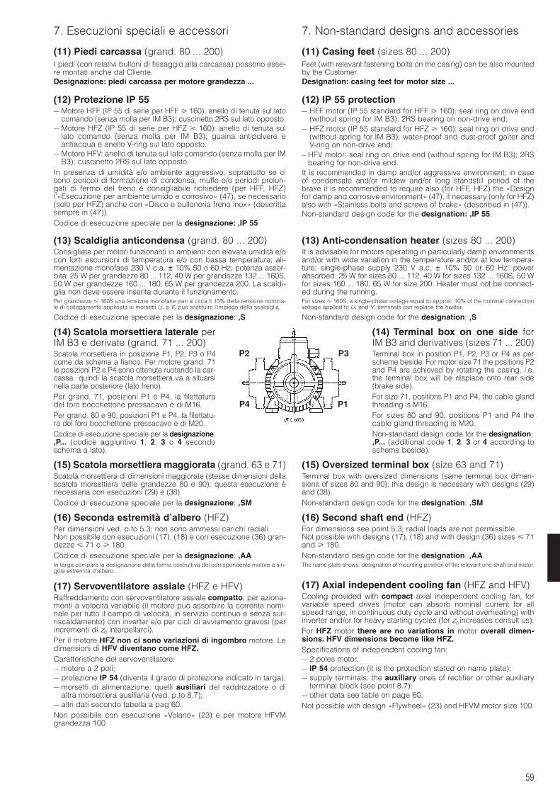
59
7. Esecuzioni speciali e accessori 7. Non-standard designs and accessories
(11) Piedi carcassa (grand. 80 ... 200)I piedi (con relativi bulloni di fissaggio alla carcassa) possono esse-re montati anche dal Cliente.Designazione: piedi carcassa per motore grandezza ...
(12) Protezione IP 55– Motore HFF (IP 55 di serie per HFF 160): anello di tenuta sul lato
comando (senza molla per IM B3); cuscinetto 2RS sul lato opposto.– Motore HFZ (IP 55 di serie per HFZ 160): anello di tenuta sul
lato comando (senza molla per IM B3); guaina antipolvere eantiacqua e anello V-ring sul lato opposto.
– Motore HFV: anello di tenuta sul lato comando (senza molla per IMB3); cuscinetto 2RS sul lato opposto.
In presenza di umidità e/o ambiente aggressivo, soprattutto se cisono pericoli di formazione di condensa, muffe e/o periodi prolun-gati di fermo del freno è consigliabile richiedere (per HFF, HFZ)l’«Esecuzione per ambiente umido e corrosivo» (47), se necessario(solo per HFZ) anche con «Disco e bulloneria freno inox» (descrittasempre in (47)).Codice di esecuzione speciale per la designazione: ,IP 55
(13) Scaldiglia anticondensa (grand. 80 ... 200)Consigliata per motori funzionanti in ambienti con elevata umidità e/ocon forti escursioni di temperatura e/o con bassa temperatura; ali-mentazione monofase 230 V c.a. ± 10% 50 o 60 Hz; potenza assor-bita: 25 W per grandezze 80 ... 112, 40 W per grandezze 132 ... 160S,50 W per grandezze 160 ... 180, 65 W per grandezza 200. La scaldi-glia non deve essere inserita durante il funzionamento.Per grandezze 160S una tensione monofase pari a circa il 10% della tensione nomina-le di collegamento applicata ai morsetti U1 e V1 può sostituire l’impiego della scaldiglia.
Codice di esecuzione speciale per la designazione: ,S
(14) Scatola morsettiera laterale perIM B3 e derivate (grand. 71 ... 200)Scatola morsettiera in posizione P1, P2, P3 o P4come da schema a fianco. Per motore grand. 71le posizioni P2 e P4 sono ottenute ruotando la car-cassa quindi la scatola morsettiera va a situarsinella parte posteriore (lato freno).Per grand. 71, posizioni P1 e P4, la filettaturadel foro bocchettone pressacavo è di M16.Per grand. 80 e 90, posizioni P1 e P4, la filettatu-ra del foro bocchettone pressacavo è di M20.Codice di esecuzione speciale per la designazione:,P... (codice aggiuntivo 1, 2, 3 o 4 secondoschema a lato).
(15) Scatola morsettiera maggiorata (grand. 63 e 71)Scatola morsettiera di dimensioni maggiorate (stesse dimensioni dellascatola morsettiera delle grandezze 80 e 90); questa esecuzione ènecessaria con esecuzioni (29) e (38).Codice di esecuzione speciale per la designazione: ,SM
(16) Seconda estremità d’albero (HFZ)Per dimensioni ved. p.to 5.3; non sono ammessi carichi radiali.Non possibile con esecuzioni (17), (18) e con esecuzione (36) gran-dezze 71 e 180.Codice di esecuzione speciale per la designazione: ,AAIn targa compare la designazione della forma costruttiva del corrispondente motore a sin-gola estremità d’albero.
(17) Servoventilatore assiale (HFZ e HFV)Raffreddamento con servoventilatore assiale compatto, per aziona-menti a velocità variabile (il motore può assorbire la corrente nomi-nale per tutto il campo di velocità, in servizio continuo e senza sur-riscaldamento) con inverter e/o per cicli di avviamento gravosi (perincrementi di z0 interpellarci).Per il motore HFZ non ci sono variazioni di ingombro motore. Ledimensioni di HFV diventano come HFZ.Caratteristiche del servoventilatore:– motore a 2 poli;– protezione IP 54 (diventa il grado di protezione indicato in targa);– morsetti di alimentazione: quelli ausiliari del raddrizzatore o di
altra morsettiera ausiliaria (ved. p.to 8.7);– altri dati secondo tabella a pag 60.Non possibile con esecuzione «Volano» (23) e per motore HFVMgrandezza 100.
(11) Casing feet (sizes 80 ... 200)Feet (with relevant fastening bolts on the casing) can be also mountedby the Customer.Designation: casing feet for motor size ...
(12) IP 55 protection– HFF motor (IP 55 standard for HFF 160): seal ring on drive end
(without spring for IM B3); 2RS bearing on non-drive end;– HFZ motor (IP 55 standard for HFZ 160): seal ring on drive end
(without spring for IM B3); water-proof and dust-proof gaiter andV-ring on non-drive end;
– HFV motor: seal ring on drive end (without spring for IM B3); 2RSbearing for non-drive end.
It is recommended in damp and/or aggressive environment; in caseof condensate and/or mildew and/or long standstill period of thebrake it is recommended to require also (for HFF, HFZ) the «Designfor damp and corrosive environment» (47), if necessary (only for HFZ)also with «Stainless bolts and screws of brake» (described in (47)).Non-standard design code for the designation: ,IP 55.
(13) Anti-condensation heater (sizes 80 ... 200)It is advisable for motors operating in particularly damp environmentsand/or with wide variation in the temperature and/or at low tempera-ture; single-phase supply 230 V a.c. ± 10% 50 or 60 Hz; powerabsorbed: 25 W for sizes 80 ... 112, 40 W for sizes 132 ... 160S, 50 Wfor sizes 160 ... 180, 65 W for size 200. Heater must not be connect-ed during the running.For sizes 160S, a single-phase voltage equal to approx. 10% of the nominal connectionvoltage applied to U1 and V1 terminals can replace the heater.
Non-standard design code for the designation: ,S
(14) Terminal box on one side forIM B3 and derivatives (sizes 71 ... 200)Terminal box in position P1, P2, P3 or P4 as perscheme beside. For motor size 71 the positions P2and P4 are achieved by rotating the casing, i.e.the terminal box will be displace onto rear side(brake side).For size 71, positions P1 and P4, the cable glandthreading is M16.For sizes 80 and 90, positions P1 and P4 thecable gland threading is M20.Non-standard design code for the designation:,P... (additional code 1, 2, 3 or 4 according toscheme beside).
(15) Oversized terminal box (size 63 and 71)Terminal box with oversized dimensions (same terminal box dimen-sions of sizes 80 and 90); this design is necessary with designs (29)and (38).Non-standard design code for the designation: ,SM
(16) Second shaft end (HFZ)For dimensions see point 5.3; radial loads are not permissible.Not possible with designs (17), (18) and with design (36) sizes 71and 180.Non-standard design code for the designation: ,AAThe name plate shows: designation of mounting position of the relevant one-shaft end motor.
(17) Axial independent cooling fan (HFZ and HFV)Cooling provided with compact axial independent cooling fan, forvariable speed drives (motor can absorb nominal current for allspeed range, in continuous duty cycle and without overheating) withinverter and/or for heavy starting cycles (for z0 increases consult us).For HFZ motor there are no variations in motor overall dimen-sions. HFV dimensions become like HFZ.Specifications of independent cooling fan:– 2 poles motor;– IP 54 protection (it is the protection stated on name plate);– supply terminals: the auxiliary ones of rectifier or other auxiliary
terminal block (see point 8.7);– other data see table on page 60.Not possible with design «Flywheel» (23) and HFVM motor size 100.
P1
P2
P4
P3
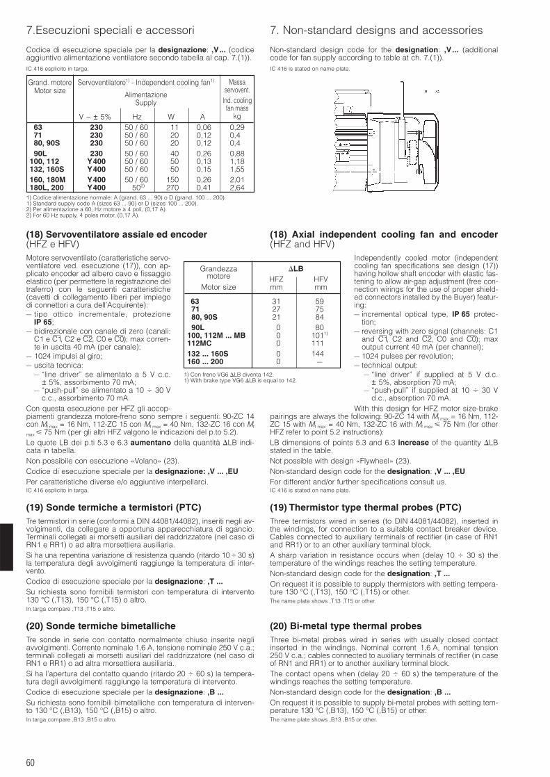
60
7.Esecuzioni speciali e accessori 7. Non-standard designs and accessories
Codice di esecuzione speciale per la designazione: ,V... (codiceaggiuntivo alimentazione ventilatore secondo tabella al cap. 7.(1)).IC 416 esplicito in targa.
(18) Servoventilatore assiale ed encoder(HFZ e HFV)Motore servoventilato (caratteristiche servo-ventilatore ved. esecuzione (17)), con ap-plicato encoder ad albero cavo e fissaggioelastico (per permettere la registrazione deltraferro) con le seguenti caratteristiche(cavetti di collegamento liberi per impiegodi connettori a cura dell’Acquirente):– tipo ottico incrementale, protezione
IP 65;– bidirezionale con canale di zero (canali:
C1 e C1—, C2 e C2—, C0 e C0—); max corren-te in uscita 40 mA (per canale);
– 1024 impulsi al giro;– uscita tecnica:
– “line driver” se alimentato a 5 V c.c.± 5%, assorbimento 70 mA;
– “push-pull” se alimentato a 10 30 Vc.c., assorbimento 70 mA.
Con questa esecuzione per HFZ gli accop-piamenti grandezza motore-freno sono sempre i seguenti: 90-ZC 14con Mf max = 16 Nm, 112-ZC 15 con Mf max = 40 Nm, 132-ZC 16 con Mf
max 75 Nm (per gli altri HFZ valgono le indicazioni del p.to 5.2).Le quote LB dei p.ti 5.3 e 6.3 aumentano della quantità LB indi-cata in tabella.Non possibile con esecuzione «Volano» (23).Codice di esecuzione speciale per la designazione: ,V ... ,EUPer caratteristiche diverse e/o aggiuntive interpellarci.IC 416 esplicito in targa.
(19) Sonde termiche a termistori (PTC)Tre termistori in serie (conformi a DIN 44081/44082), inseriti negli av-volgimenti, da collegare a opportuna apparecchiatura di sgancio.Terminali collegati ai morsetti ausiliari del raddrizzatore (nel caso diRN1 e RR1) o ad altra morsettiera ausiliaria.Si ha una repentina variazione di resistenza quando (ritardo 1030 s)la temperatura degli avvolgimenti raggiunge la temperatura di inter-vento.Codice di esecuzione speciale per la designazione: ,T ...Su richiesta sono fornibili termistori con temperatura di intervento130 °C (,T13), 150 °C (,T15) o altro.In targa compare ,T13 ,T15 o altro.
(20) Sonde termiche bimetallicheTre sonde in serie con contatto normalmente chiuso inserite negliavvolgimenti. Corrente nominale 1,6 A, tensione nominale 250 V c.a.;terminali collegati ai morsetti ausiliari del raddrizzatore (nel caso diRN1 e RR1) o ad altra morsettiera ausiliaria.Si ha l’apertura del contatto quando (ritardo 20 60 s) la tempera-tura degli avvolgimenti raggiunge la temperatura di intervento.Codice di esecuzione speciale per la designazione: ,B ...Su richiesta sono fornibili bimetalliche con temperatura di interven-to 130 °C (,B13), 150 °C (,B15) o altro.In targa compare ,B13 ,B15 o altro.
Non-standard design code for the designation: ,V... (additionalcode for fan supply according to table at ch. 7.(1)).IC 416 is stated on name plate.
(18) Axial independent cooling fan and encoder(HFZ and HFV)
Independently cooled motor (independentcooling fan specifications see design (17))having hollow shaft encoder with elastic fas-tening to allow air-gap adjustment (free con-nection wirings for the use of proper shield-ed connectors installed by the Buyer) featur-ing:– incremental optical type, IP 65 protec-
tion;– reversing with zero signal (channels: C1
and C1—, C2 and C2—, C0 and C0—); maxoutput current 40 mA (per channel);
– 1024 pulses per revolution;– technical output:
– “line driver” if supplied at 5 V d.c.± 5%, absorption 70 mA;
– “push-pull” if supplied at 10 30 Vd.c., absorption 70 mA.
With this design for HFZ motor size-brakepairings are always the following: 90-ZC 14 with Mf max = 16 Nm, 112-ZC 15 with Mf max = 40 Nm, 132-ZC 16 with Mf max 75 Nm (for otherHFZ refer to point 5.2 instructions):LB dimensions of points 5.3 and 6.3 increase of the quantity LBstated in the table.Not possible with design «Flywheel» (23).Non-standard design code for the designation: ,V ... ,EUFor different and/or further specifications consult us.IC 416 is stated on name plate.
(19) Thermistor type thermal probes (PTC)Three termistors wired in series (to DIN 44081/44082), inserted inthe windings, for connection to a suitable contact breaker device.Cables connected to auxiliary terminals of rectifier (in case of RN1and RR1) or to an other auxiliary terminal block.A sharp variation in resistance occurs when (delay 10 30 s) thetemperature of the windings reaches the setting temperature.Non-standard design code for the designation: ,T ...On request it is possible to supply thermistors with setting tempera-ture 130 °C (,T13), 150 °C (,T15) or other.The name plate shows ,T13 ,T15 or other.
(20) Bi-metal type thermal probesThree bi-metal probes wired in series with usually closed contactinserted in the windings. Nominal corrent 1,6 A, nominal tension250 V c.a.; cables connected to auxiliary terminals of rectifier (in caseof RN1 and RR1) or to another auxiliary terminal block.The contact opens when (delay 20 60 s) the temperature of thewindings reaches the setting temperature.Non-standard design code for the designation: ,B ...On request it is possible to supply bi-metal probes with setting tem-perature 130 °C (,B13), 150 °C (,B15) or other.The name plate shows ,B13 ,B15 or other.
Grandezza LBmotore HFZ HFV
Motor size mm mm
63 31 591)
71 27 751)
80, 90S 21 841)
90L 0 801)
100, 112M ... MB 0 1011)
112MC 0 1111)
132 ... 160S 0 1441)
160 ... 200 0 –
1) Con freno VG6 LB diventa 142.1) With brake type VG6 LB is equal to 142.
Grand. motore Servoventilatore1) - Independent cooling fan1)
Motor size AlimentazioneSupply
V ~ ± 5% Hz W A63 230 50 / 602) 11 0,06 0,2971 230 50 / 602) 20 0,12 0,480, 90S 230 50 / 602) 20 0,12 0,490L 230 50 / 602) 40 0,26 0,88
100, 112 Y400 50 / 602) 50 0,13 1,18132, 160S Y400 50 / 602) 50 0,15 1,55160, 180M Y400 50 / 602) 150 0,26 2,01180L, 200 Y400 502) 270 0,41 2,64
1) Codice alimentazione normale: A (grand. 63 ... 90) o D (grand. 100 ... 200).1) Standard supply code A (sizes 63 ... 90) or D (sizes 100 ... 200).2) Per alimentazione a 60, Hz motore a 4 poli, (0,17 A).2) For 60 Hz supply, 4 poles motor, (0,17 A).
Massaservovent.
Ind. coolingfan mass
kg
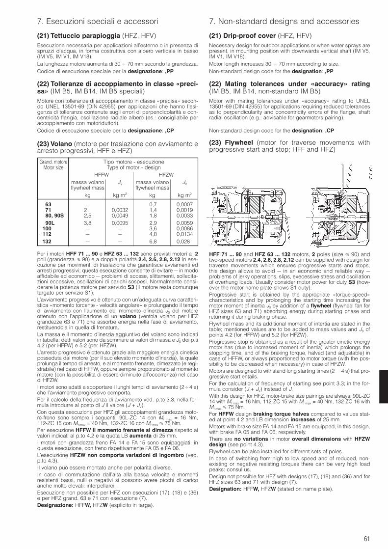
61
7. Esecuzioni speciali e accessori 7. Non-standard designs and accessories
(21) Tettuccio parapioggia (HFZ, HFV)Esecuzione necessaria per applicazioni all’esterno o in presenza dispruzzi d’acqua, in forma costruttiva con albero verticale in basso(IM V5, IM V1, IM V18).La lunghezza motore aumenta di 30 70 mm secondo la grandezza.Codice di esecuzione speciale per la designazione: ,PP
(22) Tolleranze di accoppiamento in classe «preci-sa» (IM B5, IM B14, IM B5 speciali)Motore con tolleranze di accoppiamento in classe «precisa» secon-do UNEL 13501-69 (DIN 42955) per applicazioni che hanno l’esi-genza di tolleranze contenute sugli errori di perpendicolarità e con-centricità flangia, oscillazione radiale albero (es.: consigliabile peraccoppiamento con motoriduttori).Codice di esecuzione speciale per la designazione: ,CP
(23) Volano (motore per traslazione con avviamento earresto progressivi; HFF e HFZ)
(21) Drip-proof cover (HFZ, HFV)Necessary design for outdoor applications or when water sprays arepresent, in mounting position with downwards vertical shaft (IM V5,IM V1, IM V18).Motor length increases 30 70 mm according to size.Non-standard design code for the designation: ,PP
(22) Mating tolerances under «accuracy» rating(IM B5, IM B14, non-standard IM B5)Motor with mating tolerances under «accuracy» rating to UNEL13501-69 (DIN 42955) for applications requiring reduced tolerancesas to perpendicularity and concentricity errors of the flange, shaftradial oscillation (e.g.: advisable for gearmotors pairing).
Non-standard design code for the designation: ,CP
(23) Flywheel (motor for traverse movements withprogressive start and stop; HFF and HFZ)
Grand. motore Tipo motore - esecuzioneMotor size Type of motor - design
HFFW HFZWmassa volano JV massa volano JVflywheel mass flywheel mass
kg kg m2 kg kg m2
63 – – 0,7 0,000771 2,5 0,0032 1,4 0,001980, 90S 2,5 0,0049 1,8 0,003390L 3,8 0,0095 2,9 0,0059
100 – – 3,6 0,0086112 – – 4,8 0,0134132 – – 6,8 0,0280
Per i motori HFF 71 ... 90 e HFZ 63 ... 132 sono previsti motori a 2poli (grandezza 90) e a doppia polarità 2.4, 2.6, 2.8, 2.12 in ese-cuzione per movimenti di traslazione che garantisce avviamenti edarresti progressivi; questa esecuzione consente di evitare – in modoaffidabile ed economico – problemi di scosse, slittamenti, sollecita-zioni eccessive, oscillazioni di carichi sospesi. Normalmente consi-derare la potenza motore per servizio S3 (il motore resta comunquetargato per servizio S1).L’avviamento progressivo è ottenuto con un’adeguata curva caratteri-stica «momento torcente - velocità angolare» e prolungando il tempodi avviamento con l’aumento del momento d’inerzia J0 del motoreottenuto con l’applicazione di un volano (ventola volano per HFZgrandezze 63 e 71) che assorbe energia nella fase di avviamento,restituendola in quella di frenatura.La massa e il momento d’inerzia aggiuntivo del volano sono indicatiin tabella; detti valori sono da sommare ai valori di massa e J0 dei p.ti4.2 (per HFFW) e 5.2 (per HFZW).L’arresto progressivo è ottenuto grazie alla maggiore energia cineticaposseduta dal motore (per il suo elevato momento d’inerzia), la qualeprolunga il tempo di arresto, e al momento frenante, dimezzato (e regi-strabile) nel caso di HFFW, oppure sempre proporzionato al momentomotore (con la possibilità di essere diminuito all’occorrenza) nel casodi HFZW.I motori sono adatti a sopportare i lunghi tempi di avviamento (24 s)che l’avviamento progressivo comporta.Per il calcolo della frequenza di avviamento ved. p.to 3.3; nella for-mula introdurre al posto di J il valore (J + JV).Con questa esecuzione per HFZ gli accoppiamenti grandezza moto-re-freno sono sempre i seguenti: 90L-ZC 14 con M f max = 16 Nm,112-ZC 15 con Mf max = 40 Nm, 132-ZC 16 con Mf max 75 Nm.Per esecuzione HFFW il momento frenante si dimezza rispetto aivalori indicati al p.to 4.2 e la quota LB aumenta di 25 mm.I motori con grandezza freno FA 14 e FA 15 sono equipaggiati, inquesta esecuzione, con freno rispettivamente FA 05 e FA 06.L’esecuzione HFZW non comporta variazioni di ingombro (ved.p.to 4.3).Il volano può essere montato anche per polarità diverse.In caso di commutazione dall’alta alla bassa velocità e momentiresistenti bassi, nulli o negativi si possono avere picchi di caricoanche molto elevati: interpellarci.Esecuzione non possibile per HFZ con esecuzioni (17), (18) e (36)e per HFZ grand. 63 e 71 con esecuzione (7).Designazione: HFFW, HFZW (esplicito in targa).
HFF 71 ... 90 and HFZ 63 ... 132 motors, 2 poles (size 90) andtwo-speed motors 2.4, 2.6, 2.8, 2.12 can be supplied with design fortraverse movements which ensures progressive starts and stops;this design allows to avoid – in an economic and reliable way –problems of jerky operations, slips, execessive stress and oscillationof overhung loads. Usually consider motor power for duty S3 (how-ever the motor name plate shows S1 duty).Progressive start is obtained by the appropriate «torque-speed»characteristics and by prolonging the starting time increasing themotor moment of inertia J0 by addition of a flywheel (flywheel fan forHFZ sizes 63 and 71) absorbing energy during starting phase andreturning it during braking phase.Flywheel mass and its additional moment of intertia are stated in thetable; mentioned values are to be added to mass values and J0 ofpoints 4.2 (for HFFW) and 5.2 (for HFZW).Progressive stop is obtained as a result of the greater cinetic energymotor has (due to increased moment of inertia) which prolongs thestopping time, and of the braking torque, halved (and adjustable) incase of HFFW, or always proportioned to motor torque (with the pos-sibility to be decreased when necessary) in case of HFZW.Motors are designed to withstand long starting times (2 4 s) that pro-gressive start entails.For the calculation of frequency of starting see point 3.3; in the for-mula consider (J + JV) instead of J.With this design for HFZ, motor-brake size pairings are always: 90L-ZC14 with Mf max = 16 Nm, 112-ZC 15 with Mf max = 40 Nm, 132-ZC 16 withMf max 75 Nm.For HFFW design braking torque halves compared to values stat-ed at point 4.2 and LB dimension increases of 25 mm.Motors with brake size FA 14 and FA 15 are equipped, in this design,with brake FA 05 and FA 06, respecively.There are no variations in motor overall dimensions with HFZWdesign (see point 4.3).Flywheel can be also installed for different sets of poles.In case of switching from high to low speed and of reduced, non-existing or negative resisting torques there can be very high loadpeaks: consul us.Design not possible for HFZ with designs (17), (18) and (36) and forHFZ sizes 63 and 71 with design (7).Designation: HFFW, HFZW (stated on name plate).
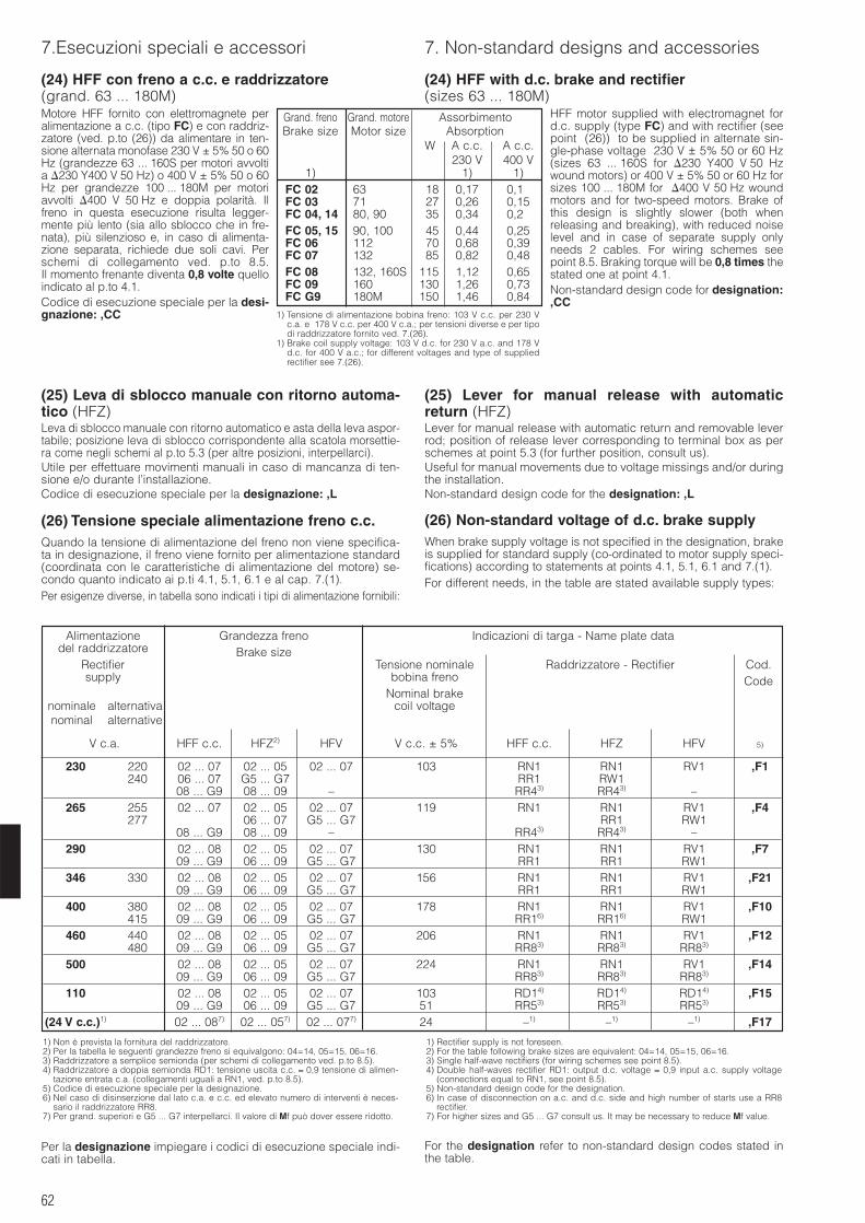
62
7.Esecuzioni speciali e accessori 7. Non-standard designs and accessories
(24) HFF con freno a c.c. e raddrizzatore(grand. 63 ... 180M)Motore HFF fornito con elettromagnete peralimentazione a c.c. (tipo FC) e con raddriz-zatore (ved. p.to (26)) da alimentare in ten-sione alternata monofase 230 V ± 5% 50 o 60Hz (grandezze 63 ... 160S per motori avvoltia 230 Y400 V 50 Hz) o 400 V ± 5% 50 o 60Hz per grandezze 100 ... 180M per motoriavvolti 400 V 50 Hz e doppia polarità. Ilfreno in questa esecuzione risulta legger-mente più lento (sia allo sblocco che in fre-nata), più silenzioso e, in caso di alimenta-zione separata, richiede due soli cavi. Perschemi di collegamento ved. p.to 8.5.Il momento frenante diventa 0,8 volte quelloindicato al p.to 4.1.Codice di esecuzione speciale per la desi-gnazione: ,CC
(25) Leva di sblocco manuale con ritorno automa-tico (HFZ)Leva di sblocco manuale con ritorno automatico e asta della leva aspor-tabile; posizione leva di sblocco corrispondente alla scatola morsettie-ra come negli schemi al p.to 5.3 (per altre posizioni, interpellarci).Utile per effettuare movimenti manuali in caso di mancanza di ten-sione e/o durante l’installazione.Codice di esecuzione speciale per la designazione: ,L
(24) HFF with d.c. brake and rectifier(sizes 63 ... 180M)
HFF motor supplied with electromagnet ford.c. supply (type FC) and with rectifier (seepoint (26)) to be supplied in alternate sin-gle-phase voltage 230 V ± 5% 50 or 60 Hz(sizes 63 ... 160S for 230 Y400 V 50 Hzwound motors) or 400 V ± 5% 50 or 60 Hz forsizes 100 ... 180M for 400 V 50 Hz woundmotors and for two-speed motors. Brake ofthis design is slightly slower (both whenreleasing and breaking), with reduced noiselevel and in case of separate supply onlyneeds 2 cables. For wiring schemes seepoint 8.5. Braking torque will be 0,8 times thestated one at point 4.1.Non-standard design code for designation:,CC
(25) Lever for manual release with automaticreturn (HFZ)Lever for manual release with automatic return and removable leverrod; position of release lever corresponding to terminal box as perschemes at point 5.3 (for further position, consult us).Useful for manual movements due to voltage missings and/or duringthe installation.Non-standard design code for the designation: ,L
(26) Tensione speciale alimentazione freno c.c.Quando la tensione di alimentazione del freno non viene specifica-ta in designazione, il freno viene fornito per alimentazione standard(coordinata con le caratteristiche di alimentazione del motore) se-condo quanto indicato ai p.ti 4.1, 5.1, 6.1 e al cap. 7.(1).Per esigenze diverse, in tabella sono indicati i tipi di alimentazione fornibili:
(26) Non-standard voltage of d.c. brake supplyWhen brake supply voltage is not specified in the designation, brakeis supplied for standard supply (co-ordinated to motor supply speci-fications) according to statements at points 4.1, 5.1, 6.1 and 7.(1).For different needs, in the table are stated available supply types:
Grand. freno Grand. motore AssorbimentoBrake size Motor size Absorption
W A c.c. A c.c.230 V 400 V
1) 1) 1)FC 02 63 18 0,17 0,11FC 03 71 27 0,26 0,15FC 04, 14 80, 90 35 0,34 0,21FC 05, 15 90, 100 45 0,44 0,25FC 06 112 70 0,68 0,39FC 07 132 85 0,82 0,48FC 08 132, 160S 115 1,12 0,65FC 090 160 130 1,26 0,73FC G9 180M 150 1,46 0,84
Per la designazione impiegare i codici di esecuzione speciale indi-cati in tabella.
For the designation refer to non-standard design codes stated inthe table.
1) Tensione di alimentazione bobina freno: 103 V c.c. per 230 Vc.a. e 178 V c.c. per 400 V c.a.; per tensioni diverse e per tipodi raddrizzatore fornito ved. 7.(26).
1) Brake coil supply voltage: 103 V d.c. for 230 V a.c. and 178 Vd.c. for 400 V a.c.; for different voltages and type of suppliedrectifier see 7.(26).
230 220 02 ... 07 02 ... 05 02 ... 07 103 RN1 RN1 RV1 ,F1240 06 ... 07 G5 ... G7 RR1 RW1
08 ... G9 08 ... 09 – RR43) RR43) –265 255 02 ... 07 02 ... 05 02 ... 07 119 RN1 RN1 RV1 ,F4
277 06 ... 07 G5 ... G7 RR1 RW108 ... G9 08 ... 09 – RR43) RR43) –
290 02 ... 08 02 ... 05 02 ... 07 130 RN1 RN1 RV1 ,F709 ... G9 06 ... 09 G5 ... G7 RR1 RR1 RW1
346 330 02 ... 08 02 ... 05 02 ... 07 156 RN1 RN1 RV1 ,F2109 ... G9 06 ... 09 G5 ... G7 RR1 RR1 RW1
400 380 02 ... 08 02 ... 05 02 ... 07 178 RN1 RN1 RV1 ,F10415 09 ... G9 06 ... 09 G5 ... G7 RR16) RR16) RW1
460 440 02 ... 08 02 ... 05 02 ... 07 206 RN1 RN1 RV1 ,F12480 09 ... G9 06 ... 09 G5 ... G7 RR83) RR83) RR83)
500 02 ... 08 02 ... 05 02 ... 07 224 RN1 RN1 RV1 ,F1409 ... G9 06 ... 09 G5 ... G7 RR83) RR83) RR83)
110 02 ... 08 02 ... 05 02 ... 07 103 RD14) RD14) RD14) ,F1509 ... G9 06 ... 09 G5 ... G7 51 RR53) RR53) RR53)
(24 V c.c.)1) 02 ... 087) 02 ... 057) 02 ... 077) 24 –1) –1) –1) ,F17
1) Non è prevista la fornitura del raddrizzatore.2) Per la tabella le seguenti grandezze freno si equivalgono: 04=14, 05=15, 06=16.3) Raddrizzatore a semplice semionda (per schemi di collegamento ved. p.to 8.5).4) Raddrizzatore a doppia semionda RD1: tensione uscita c.c. ≈ 0,9 tensione di alimen-
tazione entrata c.a. (collegamenti uguali a RN1, ved. p.to 8.5).5) Codice di esecuzione speciale per la designazione.6) Nel caso di disinserzione dal lato c.a. e c.c. ed elevato numero di interventi è neces-
sario il raddrizzatore RR8.7) Per grand. superiori e G5 ... G7 interpellarci. Il valore di Mf può dover essere ridotto.
Alimentazionedel raddrizzatore
Rectifiersupply
Grandezza frenoBrake size
Indicazioni di targa - Name plate data
Tensione nominalebobina freno
Nominal brakecoil voltage
Raddrizzatore - Rectifier Cod.Code
V c.a. HFF c.c. HFZ2) HFV V c.c. ± 5% HFF c.c. HFZ HFV 5)
1) Rectifier supply is not foreseen.2) For the table following brake sizes are equivalent: 04=14, 05=15, 06=16.3) Single half-wave rectifiers (for wiring schemes see point 8.5).4) Double half-waves rectifier RD1: output d.c. voltage ≈ 0,9 input a.c. supply voltage
(connections equal to RN1, see point 8.5).5) Non-standard design code for the designation.6) In case of disconnection on a.c. and d.c. side and high number of starts use a RR8
rectifier.7) For higher sizes and G5 ... G7 consult us. It may be necessary to reduce Mf value.
nominalenominal
alternativaalternative
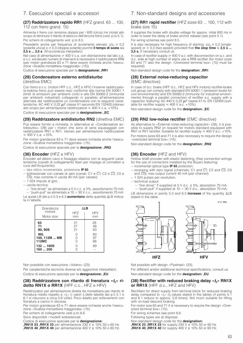
63
7. Esecuzioni speciali e accessori 7. Non-standard designs and accessories
(27) Raddrizzatore rapido RR1 (HFZ grand. 63 ... 100,112 con freno grand. 15)Alimenta il freno con tensione doppia per i 600 (circa) ms iniziali alloscopo di diminuire il ritardo di sblocco dell’àncora freno (ved. p.to 5.1).Per schemi di collegamento ved. p.to 8.5.Prevederlo anche per frequenza di avviamento elevata: z/z0 0,2(polarità unica) o 0,3 (doppia polarità) purché il tempo di sosta sia2,5 s ... 3,5 s. All’occorrenza interpellarci.Nel caso di alimentazione 400 V c.a. con disinserzione dal lato c.a.e c.c. ed elevato numero di interventi è necessario il raddrizzatore RR8(per motori grandezza 63 e 71 deve essere richiesta anche l’esecu-zione «Scatola morsettiera maggiorata» (15)).Codice di esecuzione speciale per la designazione: ,RR1
(28) Condensatore esterno antidisturbo(direttiva EMC)Con freno a c.c. (motori HFF c.c., HFZ e HFV) l’insieme raddrizzato-re-bobina freno può essere reso conforme alla norma EN 50081-1(limiti di emissioni per ambienti civili) e alla EN 50082-2 (immunitàper ambienti industriali) collegando in parallelo all’alimentazionealternata del raddrizzatore un condensatore con le seguenti carat-teristiche: AC 440 V, 0,22 F classe X1 secondo EN 132400 (idoneoallo scopo per alimentazione raddrizzatore 400 V c.a. +10%).Codice di esecuzione speciale per la designazione: ,EC
(29) Raddrizzatore antidisturbo RN2 (direttiva EMC)Può essere fornito a richiesta, in alternativa al «Condensatore an-tidisturbo» (28) per i motori che sono di serie equipaggiati conraddrizzatore RN1 o RV1. Idoneo per alimentazione raddrizzatore 400 V c.a. +10%.Per motori grandezze 63 e 71 deve essere richiesta anche l’esecu-zione «Scatola morsettiera maggiorata» (15).Codice di esecuzione speciale per la designazione: ,RN2
(36) Encoder (HFZ e HFV)Encoder ad albero cavo e fissaggio elastico con le seguenti carat-teristiche (cavetti di collegamento liberi per impiego di connettori acura dell’Acquirente):– tipo ottico incrementale, protezione IP 65;– bidirezionale con canale di zero (canali: C1 e C1—, C2 e C2—, C0 e
C0—); max corrente in uscita 40 mA (per canale);– 1 024 impulsi al giro;– uscita tecnica:
– “line driver” se alimentato a 5 V c.c. ± 5%, assorbimento 70 mA;– “push-pull” se alimentato a 10 30 V c.c., assorbimento 70 mA.
Le quote LB dei p.ti 5.3 e 6.3 aumentano della quantità LB indica-ta in tabella.
(27) RR1 rapid rectifier (HFZ sizes 63 ... 100, 112 withbrake size 15)It supplies the brake with double voltage for approx. initial 600 ms inorder to lower the delay of brake anchor release (see point 5.1).For wiring schemes see point 8.5.It is also necessary for high frequency of starting: z/z0 0,2 (single-speed) or 0,3 (two-speed) provided that the stop time is 2,5 s ...3,5 s. If necessary consult us.In case of rectifier supply 400 V a.c. with disconnection on a.c. andd.c. side at high number of starts use a RR8 rectifier (for motor sizes63 and 71 also the design «Oversized terminal box» (15) must berequired).Non-standard design code for the designation: ,RR1
(28) External noise-reducing capacitor(EMC directive)In case of d.c. brake (HFF d.c., HFZ and HFV motors) rectifier-brakecoil group can comply with standard EN 50081-1 (emission levels forcivil einvironments) and EN 50082-2 (immunity for industrial environ-ments) through a parallel connection of rectifier a.c. supply with acapacitor, featuring: AC 440 V, 0,22 F classe X1 to EN 132400 (suit-able for rectifier supply 400 V a.c. +10%).Non-standard design code for the designation: ,EC
(29) RN2 low-noise rectifier (EMC directive)As alternative to «External noise-reducing capacitor» (28), it is pos-sible to supply RN2 on request for motors standard equipped withRN1 or RV1 rectifier. Suitable for rectifier supply 400 V a.c. +10%.For motors sizes 63 and 71 it is also necessary to require the design«oversized terminal box» (15).Non-standard design code for the designation: ,RN2
(36) Encoder (HFZ and HFV)Hollow shaft encoder with elastic fastening, (free connection wiringsfor the use of connectors installed by the Buyer) featuring:– incremental optical type IP 65 protection;– reversing with zero signal (channels: C1 and C1—, C2 and C2—, C0
and C0—); max output current 40 mA (per channel);– 1 024 pulses per revolution;– technical output:
– “line driver” if supplied at 5 V d.c. ± 5%, absorption 70 mA;– “push-pull” if supplied at 10 30 V d.c., absorption 70 mA.
LB dimensions in points 5.3 and 6.3 increase of the quantity LBstated in the table.
Grandezza LBmotore HFZ HFV
Motor size mm mm
63 31 28)
71 27 4880, 90S 21 6390L 0 80
100, 112M ... MB 0 97112MC 0 66132 ... 160S 0 89160 ... 200 0 –
Non possibile con esecuzione «Volano» (23).Per caratteristiche tecniche diverse e/o aggiuntive interpellarci.Codice di esecuzione speciale per la designazione: ,EU
(38) Raddrizzatore con ritardo di frenatura «t2» ri-dotto RN1X o RR1X (HFF c.c., HFZ e HFV)Raddrizzatori per alimentazione diretta da morsettiera per ritardo difrenatura ridotto rispetto a «t2» (i valori t2 delle tabelle dei p.ti 5.1 e6.1 si riducono a circa 0,8 volte). Poco adatto per sollevamenti confrenature a carico in discesa.Per motori grandezze 63 e 71 deve essere richiesta anche l’esecu-zione «Scatola morsettiera maggiorata» (15).Per schemi di collegamento vedi p.to 8.6.Sono disponibili i modelli sottoelencati.Codice di esecuzione speciale per la designazione:,RN1X 23 ,RR1X 23 per alimentazione 230 V ± 10% 50 o 60 Hz,RN1X 40 ,RR1X 40 per alimentazione 400 V ± 10% 50 o 60 Hz.
Not possible with design «Flywheel» (23).For different and/or additional technical specifications, consult us.Non-standard design code for the designation: ,EU
(38) Rectifier with reduced braking delay «t2» RN1Xor RR1X (HFF d.c., HFZ and HFV)Rectifiers for direct supply from terminal block for reduced brakingdelay compared to «t2» (t2 values stated in the tables of points 5.1and 6.1 reduce to approx. 0,8 times). Not much suitable for liftingwith on-load descent braking.For motor size 63 and 71 it is necessary to require the design «Over-sized terminal box» (15).For wiring schemes see point 8.6.Following types are at disposal.Non-standard design code for the designation:,RN1X 23 ,RR1X 23 for supply 230 V ± 10% 50 or 60 Hz,RN1X 40 ,RR1X 40 for supply 400 V ± 10% 50 or 60 Hz.
HFZ HFV
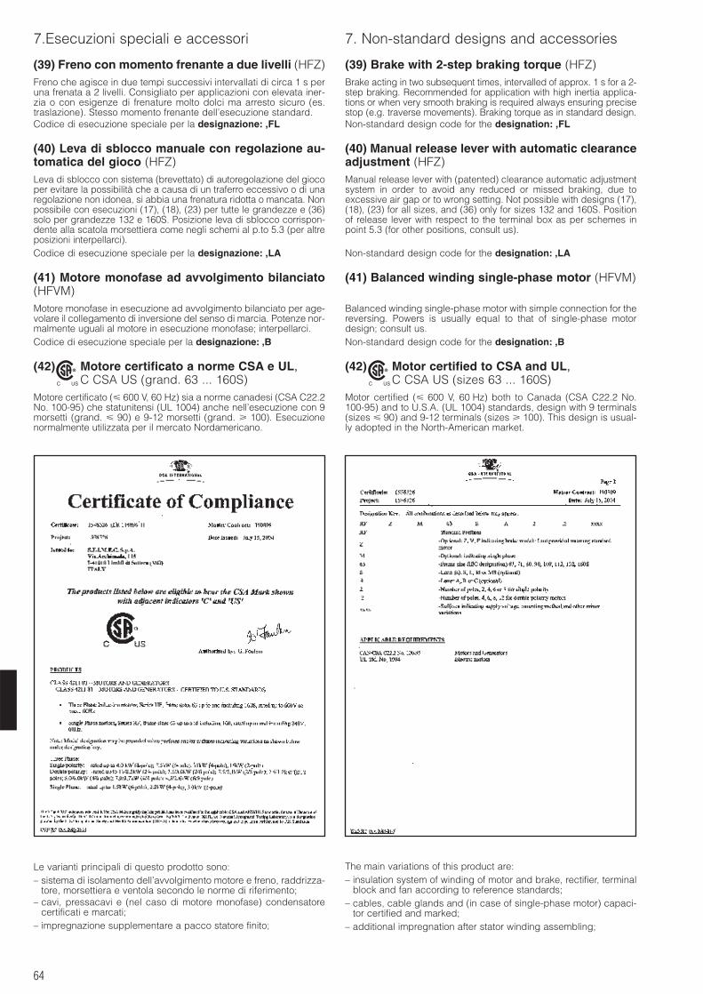
64
7.Esecuzioni speciali e accessori 7. Non-standard designs and accessories
(39) Freno con momento frenante a due livelli (HFZ)Freno che agisce in due tempi successivi intervallati di circa 1 s peruna frenata a 2 livelli. Consigliato per applicazioni con elevata iner-zia o con esigenze di frenature molto dolci ma arresto sicuro (es.traslazione). Stesso momento frenante dell’esecuzione standard.Codice di esecuzione speciale per la designazione: ,FL
(40) Leva di sblocco manuale con regolazione au-tomatica del gioco (HFZ)Leva di sblocco con sistema (brevettato) di autoregolazione del giocoper evitare la possibilità che a causa di un traferro eccessivo o di unaregolazione non idonea, si abbia una frenatura ridotta o mancata. Nonpossibile con esecuzioni (17), (18), (23) per tutte le grandezze e (36)solo per grandezze 132 e 160S. Posizione leva di sblocco corrispon-dente alla scatola morsettiera come negli schemi al p.to 5.3 (per altreposizioni interpellarci).Codice di esecuzione speciale per la designazione: ,LA
(41) Motore monofase ad avvolgimento bilanciato(HFVM)Motore monofase in esecuzione ad avvolgimento bilanciato per age-volare il collegamento di inversione del senso di marcia. Potenze nor-malmente uguali al motore in esecuzione monofase; interpellarci.Codice di esecuzione speciale per la designazione: ,B
(42) Motore certificato a norme CSA e UL,C CSA US (grand. 63 ... 160S)
Motore certificato ( 600 V, 60 Hz) sia a norme canadesi (CSA C22.2No. 100-95) che statunitensi (UL 1004) anche nell’esecuzione con 9morsetti (grand. 90) e 9-12 morsetti (grand. 100). Esecuzionenormalmente utilizzata per il mercato Nordamericano.
C US
®
(39) Brake with 2-step braking torque (HFZ)Brake acting in two subsequent times, intervalled of approx. 1 s for a 2-step braking. Recommended for application with high inertia applica-tions or when very smooth braking is required always ensuring precisestop (e.g. traverse movements). Braking torque as in standard design.Non-standard design code for the designation: ,FL
(40) Manual release lever with automatic clearanceadjustment (HFZ)Manual release lever with (patented) clearance automatic adjustmentsystem in order to avoid any reduced or missed braking, due toexcessive air gap or to wrong setting. Not possible with designs (17),(18), (23) for all sizes, and (36) only for sizes 132 and 160S. Positionof release lever with respect to the terminal box as per schemes inpoint 5.3 (for other positions, consult us).
Non-standard design code for the designation: ,LA
(41) Balanced winding single-phase motor (HFVM)
Balanced winding single-phase motor with simple connection for thereversing. Powers is usually equal to that of single-phase motordesign; consult us.Non-standard design code for the designation: ,B
(42) Motor certified to CSA and UL,C CSA US (sizes 63 ... 160S)
Motor certified ( 600 V, 60 Hz) both to Canada (CSA C22.2 No.100-95) and to U.S.A. (UL 1004) standards, design with 9 terminals(sizes 90) and 9-12 terminals (sizes 100). This design is usual-ly adopted in the North-American market.
C US
®
Le varianti principali di questo prodotto sono:– sistema di isolamento dell’avvolgimento motore e freno, raddrizza-
tore, morsettiera e ventola secondo le norme di riferimento;– cavi, pressacavi e (nel caso di motore monofase) condensatore
certificati e marcati;– impregnazione supplementare a pacco statore finito;
The main variations of this product are:– insulation system of winding of motor and brake, rectifier, terminal
block and fan according to reference standards;– cables, cable glands and (in case of single-phase motor) capaci-
tor certified and marked;– additional impregnation after stator winding assembling;
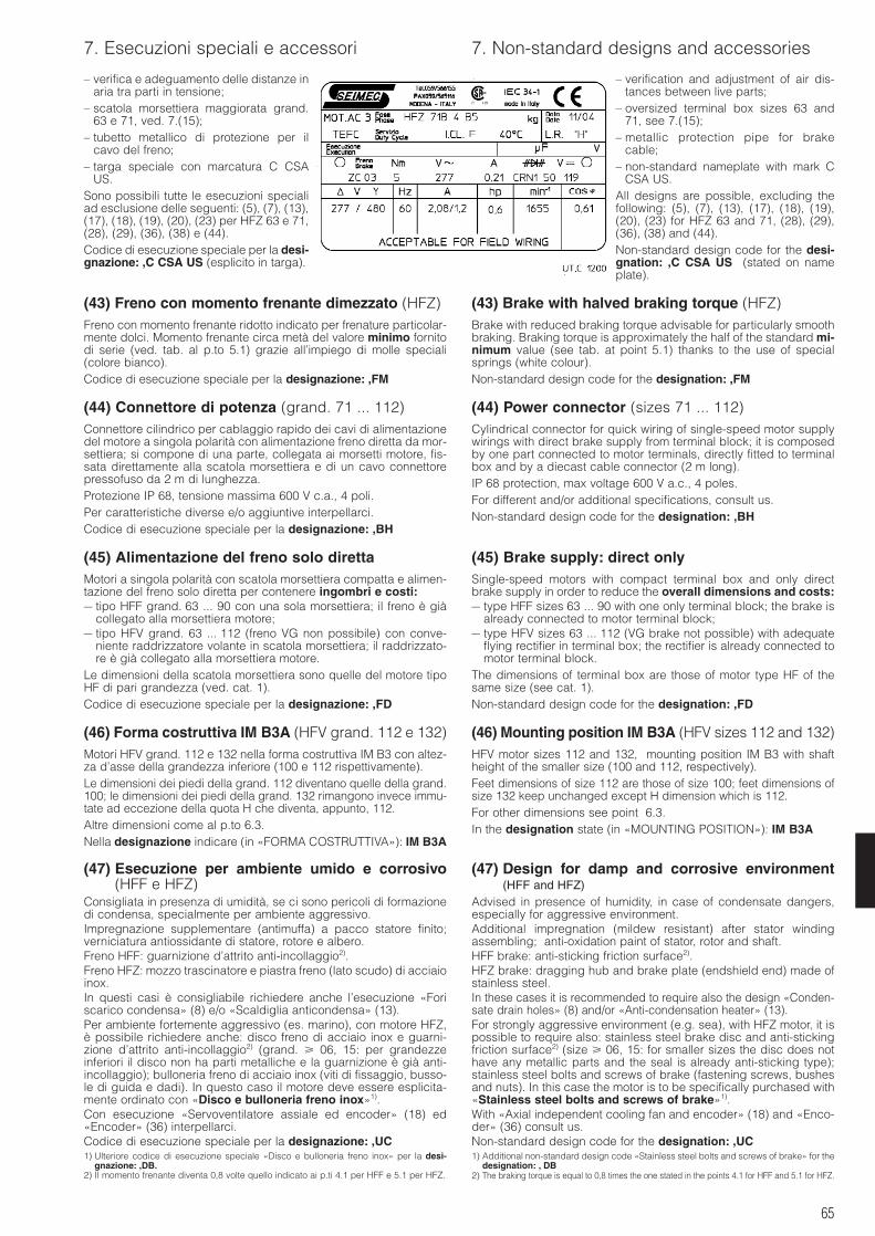
65
7. Esecuzioni speciali e accessori 7. Non-standard designs and accessories
– verifica e adeguamento delle distanze inaria tra parti in tensione;
– scatola morsettiera maggiorata grand.63 e 71, ved. 7.(15);
– tubetto metallico di protezione per ilcavo del freno;
– targa speciale con marcatura C CSAUS.
Sono possibili tutte le esecuzioni specialiad esclusione delle seguenti: (5), (7), (13),(17), (18), (19), (20), (23) per HFZ 63 e 71,(28), (29), (36), (38) e (44).Codice di esecuzione speciale per la desi-gnazione: ,C CSA US (esplicito in targa).
(43) Freno con momento frenante dimezzato (HFZ)Freno con momento frenante ridotto indicato per frenature particolar-mente dolci. Momento frenante circa metà del valore minimo fornitodi serie (ved. tab. al p.to 5.1) grazie all’impiego di molle speciali(colore bianco).Codice di esecuzione speciale per la designazione: ,FM
(44) Connettore di potenza (grand. 71 ... 112)Connettore cilindrico per cablaggio rapido dei cavi di alimentazionedel motore a singola polarità con alimentazione freno diretta da mor-settiera; si compone di una parte, collegata ai morsetti motore, fis-sata direttamente alla scatola morsettiera e di un cavo connettorepressofuso da 2 m di lunghezza.Protezione IP 68, tensione massima 600 V c.a., 4 poli.Per caratteristiche diverse e/o aggiuntive interpellarci.Codice di esecuzione speciale per la designazione: ,BH
(45) Alimentazione del freno solo direttaMotori a singola polarità con scatola morsettiera compatta e alimen-tazione del freno solo diretta per contenere ingombri e costi:– tipo HFF grand. 63 ... 90 con una sola morsettiera; il freno è già
collegato alla morsettiera motore;– tipo HFV grand. 63 ... 112 (freno VG non possibile) con conve-
niente raddrizzatore volante in scatola morsettiera; il raddrizzato-re è già collegato alla morsettiera motore.
Le dimensioni della scatola morsettiera sono quelle del motore tipoHF di pari grandezza (ved. cat. 1).Codice di esecuzione speciale per la designazione: ,FD
(46) Forma costruttiva IM B3A (HFV grand. 112 e 132)Motori HFV grand. 112 e 132 nella forma costruttiva IM B3 con altez-za d’asse della grandezza inferiore (100 e 112 rispettivamente).Le dimensioni dei piedi della grand. 112 diventano quelle della grand.100; le dimensioni dei piedi della grand. 132 rimangono invece immu-tate ad eccezione della quota H che diventa, appunto, 112.Altre dimensioni come al p.to 6.3.Nella designazione indicare (in «FORMA COSTRUTTIVA»): IM B3A
(47) Esecuzione per ambiente umido e corrosivo(HFF e HFZ)
Consigliata in presenza di umidità, se ci sono pericoli di formazionedi condensa, specialmente per ambiente aggressivo.Impregnazione supplementare (antimuffa) a pacco statore finito;verniciatura antiossidante di statore, rotore e albero.Freno HFF: guarnizione d’attrito anti-incollaggio2).Freno HFZ: mozzo trascinatore e piastra freno (lato scudo) di acciaioinox.In questi casi è consigliabile richiedere anche l’esecuzione «Foriscarico condensa» (8) e/o «Scaldiglia anticondensa» (13).Per ambiente fortemente aggressivo (es. marino), con motore HFZ,è possibile richiedere anche: disco freno di acciaio inox e guarni-zione d’attrito anti-incollaggio2) (grand. 06, 15: per grandezzeinferiori il disco non ha parti metalliche e la guarnizione è già anti-incollaggio); bulloneria freno di acciaio inox (viti di fissaggio, busso-le di guida e dadi). In questo caso il motore deve essere esplicita-mente ordinato con «Disco e bulloneria freno inox»1).Con esecuzione «Servoventilatore assiale ed encoder» (18) ed«Encoder» (36) interpellarci.Codice di esecuzione speciale per la designazione: ,UC1) Ulteriore codice di esecuzione speciale «Disco e bulloneria freno inox» per la desi-
gnazione: ,DB.2) Il momento frenante diventa 0,8 volte quello indicato ai p.ti 4.1 per HFF e 5.1 per HFZ.
– verification and adjustment of air dis-tances between live parts;
– oversized terminal box sizes 63 and71, see 7.(15);
– metallic protection pipe for brakecable;
– non-standard nameplate with mark CCSA US.
All designs are possible, excluding thefollowing: (5), (7), (13), (17), (18), (19),(20), (23) for HFZ 63 and 71, (28), (29),(36), (38) and (44).Non-standard design code for the desi-gnation: ,C CSA US (stated on nameplate).
(43) Brake with halved braking torque (HFZ)Brake with reduced braking torque advisable for particularly smoothbraking. Braking torque is approximately the half of the standard mi-nimum value (see tab. at point 5.1) thanks to the use of specialsprings (white colour).Non-standard design code for the designation: ,FM
(44) Power connector (sizes 71 ... 112)Cylindrical connector for quick wiring of single-speed motor supplywirings with direct brake supply from terminal block; it is composedby one part connected to motor terminals, directly fitted to terminalbox and by a diecast cable connector (2 m long).IP 68 protection, max voltage 600 V a.c., 4 poles.For different and/or additional specifications, consult us.Non-standard design code for the designation: ,BH
(45) Brake supply: direct onlySingle-speed motors with compact terminal box and only directbrake supply in order to reduce the overall dimensions and costs:– type HFF sizes 63 ... 90 with one only terminal block; the brake is
already connected to motor terminal block;– type HFV sizes 63 ... 112 (VG brake not possible) with adequate
flying rectifier in terminal box; the rectifier is already connected tomotor terminal block.
The dimensions of terminal box are those of motor type HF of thesame size (see cat. 1).Non-standard design code for the designation: ,FD
(46) Mounting position IM B3A (HFV sizes 112 and 132)HFV motor sizes 112 and 132, mounting position IM B3 with shaftheight of the smaller size (100 and 112, respectively).Feet dimensions of size 112 are those of size 100; feet dimensions ofsize 132 keep unchanged except H dimension which is 112.For other dimensions see point 6.3.In the designation state (in «MOUNTING POSITION»): IM B3A
(47) Design for damp and corrosive environment(HFF and HFZ)
Advised in presence of humidity, in case of condensate dangers,especially for aggressive environment.Additional impregnation (mildew resistant) after stator windingassembling; anti-oxidation paint of stator, rotor and shaft.HFF brake: anti-sticking friction surface2).HFZ brake: dragging hub and brake plate (endshield end) made ofstainless steel.In these cases it is recommended to require also the design «Conden-sate drain holes» (8) and/or «Anti-condensation heater» (13).For strongly aggressive environment (e.g. sea), with HFZ motor, it ispossible to require also: stainless steel brake disc and anti-stickingfriction surface2) (size 06, 15: for smaller sizes the disc does nothave any metallic parts and the seal is already anti-sticking type);stainless steel bolts and screws of brake (fastening screws, bushesand nuts). In this case the motor is to be specifically purchased with«Stainless steel bolts and screws of brake»1).With «Axial independent cooling fan and encoder» (18) and «Enco-der» (36) consult us.Non-standard design code for the designation: ,UC1) Additional non-standard design code «Stainless steel bolts and screws of brake» for the
designation: , DB2) The braking torque is equal to 0,8 times the one stated in the points 4.1 for HFF and 5.1 for HFZ.
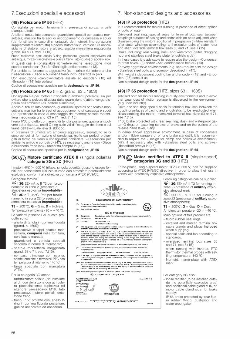
66
7.Esecuzioni speciali e accessori 7. Non-standard designs and accessories
(48) Protezione IP 56 (HFZ)Consigliata per motori funzionanti in presenza di spruzzi o gettid’acqua diretti.Anello di tenuta lato comando; guarnizioni speciali per scatola mor-settiera; mastice tra le sedi di accoppiamento di carcassa e scudi(da ripristinare in caso di smontaggio del motore); impregnazionesupplementare (antimuffa) a pacco statore finito; verniciatura antios-sidante di statore, rotore e albero; scatola morsettiera maggioratagrand. 63 e 71, ved. 7.(15).Freno realizzato con: anello V-ring posteriore, guaina antipolvere edantiacqua, mozzo trascinatore e piastra freno (lato scudo) di acciaio inox.In questi casi è consigliabile richiedere anche l’esecuzione «Foriscarico condensa» (8) e/o «Scaldiglia anticondensa» (13).Per ambiente fortemente aggressivo (es. marino) richiedere anchel’ esecuzione «Disco e bulloneria freno inox» descritta in (47).Con esecuzione «Servoventilatore assiale ed encoder» (18) ed«Encoder» (36) interpellarci.Codice di esecuzione speciale per la designazione: ,IP 56.
(49) Protezione IP 65 (HFZ, grand. 63…160S)Consigliata sia per motori funzionanti in ambienti polverosi, sia perevitare che la polvere di usura della guarnizione d’attrito venga dis-persa nell’ambiente (es. settore alimentare).Anello di tenuta lato comando; guarnizioni speciali per scatola mor-settiera; mastice tra le sedi di accoppiamento di carcassa e scudi(da ripristinare in caso di smontaggio del motore); scatola morset-tiera maggiorata grand. 63 e 71, ved. 7.(15).Freno IP65 protetto con: anello di tenuta posteriore, guaina antipol-vere ed antiacqua, anelli O-ring sulle viti di fissaggio del freno e suitiranti dell’eventuale leva di sblocco.In presenza di umidità e/o ambiente aggressivo, soprattutto se cisono pericoli di formazione di condensa, muffe e/o periodi prolun-gati di fermo del freno è consigliabile richiedere l’«Esecuzione perambiente umido e corrosivo» (47), se necessario anche con «Discoe bulloneria freno inox» (descritta sempre in (47)).Codice di esecuzione speciale per la designazione: ,IP 65
(50) Motore certificato ATEX ll (singola polarità)categorie 3G e 3D (HFZ)
I motori HFZ ( 600 V) trifase, singola polarità, possono essere for-niti, per consentirne l’utilizzo in zone con atmosfere potenzialmenteesplosive, conformi alla direttiva comunitaria ATEX 94/9/CE.Categorie fornibili:
Il 3G EEx nA ,c II T3 per funzio-namento in zona 2 (presenza diatmosfera esplosiva improbabile);
Il 3D c T135°C IP55 per funzio-namento in zona 22 (presenza diatmosfera esplosiva improbabile);T3 = 200 °C; G = Gas; D = Polvere.Temperatura ambiente -20 ÷ +40 °C.Le varianti principali di questo pro-dotto sono:– anello di tenuta in gomma fluorata
(grand. 160S);– pressacavo e tappi scatola mor-
settiera, compresi nella fornitura,certificati e marcati;
– guarnizioni e ventola specialisecondo le norme di riferimento;
– scatola morsettiera maggioratagrand. 63 e 71, ved. 7.(15);
– nel caso d’impiego con inverter,sonde termiche a termistori PTC contemperatura di intervento 140 °C;
– targa speciale con marcaturaATEX.
Per la categoria 3G anche:– raddrizzatore sciolto (da installare
al di fuori della zona con atmosfe-ra potenzialmente esplosiva) edulteriore pressacavo M16, latopressacavo motore, per alimenta-zione freno;
– freno IP 55 protetto con: anello V-ring in gomma fluorata posteriore,guaina antipolvere ed antiacqua.
(48) IP 56 protection (HFZ)It is recommended for motors running in presence of direct splashor bolts of water. Drive-end seal ring; special seals for terminal box; seal betweencouplings surfaces of casing and endshields (to be re-adjusted whendisassembling the motor); additional impregnation (mildew resistant)after stator windings assembling; anti-oxidation paint of stator, rotorand shaft; overside terminal box sizes 63 and 71, see 7.(15).Brake including: rear V-ring, dust- and waterproof gaiter, dragginghub and stainless steel brake plate (endshield side).In these cases it is advisable to require also the design «Condensa-te drain holes» (8) and/or «Anti-condensation heater» (13).For very aggressive environments (e.g. sea) require also the design«Stainless steel bolts and screws» described in (47).With «Axial independent cooling fan and encoder» (18) and «Enco-der» (36) consult us.Non-standard design code for the designation: ,IP 56
(49) IP 65 protection (HFZ, sizes 63 ... 160S)Advised both for motors running in dusty environments and to avoidthat wear dust of friction surface is dispersed in the environment(e.g. food industry).Drive-end seal ring; special seals for terminal box; seal between thecoupling surfaces of casing and endshields (to be re-adjusted whendisassembling the motor); oversized terminal box sizes 63 and 71,see 7.(15).IP 65 brake protected with: rear seal ring, dust- and waterproof gai-ter, O-rings on fastening screws of brake and on the pullers of therelease hand lever, if any.In damp and/or aggressive environment, in case of condensateand/or mildew dangers or of long brake standstill, it is recommen-ded to require the «Design for damp and corrosive environment»(47), if necessary also with «Stainless steel bolts and screws»(described always in (47)).Non-standard design code for the designation: ,IP 65
(50) Motor certified to ATEX ll (single-speed)categories 3G and 3D (HFZ)
Three-phase, single-speed motor HFZ ( 600 V) can be suppliedaccording to ATEX 94/9/EC directive, in order to allow their use inzones with potentially explosive atmospheres.
Following categories can be supplied:Il 3G EEx nA II T3 for running in
zone 2 (presence of unlikely explo-sive atmosphere);
Il 3D T135°C IP55 for running inzone 22 (presence of unlikely explo-sive atmosphere);T3 = 200°C; G = Gas; D = Dust.Ambient temperature -20 ÷ +40 °C.Main options of this product are:– fluoro rubber seal rings;– certified and marked terminal box
cable glands and plugs includedwhen supplyng;
– special seals and fan according tostandards;
– oversized terminal box sizes 63and 71, see 7.(15);
– when running with inverter, PTCthermistor thermal probes with set-ting temperature: 140 °C;
– Non-std. name-plate with ATEXmark.
For category 3G also:– loose rectifier (to be installed outsi-
de the potentially explosive area)and additional cable gland M16, onmotor cable gland side, for brakesupply;
– IP 55 brake protected by: rear fluo-ro rubber V-ring, dust-proof andwater-proof gaiter.
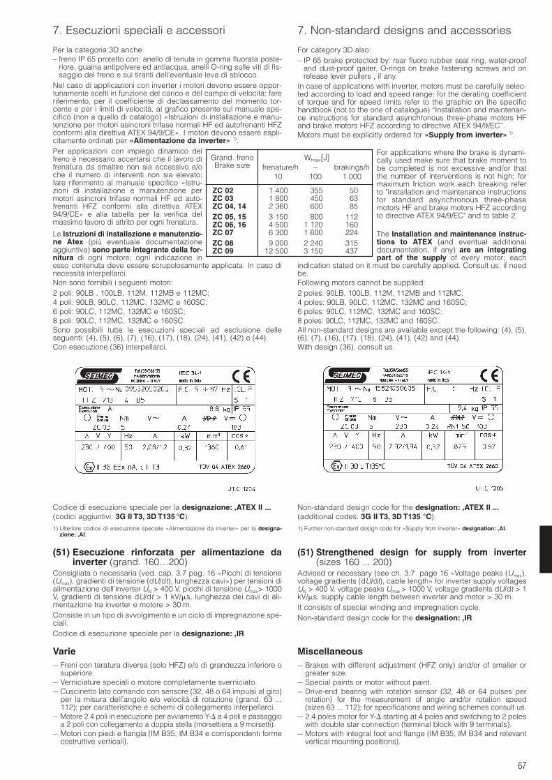
67
7. Esecuzioni speciali e accessori 7. Non-standard designs and accessories
Per la categoria 3D anche:– freno IP 65 protetto con: anello di tenuta in gomma fluorata poste-
riore, guaina antipolvere ed antiacqua, anelli O-ring sulle viti di fis-saggio del freno e sui tiranti dell’eventuale leva di sblocco.
Nel caso di applicazioni con inverter i motori devono essere oppor-tunamente scelti in funzione del carico e del campo di velocità: fareriferimento, per il coefficiente di declassamento del momento tor-cente e per i limiti di velocità, al grafico presente sul manuale spe-cifico (non a quello di catalogo) «Istruzioni di installazione e manu-tenzione per motori asincroni trifase normali HF ed autofrenanti HFZconformi alla direttiva ATEX 94/9/CE». I motori devono essere espli-citamente ordinati per «Alimentazione da inverter» 1).Per applicazioni con impiego dinamico delfreno è necessario accertarsi che il lavoro difrenatura da smaltire non sia eccessivo e/oche il numero di interventi non sia elevato;fare riferimento al manuale specifico «Istru-zioni di installazione e manutenzione permotori asincroni trifase normali HF ed auto-frenanti HFZ conformi alla direttiva ATEX94/9/CE» e alla tabella per la verifica delmassimo lavoro di attrito per ogni frenatura.
Le Istruzioni di installazione e manutenzio-ne Atex (più eventuale documentazioneaggiuntiva) sono parte integrante della for-nitura di ogni motore; ogni indicazione inesso contenuta deve essere scrupolosamente applicata. In caso dinecessità interpellarci.Non sono fornibili i seguenti motori:2 poli: 90LB , 100LB, 112M, 112MB e 112MC;4 poli: 90LB, 90LC, 112MC, 132MC e 160SC;6 poli: 90LC, 112MC, 132MC e 160SC;8 poli: 90LC, 112MC, 132MC e 160SC.Sono possibili tutte le esecuzioni speciali ad esclusione delleseguenti: (4), (5), (6), (7), (16), (17), (18), (24), (41), (42) e (44).Con esecuzione (36) interpellarci.
Codice di esecuzione speciale per la designazione: ,ATEX ll ...(codici aggiuntivi: 3G II T3, 3D T135 °C).
1) Ulteriore codice di esecuzione speciale «Alimentazione da inverter» per la designa-zione: ,AI.
(51) Esecuzione rinforzata per alimentazione dainverter (grand. 160…200)
Consigliata o necessaria (ved. cap. 3.7 pag. 16 «Picchi di tensione(Umax), gradienti di tensione (dU/dt), lunghezza cavi») per tensioni dialimentazione dell’inverter UN > 400 V, picchi di tensione Umax> 1000V, gradienti di tensione dU/dt > 1 kV/s, lunghezza dei cavi di ali-mentazione tra inverter e motore > 30 m.Consiste in un tipo di avvolgimento e un ciclo di impregnazione spe-ciali.Codice di esecuzione speciale per la designazione: ,IR
Varie– Freni con taratura diversa (solo HFZ) e/o di grandezza inferiore o
superiore.– Verniciature speciali o motore completamente sverniciato.– Cuscinetto lato comando con sensore (32, 48 o 64 impulsi al giro)
per la misura dell’angolo e/o velocità di rotazione (grand. 63 ...112); per caratteristiche e schemi di collegamento interpellarci.
– Motore 2.4 poli in esecuzione per avviamento Y- a 4 poli e passaggioa 2 poli con collegamento a doppia stella (morsettiera a 9 morsetti).
– Motori con piedi e flangia (IM B35, IM B34 e corrispondenti formecostruttive verticali).
For category 3D also:– IP 65 brake protected by: rear fluoro rubber seal ring, water-proof
and dust-proof gaiter, O-rings on brake fastening screws and onrelease lever pullers , if any.
In case of applications with inverter, motors must be carefully selec-ted according to load and speed range: for the derating coefficientof torque and for speed limits refer to the graphic on the specifichandbook (not to the one of catalogue) “Installation and maintenan-ce instructions for standard asynchronous three-phase motors HFand brake motors HFZ according to directive ATEX 94/9/EC”.Motors must be explicitly ordered for «Supply from inverter» 1).
For applications where the brake is dynami-cally used make sure that brake moment tobe completed is not excessive and/or thatthe number of interventions is not high; formaximum friction work each breaking referto "Installation and maintenance instructionsfor standard asynchronous three-phasemotors HF and brake motors HFZ accordingto directive ATEX 94/9/EC" and to table 2.
The Installation and maintenance instruc-tions to ATEX (and eventual additionaldocumentation, if any) are an integratingpart of the supply of every motor; each
indication stated on it must be carefully applied. Consult us, if needbe.Following motors cannot be supplied:2 poles: 90LB, 100LB, 112M, 112MB and 112MC;4 poles: 90LB, 90LC, 112MC, 132MC and 160SC;6 poles: 90LC, 112MC, 132MC and 160SC;8 poles: 90LC, 112MC, 132MC and 160SC.All non-standard designs are available except the following: (4), (5),(6), (7), (16), (17), (18), (24), (41), (42) and (44).With design (36), consult us.
Non-standard design code for the designation: ,ATEX ll ...(additional codes: 3G II T3, 3D T135 °C).
1) Further non-standard design code for «Supply from inverter» designation: ,AI.
(51) Strengthened design for supply from inverter(sizes 160 ... 200)
Advised or necessary (see ch. 3.7 page 16 «Voltage peaks (Umax),voltage gradients (dU/dt), cable length» for inverter supply voltagesUN > 400 V, voltage peaks Umax > 1000 V, voltage gradients dU/dt > 1kV/s, supply cable length between inverter and motor > 30 m.It consists of special winding and impregnation cycle.Non-standard design code for the designation: ,IR
Miscellaneous– Brakes with different adjustment (HFZ only) and/or of smaller or
greater size.– Special paints or motor without paint.– Drive-end bearing with rotation sensor (32, 48 or 64 pulses per
rotation) for the measurement of angle and/or rotation speed (sizes 63 ... 112); for specifications and wiring schemes consult us.
– 2.4 poles motor for Y- starting at 4 poles and switching to 2 poleswith double star connection (terminal block with 9 terminals).
– Motors with integral foot and flange (IM B35, IM B34 and relevantvertical mounting positions).
Grand. freno Wfmax[J]Brake size frenature/h – brakings/h
10 100 1 000
ZC 02 1 400 355 50ZC 03 1 800 450 63ZC 04, 14 2 360 600 85ZC 05, 15 3 150 800 112ZC 06, 16 4 500 1 120 160ZC 07 6 300 1 600 224ZC 08 9 000 2 240 315ZC 09 12 500 3 150 437

68
7.Esecuzioni speciali e accessori 7. Non-standard designs and accessories
– Motore senza ventilazione (escluso HFV); per prestazioni interpel-larci.
– Esecuzione per alte temperature.– Encoder per alte temperature (fino a 90 °C)– Anello di tenuta lato comando (per tenuta olio) per forme costrut-
tive con flangia; cuscinetti 2RS.– Freno con micro interruttore per segnalare l’usura o la condizione
di blocco/sblocco del freno.– Motori elettricamente conformi alle norme NEMA MG1 Design B
(per altri Designs interpellarci).– Sensore temperatura PT 100– Asta speciale della leva di sblocco per mantenimento del freno in
condizioni di sblocco.
– Motor without fan-cooling (HFV excluded); for performances con-sult us.
– High temperatures design.– Encoder for high temperature (up to 90 °C)– Drive end seal ring (for oil seal) for mounting positions with flange;
2RS type bearings.– Brake with microswitch in order to indicate brake wear or brake
jam/release.– Electrical features of the motors to NEMA MG1 B Design (for other
Designs consult us).– Temperature probe PT 100– Special release lever rod to keep brake release condition.
69
8. Installazione e manutenzione 8. Installation and maintenance
8.1 Avvertenze generali sulla sicurezzaPericolo: le macchine elettriche rotanti presentano parti perico-lose in quanto poste sotto tensione, in movimento, con tempe-rature superiori a 50 °C.Il motore non deve essere messo in servizio prima di essereincorporato su una macchina che risulti conforme alla direttiva98/37/CEE.Un’installazione non corretta, un uso improprio, la rimozione delleprotezioni, lo scollegamento dei dispositivi di protezione, la carenzadi ispezioni e manutenzione, i collegamenti impropri, possono cau-sare danni gravi a persone e cose.Pertanto, il motore deve essere movimentato, installato, messo in ser-vizio, gestito, ispezionato, manutenuto e riparato esclusivamente dapersonale responsabile qualificato (definizione secondo IEC 364).Nel corso di ogni operazione elencata, seguire le istruzioni riportatenel presente catalogo, le istruzioni e avvertenze che accompagnanoogni motore, le vigenti disposizioni legislative di sicurezza e tutte lenormative applicabili in materia di corretta installazione elettrica.Poiché le macchine elettriche del presente catalogo sono normal-mente destinate ad essere impiegate in aree industriali, protezionisupplementari eventualmente necessarie devono essere adottatee garantite da chi è responsabile dell’installazione.I lavori sulla macchina elettrica debbono avvenire a macchina fermae scollegata dalla rete (compresi gli equipaggiamenti ausiliari). Sesono presenti protezioni elettriche eliminare ogni possibilità di riav-viamento improvviso attenendosi alle specifiche raccomandazionisull’impiego delle varie apparecchiature. In motori monofase il con-densatore di esercizio può rimanere caricato tenendo temporanea-mente in tensione i relativi morsetti anche a motore fermo.Prima della messa in servizio verificare il corretto funzionamento delfreno e l’adeguatezza del momento frenante avendo cura di evi-tare pericoli per persone e cose.Direttiva EMC. I motori asincroni trifase e monofase alimentati darete e funzionanti in servizio continuo sono conformi alle norme EN50081 e EN 50082. Non sono necessari particolari accorgimenti dischermatura. La stessa cosa vale per il motore dell’eventuale ser-voventilatore.Nel caso di funzionamento intermittente, le eventuali perturbazionigenerate dai dispositivi di inserzione devono essere limitate me-diante adeguati cablaggi (indicati dal produttore dei dispositivi).Con freno a c.c. (motori HFF c.c., HFZ e HFV) l’insieme raddrizzatore-bobina freno può essere reso conforme alla norma EN 50081-1 (limitidi emissioni per ambienti civili) e alla EN 50082-2 (immunità perambienti industriali) equipaggiando con il raddrizzatore RN2 (ved.cap. 7.(29)) i motori di serie dotati di raddrizzatore RN1 e RV1 o colle-gando in parallelo all’alimentazione alternata del raddrizzatore un con-densatore con le seguenti caratteristiche: AC 440 V, 0,22 F classe X1secondo EN 132400 (ved. cap. 7.(28)). Entrambe le soluzioni sonoidonee per tensioni di alimentazione raddrizzatore 400 V c.a. +5%.Nel caso di motori alimentati da inverter devono essere seguite leistruzioni di cablaggio del produttore dell’inverter.Nel caso di alimentazione separata del freno, i cavi di alimentazio-ne del freno stesso devono essere tenuti separati da quelli di poten-za. È possibile tenere insieme i cavi freno con altri cavi solo se sonoschermati.In caso di esecuzione con encoder attenersi alle seguenti indica-zioni: installare la scheda elettronica di controllo il più vicino possi-bile all’encoder (e il più lontano possibile dall’eventuale inverter, onell’impossibilità di farlo, schermare in maniera efficace l’inverterstesso); utilizzare sempre cavi schermati e twistati con connessionea terra da entrambe le estremità; i cavi di segnale dell’encoderdevono giacere separatamente dai cavi di potenza (vedere anche leistruzioni specifiche allegate al motore).Tutti i suddetti componenti sono destinati ad essere incorporati inapparecchi o sistemi completi e non debbono essere messi inservizio fino a quando l’apparecchio o il sistema nel quale ilcomponente è stato incorporato non sia stato reso conformealla direttiva 89/336/CEE.Conformità alla Direttiva Europea «Bassa tensione» 73/23/CEE(modificata dalla direttiva 93/68): i motori sono conformi alla diretti-va e riportano per questo il marchio CE in targa.
8.2 Installazione: indicazioni generaliAl ricevimento, verificare che il motore corrisponda a quanto ordi-nato e che non abbia subito danni durante il trasporto. Non metterein servizio motori danneggiati.I golfari presenti sui motori servono al sollevamento del solo motoree non di altre macchine ad esso accoppiate.Per un’eventuale giacenza a magazzino l’ambiente deve esserepulito, asciutto, privo di vibrazioni (veff 0,2 mm/s) e agenti corrosi-vi. Proteggere sempre il motore dall’umidità.
8.1 General safety instructionsDanger: electric rotating machines present dangerous parts:when operating they have live and rotating components withtemperatures higher than 50 °C.Motor should not be put into service before it has been incor-porated on a machine which conforms to 98/37/EEC directive.An incorrect installation, an improper use, the removing of protec-tions, the disconnection of protection devices, the lack of inspec-tions and maintenance, the inadequate connections may causesevere personal injury or property damage.Therefore motor must be moved, installed, put into service, handled,controlled, serviced and repaired exclusively by responsibleskilled personnel (definition to IEC 364). During each mentionedoperation, follow the instructions of this catalogue, the instructionsand warnings relevant to each motor, all existing safety laws andstandards concerning correct electric installations.Since electric machines of this catalogue are usually installed in in-dustrial areas, additional protection measures, if necessary, mustbe adopted and assured by the person responsible for the installation.When working on electric machine, machine must be stopped anddisconnected from the power line (including auxiliary equipment). Ifthere are electric protections, avoid any possibility of unexpectedrestarting, paying attention to specific recommendations on equip-ment application. In single-phase motors, running capacitor canremain temporily charged keeping live the relevant terminals evenafter motor stop.Before putting into service verify the correct operation of the brakeand the adequacy of braking torque in order to avoid dangers forpersons and things.EMC directive. Asynchronous three-phase and single-phase motorssupplied from the line and running in continuous duty comply withstandards EN 50081 and EN 50082. No particular shieldings arenecessary. This is also valid for the motor of independent coolingfan, if any.In case of jogging operation, any disturbance generated by inser-tion devices must be limited through adequate wirings (as indicatedby device manufacturer).In case of d.c. brake (HFF d.c., HFZ and HFV motors) rectifier-brakecoil group can comply with standards EN 50081-1 (emission levels forcivil environments) and EN 50082-2 (immunity for industrial environ-ments) by arranging with RN2 rectifier (see ch. 7.(29)) the standardmotors equipped with RN1 and RV1 rectifier or by connecting in par-allel to the a.c. rectifier a capacitor, featuring: AC 440 V, 0,22 F classX1 to EN 132400 (see ch. 7.(28)). Both solutions are suitable for recti-fier supply voltage 400 V a.c. +5%.Where motors are supplied by inverters it is necessary to follow thewiring instructions of the manufacturer of the inverter.When brake is separately supplied, brake cables must be kept sep-arate from power cables. It is possible to keep together brakecables with other cables only if they are shielded.In case of design with encoder pay attention to following instructions:install the control electronic board as near as possible the encoder(and as far as possible from inverter, if any; if not possible, carefullyshield the inverter); always use twisted pairs shielded leads con-nected to earth on both ends; signal cables of the encoder must beseparate from the power cables (see specific instructions attached tothe motor).All above mentioned components are designed to be incorporatedinto equipment or complete systems and should not be put intoservice before equipment or system has been made in con-formity with 89/336/EEC directive.Compliance with «Low voltage» 73/23/EEC European Directive(modified by directive 93/68): motors meet the requirements of thisdirective and are therefore CE marked on name plate.
8.2 Installation: general directionsOn receipt, verify that motor corresponds to order and that it has notbeen damaged during the transport. Do not put into service anydamaged motors.Eyebolts on motors are suitable only for lifting the motor and no othermachines fitted to it.In case of storing the environment must be clean, dry, free fromvibrations (veff 0,2 mm/s) and corrosive agents. Always protectmotor from humidity.
70
8. Installazione e manutenzione 8. Installation and maintenance
Controllo della resistenza di isolamento. Prima della messa inservizio e dopo lunghi periodi di inattività o giacenza a magazzino,si dovrà misurare la resistenza d’isolamento tra gli avvolgimenti everso massa con apposito strumento in corrente continua (500 V).Non toccare i morsetti durante e negli istanti successivi alla mi-surazione in quanto i morsetti sono sotto tensione.La resistenza d’isolamento, misurata con l’avvolgimento a tempera-tura di 25 °C, non deve essere inferiore a 10 MΩ per avvolgimentonuovo, a 1 MΩ per avvolgimento di macchina che ha funzionato perdiverso tempo. Valori inferiori sono normalmente indice di presenzadi umidità negli avvolgimenti; provvedere in tal caso ad essiccarli.Nell’installazione sistemare il motore in modo che si abbia unampio passaggio d’aria (dal lato ventola) per il raffreddamento. Evi-tare che si abbiano: strozzature nei passaggi d’aria; fonti di calorenelle vicinanze tali da influenzare la temperatura sia dell’aria di raf-freddamento sia del motore (per irraggiamento); insufficiente ricir-colazione d’aria o in generale casi di applicazione che compromet-tano il regolare scambio termico.Nel caso si prevedano sovraccarichi di lunga durata o pericoli dibloccaggio, installare salvamotori, limitatori elettronici di momentotorcente o altri dispositivi similari.Per servizi con elevato numero di avviamenti a carico è consigliabilela protezione del motore con sonde termiche (incorporate nello stes-so): l’interruttore magnetotermico non è idoneo in quanto dovrebbeessere tarato a valori superiori alla corrente nominale del motore.Quando l’avviamento è a vuoto (o comunque a carico molto ridotto)ed è necessario avere avviamenti dolci, correnti di spunto basse, sol-lecitazioni contenute, adottare l’avviamento a tensione ridotta (es.:avviamento Y-, con autotrasformatore, con inverter, ecc.).Prima di effettuare l’allacciamento elettrico assicurarsi che l’alimen-tazione corrisponda ai dati di targa per motore, freno, eventuale ser-voventilatore, ecc.Scegliere cavi di sezione adeguata in modo da evitare surriscalda-menti e/o eccessive cadute di tensione ai morsetti del motore.Eseguire il collegamento secondo gli schemi indicati nel foglio con-tenuto nella scatola morsettiera riportati al p.to 8.3.
Le parti metalliche dei motori che normalmente non sono sottotensione devono essere stabilmente collegate a terra,mediante un cavo di sezione adeguata, utilizzando l’apposito
morsetto contrassegnato all’interno della scatola morsettiera.Per non alterare il grado di protezione dichiarato in targa, richiuderela scatola morsettiera posizionando correttamente la guarnizione eserrando tutte le viti di fissaggio. Per installazioni in ambienti con fre-quenti spruzzi d’acqua si consiglia di sigillare la scatola morsettierae l’entrata del bocchettone pressacavo con mastice per guarnizioni.Per motori trifase il senso di rotazione è orario (visto lato comando)se i collegamenti sono effettuati come al p.to 8.3. Se il senso di rota-zione non corrisponde a quello desiderato, invertire due fasi dellalinea di alimentazione; per motore monofase seguire le istruzioniindicate al p.to 8.3.In caso di inserzione o disinserzione di avvolgimenti motore conpolarità elevata ( 6 poli) si possono avere picchi di tensione dan-nosi. Predisporre idonee protezioni (es. varistori o filtri) sullalinea di alimentazione. Anche l’impiego di inverter richiede alcuneprecauzioni relative alla sua qualità, al valore della tensione di reteUN, ai picchi di tensione (Umax), ai gradienti di tensione (dU/dt) e allalunghezza dei cavi tra inverter e motore; potrebbero essere neces-sarie esecuzioni speciali del motore (da richiedere in fase d’ordine)e/o filtri adeguati da inserire sulla linea di alimentazione, ved. cap.3.7 pag. 16 «Picchi di tensione (Umax), gradienti di tensione (dU/dt),lunghezza cavi».Quando è possibile, proteggere il motore con opportuni accorgi-menti dall’irraggiamento solare e dalle intemperie: quest’ultima pro-tezione diventa necessaria quando il motore è installato ad asseverticale con ventola in alto.La superficie alla quale viene fissato il motore deve essere bendimensionata e livellata per garantire: stabilità di fissaggio, di alli-neamento del motore con la macchina utilizzatrice e assenza divibrazioni indotte sul motore stesso.Accoppiamenti. Per il foro degli organi calettati sull’estremità d’alberoè consigliata la tolleranza H7; per estremità d’albero con D = 55 mm,purché il carico sia uniforme e leggero, la tolleranza può essere G7.Prima di procedere al montaggio pulire bene e lubrificare le super-fici di contatto per evitare pericoli di grippaggio.Il montaggio e lo smontaggio si effettuano con l’ausilio di tiranti e diestrattori avendo cura di evitare urti e colpi che potrebbero dan-neggiare irrimediabilmente i cuscinetti.Nel caso di accoppiamento diretto o con giunto curare l’allineamen-to del motore rispetto all’asse della macchina accoppiata. Se neces-sario applicare un giunto elastico o flessibile.Nel caso di trasmissione a cinghia accertarsi che lo sbalzo sia mini-mo e che l’asse del motore sia sempre parallelo all’asse della mac-china. Le cinghie non devono essere eccessivamente tese per nonindurre carichi eccessivi sui cuscinetti e sull’albero motore.
Insulation resistance control. Before putting into service and afterlong stillstanding or storing periods it is necessary to measure insu-lation resistance between the windings and to earth by adequated.c. instrument (500 V). Do not touch the terminals during andjust after the measurement because of live terminals.Insulation resistance, measured at 25 °C winding temperature, mustnot be lower than 10 MΩ for new winding, than 1 MΩ for winding runfor a long time. Lower values usually denote the presence of humid-ity in the windings; in this case let them dry.During the installation, position the motor so as to allow a free pas-sage of air (on fan side) for cooling. Avoid: any obstruction to the air-flow; heat sources near the motor that might affect the temperaturesboth of cooling air and of motor (for radiation); insufficient air recy-cle or any other factor hindering the steady heat exchange.For full load and long lasting running of for jamming conditions,cutouts, electronic torque limiters or other similar devices should befitted.Where duty cycles involve a high number of on-load starts, it is advis-able to utilize thermal probes for motor protection (fitted on thewiring); magnetothermic breaker is unsuitable since its thresholdmust be set higher than the motor nominal current of rating.For no-load starts (or with very reduced load) and whenever it is nec-essary to have smooth starts, low starting currents and reducedstresses, adopt a reduced voltage starting (e.g.: Y- starting, withstarting auto-transformer, with inverter, etc.).Before wiring up to the electrical power supply make sure that thevoltage corresponds to name plate data for: motor, brake and inde-pendent cooling fan, if any, etc.Select cables of suitable section in order to avoid overheatingsand/or excessive voltage drops at motor terminals.Make sure that connection is according to schemes as per sheetcontained in the terminal box (see point 8.3).
Metallic parts of motors which are usually not under voltage,must be firmly connected to earth through a cable of ade-quate section and by using the proper terminal inside the ter-
minal box marked for the purpose.In order not to alter protection class shown on name plate, close theterminal box by correctly positioning the gasket and tightening allfastening screws. For installations in environments with frequentwater sprays, it is advisable to seal the terminal box and the cablegland.For three-phase motors the direction of rotation is clockwise (drive-end view) if connections are according to point 8.3. If direction ofrotation is not as desired, invert two phases at the terminals; for sin-gle-phase motor follow the instructions of point 8.3.In case of connection or disconnection of high polarity ( 6 poles)motor windings, there can be dangerous voltage peaks. Pre-arrangethe proper protection (e.g. varistors or filters) on the supply-line. Also the application of inverter requires some precautions rel-evant to its quality, to the value of mains voltage UN, to voltage peaks(Umax), to voltage gradients (dU/dt) and to cable length betweeninverter and motor; some non-standard motor designs necessary (tobe required when ordering) and/or adequate filters to be inserted onsupply line could be necessary; see ch. 3.7, page 16 «Voltagepeaks (Umax), voltage gradients (dU/dt), cable length».Motors should be protected whenever possible, and by whateverappropriate means, from solar radiation and extremes of weather;weather protection becomes essential when the motor is installedwith vertical shaft and fan upwards.The surface to which motor is fitted must be correctly dimensionedand flattened in order to allow fastening security and motor align-ment with driven machine and to avoid vibrations on the motor.Pairings. It is recommended to machine the hole of parts keyed ontoshaft ends to H7 tolerance; for shaft ends having D = 55 mm, toleranceG7 is permissible provided that the load is uniform and light.Before mounting, clean mating surfaces throughly and lubricateagainst seizure.Assemble and disassemble with the aid of jacking screws andpullers taking care to avoid impacts and shocks which may irre-mediably damage bearings.In case of direct fitting or coupling be sure that the motor has beencarefully aligned with the driven machine. If necessary, interpose aflexible or elastic coupling.In case of V-belt drives make sure that overhung is minimum and thatdriven shaft is always parallel to machine shaft. V-belts should not beexcessively tensioned in order to avoid excessive loads on bearingsand motor shaft.
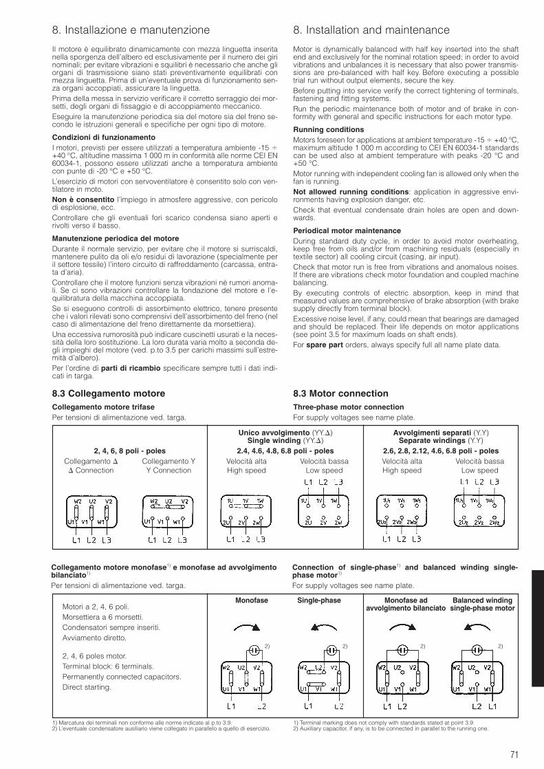
71
8. Installazione e manutenzione 8. Installation and maintenance
Il motore è equilibrato dinamicamente con mezza linguetta inseritanella sporgenza dell’albero ed esclusivamente per il numero dei girinominali; per evitare vibrazioni e squilibri è necessario che anche gliorgani di trasmissione siano stati preventivamente equilibrati conmezza linguetta. Prima di un’eventuale prova di funzionamento sen-za organi accoppiati, assicurare la linguetta.Prima della messa in servizio verificare il corretto serraggio dei mor-setti, degli organi di fissaggio e di accoppiamento meccanico.Eseguire la manutenzione periodica sia del motore sia del freno se-condo le istruzioni generali e specifiche per ogni tipo di motore.
Condizioni di funzionamentoI motori, previsti per essere utilizzati a temperatura ambiente -15 +40 °C, altitudine massima 1 000 m in conformità alle norme CEI EN60034-1, possono essere utilizzati anche a temperatura ambientecon punte di -20 °C e +50 °C.L’esercizio di motori con servoventilatore è consentito solo con ven-tilatore in moto.Non è consentito l’impiego in atmosfere aggressive, con pericolodi esplosione, ecc.Controllare che gli eventuali fori scarico condensa siano aperti erivolti verso il basso.
Manutenzione periodica del motoreDurante il normale servizio, per evitare che il motore si surriscaldi,mantenere pulito da oli e/o residui di lavorazione (specialmente peril settore tessile) l’intero circuito di raffreddamento (carcassa, entra-ta d’aria).Controllare che il motore funzioni senza vibrazioni né rumori anoma-li. Se ci sono vibrazioni controllare la fondazione del motore e l’e-quilibratura della macchina accoppiata.Se si eseguono controlli di assorbimento elettrico, tenere presenteche i valori rilevati sono comprensivi dell’assorbimento del freno (nelcaso di alimentazione del freno direttamente da morsettiera).Una eccessiva rumorosità può indicare cuscinetti usurati e la neces-sità della loro sostituzione. La loro durata varia molto a seconda de-gli impieghi del motore (ved. p.to 3.5 per carichi massimi sull’estre-mità d’albero).Per l’ordine di parti di ricambio specificare sempre tutti i dati indi-cati in targa.
8.3 Collegamento motoreCollegamento motore trifasePer tensioni di alimentazione ved. targa.
Motor is dynamically balanced with half key inserted into the shaftend and exclusively for the nominal rotation speed; in order to avoidvibrations and unbalances it is necessary that also power transmis-sions are pre-balanced with half key. Before executing a possibletrial run without output elements, secure the key.Before putting into service verify the correct tightening of terminals,fastening and fitting systems.Run the periodic maintenance both of motor and of brake in con-formity with general and specific instructions for each motor type.
Running conditionsMotors foreseen for applications at ambient temperature -15 +40 °C,maximum altitude 1 000 m according to CEI EN 60034-1 standardscan be used also at ambient temperature with peaks -20 °C and+50 °C.Motor running with independent cooling fan is allowed only when thefan is running.Not allowed running conditions: application in aggressive envi-ronments having explosion danger, etc.Check that eventual condensate drain holes are open and down-wards.
Periodical motor maintenanceDuring standard duty cycle, in order to avoid motor overheating,keep free from oils and/or from machining residuals (especially intextile sector) all cooling circuit (casing, air input).Check that motor run is free from vibrations and anomalous noises.If there are vibrations check motor foundation and coupled machinebalancing.By executing controls of electric absorption, keep in mind thatmeasured values are comprehensive of brake absorption (with brakesupply directly from terminal block).Excessive noise level, if any, could mean that bearings are damagedand should be replaced. Their life depends on motor applications(see point 3.5 for maximum loads on shaft ends).For spare part orders, always specify full all name plate data.
8.3 Motor connectionThree-phase motor connectionFor supply voltages see name plate.
Collegamento motore monofase1) e monofase ad avvolgimentobilanciato1)
Per tensioni di alimentazione ved. targa.
Connection of single-phase1) and balanced winding single-phase motor1)
For supply voltages see name plate.
1) Marcatura dei terminali non conforme alle norme indicate al p.to 3.9.2) L’eventuale condensatore ausiliario viene collegato in parallelo a quello di esercizio.
1) Terminal marking does not comply with standards stated at point 3.9.2) Auxiliary capacitor, if any, is to be connected in parallel to the running one.
Unico avvolgimento (YY.) Avvolgimenti separati (Y.Y)Single winding (YY.) Separate windings (Y.Y)
2, 4, 6, 8 poli - poles 2.4, 4.6, 4.8, 6.8 poli - poles 2.6, 2.8, 2.12, 4.6, 6.8 poli - polesCollegamento Collegamento Y Velocità alta Velocità bassa Velocità alta Velocità bassa
Connection Y Connection High speed Low speed High speed Low speed
Monofase Single-phase Monofase ad Balanced windingavvolgimento bilanciato single-phase motorMotori a 2, 4, 6 poli.
Morsettiera a 6 morsetti.Condensatori sempre inseriti.Avviamento diretto.
2, 4, 6 poles motor.Terminal block: 6 terminals.Permanently connected capacitors.Direct starting.
2) 2) 2) 2)
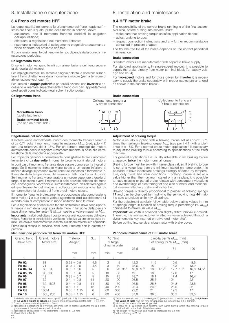
72
8. Installazione e manutenzione 8. Installation and maintenance
8.4 Freno del motore HFFLa responsabilità del corretto funzionamento del freno ricade sull’in-stallatore finale il quale, prima della messa in servizio, deve:– assicurarsi che il momento frenante soddisfi le esigenze
dell’applicazione;– effettuare la regolazione del momento frenante;– rispettare le indicazioni di collegamento e ogni altra raccomanda-
zione riportate nel presente capitolo.Il buon funzionamento del freno nel tempo dipende dalla corretta ma-nutenzione periodica.
Collegamento frenoDi serie i motori vengono forniti con alimentazione del freno separa-ta da quella del motore.Per impieghi normali, nei motori a singola polarità, è possibile alimen-tare il freno direttamente dalla morsettiera motore (per la tensione dialimentazione ved. cap. 4).Per i motori a doppia polarità e per quelli azionati con inverter è ne-cessario alimentare separatamente il freno con cavi appositamentepredisposti come indicato negli schemi sottoriportati.
Collegamento freno
8.4 HFF motor brakeThe responsibility of the correct brake running is of the final assem-bler who, before putting into service, must:– make sure that braking torque satisfies application needs;– adjust braking torque;– respect connection instructions and any further recommendation
contained in present chapter.The trouble-free life of the brake depends on the correct periodicalmaintenance.
Brake connectionStandard motors are manufactured with separate brake supply.For standard applications, in single-speed motors, it is possible tosupply the brake directly from motor terminal block (for supply volt-age see ch. 4).For two-speed motors and for those driven by inverter it is neces-sary to supply the brake separately with proper cables pre-arrangedas shown in the schemes below.
Brake connection
Regolazione del momento frenanteIl motore viene normalmente fornito con momento frenante tarato acirca 0,71 volte il momento frenante massimo Mfmax (ved. p.to 4.1)con una tolleranza del ± 18%. Per un corretto impiego del motoreautofrenante occorre regolare il momento frenante in base alle carat-teristiche della macchina accoppiata.Per impieghi generici è normalmente consigliabile tarare il momentofrenante a circa due volte il momento torcente nominale del motore.In ogni caso il momento frenante deve essere compreso fra i valori ditarga. Se il momento frenante viene tarato a un valore inferiore alminimo di targa si possono avere frenature incostanti e fortemente in-fluenzate dalla temperatura, dal sevizio e dalle condizioni di usura.Se il momento frenante viene tarato a un valore superiore a quello ditarga si possono avere il mancato o solo parziale sblocco del frenocon conseguenti vibrazioni e surriscaldamento dell’elettromagneteed eventualmente del motore e sollecitazioni meccaniche tali dacompromettere la durata del freno e del motore stesso.Il momento frenante è direttamente proporzionale alla compressionedelle molle 17 e può essere variato agendo sui dadi autobloccanti 44avendo cura di comprimere in modo uniforme tutte le molle.Per la regolazione attenersi alla tabella sottostante dove sono riporta-ti i valori in mm della lunghezza delle molle in funzione della percen-tuale di momento frenante (% Mfmax) rispetto al valore massimo Mfmax.Importante: i valori così ottenuti possono scostarsi leggermente dal valorevoluto. Pertanto, è consigliabile verificare l’effettivo valore conseguito tra-mite una chiave dinamometrica inserita sull’albero motore lato comando.Prima della messa in servizio, richiudere il motore con la calotta co-prifreno.Manutenzione periodica del freno del motore HFF
Adjustment of braking torqueMotor is usually supplied with a braking torque set at approx. 0,71times the maximum braking torque Mfmax (see point 4.1) with a toler-ance of ± 18%. For a correct brake motor application it is necessaryto adjust the braking torque according to specifications of the fittedmachine.For general applications it is usually advisable to set braking torqueat approx. twice the motor nominal torque.Braking torque must be set within name plate values. If braking torqueis set at a value less than the minimum stated on name plate, it ispossible to have inconstant brakings strongly affected by tempera-ture, duty cycle and wear conditions. If braking torque is set at avalue higher than the maximum stated on name plate, it is possibleto have missing or partial brake release with consequent vibrationsand overheatings of electromagnet and also of motor and mechani-cal stresses affecting brake and motor life.Braking torque is directly proportional to preload of braking springs17 and can be changed by modifying the self-locking nuts 44 mak-ing sure to preload uniformly all springs.For the adjustment carefully follow table below stating values in mmof springs length in function of braking torque percentage (% Mfmax)compared to maximum value Mfmax.Important: values thus obtained can slightly differ from value desired.Therefore, it is advisable to verify effective value achieved through adynamometric key inserted on drive end motor shaft.Before putting into service, close motor with brake cover.
Periodical maintenance of HFF motor brake
1) La tabella vale anche con freno a c.c. tipo FC (ved. p.to 4.1). In questo caso Mfmax diven-ta 0,8 volte il valore di tabella e il traferro max deve essere ridotto di 0,1 0,2 mm.
2) Spessore minimo del singolo disco freno.3) Nel caso di esecuzione HFFW (ved. schema), con le stesse lunghezze molla si otten-
gono momenti frenanti metà quelli di tabella.4) Nel caso di esecuzione HFFW aumentare il traferro di 0,1 mm.5) Valori riferiti a FA 14.
1) Table is also valid with d.c. brake type FC (see point 4.1). In this case Mfmax is 0,8 timesthe value of table and the max air-gap must be reduced by 0,1 0,2 mm.
2) Minimum thickness of brake single disk.3) In case of HFFW design (see scheme) with same spring length the braking torques
obtained will be the half of the table values.4) For design HFFW, the air gap must be increased by 0,1 mm.5) Value referring to FA 14.
Collegamento freno a brake connection
Collegamento freno a YY brake connection
Morsettiera freno(quella lato freno)Brake terminal block(the one on brake side)
Grand. freno Grand. motore Traferro Smin Mf [Nm] L molla per % Mfmax [mm]Brake size Motor size Air-gap di targa L of spring for % Mfmax [mm]
of name plate35,5 50 71 100
mm mm min max1) 4) 2) 3) 3)
FA 02 63 0,25 0,50 4,5 2 5, 35 12,2 11,5 10,5 8,5FA 03 71 0,25 0,50 4,5 3 10, 35 15,6 15 14,3 13,2FA 04, 14 80, 90 0,3 0,60 5 6 20 355) 18,8 185) 18,3 17,25) 17,7 165) 16,8 14,55)
FA 05, 15 90, 100 0,3 0,60 5 10 50, 35 19 18,5 17,8 17FA 06 112 0,35 0,70 5 15 75, 35 18,7 18,1 17,4 16,4FA 07 132 0,4 0,80 11 20 100, 35 26,5 25,5 24 22FA 08 132, 160S 0,4 0,80 11 30 150, 35 26,5 25,8 24,8 23,5FA 09 160 0,5 1,80 12 40 200, 35 25,4 24,6 23,5 22FA G9 180M 0,65 1,15 6 60 300, 35 22,2 21 19,3 17,2FA 10 180L, 200 0,65 1,15 6 80 400, 35 37,8 36,5 35,2 33,5
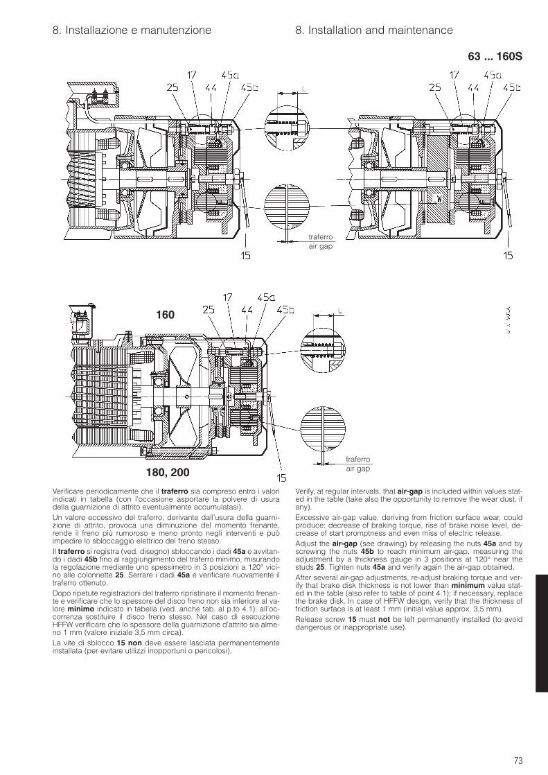
73
8. Installazione e manutenzione 8. Installation and maintenance
Verificare periodicamente che il traferro sia compreso entro i valoriindicati in tabella (con l’occasione asportare la polvere di usuradella guarnizione di attrito eventualmente accumulatasi).Un valore eccessivo del traferro, derivante dall’usura della guarni-zione di attrito, provoca una diminuzione del momento frenante,rende il freno più rumoroso e meno pronto negli interventi e puòimpedire lo sbloccaggio elettrico del freno stesso.Il traferro si registra (ved. disegno) sbloccando i dadi 45a e avvitan-do i dadi 45b fino al raggiungimento del traferro minimo, misurandola regolazione mediante uno spessimetro in 3 posizioni a 120° vici-no alle colonnette 25. Serrare i dadi 45a e verificare nuovamente iltraferro ottenuto.Dopo ripetute registrazioni del traferro ripristinare il momento frenan-te e verificare che lo spessore del disco freno non sia inferiore al va-lore minimo indicato in tabella (ved. anche tab. al p.to 4.1); all’oc-correnza sostituire il disco freno stesso. Nel caso di esecuzioneHFFW verificare che lo spessore della guarnizione d’attrito sia alme-no 1 mm (valore iniziale 3,5 mm circa).La vite di sblocco 15 non deve essere lasciata permanentementeinstallata (per evitare utilizzi inopportuni o pericolosi).
Verify, at regular intervals, that air-gap is included within values stat-ed in the table (take also the opportunity to remove the wear dust, ifany).Excessive air-gap value, deriving from friction surface wear, couldproduce: decrease of braking torque, rise of brake noise level, de-crease of start promptness and even miss of electric release.Adjust the air-gap (see drawing) by releasing the nuts 45a and byscrewing the nuts 45b to reach minimum air-gap, measuring theadjustment by a thickness gauge in 3 positions at 120° near thestuds 25. Tighten nuts 45a and verify again the air-gap obtained.After several air-gap adjustments, re-adjust braking torque and ver-ify that brake disk thickness is not lower than minimum value stat-ed in the table (also refer to table of point 4.1); if necessary, replacethe brake disk. In case of HFFW design, verify that the thickness offriction surface is at least 1 mm (initial value approx. 3,5 mm).Release screw 15 must not be left permanently installed (to avoiddangerous or inappropriate use).
63 ... 160S
160
180, 200
traferroair gap
traferroair gap
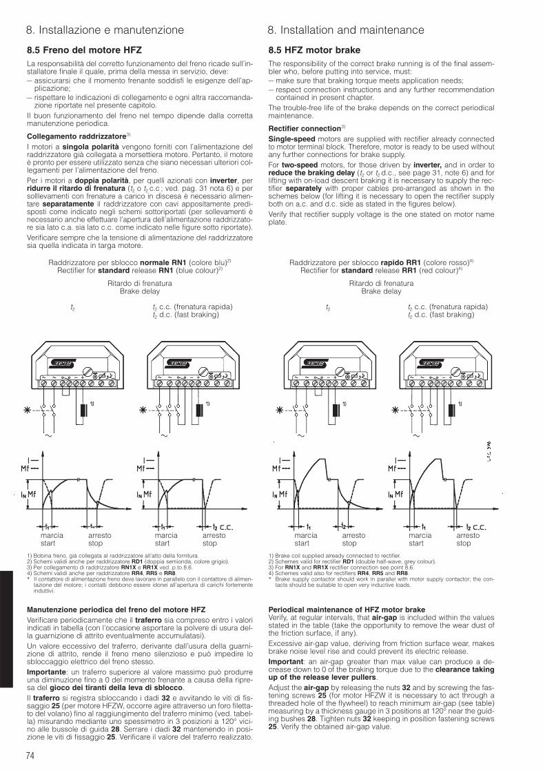
74
8. Installazione e manutenzione 8. Installation and maintenance
8.5 Freno del motore HFZLa responsabilità del corretto funzionamento del freno ricade sull’in-stallatore finale il quale, prima della messa in servizio, deve:– assicurarsi che il momento frenante soddisfi le esigenze dell’ap-
plicazione;– rispettare le indicazioni di collegamento e ogni altra raccomanda-
zione riportate nel presente capitolo.Il buon funzionamento del freno nel tempo dipende dalla correttamanutenzione periodica.
Collegamento raddrizzatore3)
I motori a singola polarità vengono forniti con l’alimentazione delraddrizzatore già collegata a morsettiera motore. Pertanto, il motoreè pronto per essere utilizzato senza che siano necessari ulteriori col-legamenti per l’alimentazione del freno.Per i motori a doppia polarità, per quelli azionati con inverter, perridurre il ritardo di frenatura (t2 o t2 c.c.; ved. pag. 31 nota 6) e persolllevamenti con frenature a carico in discesa è necessario alimen-tare separatamente il raddrizzatore con cavi appositamente predi-sposti come indicato negli schemi sottoriportati (per sollevamenti ènecessario anche effettuare l’apertura dell’alimentazione raddrizzato-re sia lato c.a. sia lato c.c. come indicato nelle figure sotto riportate).Verificare sempre che la tensione di alimentazione del raddrizzatoresia quella indicata in targa motore.
8.5 HFZ motor brakeThe responsibility of the correct brake running is of the final assem-bler who, before putting into service, must:– make sure that braking torque meets application needs;– respect connection instructions and any further recommendation
contained in present chapter.The trouble-free life of the brake depends on the correct periodicalmaintenance.
Rectifier connection3)
Single-speed motors are supplied with rectifier already connectedto motor terminal block. Therefore, motor is ready to be used withoutany further connections for brake supply.For two-speed motors, for those driven by inverter, and in order toreduce the braking delay (t2 or t2 d.c., see page 31, note 6) and forlifting with on-load descent braking it is necessary to supply the rec-tifier separately with proper cables pre-arranged as shown in theschemes below (for lifting it is necessary to open the rectifier supplyboth on a.c. and d.c. side as stated in the figures below).Verify that rectifier supply voltage is the one stated on motor nameplate.
Manutenzione periodica del freno del motore HFZVerificare periodicamente che il traferro sia compreso entro i valoriindicati in tabella (con l’occasione asportare la polvere di usura del-la guarnizione di attrito eventualmente accumulatasi).Un valore eccessivo del traferro, derivante dall’usura della guarni-zione di attrito, rende il freno meno silenzioso e può impedire losbloccaggio elettrico del freno stesso.Importante: un traferro superiore al valore massimo può produrreuna diminuzione fino a 0 del momento frenante a causa della ripre-sa del gioco dei tiranti della leva di sblocco.Il traferro si registra sbloccando i dadi 32 e avvitando le viti di fis-saggio 25 (per motore HFZW, occorre agire attraverso un foro filetta-to del volano) fino al raggiungimento del traferro minimo (ved. tabel-la) misurando mediante uno spessimetro in 3 posizioni a 120° vici-no alle bussole di guida 28. Serrare i dadi 32 mantenendo in posi-zione le viti di fissaggio 25. Verificare il valore del traferro realizzato.
Periodical maintenance of HFZ motor brakeVerify, at regular intervals, that air-gap is included within the valuesstated in the table (take the opportunity to remove the wear dust ofthe friction surface, if any).Excessive air-gap value, deriving from friction surface wear, makesbrake noise level rise and could prevent its electric release.Important: an air-gap greater than max value can produce a de-crease down to 0 of the braking torque due to the clearance takingup of the release lever pullers.Adjust the air-gap by releasing the nuts 32 and by screwing the fas-tening screws 25 (for motor HFZW it is necessary to act through athreaded hole of the flywheel) to reach minimum air-gap (see table)measuring by a thickness gauge in 3 positions at 120° near the guid-ing bushes 28. Tighten nuts 32 keeping in position fastening screws25. Verify the obtained air-gap value.
Raddrizzatore per sblocco normale RN1 (colore blu)2)
Rectifier for standard release RN1 (blue colour)2)
Ritardo di frenaturaBrake delay
t2 t2 c.c. (frenatura rapida)t2 d.c. (fast braking)
Raddrizzatore per sblocco rapido RR1 (colore rosso)4)
Rectifier for standard release RR1 (red colour)4)
Ritardo di frenaturaBrake delay
t2 t2 c.c. (frenatura rapida)t2 d.c. (fast braking)
1) Bobina freno, già collegata al raddrizzatore all’atto della fornitura.2) Schemi validi anche per raddrizzatore RD1 (doppia semionda, colore grigio). 3) Per collegamento di raddrizzatore RN1X e RR1X ved. p.to 8.6.4) Schemi validi anche per raddrizzatore RR4, RR5 e RR8.* Il contattore di alimentazione freno deve lavorare in parallelo con il contattore di alimen-
tazione del motore; i contatti debbono essere idonei all’apertura di carichi fortementeinduttivi.
1) Brake coil supplied already connected to rectifier.2) Schemes valid for rectifier RD1 (double half-wave, grey colour).3) For RN1X and RR1X rectifier connection see point 8.6.4) Schemes valid also for rectifiers RR4, RR5 and RR8.* Brake supply contactor should work in parallel with motor supply contactor; the con-
tacts should be suitable to open very inductive loads.
marcia arrestostart stop
marcia arrestostart stop
marcia arrestostart stop
marcia arrestostart stop
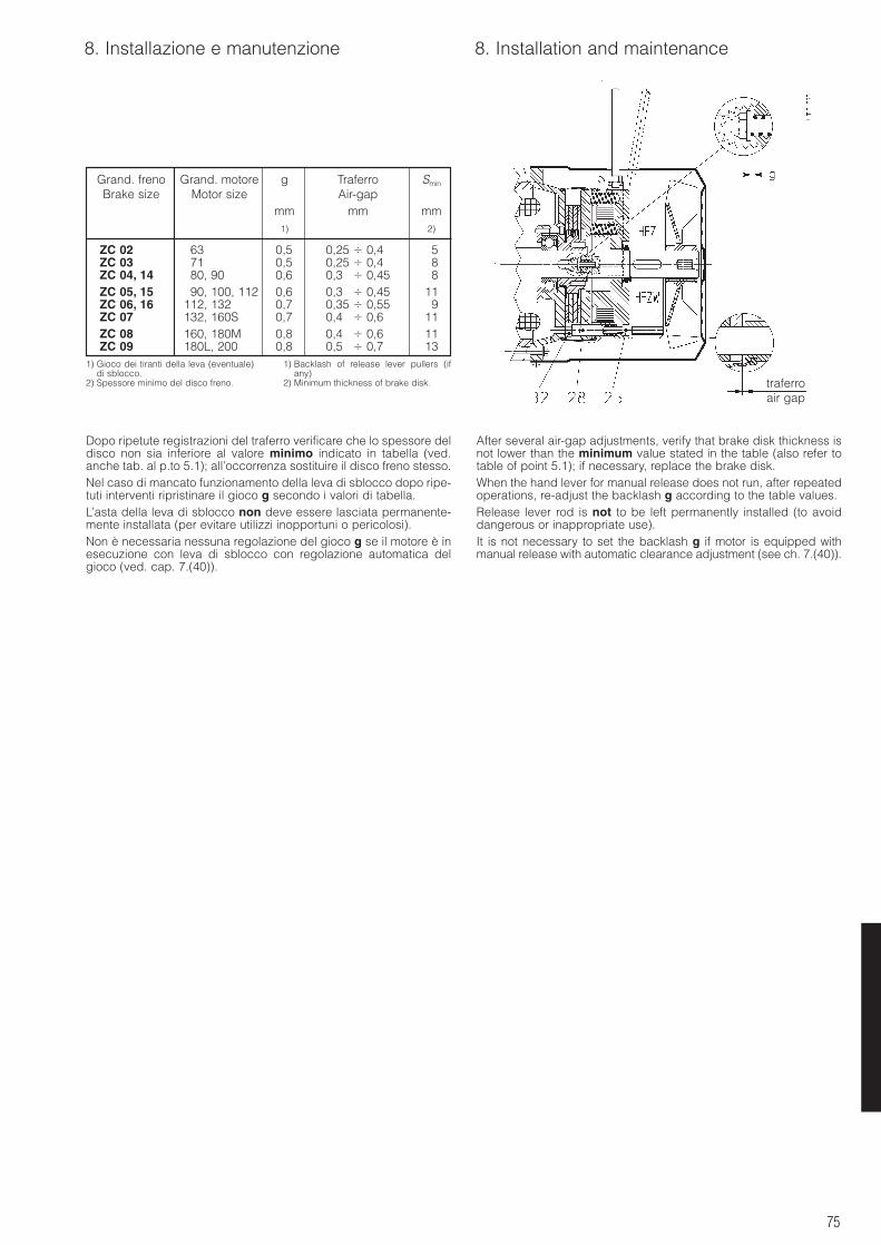
75
8. Installazione e manutenzione 8. Installation and maintenance
Dopo ripetute registrazioni del traferro verificare che lo spessore deldisco non sia inferiore al valore minimo indicato in tabella (ved.anche tab. al p.to 5.1); all’occorrenza sostituire il disco freno stesso.Nel caso di mancato funzionamento della leva di sblocco dopo ripe-tuti interventi ripristinare il gioco g secondo i valori di tabella.L’asta della leva di sblocco non deve essere lasciata permanente-mente installata (per evitare utilizzi inopportuni o pericolosi).Non è necessaria nessuna regolazione del gioco g se il motore è inesecuzione con leva di sblocco con regolazione automatica delgioco (ved. cap. 7.(40)).
After several air-gap adjustments, verify that brake disk thickness isnot lower than the minimum value stated in the table (also refer totable of point 5.1); if necessary, replace the brake disk.When the hand lever for manual release does not run, after repeatedoperations, re-adjust the backlash g according to the table values.Release lever rod is not to be left permanently installed (to avoiddangerous or inappropriate use).It is not necessary to set the backlash g if motor is equipped withmanual release with automatic clearance adjustment (see ch. 7.(40)).
Grand. freno Grand. motore g Traferro Smin
Brake size Motor size Air-gapmm mm mm
1) 2)
ZC 02 63 0,5 0,25 0,40 5ZC 03 71 0,5 0,25 0,40 8ZC 04, 14 80, 90 0,6 0,3 0,45 8ZC 05, 15 90, 100, 112 0,6 0,3 0,45 11ZC 06, 16 112, 132 0,7 0,35 0,55 9ZC 07 132, 160S 0,7 0,4 0,60 11ZC 08 160, 180M 0,8 0,4 0,60 11ZC 09 180L, 200 0,8 0,5 0,70 13
1) Gioco dei tiranti della leva (eventuale)di sblocco.
2) Spessore minimo del disco freno.
1) Backlash of release lever pullers (ifany)
2) Minimum thickness of brake disk. traferroair gap
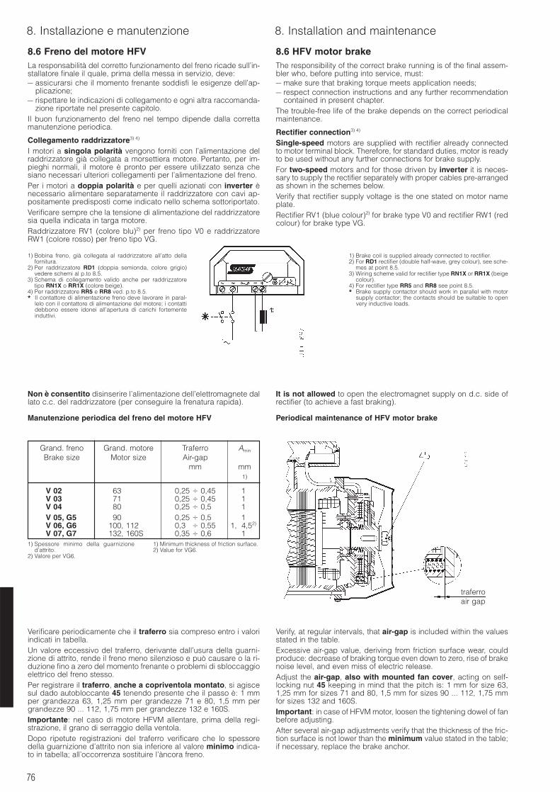
76
8. Installazione e manutenzione 8. Installation and maintenance
8.6 Freno del motore HFVLa responsabilità del corretto funzionamento del freno ricade sull’in-stallatore finale il quale, prima della messa in servizio, deve:– assicurarsi che il momento frenante soddisfi le esigenze dell’ap-
plicazione;– rispettare le indicazioni di collegamento e ogni altra raccomanda-
zione riportate nel presente capitolo.Il buon funzionamento del freno nel tempo dipende dalla correttamanutenzione periodica.
Collegamento raddrizzatore3) 4)
I motori a singola polarità vengono forniti con l’alimentazione delraddrizzatore già collegata a morsettiera motore. Pertanto, per im-pieghi normali, il motore è pronto per essere utilizzato senza chesiano necessari ulteriori collegamenti per l’alimentazione del freno.Per i motori a doppia polarità e per quelli azionati con inverter ènecessario alimentare separatamente il raddrizzatore con cavi ap-positamente predisposti come indicato nello schema sottoriportato.Verificare sempre che la tensione di alimentazione del raddrizzatoresia quella indicata in targa motore.Raddrizzatore RV1 (colore blu)2) per freno tipo V0 e raddrizzatoreRW1 (colore rosso) per freno tipo VG.
8.6 HFV motor brakeThe responsibility of the correct brake running is of the final assem-bler who, before putting into service, must:– make sure that braking torque meets application needs;– respect connection instructions and any further recommendation
contained in present chapter.The trouble-free life of the brake depends on the correct periodicalmaintenance.
Rectifier connection3) 4)
Single-speed motors are supplied with rectifier already connectedto motor terminal block. Therefore, for standard duties, motor is readyto be used without any further connections for brake supply.For two-speed motors and for those driven by inverter it is neces-sary to supply the rectifier separately with proper cables pre-arrangedas shown in the schemes below.Verify that rectifier supply voltage is the one stated on motor nameplate.Rectifier RV1 (blue colour)2) for brake type V0 and rectifier RW1 (redcolour) for brake type VG.
Non è consentito disinserire l’alimentazione dell’elettromagnete dallato c.c. del raddrizzatore (per conseguire la frenatura rapida).
Manutenzione periodica del freno del motore HFV
It is not allowed to open the electromagnet supply on d.c. side ofrectifier (to achieve a fast braking).
Periodical maintenance of HFV motor brake
Verificare periodicamente che il traferro sia compreso entro i valoriindicati in tabella.Un valore eccessivo del traferro, derivante dall’usura della guarni-zione di attrito, rende il freno meno silenzioso e può causare o la ri-duzione fino a zero del momento frenante o problemi di sbloccaggioelettrico del freno stesso.Per registrare il traferro, anche a copriventola montato, si agiscesul dado autobloccante 45 tenendo presente che il passo è: 1 mmper grandezza 63, 1,25 mm per grandezze 71 e 80, 1,5 mm pergrandezze 90 ... 112, 1,75 mm per grandezze 132 e 160S.Importante: nel caso di motore HFVM allentare, prima della regi-strazione, il grano di serraggio della ventola.Dopo ripetute registrazioni del traferro verificare che lo spessoredella guarnizione d’attrito non sia inferiore al valore minimo indica-to in tabella; all’occorrenza sostituire l’àncora freno.
Verify, at regular intervals, that air-gap is included within the valuesstated in the table.Excessive air-gap value, deriving from friction surface wear, couldproduce: decrease of braking torque even down to zero, rise of brakenoise level, and even miss of electric release.Adjust the air-gap, also with mounted fan cover, acting on self-locking nut 45 keeping in mind that the pitch is: 1 mm for size 63,1,25 mm for sizes 71 and 80, 1,5 mm for sizes 90 ... 112, 1,75 mmfor sizes 132 and 160S.Important: in case of HFVM motor, loosen the tightening dowel of fanbefore adjusting.After several air-gap adjustments verify that the thickness of the fric-tion surface is not lower than the minimum value stated in the table;if necessary, replace the brake anchor.
Grand. freno Grand. motore Traferro Amin
Brake size Motor size Air-gapmm mm
1)
V 02 63 0,25 0,45 1V 03 71 0,25 0,45 1V 04 80 0,25 0,50 1V 05, G5 90 0,25 0,50 1V 06, G6 100, 112 0,3 0,55 1, 4,52)
V 07, G7 132, 160S 0,35 0,60 11) Spessore minimo della guarnizione
d’attrito.2) Valore per VG6.
1) Minimum thickness of friction surface.2) Value for VG6.
1) Bobina freno, già collegata al raddrizzatore all’atto dellafornitura.
2) Per raddrizzatore RD1 (doppia semionda, colore grigio)vedere schemi al p.to 8.5.
3) Schema di collegamento valido anche per raddrizzatoretipo RN1X o RR1X (colore beige).
4) Per raddrizzatore RR5 e RR8 ved. p.to 8.5.* Il contattore di alimentazione freno deve lavorare in paral-
lelo con il contattore di alimentazione del motore; i contattidebbono essere idonei all’apertura di carichi fortementeinduttivi.
1) Brake coil is supplied already connected to rectifier.2) For RD1 rectifier (double half-wave, grey colour), see sche-
mes at point 8.5.3) Wiring scheme valid for rectifier type RN1X or RR1X (beige
colour).4) For rectifier type RR5 and RR8 see point 8.5.* Brake supply contactor should work in parallel with motor
supply contactor; the contacts should be suitable to openvery inductive loads.
traferroair gap
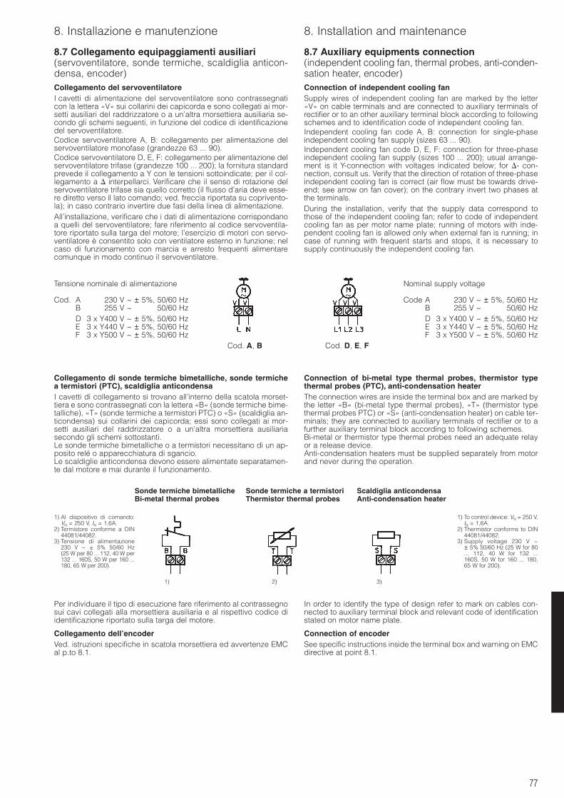
77
8. Installazione e manutenzione 8. Installation and maintenance
8.7 Collegamento equipaggiamenti ausiliari(servoventilatore, sonde termiche, scaldiglia anticon-densa, encoder)Collegamento del servoventilatoreI cavetti di alimentazione del servoventilatore sono contrassegnaticon la lettera «V» sui collarini dei capicorda e sono collegati ai mor-setti ausiliari del raddrizzatore o a un’altra morsettiera ausiliaria se-condo gli schemi seguenti, in funzione del codice di identificazionedel servoventilatore.Codice servoventilatore A, B: collegamento per alimentazione delservoventilatore monofase (grandezze 63 ... 90).Codice servoventilatore D, E, F: collegamento per alimentazione delservoventilatore trifase (grandezze 100 ... 200); la fornitura standardprevede il collegamento a Y con le tensioni sottoindicate; per il col-legamento a interpellarci. Verificare che il senso di rotazione delservoventilatore trifase sia quello corretto (il flusso d’aria deve esse-re diretto verso il lato comando; ved. freccia riportata su coprivento-la); in caso contrario invertire due fasi della linea di alimentazione.All’installazione, verificare che i dati di alimentazione corrispondanoa quelli del servoventilatore; fare riferimento al codice servoventila-tore riportato sulla targa del motore; l’esercizio di motori con servo-ventilatore è consentito solo con ventilatore esterno in funzione; nelcaso di funzionamento con marcia e arresto frequenti alimentarecomunque in modo continuo il servoventilatore.
8.7 Auxiliary equipments connection(independent cooling fan, thermal probes, anti-conden-sation heater, encoder)Connection of independent cooling fanSupply wires of independent cooling fan are marked by the letter«V» on cable terminals and are connected to auxiliary terminals ofrectifier or to an other auxiliary terminal block according to followingschemes and to identification code of independent cooling fan.Independent cooling fan code A, B: connection for single-phaseindependent cooling fan supply (sizes 63 ... 90).Independent cooling fan code D, E, F: connection for three-phaseindependent cooling fan supply (sizes 100 ... 200); usual arrange-ment is it Y-connection with voltages indicated below; for - con-nection, consult us. Verify that the direction of rotation of three-phaseindependent cooling fan is correct (air flow must be towards drive-end; see arrow on fan cover); on the contrary invert two phases atthe terminals.During the installation, verify that the supply data correspond tothose of the independent cooling fan; refer to code of independentcooling fan as per motor name plate; running of motors with inde-pendent cooling fan is allowed only when external fan is running; incase of running with frequent starts and stops, it is necessary tosupply continuously the independent cooling fan.
Collegamento di sonde termiche bimetalliche, sonde termichea termistori (PTC), scaldiglia anticondensaI cavetti di collegamento si trovano all’interno della scatola morset-tiera e sono contrassegnati con la lettera «B» (sonde termiche bime-talliche), «T» (sonde termiche a termistori PTC) o «S» (scaldiglia an-ticondensa) sui collarini dei capicorda; essi sono collegati ai mor-setti ausiliari del raddrizzatore o a un’altra morsettiera ausiliariasecondo gli schemi sottostanti.Le sonde termiche bimetalliche o a termistori necessitano di un ap-posito relé o apparecchiatura di sgancio.Le scaldiglie anticondensa devono essere alimentate separatamen-te dal motore e mai durante il funzionamento.
Connection of bi-metal type thermal probes, thermistor typethermal probes (PTC), anti-condensation heaterThe connection wires are inside the terminal box and are marked bythe letter «B» (bi-metal type thermal probes), «T» (thermistor typethermal probes PTC) or «S» (anti-condensation heater) on cable ter-minals; they are connected to auxiliary terminals of rectifier or to afurther auxiliary terminal block according to following schemes.Bi-metal or thermistor type thermal probes need an adequate relayor a release device.Anti-condensation heaters must be supplied separately from motorand never during the operation.
Per individuare il tipo di esecuzione fare riferimento al contrassegnosui cavi collegati alla morsettiera ausiliaria e al rispettivo codice diidentificazione riportato sulla targa del motore.
Collegamento dell’encoderVed. istruzioni specifiche in scatola morsettiera ed avvertenze EMCal p.to 8.1.
In order to identify the type of design refer to mark on cables con-nected to auxiliary terminal block and relevant code of identificationstated on motor name plate.
Connection of encoderSee specific instructions inside the terminal box and warning on EMCdirective at point 8.1.
Sonde termiche bimetallicheBi-metal thermal probes
Sonde termiche a termistoriThermistor thermal probes
Scaldiglia anticondensaAnti-condensation heater
Tensione nominale di alimentazione
Cod. A 230 V ~ ± 5%, 50/60 HzB 255 V ~ ± 5%, 50/60 HzD 3 x Y400 V ~ ± 5%, 50/60 HzE 3 x Y440 V ~ ± 5%, 50/60 HzF 3 x Y500 V ~ ± 5%, 50/60 Hz
Nominal supply voltage
Code A 230 V ~ ± 5%, 50/60 HzB 255 V ~ ± 5%, 50/60 HzD 3 x Y400 V ~ ± 5%, 50/60 HzE 3 x Y440 V ~ ± 5%, 50/60 HzF 3 x Y500 V ~ ± 5%, 50/60 Hz
1) Al dispositivo di comando:VN = 250 V, IN = 1,6A.
2) Termistore conforme a DIN44081/44082.
3) Tensione di alimentazione230 V ~ ± 5% 50/60 Hz(25 W per 80 ... 112, 40 W per132 ... 160S, 50 W per 160 ...180, 65 W per 200).
1) To control device: VN = 250 V,IN = 1,6A.
2) Thermistor conforms to DIN44081/44082.
3) Supply voltage 230 V ~± 5% 50/60 Hz (25 W for 80... 112, 40 W for 132 ...160S, 50 W for 160 ... 180,65 W for 200).
1) 2) 3)
Cod. A, B Cod. D, E, F
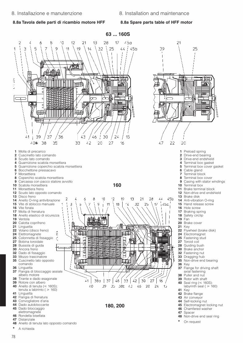
78
8. Installazione e manutenzione 8. Installation and maintenance
8.8a Tavola delle parti di ricambio motore HFF 8.8a Spare parts table of HFF motor
63 ... 160S
160
180, 200
1 Preload spring2 Drive-end bearing3 Drive-end endshield4 Terminal box gasket5 Terminal box cover gasket6 Cable gland7 Terminal block8 Terminal box cover9 Casing with stator windings
10 Terminal box11 Brake terminal block12 Non-drive end endshield13 Brake disk14 Anti-vibration O-ring15 Hand release screw16 Hole screw17 Braking spring18 Safety circlip19 Fan20 Brake cover21 Key22 Flywheel (brake disk)24 Electromagnet25 Fastening stud27 Toroid coil28 Guiding bush30 Brake anchor32 Fastening nut33 Dragging hub35 Non-drive end bearing36 Key37 Flange for driving shaft
axial fastening38 Puller and nut39 Rotor with shaft40 Seal ring ( 160S);
labyrinth seal ( 160)41 Key42 Brake flange43 Air conveyor44 Self-locking nut45 Electromagnet locking nut46 Chamfered washer47 Spacer48 Non-drive end seal ring
* On request
1 Molla di precarico2 Cuscinetto lato comando3 Scudo lato comando4 Guarnizione scatola morsettiera5 Guarnizione coperchio scatola morsettiera6 Bocchettone pressacavo7 Morsettiera8 Coperchio scatola morsettiera9 Carcassa con pacco statore avvolto
10 Scatola morsettiera11 Morsettiera freno12 Scudo lato opposto comando13 Disco freno14 Anello O-ring antivibrazione15 Vite di sblocco manuale16 Vite forata17 Molla di frenatura18 Anello elastico di sicurezza19 Ventola20 Calotta coprifreno21 Linguetta22 Volano (disco freno)24 Elettromagnete25 Colonnetta di fissaggio27 Bobina toroidale28 Bussola di guida30 Ancora freno32 Dado di fissaggio33 Mozzo trascinatore35 Cuscinetto lato opposto
comando36 Linguetta37 Flangia di bloccaggio assiale
albero motore38 Tirante e dado esagonale39 Rotore con albero40 Anello di tenuta ( 160S);
tenuta a labirinto ( 160)41 Linguetta42 Flangia di frenatura43 Convogliatore d’aria44 Dado autobloccante45 Dado bloccaggio
elettromagnete46 Rondella bisellata47 Distanziale48 Anello di tenuta lato opposto comando
* A richiesta
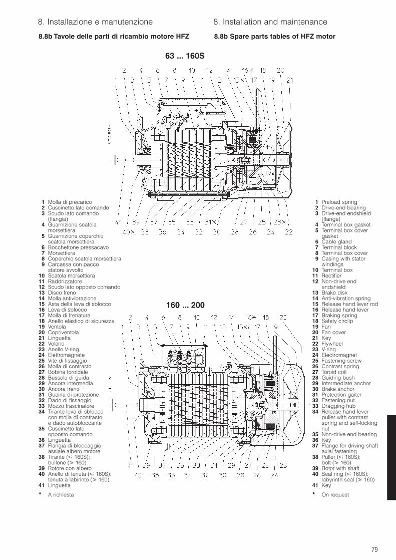
79
8. Installazione e manutenzione 8. Installation and maintenance
8.8b Tavole delle parti di ricambio motore HFZ 8.8b Spare parts tables of HFZ motor
63 ... 160S
160 ... 200
1 Molla di precarico2 Cuscinetto lato comando3 Scudo lato comando
(flangia)4 Guarnizione scatola
morsettiera5 Guarnizione coperchio
scatola morsettiera6 Bocchettone pressacavo7 Morsettiera8 Coperchio scatola morsettiera9 Carcassa con pacco
statore avvolto10 Scatola morsettiera11 Raddrizzatore12 Scudo lato opposto comando13 Disco freno14 Molla antivibrazione15 Asta della leva di sblocco16 Leva di sblocco17 Molla di frenatura18 Anello elastico di sicurezza19 Ventola20 Copriventola21 Linguetta22 Volano23 Anello V-ring24 Elettromagnete25 Vite di fissaggio26 Molla di contrasto27 Bobina toroidale28 Bussola di guida29 Àncora intermedia30 Àncora freno31 Guaina di protezione32 Dado di fissaggio33 Mozzo trascinatore34 Tirante leva di sblocco
con molla di contrastoe dado autobloccante
35 Cuscinetto latoopposto comando
36 Linguetta37 Flangia di bloccaggio
assiale albero motore38 Tirante ( 160S);
bullone ( 160) 39 Rotore con albero40 Anello di tenuta ( 160S);
tenuta a labirinto ( 160)41 Linguetta
* A richiesta
1 Preload spring2 Drive-end bearing3 Drive-end endshield
(flange)4 Terminal box gasket5 Terminal box cover
gasket6 Cable gland7 Terminal block8 Terminal box cover9 Casing with stator
windings10 Terminal box11 Rectifier12 Non-drive end
endshield13 Brake disk14 Anti-vibration spring15 Release hand lever rod16 Release hand lever17 Braking spring18 Safety circlip19 Fan20 Fan cover21 Key22 Flywheel23 V-ring24 Electromagnet25 Fastening screw26 Contrast spring27 Toroid coil28 Guiding bush29 Intermediate anchor30 Brake anchor31 Protection gaiter32 Fastening nut33 Dragging hub34 Release hand lever
puller with contrastspring and self-lockingnut
35 Non-drive end bearing36 Key37 Flange for driving shaft
axial fastening38 Puller ( 160S);
bolt ( 160) 39 Rotor with shaft40 Seal ring ( 160S);
labyrinth seal ( 160)41 Key
* On request
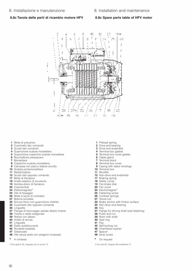
80
8. Installazione e manutenzione 8. Installation and maintenance
8.8c Tavola delle parti di ricambio motore HFV 8.8c Spare parts table of HFV motor
1 Molla di precarico2 Cuscinetto lato comando3 Scudo lato comando4 Guarnizione scatola morsettiera5 Guarnizione coperchio scatola morsettiera6 Bocchettone pressacavo7 Morsettiera8 Coperchio scatola morsettiera9 Carcassa con pacco statore avvolto
10 Scatola portamorsettiera11 Raddrizzatore12 Scudo lato opposto comando17 Molla di frenatura18 Anello elastico di sicurezza19 Ventola-disco di frenatura20 Copriventola24 Elettromagnete1)
25 Vite di fissaggio26 Molle a tazza di contrasto27 Bobina toroidale30 Àncora freno con guarnizione d’attrito35 Cuscinetto lato opposto comando36 Linguetta37 Flangia di bloccaggio assiale albero motore38 Tirante e dado esagonale39 Rotore con albero40 Anello di tenuta41 Linguetta45 Dado autobloccante46 Rondella bisellata47 Distanziale48 Vite senza testa con esagono incassato
* A richiesta
1) Per grand. 63, integrale con lo scudo 12
1 Preload spring2 Drive end bearing3 Drive end endshield4 Terminal box gasket5 Terminal box cover gasket6 Cable gland7 Terminal block8 Terminal box cover9 Casing with stator windings
10 Terminal box11 Rectifier12 Non-drive end endshield17 Braking spring18 Safety circlip19 Fan-brake disk20 Fan cover24 Electromagnet1)
25 Fastening screw26 Contrast springs27 Toroid coil30 Brake anchor with friction surface35 Non-drive end bearing36 Key37 Flange for driving shaft axial fastening38 Puller and nut39 Rotor with shaft40 Seal ring41 Key45 Self-locking nut46 Chamfered washer47 Spacer48 Grub screw
* On request
1) For size 63, integral with endshiled 12
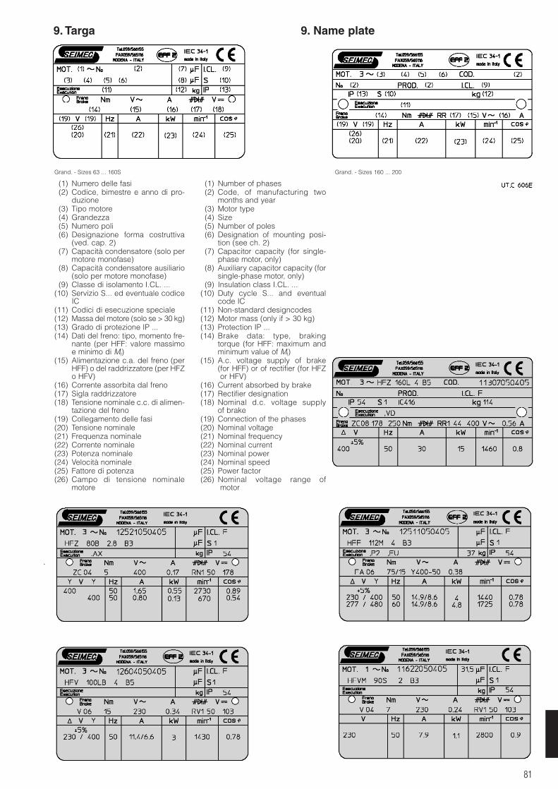
81
9. Targa 9. Name plate
Grand. - Sizes 63 ... 160S
(1) Numero delle fasi(2) Codice, bimestre e anno di pro-
duzione(3) Tipo motore(4) Grandezza(5) Numero poli(6) Designazione forma costruttiva
(ved. cap. 2)(7) Capacità condensatore (solo per
motore monofase)(8) Capacità condensatore ausiliario
(solo per motore monofase)(9) Classe di isolamento I.CL. ...
(10) Servizio S... ed eventuale codiceIC
(11) Codici di esecuzione speciale(12) Massa del motore (solo se > 30 kg)(13) Grado di protezione IP ...(14) Dati del freno: tipo, momento fre-
nante (per HFF: valore massimoe minimo di Mf)
(15) Alimentazione c.a. del freno (perHFF) o del raddrizzatore (per HFZo HFV)
(16) Corrente assorbita dal freno(17) Sigla raddrizzatore(18) Tensione nominale c.c. di alimen-
tazione del freno(19) Collegamento delle fasi(20) Tensione nominale(21) Frequenza nominale(22) Corrente nominale(23) Potenza nominale(24) Velocità nominale(25) Fattore di potenza(26) Campo di tensione nominale
motore
Grand. - Sizes 160 ... 200
(1) Number of phases(2) Code, of manufacturing two
months and year(3) Motor type(4) Size(5) Number of poles(6) Designation of mounting posi-
tion (see ch. 2)(7) Capacitor capacity (for single-
phase motor, only)(8) Auxiliary capacitor capacity (for
single-phase motor, only)(9) Insulation class I.CL. ...
(10) Duty cycle S... and eventualcode IC
(11) Non-standard designcodes(12) Motor mass (only if > 30 kg)(13) Protection IP ...(14) Brake data: type, braking
torque (for HFF: maximum andminimum value of Mf)
(15) A.c. voltage supply of brake (for HFF) or of rectifier (for HFZor HFV)
(16) Current absorbed by brake(17) Rectifier designation(18) Nominal d.c. voltage supply
of brake(19) Connection of the phases(20) Nominal voltage(21) Nominal frequency(22) Nominal current(23) Nominal power(24) Nominal speed(25) Power factor(26) Nominal voltage range of
motor

82

83
CO
D. 0
0009
0785
- M
oden
aC
at.2
2
005
- IT
EN
-1
000
0
3.05
/0
S.E.I.M.E.C. S.p.A.Via Archimede, 115 (P.O. BOX 2)41010 LIMIDI DI SOLIERA (MODENA) - ITALIA
Tel. 059 56 61 55 - Fax 059 56 51 [email protected]
CATALOGO 1 CATALOGUE 1
HF Motori asincroni trifase Asynchronous three-phase motorsgrand. - sizes 63 ... 315S; pol. 2, 4, 6, 8, 2.4, 2.6, 2.8, 2.12, 4.6, 4.8, 6.8; PN 0,045 ... 110 kW
HFM Motori asincroni monofase Asynchronous single-phase motorsgrand. - sizes 63 ... 100; pol. 2, 4, 6; PN 0,09 ... 3 kW
CATALOGO 2 CATALOGUE 2
HFF Motori autofrenanti asincroni trifase Asynchronous three-phase brake motorscon freno a c.a. with a.c. brakegrand. - sizes 63 ... 200; pol. 2, 4, 6, 8, 2.4, 2.6, 2.8, 2.12, 4.6, 4.8, 6.8; PN 0,045 ... 37 kW
HFZ Motori autofrenanti asincroni trifase Asynchronous three-phase brake motorscon freno a c.c. with d.c. brakegrand. - sizes 63 ... 200; pol. 2, 4, 6, 8, 2.4, 2.6, 2.8, 2.12, 4.6, 4.8, 6.8; PN 0,045 ... 37 kW
HFV Motori autofrenanti asincroni trifase Asynchronous three-phase brake motorscon freno di sicurezza a c.c. with d.c. safety brakegrand. - sizes 63 ... 160S; pol. 2, 4, 6, 8, 2.4, 2.6, 2.8, 2.12, 4.6, 4.8, 6.8; PN 0,045 ... 15 kW
HFVM Motori autofrenanti asincroni monofase Asynchronous single-phase brake motorscon freno di sicurezza a c.c. with d.c. safety brakegrand. - sizes 63 ... 100; pol. 2, 4, 6; PN 0,09 ... 3 kW
CATALOGO 3 CATALOGUE 3
HPE Motori asincroni trifase piatti estrusi Asynchronous three-phase flat extrudedgrand. - sizes 50 ... 80; pol. 2, 4, 2.4; motors PN 0,18 ... 9,2 kW
HPEM Motori asincroni monofase piatti estrusi Asynchronous single-phase flat extrudedgrand. - sizes 50 ... 71; pol. 2; motors PN 0,27 ... 2,2 kW
HPEV Motori asincroni trifase piatti Asynchronous three-phase flat extrudedestrusi con freno di sicurezza a c.c. motors with d.c. safety brakegrand. - sizes 50 ... 80; pol. 2, 4, 2.4; PN 0,18 ... 9,2 kW
HPEVM Motori asincroni monofase piatti Asynchronous single-phase flat extrudedestrusi con freno di sicurezza a c.c. motors with d.c. safety brakegrand. - sizes 50 ... 71; pol. 2; PN 0,27 ... 2,2 kW