Embed Size (px)
Citation preview
31 JANUARY 1995
S9086–T9–STM–010/CH–594
FIRST REVISION
NAVAL SHIPS’ TECHNICAL MANUAL
CHAPTER 594
SALVAGE – SUBMARINE SAFETYESCAPE AND RESCUE DEVICES
THIS CHAPTER SUPERSEDES CHAPTER 594 DATED 1 AUGUST 1981
DISTRIBUTION STATEMENT C: DISTRIBUTION AUTHORIZED TO GOVERNMENT AGENCIES AND THEIR CON-
TRACTORS: ADMINISTRATIVE AND OPERATIONAL USE. (1 AUGUST 1981) OTHER REQUESTS SHALL BE REFERRED TO
THE NAVAL SEA SYSTEMS COMMAND (SEA–56Z11).
DESTRUCTION NOTICE: DESTROY BY ANY METHOD THAT WILL PREVENT DISCLOSURE OF CONTENTS OR RE-
CONSTRUCTION OF THE DOCUMENT.
PUBLISHED BY DIRECTION OF COMMANDER, NAVAL SEA SYSTEMS COMMAND.
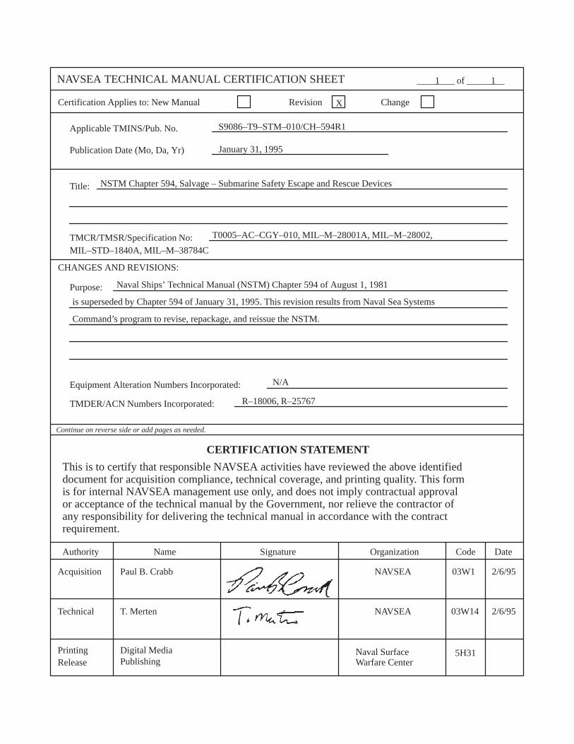
NAVSEA TECHNICAL MANUAL CERTIFICATION SHEET ________ of ________
Certification Applies to: New Manual Revision Change
Applicable TMINS/Pub. No.
Publication Date (Mo, Da, Yr)
Title:
TMCR/TMSR/Specification No:
CHANGES AND REVISIONS:
Purpose:
Equipment Alteration Numbers Incorporated:
TMDER/ACN Numbers Incorporated:
Continue on reverse side or add pages as needed.
CERTIFICATION STATEMENT
This is to certify that responsible NAVSEA activities have reviewed the above identifieddocument for acquisition compliance, technical coverage, and printing quality. This formis for internal NAVSEA management use only, and does not imply contractual approval or acceptance of the technical manual by the Government, nor relieve the contractor ofany responsibility for delivering the technical manual in accordance with the contract requirement.
Code DateAuthority
Acquisition
Technical
Printing Release
1 1
X
S9086–T9–STM–010/CH–594R1
January 31, 1995
NSTM Chapter 594, Salvage – Submarine Safety Escape and Rescue Devices
Digital MediaPublishing
Name Signature Organization
Naval Ships’ Technical Manual (NSTM) Chapter 594 of August 1, 1981
Paul B. Crabb NAVSEA 03W1 2/6/95
T. Merten NAVSEA 03W14 2/6/95
is superseded by Chapter 594 of January 31, 1995. This revision results from Naval Sea Systems
Command’s program to revise, repackage, and reissue the NSTM.
N/A
R–18006, R–25767
Naval SurfaceWarfare Center
5H31
T0005–AC–CGY–010, MIL–M–28001A, MIL–M–28002,
MIL–STD–1840A, MIL–M–38784C
TABLE OF CONTENTS
S9086–T9–STM–010/CH–594R1
i
CHAPTER 594SALVAGE – SUBMARINE SAFETYESCAPE AND RESCUE DEVICES
SECTION 1. SUBMARINE ABANDONMENT
Paragraph Page
594–1.1 CAUSES OF SUBMARINE ABANDONMENT 1–1. . . . . . . . . . . . . . . . . . . . . . . . . . . . . . 594–1.1.1 DESCRIPTION 1–1. . . . . . . . . . . . . . . . . . . . . . . . . . . . . . . . . . . . . . . . . . . . . . . . . . . . 594–1.2 FACTORS INFLUENCING SUBMARINE ABANDONMENT 1–1. . . . . . . . . . . . . . . . . . 594–1.2.1 GENERAL 1–1. . . . . . . . . . . . . . . . . . . . . . . . . . . . . . . . . . . . . . . . . . . . . . . . . . . . . . . . 594–1.2.2 RESCUE AND ESCAPE OPERATIONS 1–1. . . . . . . . . . . . . . . . . . . . . . . . . . . . . . . . 594–1.2.3 RESCUE SYSTEM DEPLOYMENT 1–2. . . . . . . . . . . . . . . . . . . . . . . . . . . . . . . . . . . 594–1.2.4 CRITERIA FOR ESCAPE OR RESCUE 1–2. . . . . . . . . . . . . . . . . . . . . . . . . . . . . . . . 594–1.2.4.1 Criteria Supporting the Decision to Escape 1–2. . . . . . . . . . . . . . . . . . . . . . . . . . . 594–1.2.4.2 Criteria Supporting the Decision to Await Rescue 1–5. . . . . . . . . . . . . . . . . . . . . 594–1.2.5 COMMUNICATING THE SUBMARINE’S LOCATION 1–5. . . . . . . . . . . . . . . . . . . 594–1.2.6 COMMUNICATING THE SUBMARINE’S CONDITION 1–5. . . . . . . . . . . . . . . . . .
SECTION 2. COLLECTIVE RESCUE USING SUBMARINE RESCUE CHAMBER
594–2.1 SUBMARINE RESCUE CHAMBER (SRC) 2–1. . . . . . . . . . . . . . . . . . . . . . . . . . . . . . . . . . 594–2.1.1 GENERAL IDENTIFICATION 2–1. . . . . . . . . . . . . . . . . . . . . . . . . . . . . . . . . . . . . . . . 594–2.1.2 DESCRIPTION 2–1. . . . . . . . . . . . . . . . . . . . . . . . . . . . . . . . . . . . . . . . . . . . . . . . . . . . 594–2.1.3 EXTERIOR FEATURES 2–1. . . . . . . . . . . . . . . . . . . . . . . . . . . . . . . . . . . . . . . . . . . . . 594–2.1.4 UPPER COMPARTMENT 2–1. . . . . . . . . . . . . . . . . . . . . . . . . . . . . . . . . . . . . . . . . . . 594–2.1.4.1 Air Motor 2–3. . . . . . . . . . . . . . . . . . . . . . . . . . . . . . . . . . . . . . . . . . . . . . . . . . . . . 594–2.1.4.2 Ballast 2–3. . . . . . . . . . . . . . . . . . . . . . . . . . . . . . . . . . . . . . . . . . . . . . . . . . . . . . . 594–2.1.4.3 Instrumentation 2–3. . . . . . . . . . . . . . . . . . . . . . . . . . . . . . . . . . . . . . . . . . . . . . . . 594–2.1.4.4 Electrical Equipment 2–3. . . . . . . . . . . . . . . . . . . . . . . . . . . . . . . . . . . . . . . . . . . . 594–2.1.4.5 Communication Equipment 2–3. . . . . . . . . . . . . . . . . . . . . . . . . . . . . . . . . . . . . . . 594–2.1.4.6 Viewports 2–3. . . . . . . . . . . . . . . . . . . . . . . . . . . . . . . . . . . . . . . . . . . . . . . . . . . . . 594–2.1.5 LOWER COMPARTMENT 2–3. . . . . . . . . . . . . . . . . . . . . . . . . . . . . . . . . . . . . . . . . . . 594–2.1.5.1 Downhaul Equipment 2–3. . . . . . . . . . . . . . . . . . . . . . . . . . . . . . . . . . . . . . . . . . . 594–2.1.5.2 Hold–Down Devices 2–4. . . . . . . . . . . . . . . . . . . . . . . . . . . . . . . . . . . . . . . . . . . . 594–2.1.6 BALLAST TANK 2–4. . . . . . . . . . . . . . . . . . . . . . . . . . . . . . . . . . . . . . . . . . . . . . . . . . 594–2.1.7 PIPING SYSTEMS 2–4. . . . . . . . . . . . . . . . . . . . . . . . . . . . . . . . . . . . . . . . . . . . . . . . .
TABLE OF CONTENTS (Continued)
Paragraph Page
S9086–T9–STM–010/CH–594R1
ii
594–2.1.7.1 Air System 2–6. . . . . . . . . . . . . . . . . . . . . . . . . . . . . . . . . . . . . . . . . . . . . . . . . . . . 594–2.1.7.2 Flood and Drain System 2–6. . . . . . . . . . . . . . . . . . . . . . . . . . . . . . . . . . . . . . . . . 594–2.1.7.3 Spill and Vent System 2–6. . . . . . . . . . . . . . . . . . . . . . . . . . . . . . . . . . . . . . . . . . . 594–2.1.7.4 Hydraulic System 2–6. . . . . . . . . . . . . . . . . . . . . . . . . . . . . . . . . . . . . . . . . . . . . . . 594–2.1.7.5 Emergency Breathing System 2–6. . . . . . . . . . . . . . . . . . . . . . . . . . . . . . . . . . . . . 594–2.1.7.6 Exhaust and Vent System 2–6. . . . . . . . . . . . . . . . . . . . . . . . . . . . . . . . . . . . . . . . . 594–2.1.8 MISCELLANEOUS EQUIPMENT 2–6. . . . . . . . . . . . . . . . . . . . . . . . . . . . . . . . . . . . 594–2.1.8.1 Hoses 2–6. . . . . . . . . . . . . . . . . . . . . . . . . . . . . . . . . . . . . . . . . . . . . . . . . . . . . . . . 594–2.1.8.2 Communication Cable 2–6. . . . . . . . . . . . . . . . . . . . . . . . . . . . . . . . . . . . . . . . . . . 594–2.1.8.3 Backhaul Line 2–6. . . . . . . . . . . . . . . . . . . . . . . . . . . . . . . . . . . . . . . . . . . . . . . . . 594–2.1.8.4 Lifting Pendant 2–6. . . . . . . . . . . . . . . . . . . . . . . . . . . . . . . . . . . . . . . . . . . . . . . . 594–2.1.8.5 Miscellaneous Tool Bag 2–7. . . . . . . . . . . . . . . . . . . . . . . . . . . . . . . . . . . . . . . . . 594–2.1.8.6 Battle Lanterns 2–7. . . . . . . . . . . . . . . . . . . . . . . . . . . . . . . . . . . . . . . . . . . . . . . . . 594–2.1.8.7 Lower Hatch Lifting Tackle 2–7. . . . . . . . . . . . . . . . . . . . . . . . . . . . . . . . . . . . . . . 594–2.1.8.8 Protective Headgear 2–7. . . . . . . . . . . . . . . . . . . . . . . . . . . . . . . . . . . . . . . . . . . . . 594–2.2 SRC RESCUE OPERATIONS 2–7. . . . . . . . . . . . . . . . . . . . . . . . . . . . . . . . . . . . . . . . . . . . . 594–2.2.1 GENERAL 2–7. . . . . . . . . . . . . . . . . . . . . . . . . . . . . . . . . . . . . . . . . . . . . . . . . . . . . . . .
SECTION 3. COLLECTIVE RESCUE USING DEEP SUBMERGENCERESCUE VEHICLE
594–3.1 DEEP SUBMERGENCE RESCUE VEHICLE (DSRV) 3–1. . . . . . . . . . . . . . . . . . . . . . . . . 594–3.1.1 GENERAL 3–1. . . . . . . . . . . . . . . . . . . . . . . . . . . . . . . . . . . . . . . . . . . . . . . . . . . . . . . . 594–3.1.2 DESCRIPTION 3–1. . . . . . . . . . . . . . . . . . . . . . . . . . . . . . . . . . . . . . . . . . . . . . . . . . . . 594–3.1.3 DSRV SKIRT 3–1. . . . . . . . . . . . . . . . . . . . . . . . . . . . . . . . . . . . . . . . . . . . . . . . . . . . . . 594–3.1.4 DSRV PROPULSION AND CONTROL 3–1. . . . . . . . . . . . . . . . . . . . . . . . . . . . . . . . 594–3.2 DSRV RESCUE OPERATIONS 3–1. . . . . . . . . . . . . . . . . . . . . . . . . . . . . . . . . . . . . . . . . . . 594–3.2.1 GENERAL 3–1. . . . . . . . . . . . . . . . . . . . . . . . . . . . . . . . . . . . . . . . . . . . . . . . . . . . . . . .
SECTION 4. INDIVIDUAL ESCAPE USING THE RESCUE/ESCAPE TRUNK
594–4.1 INDIVIDUAL ESCAPE 4–1. . . . . . . . . . . . . . . . . . . . . . . . . . . . . . . . . . . . . . . . . . . . . . . . . . 594–4.1.1 DEFINITION 4–1. . . . . . . . . . . . . . . . . . . . . . . . . . . . . . . . . . . . . . . . . . . . . . . . . . . . . . 594–4.1.2 METHOD 4–1. . . . . . . . . . . . . . . . . . . . . . . . . . . . . . . . . . . . . . . . . . . . . . . . . . . . . . . . . 594–4.2 SUBMARINE ESCAPE APPLIANCE 4–1. . . . . . . . . . . . . . . . . . . . . . . . . . . . . . . . . . . . . . 594–4.2.1 GENERAL 4–1. . . . . . . . . . . . . . . . . . . . . . . . . . . . . . . . . . . . . . . . . . . . . . . . . . . . . . . . 594–4.2.2 DESCRIPTION 4–1. . . . . . . . . . . . . . . . . . . . . . . . . . . . . . . . . . . . . . . . . . . . . . . . . . . . 594–4.2.2.1 Buoyancy Chamber 4–4. . . . . . . . . . . . . . . . . . . . . . . . . . . . . . . . . . . . . . . . . . . . . 594–4.2.2.2 Breathing Hood 4–4. . . . . . . . . . . . . . . . . . . . . . . . . . . . . . . . . . . . . . . . . . . . . . . . 594–4.2.2.3 Neck Ring 4–4. . . . . . . . . . . . . . . . . . . . . . . . . . . . . . . . . . . . . . . . . . . . . . . . . . . . 594–4.2.2.4 Oral Inflation Device 4–4. . . . . . . . . . . . . . . . . . . . . . . . . . . . . . . . . . . . . . . . . . . . 594–4.2.2.5 Snorkel Valve and Mouthpiece 4–4. . . . . . . . . . . . . . . . . . . . . . . . . . . . . . . . . . . . 594–4.2.2.6 Charging Adapter and Check Valve 4–4. . . . . . . . . . . . . . . . . . . . . . . . . . . . . . . . 594–4.2.2.7 Buoyancy Chamber Pressure Relief Valves 4–4. . . . . . . . . . . . . . . . . . . . . . . . . .
TABLE OF CONTENTS (Continued)
Paragraph Page
S9086–T9–STM–010/CH–594R1
iii
594–4.2.2.8 Breathing Hood Pressure Relief Valves 4–4. . . . . . . . . . . . . . . . . . . . . . . . . . . . . . 594–4.2.2.9 Zipper 4–5. . . . . . . . . . . . . . . . . . . . . . . . . . . . . . . . . . . . . . . . . . . . . . . . . . . . . . . . 594–4.2.2.10 Accessory Pocket with Whistle, Sea–Dye
Marker, and Nose Clip 4–5. . . . . . . . . . . . . . . . . . . . . . . . . . . . . . . . . . . . . . . . 594–4.2.2.11 Belt 4–5. . . . . . . . . . . . . . . . . . . . . . . . . . . . . . . . . . . . . . . . . . . . . . . . . . . . . . . . . . 594–4.2.2.12 Toggle Line 4–5. . . . . . . . . . . . . . . . . . . . . . . . . . . . . . . . . . . . . . . . . . . . . . . . . . . 594–4.2.2.13 Preserver Stowage Pouch 4–5. . . . . . . . . . . . . . . . . . . . . . . . . . . . . . . . . . . . . . . . 594–4.2.2.14 Personnel Marker Light 4–5. . . . . . . . . . . . . . . . . . . . . . . . . . . . . . . . . . . . . . . . . . 594–4.2.2.15 Reflective Tape 4–5. . . . . . . . . . . . . . . . . . . . . . . . . . . . . . . . . . . . . . . . . . . . . . . . 594–4.2.3 DONNING AND ADJUSTING 4–5. . . . . . . . . . . . . . . . . . . . . . . . . . . . . . . . . . . . . . . . 594–4.2.4 MAINTENANCE 4–7. . . . . . . . . . . . . . . . . . . . . . . . . . . . . . . . . . . . . . . . . . . . . . . . . . . 594–4.2.5 STOWAGE 4–7. . . . . . . . . . . . . . . . . . . . . . . . . . . . . . . . . . . . . . . . . . . . . . . . . . . . . . . . 594–4.2.6 PLASTIC FACE SHIELD REPAIR 4–8. . . . . . . . . . . . . . . . . . . . . . . . . . . . . . . . . . . . . 594–4.3 SUBMARINE RESCUE/ESCAPE TRUNK 4–8. . . . . . . . . . . . . . . . . . . . . . . . . . . . . . . . . . 594–4.3.1 DESCRIPTION 4–8. . . . . . . . . . . . . . . . . . . . . . . . . . . . . . . . . . . . . . . . . . . . . . . . . . . . 594–4.3.2 FEATURES 4–8. . . . . . . . . . . . . . . . . . . . . . . . . . . . . . . . . . . . . . . . . . . . . . . . . . . . . . . 594–4.3.2.1 Hatches 4–8. . . . . . . . . . . . . . . . . . . . . . . . . . . . . . . . . . . . . . . . . . . . . . . . . . . . . . 594–4.3.2.2 Portable Bubble Skirt 4–12. . . . . . . . . . . . . . . . . . . . . . . . . . . . . . . . . . . . . . . . . . . . 594–4.3.2.3 Flooding System 4–12. . . . . . . . . . . . . . . . . . . . . . . . . . . . . . . . . . . . . . . . . . . . . . . 594–4.3.2.4 Blow and Vent System 4–12. . . . . . . . . . . . . . . . . . . . . . . . . . . . . . . . . . . . . . . . . . . 594–4.3.2.5 Air Charging System 4–12. . . . . . . . . . . . . . . . . . . . . . . . . . . . . . . . . . . . . . . . . . . . 594–4.3.2.6 Trunk Drain System 4–12. . . . . . . . . . . . . . . . . . . . . . . . . . . . . . . . . . . . . . . . . . . . . 594–4.3.2.7 Upper Hatch Cavity Drain System 4–12. . . . . . . . . . . . . . . . . . . . . . . . . . . . . . . . . 594–4.3.2.8 Overhead Light 4–12. . . . . . . . . . . . . . . . . . . . . . . . . . . . . . . . . . . . . . . . . . . . . . . . 594–4.3.2.9 Portable Hand Lanterns 4–12. . . . . . . . . . . . . . . . . . . . . . . . . . . . . . . . . . . . . . . . . . 594–4.3.2.10 Loudspeaker 4–13. . . . . . . . . . . . . . . . . . . . . . . . . . . . . . . . . . . . . . . . . . . . . . . . . . . 594–4.3.2.11 Hammer Signal Code Plate 4–13. . . . . . . . . . . . . . . . . . . . . . . . . . . . . . . . . . . . . . . 594–4.3.2.12 Allowable Bottom Time Chart 4–13. . . . . . . . . . . . . . . . . . . . . . . . . . . . . . . . . . 594–4.3.2.13 Hammer 4–13. . . . . . . . . . . . . . . . . . . . . . . . . . . . . . . . . . . . . . . . . . . . . . . . . . . . . . 594–4.3.2.14 Valve Persuader 4–13. . . . . . . . . . . . . . . . . . . . . . . . . . . . . . . . . . . . . . . . . . . . . . . . 594–4.3.2.15 Diver’s Knife 4–13. . . . . . . . . . . . . . . . . . . . . . . . . . . . . . . . . . . . . . . . . . . . . . . . . . 594–4.3.2.16 Mechanical Timer 4–13. . . . . . . . . . . . . . . . . . . . . . . . . . . . . . . . . . . . . . . . . . . . . . 594–4.3.2.17 Steinke Hood Operating Procedure Plate 4–13. . . . . . . . . . . . . . . . . . . . . . . . . . . . 594–4.4 INDIVIDUAL ESCAPE PROCEDURE 4–13. . . . . . . . . . . . . . . . . . . . . . . . . . . . . . . . . . . . . 594–4.4.1 GENERAL 4–13. . . . . . . . . . . . . . . . . . . . . . . . . . . . . . . . . . . . . . . . . . . . . . . . . . . . . . . . 594–4.4.2 PHYSIOLOGICAL EFFECTS DURING INDIVIDUAL ESCAPE 4–13. . . . . . . . . . . . 594–4.4.2.1 Effects of Increased Pressure on the Body 4–14. . . . . . . . . . . . . . . . . . . . . . . . . . . 594–4.4.2.2 Effects of Rapid Pressurization on the Ears 4–14. . . . . . . . . . . . . . . . . . . . . . . . . . 594–4.4.2.3 Effects of Increased Concentrations of Carbon
Dioxide in the Atmosphere 4–14. . . . . . . . . . . . . . . . . . . . . . . . . . . . . . . . . . . . 594–4.4.2.4 Effects of Increased Concentrations of
Nitrogen on the Body 4–14. . . . . . . . . . . . . . . . . . . . . . . . . . . . . . . . . . . . . . . . . 594–4.4.3 GENERAL STEPS TAKEN WHEN PREPARING TO ESCAPE 4–15. . . . . . . . . . . . . 594–4.4.4 GENERAL PROCEDURE FOR BUOYANT FREE–
BREATHING METHOD OF SUBMARINE ESCAPE 4–16. . . . . . . . . . . . . . . . . . .
TABLE OF CONTENTS (Continued)
Paragraph Page
S9086–T9–STM–010/CH–594R1
iv
SECTION 5. SUBMARINE ESCAPE TRAINING
594–5.1 SUBMARINE SCHOOL 5–1. . . . . . . . . . . . . . . . . . . . . . . . . . . . . . . . . . . . . . . . . . . . . . . . . 594–5.1.1 GENERAL 5–1. . . . . . . . . . . . . . . . . . . . . . . . . . . . . . . . . . . . . . . . . . . . . . . . . . . . . . . . 594–5.2 ONBOARD SUBMARINE TRAINING 5–1. . . . . . . . . . . . . . . . . . . . . . . . . . . . . . . . . . . . . 594–5.2.1 GENERAL 5–1. . . . . . . . . . . . . . . . . . . . . . . . . . . . . . . . . . . . . . . . . . . . . . . . . . . . . . . .
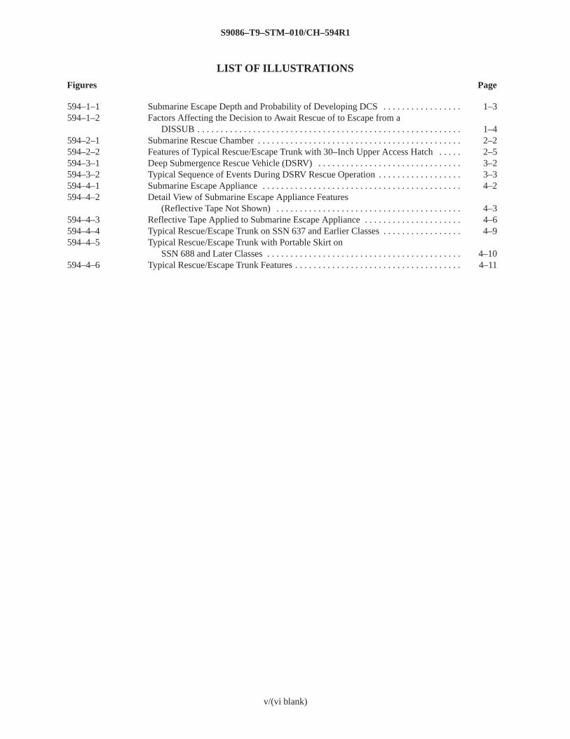
LIST OF ILLUSTRATIONS
Figures Page
S9086–T9–STM–010/CH–594R1
v
594–1–1 Submarine Escape Depth and Probability of Developing DCS 1–3. . . . . . . . . . . . . . . . . 594–1–2 Factors Affecting the Decision to Await Rescue of to Escape from a
DISSUB 1–4. . . . . . . . . . . . . . . . . . . . . . . . . . . . . . . . . . . . . . . . . . . . . . . . . . . . . . . . . 594–2–1 Submarine Rescue Chamber 2–2. . . . . . . . . . . . . . . . . . . . . . . . . . . . . . . . . . . . . . . . . . . . 594–2–2 Features of Typical Rescue/Escape Trunk with 30–Inch Upper Access Hatch 2–5. . . . . 594–3–1 Deep Submergence Rescue Vehicle (DSRV) 3–2. . . . . . . . . . . . . . . . . . . . . . . . . . . . . . . 594–3–2 Typical Sequence of Events During DSRV Rescue Operation 3–3. . . . . . . . . . . . . . . . . . 594–4–1 Submarine Escape Appliance 4–2. . . . . . . . . . . . . . . . . . . . . . . . . . . . . . . . . . . . . . . . . . . 594–4–2 Detail View of Submarine Escape Appliance Features
(Reflective Tape Not Shown) 4–3. . . . . . . . . . . . . . . . . . . . . . . . . . . . . . . . . . . . . . . . 594–4–3 Reflective Tape Applied to Submarine Escape Appliance 4–6. . . . . . . . . . . . . . . . . . . . . 594–4–4 Typical Rescue/Escape Trunk on SSN 637 and Earlier Classes 4–9. . . . . . . . . . . . . . . . . 594–4–5 Typical Rescue/Escape Trunk with Portable Skirt on
SSN 688 and Later Classes 4–10. . . . . . . . . . . . . . . . . . . . . . . . . . . . . . . . . . . . . . . . . . 594–4–6 Typical Rescue/Escape Trunk Features 4–11. . . . . . . . . . . . . . . . . . . . . . . . . . . . . . . . . . . .
v/(vi blank)
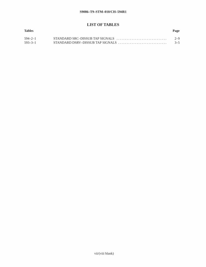
LIST OF TABLES
Tables Page
S9086–T9–STM–010/CH–594R1
vii
594–2–1 STANDARD SRC–DISSUB TAP SIGNALS 2–9. . . . . . . . . . . . . . . . . . . . . . . . . . . . . . 593–3–1 STANDARD DSRV–DISSUB TAP SIGNALS 3–5. . . . . . . . . . . . . . . . . . . . . . . . . . . . .
vii/(viii blank)
S9086–T9–STM–010/CH–594R1
1–1
CHAPTER 594SALVAGE – SUBMARINE SAFETY:ESCAPE AND RESCUE DEVICES
SECTION 1. SUBMARINE ABANDONMENT
594–1.1 CAUSES OF SUBMARINE ABANDONMENT
594–1.1.1 DESCRIPTION . Damage to a submarine resulting from an explosion, collision, material failure, orother event could lead to conditions that require abandoning the submarine while it is submerged. Whatever thecause, extensive flooding of major compartments may prevent the submarine from surfacing under its own power.Under such conditions, procedures for immediate rescue or escape must be initiated. If rescue or escape isdelayed, depleted oxygen levels in the submarine’s atmosphere and rising carbon dioxide levels can ultimatelylead to the death of the crew.
594–1.2 FACTORS INFLUENCING SUBMARINE ABANDONMENT
594–1.2.1 GENERAL . Most submarines have been fitted with at least two rescue/escape trunks, one for eachmain compartment. SSBN 726 class (TRIDENT) submarines have three rescue/escape trunks. These trunkstypically have all the features (see Section 4) necessary for either two–men escape evolutions using submarineescape appliances (Steinke hoods) or collective (group) rescues by a Deep Submergence Rescue Vehicle (DSRV)or a Submarine Rescue Chamber (SRC). The exterior hull structure around the upper access hatch of the rescue/escape trunks incorporates a strengthened, flat, machined seating surface (rescue seat) to allow for proper matingof a DSRV or SRC. For more information on the capabilities of and the requirements for using the DSRV or SRCrescue systems, see NAVSEA S9594–AE–GTP–010, Disabled Submarine Requirements for Employment ofU.S. Navy Submarine Rescue Systems.
594–1.2.2 RESCUE AND ESCAPE OPERATIONS. Listed below are general factors that influence how andwhen rescue and escape operations should be performed and how successful they will be. These factors have to beconsidered before deciding whether to abandon the submarine by using the rescue/escape trunks for individualescapes or to wait for collective rescue by a DSRV or SRC. Collective rescue by a DSRV or SRC is much saferthan individual escape and in most cases is the preferred method of submarine abandonment.
1. Time required for search and rescue forces to locate the disabled submarine (DISSUB). Survival timeaboard the DISSUB is limited. Early location of the DISSUB provides more time for the crew to assess thesituation and decide whether to await rescue or start escape operations.
2. Availability of a DSRV or SRC and its associated surface support. Surface support is essential in order tosafely and successfully conduct any submarine rescue operation. Depending on the location of the DISSUB andthe rate at which conditions in it are deteriorating, a DSRV or SRC might be unable to reach the accident sitebefore individual escape operations would have to begin.
S9086–T9–STM–010/CH–594R1
1–2
3. Depth of the DISSUB. Safe and successful escape operations using the submarine escape appliance arelimited by the depth of the DISSUB.
4. Pitch and roll angle of the submarine. The DSRV and SRC can only mate with the DISSUB within setpitch and roll limits.
5. Current across the submarine’s hull. The DSRV and SRC can only mate with the DISSUB within certaincurrent limits.
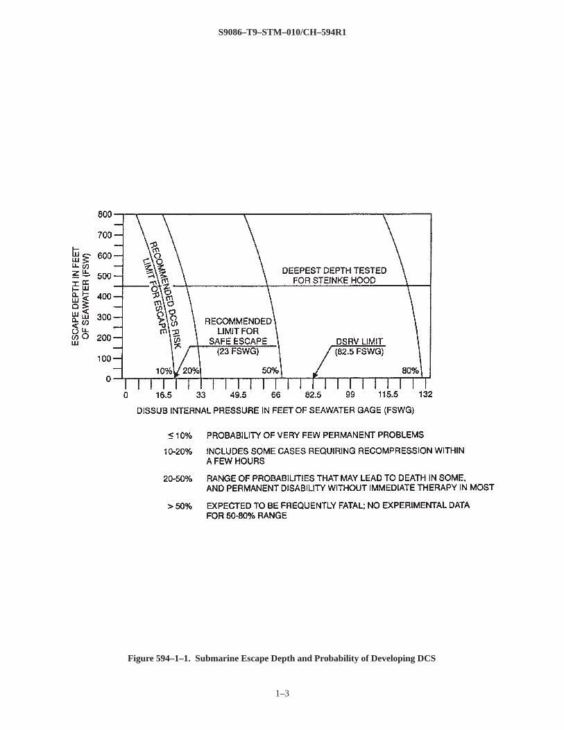
6. Internal pressure of the submarine. Pressurization of the DISSUB’s atmosphere affects the ability of theDSRV and SRC to mate with the DISSUB. Pressurization of the DISSUB’s atmosphere also increases the risk thatsurvivors will develop decompression sickness (DCS) upon returning to the surface (see Figure 594–1–1).
7. Temperature of the surrounding water. The temperature of the water and the temperature on the surfacewill affect the length of time that personnel, after escaping the DISSUB, can remain unprotected in the waterbefore developing hypothermia.
8. Weather conditions on the surface. Surface support capability, rescue operations, and the safe recovery ofescapees are affected by the weather conditions on the surface.
9. Condition of the submarine’s internal atmosphere. The concentrations of carbon dioxide, oxygen, andtoxic gases are major concerns that will influence the decision to escape or await rescue.
10. Extent of damage to the submarine. Flooding, fire, and extent of structural damage are key factors thatwill influence the decision to escape or await rescue.
594–1.2.3 RESCUE SYSTEM DEPLOYMENT. The following general factors should be taken into account bythe onsite Rescue Mission Commander when deciding which rescue system (DSRV or SRC) to deploy:
1. Location of the DISSUB.
2. Availability of a DSRV, SRC, and support ships.
3. Pitch and roll angle of the DISSUB.
4. Current across the DISSUB’s hull.
5. Weather conditions on the surface.
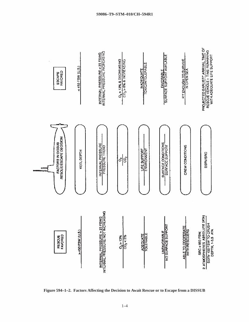
594–1.2.4 CRITERIA FOR ESCAPE OR RESCUE. Rescue, whenever feasible, is always preferred overescape from a medical and physiological point of view. There are conditions, however that require individuals toescape using Steinke hoods. Multiple factors must be considered when making the decision whether to escape orwait for rescue (see Figure 594–1–2). Of all these factors the greatest consideration should be given to theatmospheric conditions in the DISSUB, particularly the levels of carbon dioxide and oxygen in the air; the rate atwhich these levels are changing; and the DISSUB’s internal pressure.
594–1.2.4.1 Criteria Supporting the Decision to Escape. Escape should be considered if one or more of thefollowing criteria are met:
1. Uncontrolled flooding or fire exists.
2. The carbon dioxide concentration is approaching 6 percent and is continuing to increase after all meansto control carbon dioxide buildup have been used. Waiting until the carbon dioxide levels are intolerable will givesurvivors only a few extra hours to safely remain on board the DISSUB and will greatly complicate the escapesequence as the survivors’ mental capacities deteriorate.
3. The oxygen concentration is approaching 13 percent and is decreasing after using all onboard reserves.
S9086–T9–STM–010/CH–594R1
1–3
Figure 594–1–1. Submarine Escape Depth and Probability of Developing DCS
S9086–T9–STM–010/CH–594R1
1–4
Figure 594–1–2. Factors Affecting the Decision to Await Rescue or to Escape from a DISSUB
S9086–T9–STM–010/CH–594R1
1–5
4. The internal atmospheric pressure of the DISSUB is increasing and rescue is not immediatelyanticipated. Escape should be made before the internal pressure reaches 23 feet of seawater gage (fswg) or 1.7atmospheres to minimize the risk of DCS in survivors when they reach the surface. The DISSUB crew should useFigure 594–1–1 to determine when escape should begin based on the internal atmospheric pressure and the depthat which the rescue/escape trunk operations are to be conducted.
5. Persistent toxic atmosphere requires the use of emergency air breathing masks.
6. Surface support is present to retrieve and care for survivors, especially in colder waters.
7. Rescue/escape trunk operations are conducted at a depth of 450 feet of seawater (fsw) or less. Successfulescapes from greater depths are possible but are riskier.
8. The crew’s physical condition will allow them to survive in the open ocean until rescue personnel arrive.
594–1.2.4.2 Criteria Supporting the Decision to Await Rescue. The decision to await rescue should beconsidered if the following criteria are met:
1. Rescue assets are expected to arrive before conditions requiring escape develop.
2. Oxygen concentration is greater than 13 percent and carbon dioxide concentration is 3 percent or less andnot rapidly increasing.
3. Internal atmospheric pressure exceeds 23 fswg (1.7 atmospheres) and is not increasing.
4. Life support supplies such as carbon dioxide absorbent (lithium hydroxide) and oxygen are adequate tomaintain a breathable atmosphere until rescue.
5. Escape trunk operations would occur at a depth greater than 450 fsw.
6. There is no surface support for survivors and surface conditions are unfavorable (high winds, high seastate, or cold).
7. The crew is not physically fit or equipped to survive in the open sea for a long time.
594–1.2.5 COMMUNICATING THE SUBMARINE’S LOCATION . The submarine’s crew should use allavailable means to broadcast the status of the DISSUB. This will help locate the submarine and aid in making anearly decision about the rescue method to be used. The ship’s communication system or emergencycommunication transmitters can be used to signal that the submarine is disabled. Search and rescue ships candetect signals from various sources on the submarine, including active sonar equipment, underwater telephone,emergency underwater telephone, remote acoustic communication system (RACS), or the crew hammering on thehull. Search sonar on surface ships and side look sonar towed by surface ships can be used to locate thesubmarine. Flares, buoys, or debris ejected from the submarine that can be seen on the surface by aircraft orsurface ships can also indicate its location. During actual rescue operations, the AN/BQN–13 submarine distresspingers are the primary means of broadcasting the location of the DISSUB to search and rescue parties andguiding a DSRV to the submarine.
594–1.2.6 COMMUNICATING THE SUBMARINE’S CONDITION . Informing rescue personnel of thecondition of the DISSUB is vital. Knowledge of conditions in the submarine will aid rescue personnel indetermining what rescue methods to use and how to protect themselves during actual rescue operations. Thisinformation has also helped crews in the past during their escapes and is useful to salvage
S9086–T9–STM–010/CH–594R1
1–6
personnel during salvage operations. The following information should be recorded and transmitted to rescuepersonnel:
1. Location and extent of damage to the pressure hull, main ballast tanks, hull appendages, internalequipment, and ship systems.
2. Location and extent of flooding and the amount of nonflooded volume.
3. Condition of the atmosphere with regard to internal pressure, carbon dioxide and oxygen levels, presenceof contamination, etc.
4. Available services and equipment.
5. Availability of supplies such as carbon dioxide absorbent (lithium hydroxide), medical supplies, food,drinking water, etc.
6. Ship’s depth, pitch angle, roll angle, and true heading.
7. Number and general condition of survivors, including the extent of injuries.
8. Internal air temperature and temperature of seawater at DISSUB depth.
9. Number of Steinke hoods available.
10. Availability of air banks and current bank pressures, oxygen banks and current bank pressures, andatmospheric monitoring equipment.
S9086–T9–STM–010/CH–594R1
2–1
SECTION 2. COLLECTIVE RESCUE USING SUBMARINE RESCUE CHAMBER
594–2.1 SUBMARINE RESCUE CHAMBER (SRC)
594–2.1.1 GENERAL IDENTIFICATION . SRC’s are assigned to Commander Submarine DevelopmentSquadron Five as a primary part of the Submarine Rescue Fly–Away Kit. An SRC can be deployed on anyavailable ship with a crane capable of launching and recovering the SRC. The SRC’s rated depth is 259 meters(850 feet) with a test depth (no personnel on board) of 387 meters (1270 feet). The Submarine Rescue Fly–AwayKit is configured for aircraft load out and transportation to the nearest port facility. It contains all the equipmentrequired to lay a four–point moor and to support the SRC to a depth of 259 meters (850 feet). Under favorableconditions, the SRC can make a seal on a submarine that is inclined to angles up to 30 degrees from vertical ineither the fore and aft or athwartship’s direction.
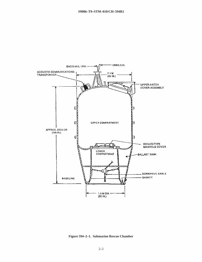
594–2.1.2 DESCRIPTION . The SRC design is based on the McCann chamber. The SRC is a cylindrical steelstructure with an elliptical head (see Figure 594–2–1). The SRC measures about 3.5 meters (11–1/2 feet) high andweighs approximately 9.52 metric tons (21,000 pounds). The outside diameter near the top measures 2.1 meters(84 inches) and tapers to 1.5 meters (60 inches) at the bottom. The SRC is divided into three sections: an uppercompartment, a lower compartment, and a ballast tank. The upper compartment houses all operating equipmentand controls, the operators, and rescued personnel. The lower compartment is open to ambient sea pressure exceptwhen seated on and sealed over a submarine rescue/escape hatch. On the bottom of the lower compartment is theSRC–to–disabled submarine (DISSUB) mating surface, which consists of a strengthened seating surface that has amachined dovetailed groove for a rubber sealing gasket. This rubber gasket is held in place by a stainless steelretaining ring. The SRC is supported by a surface ship during all operations. Air, electrical power, andcommunications are provided to the SRC through an umbilical between the support ship and the SRC. For adetailed description of the SRC, detailed operating procedures, and maintenance instructions, refer to NAVSEASS750–AA–MMA–010/850 FT, Technical Manual for Modernized 850 Foot Submarine Rescue Chambers.The following sections briefly discuss some of the various features and systems of the SRC.
594–2.1.3 EXTERIOR FEATURES . On the outside and top of the SRC are hull penetrations with watertightfittings for an air supply hose, an air exhaust hose, a communications cable, and an electrical power cable. A25–inch, handwheel–operated, hinged, three–dog access hatch surrounded by a raised coaming permits entrancefrom the top of the SRC into the upper compartment. An oval–shaped, pressureproof, boiler–type manhole coverheld in place with a strongback separates the upper and lower compartments. This manhole cover permits entranceinto the lower compartment from the upper compartment after a seal has been achieved between the SRC and theDISSUB and pressure has been equalized between the upper and lower compartments.
594–2.1.4 UPPER COMPARTMENT . The upper compartment contains all the equipment and controls neededto operate the SRC. The compartment has
S9086–T9–STM–010/CH–594R1
2–2
Figure 594–2–1. Submarine Rescue Chamber
S9086–T9–STM–010/CH–594R1
2–3
room for two operators and six rescued personnel. During rescue operations, this compartment can be maintainedat atmospheric pressure by periodic manual venting to the surface, or the upper compartment can be pressurized.Various support tools and equipment are also stored in the upper compartment.
594–2.1.4.1 Air Motor . An air–driven, reversible motor, located in the upper compartment, is connected to adownhaul cable reel in the lower compartment by a drive train assembly that penetrates the two compartmentsthrough a watertight stuffing box. SRC operators can regulate air pressure to the motor to control ascent anddescent of the SRC.
594–2.1.4.2 Ballast. Two types of ballast, fixed and variable, are carried in the upper compartment of the SRC.The SRC is normally ballasted with fixed lead or zinc ballast to 454 kilograms (1000 pounds) positive buoyancywith the ballast tank dry, the lower compartment full of water, a full load of variable ballast on board, and twooperators in the upper compartment. Variable ballast is used to make up for the weight of the rescued personnel.The variable ballast, in the form of 544.3 kilograms (1200 pounds) of water, is stored in 12 cans or ballast bags inthe SRC. After the SRC mates with the submarine and the rescued personnel are brought on board, the variableballast is drained into the submarine. The empty ballast cans or bags are kept in the SRC. The variable ballast isreplenished after each ascent.
594–2.1.4.3 Instrumentation . Various pressure gauges are located in the upper compartment. The uppercompartment pressure gauge (caisson gauge) displays the air pressure in the upper compartment. The sea pressuregauge indicates the sea pressure and depth of the SRC. Other gauges are used to monitor the following: air supplypressure to the SRC, air motor supply pressure, lower compartment pressure, ballast tank pressure, emergencybreathing system air pressure, and hydraulic cable cutter pressure.
594–2.1.4.4 Electrical Equipment. The SRC receives 120–volt, 60–cycle electrical power from the surfacesupport ship with an overcurrent protection device rated at 25 amps. The 396–meter (1300–feet) long power cableconnects to a MIL–C–24231 type electrical hull insert on top of the SRC to supply a four–circuit fuseddistribution panel in the upper compartment. The distribution panel controls two lights in the upper compartment,a receptacle, and two 250–watt pressureproof quartz halogen light fixtures in the lower compartment.
594–2.1.4.5 Communication Equipment. There are three ways to communicate with the SRC: the divers’speaker system, a sound–powered telephone, and an underwater telephone system. The underwater telephone isthe primary means of communication between the SRC and the DISSUB.
594–2.1.4.6 Viewports. Two acrylic viewports equipped with protective covers are installed in the hull of theupper compartment for viewing the lower compartment and the downhaul cable and reel.
594–2.1.5 LOWER COMPARTMENT . The lower compartment contains the downhaul equipment and twopressureproof lights. It also provides access to the DISSUB.
594–2.1.5.1 Downhaul Equipment. The downhaul equipment is used to winch the SRC down to the DISSUBand to control the ascent back to the surface. The
S9086–T9–STM–010/CH–594R1
2–4
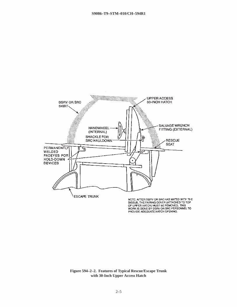
equipment consists of an air motor and drive train assembly located in the upper compartment; a downhaulmechanism made up of a gearbox, cable drum, spooling device, and a fairlead assembly; a hydraulic cable cutteroperated by a handpump in the upper compartment; and an air motor lubrication system. The downhaul cable is agalvanized steel wire rope. This cable is 396 meters (1300 feet) long, and 11 millimeters (7/16 inch) in diameter.One end is secured to and wound around the cable reel. The other end has a swivel end fitting and a safety hook.During rescue operations, the safety hook is coupled to a shackle located near the center of the submarine’srescue/escape trunk upper access hatch (see Figure 594–2–2). The downhaul cable is attached by air or mixed gasdivers (for shallow depths), saturation divers (for shallow depths), a Remotely Operated Vehicle (ROV) with amanipulator arm, a Deep Submergence Vehicle (DSV), or an Atmospheric Diving System (ADS) for deeperdepths.
594–2.1.5.2 Hold–Down Devices. Four hold–down devices, stored in the upper compartment, are used to holdthe SRC securely to the rescue seat after a seal is made between the SRC and the DISSUB. These devices fit intobeveled slots in a reinforced circular ring welded around the inside circumference of the lower compartment. Theshackle or jaw end on the lower part of each device is secured to one of four attachment points located around theperimeter of the submarine’s upper access hatch. Three types of attachment points are used. One type is apermanently welded staple that is typically used on SSN 637 and earlier classes of submarines that have25–inch–diameter upper access hatches. On these submarines, the staples are normally attached to the outer hull.Another type of attachment point used is a permanently welded padeye (see Figure 594–2–2). SSN 688, SSBN726, and SSN 21 class submarines have 30–inch–diameter upper access hatches with the padeyes installed belowthe level of the hatch fairing cover. To access these padeyes, the hatch fairing cover must be removed. Thesepadeyes are being replaced with a threaded eyebolt referred to as a Portsmouth interlock. The threaded eyebolt iscarried on the rescue vehicle and is installed by the SRC crew after a seal is made with the DISSUB. The eyeboltsare installed into special threaded receivers that are welded into the submarine’s structure, flush with the rescueseat. The eyebolt and receiver has three advantages over the welded padeyes:
1. It allows the rescue crew to install hold–down devices before removing the hatch fairing cover. On SSN688, SSBN 726, and SSN 21 class submarines, which have the permanently welded type of padeyes, the hatchfairing covers must be removed to access the padeyes and to allow the 30–inch–diameter hatch to be opened to themaximum extent within the SRC skirt.
2. It is significantly stronger than the welded padeyes or staples.
3. It allows for increased submarine hatch opening angles within the rescue vehicle skirt for easier accessbetween the submarine and the rescue vehicle.
594–2.1.6 BALLAST TANK . The ballast tank surrounds the lower compartment and can change the buoyancy ofthe SRC by approximately 1360 kilograms (3000 pounds). It is usually dry and kept at atmospheric pressureexcept when a seal is being made with a submarine. Removing the ten inspection covers that surround the ballasttank allows access to perform inspection and maintenance.
594–2.1.7 PIPING SYSTEMS. The SRC has several piping systems that allow it to work properly.
S9086–T9–STM–010/CH–594R1
2–5
Figure 594–2–2. Features of Typical Rescue/Escape Trunkwith 30-Inch Upper Access Hatch
S9086–T9–STM–010/CH–594R1
2–6
594–2.1.7.1 Air System. The air system provides air from the support ship for the crew to breathe. The airsupplied is also used to operate the downhaul air motor, blow the ballast tank and the lower compartment, transferwater, and supply the emergency breathing system.
594–2.1.7.2 Flood and Drain System. The flood and drain system controls the flooding and draining of theballast tank and the lower compartment. This system allows water to be directed into the ballast tank or lowercompartment, transferred from one to the other, or blown to sea. The buoyancy of the SRC changes by about 1360kilograms (3000 pounds) when the lower compartment is flooded or blown dry.
594–2.1.7.3 Spill and Vent System. The spill and vent system provides the ability to completely vent or drain theballast tank when the SRC is seated at an angle on the submarine. The spill and vent system also provides thecapability to flood and drain the ballast tank in an emergency.
594–2.1.7.4 Hydraulic System. A hydraulic system is used to operate the downhaul wire cable cutter in thelower compartment. It consists of a handpump and associated piping, valves, and pressure gauge. Should thedownhaul cable become fouled, preventing the SRC from ascending or descending, the cable can be cut by theSRC operators. This will allow the SRC to float to the surface.
594–2.1.7.5 Emergency Breathing System. The emergency breathing system provides air for the SRC occupantsto breathe if the SRC atmosphere becomes contaminated or the DISSUB atmosphere is toxic. The system consistsof eight breathing masks with demand flow regulators and two manifolds.
594–2.1.7.6 Exhaust and Vent System. The exhaust and vent system allows the ballast tank and lowercompartment to be vented, removes the air motor exhaust, and ventilates the upper compartment to the surface.
594–2.1.8 MISCELLANEOUS EQUIPMENT . The following equipment is required for proper operation ofeach SRC.
594–2.1.8.1 Hoses. Air is supplied to the SRC from the support ship through a wire–reinforced air supply hosewith a 25–millimeter (1–inch) inside diameter. Air is vented to the surface through a wire–reinforced exhaust hosewith 32–millimeter (1–1/4 inch) inside diameter. The hoses come in 15–meter (50–foot) lengths and are coupledtogether to form assemblies 396 meters (1300 feet) long.
594–2.1.8.2 Communication Cable. The communication cable consists of a cable 396 meters (1300 feet) longmade of DLT special diving telephone and lifeline cable or its replacement, TSS–4 cable.
594–2.1.8.3 Backhaul Line. The backhaul line is a synthetic fiber rope with a minimum breaking strength of596,032 newtons (134,000 pounds) and a length of 396 meters (1300 feet). The backhaul line is attached to alifting eye welded to the top of the SRC. The backhaul line is used to tend the SRC from the surface and foremergency recovery; it is not used to lift the SRC from or onto the deck of the support ship. During SRC descentand ascent, the backhaul line stays slack to avoid overstressing the downhaul cable.
594–2.1.8.4 Lifting Pendant. The lifting pendant is a galvanized steel wire rope 0.9 meter (3 feet) long and
S9086–T9–STM–010/CH–594R1
2–7
32 millimeters (1–1/4 inches) in diameter. It has a poured zinc socket, ring, and safety shackle assembly. Thelifting pendant is used to handle the SRC during transfer from and to the support ship. The length of the pendantused depends on the requirements of the support ship.
594–2.1.8.5 Miscellaneous Tool Bag. A bag of mission–essential tools is stored in the SRC. These tools arerequired for emergency repairs and adjustments, and, when necessary, for removing and handling the fairing coverfrom over the submarine’s upper access hatch.
594–2.1.8.6 Battle Lanterns. Four portable battle lanterns for emergency lighting are mounted in the SRC.
594–2.1.8.7 Lower Hatch Lifting Tackle . The lower hatch lifting tackle consists of 38 meters (125 feet) of16–millimeter–diameter (5/8–inch) polyester line; a double–sheave luff tackle; and a single–sheave,102–millimeter (4–inch) lifting block. The double–sheave luff tackle is secured to a padeye in the overhead of theupper compartment. The hatch lifting tackle is used for handling the submarine fairing cover pieces and fairingcover compensation weight, when necessary, and the SRC lower hatch. The lifting tackle is also used to helpremove injured personnel from the submarine.
594–2.1.8.8 Protective Headgear. Eight sets of protective headgear, which should be worn at all times, arestored in the upper compartment for use by the SRC crew and rescued personnel.
594–2.2 SRC RESCUE OPERATIONS
594–2.2.1 GENERAL . The following section provides a general outline of the sequence of events that occurswhen the SRC is used to perform a collective rescue. Before starting the rescue, the DISSUB crew should notifythe rescue forces of the condition of the submarine as described in paragraph 594–1.2.6, prepare the rescue/escapetrunk as described in the applicable ship system manual, and organize into groups of six to facilitate an orderlyrescue. Refer to the applicable ship system manual and to NAVSEA SS750–AA–MMA–010/850 FT for detailedprocedures to be followed by the submarine crew and the SRC operators during rescue operations.
1. After locating the DISSUB, the support ship establishes a four–point mooring with the center as near aspossible over the DISSUB. The ship then moves up current of the submarine about 15 to 30 meters (50 to 100feet).
2. A downhaul cable is connected to the shackle on the upper access hatch of the rescue/escape trunkdesignated to be used during the rescue operation. The submarine crew prepares the trunk in accordance with theapplicable ship system manual.
3. The air supply hose is connected to air flasks on the support ship and to the proper fitting on the SRC.The air exhaust hose is secured with one end open to the atmosphere on board the support ship and the other endsecured to the proper fitting on the SRC. The communication cable is connected to the SRC fitting and is pluggedinto the communication system’s receptacle on the support ship. The power cable is plugged into the supportship’s electrical circuit and the other end is secured to the proper fitting on the SRC. The air lines, power cable,and communications cable are bound together to a 76–millimeter–diameter (3–inch) nylon rope strength member.This assembly is referred to as the umbilical. To allow the SRC to operate freely, the umbilical is kept slackduring the descent and ascent.
S9086–T9–STM–010/CH–594R1
2–8
After all service connections from the support ship to the SRC are tested, the SRC is lowered over the side of thesupport ship. Pressure in the air supply line is kept at least 345 kiloPascals (kPa) (50 pound–force per square inchgage [psig]) higher than the ambient sea pressure or 1379 kPa (200 psig), whichever is greater.
4. When the SRC is ready for the descent, the operators board it through the upper hatch. After the upperhatch is closed and the lower compartment is flooded, the SRC descends to the DISSUB.
5. In shallow water (less than 61 meters [200 feet]) a seal is made between the SRC and the submarine byflooding the ballast tank, taking up the slack in the downhaul cable, blowing the lower compartment, and thenventing the lower compartment to topside. This method of forming a seal can also be used at greater depths if thecurrent or rescue seat conditions on the submarine will not allow a seal to be formed as described below.
6. The seal caused by sea pressure is enough to hold the SRC tightly against the rescue seat. This type ofseal is made by rapidly transferring water from the lower compartment to the ballast tank. The SRC is intended foruse in rescue operations in which the pressure within the DISSUB is at or near atmospheric pressure. Allpressurized rescue operations should follow current diving practices and safety precautions to ensure that anyrequired decompression is done properly.
7. After a seal is made and the SRC lower chamber is drained, the SRC crew instructs the submarine todrain the upper hatch cavity to equalize pressure between the submarine and the SRC (see Table 594–2–1 forstandard tap signals used between the SRC and DISSUB). The submarine crew then drains the trunk, if necessary.The pressure in the trunk and the access compartment should be the same before the lower access hatch to thetrunk is opened.
8. On submarines that have been modified to use the threaded eyebolt, the SRC crew installs them. TheSRC crew installs the hold–down devices and removes the downhaul cable and fairlead assembly. They thenremove the submarine hatch fairing. Next, the SRC crew installs a compensating weight onto the hatch or, on SSN21 class submarines, unscrews a spring retainer screw to compensate for the removal of the fairing.
9. On submarines with permanently welded padeyes or staples, the SRC crew removes the submarine hatchfairing, if necessary. On earlier classes of submarines with 25–inch–diameter upper access hatches, the fairings arenot removed. The SRC crew installs the hold–down devices and removes the downhaul cable and fairleadassembly. The SRC crew then installs a compensating weight onto the hatch or, on SSN 21 class submarines,unscrews a spring retainer screw to compensate for the removal of the fairing.
10. The SRC crew directs the submarine’s crew to open the upper access hatch and then the lower accesshatch.
11. The fairing plates, if removed, and supplies as needed are transferred to the submarine. These suppliescan include oxygen, lithium hydroxide canisters, water, food, clothes, medical supplies, etc.
12. Submarine personnel are brought aboard the SRC. The variable ballast is transferred to the submarine tomake up for the submarine personnel brought on board the SRC. After the ballast is transferred to the submarine,the submarine crew is directed to close the upper access hatch and the hatch cavity drain valve, the trunk floodvalve, and the trunk drain valve.
13. The SRC crew installs the fairlead assembly, attaches the downhaul cable to the hatch, removes thehold–down devices, and installs the boiler–type manhole cover between the upper and lower compartments. TheSRC detaches from the DISSUB and returns to the surface.
S9086–T9–STM–010/CH–594R1
2–9
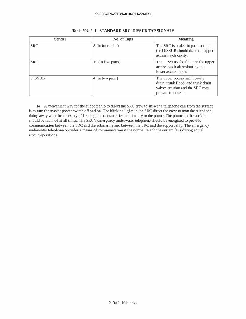
Table 594–2–1. STANDARD SRC–DISSUB TAP SIGNALS
Sender No. of Taps Meaning
SRC 8 (in four pairs) The SRC is sealed in position andthe DISSUB should drain the upperaccess hatch cavity.
SRC 10 (in five pairs) The DISSUB should open the upperaccess hatch after shutting thelower access hatch.
DISSUB 4 (in two pairs) The upper access hatch cavitydrain, trunk flood, and trunk drainvalves are shut and the SRC mayprepare to unseal.
14. A convenient way for the support ship to direct the SRC crew to answer a telephone call from the surfaceis to turn the master power switch off and on. The blinking lights in the SRC direct the crew to man the telephone,doing away with the necessity of keeping one operator tied continually to the phone. The phone on the surfaceshould be manned at all times. The SRC’s emergency underwater telephone should be energized to providecommunication between the SRC and the submarine and between the SRC and the support ship. The emergencyunderwater telephone provides a means of communication if the normal telephone system fails during actualrescue operations.
2–9/(2–10 blank)
S9086–T9–STM–010/CH–594R1
3–1
SECTION 3. COLLECTIVE RESCUE USING DEEP SUBMERGENCE RESCUE VEHICLE
594–3.1 DEEP SUBMERGENCE RESCUE VEHICLE (DSRV)
594–3.1.1 GENERAL . There are two DSRV’s: DSRV–1 (Mystic) and DSRV–2 (Avalon). The primary mission ofthe DSRV is to provide a quick reaction, worldwide, all–weather capability to rescue personnel from disabledsubmarines (DISSUB) at depths of less than 610 meters (2000 feet). The DSRV’s maximum operating depth isapproximately 1524 meters (5000 feet). The DSRV can be transported by truck, aircraft, surface ship, or on amother submarine. The DSRV can dive, locate the DISSUB, and attach itself to the DISSUB’s rescue seat. Afterthe DSRV is properly attached to the submarine, the DISSUB’s access hatches are opened and submarinepersonnel can enter directly into the DSRV. The DSRV then detaches itself from the submarine and transfers therescued personnel to the support ship, which can be a specially modified submarine or a surface ship. For a moredetailed description of the DSRV system, refer to NAVSEA 0905–LP–120–0010, Technical Manual for DSRVSystem.
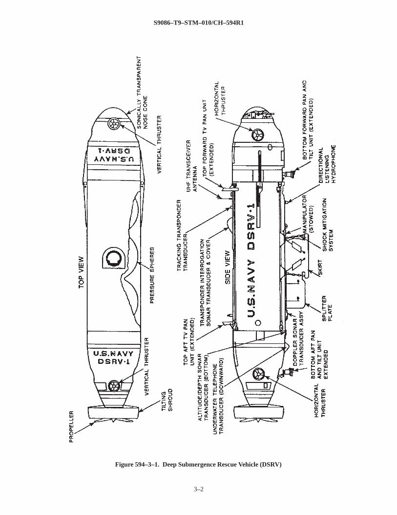
594–3.1.2 DESCRIPTION . The DSRV outer hull is approximately 15 meters (50 feet) long, 2.4 meters (8 feet)in diameter, and is constructed of formed fiberglass (see Figure 594–3–1). The DSRV weighs approximately 36metric tons (80,000 pounds). Inside the fiberglass outer hull are three interconnected spheres that form thepressure hull. Each sphere is 2.3 meters (7–1/2 feet) in diameter and is constructed of high tensile strength steel.The spheres are connected by hatches that allow personnel to move within the DSRV. The forward sphere containsthe vehicle’s sophisticated control and navigation equipment and is manned by an operator and a co–operator. Thecenter and after spheres accommodate up to 24 passengers and two DSRV crewman.
594–3.1.3 DSRV SKIRT. Under the DSRV’s center sphere is a hemispherical skirt and shock mitigation systemthat allows the DSRV to mate with the rescue seat on the submarine’s rescue/escape trunk (see Figure 594–2–2).The skirt allows a watertight seal to be made between the DSRV and the submarine. After a seal is made, thesubmarine’s upper access hatch can be opened and swung up into the skirt cavity.
594–3.1.4 DSRV PROPULSION AND CONTROL. Propulsion and control of the DSRV is provided by aconventional, battery–powered, stern propeller in a movable shroud; and four ducted thrusters, two forward andtwo aft. The system permits the DSRV to maneuver and hover in underwater currents. The DSRV can attach to asubmarine inclined to angles up to 45 degrees from vertical in either the fore and aft or athwartships direction,with an internal pressure of up to 3–1/2 atmospheres, and exposed to a current of up to 2 knots.
594–3.2 DSRV RESCUE OPERATIONS
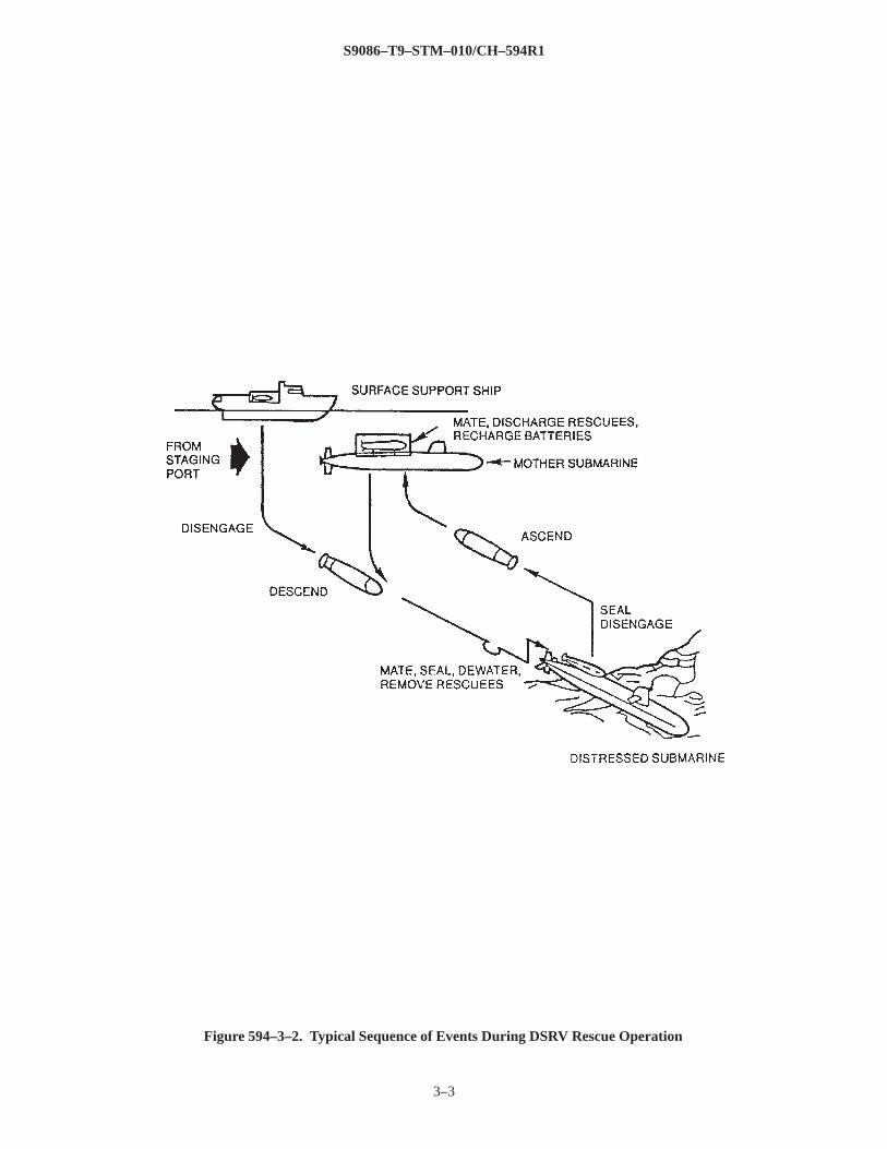
594–3.2.1 GENERAL . The following section provides a general outline of the sequence of events that occurswhen the DSRV is used to perform a collective rescue (see Figure 594–3–2). Before starting the rescue, theDISSUB crew should notify the rescue forces of the condition of the submarine as described in paragraph594–1.2.6, prepare the rescue/escape trunk as described in the applicable ship system
S9086–T9–STM–010/CH–594R1
3–2
Figure 594–3–1. Deep Submergence Rescue Vehicle (DSRV)
S9086–T9–STM–010/CH–594R1
3–3
Figure 594–3–2. Typical Sequence of Events During DSRV Rescue Operation
S9086–T9–STM–010/CH–594R1
3–4
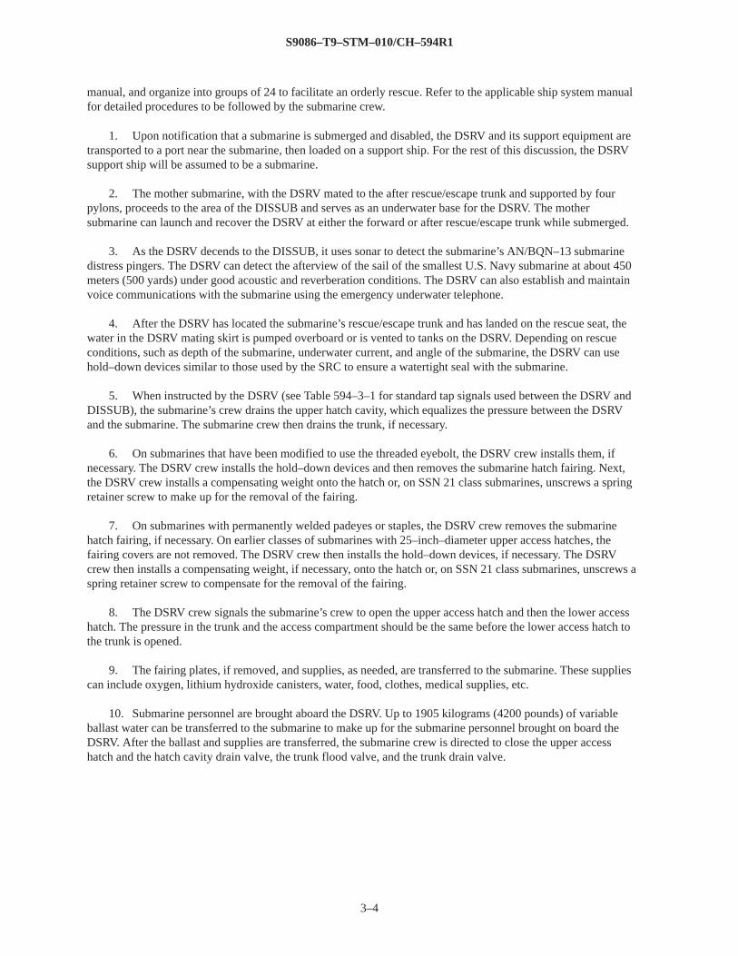
manual, and organize into groups of 24 to facilitate an orderly rescue. Refer to the applicable ship system manualfor detailed procedures to be followed by the submarine crew.
1. Upon notification that a submarine is submerged and disabled, the DSRV and its support equipment aretransported to a port near the submarine, then loaded on a support ship. For the rest of this discussion, the DSRVsupport ship will be assumed to be a submarine.
2. The mother submarine, with the DSRV mated to the after rescue/escape trunk and supported by fourpylons, proceeds to the area of the DISSUB and serves as an underwater base for the DSRV. The mothersubmarine can launch and recover the DSRV at either the forward or after rescue/escape trunk while submerged.
3. As the DSRV decends to the DISSUB, it uses sonar to detect the submarine’s AN/BQN–13 submarinedistress pingers. The DSRV can detect the afterview of the sail of the smallest U.S. Navy submarine at about 450meters (500 yards) under good acoustic and reverberation conditions. The DSRV can also establish and maintainvoice communications with the submarine using the emergency underwater telephone.
4. After the DSRV has located the submarine’s rescue/escape trunk and has landed on the rescue seat, thewater in the DSRV mating skirt is pumped overboard or is vented to tanks on the DSRV. Depending on rescueconditions, such as depth of the submarine, underwater current, and angle of the submarine, the DSRV can usehold–down devices similar to those used by the SRC to ensure a watertight seal with the submarine.
5. When instructed by the DSRV (see Table 594–3–1 for standard tap signals used between the DSRV andDISSUB), the submarine’s crew drains the upper hatch cavity, which equalizes the pressure between the DSRVand the submarine. The submarine crew then drains the trunk, if necessary.
6. On submarines that have been modified to use the threaded eyebolt, the DSRV crew installs them, ifnecessary. The DSRV crew installs the hold–down devices and then removes the submarine hatch fairing. Next,the DSRV crew installs a compensating weight onto the hatch or, on SSN 21 class submarines, unscrews a springretainer screw to make up for the removal of the fairing.
7. On submarines with permanently welded padeyes or staples, the DSRV crew removes the submarinehatch fairing, if necessary. On earlier classes of submarines with 25–inch–diameter upper access hatches, thefairing covers are not removed. The DSRV crew then installs the hold–down devices, if necessary. The DSRVcrew then installs a compensating weight, if necessary, onto the hatch or, on SSN 21 class submarines, unscrews aspring retainer screw to compensate for the removal of the fairing.
8. The DSRV crew signals the submarine’s crew to open the upper access hatch and then the lower accesshatch. The pressure in the trunk and the access compartment should be the same before the lower access hatch tothe trunk is opened.
9. The fairing plates, if removed, and supplies, as needed, are transferred to the submarine. These suppliescan include oxygen, lithium hydroxide canisters, water, food, clothes, medical supplies, etc.
10. Submarine personnel are brought aboard the DSRV. Up to 1905 kilograms (4200 pounds) of variableballast water can be transferred to the submarine to make up for the submarine personnel brought on board theDSRV. After the ballast and supplies are transferred, the submarine crew is directed to close the upper accesshatch and the hatch cavity drain valve, the trunk flood valve, and the trunk drain valve.
S9086–T9–STM–010/CH–594R1
3–5
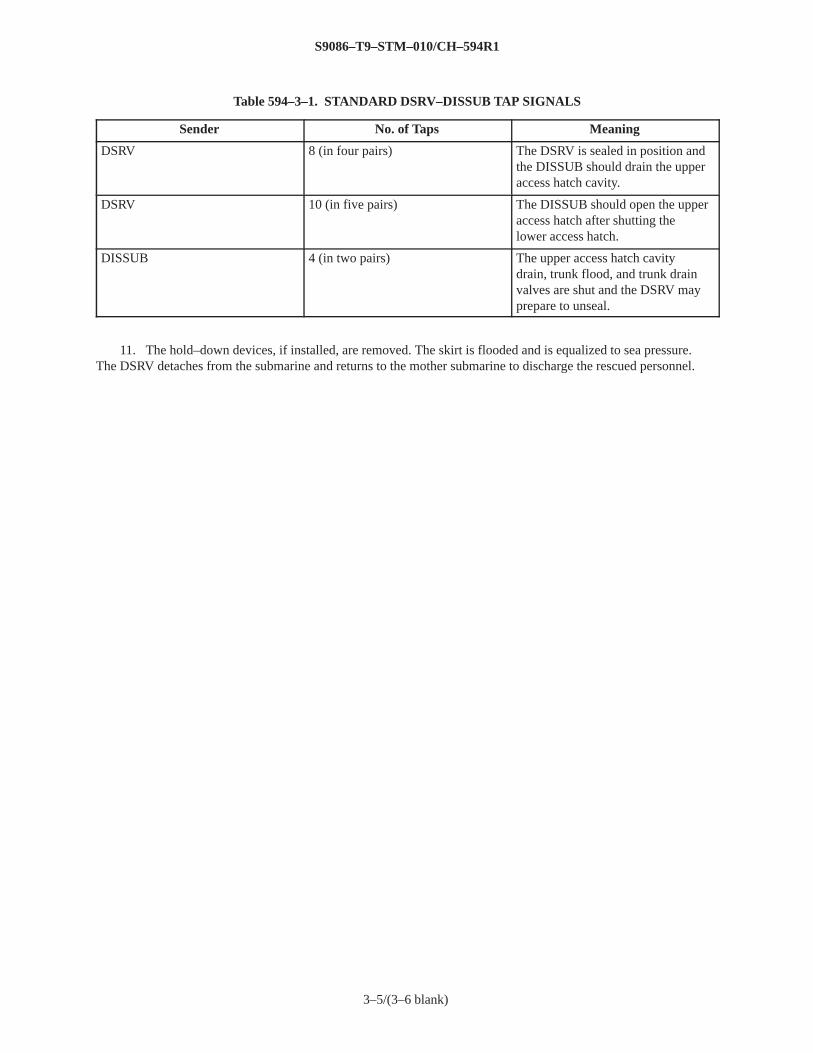
Table 594–3–1. STANDARD DSRV–DISSUB TAP SIGNALS
Sender No. of Taps Meaning
DSRV 8 (in four pairs) The DSRV is sealed in position andthe DISSUB should drain the upperaccess hatch cavity.
DSRV 10 (in five pairs) The DISSUB should open the upperaccess hatch after shutting thelower access hatch.
DISSUB 4 (in two pairs) The upper access hatch cavitydrain, trunk flood, and trunk drainvalves are shut and the DSRV mayprepare to unseal.
11. The hold–down devices, if installed, are removed. The skirt is flooded and is equalized to sea pressure.The DSRV detaches from the submarine and returns to the mother submarine to discharge the rescued personnel.
3–5/(3–6 blank)
S9086–T9–STM–010/CH–594R1
4–1
SECTION 4. INDIVIDUAL ESCAPE USING THE RESCUE/ESCAPE TRUNK
594–4.1 INDIVIDUAL ESCAPE
594–4.1.1 DEFINITION . Individual escape is defined as individual abandonment of the submarine by buoyantascent through the water to the surface with the use of a submarine escape appliance (Steinke hood). This kind ofescape can be made without assistance from a Deep Submergence Rescue Vehicle (DSRV) or a Submarine RescueChamber (SRC).
594–4.1.2 METHOD . This buoyant, free–breathing escape method is a relatively safe and rapid way to makeindividual escapes from a sunken submarine up to depths of 137 meters (450 feet). This method has been usedsuccessfully in open sea ascents from a depth of approximately 97 meters (318 feet) and in simulated ascents froma depth of approximately 137 meters (450 feet). Escape from depths as great as approximately 183 meters (600feet) is physiologically feasible but poses a greater risk of injury to survivors (see Figure 594–1–1).
594–4.2 SUBMARINE ESCAPE APPLIANCE
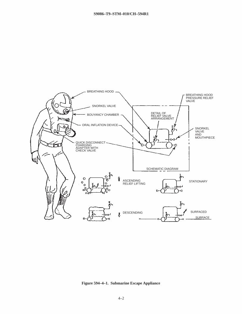
594–4.2.1 GENERAL . The submarine escape appliance is also known as the Steinke hood (shown inFigure 594–4–1). It is used by submarine personnel and is designed to get them to the surface with a supply ofbreathable air. The appliance conforms to the requirements of MIL–E–23155, Escape Appliance, Hooded, AirInflatable, with Pouch, Submarine Personnel. Once on the surface, the appliance acts as a life preserver. Theappliance’s buoyancy chamber is inflated with breathable compressed air from connections in the submarine’srescue/escape trunk. The appliance can also be inflated using an oral inflation device attached on the front of it.The appliance is usually inflated orally only when testing its operation before entering the rescue/escape trunk orwhen using it as a life preserver on the surface.
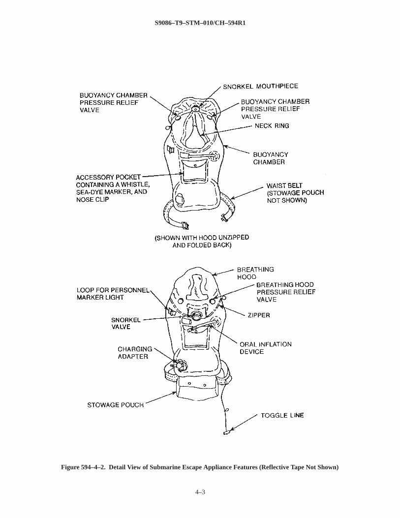
594–4.2.2 DESCRIPTION . The submarine escape appliance consists of the following items as shown inFigure 594–4–2:
1. Buoyancy chamber2. Breathing hood3. Neck ring4. Oral inflation device5. Snorkel valve and mouthpiece6. Charging adapter with check valve7. Two pressure relief valves on the buoyancy chamber8. Two pressure relief valves on the breathing hood9. Zipper10. Accessory pocket containing a whistle, sea–dye marker, and nose clip11. Belt12. Toggle line13. Preserver stowage pouch14. Personnel marker light15. Reflective tape
The orange fabric breathing hood is attached to the orange buoyancy chamber. The buoyancy chamber has aconnection that allows the chamber to be charged with compressed air through a charging manifold in the rescue/escape trunk.
S9086–T9–STM–010/CH–594R1
4–2
Figure 594–4–1. Submarine Escape Appliance
BREATHING HOOD
SNORKEL VALVE
BOUYANCY CHAMBER
ORAL INFLATION DEVICE
QUICK DISCONNECTCHARGINGADAPTER WITHCHECK VALVE
ASCENDINGRELIEF LIFTING
DESCENDING
STATIONARY
SURFACED
SURFACE
SCHEMATIC DIAGRAM
SNORKELVALVEANDMOUTHPIECE
BREATHING HOODPRESSURE RELIEFVALVE
DETAIL OFRELIEF VALVEARRANGEMENT
S9086–T9–STM–010/CH–594R1
4–3
Figure 594–4–2. Detail View of Submarine Escape Appliance Features (Reflective Tape Not Shown)
S9086–T9–STM–010/CH–594R1
4–4
During ascent to the surface, expanding air from within the buoyancy chamber passes through two relief valvesand into the hood to ventilate it and keep it expanded. The escapee, with his head in the hood, has enough airavailable to breathe normally.
594–4.2.2.1 Buoyancy Chamber. The buoyancy chamber is made of orange, neoprene–coated, nylon fabric. Thechamber is constructed so that it forms a collar that allows the wearer to pass his head through it during use. Wheninflated, the buoyancy chamber provides the positive buoyancy necessary for ascent to the surface. While on thesurface, the chamber provides the escapee with approximately 14 kilograms (30 pounds) of additional positivebuoyancy. During ascent to the surface, air in the pressurized chamber expands and passes through two reliefvalves on the top of the chamber. This air passes into the breathing hood and supplies breathable air to theescapee.
594–4.2.2.2 Breathing Hood. A fabric hood is attached to the collar portion of the buoyancy chamber. A clear,T–shaped plastic face shield in the hood provides visibility.
594–4.2.2.3 Neck Ring. A neck ring made of neoprene–coated nylon stretch cloth is connected to the base of thecollar. The neck ring prevents air from escaping from around the escapee’s neck and out of the breathing hoodduring ascent.
594–4.2.2.4 Oral Inflation Device. An oral inflation device consisting of a tube and an oral inflation check valveis installed on the front of the buoyancy chamber. The valve can be secured in the closed position by rotating aknurled ring counterclockwise toward the mouthpiece on the valve. This prevents accidental opening of the valve,which could deflate the buoyancy chamber.
594–4.2.2.5 Snorkel Valve and Mouthpiece. A plastic snorkel valve with an attached neoprene mouthpiece inthe breathing hood allows the escapee to breathe outside air while wearing the hood. When the valve is rotated tothe OPEN position, the escapee can breathe outside air using the mouthpiece. When the valve is rotated to theCLOSED position, no air can pass through the mouthpiece.
594–4.2.2.6 Charging Adapter and Check Valve. A charging adapter and check valve are installed on the lowerpart of the appliance. The charging adapter is used with quick disconnect hose couplings on the escape applianceair charging manifold in the rescue/escape trunk. The check valve prevents air from escaping from the buoyancychamber after the appliance is charged with compressed air and the charging hose is disconnected from the escapeappliance.
594–4.2.2.7 Buoyancy Chamber Pressure Relief Valves. Two pressure relief valves are installed on top of thebuoyancy chamber under the breathing hood on either side of the appliance. The valves are exposed to thedifference in pressure between the buoyancy chamber and the interior of the breathing hood. During ascent to thesurface, the valves automatically open to allow air expanding in the buoyancy chamber to vent into the hood. Thevalves have the following fixed open and reseat values: open at 12.1 kiloPascals (kPa) (1.75 pound–force persquare inch gage [psig]) maximum and closed at 10.3 kPa (1.5 psig) minimum. The valves have a flow capacity of0.16 cubic meter (5.5 cubic feet) per minute at a differential pressure of 20.7 kPa (3.0 psig).
594–4.2.2.8 Breathing Hood Pressure Relief Valves. Two pressure relief valves are located on the sides of the
S9086–T9–STM–010/CH–594R1
4–5
breathing hood. The valves are exposed to the difference in pressure between the inside of the hood and thesurrounding seawater. The valves regulate the air pressure in the hood during ascent to the surface.
594–4.2.2.9 Zipper. A zipper is installed on the base of the hood and attaches it to the collar of the buoyancychamber. The zipper allows enough of the hood to be detached from the buoyancy chamber so that the escapeecan throw it behind his head when on the surface. A protective flap is provided on top of the zipper to keep it fromchafing the escapee’s neck.
594–4.2.2.10 Accessory Pocket with Whistle, Sea–Dye Marker, and Nose Clip. A pocket is provided on thefront of the appliance for storing a whistle, sea–dye marker, and nose clip. The whistle and nose clip have lanyardsfor attaching to a metal grommet in the accessory pocket. The sea–dye marker is attached to the same grommetusing a cord 1.2 meters (4 feet) long and 1.6 millimeters (1/16 inch) in diameter.
594–4.2.2.11 Belt. An adjustable waist belt of nylon webbing with an attached metal buckle holds the lowersection of the appliance around the wearer’s waist. The belt prevents the appliance from sliding over the wearer’shead during use. A pad on the belt protects the wearer from chafing caused by the metal buckle rubbing on theskin.
594–4.2.2.12 Toggle Line. The toggle line is a nylon cord, approximately 0.9 meter (3 feet) long, with a woodenhandle at the end. The toggle line is attached to the waist belt and is stowed in a small pocket there. The toggleline provides a way to lift the escapee into a boat or tie escapees together once on the surface.
594–4.2.2.13 Preserver Stowage Pouch. Each submarine escape appliance is supplied with a rubber–coatedcloth pouch in which the appliance is stored. The pouch protects the appliance from damage during storage.
594–4.2.2.14 Personnel Marker Light. The appliance has a loop on the upper portion for attachment of apersonnel marker light as described in Naval Ships’ Technical Manual (NSTM) Chapter 077, PersonnelProtection Equipment.
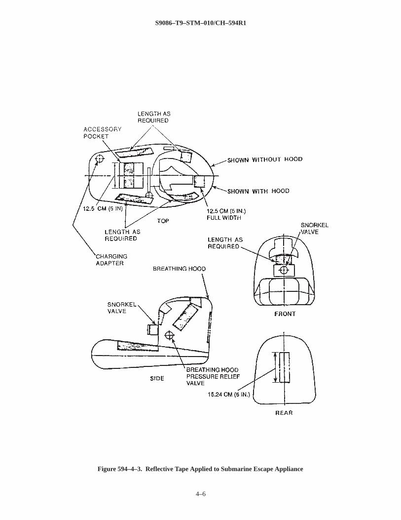
594–4.2.2.15 Reflective Tape. As described in NSTM Chapter 077, strips of reflective tape 51 millimeters (2inches) wide are glued to various areas of the appliance (as shown in Figure 594–4–3) to make the escapee morevisible while on the surface. The reflective tape is applied following the procedures in NSTM Chapter 077.
594–4.2.3 DONNING AND ADJUSTING . Use the following procedures when donning the submarine escapeappliance:
a. Place the belt around your waist. Position the stowage pouch containing the appliance in front. Adjust thebelt for comfort. The belt is properly adjusted if you can place the palms of your hands between the belt and yourhip. The buckle should be on the right side and the chafing pad should be positioned between the metal buckle andyour hip.
b. Remove the appliance from the pouch. Pull the appliance upward and unroll it up over your chest.Ensure that the snorkel valve is in the OPEN position.
c. Ensure that the toggle line, nose clip, whistle, personnel marker light, and sea–dye marker are attached.Ensure that the whistle’s and sea–dye marker’s lanyards are attached to the grommet inside the
S9086–T9–STM–010/CH–594R1
4–6
Figure 594–4–3. Reflective Tape Applied to Submarine Escape Appliance
S9086–T9–STM–010/CH–594R1
4–7
accessory pocket. Stow the whistle and sea–dye marker in the accessory pocket and the toggle line in the smallpocket attached to the waist belt.
d. Inspect the escape appliance for rips, tears, or any other defects. Any hole that is too small to be readilyseen will not seriously reduce the appliance’s effectiveness.
e. Test the escape appliance for proper operation. Partially inflate the buoyancy chamber using the oralinflation device. To do this, the knurled ring must be turned fully clockwise. Holding the tube in one hand, graspthe mouthpiece in the mouth and push in toward the clamp to open the valve. With the valve open, breathe intothe mouthpiece to inflate the buoyancy chamber. Once the buoyancy chamber is partially filled, release themouthpiece and turn the knurled ring counterclockwise so that the mouthpiece cannot be depressed. Squeeze orpress the appliance until air is released through the buoyancy chamber pressure relief valves into the hood. Thisindicates that the relief valves are working properly.
WARNING
While wearing the escape appliance with the hood on before exiting the rescue/escape trunk, breathethrough the snorkel valve and mouthpiece to avoid a buildup of carbon dioxide in the hood.
f. Open the snorkel valve, put on the nose clip, and pass the head through the neck ring and collar.
g. Grip the snorkel valve mouthpiece with your teeth. Breathe only through the mouthpiece and snorkelvalve when wearing the hood to prevent a buildup of carbon dioxide in the hood.
h. If not immediately entering the rescue/escape trunk, remove your head from the hood and carry theappliance over one arm.
594–4.2.4 MAINTENANCE . The submarine escape appliances should be examined carefully before beingstowed aboard the submarine and periodically inspected during stowage to ensure their usability. Inspection andmaintenance shall be performed in accordance with normal maintenance requirements.
594–4.2.5 STOWAGE. Each submarine escape appliance should be properly folded and stored in the attachedrubber–coated cloth stowage pouch. Use the following procedure to prevent damage when packing the applianceinto the pouch:
a. Deflate the appliance using the oral inflation device and lay it flat.
b. Rotate the snorkel valve to OPEN and cover it with a clean rag.
c. Push the snorkel valve inward toward the breathing hood, leaving the rag in place to prevent damage tothe appliance as it is folded.
CAUTION
Do not bend or crease the oral inflation device tube.
d. Fold the sides of the appliance in 51 millimeters (2 inches) to 76 millimeters (3 inches) toward the centerof the appliance.
e. Flatten out the hood.
S9086–T9–STM–010/CH–594R1
4–8
CAUTION
Do not crease the plastic face shield.
f. Press the plastic face shield inward until it dishes. Make sure that it does not crease.
g. Place the lower part of the appliance into the pouch.
h. Roll the appliance down from the top until it is in the pouch.
i. Snap the flap on the pouch shut.
594–4.2.6 PLASTIC FACE SHIELD REPAIR . Because of improper folding, cracks have formed in the plasticface shields on some submarine escape appliances. A procedure has been developed to repair the face shield usingpolyethylene tape (Minnesota Mining and Manufacturing Co. No. 480 polyethylene film tape). Properly applied inaccordance with the following steps, the tape suitably repairs the face shield. Repair the face shield as follows:
a. Wash the inside and outside of the face shield with soap and water.
b. Rinse it thoroughly and wipe it completely dry.
c. Cut the 51–millimeter– (2–inch–) wide tape into strips 51 millimeters (2 inches) long.
d. Using a suitable rounded surface for a backing (e.g., a coffee mug, etc.), lay out the cracked area of theface shield as smoothly as possible.
e. With the rounded backing in place, center the adhesive tape strips lengthwise, allowing about 25millimeters (1 inch) on either side of the crack. Press down firmly to remove as many air pockets as possible.
f. If more than one piece of tape is needed to properly seal the crack, overlap each piece by approximately6 millimeters (1/4 inch) following the instructions in step e..
g. Repeat steps c. through f. on the inside of the face shield.
h. Visually inspect both sides of the face shield to ensure that the crack is properly sealed.
i. Repack the appliance as described in paragraph 594–4.2.5.
594–4.3 SUBMARINE RESCUE/ESCAPE TRUNK
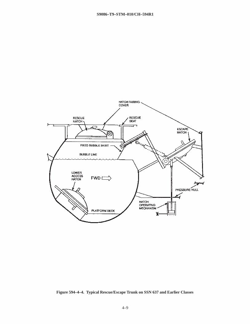
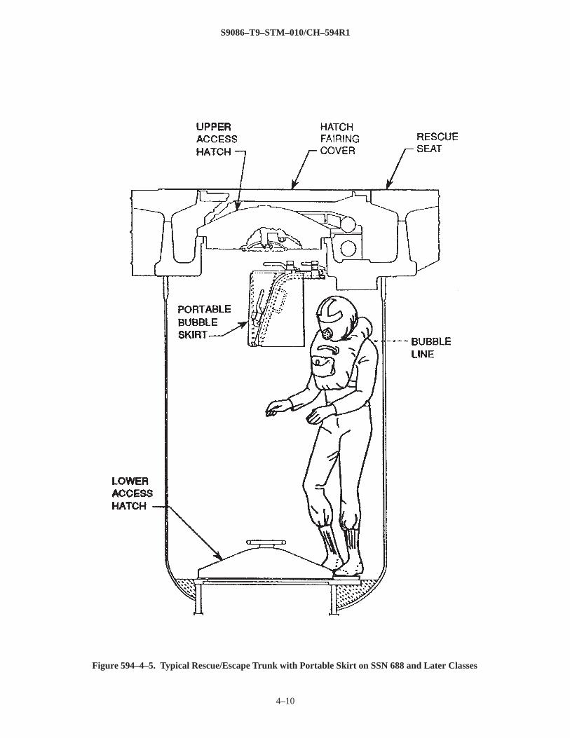
594–4.3.1 DESCRIPTION . Submarines normally have identical cylindrical rescue/escape trunks(Figure 594–4–4 and Figure 594–4–5) serving each main compartment. Each trunk typically holds two individualsat a time when being used during individual escape. Each trunk is closed at the top and bottom by hatches and isequipped with the necessary systems to permit flooding, pressurizing, venting, and draining. These functions canbe controlled from within the trunk and below it in the access compartment to the trunk. It is also possible tooperate the upper access hatch used for escape from within the submarine.
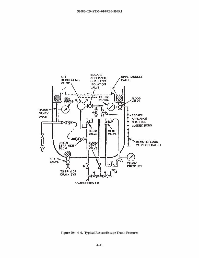
594–4.3.2 FEATURES. Rescue/escape trunks have the following features (Figure 594–4–4, Figure 594–4–5, andFigure 594–4–6) that allow them to be used for individual escape from the submarine using a submarine escapeappliance.
594–4.3.2.1 Hatches. Each trunk typically has 30–inch–diameter upper and lower access hatches. Earlier classesof submarines, such as SSN 637, have three 25–inch–diameter hatches as shown on Figure 594–4–4. The lowerhatch is spring–
S9086–T9–STM–010/CH–594R1
4–9
Figure 594–4–4. Typical Rescue/Escape Trunk on SSN 637 and Earlier Classes
S9086–T9–STM–010/CH–594R1
4–10
Figure 594–4–5. Typical Rescue/Escape Trunk with Portable Skirt on SSN 688 and Later Classes
S9086–T9–STM–010/CH–594R1
4–11
Figure 594–4–6. Typical Rescue/Escape Trunk Features
S9086–T9–STM–010/CH–594R1
4–12
balanced for manual opening and closing. The upper hatch is spring–balanced for manual opening and has amechanical or hydraulic mechanism to assist in operating the hatch from within the submarine. On earlier classesof submarines with separate rescue and escape hatches, the escape hatch has a mechanism to assist in itsoperation.
594–4.3.2.2 Portable Bubble Skirt. A portable bubble skirt is installed in the rescue/escape trunk for use duringescape operations. The skirt traps an air bubble at the top of the trunk. This allows the escapees to maintain theirheads above water after the trunk is flooded. SSN 637 class and earlier submarines have fixed bubble skirts. SSN688 class and later submarines typically have portable bubble skirts. The portable skirt has a rubber gasket andmanually operated dogs for sealing against a mating surface in the trunk.
594–4.3.2.3 Flooding System. The flooding system is used to fill the trunk with seawater to the bubble line inpreparation for escape. The system typically consists of a manually operated, two–position ball valve and tailpiecewith a two–station operator. The two–station operator permits the valve to be operated from either inside the trunkor from below the trunk in the access compartment.
594–4.3.2.4 Blow and Vent System. The blow and vent system is used to pressurize the trunk when it is flooded,reduce the concentration of carbon dioxide in the trunk, and reduce the pressure in the trunk at the end of theescape procedure. This system can be operated from inside the trunk or from below the trunk in the accesscompartment. The system typically has redundant piping penetrations with associated valves rather than a singlevalve with dual controls.
594–4.3.2.5 Air Charging System. The air charging system, which is supplied from the trunk blow and ventsystem, is provided to charge the submarine escape appliances with breathable air. The air is supplied through aregulating valve that is normally set for 100 psi above ambient trunk pressure. The air passes through an isolationvalve to a manifold typically containing two escape appliance charging connections.
594–4.3.2.6 Trunk Drain System. The trunk drain system typically consists of a valve mounted at the bottom ofthe trunk below the level of the lower access hatch coaming. Any accumulated water can be drained to the maindrain system, trim and drain system, or the compartment, depending on the location of the trunk and theconditions in the submarine. For detailed information on draining the trunk, see the applicable ship systemsmanual.
594–4.3.2.7 Upper Hatch Cavity Drain System. The upper access hatch is recessed below the molded line ofthe submarine’s hull, which creates a large cavity in which water is trapped after the submarine surfaces. Theupper hatch cavity drain system provides the piping necessary to drain this area before opening the upper accesshatch.
594–4.3.2.8 Overhead Light. A lamp is installed in the trunk above the bubble line for light. The lamp isenergized by either the normal or emergency lighting system through a selector switch installed below the trunk inthe access compartment.
594–4.3.2.9 Portable Hand Lanterns. Battle lanterns and mounting brackets are installed in the trunk above thebubble line or are stored below the trunk in the access compartment. The lanterns provide lighting if the overheadlight fails.
S9086–T9–STM–010/CH–594R1
4–13
594–4.3.2.10 Loudspeaker. A loudspeaker, which is part of the amplified communications system (IC circuit31MC), is mounted above the bubble line. The loudspeaker allows the occupants of the trunk to communicatewith the personnel below the trunk in the access compartment. A similar loudspeaker is also located below thetrunk in the access compartment.
594–4.3.2.11 Hammer Signal Code Plate. The hammer signal code plate is mounted on the inside of the trunkabove the bubble line. The plate contains information necessary for escapees to communicate by hammer tapswith parties outside the trunk in case all other communication fails. A similar plate is located below the trunk inthe access compartment.
594–4.3.2.12 Allowable Bottom Time Chart. The allowable bottom time chart is installed in the trunk above thebubble line. This chart provides a list of times versus depths of the submarine that the escapees must not exceedafter the trunk is pressurized. A similar allowable bottom time chart is located below the trunk in the accesscompartment.
594–4.3.2.13 Hammer. A hammer mounted above the bubble line is provided for communicating with personneloutside of the trunk in case all other communication systems have failed. A hammer is also located below thetrunk in the access compartment.
594–4.3.2.14 Valve Persuader. A short piece of pipe is mounted above the bubble line on some classes ofsubmarines. This piece of pipe is used to assist in opening and shutting the flood valve during escape operations.The pipe is installed on the end of the valve handle for more leverage when attempting to open the valve.
594–4.3.2.15 Diver’s Knife . A diver’s knife is stowed in the trunk and is used to clear away objects that mayobstruct an escape or prevent proper seating of the upper access hatch.
594–4.3.2.16 Mechanical Timer. A mechanical timer is installed in the trunk above the bubble line. The timer isspring–driven and comes equipped with a knob that allows the timer to be wound up before use.
594–4.3.2.17 Steinke Hood Operating Procedure Plate. The Steinke hood operating procedure plate is mountedon the inside of the trunk above the bubble line. The plate provides instructions on how to properly inflate and usethe escape appliance.
594–4.4 INDIVIDUAL ESCAPE PROCEDURE
594–4.4.1 GENERAL . Because of the variety among submarine classes, detailed escape procedures are notcontained here. To conduct successful individual escape operations, refer to the applicable ship systems manualsfor detailed instructions and procedures for using the rescue/escape trunk.
594–4.4.2 PHYSIOLOGICAL EFFECTS DURING INDIVIDUAL ESCAPE . Escape operations subject thehuman body to certain physiological stresses that, if not understood and accounted for, can result in severe injuryor death. For detailed information on these physiological effects, see NAVSEA 0994–LP–001–9010, U.S. NavyDiving Manual Volume 1 (Air Diving) .
S9086–T9–STM–010/CH–594R1
4–14
594–4.4.2.1 Effects of Increased Pressure on the Body. Increased atmospheric pressure in the submarine, suchas might occur during a flooding casualty, increases the amount of nitrogen that is absorbed in the body. Thisincreased amount of nitrogen can produce bubbles in the body upon depressurization during return to the surface.These nitrogen bubbles can form in joints, blood vessels, and the brain if the body cannot eliminate the gas as itdepressurizes. These bubbles can cause extreme pain, paralysis, and even death. This problem is calleddecompression sickness (DCS) or the ”bends.” The total atmospheric pressure and the time one is exposed to thispressure are interrelated variables that affect the amount of nitrogen dissolved in the body tissues, the related riskof developing DCS, and the need for decompression treatment upon reaching the surface. In general, body tissuesare considered to have absorbed the maximum amount of nitrogen after exposure to a pressurized atmosphere for24 hours. Therefore, personnel preparing to escape from a pressurized submarine may already be saturated withnitrogen. During the escape procedure, personnel are rapidly exposed to higher pressures as the rescue/escapetrunk pressure is equalized with the surrounding sea pressure. This will increase the amount of nitrogen in thebody even more. During the ascent to the surface, the escapee will experience rapid decompression, which maylead to the development of DCS. The ascent rate when using the Steinke hood is 129.5 meters per minute (425feet per minute). To minimize the risk of developing DCS upon reaching the surface, the elapsed time from initialtrunk pressurization until exit of the last escapee must be as short as possible. An allowable bottom time chart isposted in each trunk; the maximum allowable exposure times listed on the chart apply to escape from anunpressurized submarine. In general, all escapees should exit the trunk as soon as possible after the trunk ispressurized.
594–4.4.2.2 Effects of Rapid Pressurization on the Ears. As the trunk is flooded and pressurized, the rapidincrease in air pressure may cause discomfort to the ears of individuals in the trunk. An escapee who is unable toequalize the ear pressure may feel some pain. This condition is temporary and must not be allowed to delay theescape procedure. In extreme cases, the eardrums may rupture. Escapees should continue the escape procedureand exit the trunk within the allowable bottom time limits despite any discomfort to their ears. Failure to do somay result in much more serious injury as a result of DCS. A ruptured eardrum will cause short–term physicaldiscomfort, but there is normally no permanent damage unless the injury is left unattended.
594–4.4.2.3 Effects of Increased Concentrations of Carbon Dioxide in the Atmosphere. The air pocket formedat the top of the rescue/escape trunk after the trunk is flooded is relatively small. Unless this air pocket isventilated, breathing within the air pocket will increase the concentration of carbon dioxide to dangerous levels,which could lead to asphyxiation. As the rescue/escape trunk is pressurized during the escape process, even lowconcentrations of carbon dioxide in the air pocket can be hazardous, since the body will tend to absorb morecarbon dioxide as the pressure is increased.
594–4.4.2.4 Effects of Increased Concentrations of Nitrogen on the Body. Breathing inert gases at pressure cancause a state of stupor or unconsciousness called narcosis. The most common form is nitrogen narcosis. Nitrogennarcosis can occur while breathing compressed air at depth, for example, when conducting escape operations. Thenarcotic effects of nitrogen will affect each individual differently, varying with the depth at which the individual islocated or the
S9086–T9–STM–010/CH–594R1
4–15
pressure of the air the individual is breathing. The effects may first be noticed at depths greater than 100 feet ofseawater (fsw) and will become more pronounced at depths greater than 150 fsw. The symptoms of nitrogennarcosis include confusion; impaired judgement; a sense of well–being or euphoria; slower reaction time andreflexes; lack of concentration; and difficulty in reasoning, remembering what to do, remembering what hasalready been done, and making accurate observations. Someone developing nitrogen narcosis may show signssuch as: loss of judgment or skill; false feeling of well–being; and tingling and numbness of the lips, gums, andlegs. The ability to concentrate and reason may become impaired; affected individuals may be unable to followinstructions or perform simple tasks. This may affect their ability to properly perform the steps necessary forescape. There is no specific treatment for nitrogen narcosis. To alleviate its effects, individuals must be removedfrom the pressurized environment or brought to shallower depths where the effects are not felt.
594–4.4.3 GENERAL STEPS TAKEN WHEN PREPARING TO ESCAPE . The following general steps areordinarily taken when preparing to escape the submarine through the rescue/escape trunk using the submarineescape appliance:
1. All available hand lanterns and flashlights, along with the rubber life raft, are assembled in the accesscompartment below the rescue/escape trunk.
2. The support systems for the trunk are aligned and operating per the applicable ship system manual.
3. The portable bubble skirt, if applicable, is installed inside the trunk.
4. Personnel put on extra clothing, heavy socks, and watch caps for protection from exposure after reachingthe surface. They button up their shirts, turn up their collars, and tuck their pant legs into their socks. They removeshoes and leave keys, coins, and any other items that will weigh them down.
WARNING
If wearing the escape appliance with the hood on before exiting the trunk, the escapee shall breathethrough the snorkel valve and mouthpiece to avoid a buildup of carbon dioxide in the hood.
5. Personnel don, adjust, and properly test the submarine escape appliance as described in paragraph594–4.2.3.
6. If available, a diver’s depth gage can be used to monitor the internal pressure of the disabled submarine(DISSUB). By knowing the DISSUB’s internal pressure and depth, Figure 594–1–1 can be used to monitor theprobability that survivors will develop DCS upon reaching the surface.
7. The DISSUB’s roll and pitch angles should be verified. The roll and pitch angle at which the DISSUB isresting can affect how far the upper access hatch will open during the escape process. Where the remote upperaccess hatch operating mechanism permits, such as on SSBN 726 class submarines, the crew below the trunk inthe access compartment should help to open the upper access hatch during the escape.
8. All personnel should familiarize themselves with the escape procedure and with the features of therescue/escape trunk.
S9086–T9–STM–010/CH–594R1
4–16
594–4.4.4 GENERAL PROCEDURE FOR BUOYANT FREE–BREATHING METHOD OF SUBMARINEESCAPE. The following section provides a general outline of the sequence of events that occurs when using thetrunk and the submarine escape appliance for individual escape. Detailed procedures are contained in theapplicable ship system manual. Note that the following general procedure refers to the portable bubble skirt,which is not used on SSN 637 class and earlier submarines. Also, the procedure does not refer to side escapehatches, which are on rescue/escape trunk designs that use three hatches, such as those on SSN 637 class andearlier submarines (see Figure 594–4–4).
WARNING
The trunk flood valve is to remain shut until the lower access hatch is closed and dogged to preventinadvertent flooding of the access compartment.
1. The trunk is drained and vented and the upper hatch cavity drain should be blown to clear any debris thatmay prevent rapid flooding of the trunk.
WARNING
The trunk shall be ventilated with fresh air to prevent carbon dioxide from building up in the air bubblewhile personnel are in the trunk and breathing through the snorkel valves.
2. One or two individuals enter the trunk wearing the deflated submarine escape appliance and breathingthrough the snorkel valve using the mouthpiece.
3. The lower access hatch is shut and dogged after the escapees are in the trunk. The trunk is ventilatedwith fresh air for approximately 1 minute to prevent the concentration of carbon dioxide in the air bubble fromreaching toxic levels.
4. The timer is set to agree with the time shown on the allowable bottom time chart for the depth indicatedon the sea pressure gauge in the trunk.
5. The escapees connect the escape appliances to the air charging manifold. The valve that controls air tothe manifold is left shut and the valves that control air to the charging hoses are opened.
6. The escapees undog the upper access hatch and verify visually that the hatch locking ring lugs arecentered between the trunk coaming lugs.
7. The escapees flood the trunk to the bubble line inscribed in the trunk or to the lower edge of the portablebubble skirt if the disabled submarine is not at 0 degrees pitch and 0 degrees roll.
8. The trunk is ventilated with fresh air for at least 15 seconds to prevent the concentration of carbondioxide in the air bubble from reaching toxic levels.
9. The trunk vent valve is closed.
10. The charging valve manifold isolation valve is opened to allow the escape appliances to completelycharge as the trunk is pressurized. The appliances are completely charged when air passes through the buoyancychamber pressure relief valves and into the hood.
S9086–T9–STM–010/CH–594R1
4–17
WARNING
To prevent developing DCS upon reaching the surface, escapees shall exit the trunk as soon as possibleafter the trunk is pressurized and before the applicable time on the allowable bottom time chart isexceeded.
11. The mechanical timer is started at the same time trunk pressurization begins. The trunk is rapidlypressurized. The upper access hatch will open as the trunk pressure equalizes with sea pressure, and the rest of thetrunk opposite the portable bubble skirt will fill with seawater.
12. The pressurization of the trunk is secured when the upper access hatch opens.
13. To begin the ascent to the surface, the escapee exhales completely, then takes a deep breath and holds it.The snorkel valve is shut and the mouthpiece is removed from the mouth. The escape appliance is disconnectedfrom the charging manifold and the escapee should start to breathe normally from the air volume in the hood. Theescapees should exit the trunk as soon as possible to avoid exceeding the allowable bottom time.
14. The escapees duck under the skirt, one at a time, and exit the trunk by passing through the upper hatch.The last man out signals using the 31MC circuit or by hammer taps that the escapees have exited the trunk. If thehammer is used, it should be secured to the inside of the trunk before exiting, not dropped to the bottom of thetrunk. If the hammer is dropped to the bottom of the trunk, it may foul the lower access hatch and prevent it fromopening.
WARNING
Failure to forcibly exhale during the entire ascent to the surface may cause an air embolism, resulting indeath.
15. Upon exiting the trunk, the escapees extend their hands above their heads and clasp their thumbs togetherto help guide themselves to the surface and to avoid debris and other survivors. During the ascent, the escapeesshould forcibly exhale to ensure that pressure does not build up in their lungs. The escapees can shout”HO–HO–HO” as a way to continually exhale during the ascent.
16. Upon reaching the surface, the snorkel valve is opened and the escapees should breathe through themouthpiece. More air can be added to the escape appliance by using the oral inflation device. Survivors shouldstay together to be more visible to search and rescue personnel. It is much easier to locate a group of individualsin the water than a single person. Survivors should use the toggle lines on their escape appliances to tie themselvestogether. Whistles should be used to signal approaching ships and personnel marker lights should be used at nightto signal search and rescue personnel. Individuals should take turns using their sea–dye markers to make theirlocation more visible from the air.
17. If an inflatable raft is available, any injured survivors should be placed in it and the rest of the survivorsshould hang onto the sides. The inflatable raft should be sent to the surface last.
18. Death from hypothermia is a major concern for survivors on the surface. The body loses heat about 24times faster in water than in air of the same temperature.
S9086–T9–STM–010/CH–594R1
4–18
The effects of hypothermia are immediate and rapidly disabling. Hypothermia can occur in water as warm as 22degrees C (72° F). Survivors should keep their hoods on and their heads out of the water to minimize heat lossthrough the head. Survivors should not swim. Swimming increases the loss of body heat. Survivors shouldmaximize body contact by grouping together as much as possible, hugging one another, and intertwining theirlegs.
19. If alone, a survivor should assume the Heat Escape Lessening Posture (HELP) position to cut heat lossfrom the head, chest, and groin. To assume the HELP position, the head should be kept out of the water and thelegs should be pulled up to the chest and held in place by wrapping the arms around the knees.
20. After waiting at least 1 minute after receiving an indication that the last man is leaving the trunk or 1minute after the elapsed bottom time has expired, the upper access hatch is shut from inside the submarine usingthe remote hatch operating mechanism.
21. The trunk is vented and drained from inside the ship.
22. When the trunk is empty and the trunk pressure equals the pressure in the access compartment, the loweraccess hatch is opened for the next escape.
23. The rescue/escape trunk’s flood, blow, vent, and drain cycles can be controlled from inside the accesscompartment, if necessary. See the applicable ship system manuals for more information.
S9086–T9–STM–010/CH–594R1
5–1
SECTION 5. SUBMARINE ESCAPE TRAINING
594–5.1 SUBMARINE SCHOOL
594–5.1.1 GENERAL . The submarine escape appliance is so simple in design and operation that its proper usecan be mastered with minimal formal training. Initial training is provided at Basic Submarine School. Classroomlecture is used to familiarize trainees with the escape appliance, the Submarine Rescue Chamber and DeepSubmergence Rescue Vehicle, the physiological effects of escape, and the arrangement of a typical rescue/escapetrunk using a mock–up. A training facility consisting of a rescue/escape trunk and swimming pool is used tofamiliarize trainees with the operation of the escape appliance and a typical rescue/escape trunk. The facility isalso used to teach proper ascent and surface survival techniques.
594–5.2 ONBOARD SUBMARINE TRAINING
594–5.2.1 GENERAL . Initial training on board a submarine involves a hands–on overview of the operation ofthe submarine rescue/escape trunks and the submarine escape appliance. In addition, a training video entitled”Safe Submarine Escape” is viewed. The video is approximately 16 minutes long. It is unclassified and can beordered by contacting the following:
Commander, Submarine Group 2Code N74Submarine On Board Training
Ask for Submarine On Board Training (SOBT) video number 5. The video discusses proper rescue/escape trunkoperation, proper use of the submarine escape appliance, and provides general information concerning escapeoperations. Watching this video satisfies the requirement that all submarine crews participate in annual submarineescape training.
5–1/(5–2 blank)
S9086-T9-STM-010/CH-594R1
NSTM Chapter 594, Salvage – Submarine Safety Escape and RescueDevices
NAVSEA 4160/1 (REV 5–95) (DESTROY OLD STOCK)
(Insert Classification of TMDER Here) CLASSIFICATION:
1. USE THIS REPORT TO INDICATE DEFICIENCIES, PROBLEMS, AND RECOMMENDATIONS RELATING TO PUBLICATION.2. FOR UNCLASSIFIED TMDERS, FILL IN YOUR RETURN ADDRESS IN SPACE PROVIDED ON THE BACK, FOLD AND TAPE WHERE
INDICATED, AND MAIL. (SEE OPNAVINST 5510H FOR MAILING CLASSIFIED TMDERS.)
1. PUB NO. 2. VOL PART 3. REV. NO./DATE OR TMCH. NO./DATE
SN0116–LP–019–5300
NAVSEA/SPAWAR TECHNICAL MANUAL DEFICIENCY/EVALUATION REPORT (TMDER)(NAVSEA S0005–AA–GYD–030/TMMP & NAVSEAINST 4160.3A)
INSTRUCTIONS: Continue on 8 1/2” x 11” paper if space is needed.
4. SYSTEM/EQUIPMENT IDENTIFICATION
6. REPORT CONTROL NUMBER5. TITLE
7. RECOMMENDED CHANGES TO PUBLICATION
PAGE NO. A.
PARAGRAPHB.
C. RECOMMENDED CHANGES AND REASONS
8. ORIGINATOR’S NAME AND WORKCENTER (Please Print)
9. DATE SIGNED
10. DSN/COMM NO. 11. TRANSMITTED TO
12. SHIP HULL NO. AND/OR STATION ADDRESS (DO NOT ABBREVIATE)
1
DEPARTMENT OF THE NAVY
Official Business
FOLD HERE
FOLD HERE
COMMANDERPORT HUENEME DIVISION CODE 5B00NAVAL SURFACE WARFARE CENTER4363 MISSILE WAYPORT HUENEME, CA 93043–4307
NAVSEA 4160/1 (REV 5/95) BACK
PLACEPOSTAGE
HERE

S9086-T9-STM-010/CH-594R1
NSTM Chapter 594, Salvage – Submarine Safety Escape and RescueDevices
NAVSEA 4160/1 (REV 5–95) (DESTROY OLD STOCK)
(Insert Classification of TMDER Here) CLASSIFICATION:
1. USE THIS REPORT TO INDICATE DEFICIENCIES, PROBLEMS, AND RECOMMENDATIONS RELATING TO PUBLICATION.2. FOR UNCLASSIFIED TMDERS, FILL IN YOUR RETURN ADDRESS IN SPACE PROVIDED ON THE BACK, FOLD AND TAPE WHERE
INDICATED, AND MAIL. (SEE OPNAVINST 5510H FOR MAILING CLASSIFIED TMDERS.)
1. PUB NO. 2. VOL PART 3. REV. NO./DATE OR TMCH. NO./DATE
SN0116–LP–019–5300
NAVSEA/SPAWAR TECHNICAL MANUAL DEFICIENCY/EVALUATION REPORT (TMDER)(NAVSEA S0005–AA–GYD–030/TMMP & NAVSEAINST 4160.3A)
INSTRUCTIONS: Continue on 8 1/2” x 11” paper if space is needed.
4. SYSTEM/EQUIPMENT IDENTIFICATION
6. REPORT CONTROL NUMBER5. TITLE
7. RECOMMENDED CHANGES TO PUBLICATION
PAGE NO. A.
PARAGRAPHB.
C. RECOMMENDED CHANGES AND REASONS
8. ORIGINATOR’S NAME AND WORKCENTER (Please Print)
9. DATE SIGNED
10. DSN/COMM NO. 11. TRANSMITTED TO
12. SHIP HULL NO. AND/OR STATION ADDRESS (DO NOT ABBREVIATE)
1

DEPARTMENT OF THE NAVY
Official Business
FOLD HERE
FOLD HERE
COMMANDERPORT HUENEME DIVISION CODE 5B00NAVAL SURFACE WARFARE CENTER4363 MISSILE WAYPORT HUENEME, CA 93043–4307
NAVSEA 4160/1 (REV 5/95) BACK
PLACEPOSTAGE
HERE