Embed Size (px)
Citation preview

BS EN ISO12213-2:2009
ICS 75.060
NO COPYING WITHOUT BSI PERMISSION EXCEPT AS PERMITTED BY COPYRIGHT LAW
BRITISH STANDARD
Natural gas —Calculation ofcompression factorPart 2: Calculation using molar-composition analysis (ISO12213-2:2006)

This British Standardwas published underthe authority of theStandards Policy andStrategy Committee on 30September 2009© BSI 2009
ISBN 978 0 580 67147 0
Amendments/corrigenda issued since publication
Date Comments
BS EN ISO 12213-2:2009
National foreword
This British Standard is the UK implementation of EN ISO12213-2:2009. It is identical to ISO 12213-2:2006. It supersedes BS ENISO 12213-2:2005 which is withdrawn.The UK participation in its preparation was entrusted to TechnicalCommittee PTI/15, Natural gas and gas analysis.A list of organizations represented on this committee can be obtained onrequest to its secretary.This publication does not purport to include all the necessary provisionsof a contract. Users are responsible for its correct application.Compliance with a British Standard cannot confer immunityfrom legal obligations.

EUROPEAN STANDARD
NORME EUROPÉENNE
EUROPÄISCHE NORM
EN ISO 12213-2
September 2009
ICS 75.060 Supersedes EN ISO 12213-2:2005
English Version
Natural gas - Calculation of compression factor - Part 2: Calculation using molar-composition analysis (ISO 12213-
2:2006)
Gaz naturel - Calcul du facteur de compression - Partie 2: Calcul à partir de l'analyse de la composition molaire (ISO
12213-2:2006)
Erdgas - Berechnung von Realgasfaktoren - Teil 2: Berechnungen basierend auf einer molaren Gasanalyse als
Eingangsgröße (ISO 12213-2:2006)
This European Standard was approved by CEN on 13 August 2009. CEN members are bound to comply with the CEN/CENELEC Internal Regulations which stipulate the conditions for giving this European Standard the status of a national standard without any alteration. Up-to-date lists and bibliographical references concerning such national standards may be obtained on application to the CEN Management Centre or to any CEN member. This European Standard exists in three official versions (English, French, German). A version in any other language made by translation under the respons bility of a CEN member into its own language and notified to the CEN Management Centre has the same status as the official versions. CEN members are the national standards bodies of Austria, Belgium, Bulgaria, Cyprus, Czech Republic, Denmark, Estonia, Finland, France, Germany, Greece, Hungary, Iceland, Ireland, Italy, Latvia, Lithuania, Luxembourg, Malta, Netherlands, Norway, Poland, Portugal, Romania, Slovakia, Slovenia, Spain, Sweden, Switzerland and United Kingdom.
EUROPEAN COMMITTEE FOR STANDARDIZATION C O M I T É E U R O P É E N D E N O R M A LI S A T I O N EUR OP ÄIS C HES KOM ITEE FÜR NOR M UNG
Management Centre: Avenue Marnix 17, B-1000 Brussels
© 2009 CEN All rights of exploitation in any form and by any means reserved worldwide for CEN national Members.
Ref. No. EN ISO 12213-2:2009: E

BS EN ISO 12213-2:2009EN ISO 12213-2:2009 (E)
Foreword
The text of ISO 12213-2:2006 has been prepared by Technical Committee ISO/TC 193 “Natural gas” of the International Organization for Standardization (ISO) and has been taken over as EN ISO 12213-2:2009.
This European Standard shall be given the status of a national standard, either by publication of an identical text or by endorsement, at the latest by March 2010, and conflicting national standards shall be withdrawn at the latest by March 2010.
Attention is drawn to the possibility that some of the elements of this document may be the subject of patent rights. CEN [and/or CENELEC] shall not be held responsible for identifying any or all such patent rights.
This document supersedes EN ISO 12213-2:2005.
According to the CEN/CENELEC Internal Regulations, the national standards organizations of the following countries are bound to implement this European Standard: Austria, Belgium, Bulgaria, Cyprus, Czech Republic, Denmark, Estonia, Finland, France, Germany, Greece, Hungary, Iceland, Ireland, Italy, Latvia, Lithuania, Luxembourg, Malta, Netherlands, Norway, Poland, Portugal, Romania, Slovakia, Slovenia, Spain, Sweden, Switzerland and the United Kingdom.
Endorsement notice
The text of ISO 12213-2:2006 has been approved by CEN as a EN ISO 12213-2:2009 without any modification.

BS EN ISO 12213-2:2009ISO 12213-2:2006(E)
© ISO 2006 – All rights reserved iii
Contents Page
Foreword............................................................................................................................................................ iv 1 Scope ..................................................................................................................................................... 1 2 Normative references ........................................................................................................................... 1 3 Terms and definitions........................................................................................................................... 1 4 Method of calculation ........................................................................................................................... 2 4.1 Principle................................................................................................................................................. 2 4.2 The AGA8-92DC equation .................................................................................................................... 2 4.3 Input variables....................................................................................................................................... 3 4.4 Ranges of application........................................................................................................................... 3 4.5 Uncertainty ............................................................................................................................................ 5 5 Computer program ............................................................................................................................... 7 Annex A (normative) Symbols and units ......................................................................................................... 8 Annex B (normative) Description of the AGA8-92DC method..................................................................... 10 Annex C (normative) Example calculations .................................................................................................. 18 Annex D (normative) Pressure and temperature conversion factors......................................................... 19 Annex E (informative) Performance over wider ranges of application....................................................... 20 Annex F (informative) Subroutines in Fortran for the AGA8-92DC method............................................... 25 Bibliography ..................................................................................................................................................... 32
BS EN ISO 12213-2:2009ISO 12213-2:2006(E)
iv © ISO 2006 – All rights reserved
Foreword
ISO (the International Organization for Standardization) is a worldwide federation of national standards bodies (ISO member bodies). The work of preparing International Standards is normally carried out through ISO technical committees. Each member body interested in a subject for which a technical committee has been established has the right to be represented on that committee. International organizations, governmental and non-governmental, in liaison with ISO, also take part in the work. ISO collaborates closely with the International Electrotechnical Commission (IEC) on all matters of electrotechnical standardization.
International Standards are drafted in accordance with the rules given in the ISO/IEC Directives, Part 2.
The main task of technical committees is to prepare International Standards. Draft International Standards adopted by the technical committees are circulated to the member bodies for voting. Publication as an International Standard requires approval by at least 75 % of the member bodies casting a vote.
Attention is drawn to the possibility that some of the elements of this document may be the subject of patent rights. ISO shall not be held responsible for identifying any or all such patent rights.
ISO 12213-2 was prepared by Technical Committee ISO/TC 193, Natural gas, Subcommittee SC 1, Analysis of natural gas.
This second edition cancels and replaces the first edition (ISO 12213-2:1997), Table 1 of which has been technically revised.
ISO 12213 consists of the following parts, under the general title Natural gas — Calculation of compression factor:
⎯ Part 1: Introduction and guidelines
⎯ Part 2: Calculation using molar-composition analysis
⎯ Part 3: Calculation using physical properties

BS EN ISO 12213-2:2009
INTERNATIONAL STANDARD ISO 12213-2:2006(E)
© ISO 2006 – All rights reserved 1
Natural gas — Calculation of compression factor —
Part 2: Calculation using molar-composition analysis
1 Scope
ISO 12213 specifies methods for the calculation of compression factors of natural gases, natural gases containing a synthetic admixture and similar mixtures at conditions under which the mixture can exist only as a gas.
This part of ISO 12213 specifies a method for the calculation of compression factors when the detailed composition of the gas by mole fractions is known, together with the relevant pressures and temperatures.
The method is applicable to pipeline quality gases within the ranges of pressure p and temperature T at which transmission and distribution operations normally take place, with an uncertainty of about ± 0,1 %. It can be applied, with greater uncertainty, to wider ranges of gas composition, pressure and temperature (see Annex E).
More detail concerning the scope and field of application of the method is given in ISO 12213-1.
2 Normative references
The following referenced documents are indispensable for the application of this document. For dated references, only the edition cited applies. For undated references, the latest edition of the referenced document (including any amendments) applies.
ISO 6976, Natural gas — Calculation of calorific values, density, relative density and Wobbe index from composition
ISO 12213-1, Natural gas — Calculation of compression factor — Part 1: Introduction and guidelines
ISO 80000-4, Quantities and units — Part 4: Mechanics
ISO 80000-5, Quantities and units — Part 5: Thermodynamics
3 Terms and definitions
For the purposes of this document, the terms and definitions given in ISO 12213-1 apply.

BS EN ISO 12213-2:2009ISO 12213-2:2006(E)
2 © ISO 2006 – All rights reserved
4 Method of calculation
4.1 Principle
The method recommended uses an equation based on the concept that pipeline quality natural gas may be uniquely characterized for calculation of its volumetric properties by component analysis. This analysis, together with the pressure and temperature, are used as input data for the method.
The method uses a detailed molar-composition analysis in which all constituents present in amounts exceeding a mole fraction of 0,000 05 should be represented. Typically, this includes all alkane hydrocarbons up to about C7 or C8 together with nitrogen, carbon dioxide and helium.
For other gases, additional components such as water vapour, hydrogen sulfide and ethylene need to be taken into consideration (see Reference [1] in the Bibliography).
For manufactured gases, hydrogen and carbon monoxide are also likely to be significant components.
4.2 The AGA8-92DC equation
The compression factor is determined using the AGA8 detailed characterization equation (denoted hereafter as the AGA8-92DC equation). This is an extended virial-type equation. The equation is described in AGA Report No. 8[1]. It may be written as
( ) ( )18 58
13 131 expn n nk b k
n n n nn n
Z B C b c k cρ ρ ρ ρ ρ= =
= + − + − −∑ ∑m r r r r* *n nC (1)
where
Z is the compression factor;
B is the second virial coefficient;
ρm is the molar density (moles per unit volume);
ρr is the reduced density;
bn, cn, kn are constants (see Table B.1);
nC∗ are coefficients which are functions of temperature and composition.
The reduced density ρr is related to the molar density ρm by the equation
3Kρ ρ=r m (2)
where K is a mixture size parameter.
The molar density can be written as
( )p ZRTρ =m (3)
where
p is the absolute pressure;
R is the universal gas constant;
T is the absolute temperature.

BS EN ISO 12213-2:2009ISO 12213-2:2006(E)
© ISO 2006 – All rights reserved 3
Z is calculated as follows: first the values of B and nC∗ (n = 13 to 58) are calculated, using relationships given in Annex B. Equations (1) and (3) are then solved simultaneously for ρm and Z by a suitable numerical method (see Figure B.1).
4.3 Input variables
The input variables required for use with the AGA8-92DC equation are the absolute pressure, absolute temperature and molar composition.
The composition is required, by mole fraction, of the following components: nitrogen, carbon dioxide, argon, methane, ethane, propane, n-butane, methyl-2-propane (iso-butane), n-pentane, methyl-2-butane (iso-pentane), hexanes, heptanes, octanes, nonanes, decanes, hydrogen, carbon monoxide, hydrogen sulfide, helium, oxygen and water.
NOTE If the mole fractions of the heptanes, octanes, nonanes and decanes are unknown, then use of a composite C6+ fraction may be acceptable. The user should carry out a sensitivity analysis in order to test whether a particular approximation of this type degrades the result.
All components with mole fractions greater than 0,000 05 shall be accounted for. Trace components (such as ethylene) shall be treated as given in Table 1.
If the composition is known by volume fractions, these shall be converted to mole fractions using the method given in ISO 6976. The sum of all mole fractions shall be unity to within 0,000 1.
4.4 Ranges of application
4.4.1 Pipeline quality gas
The ranges of application for pipeline quality gas are as defined below:
absolute pressure 0 MPa u p u 12 MPa
temperature 263 K u T u 338 K
superior calorific value 30 MJ⋅m−3 u HS u 45 MJ⋅m−3
relative density 0,55 u d u 0,80
The mole fractions of the natural-gas components shall be within the following ranges:
methane 0,7 u xCH4 u 1,00
nitrogen 0 u xN2 u 0,20
carbon dioxide 0 u xCO2 u 0,20
ethane 0 u xC2H6 u 0,10
propane 0 u xC3H8 u 0,035
butanes 0 u xC4H10 u 0,015
pentanes 0 u xC5H12 u 0,005
hexanes 0 u xC6 u 0,001
heptanes 0 u xC7 u 0,000 5

BS EN ISO 12213-2:2009ISO 12213-2:2006(E)
4 © ISO 2006 – All rights reserved
octanes plus higher hydrocarbons 0 u xC8+ u 0,000 5
hydrogen 0 u xH2 u 0,10
carbon monoxide 0 u xCO u 0,03
helium 0 u xHe u 0,005
water 0 u xH2O u 0,000 15
Any component for which xi is less than 0,000 05 can be neglected.
Minor and trace components are listed in Table 1.
Table 1 — Minor and trace components
Minor and trace component Assigned component
Oxygen Oxygen
Argon, neon, krypton, xenon Argon
Hydrogen sulfide Hydrogen sufide
Nitrous oxide Carbon dioxide
Ammonia Methane
Ethylene, acetylene, methanol (methyl alcohol), hydrogen cyanide
Ethane
Propylene, propadiene, methanethiol (methyl mercaptan) Propane
Butenes, butadienes, carbonyl sulfide (carbon oxysulfide), sulfur dioxide
n-Butane
Neo-pentane, pentenes, benzene, cyclopentane, carbon disulfide
n-Pentane
All C6−isomers, cyclohexane, toluene, methylcyclopentane n-Hexane
All C7−isomers, ethylcyclopentane, methylcyclohexane, cycloheptane, ethylbenzene, xylenes
n-Heptane
All C8−isomers, ethylcyclohexane n-Octane
All C9−isomers n-Nonane
All C10−isomers and all higher hydrocarbons n-Decane
The method applies only to mixtures in the single-phase gaseous state (above the dew point) at the conditions of temperature and pressure of interest.
4.4.2 Wider ranges of application
The ranges of application tested beyond the limits given in 4.4.1 are:
absolute pressure 0 MPa u p u 65 MPa
temperature 225 K u T u 350 K
relative density 0,55 u d u 0,90
superior calorific value 20 MJ⋅m−3 u HS u 48 MJ⋅m−3

BS EN ISO 12213-2:2009ISO 12213-2:2006(E)
© ISO 2006 – All rights reserved 5
The allowable mole fractions of the major natural-gas components are:
methane 0,50 u xCH4 u 1,00
nitrogen 0 u xN2 u 0,50
carbon dioxide 0 u xCO2 u 0,30
ethane 0 u xC2H6 u 0,20
propane 0 u xC3H8 u 0,05
hydrogen 0 u xH2 u 0,10
The limits for minor and trace gas components are as given in 4.4.1 for pipeline quality gas. For use of the method outside these ranges, see Annex E.
4.5 Uncertainty
4.5.1 Uncertainty for pipeline quality gas
The uncertainty of results for use on all pipeline quality gas within the limits described in 4.4.1 is ± 0,1 % (for the temperature range 263 K to 350 K and pressures up to 12 MPa) (see Figure 1). For temperatures above 290 K and at pressures up to 30 MPa the uncertainty of the result is also ± 0,1 %.
For lower temperatures, the uncertainty of ± 0,1 % is at least maintained for pressures up to about 10 MPa.
This uncertainty level has been determined by comparison with the GERG databank of measurements of the compression factor for natural gases [2], [3]. A detailed comparison was also made with the GRI pVT data on gravimetrically prepared simulated natural-gas mixtures [4], [5].
The uncertainty of the measurements in both databanks used to test the method is of the order of ± 0,1 %.
4.5.2 Uncertainty for wider ranges of application
The estimated uncertainties for calculations of compression factors beyond the limits of quality given in 4.4.1 are discussed in Annex E.
4.5.3 Impact of uncertainties of input variables
Listed in Table 2 are typical values for the uncertainties of the relevant input variables. These values may be achieved under optimum operating conditions.
As a general guideline only, an error propagation analysis using the uncertainties in the input variables produces an additional uncertainty of about ± 0,1 % in the result at 6 MPa and within the temperature range 263 K to 338 K. Above 6 MPa, the additional uncertainties are greater and increase roughly in direct proportion to the pressure.

BS EN ISO 12213-2:2009ISO 12213-2:2006(E)
6 © ISO 2006 – All rights reserved
AGA8-DC92 equation
Key p pressure T temperature
1 ∆Z u ± 0,1 % 2 ∆Z ± 0,1 % to ± 0,2 % 3 ∆Z ± 0,2 % to ± 0,5 %
NOTE The uncertainty limits given are expected to be valid for natural gases and similar gases with xN2 u 0,20, xCO2 u 0,20, xC2H6 u 0,10 and xH2 u 0,10, and for 30 MJ⋅m−3 u HS u 45 MJ⋅m−3 and 0,55 u d u 0,80.
Figure 1 — Uncertainty limits for the calculation of compression factors

BS EN ISO 12213-2:2009ISO 12213-2:2006(E)
© ISO 2006 – All rights reserved 7
Table 2 — Uncertainties of input variables
Input variable Absolute uncertainty
Absolute pressure ± 0,02 MPa
Temperature ± 0,15 K
Mole fraction of
inerts ± 0,001
nitrogen ± 0,001
carbon dioxide ± 0,001
methane ± 0,001
ethane ± 0,001
propane ± 0,000 5
butanes ± 0,000 3
pentanes plus higher hydrocarbons ± 0,000 1
hydrogen and carbon monoxide ± 0,001
4.5.4 Reporting of results
Results for compression factor and molar density shall be reported to four and to five places of decimals, respectively, together with the pressure and temperature values and the calculation method used (ISO 12213-2, AGA8-92DC equation). For verification of calculation procedures, it is useful to carry extra digits.
5 Computer program
Software which implements this International Standard has been prepared. Users of this part of ISO 12213 are invited to contact ISO/TC 193/SC 1, either directly or through their ISO member body, to enquire about the availability of this software.

BS EN ISO 12213-2:2009ISO 12213-2:2006(E)
8 © ISO 2006 – All rights reserved
Annex A (normative)
Symbols and units
Symbol Meaning Units
an Constant in Table B.1 —
B Second virial coefficient m3⋅kmol−1
nijB∗ Mixture interaction coefficient [Equations (B.1) and (B.2)] —
bn Constant in Table B.1 —
cn Constant in Table B.1 —
nC∗ Coefficients which are functions of temperature and composition —
Ei Characteristic energy parameter for ith component (Table B.2) K
Ej Characteristic energy parameter for jth component K
Eij Binary energy parameter for second virial coefficient K
ijE∗ Binary energy interaction parameter for second virial coefficient (Table B.3) —
F Mixture high-temperature parameter —
Fi High-temperature parameter for ith component (Table B.2) —
Fj High-temperature parameter for jth component —
fn Constant in Table B.1 —
G Mixture orientation parameter —
Gi Orientation parameter for ith component (Table B.2) —
Gj Orientation parameter for jth component —
Gij Binary orientation parameter —
ijG∗ Binary interaction parameter for orientation (Table B.3) —
gn Constant in Table B.1 —
HS Superior calorific value MJ⋅m−3
K Size parameter (m3/kmol)1/3
Ki Size parameter for ith component (Table B.2) (m3/kmol)1/3
Kj Size parameter for jth component (m3/kmol)1/3
Kij Binary interaction parameter for size (Table B.3) —
kn Constant in Table B.1 —

BS EN ISO 12213-2:2009ISO 12213-2:2006(E)
© ISO 2006 – All rights reserved 9
Symbol Meaning Units
M Molar mass kg⋅kmol−1
Mi Molar mass of ith component kg⋅kmol−1
N Number of components in gas mixture
n An integer (from 1 to 58) —
p Absolute pressure MPa
Q Quadrupole parameter —
Qi Quadrupole parameter for ith component —
Qj Quadrupole parameter for jth component —
qn Constant (Table B.1) —
R Gas constant (= 0,008 314 510) MJ⋅(kmol⋅K)−1
Si Dipole parameter for ith component (Table B.2) —
Sj Dipole parameter for jth component —
sn Constant (Table B.1) —
T Absolute temperature K
U Mixture energy parameter K
Uij Binary interaction parameter for mixture energy (Table B.3) —
un Constant in Table B.1 —
Wi Association parameter for ith component (Table B.2) —
Wj Association parameter for jth component —
wn Constant (Table B.1) —
xi Mole fraction of ith component in gas mixture —
xj Mole fraction of jth component in gas mixture —
Z Compression factor —
ρ Mass density kg⋅m−3
ρr Reduced density of gas —
ρm Molar density kmol⋅m−3

BS EN ISO 12213-2:2009ISO 12213-2:2006(E)
10 © ISO 2006 – All rights reserved
Annex B (normative)
Description of the AGA8-92DC method
B.1 General
For gas mixtures, the compression factor Z is calculated using the equations given in 4.2. This annex gives a detailed description of the computations and the necessary numerical values. The description is based upon that given in AGA Report No. 8 [1]. A program implementing this description is given in Annex F, and as such provides the correct solution. Other computational procedures are acceptable provided that they can be demonstrated to yield identical numerical results (see Annex C for examples).
B.2 Computer implementation of the AGA8-92DC method
B.2.1 Overview of the calculation procedure
I Input the absolute temperature T, absolute pressure p and mole fraction of each component xi of the mixture.
NOTE For pressure and temperature, values known in any other units will first have to be converted precisely to values in megapascals and kelvins, respectively (see ISO 80000-4 and ISO 80000-5 and Annex D for relevant conversion factors).
II Compute the equation of state coefficients B and nC∗ (n = 13 to 58) that depend on T and xi.
III Solve iteratively for the molar density ρm, using the equation of state rearranged to give the pressure p.
IV Output the compression factor after the computed pressure from step III and the input pressure from step I agree within a specified range of convergence (e.g. 1E-06).
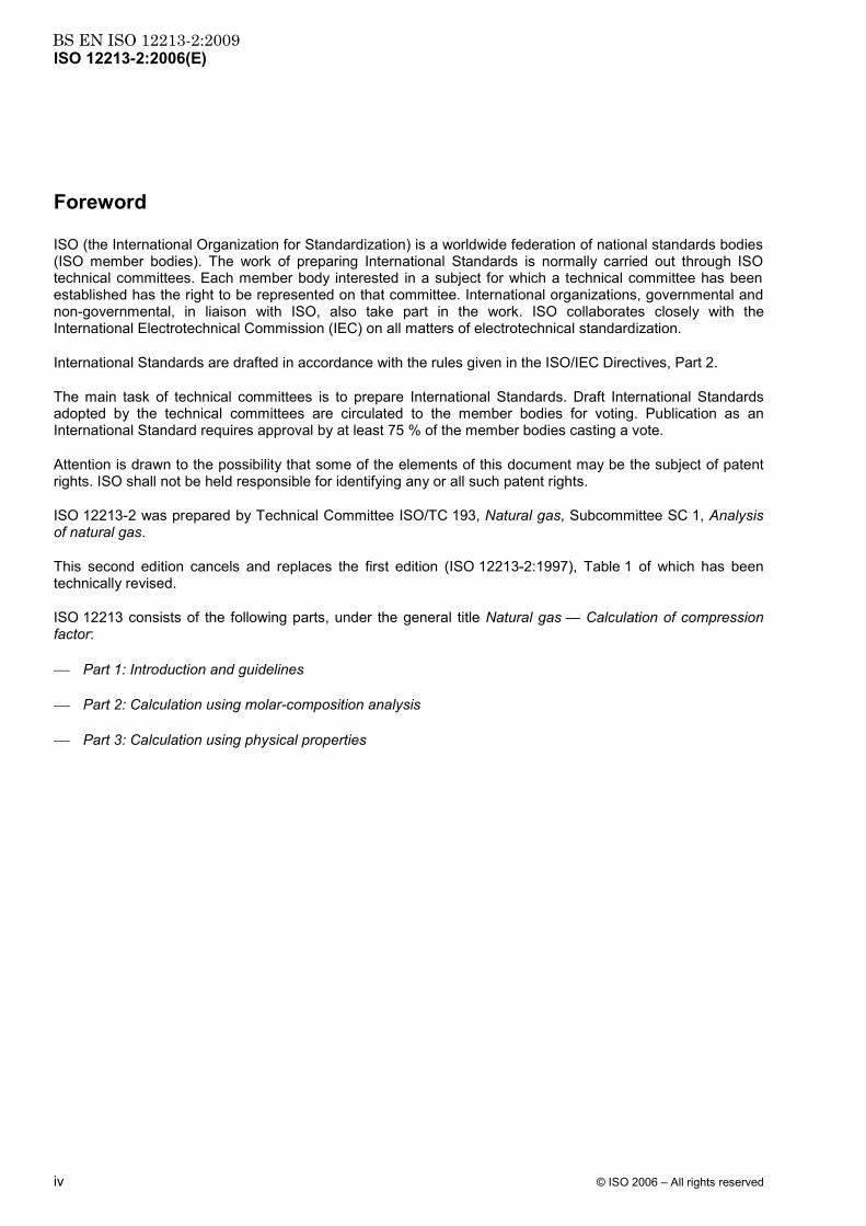
Figure B.1 shows a flow diagram of these steps.
B.2.2 Details of the calculation procedure
Step I
Input the absolute temperature T, absolute pressure p and mole fraction xi of each constituent in the natural-gas mixture.
Step II
At the absolute temperature T and the mole fractions xi of the natural gas (as input from step I), compute the composition- and temperature-dependent coefficients B and nC∗ (n = 13 to 58).
The second virial coefficient B is given by the following equations:
( )18 3 2
*
1 1 1
nnN N
uun i j i jijnij
n i jB a T x x B E K K−
= = =
= ∑ ∑ ∑ (B.1)
( ) ( ) ( ) ( ) ( )1 2 1 2* 1 1 1 1 1nn n n nfg q s w
nij ij n i j n n i j n i j ni jB G g Q Q q F F f S S s W W w= + − + − + − + − + − (B.2)
BS EN ISO 12213-2:2009ISO 12213-2:2006(E)
© ISO 2006 – All rights reserved 11
Figure B.1 — AGA8-92DC equation — Calculation flow diagram
The binary parameters Eij and Gij are calculated using the following equations:
( )1 2*ij ij i jE E E E= (B.3)
( )* 2ij ij i jG G G G= + (B.4)
Note that all values of the binary interaction parameters ijE∗ and ijG∗ are 1,0 except for the values given in Table B.3.

BS EN ISO 12213-2:2009ISO 12213-2:2006(E)
12 © ISO 2006 – All rights reserved
The coefficients nC∗ (n = 13 to 58) are given by the equation:
( ) ( ) ( )* 21 1 1nn n n nqg f u u
n n n n nC a G g Q q F f U T −= + − + − + − (B.5)
The mixture parameters U, G, Q and F are calculated using the following conformal solution mixing equations, where in the double sums i ranges from 1 to N - 1 and, for each value of i, j ranges from i + 1 to N:
( )( )2 1 5 25 25 5
1 1 11
NN N
i i j ij i jii i j i
U x E x x U E E−
= = = +
⎛ ⎞⎜ ⎟= + −⎜ ⎟⎝ ⎠∑ ∑ ∑ (B.6)
( )( )1
*
1 1 11
NN N
i i i j ij i ji i j i
G x G x x G G G−
= = = +
= + − +∑ ∑ ∑ (B.7)
1
N
i ii
Q x Q=
= ∑ (B.8)
2
1
N
i ii
F x F=
= ∑ (B.9)
It should be noted that all values of the binary interaction parameters Kij, ijE∗ , ijG∗ and Uij are 1,0 except for the values given in Table B.3. Also note that Fi is zero for all components except hydrogen, for which F(H2) = 1,0, and that Wi is zero for all components except water, for which W(H2O) = 1,0.
Step III
In the computation of the compression factor Z, the composition of the gas is known, the absolute temperature T of the gas is known and the absolute pressure is known. The problem then is to compute the molar density ρm, using the equation of state expression for the pressure p. For this purpose, the definition of the compression factor Z as given in Equation (1) (see 4.2) is substituted into Equation (3) to obtain an equation for the pressure as given in Equation (B.10):
( ) ( )18 58
* *
13 131 expn n nk b k
n n n n n nn n
p RT B C C b c k cρ ρ ρ ρ ρ ρ= =
⎡ ⎤⎢ ⎥= + − + − −⎢ ⎥⎣ ⎦
∑ ∑m m r r r r (B.10)
Equation (B.10) is solved using standard equation of state density search algorithms. Having obtained an equation for the pressure p [Equation (B.10)], the problem is then to search for the value of the molar density ρm that will yield the pressure that is within a preset limit (e.g. 1 × 10⁻⁶) equal to the input pressure.
The reduced density ρr is related to the molar density ρm by the mixture size parameter [see Equation (2) in 4.2].
The mixture size parameter K is calculated using the following equation:
( )( )2 1 5 25 5 2 5
1 1 12 1
NN N
i i i j ij i ji i j i
K x K x x K K K−
= = = +
⎛ ⎞⎜ ⎟= + −⎜ ⎟⎝ ⎠∑ ∑ ∑ (B.11)
Note that in the summations the subscript i refers to the ith component in the gas mixture and the subscript j refers to the jth component in the gas mixture. The quantity N is the number of components in the mixture. Thus, in the single summation, i ranges over the integer values from 1 to N. For example, for a mixture of 12 components, N = 12 and there would be 12 terms in the single sum. In the double summation, i ranges
BS EN ISO 12213-2:2009ISO 12213-2:2006(E)
© ISO 2006 – All rights reserved 13
from 1 to N − 1 and, for each value of i, j ranges from i + 1 to N. For example, for a mixture of 12 components, there would be 66 terms in the double summation if all values of Kij differed from 1,0. However, because many of the values of Kij are 1,0, the number of non-zero terms in the double summation is small for many natural-gas mixtures. Note that all values of Kij are 1,0 except for the values given in Table B.3.
Step IV
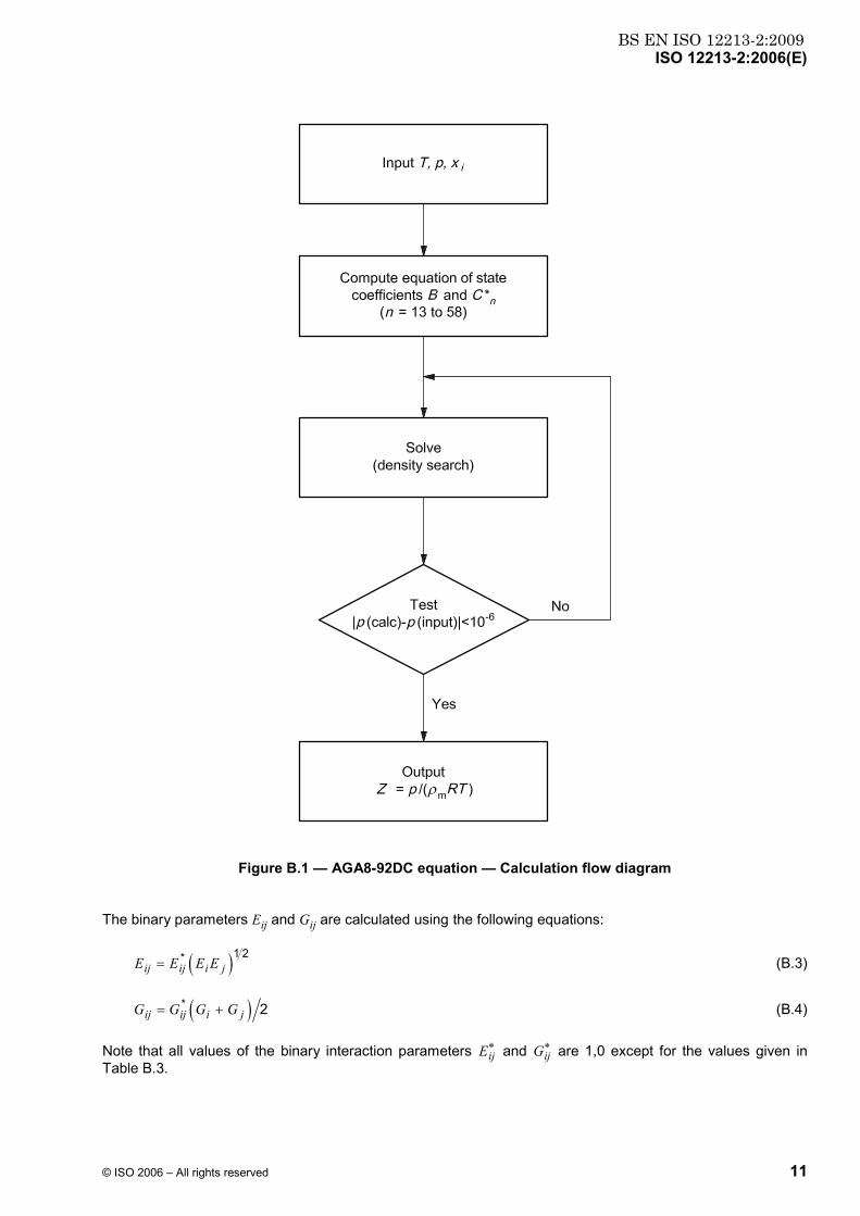
Once the molar density ρm has been obtained in step III, the compression factor is calculated in step IV using the pressure, temperature, molar density and gas constant:
( )Z p RTρ= m (B.12)
NOTE The density ρ (mass per unit volume) can be calculated as follows:
ρ = Mρm (B.13)
where M is calculated from the equation:
1
Ni i
iM x M
== ∑ (B.14)
Report the density to three places of decimals.
Table B.1 — Equation of state parameters
n an bn cn kn un gn qn fn sn wn
1 0,153 832 600 1 0 0 0,0 0 0 0 0 0
2 1,341 953 000 1 0 0 0,5 0 0 0 0 0
3 − 2,998 583 000 1 0 0 1,0 0 0 0 0 0
4 − 0,048 312 280 1 0 0 3,5 0 0 0 0 0
5 0,375 796 500 1 0 0 − 0,5 1 0 0 0 0
6 − 1,589 575 000 1 0 0 4,5 1 0 0 0 0
7 − 0,053 588 470 1 0 0 0,5 0 1 0 0 0
8 0,886 594 630 1 0 0 7,5 0 0 0 1 0
9 − 0,710 237 040 1 0 0 9,5 0 0 0 1 0
10 − 1,471 722 000 1 0 0 6,0 0 0 0 0 1
11 1,321 850 350 1 0 0 12,0 0 0 0 0 1
12 − 0,786 659 250 1 0 0 12,5 0 0 0 0 1
13 2,291 290 × 10−9 1 1 3 − 6,0 0 0 1 0 0
14 0,157 672 400 1 1 2 2,0 0 0 0 0 0
15 − 0,436 386 400 1 1 2 3,0 0 0 0 0 0
16 − 0,044 081 590 1 1 2 2,0 0 1 0 0 0
17 − 0,003 433 888 1 1 4 2,0 0 0 0 0 0
18 0,032 059 050 1 1 4 11,0 0 0 0 0 0
19 0,024 873 550 2 0 0 − 0,5 0 0 0 0 0
20 0,073 322 790 2 0 0 0,5 0 0 0 0 0
21 − 0,001 600 573 2 1 2 0,0 0 0 0 0 0

BS EN ISO 12213-2:2009ISO 12213-2:2006(E)
14 © ISO 2006 – All rights reserved
Table B.1 (continued)
n an bn cn kn un gn qn fn sn wn
22 0,642 470 600 2 1 2 4,0 0 0 0 0 0
23 − 0,416 260 100 2 1 2 6,0 0 0 0 0 0
24 − 0,066 899 570 2 1 4 21,0 0 0 0 0 0
25 0,279 179 500 2 1 4 23,0 1 0 0 0 0
26 − 0,696 605 100 2 1 4 22,0 0 1 0 0 0
27 − 0,002 860 589 2 1 4 − 1,0 0 0 1 0 0
28 − 0,008 098 836 3 0 0 − 0,5 0 1 0 0 0
29 3,150 547 000 3 1 1 7,0 1 0 0 0 0
30 0,007 224 479 3 1 1 − 1,0 0 0 1 0 0
31 − 0,705 752 900 3 1 2 6,0 0 0 0 0 0
32 0,534 979 200 3 1 2 4,0 1 0 0 0 0
33 − 0,079 314 910 3 1 3 1,0 1 0 0 0 0
34 − 1,418 465 000 3 1 3 9,0 1 0 0 0 0
35 − 5,999 05 × 10−17 3 1 4 − 13,0 0 0 1 0 0
36 0,105 840 200 3 1 4 21,0 0 0 0 0 0
37 0,034 317 290 3 1 4 8,0 0 1 0 0 0
38 − 0,007 022 847 4 0 0 − 0,5 0 0 0 0 0
39 0,024 955 870 4 0 0 0,0 0 0 0 0 0
40 0,042 968 180 4 1 2 2,0 0 0 0 0 0
41 0,746 545 300 4 1 2 7,0 0 0 0 0 0
42 − 0,291 961 300 4 1 2 9,0 0 1 0 0 0
43 7,294 616 000 4 1 4 22,0 0 0 0 0 0
44 − 9,936 757 000 4 1 4 23,0 0 0 0 0 0
45 − 0,005 399 808 5 0 0 1,0 0 0 0 0 0
46 − 0,243 256 700 5 1 2 9,0 0 0 0 0 0
47 0,049 870 160 5 1 2 3,0 0 1 0 0 0
48 0,003 733 797 5 1 4 8,0 0 0 0 0 0
49 1,874 951 000 5 1 4 23,0 0 1 0 0 0
50 0,002 168 144 6 0 0 1,5 0 0 0 0 0
51 − 0,658 716 400 6 1 2 5,0 1 0 0 0 0
52 0,000 205 518 7 0 0 − 0,5 0 1 0 0 0
53 0,009 776 195 7 1 2 4,0 0 0 0 0 0
54 − 0,020 487 080 8 1 1 7,0 1 0 0 0 0
55 0,015 573 220 8 1 2 3,0 0 0 0 0 0
56 0,006 862 415 8 1 2 0,0 1 0 0 0 0
57 − 0,001 226 752 9 1 2 1,0 0 0 0 0 0
58 0,002 850 908 9 1 2 0,0 0 1 0 0 0

BS EN ISO 12213-2:2009ISO 12213-2:2006(E)
© ISO 2006 – All rights reserved 15
Table B.2 — Characterization parameters
Identifi-cation
number
Compound Molar mass
Energy parameter
Size parameter
Orientation parameter
Quadrupole parameter
High-temp.
param-eter
Dipole parameter
Associ-ation
param-eter
Mi kg⋅kmol−1
Ei K
Ki (m3/kmol)1/3
Gi Qi Fi Si Wi
1 Methane 16,043 0 151,318 300 0,461 925 5 0,0 0,0 0,0 0,0 0,0
2 Nitrogen 28,013 5 99,737 780 0,447 915 3 0,027 815 0,0 0,0 0,0 0,0
3 Carbon dioxide 44,010 0 241,960 600 0,455 748 9 0,189 065 0,690 000 0,0 0,0 0,0
4 Ethane 30,070 0 244,166 700 0,527 920 9 0,079 300 0,0 0,0 0,0 0,0
5 Propane 44,097 0 298,118 300 0,583 749 0 0,141 239 0,0 0,0 0,0 0,0
6 Water 18,015 3 514,015 600 0,382 586 8 0,332 500 1,067 750 0,0 1,582 200 1,0
7 Hydrogen sulfide 34,082 0 296,355 000 0,461 826 3 0,088 500 0,633 276 0,0 0,390 000 0,0
8 Hydrogen 2,015 9 26,957 940 0,351 491 6 0,034 369 0,0 1,0 0,0 0,0
9 Carbon monoxide 28,010 0 105,534 800 0,453 389 4 0,038 953 0,0 0,0 0,0 0,0
10 Oxygen 31,998 8 122,766 700 0,418 695 4 0,021 000 0,0 0,0 0,0 0,0
11 iso-Butane 58,123 0 324,068 900 0,640 693 7 0,256 692 0,0 0,0 0,0 0,0
12 n-Butane 58,123 0 337,638 900 0,634 142 3 0,281 835 0,0 0,0 0,0 0,0
13 iso-Pentane 72,150 0 365,599 900 0,673 857 7 0,332 267 0,0 0,0 0,0 0,0
14 n-Pentane 72,150 0 370,682 300 0,679 830 7 0,366 911 0,0 0,0 0,0 0,0
15 n-Hexane 86,177 0 402,636 293 0,717 511 8 0,289 731 0,0 0,0 0,0 0,0
16 n-Heptane 100,204 0 427,722 630 0,752 518 9 0,337 542 0,0 0,0 0,0 0,0
17 n-Octane 114,231 0 450,325 022 0,784 955 0 0,383 381 0,0 0,0 0,0 0,0
18 n-Nonane 128,258 0 470,840 891 0,815 273 1 0,427 354 0,0 0,0 0,0 0,0
19 n-Decane 142,285 0 489,558 373 0,843 782 6 0,469 659 0,0 0,0 0,0 0,0
20 Helium 4,002 6 2,610 111 0,358 988 8 0,0 0,0 0,0 0,0 0,0
21 Argon 39,948 0 119,629 900 0,421 655 1 0,0 0,0 0,0 0,0 0,0

BS EN ISO 12213-2:2009ISO 12213-2:2006(E)
16 © ISO 2006 – All rights reserved
Table B.3 — Binary interaction parameter values
Identification number Component pair ijE ∗ Uij Kij ijG ∗
i j
1 2 Methane + nitrogen 0,971 640 0,886 106 1,003 630
3 carbon dioxide 0,960 644 0,963 827 0,995 933 0,807 653
4 ethane
5 propane 0,994 635 0,990 877 1,007 619
6 water 0,708 218
7 hydrogen sulfide 0,931 484 0,736 833 1,000 080
8 hydrogen 1,170 520 1,156 390 1,023 260 1,957 310
9 carbon monoxide 0,990 126
10 oxygen
11 iso-butane 1,019 530
12 n-butane 0,989 844 0,992 291 0,997 596
13 iso-pentane 1,002 350
14 n-pentane 0,999 268 1,003 670 1,002 529
15 n-hexane 1,107 274 1,302 576 0,982 962
16 n-heptane 0,880 880 1,191 904 0,983 565
17 n-octane 0,880 973 1,205 769 0,982 707
18 n-nonane 0,881 067 1,219 634 0,981 849
19 n-decane 0,881 161 1,233 498 0,980 991
2 3 Nitrogen + carbon dioxide 1,022 740 0,835 058 0,982 361 0,982 746
4 ethane 0,970 120 0,816 431 1,007 960
5 propane 0,945 939 0,915 502
6 water 0,746 954
7 hydrogen sulfide 0,902 271 0,993 476 0,942 596
8 hydrogen 1,086 320 0,408 838 1,032 270
9 carbon monoxide 1,005 710
10 oxygen 1,021 000
11 iso-butane 0,946 914
12 n-butane 0,973 384 0,993 556
13 iso-pentane 0,959 340
14 n-pentane 0,945 520
3 4 Carbon dioxide + ethane 0,925 053 0,969 870 1,008 510 0,370 296
5 propane 0,960 237
6 water 0,849 408 1,673 090
7 hydrogen sulfide 0,955 052 1,045 290 1,007 790
8 hydrogen 1,281 790
9 carbon monoxide 1,500 000 0,900 000

BS EN ISO 12213-2:2009ISO 12213-2:2006(E)
© ISO 2006 – All rights reserved 17
Table B.3 (continued)
Identification number Component pair ijE ∗ Uij Kij ijG ∗
i j
10 oxygen
11 iso-butane 0,906 849
12 n-butane 0,897 362
13 iso-pentane 0,726 255
14 n-pentane 0,859 764
15 n-hexane 0,855 134 1,066 638 0,910 183
16 n-heptane 0,831 229 1,077 634 0,895 362
17 n-octane 0,808 310 1,088 178 0,881 152
18 n-nonane 0,786 323 1,098 291 0,867 520
19 n-decane 0,765 171 1,108 021 0,854 406
4 5 Ethane + propane 1,022 560 1,065 173 0,986 893
6 water 0,693 168
7 hydrogen sulfide 0,946 871 0,971 926 0,999 969
8 hydrogen 1,164 460 1,616 660 1,020 340
9 carbon monoxide
10 oxygen
11 iso-butane 1,250 000
12 n-butane 1,013 060 1,250 000
13 iso-pentane 1,250 000
14 n-pentane 1,005 320 1,250 000
5 8 Propane + hydrogen 1,034 787
12 n-butane 1,004 900
7 15 Hydrogen sulfide + n-hexane 1,008 692 1,028 973 0,968130
16 n-heptane 1,010 126 1,033 754 0,962870
17 n-octane 1,011 501 1,038 338 0,957828
18 n-nonane 1,012 821 1,042 735 0,952 441
19 n-decane 1,014 089 1,046 966 0,948 338
8 9 Hydrogen + carbon monoxide 1,100 000
10 oxygen
11 iso-butane 1,300 000
12 n-butane 1,300 000

BS EN ISO 12213-2:2009ISO 12213-2:2006(E)
18 © ISO 2006 – All rights reserved
Annex C (normative)
Example calculations
The following example calculations have been carried out using the validated computer program described in Reference [1], which incorporates the subroutine described in Annex B.
Table C.1 — Gas analysis in mole fractions
Gas 1 Gas 2 Gas 3 Gas 4 Gas 5 Gas 6
xCO2 0,006 0,005 0,015 0,016 0,076 0,011
xN2 0,003 0,031 0,010 0,100 0,057 0,117
xH2 0,00 0,00 0,00 0,095 0,00 0,00
xCO 0,00 0,00 0,00 0,010 0,00 0,00
xCH4 0,965 0,907 0,859 0,735 0,812 0,826
xC2H6 0,018 0,045 0 0,085 0,033 0,043 0,035
xC3H8 0,004 5 0,008 4 0,023 0,007 4 0,009 0,007 5
xiso-C4H10 0,001 0 0,001 0 0,003 5 0,001 2 0,001 5 0,001 2
xn-C4H10 0,001 0 0,001 5 0,003 5 0,001 2 0,001 5 0,001 2
xiso-C5H12 0,000 5 0,000 3 0,000 5 0,000 4 0,00 0,000 4
xn-C5H12 0,000 3 0,000 4 0,000 5 0,000 4 0,00 0,000 4
xC6H14 0,000 7 0,000 4 0,00 0,000 2 0,00 0,000 2
xC7H16 0,00 0,00 0,00 0,000 1 0,00 0,000 1
xC8H18 0,00 0,00 0,00 0,000 1 0,00 0,00
Table C.2 — Results (Z-values)
Conditions Gas 1 Gas 2 Gas 3 Gas 4 Gas 5 Gas 6
p
bar
t
°C
60 - 3,15 0,840 53 0,833 48 0,793 80 0,885 50 0,826 09 0,853 80
60 6,85 0,861 99 0,855 96 0,822 06 0,901 44 0,849 69 0,873 70
60 16,85 0,880 06 0,874 84 0,845 44 0,915 01 0,869 44 0,890 52
60 36,85 0,908 67 0,904 66 0,881 83 0,936 74 0,900 52 0,917 23
60 56,85 0,930 11 0,926 96 0,908 68 0,953 18 0,923 68 0,937 30
120 − 3,15 0,721 33 0,710 44 0,641 45 0,810 24 0,695 40 0,750 74
120 6,85 0,760 25 0,750 66 0,689 71 0,837 82 0,737 80 0,785 86
120 16,85 0,793 17 0,784 75 0,731 23 0,861 37 0,773 69 0,815 69
120 36,85 0,845 15 0,838 63 0,796 97 0,899 13 0,830 22 0,863 11
120 56,85 0,883 83 0,878 70 0,845 53 0,927 66 0,872 11 0,898 62

BS EN ISO 12213-2:2009ISO 12213-2:2006(E)
© ISO 2006 – All rights reserved 19
Annex D (normative)
Pressure and temperature conversion factors
If the input variables pressure and temperature are not in the necessary units of megapascals and kelvins, then conversions will have to be made in order to use the Fortran implementation. A selection of appropriate conversion factors is given below.
Pressure
p (MPa) = [p(bar)] × 10−1
p (MPa) = [p(atm)] × 0,101 325
p (MPa) = [p(psia)]/145,038
p (MPa) = [p(psig) + 14,695 9]/145,038
Temperature
T (K) = t(°C) + 273,15
T (K) = [t(°F) − 32]/1,8 + 273,15
T (K) = [t(°R)]/1,8

BS EN ISO 12213-2:2009ISO 12213-2:2006(E)
20 © ISO 2006 – All rights reserved
Annex E (informative)
Performance over wider ranges of application
The AGA8-92DC equation has been comprehensively tested, over the temperature range 263 K to 338 K and at pressures up to 30 MPa, with the GERG data [2], [3] and the Gas Research Institute data [4] for gases within the ranges of composition given for pipeline quality gases (see 4.4.1). Within these limits, the uncertainties are as given in 4.5.
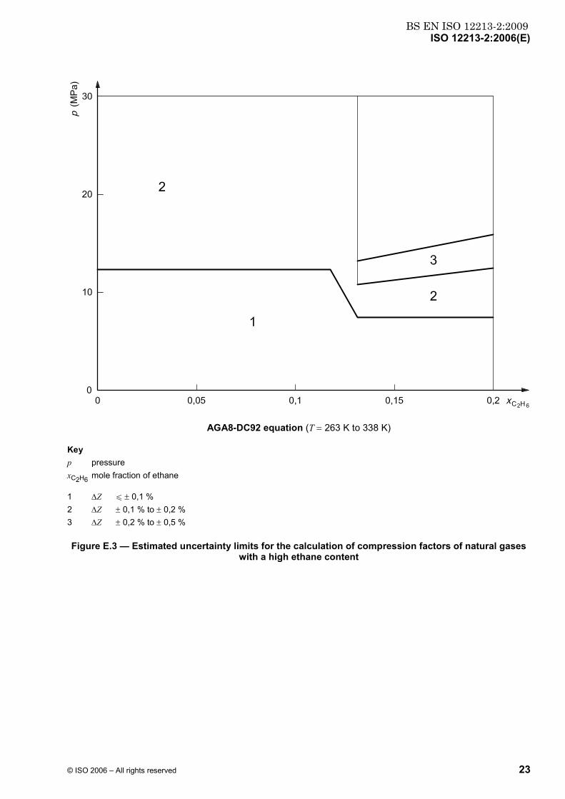
Rough estimates of the uncertainties involved in calculations of compression factors for wider ranges of application (with respect to composition) (see 4.4.2) are plotted in Figures E.1 to E.4 as pressure-composition plots for nitrogen, carbon dioxide, ethane and propane, respectively.
In Figures E.1 to E.4, the performance of the AGA8-92DC method is illustrated up to a maximum pressure of 30 MPa. The uncertainty limits are dependent upon pressure, temperature and composition, and are also strongly affected by the proximity of the phase boundary. The estimated uncertainty limits presented below are based upon less comprehensive data, published as a supplement to the GERG databank [3], and upon the databanks in References [2] and [4]. Reference [4] also provides data up to 70 MPa. The uncertainty limits given in Figures E.1 to E.4 are always for the worst-case result, i.e. they are the least optimistic choice.
Dashed lines are used to separate two regions of estimated uncertainty when the experimental evidence is not sufficient to determine the position of the boundary. The detailed composition of the gas will have a strong influence on the position of the phase boundary and the user should, therefore, make his own phase boundary calculation.

BS EN ISO 12213-2:2009ISO 12213-2:2006(E)
© ISO 2006 – All rights reserved 21
AGA8-DC92 equation (T = 263 K to 338 K)
Key p pressure xN2 mole fraction of nitrogen
1 ∆Z u ± 0,1 % 2 ∆Z ± 0,1 % to ± 0,2 %
Figure E.1 — Estimated uncertainty limits for the calculation of compression factors of natural gases with a high nitrogen content

BS EN ISO 12213-2:2009ISO 12213-2:2006(E)
22 © ISO 2006 – All rights reserved
AGA8-DC92 equation (T = 263 K to 338 K)
Key p pressure xCO2 mole fraction of carbon dioxide
1 ∆Z u ± 0,1 % 2 ∆Z ± 0,1 % to ± 0,2 % 3 ∆Z ± 0,2 % to ± 0,5 % 4 ∆Z ± 0,5 % to ± 3,0 %
Figure E.2 — Estimated uncertainty limits for the calculation of compression factors of natural gases with a high carbon dioxide content
BS EN ISO 12213-2:2009ISO 12213-2:2006(E)
© ISO 2006 – All rights reserved 23
AGA8-DC92 equation (T = 263 K to 338 K)
Key p pressure xC2H6 mole fraction of ethane
1 ∆Z u ± 0,1 % 2 ∆Z ± 0,1 % to ± 0,2 % 3 ∆Z ± 0,2 % to ± 0,5 %
Figure E.3 — Estimated uncertainty limits for the calculation of compression factors of natural gases with a high ethane content

BS EN ISO 12213-2:2009ISO 12213-2:2006(E)
24 © ISO 2006 – All rights reserved
AGA8-DC92 equation (T = 263 K to 338 K)
Key p pressure xC3H8 mole fraction of propane
1 ∆Z u ± 0,1 % 2 ∆Z ± 0,1 % to ± 0,2 %
Figure E.4 — Estimated uncertainty limits for the calculation of compression factors of natural gases with a high propane content
The overall results at pressures up to 10 MPa and temperatures within the range 263 K to 338 K can be summarized as follows. Only gases having mole fractions within the limits given below will have uncertainties within ± 0,1 %, ± 0,2 % and ± 0,5 %, respectively, within the given pressure and temperature domain.
Component Mole fraction for an uncertainty within
± 0,1 % ± 0,2 % ± 0,5 %
Nitrogen u 0,50 — —
Carbon dioxide u 0,23 u 0,26 u 0,28
Ethane u 0,13 u 0,20 —
Propane u 0,06 u 0,10 —

BS EN ISO 12213-2:2009ISO 12213-2:2006(E)
© ISO 2006 – All rights reserved 25
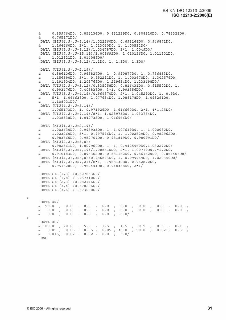
Annex F (informative)
Subroutines in Fortran for the AGA8-92DC method
C C update: 17.05.94 E.W. Lemmon/S.W. Beyerlein/J.L. Savidge C update: 4.09.95 M. Jaeschke J. Sikora =============================================================================== C AGA8-DC92 COMPRESSION FACTOR EQUATION =============================================================================== C SUBROUTINE DCAGA C C This program was written to accompany ISO 12213. C C "DCAGA" Calculates the compression factor of natural gases using C a detailed gas analysis. C C For information contact: DR. Jeffrey L. Savidge C gas research institute C 8600 W. Bryn Mawr Ave. C Chicago, IL 60631 C (312) 399-8100, FAX (312) 399-8125 C C C This program calculates compression factors and molar densities for C natural gases from the input of gas composition in accordance with the C AGA8-DC92 compression equation developed by the Gas C Research Institute, Chicago, Illinois. (K.E. Starling and J.L. C Savidge, Compressibility Factors of Natural Gas and Other Related C Hydrocarbon Gases, American Gas Association, AGA Transmission C Measurement Committee Report No. 8, American Petroleum Institute MPMS C Chapter 14.2, Second Edition, November 1992, Catalog No. XQ9212). C C C The coefficients used in this program are the same as the values found C in AGA Report No. 8, November 1992. C Values for the gas constant and molar masses conform with ISO 6976 C (1995) and GPA 2172 (1988). C C C Ranges of application for compression factor calculation C with the AGA8 - DC92 equation: C C p-T-ranges C absolute pressure 0 to 65 MPa C temperature 225 to 350 K C C Ranges for percentage molar composition: C C A: pipeline quality natural gas C B: wider ranges of application C C A B C methane 70 to 100 50 to 100 C nitrogen 0 to 20 0 to 50 C carbon dioxide 0 to 20 0 to 30 C ethane 0 to 10 0 to 20 C propane 0 to 3.5 0 to 5 C butanes 0 to 1.5 0 to 1.5 C pentanes 0 to 0.5 0 to 0.5

BS EN ISO 12213-2:2009ISO 12213-2:2006(E)
26 © ISO 2006 – All rights reserved
C hexanes 0 to 0.1 0 to 0.1 C heptanes 0 to 0.05 0 to 0.05 C octanes plus 0 to 0.05 0 to 0.05 C hydrogen 0 to 10 0 to 10 C carbon monoxide 0 to 3 0 to 3 C helium 0 to 0.5 0 to 0.5 C water 0 to 0.015 0 to 0.015 C C The expected uncertainty of the calculated results are for C pipeline quality natural gases: C +/- 0,1% within p-T range 0 to 12 MPa, 263 to 350 K C +/- 0,6% within p-T range 0 to 60 MPa, 225 to 350 K C The expected uncertainty in the wider range of application C (composition) is often even for pressures up to 12 MPa larger. C For more details see ISO 12213 part 2. C SUBROUTINE DCAGA (XJ) INTEGER B(58),C(58),K(58),G(58) INTEGER Q(58),F(58),S(58),W(58) REAL*8 A(58),U(58) COMMON /CONSTANTS/ A,B,C,K,U,G,Q,F,S,W REAL*8 MW(21),EI(21),KI(21),GI(21),QI(21),FI(21),SI(21),WI(21) REAL*8 EIJ(21,21),UIJ(21,21),KIJ(21,21),GIJ(21,21) COMMON /PARAMETERS/ MW,EI,KI,GI,QI,FI,SI,WI,EIJ,UIJ,KIJ,GIJ REAL*8 K1, CNS(58), BI(18) COMMON /COEF/ K1, CNS, BI REAL*8 MWX, RGAS, TCM, DCM COMMON /MW/ MWX, RGAS, TCM, DCM INTEGER I, J, N REAL*8 SUM, XI(21), XJ(21) REAL*8 U1, G1, Q1, F1, E1 REAL*8 XIJ, EIJ0, GIJ0, BN XI( 1) = XJ( 1) XI( 4) = XJ( 2) XI( 5) = XJ( 3) XI(11) = XJ( 4) XI(12) = XJ( 5) XI(13) = XJ( 6) XI(14) = XJ( 7) XI(15) = XJ( 8) XI(16) = XJ( 9) XI(17) = XJ(10) XI(18) = XJ(11) XI(19) = XJ(12) XI( 3) = XJ(13) XI( 2) = XJ(14) XI( 7) = XJ(15) XI(20) = XJ(16) XI( 6) = XJ(17) XI(10) = XJ(18) XI(21) = XJ(19) XI( 8) = XJ(20) XI( 9) = XJ(21) C.....Normalize mole fractions SUM = 0 MWX = 0 DO 10 I=1, 21 10 SUM = SUM + XI(I)

BS EN ISO 12213-2:2009ISO 12213-2:2006(E)
© ISO 2006 – All rights reserved 27
DO 20 I=1, 21 20 XI(I) = XI(I)/SUM C.....Calculate molecular weight RGAS = 8.31451D-3 MWX = 0 DO 30 I=1, 21 30 MWX = MWX + XI(I)*MW(I) DO 40 N=1, 18 40 BI(N) = 0 K1 = 0 U1 = 0 G1 = 0 Q1 = 0 F1 = 0 E1 = 0 DO 50 I=1, 21 K1 = K1 + XI(I)*KI(I)**2.5D0 U1 = U1 + XI(I)*EI(I)**2.5D0 G1 = G1 + XI(I)*GI(I) Q1 = Q1 + XI(I)*QI(I) F1 = F1 + XI(I)*XI(I)*FI(I) E1 = E1 + XI(I)*EI(I) 50 CONTINUE TCM = 1.261*E1 DCM = K1**(-1.2D0) K1 = K1*K1 U1 = U1*U1 DO 60 I=1, 8 DO 60 J=I+1, 19 XIJ = XI(I)*XI(J) IF (XIJ.NE.0) THEN K1 = K1+2.D0*XIJ*(KIJ(I,J)**5.D0-1.D0)*(KI(I)*KI(J))**2.5D0 U1 = U1+2.D0*XIJ*(UIJ(I,J)**5.D0-1.D0)*(EI(I)*EI(J))**2.5D0 G1 = G1+XIJ*(GIJ(I,J) - 1.D0)*(GI(I) + GI(J)) ENDIF 60 CONTINUE DO 80 I=1, 21 DO 80 J=I, 21 XIJ = XI(I)*XI(J) IF (XIJ.NE.0) THEN IF (I.NE.J) XIJ = 2.D0*XIJ EIJ0 = EIJ(I,J)*DSQRT(EI(I)*EI(J)) GIJ0 = GIJ(I,J)*(GI(I) + GI(J))/2.D0 DO 70 N=1, 18 BN = (GIJ0 + 1.D0 - G(N))**G(N) & * (QI(I)*QI(J) + 1.D0 - Q(N))**Q(N) & * (DSQRT(FI(I)*FI(J)) + 1.D0 - F(N))**F(N) & * (SI(I)*SI(J) + 1.D0 - S(N))**S(N) & * (WI(I)*WI(J) + 1.D0 - W(N))**W(N) BI(N) = BI(N)+A(N)*XIJ*EIJ0**U(N)*(KI(I)*KI(J))**1.5D0*BN 70 CONTINUE ENDIF 80 CONTINUE K1 = K1**0.2D0 U1 = U1**0.2D0 DO 90 N=13, 58 90 CNS(N) = (G1 + 1.D0 - G(N))**G(N) & * (Q1**2 + 1.D0 - Q(N))**Q(N)

BS EN ISO 12213-2:2009ISO 12213-2:2006(E)
28 © ISO 2006 – All rights reserved
& * (F1 + 1.D0 - F(N))**F(N) & * A(N)*U1**U(N) END C======================================================================= SUBROUTINE PZOFDT(D, T, P, Z, BMIX) INTEGER B(58),C(58),K(58),G(58) INTEGER Q(58),F(58),S(58),W(58) REAL*8 A(58),U(58) COMMON /CONSTANTS/ A,B,C,K,U,G,Q,F,S,W REAL*8 K1, CNS(58), BI(18) COMMON /COEF/ K1, CNS, BI REAL*8 MWX, RGAS, TCM, DCM COMMON /MW/ MWX, RGAS, TCM, DCM INTEGER N REAL*8 D, T, P, Z, BMIX, DR DR = D*K1**3 BMIX = 0 DO 10 N=1, 18 10 BMIX = BMIX + BI(N)/T**U(N) Z = 1.D0 + BMIX*D DO 20 N=13, 18 20 Z = Z - DR*CNS(N)/T**U(N) DO 30 N=13, 58 30 Z = Z + CNS(N)/T**U(N)*(B(N) - C(N)*K(N)*DR**K(N))*DR**B(N) & *DEXP(-C(N)*DR**K(N)) P = D*RGAS*T*Z END C======================================================================= SUBROUTINE DZOFPT(P, T, D, Z, BMIX) REAL*8 P, T, D, Z, BMIX REAL*8 X1, X2, X3, F, F1, F2, F3, TOL INTEGER I TOL = 0.5D-9 X1 = 0.000001D0 X2 = 40.D0 D = 0 CALL PZOFDT(X1, T, F1, Z, BMIX) CALL PZOFDT(X2, T, F2, Z, BMIX) F1 = F1 - P F2 = F2 - P IF (F1*F2.GE.0) RETURN C----------------------------------------------------------------------- C BEGIN ITERATING C----------------------------------------------------------------------- DO 60 I = 1, 50 C ...Use False Position to get point 3. X3 = X1 - F1*(X2 - X1)/(F2 - F1) CALL PZOFDT(X3, T, F3, Z, BMIX) F3 = F3 - P C ...Use points 1, 2, and 3 to estimate the root using Chamber's C ...method (quadratic solution). D = X1*F2*F3/((F1 - F2)*(F1 - F3)) & + X2*F1*F3/((F2 - F1)*(F2 - F3)) & + X3*F1*F2/((F3 - F1)*(F3 - F2))

BS EN ISO 12213-2:2009ISO 12213-2:2006(E)
© ISO 2006 – All rights reserved 29
IF ((D - X1)*(D - X2).GE.0) D = (X1 + X2)/2.D0 CALL PZOFDT(D, T, F, Z, BMIX) F = F - P IF (DABS(F).LE.TOL) RETURN C ...Discard quadratic solution if false position root is closer. IF (DABS(F3).LT.DABS(F) .AND. F*F3.GT.0) THEN IF (F3*F1.GT.0) THEN X1 = X3 F1 = F3 ELSE X2 = X3 F2 = F3 ENDIF ELSE C ...Swap in new value from quadratic solution IF (F*F3.LT.0) THEN X1 = D F1 = F X2 = X3 F2 = F3 ELSEIF (F3*F1.GT.0) THEN X1 = D F1 = F ELSE X2 = D F2 = F ENDIF ENDIF 60 CONTINUE D = 0 END C======================================================================= BLOCK DATA INTEGER B(58),C(58),K(58),G(58) INTEGER Q(58),F(58),S(58),W(58) REAL*8 A(58),U(58) COMMON /CONSTANTS/ A,B,C,K,U,G,Q,F,S,W REAL*8 MW(21),EI(21),KI(21),GI(21),QI(21),FI(21),SI(21),WI(21) REAL*8 EIJ(21,21),UIJ(21,21),KIJ(21,21),GIJ(21,21) COMMON /PARAMETERS/ MW,EI,KI,GI,QI,FI,SI,WI,EIJ,UIJ,KIJ,GIJ REAL*8 XN(21), XH(21) COMMON /GRENZDATA/ XN,XH C.....Equation of state parameters DATA A/ & 0.153832600D0, 1.341953000D0, -2.998583000D0, -0.048312280D0, & 0.375796500D0, -1.589575000D0, -0.053588470D0, 0.886594630D0, & -0.710237040D0, -1.471722000D0, 1.321850350D0, -0.786659250D0, & 0.2291290D-08, 0.157672400D0, -0.436386400D0, -0.044081590D0, & -0.003433888D0, 0.032059050D0, 0.024873550D0, 0.073322790D0, & -0.001600573D0, 0.642470600D0, -0.416260100D0, -0.066899570D0, & 0.279179500D0, -0.696605100D0, -0.002860589D0, -0.008098836D0, & 3.150547000D0, 0.007224479D0, -0.705752900D0, 0.534979200D0, & -0.079314910D0, -1.418465000D0, -0.5999050D-16, 0.105840200D0, & 0.034317290D0, -0.007022847D0, 0.024955870D0, 0.042968180D0, & 0.746545300D0, -0.291961300D0, 7.294616000D0, -9.936757000D0, & -0.005399808D0, -0.243256700D0, 0.049870160D0, 0.003733797D0, & 1.874951000D0, 0.002168144D0, -0.658716400D0, 0.000205518D0, & 0.009776195D0, -0.020487080D0, 0.015573220D0, 0.006862415D0, & -0.001226752D0, 0.002850908D0/ DATA B/1,1,1,1,1,1,1,1,1,1,1,1,1,1,1,1,1,1,2,2,2,2,2,2,2,2,2,3,3,

BS EN ISO 12213-2:2009ISO 12213-2:2006(E)
30 © ISO 2006 – All rights reserved
& 3,3,3,3,3,3,3,3,4,4,4,4,4,4,4,5,5,5,5,5,6,6,7,7,8,8,8,9,9/ DATA C/0,0,0,0,0,0,0,0,0,0,0,0,1,1,1,1,1,1,0,0,1,1,1,1,1,1,1,0,1, & 1,1,1,1,1,1,1,1,0,0,1,1,1,1,1,0,1,1,1,1,0,1,0,1,1,1,1,1,1/ DATA K/0,0,0,0,0,0,0,0,0,0,0,0,3,2,2,2,4,4,0,0,2,2,2,4,4,4,4,0,1, & 1,2,2,3,3,4,4,4,0,0,2,2,2,4,4,0,2,2,4,4,0,2,0,2,1,2,2,2,2/ DATA G/0,0,0,0,1,1,0,0,0,0,0,0,0,0,0,0,0,0,0,0,0,0,0,0,1,0,0,0,1, & 0,0,1,1,1,0,0,0,0,0,0,0,0,0,0,0,0,0,0,0,0,1,0,0,1,0,1,0,0/ DATA Q/0,0,0,0,0,0,1,0,0,0,0,0,0,0,0,1,0,0,0,0,0,0,0,0,0,1,0,1,0, & 0,0,0,0,0,0,0,1,0,0,0,0,1,0,0,0,0,1,0,1,0,0,1,0,0,0,0,0,1/ DATA F/0,0,0,0,0,0,0,0,0,0,0,0,1,0,0,0,0,0,0,0,0,0,0,0,0,0,1,0,0, & 1,0,0,0,0,1,0,0,0,0,0,0,0,0,0,0,0,0,0,0,0,0,0,0,0,0,0,0,0/ DATA S/0,0,0,0,0,0,0,1,1,0,0,0,0,0,0,0,0,0,0,0,0,0,0,0,0,0,0,0,0, & 0,0,0,0,0,0,0,0,0,0,0,0,0,0,0,0,0,0,0,0,0,0,0,0,0,0,0,0,0/ DATA W/0,0,0,0,0,0,0,0,0,1,1,1,0,0,0,0,0,0,0,0,0,0,0,0,0,0,0,0,0, & 0,0,0,0,0,0,0,0,0,0,0,0,0,0,0,0,0,0,0,0,0,0,0,0,0,0,0,0,0/ DATA U/0,0.5D0,1,3.5D0,-0.5D0,4.5D0,0.5D0,7.5D0,9.5D0,6,12,12.5D0, & -6,2,3,2,2,11,-0.5D0,0.5D0,0,4,6,21,23,22,-1,-0.5D0,7,-1,6, & 4,1,9,-13,21,8,-0.5D0,0,2,7,9,22,23,1,9,3,8,23,1.5D0,5, & -0.5D0,4,7,3,0,1,0/ C.....Characterization Parameters DATA MW/16.0430D0, 28.0135D0, 44.0100D0, 30.0700D0, 44.0970D0, & 18.0153D0, 34.0820D0, 2.0159D0, 28.0100D0, 31.9988D0, & 58.1230D0, 58.1230D0, 72.1500D0, 72.1500D0, 86.1770D0, & 100.2040D0,114.2310D0,128.2580D0,142.2850D0, 4.0026D0, & 39.9480D0/ DATA EI/151.318300D0, 99.737780D0, 241.960600D0, 244.166700D0, & 298.118300D0, 514.015600D0, 296.355000D0, 26.957940D0, & 105.534800D0, 122.766700D0, 324.068900D0, 337.638900D0, & 365.599900D0, 370.682300D0, 402.636293D0, 427.722630D0, & 450.325022D0, 470.840891D0, 489.558373D0, 2.610111D0, & 119.629900D0/ DATA KI/0.4619255D0, 0.4479153D0, 0.4557489D0, 0.5279209D0, & 0.5837490D0, 0.3825868D0, 0.4618263D0, 0.3514916D0, & 0.4533894D0, 0.4186954D0, 0.6406937D0, 0.6341423D0, & 0.6738577D0, 0.6798307D0, 0.7175118D0, 0.7525189D0, & 0.7849550D0, 0.8152731D0, 0.8437826D0, 0.3589888D0, & 0.4216551D0/ DATA GI/0, 0.027815D0, 0.189065D0, 0.079300D0, 0.141239D0, & 0.332500D0, 0.088500D0, 0.034369D0, 0.038953D0, 0.021000D0, & 0.256692D0, 0.281835D0, 0.332267D0, 0.366911D0, 0.289731D0, & 0.337542D0, 0.383381D0, 0.427354D0, 0.469659D0, 0, 0/ DATA QI/2*0, 0.69D0, 2*0, 1.06775D0, 0.633276D0, 14*0/ DATA FI/7*0, 1, 13*0/ DATA SI/5*0, 1.5822D0, 0.390D0, 14*0/ DATA WI/5*0, 1, 15*0/ C.....Binary interaction parameters DATA EIJ/441*1/ DATA UIJ/441*1/ DATA KIJ/441*1/ DATA GIJ/441*1/ DATA (EIJ(1,J),J=2,19)/ & 0.971640D0, 0.960644D0, 1, 0.994635D0, 0.708218D0, & 0.931484D0, 1.170520D0, 0.990126D0, 1, 1.019530D0, & 0.989844D0, 1.002350D0, 0.999268D0, 1.107274D0, 0.880880D0, & 0.880973D0, 0.881067D0, 0.881161D0/ DATA (EIJ(2,J),J=3,14)/ & 1.022740D0, 0.970120D0, 0.945939D0, 0.746954D0, 0.902271D0, & 1.086320D0, 1.005710D0, 1.021000D0, 0.946914D0, 0.973384D0, & 0.959340D0, 0.945520D0/ DATA (EIJ(3,J),J=4,19)/ & 0.925053D0, 0.960237D0, 0.849408D0, 0.955052D0, 1.281790D0, & 1.5D0, 1, 0.906849D0, 0.897362D0, 0.726255D0,
BS EN ISO 12213-2:2009ISO 12213-2:2006(E)
© ISO 2006 – All rights reserved 31
& 0.859764D0, 0.855134D0, 0.831229D0, 0.808310D0, 0.786323D0, & 0.765171D0/ DATA (EIJ(4,J),J=5,14)/1.022560D0, 0.693168D0, 0.946871D0, & 1.164460D0, 3*1, 1.013060D0, 1, 1.00532D0/ DATA (EIJ(5,J),J=8,12)/1.034787D0, 3*1, 1.0049D0/ DATA (EIJ(7,J),J=15,19)/1.008692D0, 1.010126D0, 1.011501D0, & 1.012821D0, 1.014089D0/ DATA (EIJ(8,J),J=9,12)/1.1D0, 1, 1.3D0, 1.3D0/ DATA (UIJ(1,J),J=2,19)/ & 0.886106D0, 0.963827D0, 1, 0.990877D0, 1, 0.736833D0, & 1.156390D0, 3*1, 0.992291D0, 1, 1.003670D0, 1.302576D0, & 1.191904D0, 1.205769D0, 1.219634D0, 1.233498D0/ DATA (UIJ(2,J),J=3,12)/0.835058D0, 0.816431D0, 0.915502D0, 1, & 0.993476D0, 0.408838D0, 3*1, 0.993556D0/ DATA (UIJ(3,J),J=4,19)/0.969870D0, 2*1, 1.045290D0, 1, 0.9D0, & 5*1, 1.066638D0, 1.077634D0, 1.088178D0, 1.098291D0, & 1.108021D0/ DATA (UIJ(4,J),J=5,14)/ & 1.065173D0, 1, 0.971926D0, 1.616660D0, 2*1, 4*1.25D0/ DATA (UIJ(7,J),J=7,19)/8*1, 1.028973D0, 1.033754D0, & 1.038338D0, 1.042735D0, 1.046966D0/ DATA (KIJ(1,J),J=2,19)/ & 1.003630D0, 0.995933D0, 1, 1.007619D0, 1, 1.000080D0, & 1.023260D0, 3*1, 0.997596D0, 1, 1.002529D0, 0.982962D0, & 0.983565D0, 0.982707D0, 0.981849D0, 0.980991D0/ DATA (KIJ(2,J),J=3,8)/ & 0.982361D0, 1.007960D0, 1, 1, 0.9425960D0,1.032270D0/ DATA (KIJ(3,J),J=4,19)/1.008510D0, 2*1, 1.00779D0,7*1.0D0, & 0.910183D0, 0.895362D0, 0.881152D0, 0.867520D0, 0.854406D0/ DATA (KIJ(4,J),J=5,8)/0.986893D0, 1, 0.999969D0, 1.020340D0/ DATA (KIJ(7,J),J=7,21)/8*1, 0.968130D0, 0.962870D0, & 0.957828D0, 0.952441D0, 0.948338D0, 2*1/ DATA GIJ(1,3) /0.807653D0/ DATA GIJ(1,8) /1.957310D0/ DATA GIJ(2,3) /0.982746D0/ DATA GIJ(3,4) /0.370296D0/ DATA GIJ(3,6) /1.673090D0/ C DATA XN/ & 50.0 , 0.0 , 0.0 , 0.0 , 0.0 , 0.0 , 0.0 , 0.0 , & 0.0 , 0.0 , 0.0 , 0.0 , 0.0 , 0.0 , 0.0 , 0.0 , & 0.0 , 0.0 , 0.0 , 0.0 , 0.0/ C DATA XH/ & 100.0 , 20.0 , 5.0 , 1.5 , 1.5 , 0.5 , 0.5 , 0.1 , & 0.05 , 0.05 , 0.05 , 0.05 , 30.0 , 50.0 , 0.02 , 0.5 , & 0.015, 0.02 , 0.02 , 10.0 , 3.0/ END

BS EN ISO 12213-2:2009ISO 12213-2:2006(E)
32 © ISO 2006 – All rights reserved
Bibliography
[1] STARLING, K.E., SAVIDGE, J.L. “Compressibility Factors for Natural Gas and Other Related Hydrocarbon Gases”, American Gas Association (AGA) Transmission Measurement Committee Report No. 8, American Petroleum Institute (API) MPMS, chapter 14.2, second edition, November 1992
[2] JAESCHKE, M., HUMPHREYS, A.E. “The GERG Databank of High Accuracy Compressibility Factor Measurements”, GERG Technical Monograph TM4 (1990) and Fortschritt-Berichte VDI, Series 6, No. 251 (1991)
[3] JAESCHKE, M., HINZE, H.M., HUMPHREYS, A.E. “Supplement to the GERG Databank of High Accuracy Compressibility Factor Measurements”, GERG Technical Monograph TM7 (1996) and Fortschritt-Berichte VDI, Series 6, No. 355 (1997)
[4] SCHOUTEN, J.A., MICHELS, J.P.J. “Evaluation of PVT Reference Data on Natural Gas Mixtures — Final report”, Appendix to Gas Research Institute Report No. GRI/93-006, September 1992
[5] SAVIDGE, J.L., BEYERLEIN, S., LEMMON, E. Technical reference document on the 2nd edition of AGA Report No. 8, November 1992 (Gas Research Institute Report No. GRI/93-0181, May 1993)

BS EN ISO 12213-2:2009

BS EN ISO12213-2:2009
BSI GroupHeadquarters 389Chiswick High Road,London, W4 4AL, UKTel +44 (0)20 8996 9001Fax +44 (0)20 8996 7001www.bsigroup.com/standards
BSI - British Standards InstitutionBSI is the independent national body responsible for preparing BritishStandards. It presents the UK view on standards in Europe and at theinternational level. It is incorporated by Royal Charter.
Revisions
British Standards are updated by amendment or revision. Users of BritishStandards should make sure that they possess the latest amendments oreditions.
It is the constant aim of BSI to improve the quality of our products and services.We would be grateful if anyone finding an inaccuracy or ambiguity while usingthis British Standard would inform the Secretary of the technical committeeresponsible, the identity of which can be found on the inside front cover. Tel:+44 (0)20 8996 9000. Fax: +44 (0)20 8996 7400.
BSI offers members an individual updating service called PLUS which ensuresthat subscribers automatically receive the latest editions of standards.
Buying standards
Orders for all BSI, international and foreign standards publications should beaddressed to Customer Services. Tel: +44 (0)20 8996 9001. Fax: +44 (0)20 89967001 Email: [email protected] You may also buy directly using a debit/creditcard from the BSI Shop on the Website http://www.bsigroup.com/shop
In response to orders for international standards, it is BSI policy to supply theBSI implementation of those that have been published as British Standards,unless otherwise requested.
Information on standards
BSI provides a wide range of information on national, European andinternational standards through its Library and its Technical Help to ExportersService. Various BSI electronic information services are also available whichgive details on all its products and services. Contact Information Centre. Tel:+44 (0)20 8996 7111 Fax: +44 (0)20 8996 7048 Email: [email protected]
Subscribing members of BSI are kept up to date with standards developmentsand receive substantial discounts on the purchase price of standards. For detailsof these and other benefits contact Membership Administration. Tel: +44 (0)208996 7002 Fax: +44 (0)20 8996 7001 Email: [email protected]
Information regarding online access to British Standards via British StandardsOnline can be found at http://www.bsigroup.com/BSOL
Further information about BSI is available on the BSI website at http://www.bsigroup.com.
Copyright
Copyright subsists in all BSI publications. BSI also holds the copyright, in theUK, of the publications of the international standardization bodies. Except aspermitted under the Copyright, Designs and Patents Act 1988 no extract maybe reproduced, stored in a retrieval system or transmitted in any form or by anymeans – electronic, photocopying, recording or otherwise – without prior writtenpermission from BSI.
This does not preclude the free use, in the course of implementing the standard,of necessary details such as symbols, and size, type or grade designations. Ifthese details are to be used for any other purpose than implementation then theprior written permission of BSI must be obtained.
Details and advice can be obtained from the Copyright and Licensing Manager.Tel: +44 (0)20 8996 7070 Email: [email protected]