Embed Size (px)
Citation preview
1
Channel Utilization Schemes
2
Introduction
Multiplexing schemes TDMA FDMA CDMA
Compression Analog signal compression
Voice compression Data compression
Data compression Fax compression
3
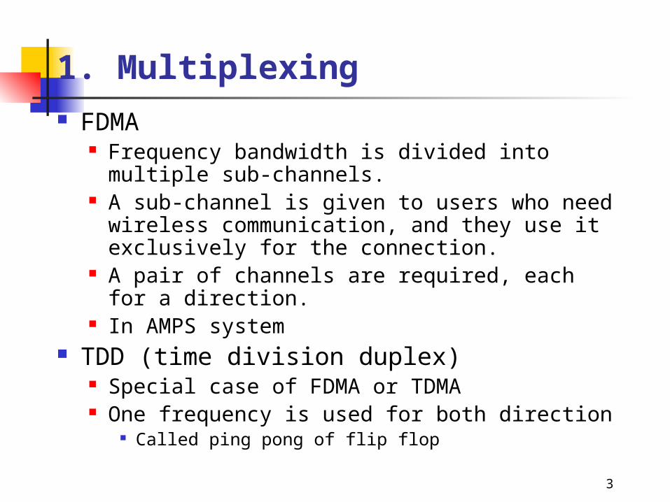
1. Multiplexing FDMA
Frequency bandwidth is divided into multiple sub-channels.
A sub-channel is given to users who need wireless communication, and they use it exclusively for the connection.
A pair of channels are required, each for a direction. In AMPS system
TDD (time division duplex) Special case of FDMA or TDMA One frequency is used for both direction
Called ping pong of flip flop
4
1. Multiplexing
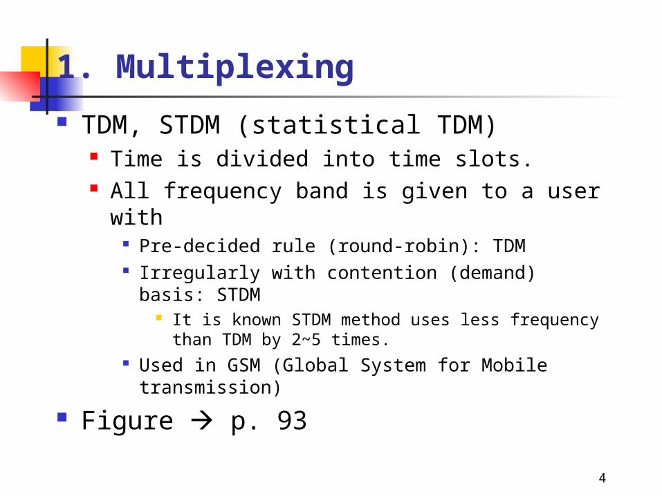
TDM, STDM (statistical TDM) Time is divided into time slots. All frequency band is given to a user with
Pre-decided rule (round-robin): TDM Irregularly with contention (demand) basis: STDM
It is known STDM method uses less frequency than TDM by 2~5 times.
Used in GSM (Global System for Mobile transmission)
Figure p. 93
5
1. Multiplexing
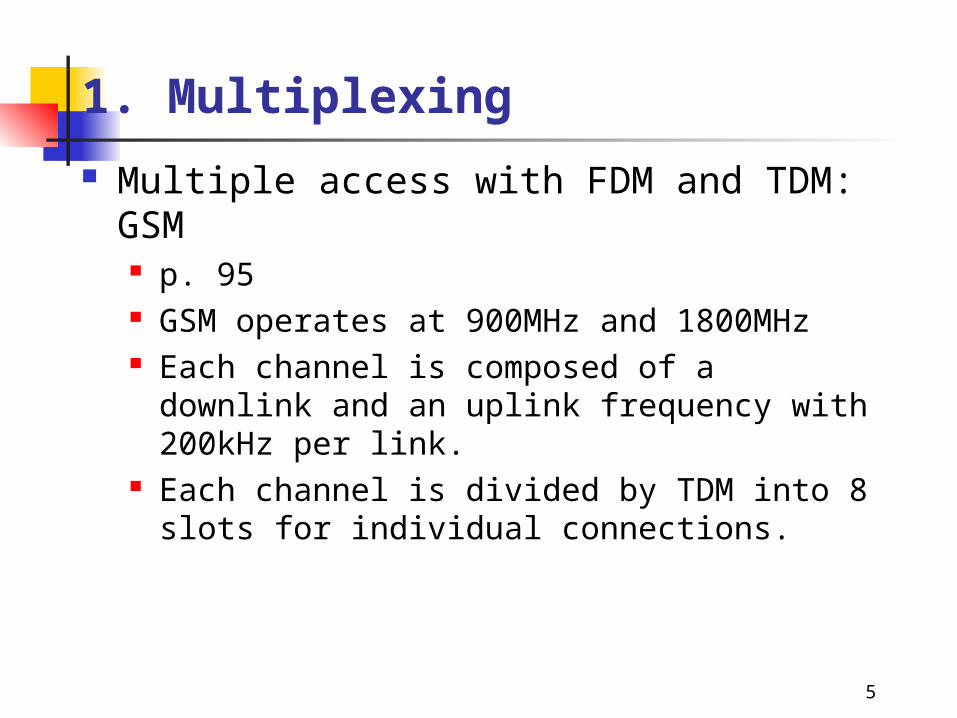
Multiple access with FDM and TDM: GSM p. 95 GSM operates at 900MHz and 1800MHz Each channel is composed of a downlink and an uplink
frequency with 200kHz per link. Each channel is divided by TDM into 8 slots for
individual connections.
6
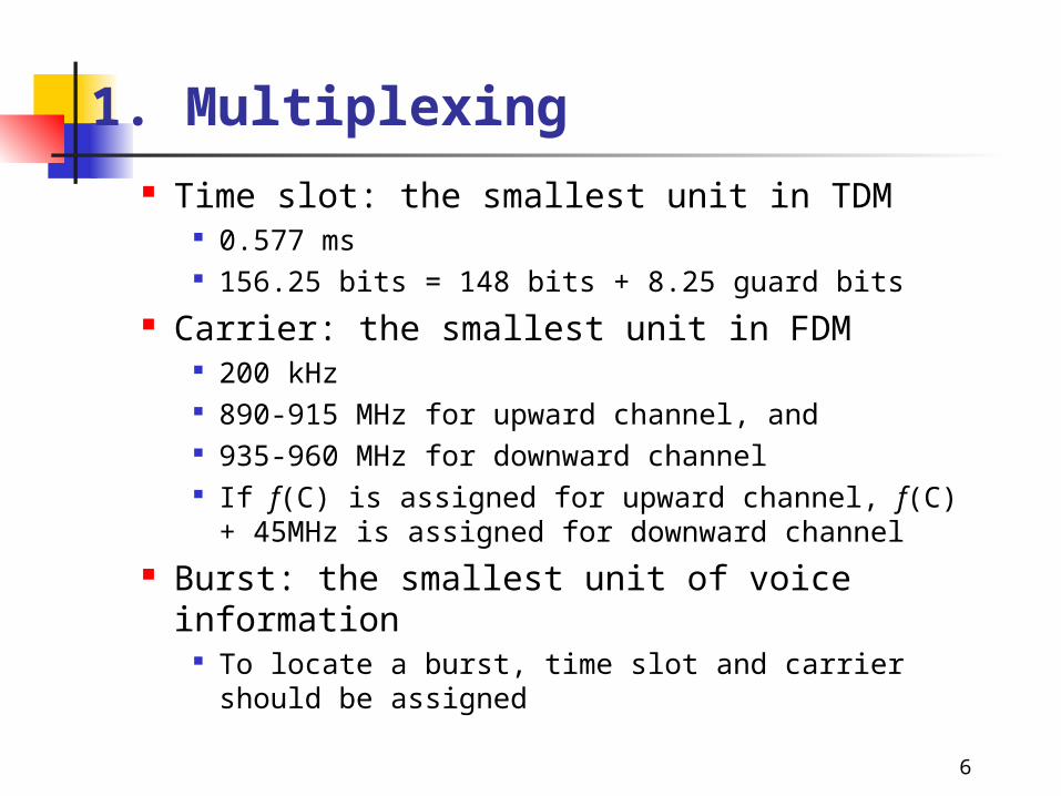
1. Multiplexing Time slot: the smallest unit in TDM
0.577 ms 156.25 bits = 148 bits + 8.25 guard bits
Carrier: the smallest unit in FDM 200 kHz 890-915 MHz for upward channel, and 935-960 MHz for downward channel If f(C) is assigned for upward channel, f(C) + 45MHz is
assigned for downward channel Burst: the smallest unit of voice information
To locate a burst, time slot and carrier should be assigned
7
1. Multiplexing Guard time (ramp time, tail) bits
To isolate one burst from another From time to turn on or off the transmitter To compensate different distance to the base station
Allowed power during a unit of burst p. 96
8
1. Multiplexing TDMA (Time Division Multiple Access)
TDMA takes the advantage of the pattern of human conversation Conversation between people has frequent periods of silence
p. 98 (Fig. 5-6)
1. Voice is digitized by A/D converter2. Digitized code is buffered at the mobile node3. TDMA system interleaves the digitized talkspurts of
multiple users across one channel Up to eight users can occupy the same frequency domain Signals are not interfere because they are put at a different
time domain and separated by guard time p. 97
9
1. Multiplexing
Statistical TDMA VAC (Voice Activity Compression): channel slots are
consumed during speaking only. VAD (Voice Activity Detector): senses voice data
flows into transmitting buffer. The requested slot is assigned about 40ms or denied.
If denied, the voice data is lost. Request and assignment procedure of Statistical TDM
p. 100
10
2. CDMA
Code division multiple access All users use a huge single spectrum of bandwidth.
Each signal is modulated (spread) across an entire band. Simultaneous users may interfere to each other.
The communication quality depends upon the amount of data transmitted, not how many channels are open.
That is, we don’t users who open connection without generating traffic.
Demultiplexing is done by orthogonal codes.
11
2. CDMA CDMA and language analogy
Suppose there are 2k persons in a bus. Two of each comes from the same country. All others comes from all k different countries which uses all
different languages. They talk to the other from the same country simultaneously. Even if the bus is very noisy, they can easily ignore others’
superfluous noise (voice), because they cannot understand the other language.
If 2k persons speak in a single language, they probably cannot hear the other’s voice.
Similarly, CDMA receiver easily filters out the other’s talk as well as noise.
12
2. CDMA
Code division 1 bit is coded into k-unit called chips.
Bandwidth reduces by k. Data is coded with code sequence.
13
2. CDMA Generation of code sequence
Regenerating function g, h: Definition: g(Xi, Ci) = Ci+1, h(Xi, Ci) = Xi+1
Xi, Xi+1, Ci, Ci+1 are k-chip words Xi, Xi+1 are not open to public, but Ci, Ci+1 are known. (they are transmitting signal(chips) to the air) One must know Xi to predict Ci
Operation X0 is assigned as an initial value at both transmitting and receiving
node. Use regenerating function until the same value repeats, in other word Find the smallest q that satisfies Cq = C0 (q>1) in the sequence: C0
C1 C2 … Cq = C0 Due to the property of generator function, 12 kq
14
2. CDMA Good security in CDMA system
Party A tries to send data to party B Everybody has the same generator function g(), but Only party A and B knows the code, and They are synchronously generate the code sequence.
Only party A and B knows the code sequence. All others have different code sequence.
Anybody except party A and B cannot correctly decode the transmitted data.
Hacking of code sequence without knowing code C0. To produce correct sequence, hackers have to know the state variable
X or, they have to execute the next.1. Record the total unit-cycle = (chips)2. Record the current k-bit( chips ) sequence. (call this S)3. Find out where S is located in the whole sequence
Step 1 and 3 is practically impossible k is very large in real system
kk 22k
15
2. CDMA
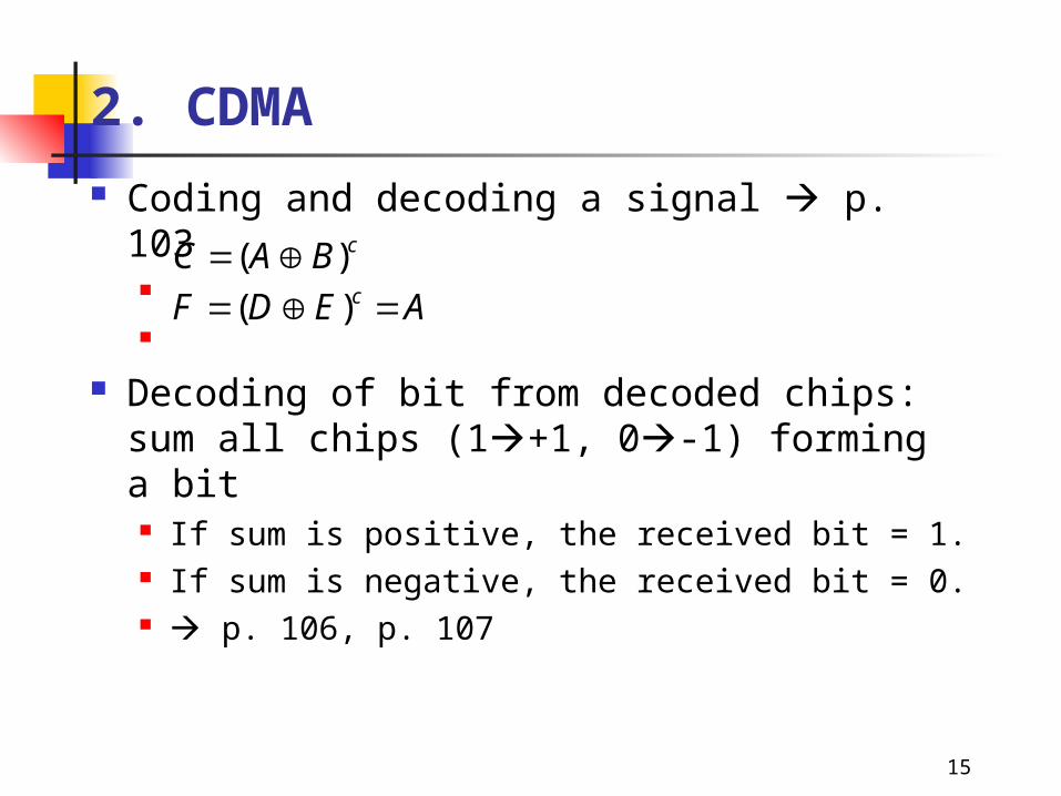
Coding and decoding a signal p. 103
Decoding of bit from decoded chips: sum all chips (1+1, 0-1) forming a bit If sum is positive, the received bit = 1. If sum is negative, the received bit = 0. p. 106, p. 107
cBAC )( AEDF c )(
16
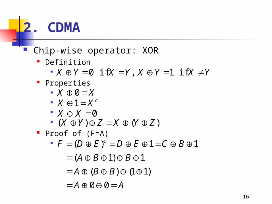
2. CDMA Chip-wise operator: XOR
Definition
Properties
Proof of (F=A)
YXYXYXYX if 1 , if 0
XX 0cXX 1
0 XX)()( ZYXZYX
AA
BBA
BBA
BCEDEDF c
00
)11()(
1)1(
11)(
17
2. CDMA
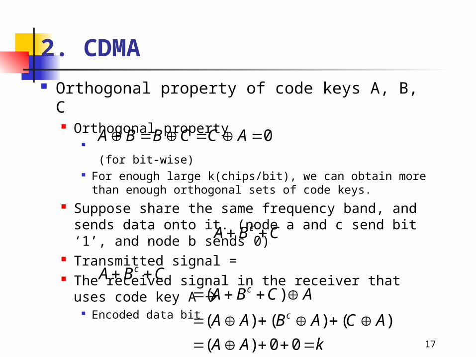
Orthogonal property of code keys A, B, C Orthogonal property
(for bit-wise) For enough large k(chips/bit), we can obtain more than enough
orthogonal sets of code keys. Suppose share the same frequency band, and sends data
onto it. (node a and c send bit ‘1’, and node b sends 0) Transmitted signal = The received signal in the receiver that uses code key A
Encoded data bit
0 ACCBBA
CBA c
CBA c
kAA
ACABAA
ACBAc
c
00)(
)()()(
)(
18
2. CDMA Similarly for transmission of general data, only data
encrypted with code key A is decrypted using the code key A.
The received data can easily ignore other’s communication But actually the more users sends data, the more interference
increases noise There is upper bound in the number of simultaneous
transmission.
19
2. CDMA
Direct sequence and frequency hopping Direct sequencing: (general method) all users share a
huge frequency band. Frequency hopping: a transmitter changes its carrier
frequency often. (currently not used) Sender and receiver have a common rule how to choose the
frequency in the unit of chips. Users may conflict a chip due to sharing of a frequency band.
p. 108
20
2. CDMA Comparison of AMPS(FDMA), TDMA, and CDMA
Complexity: FDMA < TDMA < CDMA Frequency efficiency (bit rate/allocated frequency): FDMA <
TDMA < CDMA p. 109 table
1. Total frequency band allocated to the mobile service2. Frequency reuse3. Frequency band allocated to a single channel4. Number of simultaneous RF channels = term 1 / term35. Number of RF channels per a cell (base station) = term 4 / term 26. Usable channels per cell7. Call per radio frequency8. Voice channel per cell = term 6 x term 7
21
3. Compression
Compression technique Shrink the size of digital data using statistical behavior
by Analog data:
Analyze the analog data and represent it numerically Choose major terms
Discrete data: Reduce the repeated terms or characters
Compression scheme depends upon the type of service e.g. a good compression scheme in voice does not guarantee
its performance in image compression.
22
3. Compression Voice compression technique
Vocoder: encoding scheme applied only to voice signal Currently most advanced technique can dive about 2k bps data rate
and Used as voice response system (off-line calculation)
Channel vocoder Waveform is processed into parameters that measure vocal
characteristics. Parameters represent the energy of voice signal from sub-band pass
filter. Encoding
An original signal is analyzed and find out the closest parameters. Calculated parameter set and send this set instead of analog voice signal.
Decoding From received parameter set, build (synthesize) voice signal
23
3. Compression LPC (Linear Prediction Coding)
Generally voice pattern lasts to pronounce a vowel or a consonant, and then jumps to the next one. Even in the transient period, it shows a habitual way of change.
With the input data collected so far, predict how the signal will change next.
Vector quantization p. 111 The pattern of a speech signal is defined in 20~50ms durations
(called speech segments or parcels) The segments are stored in a register in 6 PCM word blocks. Blocks are compared against a table of values (a codebook). The entry that is closest to the actual value is used as the
transmitted value.
24
3. Compression Data compression technique
Use variable-length characters instead of ASCII (fixed length). Frequently used characters (vowels, spaces) are given short length.
Bit mapping: a bit(or a word) is used to indicate compression will be done in following characters.
Run length encoding (Kermit): Repeated characters are represented by three bytes 1st byte: the next two bytes is not normal characters but run length
encoding. 2nd byte: number of repetition 3rd byte: repeated characters
Relative encoding For data that represents analog stream (symbol, graph)
Data is sampled at fixed in intervals. If the curve is smooth, two consecutive data is of similar value. If the curve shows sharp fluctuation, it may not be effective. (it may
lengthen data)
25
3. Compression
Fax compression Fax operation:
Data scanning Image on the paper is scanned vertically and horizontally. Output: electrical image are made of 0 and 1 (if white and
black). Encoding: shrink the output data size.
Run length encoding scheme Images coded as w/b runs (00000 or 1111 0:5 1:4)
Relative encoding scheme Only the changed part from previous line is coded. Effective if two adjacent lines are very alike.


![St. Xavier’s College – Autonomous Mumbai Syllabus For … schemes [TDMA, FDMA, CDMA] Separating uplink and downlink traffic GSM migration PDC migration Cdmaone migration M-Commerce](https://img.pdfslide.us/doc/110x75/5b3a8b1d7f8b9a1a678dbe06/st-xaviers-college-autonomous-mumbai-syllabus-for-schemes-tdma-fdma-cdma.jpg)