Embed Size (px)
Citation preview

Disclosure to Promote the Right To Information
Whereas the Parliament of India has set out to provide a practical regime of right to information for citizens to secure access to information under the control of public authorities, in order to promote transparency and accountability in the working of every public authority, and whereas the attached publication of the Bureau of Indian Standards is of particular interest to the public, particularly disadvantaged communities and those engaged in the pursuit of education and knowledge, the attached public safety standard is made available to promote the timely dissemination of this information in an accurate manner to the public.
इंटरनेट मानक
“!ान $ एक न' भारत का +नम-ण”Satyanarayan Gangaram Pitroda
“Invent a New India Using Knowledge”
“प0रा1 को छोड न' 5 तरफ”Jawaharlal Nehru
“Step Out From the Old to the New”
“जान1 का अ+धकार, जी1 का अ+धकार”Mazdoor Kisan Shakti Sangathan
“The Right to Information, The Right to Live”
“!ान एक ऐसा खजाना > जो कभी च0राया नहB जा सकता है”Bhartṛhari—Nītiśatakam
“Knowledge is such a treasure which cannot be stolen”
“Invent a New India Using Knowledge”
है”ह”ह
IS 15305-3 (2003): Natural Gas - Calculation of CompressionFactor, Part 3: Calculation Using Physical Properties [PCD3: Petroleum, Lubricants and their Related Products]


IS 15305 (Part 3) :2003ISO 12213-3:1997
Indian Standard
NATURAL GAS—CALCULATION OFCOMPRESSION FACTOR
PART 3 CALCULATION USING PHYSICAL PROPERTIES
ICS 75.060
@ BIS 2003
BUREAU OF INDIAN STANDARDSMANAK BHAVAN, 9 BAHADUR SHAH ZAFAR MARG
NEW DELHI 110002
Apr// 2003 Price Group 11
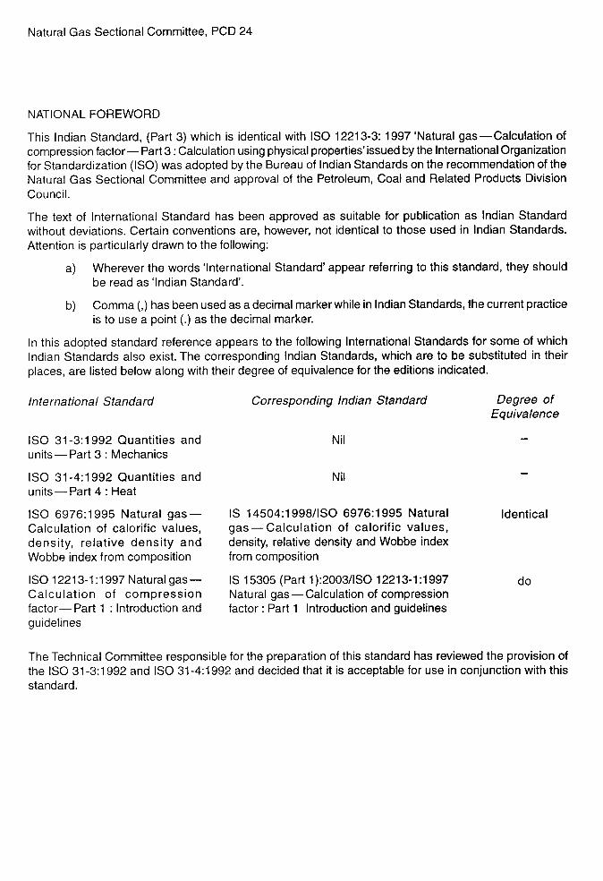
Natural Gas Sectional Committee, PCD 24
NATIONAL FOREWORD
This Indian Standard, (Part 3) which is identical with ISO 12213-3:1997 ‘Natural gas—Calculation ofcompression factor— Part 3: Calculation using physical properties’ issued by the International Organizationfor Standardization (ISO) was adopted by the Bureau of Indian Standards on the recommendation of theNatural Gas Sectional Committee and approval of the Petroleum, Coal and Related Products DivisionCouncil.
The text of International Standard has been approved as suitable for publication as Indian Standardwithout deviations. Certain conventions are, however, not identical to those used in Indian Standards.Attention is particularly drawn to the following:
a) Wherever the words ‘International Standard’ appear referring to this standard, they shouldbe read as ‘Indian Standard’.
b) Comma (,) has been used as a decimal marker while in Indian Standards, the current practiceis to use a point (.) as the decimal marker.
In this adopted standard reference appears to the following International Standards for some of whichIndian Standards also exist. The corresponding Indian Standards, which are to be substituted in theirplaces, are listed below along with their degree of equivalence for the editions indicated.
International Standard
ISO 31-3:1992 Quantities andunits — Part 3: Mechanics
ISO 31-4:1992 Quantities andunits—Part 4: Heat
ISO 6976:1995 Natural gas—Calculation of calorific values,density, relative density andWobbe index from composition
ISO 12213-1:1997 Natural gas—Calculation of compressionfactor— Part 1 : Introduction andguidelines
Corresponding Indian Standard Degree ofEquivalence
Nil
Nil
IS 14504:1998/1S0 6976:1995 Natural Identicalgas—Calculation of calorific values,density, relative density and Wobbe indexfrom composition
IS 15305 (Part 1):2003/1S0 12213-1:1997Natural gas —Calculation of compressionfactor: Part 1 Introduction and guidelines
do
The Technical Committee responsible for the preparation of this standard has reviewed the provision ofthe ISO 31-3:1992 and ISO 31-4:1992 and decided that it is acceptable for use in conjunction with thisstandard.
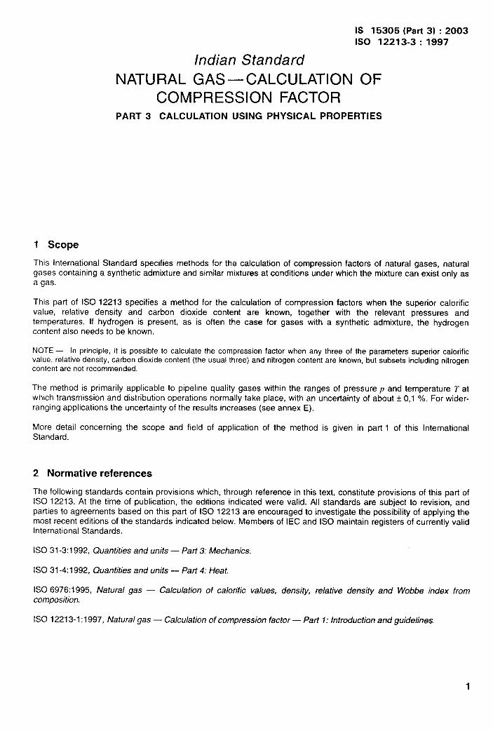
IS 15305 (Part 3) :20031s0 12213-3:1997
Indian Standard
NATURAL GAS—CALCULATION OFCOMPRESSION FACTOR
PART 3 CALCULATION USING PHYSICAL PROPERTIES
1 Scope
This International Standard specifies methods for the calculation of compression factors of natural gases, naturalgases containing a synthetic admixture and similar mixtures at conditions under which the mixture can exist only asa gas.
This part of ISO 12213 specifies a method for the calculation of compression factors when the superior calorificvalue, relative density and carbon dioxide content are known, together with the relevant pressures andtemperatures. If hydrogen is present, as is often the case for gases with a synthetic admixture, the hydrogencontent also needs to be known.
NOTE — In principle, it is possible to calculate the compression factor when any three of the parameters superior calorificvalue, relative density, carbon dioxide content (the usual three) and nitrogen content are known, but subsets including nitrogencontent are not recommended.
The method is primarily applicable to pipeline quality gases within the ranges of pressure p and temperature T atwhich transmission and distribution operations normally take place, with an uncertainty of about * 0,1 ‘A. For wider-ranging applications the uncertainty of the results increases (see annex E).
More detail concerning the scope and field of application of the method is given in part 1 of this InternationalStandard.
2 Normative references
The following standards contain provisions which, through reference in this text, constitute provisions of this part ofISO 12213. At the time of publication, the editions indicated were valid. All standards are subject to revision, andparties to agreements based on this part of ISO 12213 are encouraged to investigate the possibility of applying themost recent editions of the standards indicated below. Members of IEC and ISO maintain registers of currently vaiidInternational Standards.
ISO 31-3:1992, Quantities and units — Part 3: Mechanics.
ISO 31-4:1992, Quantities and units — Part 4: Heat.
ISO 6976:1995, Natural gas — Calculation of calorific values, density, relative density and Wobbe index fromcomposition.
ISO 12213-1:1997, Natural gas — Calculation of compression factor — Pari 1: Introduction and guidelines.
1
IS 15305 (Part 3) :2003ISO 12213-3:1997
3 Definitions
All definitions relevant to the use of this part of ISO 12213 are given in part 1.
4 Method of calculation
4.1 Principle
The method recommended uses equations which are based on the concept that pipeline quality natural gas may beuniquely characterized for calculation of its volumetric properties by an appropriate and distinctive set of measurablephysical properties. These characteristics, together with the pressure and temperature, are used as input data forthe method.
The method uses the following physical properties: superior calorific value, relative density and carbon dioxidecontent. The method is particularly useful in the common situation where a complete molar composition is notavailable, but may also be preferred for its relative simplicity. For gases with a synthetic admixture, the hydrogencontent needs to be known.
4.2 The SGERG-88 equation
The calculation method using physical properties is based on the standard GERG 88 (SGERG-88) virial equationfor natural gases [11, [21, [3]. The standard GERG 88 virial equation is derived from the master GERG 88(MGERG-88) virial equation, which is a method of calculation based on a molar-composition analysis [41.
The SGERG-88 virial equation from which the compression factor z is calculated may be written as
Z=l+-B~+Cp~ . ..(1)
where
B and c are functions of the input data comprising the superior calorific value Hs, the relative density d, thecontents of both inert and combustible non-hydrocarbon components of the gas mixture (C02 and H2)and the temperature T,
Pm is the molar density given by
Pm = P/(zW . ..(2)
where
Z =fl ~, T, Hs, ~, XC027XHZ) (3)
However, the SGERG-88 method treats the natural-gas mixture internally as a five-component mixture consisting ofan equivalent hydrocarbon gas (with the same thermodynamic properties as the sum of the hydrocarbons present),nitrogen, carbon dioxide, hydrogen and carbon monoxide. To characterize the thermodynamic properties of thehydrocarbon gas adequately, the hydrocarbon heating value HcH k also needed. Therefore, the calculation of Zuses
~ = fz (p, T, Hw, XCH,XN2,XC02, XHZ,XCO) . . . (4)
In order to be able to model coke oven gas mixtures, the mole fraction of carbon monoxide is taken to have a fixedrelation to the hydrogen content. If hydrogen is not present (XH2 < 0,001), then set XH2 = O. The natural-gas mixtureis then treated in the calculation method as a three-component mixture (see annex B).
The calculation is performed in three steps,
First, the five-component composition from which both the known superior calorific value and the known relativedensity can be calculated satisfactorily may be found from the input data by an iterative procedure described indetail in annex B.
2
IS 15305 (Part 3) :2003ISO 12213-3:1997
Secondly, once this composition is known, B and C may be found using relationships also given in annex B.
In the third step, equations (1) and (2) are solved simultaneously for pm and Z by a suitable numerical method.
A flow diagram of the procedure for calculating Z from the input data is shown in figure B.1.
4.3 Input variables
4.3.1 Preferred input data set
The input variables required for use with the SGERG-88 equation are the absolute pressure, temperature andsuperior calorific value (volumetric basis), the relative density, the carbon dioxide content and the hydrogen content.Thus the physical properties used the input data set (set A) are
Hs, d, XC02 and XH2
Relative density is referred to normal conditions (101 ,325 kPa and O “C) and superior calorific value is referred tonormal conditions (101 ,325 kPa and O ‘C) and a combustion temperature of 25 ‘C.
4.3.2 Alternative input data sets
Three alternatives to the preferred input data set (see 4.3.1) may be used with the standard GERG virial equation:
xN21XC021d and xH2 (set C)
~N21xco2~ HS and xHz (set D)
The alternative input data sets are considered fully in GERG Technical Monograph TM5 [31. Use of the alternativeinput data sets gives results which may differ at the foutth decimal place. This part of ISO 12213 recommends theuse of input data set A.
4.4 Ranges of application
4.4.1 Pipeline quality gas
The ranges of application for pipeline quality gas are as defined below:
absolute pressure O MPa s p < 12MPa
temperature 263K ST s 338 K
mole fraction of carbon dioxide O < xc@ <0,20
mole fraction of hydrogen o ~ .++2 = 0,10
superior calorific value 30 MJm-a < HS s 45 MJm-3
relative density 0,55 Gd < 0,80
The mole fractions of other natural-gas components are not required as input. These mole fractions shall, however,lie within the following ranges:
methane 0,7 ==XcHq S 1,0
nitrogen O < XN2 s 0,20ethane t) < Xc*HG s 0,10
propane o s xC3HE s 0,035
butanes o = -~C4HIo<01015
IS 15305 (Part 3) :2003ISO 12213-3:1997
pentanes O < ‘~sHIP < 0,005
hexanes o < XC6 ==0,001
heptanes o = xc, s 0,0005
octanes plus higher hydrocarbons o < XC8+ = 0,0005
carbon monoxide o G Xco s 0,03
helium O < .XH~ <0,005
water 0 = XH20 <0,00015
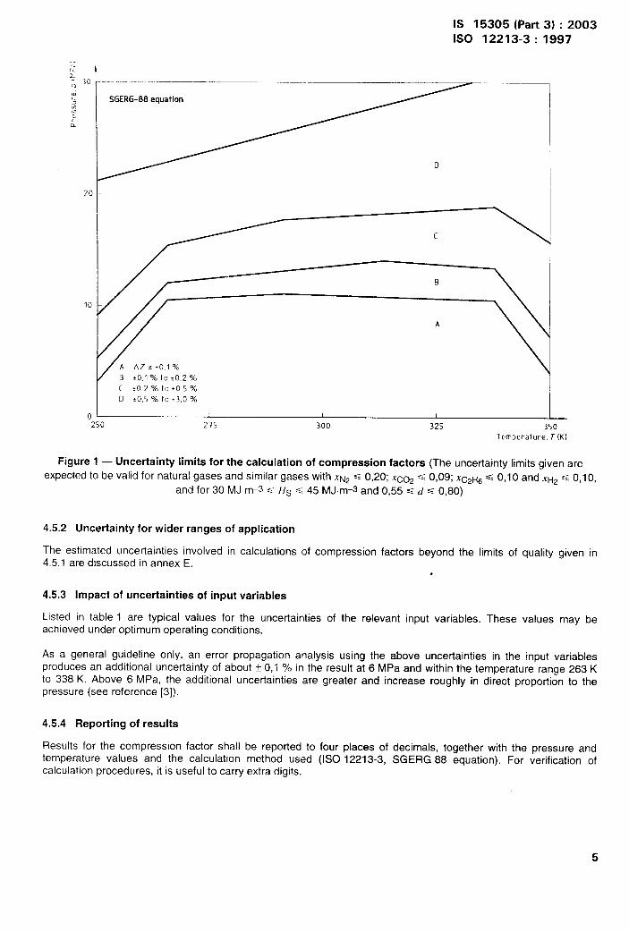
The method applies only to mixtures in the single-phase gaseous state (above the dew point) at the conditions oftemperature and pressure of interest. For pipeline quality, the method is applicable over wider ranges oftemperature and pressure but with increased uncertainty (see figure 1). In the computer implementation, the lowertemperature limit is set at 250 K.
4.4.2 Wider ranges of application
The ranges of application tested beyond the limits given in 4.4.1 are:
absolute pressure O MPa <f s 12MPa
temperature 263K ST s 338 K
mole fraction of carbon dioxide O ==XC02 ==0,30mole fraction of hydrogen o < XH2 s 0,10
superior calorific value 20 MJ. m-3 s Hs s 48 MJ. m–3
relative density 0,55 Gd <0,90
The allowable mole fractions of other major natural-gas components are extended to:
methane 0,5 ==.XcH4 <1,0
nitrogen 0 = XN2 <0,50
ethane O = XczHGs 0,20
propane O = .Xc31+8c 0,05
The limits for other minor natural-gas components remain as given in 4.4.1 for pipeline quality gas.
The method is not applicable outside these ranges; the computer implementation described in annex B will not allowviolation of the limits of composition quoted here.
4.5 Uncertainty
4.5.1 Uncertainty for pipeline quality gas
The uncertainty in the prediction of the compression factor AZ (for the temperature range 263 K to 338 K) is i 0,1 Y.at pressures up to 10 MPa and t 0,2 O/. between 10 MPa and 12 MPa for natural gases with XNPs 0,20,
XC02 ~ 0!09! Xc2HGs 0,10 and XH2 SS 0,10, and for 30 MJ.m-3s H.s <45 MJ.m-3 and 0,55s ds 0,80, (seefigure 1).
For gases with a C02 content exceeding 0,09, the uncertainty of ~ 0,1 % is maintained for pressures up to 6 MPaand for temperatures between 263 K and 338 K. This uncertainty level is determined by comparison with the GERGdatabank on measurements of the compression factor for natural gases [s1,[61and with the Gas Research Institutedata [91.
4
IS 15305 (Part 3) :2003ISO 12213-3:1997
SGERG-88equation
D
B fO,l 7. to *0,2 %c to 2 % to 10,5‘%D :0,5 % to 13,0%
—250 275 300 325 350
Temperature, T (K)
Figure 1 — Uncertainty limits for the calculation of compression factors (The uncertainty limits given are
expected to be valid for natural gases and similar gases with XN2s 0,20; IC02 s 0,09; XcP1.+~s 0,10 and XH~s 0,10,
and for 30 MJ m-s < Hs s 45 MJm-3 and 0,55< d = 0,80)
4.5.2 lJncertainty for wider ranges of application
The estimated uncertainties involved in calculations of compression factors beyond the limits of quality given in4.5.1 are discussed in annex E.
.
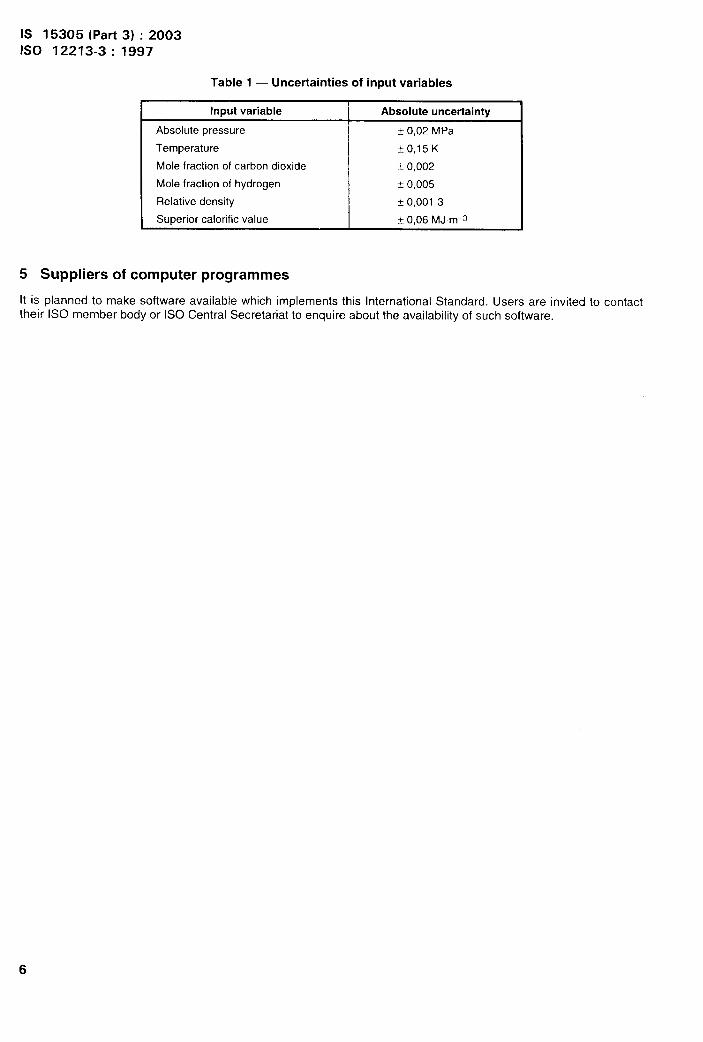
4.5.3 Impact of uncertainties of input variables
Listed in table 1 are typical values for the uncertainties of the relevant input variables. These values may beachieved under optimum operating conditions.
As a general guideline only, an error propagation analysis using the above uncertainties in the input variablesproduces an additional uncertainty of about t 0,1 % in the result at 6 MPa and within the temperature range 263 Kto 338 K, Above 6 MPa, the additional uncertainties are greater and increase roughly in direct proportion to thepressure (see reference [3]).
4.5.4 Reporting of results
Results for the compression factor shall be reported to four places of decimals, together with the pressure andtemperature values and the calculation method used (ISO 12213-3, SGERG 88 equation). For verification ofcalculation procedures, it is useful to carry extra digits.
5
IS 15305 (Part 3) :2003ISO 12213-3: 1997
Table 1 — Uncertainties of input variables
Input variable I Absolute uncertainty
Absolute pressure i 0,02 MPa
Temperature +r),15K
Mole fraction of carbon dioxide i o,oclz
Mole fraction of hydrogen f 0,005
Relative density + 0,001 3
Superior calorific value I O,r)(jMJ.m-3
5 Suppliers of computer programmed
It is planned to make software available which implements this International Standard. Users are invited to contacttheir ISO member body or ISO Central Secretariat to enquire about the availability of such software.
IS 15305 (Part 3) :20031s0 12213-3:1997
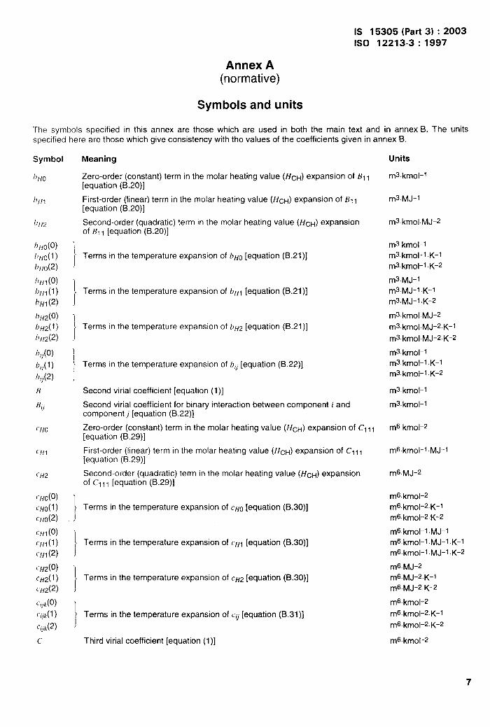
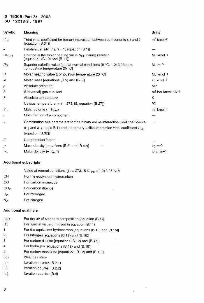
Annex A(normative)
Symbols and units
The symbols specified in this annex are those which are used in both the main text and in annex B. The unitsspecified here are those which give consistency with the values of the coefficients given in annex B.
Symbol
/),{()
/)/{1
/)[/2
l)f{o(o)
b~o(l)
1)/{0(2)
1?},1(o)
b~l(l)
b“l (2)
121,2(0)bff2(1)
bH&’)
b,,(0)
17,,(1)
fJ,,(2)
u
B,,
Clfo
(’HI
~ff2
~/fo(0)
~HO(l )
~HO(2)
~H~(0)
CHI(l)
~Hl (2)
CH2(0)
CH2(1 )
~H2(2)
C[]k(o)
~l,k(l )
Cqk(z)
c
Meaning
Zero-order (COnSkint) term in the molar heating value (HcH) eXpanSiOn of BI I[equation (B.20)]
First-order (linear) term in the molar heating value ([#cH) expansion of III I[equation (B.20)]
Second-order (quadratic) term in the molar heating value (HcH) expansionof B11 [equation (B.20)]
ITerms in the temperature expansion of bHO[equation (B.21)]
ITerms in the temperature expansion of bF{l [equation (B.21 )]
1
tTerms in the temperature expansion of bHz [equation (B.21 )]
1Terms in the temperature expansion of b,, [equation (B.22)]
Second virial coefficient [equation (1)]
Second virial coefficient for binary interaction between component i andcomponent [equation (B.22)]
Zero-order (constant) term in the molar heating value (HcH) expansion of Cl 11[equation (B.29)]
First-order (linear) term in the molar heating value (HcH) expansion of Cl 11[equation (B.29)]
Second-order (quadratic) term in the molar heating value (HcH) expansionof Cl 11 [equation (B.29)]
1Terms in the temperature expansion of CHO [equation (B.30)]
J
}Terms in the temperature expansion of CH1 [equation (B.30)]
}Terms in the temperature expansion of CH2 [equation (B.30)]
}Terms in the temperature expansion of CU[equation (B.31 )]
Third virial coefficient [equation (1)]
Units
m3.kmOl–l
m3.MJ-l
m3.kmOl. MJ-2
m3.kmOl–l
m3.kmOl-l .K-l
m3.kmol-1 K-2
m3. MJ-l
m3.MJ-l K-l
m3.MJ-l .K-2
m3.kmOl.MJ–2
m3. kmOl.MJ-2.K-l
m3.kmOl.MJ-2. K-2
m3.kmOl–l
m3.kmOl-l .K–l
m3.kmOl-l .K-2
m3.kmOl-l
m3.kmOl-l
m6.kmOl-2
m6.kmOl-l. MJ-l
m6.MJ-2
m6.kmOl–2
m6. kmOl-2. K-l
m6.kmO1-2.K-2
m6.kmOl-l .MJ-1m6.kmOl-l .MJ-1 .K-l
m6. kmOl-l .MJ-I .K-2
m6. MJ-2
m6. MJ-2. K-l
n-16.MJ-2. ~-2
m6.kmOl–2
m6.kmOl-2. K-l
m6.kmOl–2.K-2
m6. kmO[–2
7
w II
IS 15305 (Part 3) :2003ISO 12213-3: 1997
Meaning
Third virial coefficient for ternary interaction between components i, j and k
[equation (B.31 )]
Relative density [d(air) = 1; equation (B.1 )]
Change in the molar heating value F{cH during iteration[equations (B.1 O) and (B.11 )]
Superior calorific value [gas at normal conditions (O “C, 1,01325 bar),combustion temperature 25 “C]
Molar heating value (combustion temperature 25 ‘C)
Molar mass [equations (B.5) and (B.8)]
Absolute pressure
(Universal) gas constant
Absolute temperature
Celsius temperature [= T - 273,15; equation (B.27)]
Molar volume (= I/pm)
Mole fraction of a component
Combination rule parameters for the binary unlike-interaction virial coefficients
B12 and B13 (table B.1) and the ternary unlike-interaction virial coefficient C,,k
[equation (B.32)]
Compression factor
Mass density [equations (B.8) and (B.42)] .
Molar density (= Vm-l)
Additional subscripts
n Value at normal conditions (Tn = 273,15 K, pn = 1,01325 bar)
CH For the equivalent hydrocarbon
co For carbon monoxide
C02 For carbon dioxide
H2 For hydrogen
N2 For nitrogen
Additional qualifiers
(air)
(D)
1
2
3
4
5
(id)
(1A)
(,’)
(),)
For dry air of standard composition [equation (B.1)]
For special value of p used in equation (B.11 )
For the equivalent hydrocarbon [equations (B.12) and (B.1 5)]
For nitrogen [equations (B.12) and (B.1 6)]
For carbon di~xide [equations (B.12) and (B.1 7)] -
For hydrogen [equations (B.12) and (B.1 8)]
For carbon monoxide [equations (B.12) and (B.1 9)]
Ideal gas state
Iteration counter (B.2.1)
Iteration counter (B.2.2)
Iteration counter (B.4)
Units
m6.kmOl-2
—
MJ kmol-1
MJm-s
MJkmol-1
kgkmol-1
bar
m3 bar.krnol-l K-l
K
“c
m3. kmOl–l
—
—
—
kg.n--3
kmolm-s
8

IS 15305 (Part 3) :20031s0 12213-3:1997
Annex B(normative)
Description of the SGERG-88 method
This annex gives the equations for and numerical values of coefficients which together specify completely theSGERG method for calculation of compression factors,
It also describes iteration procedures adopted by GERG [31for implementing the method in the verified Fortran 77subroutine SGERG.FOR. This subroutine provides the correct solution; other computational procedures areacceptable provided that they can be demonstrated to yield identical numerical results. The calculated results shallagree to at least the fourth place of decimals with the examples given in annex C.
Other implementations which are known to produce identical results are as follows:
a) A Basic version, described In GERG TM5 [3], which may be used with a variety of metric reference conditions.TkIk programme was designed “mainly for PC applications.
b) A version in C, described in German DVGW Directives, sheet G486 [81.
c) A version in Turbo Pascal.
,411these programmes have been verified to give the same results to within 10-5. The availability of the programmesand the conditions which apply to their use are discussed in part 1 of this International Standard.
6.1 Basic structure of the calculation method
As described in 4.2, the calculation proceeds in three steps, which are shown schematically in figure B. 1.
b-------— —1
>-lCaLcu[ate intermediate data:
e,,.X(O X[H(U)XN2(U)He.(;)IYf.(u) Q,,(u). 8.(V), pm”(v), lf~(v)
~
Ca[cuLate vlria[ coefficients:
+ -—--——— —1
So[ve viria~ equation!
z=l+8Qm (r, p,x, )+c@m2(T,p, x,) –..J
(see ctause B.4)
Figure B.1 — Flow diagram for standard GERG-88 calculation method(r, = mole fraction of component i)

IS 15305 (Part 3) :2003ISO 12213-3:1997
The calculation is described below in the order in which these three steps are carried out.
Step I
The input data are pressure, temperature, gross calorific value, relative density and the mole fractions of carbondioxide and hydrogen. If the values of the first three parameters are in any units other than bar, “C and MJ/m3, theyshall first be converted precisely to values in bar, ‘C and MJ/m3, respectively, using the guidelines set out inannex D.
The input data are then used to calculate the following intermediate data:
Mole fraction of:
hydrocarbon gas
nitrogen
carbon monoxide
Molar heating value of the equivalent hydrocarbon
Molar mass of the equivalent hydrocarbon
Second virial coefficient(Tn=273,15 K)
Molar density at normal conditions
Mass density at normal conditions
Superior calorific value of the gas
XCH
XN2X(xj
HcH
McH
Bn
Pm,n
Pn
Hs
In equations (B.1 ) to (B.46), each symbol represents a physical quantity divided by its selected unit (see annex A),such that their quotient is the dimensionless value of the quantity.
Step II
The intermediate data are used to calculate the second and third virial coefficients for the natural gas at the requiredtemperature@, B(~,HcH,Xi) and C(T,HcH,X,).
Step 111
The second and third virial coefficients determined in the second step are inserted in the virial equation, and thecompression factor Z is calculated for a given pressure and temperature.
The symbols used are defined in annex A.
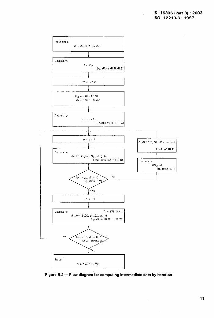
B.2 Calculation of intermediate data
The eight intermediate-data values (XCH,XN2,xco, HCH, MCH, Bn, prn,n, pn) are determined from equations (B.1 ) to(B.8) using the iterative method presented in figure 9.2. Values of the constants used in these equations are givenin table B.1.
A = d~ (air) ... (B.1)
Xco = 0,0964 xH2 . . . (B.2)
Vm,n(id) = RT. /p. . . . (B.3)
Pm,n(v) = [Vm,n(d + Bn(v)]-’ . . . (B.4)
10
IS 15305 (Part 3) :20031s0 12213-3:1997
Input data:
p, t, /f~, d, XLOZ,XH2
1[a(culate:
p“, xcoEquations (B.1), (B.2)
r1
1
I ~=o,~=o I
It
I
I HCH(U = o) =10008.(v=O) = - 0,06S I
CaLcuLate:
pm. (v=O)Equations (B.3), (B.4)
CaLcuLate:
Xc},(u), x~~lul, M[JU), p,)(u)Equations (B.S) to (B.8)
+Yes
V=v.1
No
IResuLt:
‘[H. ‘N2.‘[O.~CH
Figure B.2 — Flow diagram for computing intermediate data by iteration
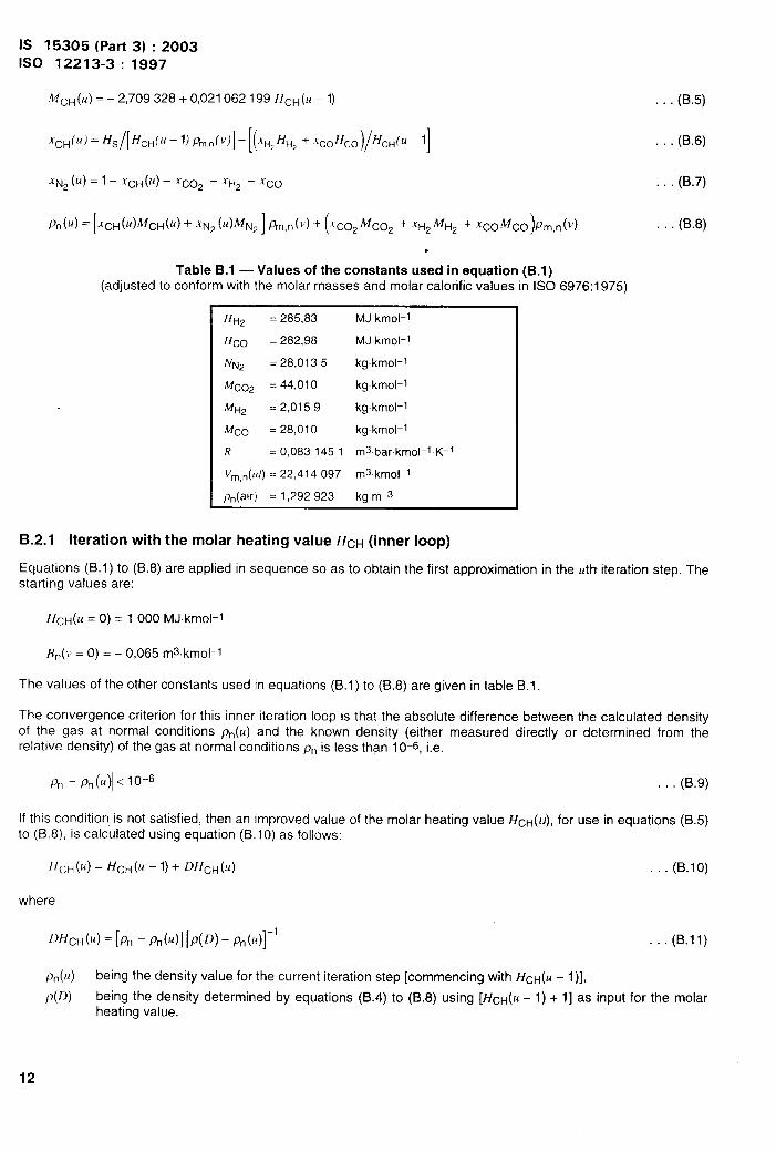
IS 15305 (Part 3) :2003ISO 12213-3: 1997
Mc~(It) = -2,709 328+ 0,021062199 HCH(U - 1)
‘~H(”)=~~/[~i~~( ~-l) P~,”(v)]-[(~H,~”, +.rcoHco)/Hc~(u -l]
~N2(U) = 1– XC~(U) – X@ – XH2 – Xco
)A(u) = [XCH(U)~CH(U) + -1N2 (U)MN2 ] %,n(v) + (I”C02 ~C02 + XH2 ~H2 + XCO~CO Pm,n(v)
●
Table B.1 — Values of the constants used in equation (B.1)(adjusted to conform with the molar masses and molar calorific values in ISO 6976:1 ‘375)
. . . (B.5)
(B.6)
. . (B.7)
. . . (B.8)
HH2 = 285,83
Hco = 282,98
NM = 28,0135
MC02 = 44,010
1%2 =2,0159
It’l’co = 28,010
R = 0,0831451
Vm,n(Id) = 22,414097
pn(air) = 1,292923
MJkmol-1
MJ kmol-1
kgkmol-1
kgkmol-1
kgkmol-1
kgkmol-1
ms.bar.kmol-l. K-l
ms kmol-1
kg m-s
B.2.I Iteration with the molar heating value ~cH (inner loop)
Equations (B.1 ) to (B.8) are applied in sequence so as to obtain the first approximation in the utkr iteration step. Thestarting values are:
}{CH(U = O) = 1000 MJkmol-1
Bn(v = O) = – 0,065 rns.krnol-l
The values of the other constants used in equations (B.1 ) to (B.8) are given in table B.1.
The convergence criterion for this inner iteration loop is that the absolute difference between the calculated densityof the gas at normal conditions pn(u) and the known density (either measured directly or determined from therelative density) of the gas at normal conditions pn is less than 10-6, i.e.
l% - Pn(u)l <10-6 . . . (B.9)
If this condition is not satisfied, then an improved value of the molar heating value ~cH(u), for use in equations (B.5)to (B.8), is calculated using equation (B.1 O) as follows:
//cH(u) = ffcH(u – 1)+ ~~cH(u) . . (B.1O)
where
~~~cH(u) = [% - ~n(u)] [~(~~) - ~n(u)]-’ . . (B.11)
Pn(u) being the density value for the current iteration step [commencing with HCH(U - l)],
p(D) being the density determined by equations (B.4) to (B.8) using [~CH(U – 1)+ 1]as input for the molarheating value.
12
IS 15305 (Part 3) :2003ISO 12213-3:1997
When the left-hand side of equation (B.9) is less than 10-6, this iteration loop is terminated and iteration with thesecond virial coefficient begins.
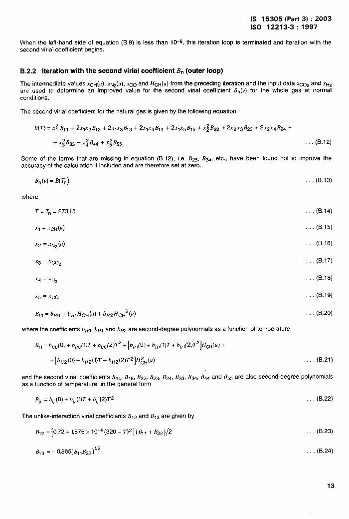
B.2.2 Iteration with the second virial coefficient Bn(outer loop)
The intermediate values XcH(U), Xp.j2(U), xco and ~cH(U) frOm the preceding iteratiOn and the inPUt data XC02 and XH~are used to determine an improved value for the second virial coefficient Bn(v) for the whole gas at normalconditions.
The second virial coefficient for the natural gas is given by the following equation:
B(T) = X; B11 + 2X1X2B12 + 2X1X3B13 + 2XIX4B14 + 2XIx5B15 + x$B22 + 2x2x3B23 + 2x2x4B24 +
+ x;B33 + x; B44 + x;B55 . . . (B.12)
Some of the terms that are missing in equation (B.12), i.e. B25, B34, etc., have been found not to improve theaccuracy of the calculation if included and are therefore set at zero.
Bn(v) = B(Tn) (B.13)
where
T = Tn = 273,15 . . . (B.14)
Xl = XCH (U) . . . (B.15)
X2 = xN2 (U) . . . (B.16)
x3 = XC02 . . (B.17)
X4 = XH2 (B.18)
x5 = Xco (B.19)
B,, = b“~+bf,,~cH(u) + b@cH2(f4 . (B.20)
where the coefficients bHo, bH1 and bH2 are second-degree polynomials as a function of temperature
B1l = bHO(0) + bHOI’l)T + bHo(2)T2 + [b~l(O,J+ b~l(l)T + ~H1(p)T2]~cH(u) +
+ [bH2(0) + bH2(l)T + b~2(2)T2 ]H~H(u) . . . (B.21)
and the second virial coefficients B14, BIs, B2~, B23, B24, B33, B34, B44 and BM are also second-degree polynomialsas a function of temperature, in the general form
Bti = bu (0) + bti (I)T + b. (2)T2 . . . (B.22)
The unlike-interaction virial coefficients B12 and B1s are given by
B12 = [0,72+ 1,875X 10-5(320 - T)*] (q, + B22)/2 . . . (B.23)
B, ~ = - 0,865(B1 ,B33 )1’2 . . . (B.24)
13
IS 15305 (Part 3) :2003ISO 12213-3:1997
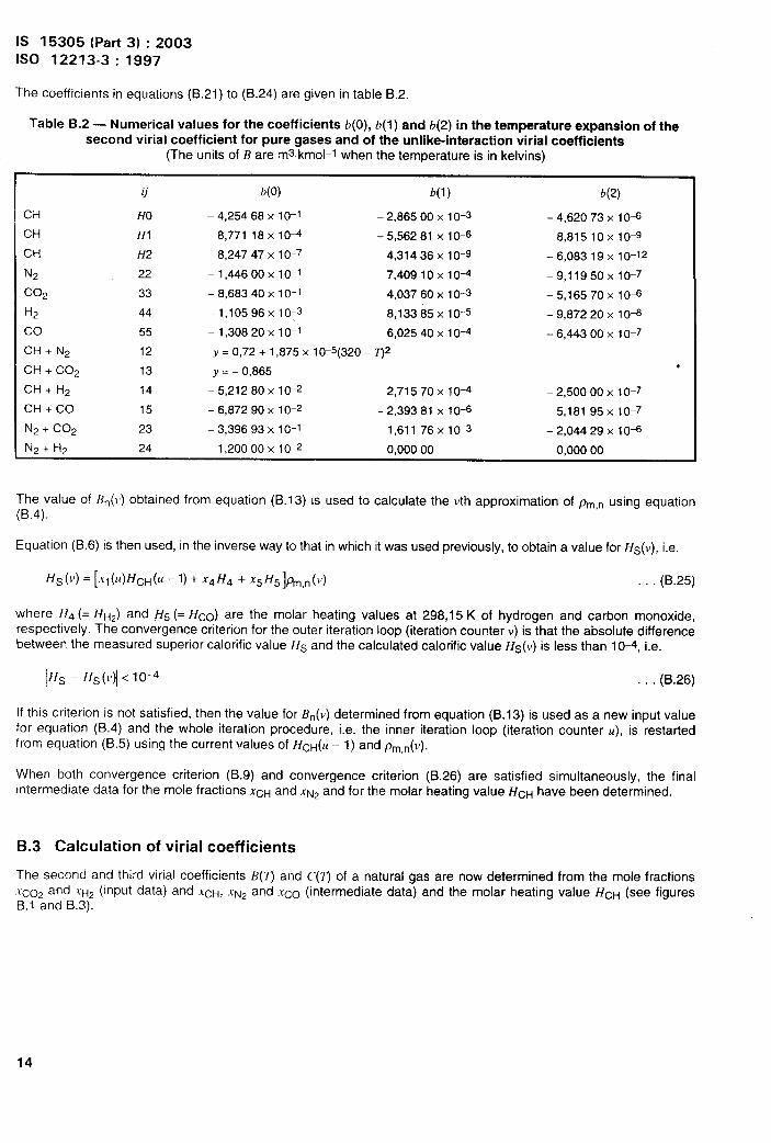
The coefficients in equations (B.21) to (B.24) are given in table B.2.
Table B.2 — Numerical values for the coefficients b(0), b(l)and b(2) in the temperature expansion of thesecond virial coefficient for pure gases and of the unlike-interaction virial coefficients
(The units of B are rnskmol-1 when the temperature is in kelvins)
CH
CH
CH
N2
co*H2
coCH + N2
cl-l+ co*CH + H2
CH + CO
N2 + C02
ti
HO
HI
H2
22
33
44
55
12
13
14
15
23
b(0)
– 4,254 68X 10-1
8,771 18X 10-4
-8,247 47X 10-7
—1,44600 X 10⁻¹
– 8,68340 X 10⁻¹
–1,10596x1O-3
– 1,308 20X 10-1
Y= 0,72 + 1,875 X 10-5(320 –
Y = -0,865
– 5,21280 X 10⁻²
-6,872 90X 10-2
-3,396 93X 10-1
b(1)
– 2,86500 X 10⁻³
– 5,56281 X 10⁻⁶
4,31436 X 10⁻⁹
7,40910 x 10⁻⁴
4,037 60X 10-3
8,13385 x1 O-5
6,025 40X 10-4
W
2,71570 X 10⁻⁴
– 2,39381 X 10⁻⁶
1,611 76x1 O-3
b(2)
– 4,620 73X 1o-I3
8,8151 OX IO-9
–6,083 19x 10-12
–9,1195OX1O-7
–5,165 70x 10-6
-9,87220 X 10⁻⁶
– 6,44300 X 10⁻⁷
*
-2,500 00X 10-7
5,181 95x1 O-7
– 2,04429X 10⁻⁶
N2 + H2 24 1,200 00x 10-2 0,00000 0,00000
The value of Bn(t) obtained from equation (B.13) is used to calculate the vth approximation of pm,n using equation(B.4),
Equation (B.6) is then used, in the inverse way to that in which it was used previously, to obtain a value for Hs(v), i.e.
H~ (V) = [X, (U) Hc~(U – 1)+ X4H4 + X5 H5]~,n(V) . . . (B.25)
where H4 (= ~H*) and ~5 (= Fico) are the molar heating values at 298,15 K of hydrogen and carbon monoxide,respectively. The convergence criterion for the outer iteration loop (iteration counter V) is that the absolute differencebetween the measured superior calorific value Hs and the calculated calorific value Hs(v) is less than 10-4, i.e.
/Hs - Hs(v)[ <10-4 . . . (B.26)
If this criterion is not satisfied, then the value for En(v) determined from equation (13.13) is used as a new input valuefor equation (B.4) and the whole iteration procedure, i.e. the inner iteration loop (iteration counter u), is restartedfrom equation (B.5) using the current values of HcH(u -1 ) and pm,n(v).
When both convergence criterion (B.9) and convergence criterion (B.26) are satisfied simultaneously, the finalintermediate data for the mole fractions XCHand XN2and for the molar heating value HcH have been determined.
6.3 Calculation of virial coefficients
The second and third virial coefficients B(T) and C(T) of a natural gas are now determinedXco2 and XH2 (input data) and XcH, XNz and ,r~o (intermediate data) and the molar heatingB.1 and B.3).
from the mole fractionsvalue HcH (see figures
14
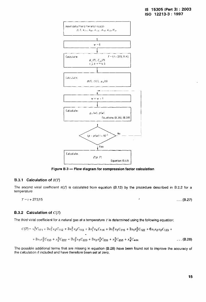
IS 15305 (Part 3) :2003ISO 12213-3:1997
I IInput data (third iteration Loop):
p,t, xcll, xN7, xco>. x~2, x[O, H[M
,
t! I
I ~=o IL
CalcuLate: T=(t+2?’3.15K)
8,,(T). C,,,(T)i,j, k=lto3
tI I
Ca\cuiate.B(r), C(T), pm(o)
1 IIk -–—-–-
ICaLcu(ate:
@m(w), p(w)
I Equations (B.313), (B.39) II I
I
o NoIP-P(W)I.10”5
‘ Yes
[aLcuLate:
Z(P, T)Equation (B.41)
Figure B.3 — Flow diagram for compression factor calculation
6.3.1 Calculation of l?(~
The second virial coefficient B(7) is calculated from equation (B.12) by the procedure described in B.2.2 for atemperature
T=r +273,15 # . . . (B.27)
6.3.2 Calculation of C(~
The third virial coefficient for a natural gas at a temperature T is determined using the following equation:
C(T) = X;C1ll + 3xf X&I12 + 3X: X3C113 + 3XfX4CI14 + 3XfX5Cl15 + 3X@122 + 6X1X2X3C123 +
-+3x1x; Cl 33 + x:C222 + 3X~X&23 + 3X2X&33 + x:c333 + X:ew . . . (B.28)
The possible additional terms that are missing in equation (B.28) have been found not to improve the accuracy ofthe calculation if included and have therefore been set at zero.
15
(B.29)
IS 15305 (Part 3) :2003ISO 12213-3: 1997
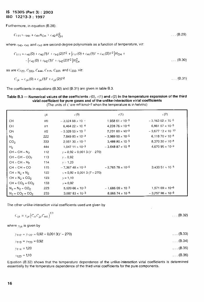
Furthermore, in equation (B.28):
Cl q, = cHo + CHIHCH + cwH~H
where ~Ho, CH1and ~H2 are second-degree polynomials as a function of temperature, viz:
C’l,, = cHo(0) + CHo(l)T + cHo(2)T2 + [~H1(0) + CH1(l)T + CH1(2)T2]HcH +
+ [~H2(0) + (’H2(l)T+ C’H2(2)T2]H~H (B.30)
as are CZ22, C333, C444, Cl 15, C223 and C233, viz:
(B,31)Cjk = C[lk(0)+ C,,k (1)~ + C,jk (2)~2
The coefficients in equations (B.30) and (B.31 ) are given in table 9.3.
Table B.3 — Numerical values of the coefficients c(O), c(I)and c(2) in the temperature expansion of the thirdviriai coefficient for pure gases and ‘of the”unlike-interaction v“irial coeff icients
(The units of C are m6kmol-z when the temperature is in kelvins)
CH
CH
CH
N2
co~
H2
CH+CH+N2
CH + CH + C02
CH+CH+H2
CH+CH+CO
CH+N2+N2
CH + N2 + C02
CH + C02 + C02
N2 + N2 + C02
qk
HO
HI
H2
222
333
444
112
113
114
115
122
123
133
223
c(o)
– 3,02488 X 1O-I
6,46422 X 10⁴
-3,32805 X 10⁻⁷
7,84980 X 10⁻³
2,05130 x 10 1
1,O4711X1O-3
~ = 0,92 + 0,0013 (T- 270)
y = 0,92
y=l ,20
-7,36748 X 10⁻³
~ = 0,92 + 0,0013 (T- 270)
}= 1,10
y = 0,92
5,52066 X 10⁻³
c(l)
1,95861 X 10⁻³
-4,22876 X 10⁻⁶
2,23160 X 10⁻⁹
-3,98950 X 10⁻⁵
3,48880 X 10⁻⁵
-3,64887 X 1o-I3
– 2.76578 X 10⁻⁵
—1,68609 x 10⁻⁵
c(2)
—3,16302 xI0-6
6,881 57 x 10-9
—3,67713 X 10⁻¹²
6,1187 OX1O-8
-8,37030 X 10⁻⁸
4,67095 X 10⁻⁹
3.43051 X 10⁻⁸
1,57169 X 1o-I3
N2 + C02 + C02 233 3,58783 X 10⁻³ 8,06674 X 10⁻⁶ -3,25798 X 10⁻⁶
The other unlike-interaction virial coefficients used are given by
( )“3C,,k = ~,]k cm cl]] ckkk (B.32)
where ~,lk is given by
M 12 = .Y122 =0,92+0,001 3(T – 270) . . . (9.33)
Y113 =Y133 =0,92 (B.34)
>114 = 1,20 . (9.35)
V123 = 1,10 . . . (B.36)
Equation (9.32) shows that the temperature dependence of the unlike-interaction virial coefficients is determinedessentially by the temperature dependence of the third virial coefficients for the pure components.
16
IS 15305 (Part 3) :2003ISO 12213-3:1997
B.4 Calculation of the compression factor and molar density
The very last stage in the calculation of the compression factor and the molar density is to solve equations (1) and(2) simultaneously for the given value of the pressure p. For the first approximation in the iteration using w, pm isgiven by
~~l(It = O) = RT/p + B . . . (B.37)
where the second virial coefficient B is defined by equation (B.12) for a temperature T (see figure B.3). An improvedvalue pm(}t) is then given by
pml(lt) ==(RT//)j[l + B%(}V - 1)+ Cp;(w - 1)] . . . (B.38)
where the third virial coefficient c for the mixture is defined by equation (B.28) for a given temperature T. Theconvergence criterion for the iteration using w is that the absolute difference between the calculated pressure p(w)given by equation (B.39) and the given pressure p is less than 10-5 [see equation(B.40)].
,)(\\) = RTpm(w)[l + Bpm(w) + Cp;(w)] . . . (B.39)
I/) - p(w] <10-5 . . . (B.40)
If this condition is not satisfied, then the current value for the molar density pm(w) isused as the new value pm(w- 1)in equation (B,38) and an improved value of the molar density pm(w) is calculated.
However, if the left-hand side of equation (B.40) is less than 10-5, the iteration routine is ended, and pm(w) is thefinal molar density pm. The compression factor is then given by
Z=l+B&+Cp; .,. (B,41)
NOTE — The mass density can be calculated as follows:
‘=[’’~(air)r)znTn/(/)nzT)l . (B.42)
Z and Zn being rounded to four places of decimals before being used in the density calculation
Report the density to 3 significant figures.
B.5 Consistency checks on the SGERG-88 method
The following tests, which provide partial consistency checks on the input data, shall be applied when carrying outcalculations by the SGERG method.
a) The input data shall satisfy the following condition:
d >0,55 + 0,97,~c02 – 0,45.~H2 . . . (B.43)
b) The intermediate calculated value for the mole fraction of nitrogen shall satisfy the following conditions:
– 0,01< x~2 <0,5 . . . (B.44)
XNZ + Xco2 = 0,5 . . . (B.45)
c) Furthermore, the internal consistency of the input data for the third iteration loop shall satisfy the condition:
[i>0,55+ 0,4XN2 + 0,97xc02 – 0,45XH2 . . . (B.46)
17
IS 15305 (Part 3) :2003ISO 12213-3:1997 \
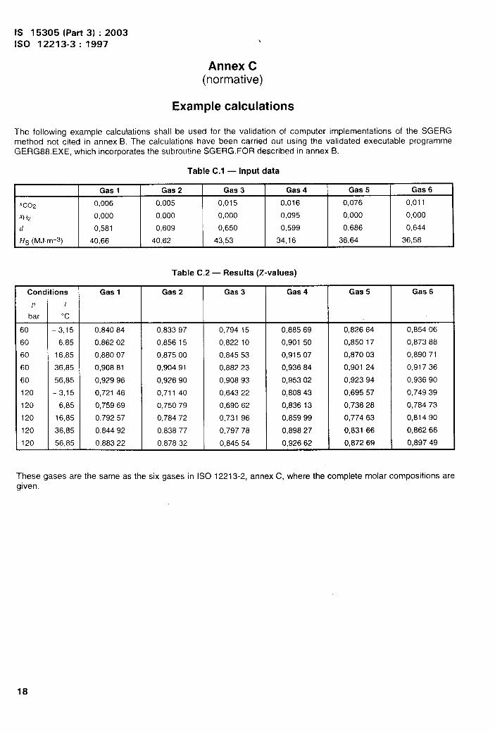
Annex C(normative)
Example calculations
The following example calculations shall be used for the validation of computer implementations of the SGERGmethod not cited in annex B. The calculations have been carried out using the validated executable programmeGERG88.EXE, which incorporates the subroutine SGERG.FOR described in annex B.
Table C.1 — Input data
Gas 1 Gas 2 Gas 3 Gas 4 Gas 5 Gas 6
Xco’i 0,006 0,005 0,015 0,016 0,076 0,011
W2 0,000 0,000 0,000 0,095 0,000 0,000
d 0,581 0,609 0,650 0,599 0,686 0,644
Hs (MJm-3) 40,66 40,62 43,53 34,16 36,64 36,58
Table C.2 — Results (Z-values)
Cond
-J
p
bar
60
60
60
60
60
120
120
120
120
120
ions
/
“c
-3,15
6,85
16,85
36,85
56,85
-3,15
6,85
16,85
36,85
56,85
Gas 1
0,84084
0,86202
0,88007
0,90881
0,92996
0,72146
0,75969
0,79257
0,84492
0,88322
Gas 2
0,83397
0,85615
0,87500
0,90491
0,92690
0,71140
0,75079
0,78472
0,83877
0,87832
Gas 3
0,79415
0,82210
0,84553
0,88223
0,90893
0,64322
0,69062
0,73196
0,79778
0,84554
Gas 4
0,88569
0,90150
0,91507
0,93684
0,95302
0,80843
0,83613
0,85999
0,89827
0,92662
Gas 5
0,82664
0,85017
0,87003
0,90124
0,92394
0,69557
0,73828
0,77463
0,83166
0.87269
Gas 6
0,85406
0,87388
0,89071
0,91736
0,93690
0,74939
0,78473
0,81490
0,86266
0.89749
rhese gases are the same as the six gases in ISO 12213-2, annex C, where the complete molar compositions aregiven.
18
IS 15305 (Part 31:2003ISO 12213-3:1997
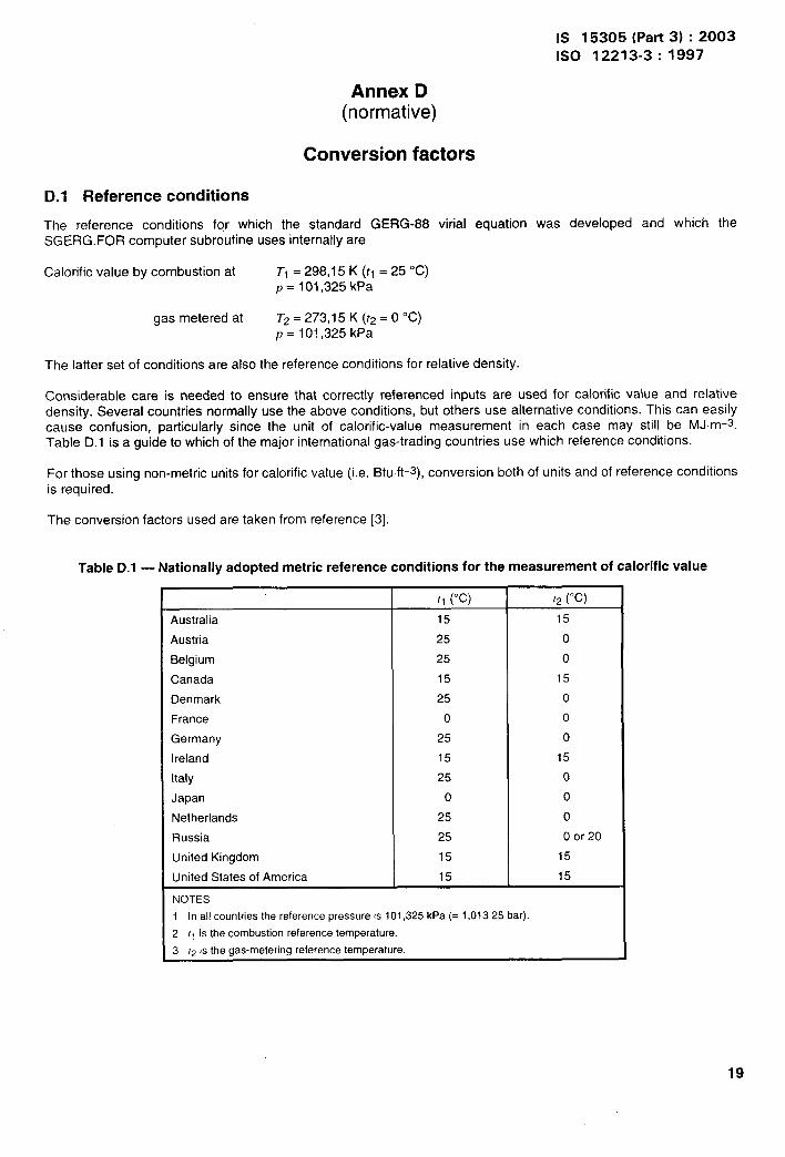
Annex D(normative)
Conversion factors
D.1 Reference conditions
The reference conditions for which the standard GERG-88 virial equation was developed and which theSGERG.FOR computer subroutine uses internally are
Calorific value by combustion at TI = 298,15 K ([1 =25 ‘C)p = 101,325 kPa
gas metered at T2=273,15K(t2=00C)p = 101,325 kPa
The latter set of conditions are also the reference conditions for relative density.
Considerable care is needed to ensure that correctly referenced inputs are used for calorific value and relativedensity. Several countries normally use the above conditions, but others use alternative conditions. This can easilycause confusion, particularly since the unit of calorific-value measurement in each case may still be MJm-s.Table D.1 is a guide to which of the major international gas-trading countries use which reference conditions.
For those using non-metric units for calorific value (i.e. Btuft-3), conversion both of units and of reference conditionsis required.
The conversion factors used are taken from reference [3].
Table D.1 — Nationally adopted metric reference conditions for the measurement of calorific value
[1 (“c) 12(“c)
Australia 15 15
Austria 25 0
Belgium 25 0
Canada 15 15
Denmark 25 0
France o 0
Germany 25 0
Ireland 15 15
Italy 25 0
Japan o 0
Netherlands 25 0
Russia 25 0 or 20
United Kingdom 15 15
United States of America 15 15
NOTES
1 In all countriesthe referencepressureis 101,325kPa (= 1,01325 bar).
2 /1 is the combustionreferencetemperature.
3 12is the gas-meteringreferencetemperature.—
19
IS 15305 (Part 3) :2003
1S0 12213-3: 1997
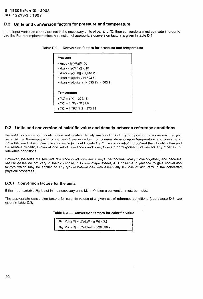
D.2 Units and conversion factors for pressure and temperature
If the input variables ~ and t are not in the necessary units of bar and “C, then conversions must be made in order touse the Fortran implementation. A selection of appropriate conversion factors is given in table D.2.
Table D.2 — Conversion factors for pressure and temperature
Pressure
p (bar) = k(kPa)]H 00
p (bar) = ~(MPa)] x 10
p (bar) = ~(atm)] x 1,01325
p (bar) = ~(psia)]ll 4,5038
P (bar) = k(psig) + 14,695 9]/14,5038
Temperature
I (°C) = T(K) – 273,15
r (“C) = [t(°F) – 32]11,8
[ (“C) = [t(”R)] /1,8 – 273,15
D.3 Units and conversion of calorific value and density between reference conditions
Because both superior calorific value and relative density are functions of the composition of a gas mixture, andbecause the thermophysical properties of the individual components depend upon temperature and pressure inindividual ways, it is in principle impossible (without knowledge of the composition) to convert the calorific value andthe relative density, known at one set of reference conditions, to exact corresponding values for any other set ofreference conditions.
However, because the relevant reference conditions are always thermodynamically close together, and becausenatural gases do not vary in their composition to any major extent, it is possible in practice to give conversionfactors which may be applied to any typical natural gas with essentially no loss of accuracy in the convertedphysical properties.
D.3.”1 Conversion factors for the units
If the input variable t{s is not in the necessary units MJ.m-3, then a conversion must be made.
The appropriate conversion factors for calorific values at a given set of reference conditions (see clause D.1 ) aregiven in table D.3.
Table D.3 — Conversion factors for calorific value
I Hs (MJm-3) = [Hs(kWhm-3)] x 3,6
Hs (MJm-s) = [Hs(Btuft-s)]/26,8392 I
20
IS 15305 (Part 3) :20031s0 12213-3:1997
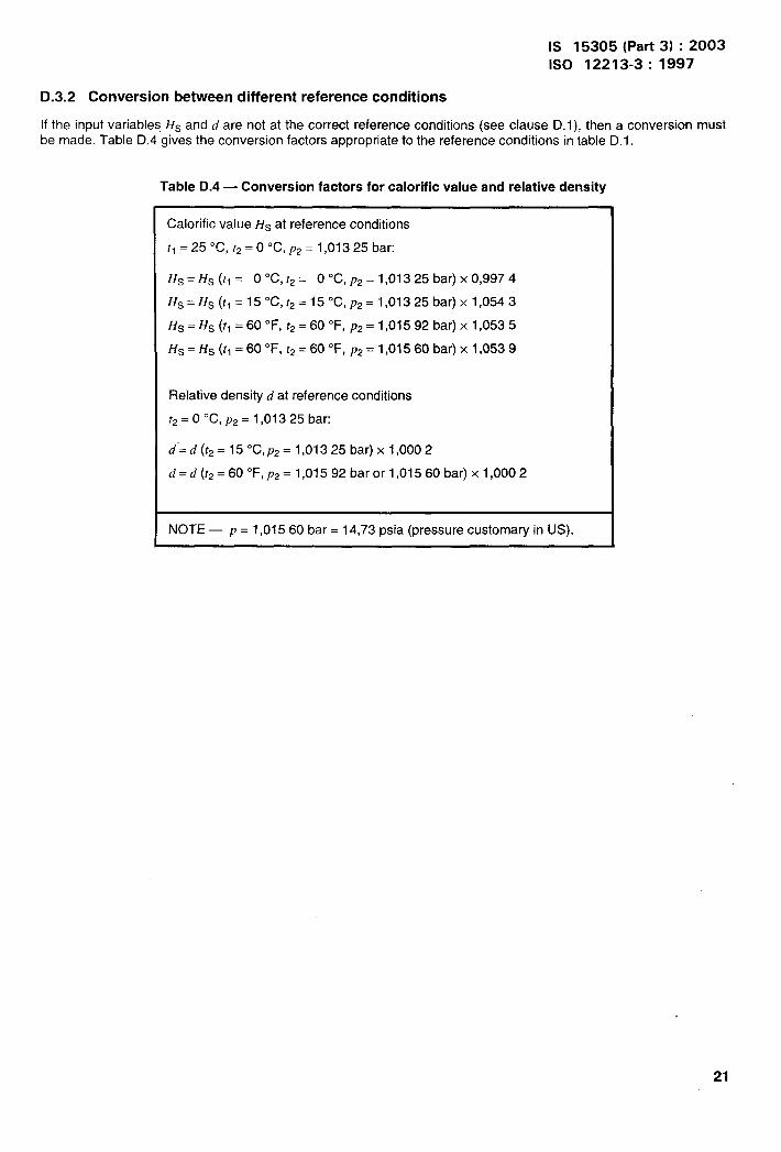
D.3.2 Conversion between different reference conditions
If the input variables HS and d are not at the correct reference conditions (see clause D. 1), then a conversion mustbe made. Table D.4 gives the conversion factors appropriate to the reference conditions in table D.1.
Table D.4 — Conversion factors for calorific value and relative density
Calorific value Hs at reference conditions
r, = 25 ‘C, fz = O “C, p2 = 1,01325 bar:
HS = H.s (t, = O ‘C, t2 = O “C, pz = 1,01325 bar) x 0,9974
Hs=Hs(tl= 150 C,t2=150C, p2=l,01325 bar) xl,0543
HS = HS (t, =60 “F, rp = 60 ‘F, pz = 1,01592 bar) x 1,0535
Hs= HS (t, =60 “F, t2= 60 “F, p2 = 1,01560 bar) x 1,0539
Relative density d at reference conditions
?2= O “C, p2 = 1,01325 bar:
d’=d(t2=150C, p2= l,01325bar)x 1,0002
d=d(r2= 600 F,p2=l,01592 barorl ,015 60 bar) xl,0002
NOTE — p = 1,01560 bar= 14,73 psia (pressure customary in US).
21
IS 15305 (Part 3) :2003ISO 12213-3:1997
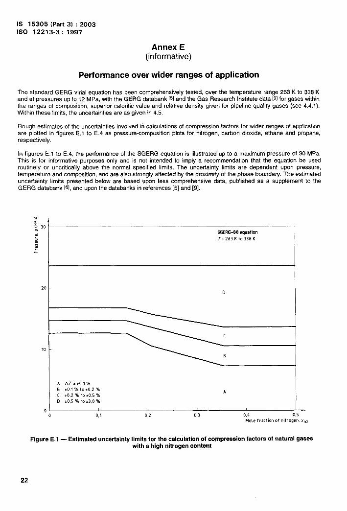
Performance
Annex E(informative)
over wider ranges of application
The standard GERG virial equation has been comprehensively tested, over the temperature range 263 K to 338 Kand at pressures up to 12 MPa, with the GERG databank [5] and the Gas Research Institute data P] for gases withinthe ranges of composition, superior calorific value and relative density given for pipeline quality gases (see 4.4.1).Within these limits, the uncertainties are as given in 4.5.
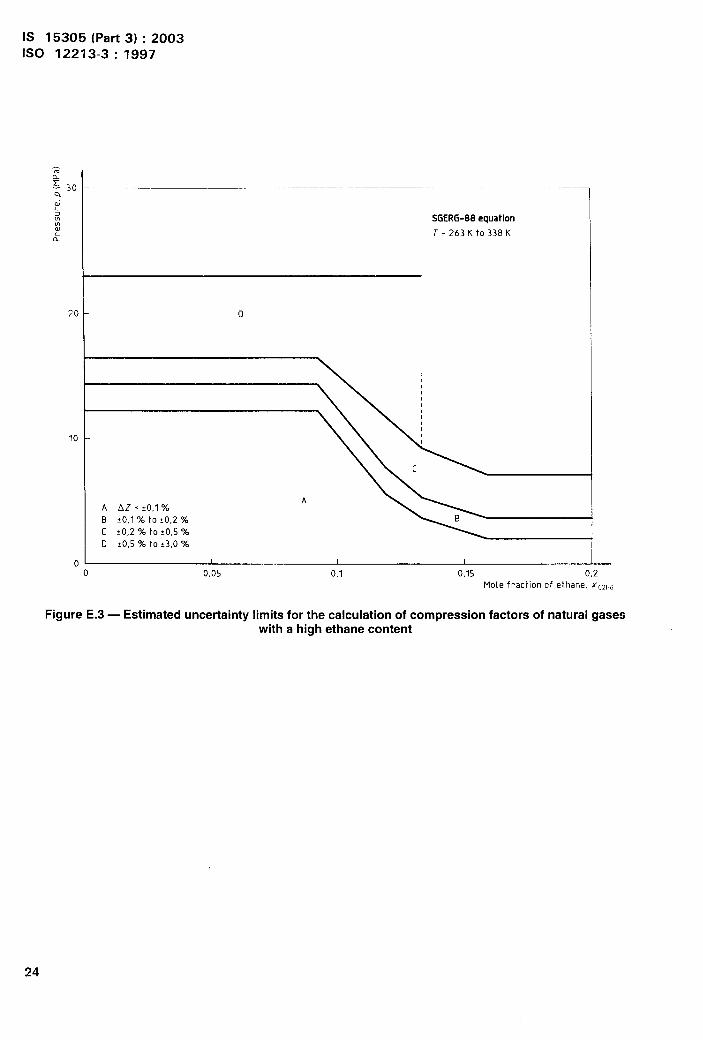
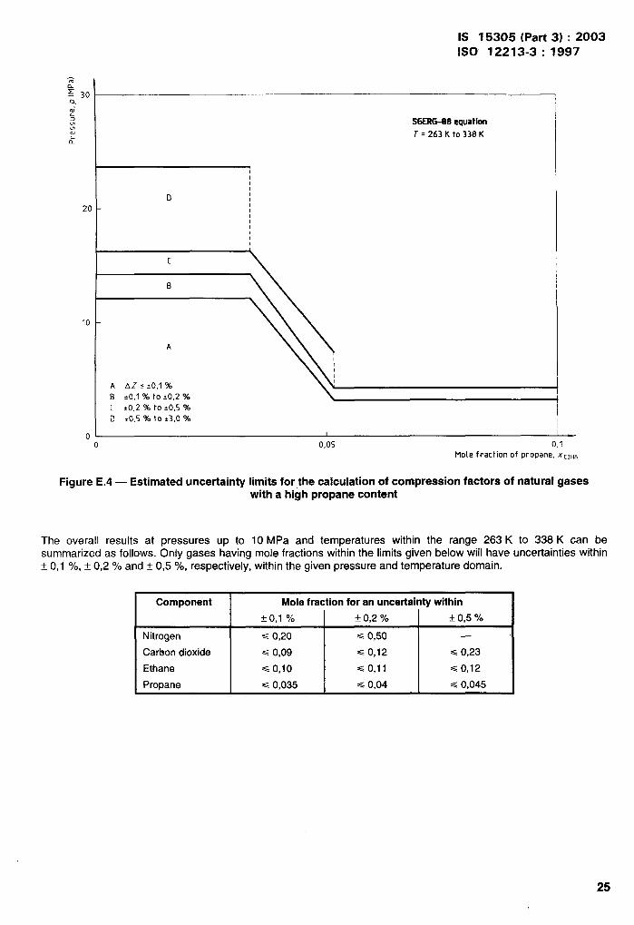
Rough estimates of the uncertainties involved in calculations of compression factors for wider ranges of applicationare plotted in figures E.1 to E.4 as pressure-composition plots for nitrogen, carbon dioxide, ethane and propane,respectively.
In figures E. 1 to E.4, the performance of the SGERG equation is illustrated up to a maximum pressure of 30 MPa.This is for informative purposes only and is not intended to imply a recommendation that the equation be usedroutinely or uncritically above the normal specified limits. The uncertainty limits are dependent upon pressure,temperature and composition, and are also strongly affected by the proximity of the phase boundary. The estimateduncertainty limits Dresented below are based uDon less comr3rehensive data, rwblished as a supplement to theGERG da~abank [~1,and upon the databanks in references [5] and [9]. “
SGERG-88equationT=263Kto338K
D
A AZ s 10,1 %
B tO,l % to i0,2 % A[ ?0,2 % to ?0,5 %
D *0,5 % to *3,0 %
1 I t 1 -—
0 0,1
Figure E.1 — Estimated uncertainty
0,2 0,3 0,6 0,5
Mole fraction of nitrogen, x~z
limits for the calculation of compression factors of natural gaseswith a high nitrogen content
22
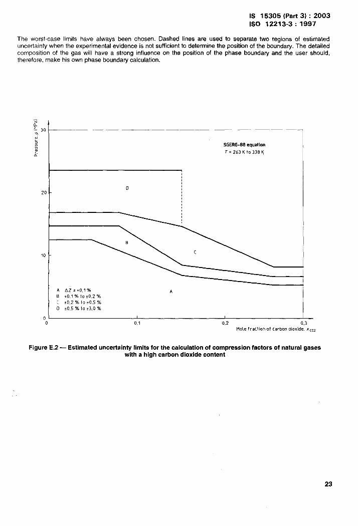
IS 15305 (Part 3) :20031s0 12213-3:1997
The worst-case limits have always been chosen. Dashed lines are used to separate two regions of estimateduncertainty when the experimental evidence is not sufficient to determine the position of the boundary. The detailedcomposition of the gas will have a strong influence on the position of the phase boundary and the user should,therefore, make his own phase boundary calculation.
-%L: 3C
w’5.mw
k
2(
10
II
SGERG-88equationT=263Ktc)338K
D
!1
A AZ z <0,1 % AB *0,1 % to ~0,2 %c *0,2 % to +0,5 %
D !0,5 % to f3,0 %
—o 0,1 0,2 0,3
Mole fraction of carbon dioxide, XC02
Figure E.2 — Estimated uncertainty limits for the calculation of compression factors of natural gaseswith a high carbon dioxide content
23
IS 15305 (Part 3) :2003ISO 12213-3: 1997
A
SGERG-88equation
T=263Kto338K
o
A AZ s !0,1 “hB *0,1 % to i0,2 %
c 10,2 % to *0,5 “A
D 10,5 % to:3,0 “xl
—o 0,05 0,1 0,15 0,2
Mote fraction of ethane, XCZH6
Figure E.3 — Estimated uncertainty limits for the calculation of compression factors of natural gaseswith a high ethane content
IS 15305 (Part 3) :2003
1s0 12213-3:1997
-an
~ 30Qw“5mm
SGERG-88equational T=263Kto338K&
1!1!
D 11
20 -11111II,
c
B
10
A
A AZ s 10,1 %B ?0,1 % to io,z %
[ >0,2 % to to,s %
o 20,5 “A to 23,0 %
n 1 1
0 0,05 0,1Mole fraction of propane, X’[3H5
Figure E.4 — Estimated uncertainty limits for the calculation of compression factors of natural gaseswith a high propane content
The overall results at pressures up to 10 MPa and temperatures within the range 263 K to 338 K can besummarized as follows. Only gases having mole fractions within the limits given below will have uncertainties within~ (),1 %, + 0,2 % and f (),!5 %, respectively, within the given pressure and temperature domain.
Component Mole fraction for an uncertainty within
* 0,1 0/0 ~ (),2 y! f 0,5 %
Nitrogen s 0,20 c 0,50 —
Carbon dioxide c 0,09 ==0,12 s 0,23
Ethane < 0,10 ==0,11 ==0,12
Propane G 0,035 s 0,04 ==0,045
25
IS 15305 (Part 3) :2003ISO 12213-3: 1997
Annex F(informative)
Subroutine SGERG.FOR in Fortran
c
C**+************** ******************* ******************* ******************
ccccccccccccccccccccccccccccccccccccccccccccccccccc
last update: 07.08.96 M. Jaeschke, J. Sikora
***********+** ***** GERG-88 VIRIAL EQUATION *************** ********
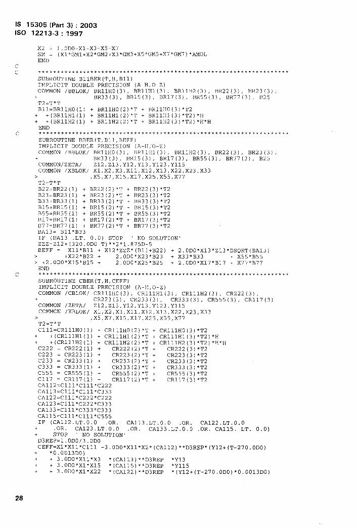
SUBROUTINE SGERG
SGERG ‘ CALCULATES THE COMPRESSION FACTORS OF NATURAL GASES USINGA SIMPLIFIED GAS ANALYSIS
LEGAL COPIES OF THIS PROGFUU4 MAY ONLY BE OBTAINED FROM THEMEMBERS OF THE GERG WORKING GROUP ON COMPRESSIONFACTORS OF NATURAL GAS AS GIVEN IN THE GERG TECHNICALMONOGRAPH TM 5 (1991)
The calculations are based on the following fourinput parameters for the gas analysis:
(Valid ranges:)-1- X3: mole fraction C02 ( 0.0 -> 0.3 )-2- HS: calorific value in MJ/mA3 *) ( 20 -> 48 )-3- F04: relative density *) ( 0.55 -> 0.9 )-4- X5: mole fraction H2 ( 0.0 -> 0.1 )
*) note : metering atT= 0.0 c , P = 1.01325 bar: combustion at T = 25.0 C
Further input parameters used are:
P : pressure in bar (0 l-> 120 )TC: temperature in degrees Celsius (-23 -> 65 )
A CALCULATED value for X2, the molar fraction of nitrogenis returned.
The calculated values are:
z: compression factorD : molar density in mol/m**3
**** For some compilers the SAVE option has to be set explicitly ****
SYNTAX : CALL SGERG(X2, X3,HS,RM,X5,P, TC,Z,D)
The coefficients used in this program are conform with thevalues given in subroutine GAS682, from July 20,1988, appendedto report 8807, Van der Waals Laboratory, Amsterdam.
J.P.J. Michels & J.A. SchoutenAugust 16, 1991
Values for the gas constant, molar ma”sses, calorific valuesand the density of air conform with 1S0 6976 (1995) .
ccccc(:ccccccccccccccccccccccccccccccccccccccccccccccccccccccccccccccccccccccc
SIJBROUTINE SGERG(X2,X3, HS,RM,X5, P,TC, Z,D)IMPLICIT DOUBLE PRECISION (A-H,O-Z)IF( P.LT. 0.0 .OR. P .GT.120.0) STOP ‘ PRESSURE OUT OF RANGE’IF(Tc.LT.-23.O .OR. TC.GT .65.0) STOP ‘ TEMPERATURE OUT OF RANGE’CALL SGERG1(P, TC,X2,X3,X5 ,HS,RM,Z,D)RETURNEND
26
IS 15305 (Part 3) :2003ISO 12213-3:1997
c ************** *************** *************** *************** *********
SUBROUTINE SGERG1(P,TC,Q2,Q3,Q5,QM, RM,Z,D)IMPLICIT DOUBLE PRECISION (A-H,O-Z)COMMON /RBLOK1 AMOL,HSCOMMON /XBLOK/ x1,x2,X3,X11,X12,X13, X22,X23,X33
> ,X5,X7,X15,X17,X25,X55, x77COMMON /MBLOK/ GMIRO,GMIR1, GM2,GM3,GM5 ,GM7, FA,FB,RL,T0,H5,H7 ,RHS = QMX3 = Q3X5 = Q5
c IF(RM.LT. 0.55.OR. RM.GT. 0.90) STOP ‘REL. MASS OUT OF RANGE’c IF(X3.LT. 0.0 .OR. X3.GT. 0.30) STOP ‘C02 OUT OF RANGE’c IF(HS.LT.20.O .OR. HS.GT.48.0 j STOP ‘CALOR. VALUE OUT OF RANGE’
IF ((0.55+0.97*X3-0.45*X5) .GT.RM)STOP ‘CONFLICTING INPUT’SM = RM*RLx7 = X5*0.0964D0x33 = x3*x3x55 = x5*x5X77 = x7*x7BEFF= -0.065D0H = 1000.ODO7+MoL. l.ODO/(FA+BEFF)K =0KK=O
1 CALL SMBER(H, SMT1)IF(ABS(SM-SMT1) .GT. 1.D-6) THEN
CALL SMBER(H+l.ODO, SMT2 )DH= (SM-SMTl)/(SMT2-SMTl)H = H+DHKK = KK+l
IF(KK.GT.20)STOP ‘ NO CONVERGENCY #1’GO TO 1
END IFXll = X1*X1X12 = XI.*X2X13 = X1*X3x22 = X2*X2X23 = x2*x3X25 = X2*X5X15 = X1*X5Xii’ = X1*X7CALL B1lBER(TO,H,B1l)CALL BBER(TO,B1l,BEFF)AMoL= l.ODO/(FA+BEFF)HSBER = X1*H*AMOL+ (X5*H5+X7*H7 )*AMOLIF(ABS(HS-HSBER) .GT.1.OD-4) THEN
K = K+lIF(K.GT.20)STOP ‘NO CONVERGENCY #2’GO TO 1
END IFIF(X2.LT.-O.O1 .OR. X2.GT.O.5) STOP ‘CALC. N2 OUTIF(X2+X3.GT.0.5) STOP ‘N2 + C02 OUT OF RANGE’IF (0.55+.4*x2+0.97*X3-0 .45*X5) .GT.RM)
+ STOP ‘CONFLICTING RESULT FOR N2’Q2 = X2T = TC+TOCALL B1lBER(T,H,B1l)CALI, BBER(T,B1l,B)CALL CBER(T,H,C)CALL ITER(P, T,B,C,V,Z,)D = l.ODO/VENDSUBROUTINE SMBER(H,SM)IMPLICIT DOUBLE PRECISION (A-H,O-Z)COMMON /RBLOK/ AMOL,HSCOMMON /XBLOK/ X1,X2,X3,X11,X12,X13, X22,X23,X33
OF RANGE’
> ,X5,X7,X15,X17,X25,X55 ,x71COMMON /MBLOK/ GMIRq, GMlRl,GM2,GM3,GM5 ,GM7, FA,FB,RL,T0,H5,H7 ,RGM1= GMIRO+GMIR1*Hxl = (HS-(x5*H5+X7*H7) *m0L) /H/AMOL
27
IS 15305 (Part 3) :2003ISO 12213-3:1997
X2 = 1.0 DO-X1 -X3-X5-X7SM = (x1*GM1+x2*GM2 +x3* GM3+X5*GM5 +X7* GM7)*AMOLEND
cc ************** *************** *************** ************* ***********
SUBROUTINE BIIBER(T,H,B1l)IMPLICIT DOUBLE PRECISION (A-H,O-Z)COMMON /BBLOK/ BR11HO(3), BR11H1!3), BR11H2 (3), BR22 (3), BR23 (3),
+ BR33 (3), BR15(3), BR17(3), BR55(3), BR77 (3), B25T2=T*TB1l=BR1lHO(l) + BR11HO(2)*T + BR11HO(3)*T2
+ +(BR1lH1(l) + BR11H1(2)*T + BR11H1(3)*T2)*H+ +(BR11H2 (1) + BR11H2(2)*T + BR11H2(3)*T2)*H*HEND
c ************** ************** ************** ************* ************ *
SUBROUTINE BBER(T,B1l,BEFF)IMPLICIT DOUBLE PRECISION (A-H;O-Z)COMMON /BBLOK/ BR11HO(3), BR11H1(3), BR11H2 (3), BR22(3), BR23 (3),
+ BR33 (3), BR15 (3), BR17(3), BR55(3), BR77(3), B25COMNON/ZETA/ Z12, Z13,Y12,Y13,Y123, Y115COMMON /XBLOK/ X1,X2,X3,X11,X12,X13,X22 ,X23,X33
> ,X5,X7,X15,X17,X25,X55 ,X77T2.T*TB22=BR22 (1) + BR22(2)*T + BR22(3)*T2B23=BR23 (1) + BR23(2)*T + BR23(3)*T2B33=BR33 (1) + BR33(2)*T + BR33(3)*T2B15=BR15(1) + BR15(2)*T + BR15(3)*T2B55=BR55 (1) + BR55(2)*T + BR55(3)*T2B17=BR17(1) + BR17(2)*T + BR17(3)*T2B77=BR77(1) + BR77(2)*T + BR77(3)*T2BA13= B11*B33IF (BA13 .LT. 0.0) STOP ‘ NO SOLUTION’ZZZ=Z12+ (320.0DO-T) **2*1 .875D-5BEFF = X1l’B1l + X12*ZZZ*(B11+B22) + 2. 0DO*X13*Z13*DSQRT(BA13 )
> +X22*B22 + 2.0DO*X23*B23 + X33*B33 + X55*B55> +2.0D0*X15*B15 + 2.0DO*X25*B25 + 2.0DCI*X17*B17 + X77*B77END
c ************* ************** ************** ************* ************* *
SUBROUTINE CBER(T,H,CEFF)IMPLICIT DOUBLE PRECISION (A-H,O-Z)COMMON /CBLOK/ CR111HO(3){ CR111H1(3), CR111H2 (3), CR222 (3),
+ CR223 (3), CR233 (3), CR333 (3), CR555(3), CR117(3)COMMON /ZETA/ Z12, Z13,Y12,Y13,Y123, Y115COMMON /XBLOK/ X1,X2,X3,X11,X12,X13, X22,X23,X33
> ,X5,X7,X15,X17,X25,X55 ,X77T2=T*TC1ll=CR1llHO(l) + CR111HO(2)*T + cR111HO(3)*T2
+ +(CR1llH1(l) + CR111H1(2)*T + cR111H1(3)*T2)*H+ +(CR111H2 (1) + CR111H2(2)*T + CR111H2(3)*T2)*H*HC222 = CR222 (1) + CR222(2)*T + CR222(3)*T2C223 = CR223 (1) + CR223(2)*T + CR223(3)*T2C233 = CR233 (1) + CR233(2)*T + CR233(3)*T2C333 = CR333 (1) + CR333(2)*T + CR333(3)*T2C555 = CR555(1) + CR555(2)*T + CR555(3)*T2C117 = CR117(1) + CR117(2)*T + CR117(3)*T2CA112=C111*C111*C222CA113=C111*C111*C333CA122=C111*C222*C222CA123=C111*C222*C333CA133=C111’C333*C333CA115=C111*C111*C555IF (CA112.LT.O.O .OR. CA113.LT.O.O .OR. CA122.LT.O.O
+ .OR. CA123.LT.O.O .OR. CA133.LT.O.O .OR. CA115. LT. 0.0)+ STOP ‘ NO SOLUTION’D3REP=l.ODO/3 .ODOCEFF=X1*X1l*C1ll +3 .C)DO*X11*X2 *(CA112)**D3REP* (Y12+(T-270.ODO)
+ *0.0013DO)+ + 3.0DO*X11*X3 * (CA113) **D3REP *Y13+ + 3.0DO*X1*X15 *(CA115)**D3REP *Y115+ + 3.0DO*X1*X22 *(CA122)**D3REP *(Y12+(T-270 .ODO)*O.0013DO)
28
IS 15305 (Part 3) :2003ISO 12213-3:1997
+ +6.0 DO* X1*X2*X3* (CA123) **D3REP *Y123+ +3 .0DO* X1*X33 * (CA133) **D3REP *Y13+ +x22*x2*c222 + 3.0DO*X22*X3*C223 + 3.0DO*X2*X33*C233+ +X3*X33*C333 + X5*X55*C555 + 3.0DO*X11*X7*C117RETURNEND
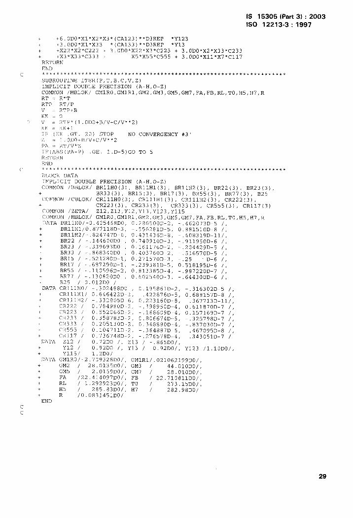
c ************** ************ ************** ************** ************* *
SUBROUTINE ITER(P,T,B,C,V,Z)IMPLICIT DOUBLE PRECISION (A-H,O-Z)COMMON /MBLOK/ GMIRO, GM1R1,GM2,GM3,GM5 ,GM7, FA,FB,RL,T0,H5,H7 ,RRT = R*TRTP= RT/Pv= RTP+BKK=O
5 v= RTP*(l.oDo+B/v+c/v**2 )KK . KK+lIF (KK .GT. 20) STOP ‘ NO CONVERGENCY #3rz = 1 .oDo+B/v+c/v**2PA -:.RT/V*ZrF(ABs(PA-p) .GE. l.D-5)G0 TO 5RETURNEND
r ************ ************ ************* ************ ************ *******
BLOCK DATAIMPLICIT DOUBLE PRECISION (A-H,O-Z)COMMON /BBLOK/ BR11HO(3), BR11H1(3), BR11H2(3), BR22(3), BR23(3),+ BR33 (3), BR15(3), BR17 (3), BR55(3), BR77(3), B25COMMON /CBLOK/ CR111HO(3), CR111H1(3), cR111H2 (3), CR222(3),
+ CR223 (3), CR233 (3) , CR333 (3), CR555(3), CR117(3)COMMON /ZETA/ Z12, Z13, Y12,Y13,Y123,Y115COMMON /MBLOK/ GMIRO, GM1R1,GM2,GM3 ,GM5, GM7,FA,FB,RL, T0,H5,H7,RDATA BRllHO/-O.425468DO, 0.286500D-2, -.462073D-5 /,
+ BRllH1/O.877118D-3, -.556281D-5, 0.881510D-8 /,+ BRllH2/-.8247476,6, 0.431436D-8, -.60831gD-11/,+ BR22 / -.144600D0 , O.74O91OD-3, -.91195fjD-6 /,+ BR23 / -.339693DO , 0.161176D-2, -.20442gD-5 /,+ BR33 / -.868340D0 , 0.403760D-2, -.516570D-5 /,+ BR15 / -.521280D-1, 0.271570D-3, -.25 “D-6 /,+ BR17 / -.687290D-1, -.239381D-5, 0.518195D-6 /,+ BR55 / -.110596D-2, 0.813385D-4, -.987220D-7 /,+ BR77 / -.130820D0 , 0.60254(ID-3, -.644300D-6 /,+ B25 / 0.012D0 /DATA CRlllHO/ -.302488D0 , 0.195861D-2, -.3163fJ2D-5 /,
+ CRlllH1/ 0.646422D-3, -.422876D-5, 0.688157D-8 /,+ CR1.llH2/ -.332805D-6, 0.223160D-8, -.367713D-11/,+ CR222 / 0.784980D-2, -,398950D--4, 0.611871)D-7 /,+ CR223 / 0.552066D-2, -.168609D-4, 0.157169D-7 /,+ CR233 / ().358783D-2, 0.806674D-5, -.325798D-7 /,+ CR333 / 0.205130D-2, 0.348880D-4, -.8371)31)D-7 /,+- CR555 ; O.1O4711D-2, -.364887D-5, .467095D-8 /,+ CR1l’7 / 0.736748D-2, -.276578D--4, .343051D-7 /DATA Z12 / 0.72D0 /, 213 / -.865D0/,
+ Y12 / 0.92D0 /, Y13 / 0.92D0/, Y123 /1.10DO/,+ Y1.15/ 1.2D0/DATA GMIRO/-2.7O9328DO/, GMIR1/.O2lO62l99DO/,
+ GM2 / 28.0135D0/, GM3 / 44.OIODO/,+ GN5 / 2.0159D0/, GM7 / 28.OIODO/,+ FA /22.414097D0/, FB / 22.710allDo/,+ RL / 1.292923DOI, TO / 273.15DOI,+ H5 / 285.83D0/, H7 / 282.98D0/+ R /0.0831451D0/END
cc
IS 15305 (Part 3) :20031s0 12213-3: 1997
[1]
[2]
[3]
[4]
[5]
[6]
[7]
[8]
[9]
Annex G(informative)
Bibliography
SCHOUTEN, J.A., MICHELS, J. P.J., JAESCHKE, M. “Calculation of the Compressibility Factor of Natural GasesBased on the Calorific Value and the Specific Gravity”, /nt. J. Thermophys., 11 (1),pp. 145-156(1990).
JAESCHKE, M., AUDIBERT, S., VAN CANEGHEM, P., HUMPHREYS, A. E., JANSSEN-VAN ROSMALEN, R., PELLEI, Q.,SCHOUTEN, J.A., MICHELS, J.P.J. “Simplified GERG Virial Equation for Field Use”, SPE Product Eng., 6 (3),pp. 350-355 (1991 ).
JAESCHKE, M., HUMPHREYS,A.E. “Standard GERG Virial Equation for Field Use: Simplification of the Input DataRequirements for the GERG Virial Equation — An alternative Means of Compressibility Factor Calculation forNatural Gases and Similar Mixtures”, GERG Technical Monograph TM5 (1991) and Fortschritt-Berichte VDI,Series 6, No. 266 (1992).
JAESCHKE, M., AUDIBERT, S., VAN CANEGHEM , P., HUMPHREYS, A. E., JANSSEN-VAN ROSMALEN, R., PELLEI, Q.,MICHELS, J. P.J., SCHOUTEN, J.A., TEN SELDAM, C.A. “High Accuracy Compressibility Factor Calculation forNatural Gases and Similar Mixtures by Use of a Truncated Virial Equation”, GERG Technical Monograph TM2(1988) and Fortschritt-Berichte VDI, Series 6, No. 231 (1989).
JAESCHKE, M., HUMPHREYS, A.E. “The GERG Databank of High Accuracy Compressibility FactorMeasurements”, GERG Technical Monograph TM4 (1990) and Fortschritt-Berichte VDI, Series 6, No. 251(1990).
JAESCHKE, M., HINZE, H.M., HUMPHREYS, A.E. “Supplement to the GERG Databank of High AccuracyCompressibility Factor Measurements”, GERG Technical Monograph TM7 (1996) and Fortschritt-Berichte VDI,Series 6, No. 355 (1996).
STARLING, K. E., SAVIDGE, J.L. “Compressibility Factors for Natural Gas and Other Related HydrocarbonGases”, American Gas Association (AGA) Transmission Measurement Commitee Report No. 8, AmericanPetroleum Institute (API) MPMS, chapter 14.2, Second Edition, November 1992.
Deutscher Verein des Gas- und Wasserfaches e.V, (DVGW). “The Gas Law Deviation Factors and Natural GasCompressibility Factors — Calculation and Application”, Gasmengenmessung, Technische Regeln, DVGWArbeitsblatt G486, August 1992.
SCHOUTEN, J.A., MICHELS, J.P.J. “Evaluation of PVT Reference Data on Natural Gas Mixtures — Final report”,Appendix to Gas Research Institute Report No. GR1/93-006, September 1992.
30
Bure., u of Indian Standards
131:;is a statutory institution established under the Bureau d Indian Standards Act, 1986 to promote
!)af II KXK.WS development of the activities of standardization, marking and quality certification of
GC.:1:-. and attending to connected matters in the country.
Copyright
BIS has the copyright of all its publications. No part of these publications may be reproduced in any “
form without the prior permission in writing of BIS. This does not preclude the free use, in the course
of implementing the standard, of necessary details, such as symbols and sizes, type or grade
des gnations. Enquiries relating to copyright be addressed to the Director (Publication), BIS.
Review of Indian Standards
Amendments are issued to standards as the need arises on the basis of comments. Standards are also
rwiewed periodically; a standard along with amendments is reaffirmed when such review indicates that
no changes are needed; if the review indicates that changes are needed, it is taken up for revision.
Users of Indian Standards should ascertain that they are in possession of the latest amendments or
wl~tm~~by referring to the latest issue of ‘BIS Catalogue’ and ‘Standards: Monthly Additions’.
TIIis Indian Standard has been developed from Dot: No. PCD 24 (2032).
Amendments Issued Since Publication
limend No. Date of Issue Text Affected
BUREAU OF INDIAN STANDARDS
i+eadquarters:
Ma.nak Bhavan, 9 Bahadur Shah Zafar Marg, New Delhi 110002 Telegrams: Manaksanstha;“elephones: 23230131, 23233375, 23239402 (Common to all offices)
F&gional Offices: Telephone
Manak Bhavan, 9 Bahadur Shah Zafar Marg{
23237617NEW DELHI 110002 23233841
1/14 C.I.T. Scheme Vll M, V.I.P,Road, Kankurgachi{
23378499,23378561KOLKATA 700054 23378626,23379120
SCO 335-336, Sector 34-A, CHANDIGARH 160022{
603843609285
C.I.T. Campus, IV Cross Road, CHENNAI 600113{
22541216,2254144222542519,22542315
Manakalaya, E9 MlDC, Marol, Andheri (East){
28329295,28327858MUMBAI 400093 28327891,28327892
AHMEDABAD. BANGALORE. BHOPAL, BH’UBANESHWAR. COIMBATORE. FARIDABAE2
GHAZIABAD. GUWAHATI. HYDERABAD. JAIPUR. KANPUR. LUCKNOW. NAGPUR.NALAGARH. PATNA. PUNE. RAJKOT. THIRUVANANTHAPURAM. VISAKHAPATNAM.
Printed at Simco Printing Press, Delhi