Embed Size (px)
Citation preview

WATER MONITORING STANDARDISATION TECHNICAL COMMITTEE
National Industry Guidelines for hydrometric monitoring PART 2: SITE ESTABLISHMENT AND OPERATIONS NI GL 100.02–2019 February 2019

National Industry Guidelines for hydrometric monitoring NI GL 100.02–2019
Page 2 of 45
Copyright
The National Industry Guidelines for hydrometric monitoring, Part 2 is copyright of the Commonwealth, except as noted below:
Quotations from Australian Standards: copyright is held by Standards Australia Limited, used with permission of Standards Australia and Standards New Zealand under Licence 1901-c052. Quotations from ISO Standards: copyright is held by Standards Australia Limited, used with permission of Standards Australia and Standards New Zealand under Licence 1901-c052. Quotations from Resources Information Standards Committee: copyright is held by Province of British Columbia, used with permission. Figures 1 and 2: copyright is held by P. Wessels, used with permission. Figure 3: copyright is held by the National Uniform Drillers Licensing Committee, used with permission.
Creative Commons licence
With the exception of logos, the material from third parties referred to above and material referred to under 'Other attributions' below, the National Industry Guidelines for hydrometric monitoring, Part 2 is licensed under a Creative Commons Attribution 3.0 Australia licence.
The terms and conditions of the licence are at: http://creativecommons.org/licenses/by/3.0/au/ To obtain the right to use any material that is not subject to the Creative Commons Attribution Australia licence, you must contact the relevant owner of the material. Attribution for this publication should be: © Commonwealth of Australia (Bureau of Meteorology) 2019 Other attributions The organisation below has applied a Creative Commons Attribution 4.0 International licence to their material reproduced in this publication. Please observe their unique attribution when reusing their material:
Attribution for material within this publication from the Federal Register of Legislation is clearly noted where the relevant material appears (refer to page 22)
National Industry Guidelines for hydrometric monitoring NI GL 100.02–2019
Page 3 of 45
Acknowledgements
This guideline was initially developed through a project funded under the Australian Government's Modernisation and Extension of Hydrologic Monitoring Systems program, administered by the Bureau of Meteorology. An industry consultation and review process included input from members of a Technical Reference Group convened by the Australian Hydrographers Association. In 2017 and 2018 the Water Monitoring Standardisation Technical Committee (WaMSTeC) led a periodic review of the National Industry Guidelines for hydrometric monitoring. WaMSTeC subcommittees conducted the review process and coordinated extensive industry consultation. 2018 review subcommittee members:
Jacquie Bellhouse (sponsor), Water Corporation, WA Kevin Dennis (sponsor), Department for Environment and Water, SA Fabienne d'Hautefeuille, Department of Industry–Lands and Water, NSW Mark Hopper, WaterNSW, NSW Max Best, WaterNSW, NSW David McPhee, Department of Environment, Land, Water and Planning, Vic Mick Hoban, Department of Environment, Land, Water and Planning, Vic Kemachandra Ranatunga, Bureau of Meteorology Linton Johnston, Bureau of Meteorology
Original primary drafting by:
Grant Robinson, then NSW Office of Water, NSW Paul Langshaw, then Rainmanwater Consulting
(Note that at the time of contribution, individuals may have been employed with different organisations and some organisations were known by other names).
National Industry Guidelines for hydrometric monitoring NI GL 100.02–2019
Page 4 of 45
Foreword
This guideline is part of a series of ten National Industry Guidelines for hydrometric monitoring. It has been developed in the context of the Bureau of Meteorology's role under the Water Act 2007 (Cwlth) to enhance understanding of Australia’s water resources. The Bureau of Meteorology first published these guidelines in 2013 as part of a collaborative effort amongst hydrometric monitoring practitioners to establish standardised practice. They cover activities relating to surface water level, discharge and water quality monitoring, groundwater level and water quality monitoring and rainfall monitoring. They contain high level guidance and targets and present non-mandatory Australian industry recommended practice. The initial versions of these guidelines were endorsed by the Water Information Standards Business Forum (the Forum), a nationally representative committee coordinating and fostering water information standardisation. In 2014, the functions and activities of the Forum transitioned to the Water Monitoring Standardisation Technical Committee (WaMSTeC). In 2017, as part of the ongoing governance of the guidelines, WaMSTeC initiated a 5-yearly review process to ensure the guidelines remain fit-for-purpose. These revised guidelines are the result of that review. They now include additional guidance for groundwater monitoring, and other updates which improve the guidelines' currency and relevance. WaMSTeC endorsed these revised guidelines in December 2018. Industry consultation has been a strong theme throughout development and review of the ten guidelines. The process has been sponsored by industry leaders and has featured active involvement and support from the Australian Hydrographers Association, which is considered the peak industry representative body in hydrometric monitoring. These guidelines should be used by all organisations involved in the collection, analysis and reporting of hydrometric information. The application of these guidelines to the development and maintenance of hydrometric programs should help organisations mitigate program under-performance and reduce their exposure to risk. Organisations that implement these guidelines will need to maintain work practices and procedures that align with guideline requirements. Within the guidelines, the term “shall” indicates a requirement that must be met, and the term “should” indicates a recommendation. The National Industry Guidelines can be considered living documents. They will continue to be subject to periodic WaMSTeC review at intervals of no greater than five years. In the review phase, WaMSTeC will consider any issues or requests for changes raised by the industry. Ongoing reviews will ensure the guidelines remain technically sound and up to date with technological advancements.
National Industry Guidelines for hydrometric monitoring NI GL 100.02–2019
Page 5 of 45
National Industry Guidelines for hydrometric monitoring
This document is one part of the National Industry Guidelines for hydrometric monitoring series, which can be found at http://www.bom.gov.au/water/standards/niGuidelinesHyd.shtml. The series contains the following parts:
Part 0: Glossary Part 1: Primary Measured Data Part 2: Site Establishment and Operations (this guideline) Part 3: Instrument and Measurement Systems Management Part 4: Gauging (stationary velocity-area method) Part 5: Data Editing, Estimation and Management Part 6: Stream Discharge Relationship Development and Maintenance Part 7: Training Part 8: Application of Acoustic Doppler Current Profilers to Measure Discharge in Open Channels Part 9: Application of in-situ Point Acoustic Doppler Velocity Meters for Determining Velocity in Open Channels Part 10: Application of Point Acoustic Doppler Velocity Meters for Determining Discharge in Open Channels
National Industry Guidelines for hydrometric monitoring NI GL 100.02–2019
Page 6 of 45
Table of Contents
1 Scope and general ........................................................................................................ 7 1.1 Purpose................................................................................................................ 7 1.2 Scope ................................................................................................................... 7 1.3 Application ........................................................................................................... 7 1.4 References ........................................................................................................... 7 1.5 Definitions ............................................................................................................ 9
2 Safety requirements ...................................................................................................... 9
3 Quality assurance ......................................................................................................... 9
4 Site establishment and operations ................................................................................. 9 4.1 General ................................................................................................................ 9 4.2 Surface water sites ............................................................................................. 11 4.3 Groundwater sites .............................................................................................. 21 4.4 Precipitation sites ............................................................................................... 31
Appendix A Training ....................................................................................................... 36
National Industry Guidelines for hydrometric monitoring NI GL 100.02–2019 Scope and general
Page 7 of 45
National Industry Guidelines for hydrometric monitoring
Part 2: Site Establishment and Operations
1 Scope and general
1.1 Purpose
The purpose of this document is to provide guidelines for recommended practice to ensure the quality of data gathered from hydrometric monitoring sites is sufficient for the intended use.
1.2 Scope
This document provides guidelines for the establishment and operation of hydrometric monitoring sites.
1.3 Application
This guideline applies to the following hydrometric monitoring site categories: 1. surface water level, discharge, water quality2. groundwater level, water quality3. precipitation.This guideline does not apply to discrete water quality sampling, nor the design of monitoring networks.
1.4 References
1.4.1 Normative references
The following standards contain provisions which, through reference in this text, constitute provisions of this guideline: 1. Bureau of Meteorology 1997, Guidelines for the siting and exposure of
meteorological instruments and observing facilities, Observation SpecificationNo. 2013.1, viewed 2 October 2018,<http://www.bom.gov.au/climate/cdo/about/observation_specification_2013.pdf>.
2. Bureau of Meteorology June 2002, Precipitation Gauge, Tipping Bucket Type,Equipment Specification A1980 (Issue 4).
National Industry Guidelines for hydrometric monitoring NI GL 100.02–2019 Scope and general
Page 8 of 45
3. International Organization for Standardization, Hydrometry - Measuring the water level in a well using automated pressure transducer methods, ISO/TR 23211:2009.
4. International Organization for Standardization, Hydrometric determinations -- Geophysical logging of boreholes for hydrogeological purposes - Considerations and guidelines for making measurements, ISO/TR 14685:2001.
5. International Organization for Standardization, Hydrometric determinations - Pumping tests for water wells - Considerations and guidelines for design, performance and use, ISO 14686:2003.
6. International Organization for Standardization, Manual methods for the measurement of a groundwater level in a well, ISO 21413:2005.
7. National Environment Protection (Assessment of Site Contamination) Measure 1999, F2013C00288, viewed 2 October 2018, <https://www.legislation.gov.au/Series/F2008B00713>.
8. National Uniform Drillers Licensing Committee, Minimum Construction Requirements for Water Bores in Australia, 3rd Edition, February 2012.
9. Resources Information Standards Committee 2006, Continuous water-quality sampling programs: operating procedure, ISBN 0-7726-5634-X, Province of British Columbia, Canada, viewed 2 October 2018, <https://www2.gov.bc.ca/assets/gov/environment/air-land-water/water/waterquality/water-quality-reference-documents/wq_ref_operating_proc.pdf>.
10. Standards Australia, Measurement of water flow in open channels Part 2.2: General—Establishment and operation of a gauging station, AS 3778.2.2—2001.
11. Standards Australia/Standards New Zealand, Water quality—Sampling, Part 11: Guidance on sampling of groundwaters, AS/NZS 5667.11:1998.
12. World Meteorological Organization 2008, Guide to Hydrological Practices, Volume I: Hydrology – From Measurement to Hydrological Information. WMO-No. 168. Sixth edition, 2008. ISBN 978-92-63-10168-6, viewed 2 October 2018, <http://www.whycos.org/hwrp/guide/index.php>.
13. World Meteorological Organization 2009, Guide to Hydrological Practices, Volume II: Management of Water Resources and Application of Hydrological Practices, WMO-No. 168, Sixth edition, 2009, viewed 2 October 2018, <http://www.whycos.org/hwrp/guide/index.php>.
1.4.2 Bibliography
Cognisance of the following was taken in the preparation of this guideline: 1. Inter-governmental Committee on Surveying and Mapping 02 April 2001, What is
the difference between WGS84 and GDA94?, ICSM 2000, viewed 2 October 2018, <http://www.homer.com.au/webdoc/gis/wgs84fact.pdf>.
2. Resources Information Standards Committee 2009, Manual of British Columbia Hydrometric Standards, Version 1.0, Province of British Columbia, Canada,
National Industry Guidelines for hydrometric monitoring NI GL 100.02–2019 Safety requirements
Page 9 of 45
viewed 2 October 2018, <https://www2.gov.bc.ca/assets/gov/environment/air-land-water/water/science-data/man_bc_hydrometric_stand_v10.pdf>.
3. Tauman M., Shaw P.J.R., Van Dijk M., 1980, Comparison of the Common Australian 203 Millimetre Rain Gauge with the WMO Reference Pit Gauge, Bureau of Meteorology Technical Report 37, Melbourne, Australia.
4. Wessels P., 2005, Flow-gauging structures in South African Rivers, Department of Water Affairs, South Africa.
5. World Meteorological Organization, International Workshop on Precipitation Measurement (3-7 December 1989, St. Moritz, Switzerland, WMO No. 328, 1989, viewed 2 October 2018, <http://onlinelibrary.wiley.com/doi/10.1002/hyp.3360050302/abstract>.
1.5 Definitions
For the purpose of this guideline, the definitions given in National Industry Guidelines for hydrometric monitoring, Part 0: Glossary, NI GL 100.00–2019 apply.
2 Safety requirements
All work undertaken for hydrometric projects shall be in conformance with the relevant government work health and safety legislation. Safe access agreements, where required, should be documented between the agency and landowners.
3 Quality assurance
Multiple sources of error exist in any monitoring system and these errors contribute to the overall measurement uncertainty. Continuous improvement efforts should be employed to reduce or eliminate as many sources of error as is realistic. If the overall measurement uncertainty exceeds customer requirements, further investigations shall be undertaken to identify and eliminate sources of error.
4 Site establishment and operations
4.1 General
4.1.1 Site identification and traceability
Each site shall have a unique site identifier and site name. Organisations shall document the following: a) protocols for numbering and naming of the site; b) geocoding to MGA94/GDA94 or MGA2020/GDA2020; c) recording site elevations in metres AHD; d) the type of sensors and measurements being obtained from the site; e) the nature of data transfer from the site;
National Industry Guidelines for hydrometric monitoring NI GL 100.02–2019 Site establishment and operations
Page 10 of 45
f) the location and identifiers for any reference levels used at the site; and g) the location of civil structures/conduits. Organisations should document geocodes for measuring points and elevation for each sensor. The protocols shall specify acceptable accuracies for geocodes and elevations. The estimated accuracies shall be recorded.
4.1.2 Datum
All level measurements shall be taken relative to a datum. The datum may be a local datum, and to enable accurate national comparison the local datum shall be referenced to the continental-wide levelling datum, namely the Australian Height Datum (AHD) or AHD Tasmania. Each organisation shall maintain records of all survey data and survey equipment test data.
4.1.3 Site inspections and maintenance
Inspection and maintenance shall be carried out at least once per year, or at intervals dictated by customer requirements. All points that are referenced to a datum should be surveyed regularly to maintain valid reference to the datum. Information captured shall be documented by the organisation.
4.1.4 Site data
The organisation shall permanently retain and archive primary measured data, in an unedited form in accordance with the minimum requirements from National Industry Guidelines for hydrometric monitoring Part 5: Data editing, estimation and management, NI GL 100.05–2019.
4.1.5 Instrument breakdown and malfunction
In the event of instrumentation breakdown or operation outside tolerance, the following apply: 1. Record the actual reading and reading outside tolerance, actions taken and
results of actions in the site and instrument histories. 2. All reasonable attempts shall be made to minimise data loss and inconsistencies.
All metadata pertaining to data from the non-conforming instrumentation shall be recorded and identified with the site identification and the dataset.
4.1.6 Data capture
Organisations shall define the appropriate triggers for data capture to meet customer requirements in a written procedure.
NOTE: Triggers would be based on, for example, data exceedance criteria, or fixed time logging, depending on instrumentation deployed. Where fixed time logging is employed, the frequency should be determined upon review of data and comparison with field observation and site history.
National Industry Guidelines for hydrometric monitoring NI GL 100.02–2019 Site establishment and operations
Page 11 of 45
4.1.7 Data verification frequency
Organisations shall consider customer requirements and intended use when determining requirements for verification measurements and records, including verification frequency. Data verification is not limited to calibration of a particular instrument, but verification that the collected data are supported by 'spot check' information through the likely range of measurement. Methods of data verification include physical site visit observations, observations by independent observers, duplicate transducers and facilities such as remote cameras.
4.2 Surface water sites
This section deals with the establishment and operation of a monitoring site on a lake, reservoir, stream, estuary or open channel (artificial or natural) for the measurement of level/stage, discharge and/or water quality. Examples of use of a surface water site include:
• calculation of discharge within an open channel (artificial or natural);
• calculation of discharge rates over a spillway;
• calculation of gross or effective storage;
• calculations with respect to the operation of hydraulic structures, infrastructure design safety and operation, hydroelectric power stations, etc.;
• monitoring of the variation in the water chemistry across the stream at a sampling site and at different flow volumes;
• monitoring of tidal level and flow;
• monitoring of compliance with water management rules; and
• flood forecasting and warning.
4.2.1 Site establishment
AS 3778.2.2—2001 Preliminary survey and selection criteria, Clause 5.3 applies. This clause includes:
The site selection for observation of stage should be governed by the purpose for which records are collected.1
This statement can be extended for all measurements of stage and/or discharge or water quality. Organisations shall maintain documentation of the purpose(s) of the site and the site selection process, and shall maintain a station history including records of key features
1 Source: AS 3778.2.2—2001 Clause 5.3. © Standards Australia Limited. Copied by the
Australian Government Bureau of Meteorology with the permission of Standards Australia and Standards New Zealand under Licence 1901-c052.
National Industry Guidelines for hydrometric monitoring NI GL 100.02–2019 Site establishment and operations
Page 12 of 45
and changes (e.g. photographs), details of nearby inflows or offtakes, and relevant environmental conditions. Documentation should be reviewed periodically and updated as changes occur.
4.2.1.1 Selection of sites
The selection of surface water sites is a complex process requiring a degree of judgment. When establishing a site, a range of factors should be considered in order to provide a cost-effective and reliable monitoring point suitable for its intended primary purpose. When selecting a surface water site, consideration should be given to the following factors:
• safety
• location o access – e.g., landowner and weather restrictions o physical infrastructure position (such as shelters, huts, travellerways,
instrument cabinets) – e.g., bank stability, solar exposure o protection – e.g., vandalism, fire/flood risk
• measurements required
• measurement range
• hydraulic characteristics o type of control o control stability and sensitivity o backwater effects and tidal influences o stream width and reach o stream roughness o vegetation
• communications availability.
4.2.1.1.A Level/stage monitoring sites
Level and stage monitoring may be undertaken at a range of sites including natural streams, artificial controls, estuaries, lakes, reservoirs, dams and similar. A key consideration when selecting a site for monitoring level/stage is its location in relation to the measurement structure. Dependant on the type of site and measurement structures, other aspects may influence site selection. Additional factors that should be considered when selecting an appropriate include those described below: 1. Natural controls
For natural controls it is difficult to determine the actual measurement location because of the irregular shape and the fact that the control may not be
National Industry Guidelines for hydrometric monitoring NI GL 100.02–2019 Site establishment and operations
Page 13 of 45
perpendicular to the flow, especially for low flows. The following aspects need to be taken into account in deciding the position: a) Drawdown effect (apply same methodology as artificial weirs). b) Instrumentation shall not be placed too far upstream of the control
otherwise the effect of the upstream pool will be lost. The upstream pool creates a change in flow conditions (reducing water velocity and turbulence effects).
c) If placed too far upstream, additional inflow or groundwater discharge can occur.
2. Artificial weirs
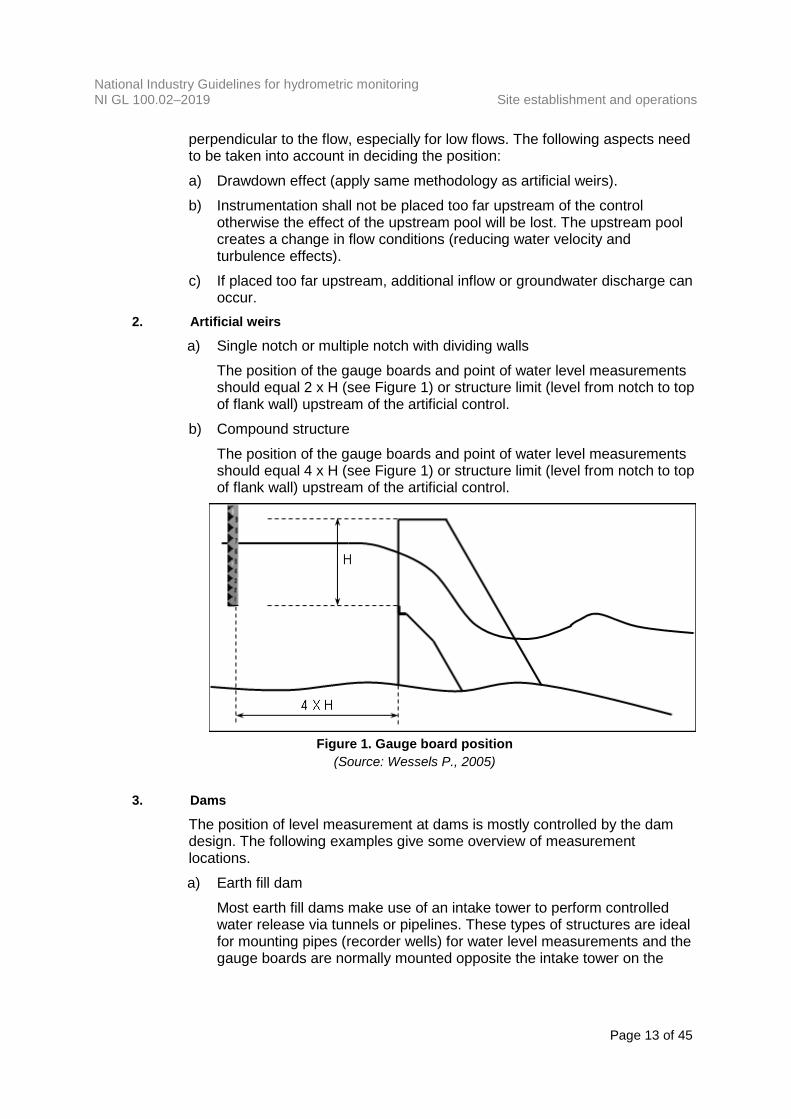
a) Single notch or multiple notch with dividing walls The position of the gauge boards and point of water level measurements should equal 2 x H (see Figure 1) or structure limit (level from notch to top of flank wall) upstream of the artificial control.
b) Compound structure The position of the gauge boards and point of water level measurements should equal 4 x H (see Figure 1) or structure limit (level from notch to top of flank wall) upstream of the artificial control.
Figure 1. Gauge board position
(Source: Wessels P., 2005)
3. Dams The position of level measurement at dams is mostly controlled by the dam design. The following examples give some overview of measurement locations. a) Earth fill dam
Most earth fill dams make use of an intake tower to perform controlled water release via tunnels or pipelines. These types of structures are ideal for mounting pipes (recorder wells) for water level measurements and the gauge boards are normally mounted opposite the intake tower on the

National Industry Guidelines for hydrometric monitoring NI GL 100.02–2019 Site establishment and operations
Page 14 of 45
upstream side of the earth fill dam. The position of the intake tower is normally far enough away from the spillway to prevent damage due to debris during flood events.
b) Concrete arch gravity dam Double arch concrete dams make it impractical to mount pipes on the upstream side of the dam wall due to the curvature and the depth, which in some cases can vary from 20 to 200 m. Provision is normally made for water level measurements by incorporating a recorder well or pipe connection inside the dam wall. Gauge boards are placed on the river bank far enough upstream to ensure that they are not affected by drawdown effects (see Figure 2). It is important to note that water level measurements or gauge board readings taken at the dam wall could be affected by drawdown as a result of the spillway design.
Figure 2. Illustration of drawdown effect (Source: Wessels P., 2005)
c) Concrete solid gravity dam Provision is made for water level measurements by either incorporating a recorder well or pipe connection inside the dam wall or installing pipes (recorder wells) on the upstream side vertical concrete face. Gauge boards are placed on a river bank far enough upstream to ensure that they are not affected by drawdown effects. It is important to note that water level measurements or gauge board readings taken at the dam wall could be affected by drawdown effects as a result of the spillway design.
Where a monitoring site measures reservoir spillway discharge, the monitoring site should be located sufficiently close to the spillway to accurately represent storage water level at the time of measurement, but a sufficient distance away to avoid hydraulic drawdown effects.
4. Wave action influences Wave action results in increased measurement uncertainty/tolerance of spot readings. It may be necessary to observe the levels for a longer period to get an estimated mean for the current level reading. Depending on the location and accessibility of a gauge, the certainty of the gauge reading may be improved by use of dampening tubes/boxes to dampen wave action.
National Industry Guidelines for hydrometric monitoring NI GL 100.02–2019 Site establishment and operations
Page 15 of 45
When establishing a site where wave action may occur, consideration should be given to employing dampening algorithms in the monitoring system/logic, or physical structures (stilling wells) to reduce the effects of wave action on sensor outputs as the sensor output may reflect the wave action, complicating further accurate assessment of the current sensor operational tolerance with regards to the validation reading. Metadata associated with validation visits should indicate the prevailing conditions and quantify the wave action range.
5. Setup and seiche influences
Setup and seiche can occur in dams, large stream monitoring pools as well as tidal installations. Setup, also referred to as wind slope, wind tide or wind denivelation, in a water body can result in an increase in measured level above the true ‘still’ level of the water body if the monitoring point is located at the downwind end of the water body. Conversely if the monitoring site is at the up-wind end of the water body due to a different wind direction, the measured level may be less than the true ‘still’ level. A setup often precedes a seiche, a periodic, small amplitude oscillation of the water surface about a nodal line. This condition is different from wave action in that the cycles are longer in time depending on the size of the reservoir, the preceding wind conditions (intensity, direction relative to the reservoir alignment and similar.) These conditions impact upon correct reporting of the correct ‘still water level’ of the water body. When establishing a site where setup and seiche are a factor, consideration should be given to incorporating algorithms or corrections to the data collection/reporting systems that take into account the temporal characteristics of these effects that may occur in the water body.
4.2.1.1.B Discharge monitoring sites
As discharge monitoring necessitates the monitoring of level, the requirements detailed in section 4.2.1.1.A apply. In addition, discharge monitoring sites should meet the following criteria where practical: 1. It is possible to get an accurate stage (water level) reading from the gauge over
the designed range. 2. The control, whether natural or artificial, is stable.
a) A stable natural control may be a: i. bedrock outcrop, or other stable riffle (shoal) for measuring during low
flow; ii. channel constriction for measuring at high flow; or iii. falls or cascade that is not submerged at any stage (water level).
b) A stable artificial control may be a: i. rated structure (flume, weir, and similar); ii. fish barrier (drop structure); iii. streambed sill (log, concrete, and similar);
National Industry Guidelines for hydrometric monitoring NI GL 100.02–2019 Site establishment and operations
Page 16 of 45
iv. constructed rock riffle; or v. culvert, bridge or ford.
3. The control (natural or artificial) is sufficient as to provide the required sensitivity in the relationship between stage and flow. Narrow or V-shaped controls provide greater sensitivity in that small changes in stage result in small changes in discharge. Broad, flat controls provide less sensitivity in that small changes in stage result in significant changes in discharge.
4. An effective channel control exists at medium to high flow ranges. 5. Discharge can be measured accurately at all stages where required, either
through a rated measurement structure or by means of a velocity meter (propeller or acoustic Doppler velocity meter, including in-situ meters).
6. Uniform flow conditions exist. 7. Flow should be confined to a single well-defined straight length of channel with
stable banks and uniform cross-section and slope: a) five times section width for artificial canals; and b) up to ten times section width for natural streams.
8. The velocity distribution over the width of the section at required capacity shall be evaluated (reduce the risk of an abnormal velocity distribution).
9. Slow approach velocities exist: a) Froude number of less than 0.35 for artificial structures; and b) Froude number less than 0.5 for natural controls.
10. Possible impact of roughness of the riverbed on the discharge shall be investigated.
11. The site is accessible, even during flood events. The following should be avoided where possible: 1. Conditions downstream that may cause variable backwater effects, such as from
tidal influences, flow in downstream tributaries, dams, in-stream vegetation or any other controlling features.
2. Prominent obstructions in a pool that can affect the flow pattern. 3. Sites with wide flood plains or sites where, during floods, water might flow in side
channels. 4. Bends or steep slopes upstream of the site. 5. Turbulent conditions downstream of the site caused by water entering a channel
from gates, valves, sluices or pipes. Measuring sites should be located a distance of at least 15 times the pipe diameter downstream of a point where full pipe flow enters a channel, and at least 10 times the section width downstream in other cases.
National Industry Guidelines for hydrometric monitoring NI GL 100.02–2019 Site establishment and operations
Page 17 of 45
4.2.1.1.C Continuous water quality monitoring sites
A well-planned water quality monitoring site needs to consider the location requirements of the sensor for the water quality variable being measured. Water quality sensors should be associated with stage and discharge measurement wherever possible, subject to customer requirements. The variation in the water chemistry across the stream at the sampling site at different flow levels should be determined before the site is established. Where possible, a well-planned, well-constructed continuous water quality monitoring site reflects the following criteria: 1. There should be good mixing of the flow to ensure the measuring point is
representative of conditions in the stream. 2. There shall be no tributaries in the general vicinity of the sampling site that could
affect uniform flow and increase cross-sectional variability. 3. There shall be one stream channel along which all of the flow passes. 4. There shall be minimal signs of erosion and deposition in the stream at the
sampling site. 5. Stable banks are required to accommodate periods of high water. (Adapted from Resources Information Standards Committee, 2006)
4.2.1.2 Design and construction
4.2.1.2.A Level/stage/discharge monitoring sites
AS 3778.2.2—2001, Clause 5.4 (Establishment of stage-discharge relation gauging station) applies for measurement of level and discharge. This specifies:
The reference gauge and water level recorder should be located as closely as possible to the measuring reach.2
Development, reconstruction or maintenance activities on hydrometric monitoring sites should aim to minimise the impact on stream ecology. When designing a surface water monitoring site, consideration should be given to facilitating or improving fish passage, minimising site disturbance and changes to natural flow regimes.
4.2.1.2.B Continuous water quality monitoring sites
The following from the Continuous water-quality sampling programs: operating procedure applies:
Sensor deployment refers to the way that the sensor comes into contact with the ambient water. There are two main deployment methods:
2 Source: AS 3778.2.2—2001 Clause 5.4. © Standards Australia Limited. Copied by the
Australian Government Bureau of Meteorology with the permission of Standards Australia and Standards New Zealand under Licence 1901-c052.
National Industry Guidelines for hydrometric monitoring NI GL 100.02–2019 Site establishment and operations
Page 18 of 45
a) The sensor is either placed in the stream—an ‘instream system’; or
b) The stream water is brought out of the stream to the sensor—called a ‘flow through system’ or a side-stream system.
The deployed equipment may be positioned in several different ways. It may be fixed vertically, fixed at an angle to the bank, or contained in a retractable boom. In lakes and slow-moving water such as in reservoirs, the deployment tube may be anchored to a buoy or raft. (Source: Resources Information Standards Committee, 2006)
4.2.1.3 Levels and cross-sections
Where the prevailing water level permits, as a minimum, the following assets shall be check levelled, utilising existing benchmarks at the site:
• staff gauges.
• cease to flow.
• orifice. AS 3778.2.2—2001, Section 6 (Direct discharge-gauging stations) specifies different survey requirements for different streamflow measurement methodologies, such as stationary meter, moving boat, and similar. Use of one of these techniques is mandatory. For cross-sections, preparatory work of AS 3778.2.2—2001, Clause 5.4.2 applies. In addition: 1. During establishment, the position of each cross-section should be identified by
visible and clearly identifiable permanent markers on the banks of the rivers, or by capturing coordinates of cross section limits by GPS stored as site metadata.
NOTE: Physical marking of cross-sections may not be permitted in all circumstances, e.g. within National Parks. In these cases, GPS metadata of cross-section position should be recorded.
2. Measurement uncertainty in estimation of width should not exceed 0.5% of the true value.
3. Cross-sectional information shall be recorded at establishment and during the operation of the site. The minimum requirement for cross-sections shall be two cross-sections: i) station control; and ii) the gauges/sensor reference point.
4. Depending on the nature of the stream topography it may also be beneficial to obtain: i) cross-sections at fixed cableway/traveller-way sections (potential uses
include high flow gauging evaluations); ii) long section surveys; and iii) high flow control survey information.
National Industry Guidelines for hydrometric monitoring NI GL 100.02–2019 Site establishment and operations
Page 19 of 45
5. Cross-section surveys shall be undertaken at documented intervals or when evidence indicates a change in stream topography has occurred or is suspected.
6. Additional cross-sections shall be taken as required for the development of, or to validate, stage-discharge relationships. See National Industry Guidelines for hydrometric monitoring, Part 6: Stream discharge relationship development and maintenance, NI GL 100.06–2019 for information when additional cross-sections are required.
7. All cross-section data shall be reduced (converted to ‘reduced level’) and documented in a relevant database. Raw and reduced field data shall be appropriately archived.
4.2.2 Site operations
4.2.2.1 Primary gauge plates calibration
AS 3778.2.2—2001, Clause 5.2.2 (Gauge-zero elevation) applies. This Section includes:
The zero of the gauge shall be correlated with a national datum through a station benchmark. The gauge zero and the other gauge divisions should be checked annually with respect to this benchmark.3
The national datum shall be a recognised datum, e.g. the Australian Height Datum. A calibration check (survey) shall be performed on the primary gauge plates, sensors/outlets and gauge zero against the site datum at documented intervals. These documented intervals should be based on the Australian Standard (AS 3778.2.2—2001) and guided by the following factors:
• organisation and/or customer requirements
• evidence of damage or movement to gauge plates and/or sensor outlets
• a shift in the rating, observed through gauging data. The gauge plates should be calibrated, and adjusted where an error greater than ±6 mm, or other documented figure meeting customer requirements, is detected using a survey method with sufficient precision to detect this. Where practical, the primary gauge and sensor/sensing point should not be physically connected. If it is not practical to separate them, each shall be checked against the site control datum.
4.2.2.2 Sensor spot checks (level and water quality)
If the difference between sensor system and reference reading is less than the tolerance, the data are within acceptance criteria and no adjustment is required.
3 Source: AS 3778.2.2—2001 Clause 5.2.2. © Standards Australia Limited. Copied by the
Australian Government Bureau of Meteorology with the permission of Standards Australia and Standards New Zealand under Licence 1901-c052.
National Industry Guidelines for hydrometric monitoring NI GL 100.02–2019 Site establishment and operations
Page 20 of 45
The sensor system may require adjustment where the difference between sensor system and reference reading is greater than the tolerance. Field sensor system spot checks shall be undertaken at a minimum frequency of one spot check per annum. Some instruments (e.g. water quality sensors) shall require more frequent spot checks. Refer to manufacturer’s manuals and the organisation’s calibration and spot check records to determine an optimal frequency of test and service. These records shall be retained and associated with site and instrument history so that other records for the site and instruments used can be found. Calibration records of reference instruments used to perform spot checks shall be maintained. Spot check records shall be retained.
NOTE: Refer to definitions of ‘spot check’ and ‘calibration’ in National Industry Guidelines for hydrometric monitoring, Part 0: Glossary, NI GL 100.00-2019.
4.2.2.3 Routine check and service visits
Organisations shall determine the optimum frequency of routine check and service visits based on purpose for the site and shall schedule activities to minimise the drift from acceptable tolerances for references, parameters measured and controlling features. Spot checks shall be undertaken and documented to determine that the difference between sensor system and reference reading is within the acceptable tolerance. Where the difference is outside tolerance, action shall be taken to investigate the cause and rectify, which may include undertaking a full calibration. Spot check records shall be retained.
4.2.2.4 Discharge measurement
A discharge measurement or gauging shall be undertaken at ‘gauge-able’ sites as specified by the organisation to maintain the accuracy for the purpose. The gauging should be computed in the field and the deviation checked against the stage-discharge curve. If the gauging deviates by greater than ±10% or some other figure specified by customers, then additional field validation checks shall be taken to determine any physical site attribute changes (shall be documented), or any technology discrepancies (stage recording, offsets, gauging equipment, etc.) or human impacts during the processes. An additional check gauging may be required to validate the change. If the current gauging deviates from the current rating table more than the customer/business agreed percentage then that site's rating shall be reviewed. Any real time users (such as water supply authorities) of the stage (water level) data should be notified of the suspected change as soon as possible. Gauging details shall be transferred to an appropriate data base and the original soft and hard copies archived.
National Industry Guidelines for hydrometric monitoring NI GL 100.02–2019 Site establishment and operations
Page 21 of 45
4.3 Groundwater sites
Groundwater hydrology is an interpretive science; because we cannot observe the resource directly, we must interpolate and extrapolate our understanding from known points of data. These measurements are the principal source of information about the hydrologic stresses acting on aquifers and how these stresses affect groundwater recharge, storage, and discharge. Monitoring sites (bores) should therefore be located such that the spatial distribution of monitoring points is sufficient to capture trends in condition of the resource over the areal extent of interest. The term ‘Monitoring Bore’ has been adopted as the standard term because it is most commonly used in hydrogeological investigations throughout Australia. Other terms often substituted are ‘observation well’ and ‘piezometer’. Monitoring bores include bores to:
• observe water levels
• observe ambient water quality and contamination plumes.
4.3.1 Site establishment
4.3.1.1 Selection of sites
Siting and design of a groundwater monitoring bore usually involves considering a range of factors in order to provide a cost-effective and reliable monitoring point. Minimum Construction Requirements for Water Bores in Australia applies when siting a bore. The site selection and bore design for a groundwater monitoring bore shall be governed by the purpose for which the data are being collected. Consideration of the following principles may assist in siting bores to meet the required monitoring network objectives. 1. Bores for regional groundwater monitoring should be sited, designed and
constructed to be representative of groundwater level trends and quality across the wider aquifer.
2. To characterise horizontal groundwater flow directions, a minimum of three bores are required for triangularisation to determine flow gradients. The bores should all be completed within the same aquifer.
3. To characterise vertical groundwater gradients (and potential groundwater vertical flow), ‘nested’ sites should be used. Generally, two or more bores are located at closely spaced intervals (e.g., 5 metres) but constructed so the production intervals are at different depths. There should be no overlap of the production interval depths within the nested bores. The bores may be installed within the same aquifer or separate aquifers depending on the type of investigation.
4. When installing monitoring bores to investigate potential groundwater contamination, at a minimum, one bore should be installed up-gradient from the site of potential contamination, and at least two bores should be installed
National Industry Guidelines for hydrometric monitoring NI GL 100.02–2019 Site establishment and operations
Page 22 of 45
down-gradient. The up-gradient bore will provide baseline water quality data for groundwater flowing into the site, and the down-gradient bores will provide data on potentially contaminated groundwater leaving the site. Additional bores will be required to accurately characterise the extent of a groundwater contamination plume. The National Environment Protection (Assessment of Site Contamination) Measure 1999, Schedule B2 (Volume 3) Section 8.3.1 provides the following guidance for groundwater contamination monitoring bore networks:
The groundwater monitoring bore network should cover an appropriate study area to delineate the lateral extent of the contamination; define background groundwater quality, the groundwater flow system for the geological units of interest; and to assess the risk to relevant receptors.4
4.3.1.2 Site identification and traceability
In addition to requirements in Section 4.1.1 organisations shall maintain documentation of the purpose(s) of the site and shall maintain a station history including records of: 1. Key features of the installation such as drillers logs and construction logs (these
should include details such as bottom depths, production intervals, casing diameters, etc.). Where applicable, additional data such as downhole geophysics or bore completion reports should also be referred to or appended to the dataset.
2. Changes made to the site over time (e.g. bottom depth checks, site photographs).
3. Purpose(s) for monitoring, for example groundwater characterisation and baseline acquisition, environmental value to protect (groundwater dependant ecosystem, aquifer, river level, wetland), impact propagation and value at risk either in terms of loss/ increase of pressure or contamination displacement, groundwater usage and aquifer response.
4. Available data on anthropogenic influences likely to impact groundwater levels and water quality, for example proximity to groundwater extraction or injection, and timing of readings when nearby pumping stations were operated if available.
4.3.1.3 Site characteristics
The location of the monitoring site shall be suitable for its intended primary purpose. A well-planned, well-constructed groundwater monitoring site meets the following criteria: 1. Is in a location that is expected to be representative of the groundwater level or
quality of the aquifer being monitored and meets the purpose of monitoring. 2. Considers the proximity of extraction or injection, or localised surface discharge
that may affect readings.
4 Sourced from the Federal Register of Legislation
(https://www.legislation.gov.au/Details/F2013C00288/Html/Volume_3), at 2 October 2018. For the latest information on Australian Government law please go to https://www.legislation.gov.au.
National Industry Guidelines for hydrometric monitoring NI GL 100.02–2019 Site establishment and operations
Page 23 of 45
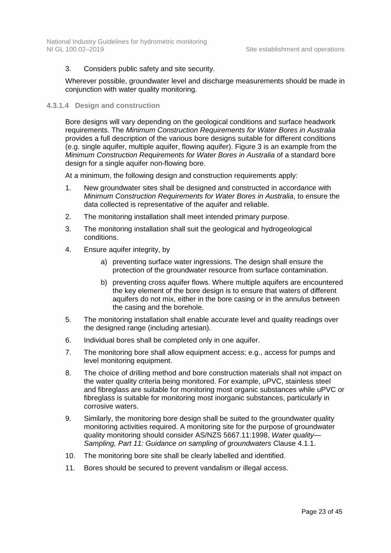
3. Considers public safety and site security. Wherever possible, groundwater level and discharge measurements should be made in conjunction with water quality monitoring.
4.3.1.4 Design and construction
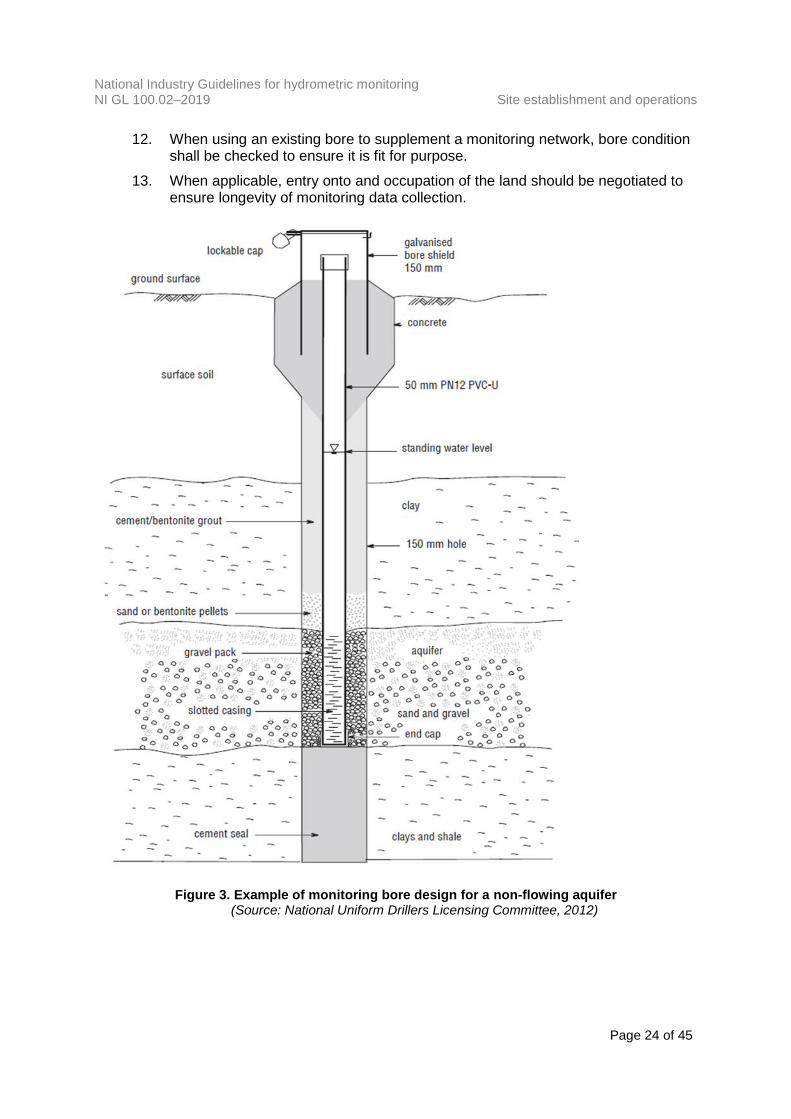
Bore designs will vary depending on the geological conditions and surface headwork requirements. The Minimum Construction Requirements for Water Bores in Australia provides a full description of the various bore designs suitable for different conditions (e.g. single aquifer, multiple aquifer, flowing aquifer). Figure 3 is an example from the Minimum Construction Requirements for Water Bores in Australia of a standard bore design for a single aquifer non-flowing bore. At a minimum, the following design and construction requirements apply: 1. New groundwater sites shall be designed and constructed in accordance with
Minimum Construction Requirements for Water Bores in Australia, to ensure the data collected is representative of the aquifer and reliable.
2. The monitoring installation shall meet intended primary purpose. 3. The monitoring installation shall suit the geological and hydrogeological
conditions. 4. Ensure aquifer integrity, by
a) preventing surface water ingressions. The design shall ensure the protection of the groundwater resource from surface contamination.
b) preventing cross aquifer flows. Where multiple aquifers are encountered the key element of the bore design is to ensure that waters of different aquifers do not mix, either in the bore casing or in the annulus between the casing and the borehole.
5. The monitoring installation shall enable accurate level and quality readings over the designed range (including artesian).
6. Individual bores shall be completed only in one aquifer. 7. The monitoring bore shall allow equipment access; e.g., access for pumps and
level monitoring equipment. 8. The choice of drilling method and bore construction materials shall not impact on
the water quality criteria being monitored. For example, uPVC, stainless steel and fibreglass are suitable for monitoring most organic substances while uPVC or fibreglass is suitable for monitoring most inorganic substances, particularly in corrosive waters.
9. Similarly, the monitoring bore design shall be suited to the groundwater quality monitoring activities required. A monitoring site for the purpose of groundwater quality monitoring should consider AS/NZS 5667.11:1998, Water quality—Sampling, Part 11: Guidance on sampling of groundwaters Clause 4.1.1.
10. The monitoring bore site shall be clearly labelled and identified. 11. Bores should be secured to prevent vandalism or illegal access.
National Industry Guidelines for hydrometric monitoring NI GL 100.02–2019 Site establishment and operations
Page 24 of 45
12. When using an existing bore to supplement a monitoring network, bore condition shall be checked to ensure it is fit for purpose.
13. When applicable, entry onto and occupation of the land should be negotiated to ensure longevity of monitoring data collection.
Figure 3. Example of monitoring bore design for a non-flowing aquifer
(Source: National Uniform Drillers Licensing Committee, 2012)
National Industry Guidelines for hydrometric monitoring NI GL 100.02–2019 Site establishment and operations
Page 25 of 45
4.3.2 Site operations
4.3.2.1 Reference points and datum points
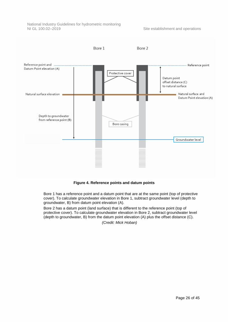
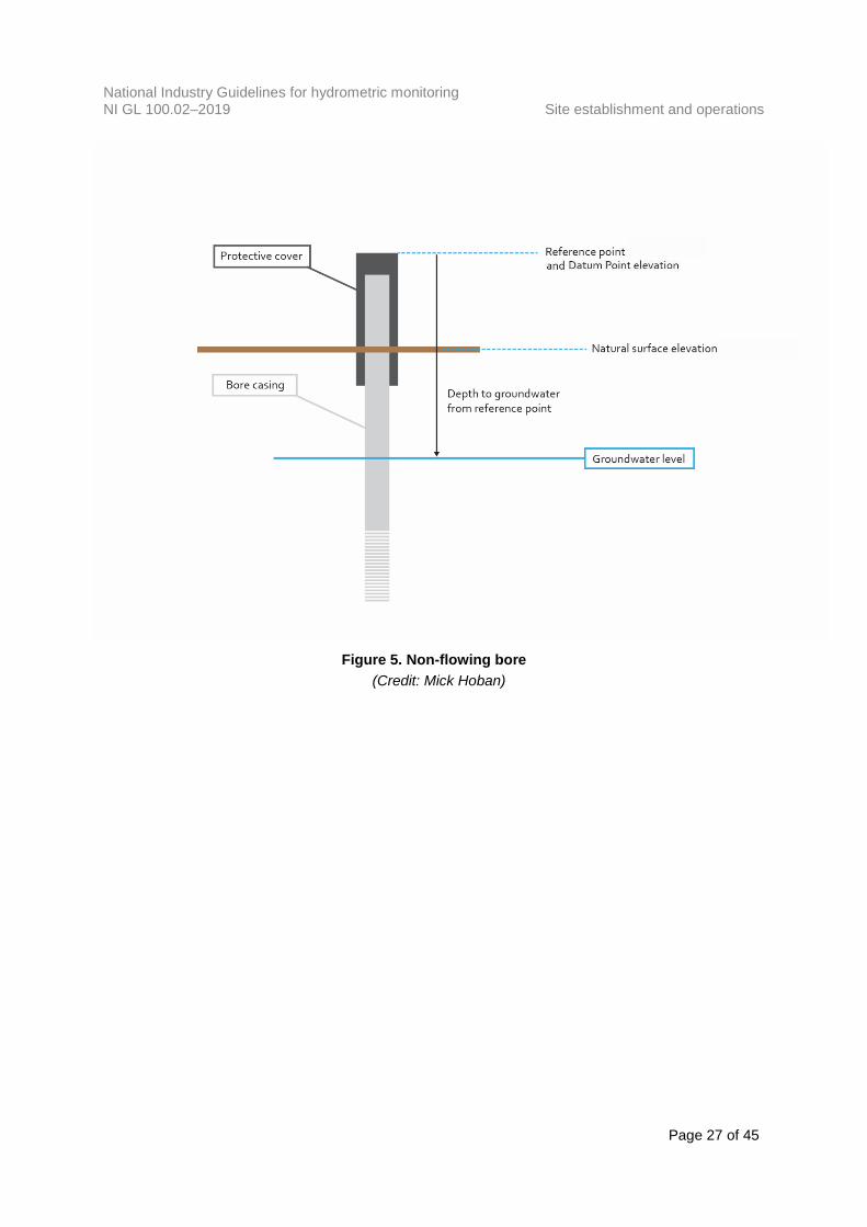
It is imperative that all water level measurements are taken from the correct reference point. In non-flowing bores the reference point may be the top of the protective cover, or the top of the internal casing (Figures 4, 5 and 7). In flowing bores, the reference point may be the artesian pressure connection point at which a pressure reading is recorded (Figure 6). Datum points are points that have a recorded elevation in mAHD. They are used to convert a measured groundwater level to a groundwater elevation in mAHD. Often the datum point and the reference point will be the same point, as shown in Figures 4, 5 and 6. In this case the groundwater elevation can be calculated by subtracting the groundwater level (depth to groundwater) from the datum mAHD elevation (Figure 4). Sometimes the datum point and the reference point are different (e.g., a reference point at top of casing and datum point at the natural surface). In these cases, an offset will need to be applied when calculating the groundwater elevation. The offset will be the distance between the reference point and the datum point. Groundwater level elevation in mAHD may be calculated by subtracting the groundwater level (depth to groundwater) from the datum point elevation plus the offset distance. The reference point and datum point should be recorded with all observations.
4.3.2.2 Data attributes
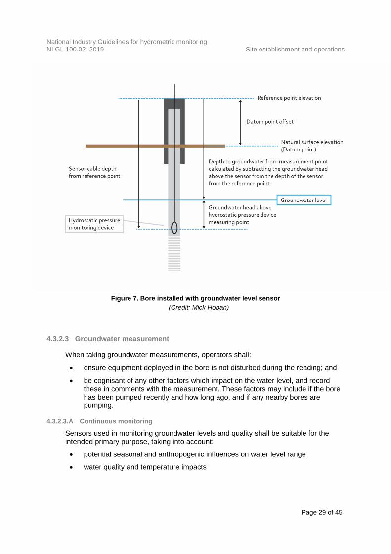
Groundwater levels measured above the reference point shall be recorded as negative values. Groundwater levels measured below the reference point shall be recorded as positive values. Similarly, when the datum point is lower than the reference point the offset shall be recorded as a positive value. When it is higher than the reference point the offset shall be a negative value. Groundwater level can be inferred from a measurement of hydrostatic pressure if the depth of the pressure monitoring point (e.g. a submersible pressure sensor) from the reference point (cable length) is known (Figure 7). The groundwater level below the reference point is recorded as a positive value, the same as a manual dip reading. If the depth to the pressure monitoring point is not known, groundwater level cannot be inferred from the hydrostatic pressure measurement alone.
National Industry Guidelines for hydrometric monitoring NI GL 100.02–2019 Site establishment and operations
Page 26 of 45
Figure 4. Reference points and datum points
Bore 1 has a reference point and a datum point that are at the same point (top of protective cover). To calculate groundwater elevation in Bore 1, subtract groundwater level (depth to groundwater, B) from datum point elevation (A). Bore 2 has a datum point (land surface) that is different to the reference point (top of protective cover). To calculate groundwater elevation in Bore 2, subtract groundwater level (depth to groundwater, B) from the datum point elevation (A) plus the offset distance (C).
(Credit: Mick Hoban)
National Industry Guidelines for hydrometric monitoring NI GL 100.02–2019 Site establishment and operations
Page 27 of 45
Figure 5. Non-flowing bore
(Credit: Mick Hoban)

National Industry Guidelines for hydrometric monitoring NI GL 100.02–2019 Site establishment and operations
Page 28 of 45
Figure 6. Flowing bore
(Credit: Mick Hoban)
National Industry Guidelines for hydrometric monitoring NI GL 100.02–2019 Site establishment and operations
Page 29 of 45
Figure 7. Bore installed with groundwater level sensor
(Credit: Mick Hoban)
4.3.2.3 Groundwater measurement
When taking groundwater measurements, operators shall:
• ensure equipment deployed in the bore is not disturbed during the reading; and
• be cognisant of any other factors which impact on the water level, and record these in comments with the measurement. These factors may include if the bore has been pumped recently and how long ago, and if any nearby bores are pumping.
4.3.2.3.A Continuous monitoring
Sensors used in monitoring groundwater levels and quality shall be suitable for the intended primary purpose, taking into account:
• potential seasonal and anthropogenic influences on water level range
• water quality and temperature impacts
National Industry Guidelines for hydrometric monitoring NI GL 100.02–2019 Site establishment and operations
Page 30 of 45
• installation logistics
• bore construction details
• acceptable measurement uncertainty. Continuous monitoring should be spot checked regularly against manual data. Groundwater level sensor spot checks should be undertaken at a minimum frequency of one spot check per annum. Some instruments (e.g. water quality sensors) may require more frequent spot checks. Refer to manufacturer’s manuals and the organisation’s calibration and spot check records to determine an optimal frequency of test and service. These records shall be retained in the site and instrument history files. Calibration records of reference instruments used to perform spot checks shall be maintained. When using non-vented pressure sensors, appropriate barometric pressure compensation should be applied. The barometric pressure data used in the compensation should be collected within close proximity to the site or sites being monitored.
4.3.2.3.B Manual measurement
Manual measurements are performed to provide fundamental data on the groundwater system. Data collected shall be of sufficient accuracy to meet the intended primary purpose of monitoring. Manual measurements may be taken to: a) make spot checks of water level to validate continuous reading b) validate the total depth of the bore c) measure water level where continuous monitoring is not available. Manual groundwater measurement shall be performed using a calibrated instrument. Manual groundwater level measurement shall, as a minimum, be capable of achieving measurement uncertainties in accordance with ISO 21413:2005. As an example, ISO 21413:2005 states the following measurement uncertainties for water level measurement using an electric tape:
• ±10 mm for depths of less than 60 m
• ±30 mm for depths of around 150 m
• within 150 mm for depths in the range of 500 m. 5 Calibration records for the instrument used to perform manual measurements shall be maintained.
5 Source: ISO 21413:2005. © Standards Australia Limited. Copied by the Australian Government
Bureau of Meteorology with the permission of Standards Australia and Standards New Zealand under Licence 1901-c052.
National Industry Guidelines for hydrometric monitoring NI GL 100.02–2019 Site establishment and operations
Page 31 of 45
4.4 Precipitation sites
The site establishment criteria for continuous monitoring precipitation sites within this guideline are adapted from and consistent with the Australian Bureau of Meteorology’s Observation Specification No. 2013.1 which conforms to or exceeds requirements stipulated by the World Meteorological Organization (WMO). It may not always be possible to meet these criteria, particularly when the primary purpose of a shared site is to measure other parameters such as surface water discharge. Under these circumstances site selection requirements described in other sections may take precedence and govern site selection. If precipitation site criteria are not met, precipitation data for that site will be of reduced scientific acceptability. Exceptions to criteria shall be clearly documented and identified within metadata. To obtain precipitation records that are consistent over time and comparable between sites, standard procedures which apply to all sites shall be written and followed for site establishment and site operations.
4.4.1 Site establishment
4.4.1.1 Selection of sites
4.4.1.1.A General site selection considerations
A preferred site and one or more alternative sites should be selected as the first step. The site selection process shall be documented, and the exposure of the instrumentation to be installed at the site clearly identified. Consideration should be given to the selection of sites where some form of pre-existing security is available.
4.4.1.1.B Representative measurements
The selected site shall be representative of the mean conditions over the area of interest, unless it is intended that the instrument installed is to monitor extreme or specific localised phenomena. For most applications, a precipitation gauge should be located near the geographic centre of the area which it is intended to represent. For mountainous areas, the gauge should be installed at or slightly above the mean altitude of the representative area. Wind is an important consideration when selecting a representative site as wind effects over and around the gauge can greatly alter the amount of precipitation collected. To identify the likelihood of such effects, an assessment of the micro-scale meteorological influences of the area should be performed, taking into account: a) the effects of topography; b) prevailing winds, wind strength and direction(s) from which significant weather is
likely to approach; c) vegetation; and d) current and future land developments and infrastructure.
National Industry Guidelines for hydrometric monitoring NI GL 100.02–2019 Site establishment and operations
Page 32 of 45
The precipitation site should not be located on or close to steep slopes, ridges, cliffs or hollows. Where a site is in an area subject to accumulations of blown sand, silt or salt, the design of the installation should take into account the weather conditions which normally create the accumulations and minimise them.
4.4.1.1.C Environmental considerations
The site should afford some protection against environmental conditions which may cause corrosion, including salt and chemical contamination.
4.4.1.2 Instrument siting
The amount of precipitation collected by a precipitation gauge is affected by a number of factors including those relating to exposure and sheltering of the instrument, height of the gauge orifice and the nature of the ground surface immediately surrounding the instrument. These factors should be taken into consideration when siting and installing a precipitation gauge.
4.4.1.2.A Sheltering and exposure
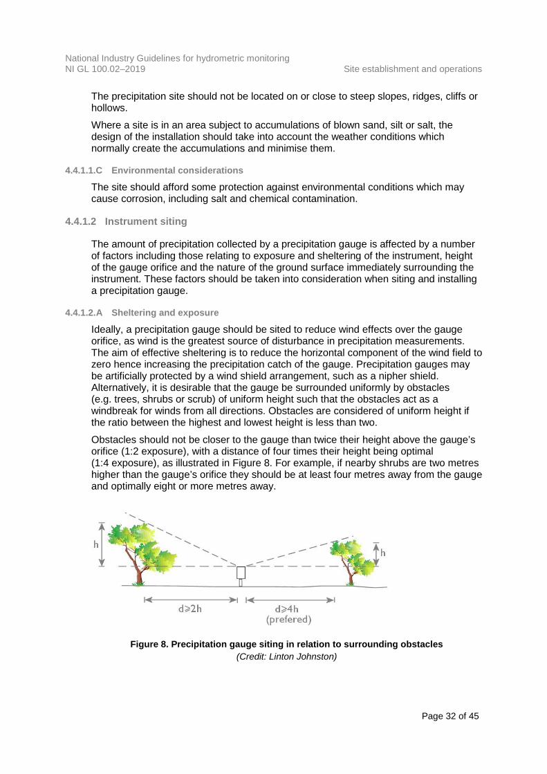
Ideally, a precipitation gauge should be sited to reduce wind effects over the gauge orifice, as wind is the greatest source of disturbance in precipitation measurements. The aim of effective sheltering is to reduce the horizontal component of the wind field to zero hence increasing the precipitation catch of the gauge. Precipitation gauges may be artificially protected by a wind shield arrangement, such as a nipher shield. Alternatively, it is desirable that the gauge be surrounded uniformly by obstacles (e.g. trees, shrubs or scrub) of uniform height such that the obstacles act as a windbreak for winds from all directions. Obstacles are considered of uniform height if the ratio between the highest and lowest height is less than two. Obstacles should not be closer to the gauge than twice their height above the gauge’s orifice (1:2 exposure), with a distance of four times their height being optimal (1:4 exposure), as illustrated in Figure 8. For example, if nearby shrubs are two metres higher than the gauge’s orifice they should be at least four metres away from the gauge and optimally eight or more metres away.
Figure 8. Precipitation gauge siting in relation to surrounding obstacles
(Credit: Linton Johnston)

National Industry Guidelines for hydrometric monitoring NI GL 100.02–2019 Site establishment and operations
Page 33 of 45
In snow prone areas, a site sheltered from the wind as much as possible by obstructions in the middle distance (i.e. in the range of 50 m to 100 m from the gauge) should be chosen. Sheltering and exposure of the instrumentation installed at the site shall be documented by photograph, measurement and sketch North, South, East and West around the instrument. If an artificial wind shield arrangement is in place (such as a nipher shield or equivalent) this shall be documented in metadata. This document is the baseline record of original site sheltering and exposure conditions. After establishment, the sheltering and exposure identification documentation shall be: a) updated whenever the sheltering and exposure of the instruments alters; or b) checked annually.
4.4.1.2.B Height of gauge orifice
The height of the gauge orifice above ground level is a critical factor, which affects the amount of precipitation captured by the gauge. Measured precipitation decreases as the height of the gauge orifice above ground level increases. This is because wind speed increases rapidly with increases in height for the lowest few metres of the atmosphere. Conversely, if a gauge orifice is located too close to the ground, precipitation may splash into the gauge from the ground during heavy to moderate rain. The height of the gauge orifice should therefore be 300 mm above the ground level. Where other constraints render this height impractical, heights of greater than 300 mm may also be accepted provided the reasons are clearly documented and the height above ground level is recorded in site metadata. In general, it is undesirable to locate a precipitation gauge on a fence or pole. However, should a site be found with uniform obstructions over the surrounding area (radius in the order of 50 metres) at a given height, positioning the gauge on a pole that would give the gauge an effective 1:4 exposure above these obstructions may be justified. In snow prone areas the gauge should be mounted above the highest level of accumulated snow for that location. The impact of exposure conditions including height of gauge orifice upon precipitation catch is discussed in Bureau of Meteorology Technical Report 37 by Tauman et al. (1980).
4.4.1.2.C Area surrounding the instrument
The gauge should be mounted such that the surrounding surface (within 1 m) is covered by short grass, or a semi porous, slightly irregular covering such as gravel. Continuous monitoring precipitation sites can experience considerable growth of vegetation between routine maintenance visits, which can adversely affect the readings from gauges mounted close to the ground. In these situations, some form of vegetation suppression growth technique should be used. Hard flat surfaces such as concrete, asphalt and rock should be avoided as this leads to excessive in-splashing. These types of surface may also raise the temperature of the gauge, which may lead to excessive evaporation of the precipitation being captured.
National Industry Guidelines for hydrometric monitoring NI GL 100.02–2019 Site establishment and operations
Page 34 of 45
4.4.1.2.D Measurement of snow fall
The reliable measurement of snow depth has been demonstrated to be highly inaccurate, particularly in regions where wind velocities are high. It becomes almost impossible in blizzard conditions to distinguish between newly fallen snow and snow that has blown from elsewhere. Measurement of snow depth is distinct from measurement of water equivalent of snow. The water equivalent of a snow fall is the amount of liquid precipitation contained in that snow fall. When measuring water equivalent of snow, consideration should be given to the use of specialised weighing gauges or heated gauges, as conventional precipitation gauges may freeze or block with snow. Care should be taken to adjust heating to a level just sufficient to melt the snow as the heating process increases evaporation from the gauge. Consideration should also be given to wind shields to improve the catch effectiveness, such as the Tretyakov shield and Valdai double fence arrangement as described in the World Meteorological Organization publication, International Workshop on Precipitation Measurements (WMO No. 328, 1989). Optical precipitation gauge devices have the potential to measure snowfall more accurately than conventional gauges. These may be mounted on poles to raise them above the worst of the drifting snow. Wind effects are greatly reduced with this type of sensor.
4.4.2 Site operations
4.4.2.1 General requirements
A typical site visit has four main objectives: 1. Observe and maintain good access, security and exposure conditions. 2. Identify any problems with the operation of the site, and determine the quality of
record since the previous visit to identify any problems. 3. Check the calibration of the precipitation gauge and functionality. 4. Carry out routine maintenance to ensure continued good quality record. Local work instructions shall document specific procedures for routine check and service visits. The optimum frequency of routine check and service visits shall be determined and documented based on the purpose for the site and accuracy requirements of the data. Activities shall be scheduled to minimise the drift from acceptable tolerances for parameters measured. Changes to the location and exposure of a precipitation gauge should be avoided to preserve consistency of the precipitation record.
National Industry Guidelines for hydrometric monitoring NI GL 100.02–2019 Site establishment and operations
Page 35 of 45
4.4.2.2 Calibration and spot checks
Calibration procedures and records for precipitation gauges shall be developed and maintained in accordance with requirements detailed in National Industry Guidelines for hydrometric monitoring, Part 3: Instrument and Measurement Systems Management, NI GL 100.03–2019. Procedures for spot checks of precipitation gauges shall be documented, and shall detail methodology, required frequency of checks, tolerances and actions to be followed in the field. Spot check records shall be retained and shall include documentation of any recorded sensor errors, action taken as a result of the spot check, and details of post adjustment spot checks if applicable.
National Industry Guidelines for hydrometric monitoring NI GL 100.02–2019 Appendix A Training
Page 36 of 45
Appendix A Training
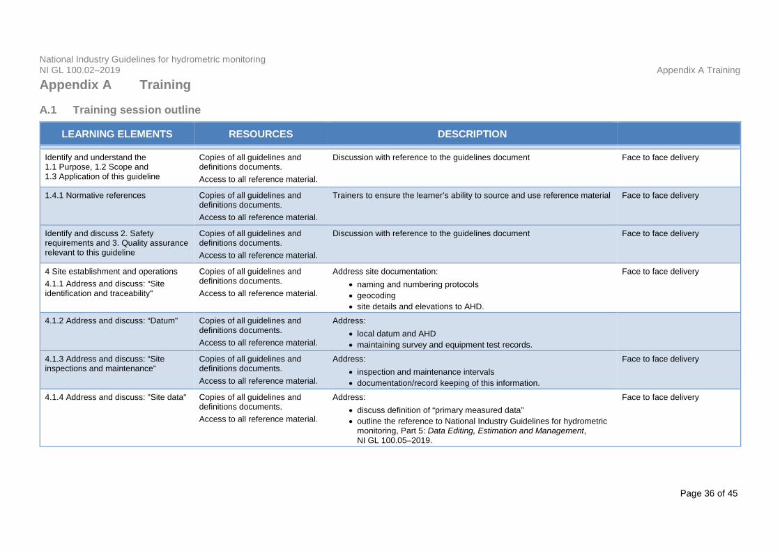
A.1 Training session outline
LEARNING ELEMENTS RESOURCES DESCRIPTION
Identify and understand the 1.1 Purpose, 1.2 Scope and 1.3 Application of this guideline
Copies of all guidelines and definitions documents. Access to all reference material.
Discussion with reference to the guidelines document Face to face delivery
1.4.1 Normative references Copies of all guidelines and definitions documents. Access to all reference material.
Trainers to ensure the learner’s ability to source and use reference material Face to face delivery
Identify and discuss 2. Safety requirements and 3. Quality assurance relevant to this guideline
Copies of all guidelines and definitions documents. Access to all reference material.
Discussion with reference to the guidelines document Face to face delivery
4 Site establishment and operations 4.1.1 Address and discuss: “Site identification and traceability"
Copies of all guidelines and definitions documents. Access to all reference material.
Address site documentation: • naming and numbering protocols • geocoding • site details and elevations to AHD.
Face to face delivery
4.1.2 Address and discuss: “Datum" Copies of all guidelines and definitions documents. Access to all reference material.
Address: • local datum and AHD • maintaining survey and equipment test records.
4.1.3 Address and discuss: “Site inspections and maintenance”
Copies of all guidelines and definitions documents. Access to all reference material.
Address: • inspection and maintenance intervals • documentation/record keeping of this information.
Face to face delivery
4.1.4 Address and discuss: "Site data" Copies of all guidelines and definitions documents. Access to all reference material.
Address: • discuss definition of “primary measured data” • outline the reference to National Industry Guidelines for hydrometric
monitoring, Part 5: Data Editing, Estimation and Management, NI GL 100.05–2019.
Face to face delivery

National Industry Guidelines for hydrometric monitoring NI GL 100.02–2019 Appendix A Training
Page 37 of 45
LEARNING ELEMENTS RESOURCES DESCRIPTION
4.1.5 Address and discuss: "Instrument breakdown and malfunction"
Copies of all guidelines and definitions documents. Access to all reference material.
Explain how to identify the elements of operation that depict a breakdown and/or malfunction of an instrument Address:
• recording of actual versus “outside of tolerance” readings • recording appropriate actions taken and the results of these actions • recording of actions and results, along with all readings in the site
and instrument histories and the dataset.
Face to face delivery
4.1.6 Address and discuss: "Data capture "
Copies of all guidelines and definitions documents. Access to all reference material.
Explain how an organisation should define default intervals Provide example on setting triggers
Face to face delivery
4.1.7 Address and discuss: "Data verification frequency”
Copies of all guidelines and definitions documents. Access to all reference material.
Address: • documenting customer requirements • methods of data verification • keeping of records.
Face to face delivery
4.2 Surface water sites
4.2.1 Site establishment Copies of all guidelines and definitions documents. Access to all reference material.
Address documentation of: • purpose of the site • key features • changes.
Face to face delivery
4.2.1.1 Selection of sites Copies of all guidelines and definitions documents. Access to all reference material.
Provide examples of “primary purpose” Address sections on:
• level/stage monitoring sites • natural controls, artificial weirs, dams • influence of wave action, setup and seiche • discharge monitoring sites • continuous water quality sites.
Face to face delivery
4.2.1.2 Design and construction Copies of all guidelines and definitions documents. Access to all reference material.
Address sections on: • level/stage/discharge monitoring sites • continuous water quality monitoring sites.
Face to face delivery
National Industry Guidelines for hydrometric monitoring NI GL 100.02–2019 Appendix A Training
Page 38 of 45
LEARNING ELEMENTS RESOURCES DESCRIPTION
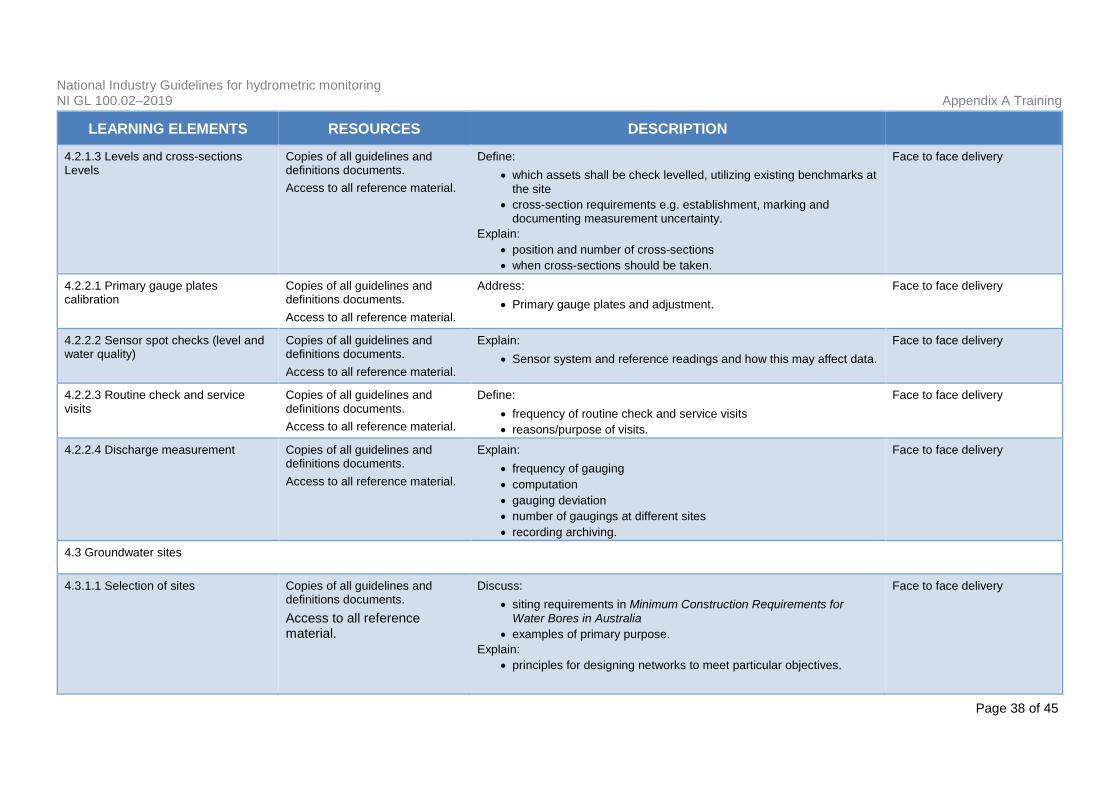
4.2.1.3 Levels and cross-sections Levels
Copies of all guidelines and definitions documents. Access to all reference material.
Define: • which assets shall be check levelled, utilizing existing benchmarks at
the site • cross-section requirements e.g. establishment, marking and
documenting measurement uncertainty. Explain:
• position and number of cross-sections • when cross-sections should be taken.
Face to face delivery
4.2.2.1 Primary gauge plates calibration
Copies of all guidelines and definitions documents. Access to all reference material.
Address: • Primary gauge plates and adjustment.
Face to face delivery
4.2.2.2 Sensor spot checks (level and water quality)
Copies of all guidelines and definitions documents. Access to all reference material.
Explain: • Sensor system and reference readings and how this may affect data.
Face to face delivery
4.2.2.3 Routine check and service visits
Copies of all guidelines and definitions documents. Access to all reference material.
Define: • frequency of routine check and service visits • reasons/purpose of visits.
Face to face delivery
4.2.2.4 Discharge measurement Copies of all guidelines and definitions documents. Access to all reference material.
Explain: • frequency of gauging • computation • gauging deviation • number of gaugings at different sites • recording archiving.
Face to face delivery
4.3 Groundwater sites
4.3.1.1 Selection of sites Copies of all guidelines and definitions documents. Access to all reference material.
Discuss: • siting requirements in Minimum Construction Requirements for
Water Bores in Australia • examples of primary purpose.
Explain: • principles for designing networks to meet particular objectives.
Face to face delivery
National Industry Guidelines for hydrometric monitoring NI GL 100.02–2019 Appendix A Training
Page 39 of 45
LEARNING ELEMENTS RESOURCES DESCRIPTION
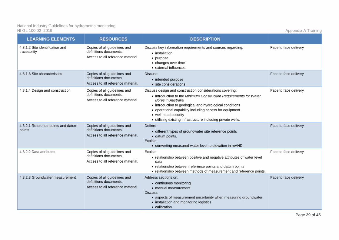
4.3.1.2 Site identification and traceability
Copies of all guidelines and definitions documents. Access to all reference material.
Discuss key information requirements and sources regarding: • installation • purpose • changes over time • external influences.
Face to face delivery
4.3.1.3 Site characteristics Copies of all guidelines and definitions documents. Access to all reference material.
Discuss: • intended purpose • site considerations
Face to face delivery
4.3.1.4 Design and construction Copies of all guidelines and definitions documents. Access to all reference material.
Discuss design and construction considerations covering: • introduction to the Minimum Construction Requirements for Water
Bores in Australia • introduction to geological and hydrological conditions • operational capability including access for equipment • well head security • utilising existing infrastructure including private wells.
Face to face delivery
4.3.2.1 Reference points and datum points
Copies of all guidelines and definitions documents. Access to all reference material.
Define: • different types of groundwater site reference points • datum points.
Explain: • converting measured water level to elevation in mAHD.
Face to face delivery
4.3.2.2 Data attributes Copies of all guidelines and definitions documents. Access to all reference material.
Explain: • relationship between positive and negative attributes of water level
data • relationship between reference points and datum points • relationship between methods of measurement and reference points.
Face to face delivery
4.3.2.3 Groundwater measurement Copies of all guidelines and definitions documents. Access to all reference material.
Address sections on: • continuous monitoring • manual measurement.
Discuss: • aspects of measurement uncertainty when measuring groundwater • installation and monitoring logistics • calibration.
Face to face delivery
National Industry Guidelines for hydrometric monitoring NI GL 100.02–2019 Appendix A Training
Page 40 of 45
LEARNING ELEMENTS RESOURCES DESCRIPTION
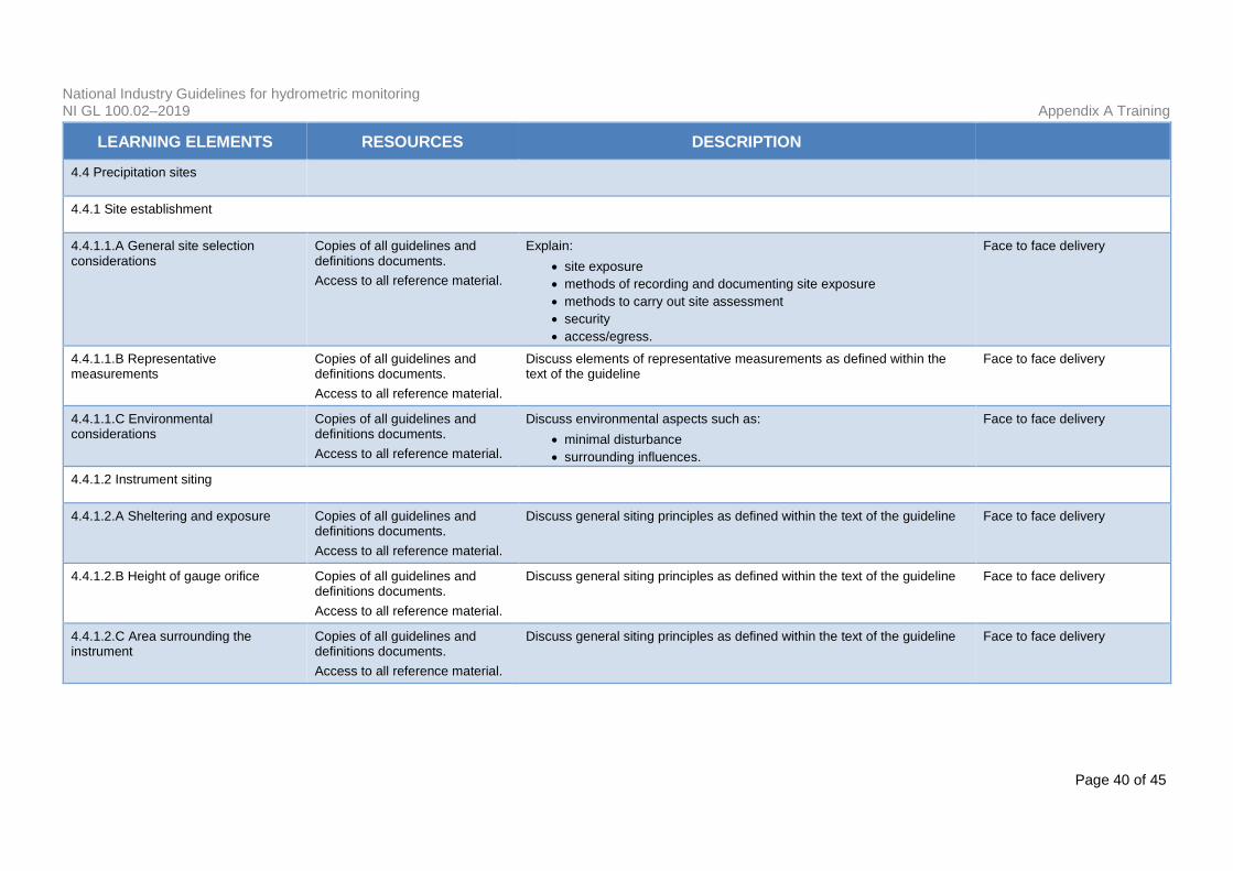
4.4 Precipitation sites
4.4.1 Site establishment
4.4.1.1.A General site selection considerations
Copies of all guidelines and definitions documents. Access to all reference material.
Explain: • site exposure • methods of recording and documenting site exposure • methods to carry out site assessment • security • access/egress.
Face to face delivery
4.4.1.1.B Representative measurements
Copies of all guidelines and definitions documents. Access to all reference material.
Discuss elements of representative measurements as defined within the text of the guideline
Face to face delivery
4.4.1.1.C Environmental considerations
Copies of all guidelines and definitions documents. Access to all reference material.
Discuss environmental aspects such as: • minimal disturbance • surrounding influences.
Face to face delivery
4.4.1.2 Instrument siting
4.4.1.2.A Sheltering and exposure Copies of all guidelines and definitions documents. Access to all reference material.
Discuss general siting principles as defined within the text of the guideline Face to face delivery
4.4.1.2.B Height of gauge orifice Copies of all guidelines and definitions documents. Access to all reference material.
Discuss general siting principles as defined within the text of the guideline Face to face delivery
4.4.1.2.C Area surrounding the instrument
Copies of all guidelines and definitions documents. Access to all reference material.
Discuss general siting principles as defined within the text of the guideline Face to face delivery
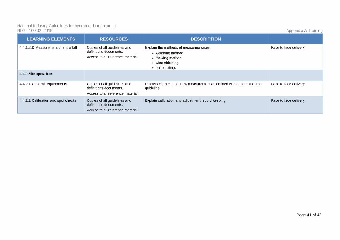
National Industry Guidelines for hydrometric monitoring NI GL 100.02–2019 Appendix A Training
Page 41 of 45
LEARNING ELEMENTS RESOURCES DESCRIPTION
4.4.1.2.D Measurement of snow fall Copies of all guidelines and definitions documents. Access to all reference material.
Explain the methods of measuring snow: • weighing method • thawing method • wind shielding • orifice siting.
Face to face delivery
4.4.2 Site operations
4.4.2.1 General requirements Copies of all guidelines and definitions documents. Access to all reference material.
Discuss elements of snow measurement as defined within the text of the guideline
Face to face delivery
4.4.2.2 Calibration and spot checks Copies of all guidelines and definitions documents. Access to all reference material.
Explain calibration and adjustment record keeping Face to face delivery
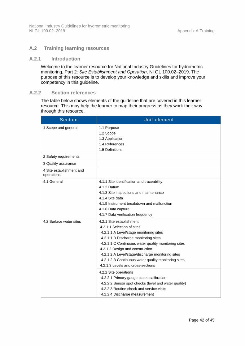
National Industry Guidelines for hydrometric monitoring NI GL 100.02–2019 Appendix A Training
Page 42 of 45
A.2 Training learning resources
A.2.1 Introduction Welcome to the learner resource for National Industry Guidelines for hydrometric monitoring, Part 2: Site Establishment and Operation, NI GL 100.02–2019. The purpose of this resource is to develop your knowledge and skills and improve your competency in this guideline.
A.2.2 Section references The table below shows elements of the guideline that are covered in this learner resource. This may help the learner to map their progress as they work their way through this resource.
Section Unit element 1 Scope and general 1.1 Purpose
1.2 Scope 1.3 Application 1.4 References 1.5 Definitions
2 Safety requirements
3 Quality assurance
4 Site establishment and operations
4.1 General 4.1.1 Site identification and traceability 4.1.2 Datum 4.1.3 Site inspections and maintenance 4.1.4 Site data 4.1.5 Instrument breakdown and malfunction 4.1.6 Data capture 4.1.7 Data verification frequency
4.2 Surface water sites 4.2.1 Site establishment 4.2.1.1 Selection of sites 4.2.1.1.A Level/stage monitoring sites 4.2.1.1.B Discharge monitoring sites 4.2.1.1.C Continuous water quality monitoring sites 4.2.1.2 Design and construction 4.2.1.2.A Level/stage/discharge monitoring sites 4.2.1.2.B Continuous water quality monitoring sites 4.2.1.3 Levels and cross-sections
4.2.2 Site operations 4.2.2.1 Primary gauge plates calibration 4.2.2.2 Sensor spot checks (level and water quality) 4.2.2.3 Routine check and service visits 4.2.2.4 Discharge measurement
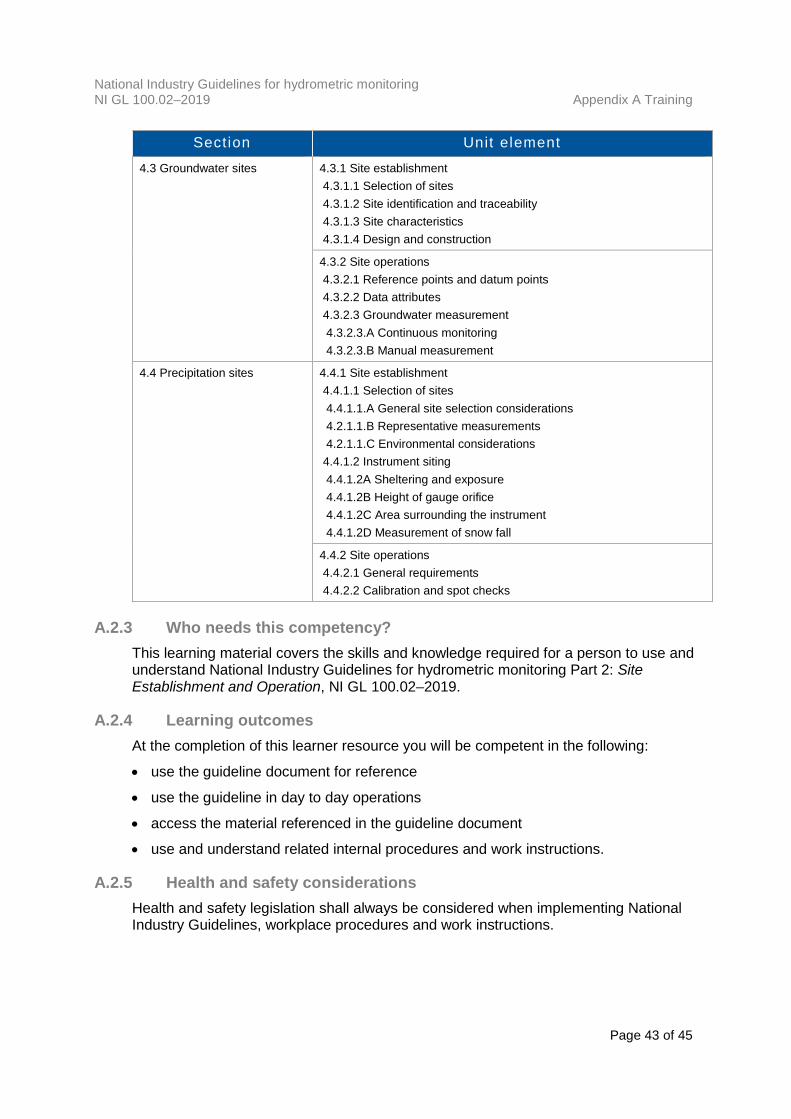
National Industry Guidelines for hydrometric monitoring NI GL 100.02–2019 Appendix A Training
Page 43 of 45
Section Unit element 4.3 Groundwater sites 4.3.1 Site establishment
4.3.1.1 Selection of sites 4.3.1.2 Site identification and traceability 4.3.1.3 Site characteristics 4.3.1.4 Design and construction
4.3.2 Site operations 4.3.2.1 Reference points and datum points 4.3.2.2 Data attributes 4.3.2.3 Groundwater measurement 4.3.2.3.A Continuous monitoring 4.3.2.3.B Manual measurement
4.4 Precipitation sites
4.4.1 Site establishment 4.4.1.1 Selection of sites 4.4.1.1.A General site selection considerations 4.2.1.1.B Representative measurements 4.2.1.1.C Environmental considerations 4.4.1.2 Instrument siting 4.4.1.2A Sheltering and exposure 4.4.1.2B Height of gauge orifice 4.4.1.2C Area surrounding the instrument 4.4.1.2D Measurement of snow fall
4.4.2 Site operations 4.4.2.1 General requirements 4.4.2.2 Calibration and spot checks
A.2.3 Who needs this competency? This learning material covers the skills and knowledge required for a person to use and understand National Industry Guidelines for hydrometric monitoring Part 2: Site Establishment and Operation, NI GL 100.02–2019.
A.2.4 Learning outcomes At the completion of this learner resource you will be competent in the following:
• use the guideline document for reference
• use the guideline in day to day operations
• access the material referenced in the guideline document
• use and understand related internal procedures and work instructions.
A.2.5 Health and safety considerations Health and safety legislation shall always be considered when implementing National Industry Guidelines, workplace procedures and work instructions.

National Industry Guidelines for hydrometric monitoring NI GL 100.02–2019 Appendix A Training
Page 44 of 45
Employees carrying out work related to the National Industry Guidelines should be adequately trained in all relevant health and safety matters.
A.2.6 Environmental considerations Compliance with this guideline may involve working in the environment. As such care should be taken to:
• prevent unnecessary damage to the site environment
• prevent unnecessary disturbance of the natural environment
• carefully construct any infrastructure to minimise impacts on the environment andriver flow conditions
• plan access roads to sites to minimise impacts during all seasonal conditions.
A.2.7 What resources will I need? • Workplace policies and procedures
• Manufacturer manuals, requirements and specifications
• Codes of practice
• Workplace equipment, tools and instruments
• Workplace reports
• Workplace maps, plans and instructions
• Permits and access to locations and worksites.Other useful resources
• Relevant Health and Safety Act
• Safe Work Australia Model Codes of Practice
• Manufacturer’s instruction manuals
• Organisation’s procedures and work instructions
• Herschy, Reginald W., 1985, Streamflow Measurement, Elsevier Applied SciencePublishers, New York, NY, USA
• Australian StandardsWorld Meteorological Organization (WMO)
• World Meteorological Organization 2008, Guide to Hydrological Practices, Volume I:Hydrology – From Measurement to Hydrological Information. WMO-No. 168. Sixthedition, 2008. ISBN 978-92-63-10168-6, viewed 2 October 2018,<http://www.whycos.org/hwrp/guide/index.php>
• World Meteorological Organization 2009, Guide to Hydrological Practices,Volume II: Management of Water Resources and Application of HydrologicalPractices, WMO-No. 168, Sixth edition, 2009, viewed 2 October 2018,<http://www.whycos.org/hwrp/guide/index.php>

National Industry Guidelines for hydrometric monitoring NI GL 100.02–2019 Appendix A Training
Page 45 of 45
• World Meteorological Organization 2010a, Manual on Stream Gauging, Volume I: Fieldwork. WMO-No. 1044, 2010. ISBN 978-92-63-11044-2, viewed 2 October 2018, <http://www.wmo.int/pages/prog/hwrp/manuals.php>
• World Meteorological Organization 2010b, Manual on Stream Gauging, Volume II: Computation of Discharge. WMO-No. 1044, 2010. ISBN 978-92-63-11044-2, viewed 2 October 2018, <http://www.wmo.int/pages/prog/hwrp/manuals.php>