Embed Size (px)
Citation preview
MX240 3D Universal Edge Router
Quick Start
January 2015Part Number: 530-040793Revision 01
This document describes how to install the Juniper Networks®MX2403DUniversal Edge
Router.
Contents MX240 Quick Start Description . . . . . . . . . . . . . . . . . . . . . . . . . . . . . . . . . . . . . . . . . 3
Step 1: Prepare the Site for MX240 Installation . . . . . . . . . . . . . . . . . . . . . . . . . . . . 4
MX240 Rack-Mounting Requirements . . . . . . . . . . . . . . . . . . . . . . . . . . . . . . . 4
Tools Required to Unpack and Prepare the MX240 Router for
Installation . . . . . . . . . . . . . . . . . . . . . . . . . . . . . . . . . . . . . . . . . . . . . . . . . . 5
Step 2: Install the Mounting Hardware in a Four-Post Rack or Cabinet or an
Open-Frame Rack . . . . . . . . . . . . . . . . . . . . . . . . . . . . . . . . . . . . . . . . . . . . . . . . 6
Step 3: Install the Router . . . . . . . . . . . . . . . . . . . . . . . . . . . . . . . . . . . . . . . . . . . . . . 9
Remove Components . . . . . . . . . . . . . . . . . . . . . . . . . . . . . . . . . . . . . . . . . . . . . 9
Install the Router Using a Lift . . . . . . . . . . . . . . . . . . . . . . . . . . . . . . . . . . . . . . 10
Install the Router Without a Mechanical Lift . . . . . . . . . . . . . . . . . . . . . . . . . . 12
Reinstall Components . . . . . . . . . . . . . . . . . . . . . . . . . . . . . . . . . . . . . . . . . . . . 13
Step 4: Connect the Grounding Cable . . . . . . . . . . . . . . . . . . . . . . . . . . . . . . . . . . . 14
Step 5: Connect External Devices and DPC or PIC Cables . . . . . . . . . . . . . . . . . . . 15
Connect to a Network for Out-of-Band Management . . . . . . . . . . . . . . . . . . . 15
Connect a Management Console . . . . . . . . . . . . . . . . . . . . . . . . . . . . . . . . . . . 15
Connect the Line Card Cables . . . . . . . . . . . . . . . . . . . . . . . . . . . . . . . . . . . . . . 15
Step 6: Connect Power Cables . . . . . . . . . . . . . . . . . . . . . . . . . . . . . . . . . . . . . . . . . 17
Connect Power to an AC Router with Normal-Capacity Power Supplies . . . . 17
Connect Power to an AC Router with High-Capacity Power Supplies . . . . . . 18
Connect Power to a DC Router with Normal-Capacity Power Supplies . . . . . 19
Connect Power to a DC Router with High-Capacity Power Supplies . . . . . . . . 21
Step 7: Perform Initial Software Configuration . . . . . . . . . . . . . . . . . . . . . . . . . . . . 23
Enter Configuration Mode . . . . . . . . . . . . . . . . . . . . . . . . . . . . . . . . . . . . . . . . . 23
Configure User Accounts and Passwords . . . . . . . . . . . . . . . . . . . . . . . . . . . . 23
Configure System Attributes . . . . . . . . . . . . . . . . . . . . . . . . . . . . . . . . . . . . . . 24
Commit the Configuration . . . . . . . . . . . . . . . . . . . . . . . . . . . . . . . . . . . . . . . . 24
Safety Warnings . . . . . . . . . . . . . . . . . . . . . . . . . . . . . . . . . . . . . . . . . . . . . . . . . . . . 26
1Copyright © 2015, Juniper Networks, Inc.
Compliance Statements for NEBS . . . . . . . . . . . . . . . . . . . . . . . . . . . . . . . . . . . . . 27
Compliance Statements for EMC Requirements . . . . . . . . . . . . . . . . . . . . . . . . . . 28
Canada . . . . . . . . . . . . . . . . . . . . . . . . . . . . . . . . . . . . . . . . . . . . . . . . . . . . . . . 28
European Community . . . . . . . . . . . . . . . . . . . . . . . . . . . . . . . . . . . . . . . . . . . . 28
Israel . . . . . . . . . . . . . . . . . . . . . . . . . . . . . . . . . . . . . . . . . . . . . . . . . . . . . . . . . 28
Japan . . . . . . . . . . . . . . . . . . . . . . . . . . . . . . . . . . . . . . . . . . . . . . . . . . . . . . . . . 28
United States . . . . . . . . . . . . . . . . . . . . . . . . . . . . . . . . . . . . . . . . . . . . . . . . . . 29
Junos Documentation and Release Notes . . . . . . . . . . . . . . . . . . . . . . . . . . . . . . . 30
Requesting Technical Support . . . . . . . . . . . . . . . . . . . . . . . . . . . . . . . . . . . . . . . . 30
Self-Help Online Tools and Resources . . . . . . . . . . . . . . . . . . . . . . . . . . . . . . 30
Opening a Case with JTAC . . . . . . . . . . . . . . . . . . . . . . . . . . . . . . . . . . . . . . . . . 31
Revision History . . . . . . . . . . . . . . . . . . . . . . . . . . . . . . . . . . . . . . . . . . . . . . . . . . . . . 31
Copyright © 2015, Juniper Networks, Inc.2
MX240 3D Universal Edge Router Quick Start

MX240Quick Start Description
ThisQuick Start contains information you need to install and configure the router quickly.
For complete installation instructions, see theMX2403DUniversal EdgeRouterHardware
Guide at http://www.juniper.net/techpubs/.
WARNING: ThisQuickStart containsasummaryofsafetywarnings in “SafetyWarnings”onpage26. Foracomplete list ofwarnings for this router, includingtranslations, see theMX240 3D Universal Edge Router Hardware Guide athttp://www.juniper.net/techpubs/.
The router is shipped in a cardboard box strapped securely to a wooden pallet. Plastic
straps secure the top and bottom in place. The router chassis is bolted to this pallet.
Quick Start installation instructions and a cardboard accessory box are also included in
the shipping container.
3Copyright © 2015, Juniper Networks, Inc.
MX240 Quick Start Description

Step 1: Prepare the Site for MX240 Installation
• MX240 Rack-Mounting Requirements on page 4
• Tools Required to Unpack and Prepare the MX240 Router for Installation on page 5
MX240 Rack-Mounting Requirements
• You can install the router in a four-post rack or cabinet or an open-frame rack.
• The rack rails must be spaced widely enough to accommodate the router chassis's
external dimensions: 8.71 in. (22.1 cm) high, 24.5 in. (62.2 cm) deep, and
17.45 in. (44.3 cm) wide. Themounting brackets extend the width to 19 in. (48.3 cm).
• The rack must be strong enough to support the weight of the fully configured router,
up to 128 lb (58.1 kg).
• For the cooling system to function properly, the airflow around the chassis must be
unrestricted. Allow at least 6 in. (15.2 cm) of clearance between side-cooled routers.
Allow 2.8 in. (7 cm) between the side of the chassis and any non-heat-producing
surface such as a wall.
• For service personnel to remove and install hardware components, there must be
adequate space at the front and back of the router. Allow at least 30 in. (76.2 cm) in
front of the router and 24 in. (61 cm) behind the router.
• The rack or cabinet must have an adequate supply of cooling air.
• Ensure that the cabinet allows the chassis hot exhaust air to exit from the cabinet
without recirculating into the router.
• The router must be installed into a rack that is secured to the building structure.
• Mount the router at the bottom of the rack if it is the only unit in the rack.
• Whenmounting the router in a partially filled rack, load the rack from the bottom to
the top with the heaviest component at the bottom of the rack.
Copyright © 2015, Juniper Networks, Inc.4
MX240 3D Universal Edge Router Quick Start
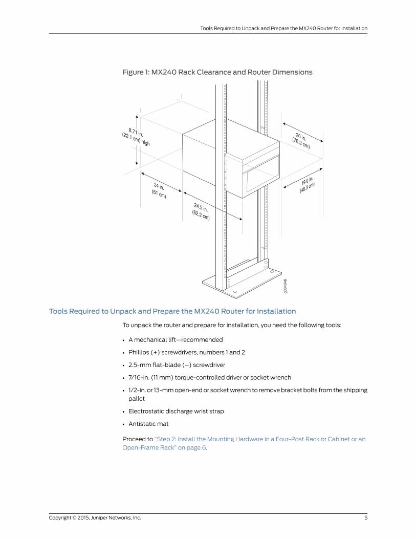
Figure 1: MX240 Rack Clearance and Router Dimensions
Tools Required to Unpack and Prepare theMX240 Router for Installation
To unpack the router and prepare for installation, you need the following tools:
• Amechanical lift—recommended
• Phillips (+) screwdrivers, numbers 1 and 2
• 2.5-mm flat-blade (–) screwdriver
• 7/16-in. (11 mm) torque-controlled driver or socket wrench
• 1/2-in. or 13-mmopen-endor socketwrench to removebracket bolts from the shipping
pallet
• Electrostatic discharge wrist strap
• Antistatic mat
Proceed to “Step 2: Install the Mounting Hardware in a Four-Post Rack or Cabinet or an
Open-Frame Rack” on page 6.
5Copyright © 2015, Juniper Networks, Inc.
Tools Required to Unpack and Prepare the MX240 Router for Installation
Step2: Install theMountingHardware inaFour-PostRackorCabinetoranOpen-FrameRack
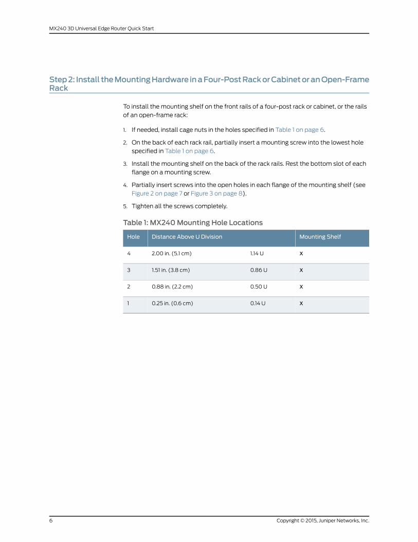
To install the mounting shelf on the front rails of a four-post rack or cabinet, or the rails
of an open-frame rack:
1. If needed, install cage nuts in the holes specified in Table 1 on page 6.
2. On the back of each rack rail, partially insert a mounting screw into the lowest hole
specified in Table 1 on page 6.
3. Install the mounting shelf on the back of the rack rails. Rest the bottom slot of each
flange on amounting screw.
4. Partially insert screws into the open holes in each flange of the mounting shelf (see
Figure 2 on page 7 or Figure 3 on page 8).
5. Tighten all the screws completely.
Table 1: MX240Mounting Hole Locations
Mounting ShelfDistance Above U DivisionHole
X1.14 U2.00 in. (5.1 cm)4
X0.86 U1.51 in. (3.8 cm)3
X0.50 U0.88 in. (2.2 cm)2
X0.14 U0.25 in. (0.6 cm)1
Copyright © 2015, Juniper Networks, Inc.6
MX240 3D Universal Edge Router Quick Start
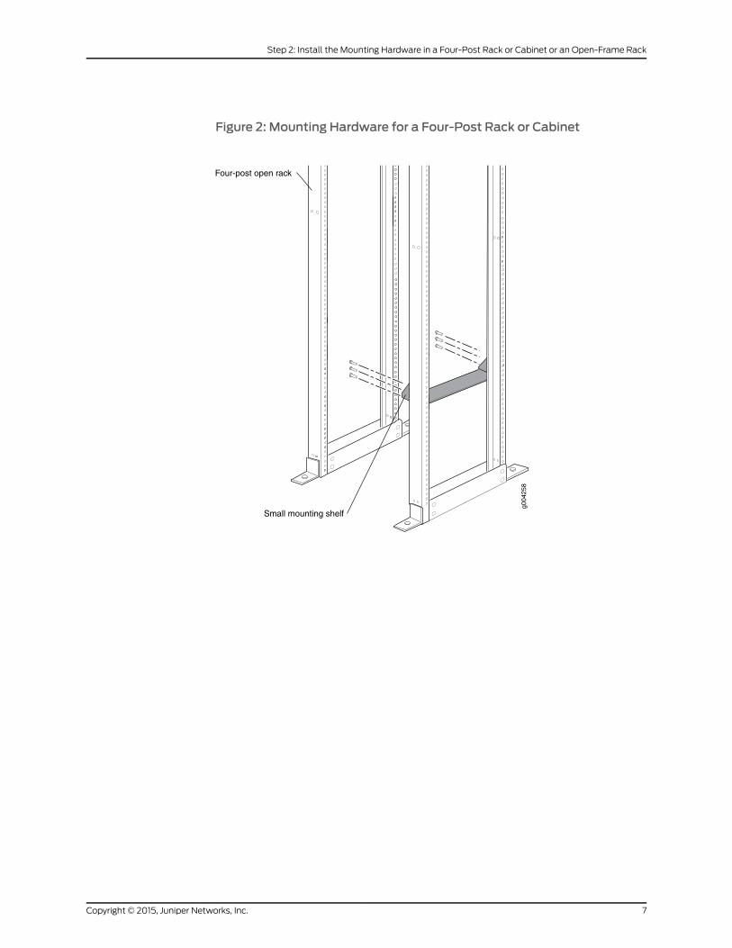
Figure 2: Mounting Hardware for a Four-Post Rack or Cabinet
g004
258
Four-post open rack
Small mounting shelf
7Copyright © 2015, Juniper Networks, Inc.
Step 2: Install the Mounting Hardware in a Four-Post Rack or Cabinet or an Open-Frame Rack
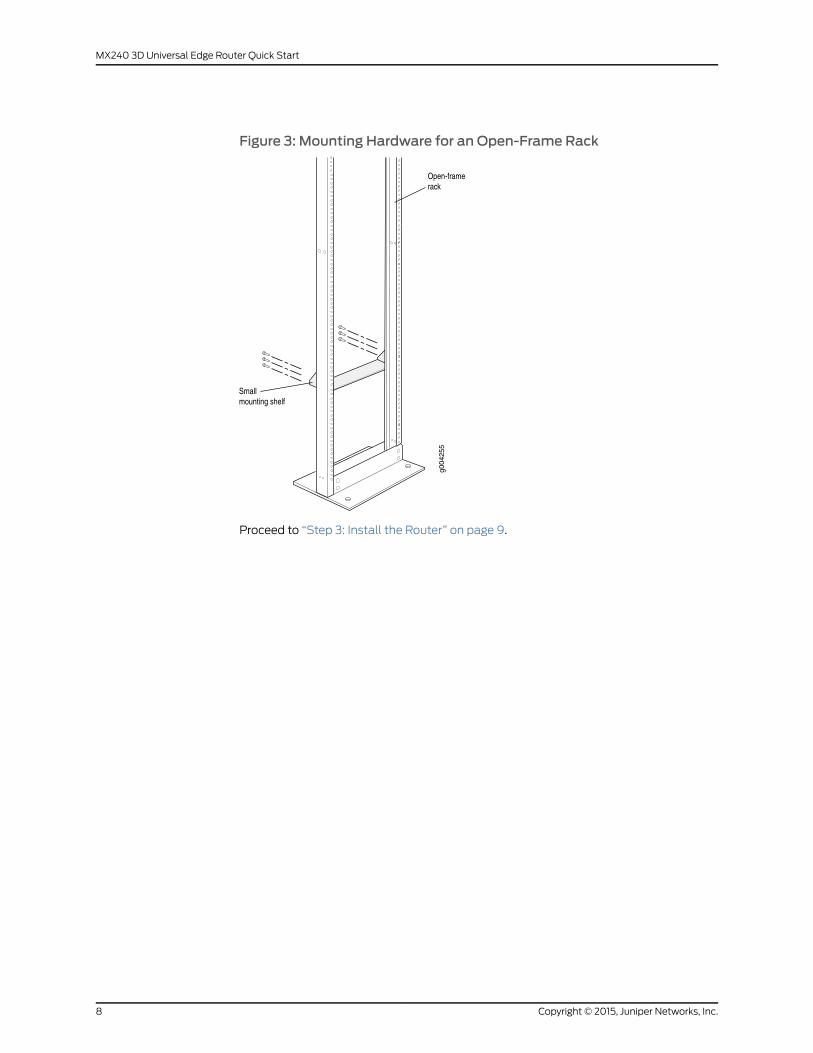
Figure 3: Mounting Hardware for an Open-Frame Rack
Proceed to “Step 3: Install the Router” on page 9.
Copyright © 2015, Juniper Networks, Inc.8
MX240 3D Universal Edge Router Quick Start
Step 3: Install the Router
Becauseof the router's sizeandweight, youmust removeall componentsbefore installing
the router. We also recommend that you install the router using amechanical lift.
• Remove Components on page 9
• Install the Router Using a Lift on page 10
• Install the Router Without a Mechanical Lift on page 12
• Reinstall Components on page 13
Remove Components
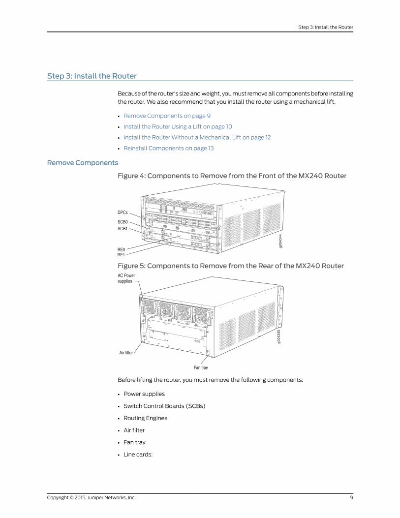
Figure 4: Components to Remove from the Front of theMX240 Router
Figure 5: Components to Remove from the Rear of theMX240 Router
Before lifting the router, you must remove the following components:
• Power supplies
• Switch Control Boards (SCBs)
• Routing Engines
• Air filter
• Fan tray
• Line cards:
9Copyright © 2015, Juniper Networks, Inc.
Step 3: Install the Router
• Dense Port Concentrators (DPCs)
• Flexible PIC Concentrators (FPCs)
• Physical Interface Cards (PICs)
• Modular Port Concentrators (MPCs)
• Modular Interface Cards (MICs)
To remove the components from the router:
1. Slide each component out of the chassis evenly so that it does not become stuck or
damaged.
2. Label each component as you remove it so you can reinstall it in the correct location.
3. Immediately store each removed component in an electrostatic bag.
4. Do not stack removed components. Lay each one on a flat surface.
NOTE: For complete instructions on removing router components, see“Installing theMX240Chassis in theRackManually” in theMX2403DUniversalEdge Router Hardware Guide.
Install the Router Using a Lift
To install the router using a lift:
1. Ensure that the rack is in its permanent location and is secured to the building. Ensure
that the installation site allowsadequate clearance for bothairflowandmaintenance.
For details, see theMX240 3D Universal Edge Router Hardware Guide.
2. Load the router onto the lift, making sure it rests securely on the lift platform (see
Figure 6 on page 11).
Copyright © 2015, Juniper Networks, Inc.10
MX240 3D Universal Edge Router Quick Start
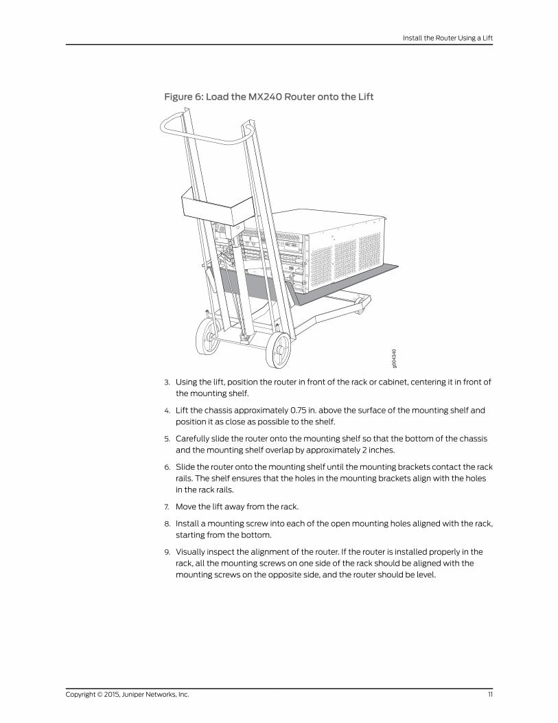
Figure 6: Load theMX240 Router onto the Lift
3. Using the lift, position the router in front of the rack or cabinet, centering it in front of
the mounting shelf.
4. Lift the chassis approximately 0.75 in. above the surface of the mounting shelf and
position it as close as possible to the shelf.
5. Carefully slide the router onto the mounting shelf so that the bottom of the chassis
and themounting shelf overlap by approximately 2 inches.
6. Slide the router onto themounting shelf until themounting brackets contact the rack
rails. The shelf ensures that the holes in the mounting brackets align with the holes
in the rack rails.
7. Move the lift away from the rack.
8. Install a mounting screw into each of the openmounting holes aligned with the rack,
starting from the bottom.
9. Visually inspect the alignment of the router. If the router is installed properly in the
rack, all the mounting screws on one side of the rack should be aligned with the
mounting screws on the opposite side, and the router should be level.
11Copyright © 2015, Juniper Networks, Inc.
Install the Router Using a Lift
Install the RouterWithout aMechanical Lift
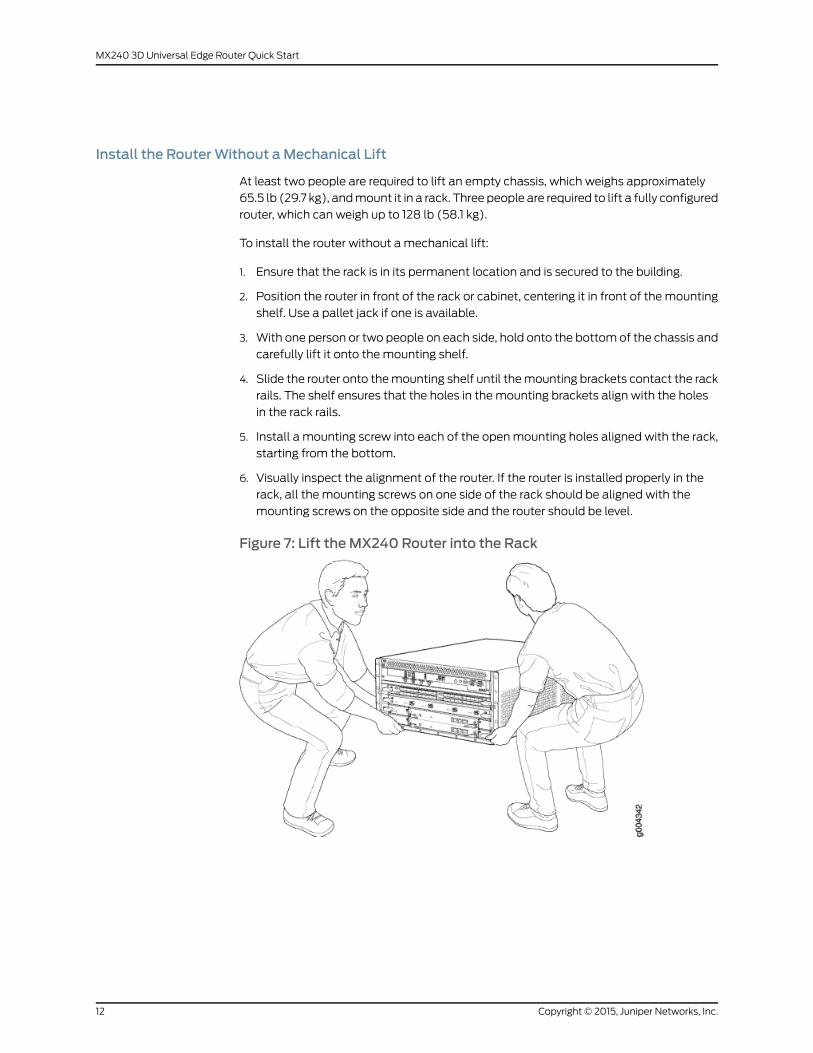
At least two people are required to lift an empty chassis, which weighs approximately
65.5 lb (29.7 kg), andmount it in a rack. Three people are required to lift a fully configured
router, which can weigh up to 128 lb (58.1 kg).
To install the router without a mechanical lift:
1. Ensure that the rack is in its permanent location and is secured to the building.
2. Position the router in front of the rack or cabinet, centering it in front of the mounting
shelf. Use a pallet jack if one is available.
3. With one person or two people on each side, hold onto the bottom of the chassis and
carefully lift it onto the mounting shelf.
4. Slide the router onto themounting shelf until themounting brackets contact the rack
rails. The shelf ensures that the holes in the mounting brackets align with the holes
in the rack rails.
5. Install a mounting screw into each of the openmounting holes aligned with the rack,
starting from the bottom.
6. Visually inspect the alignment of the router. If the router is installed properly in the
rack, all the mounting screws on one side of the rack should be aligned with the
mounting screws on the opposite side and the router should be level.
Figure 7: Lift theMX240 Router into the Rack
Copyright © 2015, Juniper Networks, Inc.12
MX240 3D Universal Edge Router Quick Start
Reinstall Components
To reinstall the components in the router:
1. Slide each component into the chassis evenly so that it does not become stuck or
damaged.
2. Tighten the captive screws for each component.
NOTE: Make sure that all empty slots are covered with a blank panel beforeoperating the router.
Proceed to “Step 4: Connect the Grounding Cable” on page 14.
13Copyright © 2015, Juniper Networks, Inc.
Reinstall Components

Step 4: Connect the Grounding Cable
1. Attachanelectrostaticdischarge (ESD)groundingstrap toyourbarewrist, andconnect
the strap to an approved site ESD grounding point. See the instructions for your site.
2. Connect the grounding cable to a proper earth ground.
3. Verify that a licensed electrician has attached the cable lug provided with the router
to the grounding cable.
4. Make sure that grounding surfaces are clean and brought to a bright finish before
grounding connections are made.
5. Attachanelectrostaticdischarge (ESD)groundingstrap toyourbarewrist, andconnect
the strap to one of the ESD points on the chassis. For more information about ESD,
see theMX240 Ethernet Services Router Hardware Guide
6. Place the grounding cable lug over the grounding points.point on the top rear of the
chassis. The grounding point is sized for UNC 1/4-20 bolts.
7. Secure the grounding cable lug to the grounding points, first with the washers, then
with the screws.
8. Verify that the grounding cabling is correct, that the grounding cable does not touch
or block access to router components, and that it does not drapewhere people could
trip on it.
Proceed to “Step 5: Connect External Devices and DPC or PIC Cables” on page 15.
Copyright © 2015, Juniper Networks, Inc.14
MX240 3D Universal Edge Router Quick Start
Step 5: Connect External Devices and DPC or PIC Cables
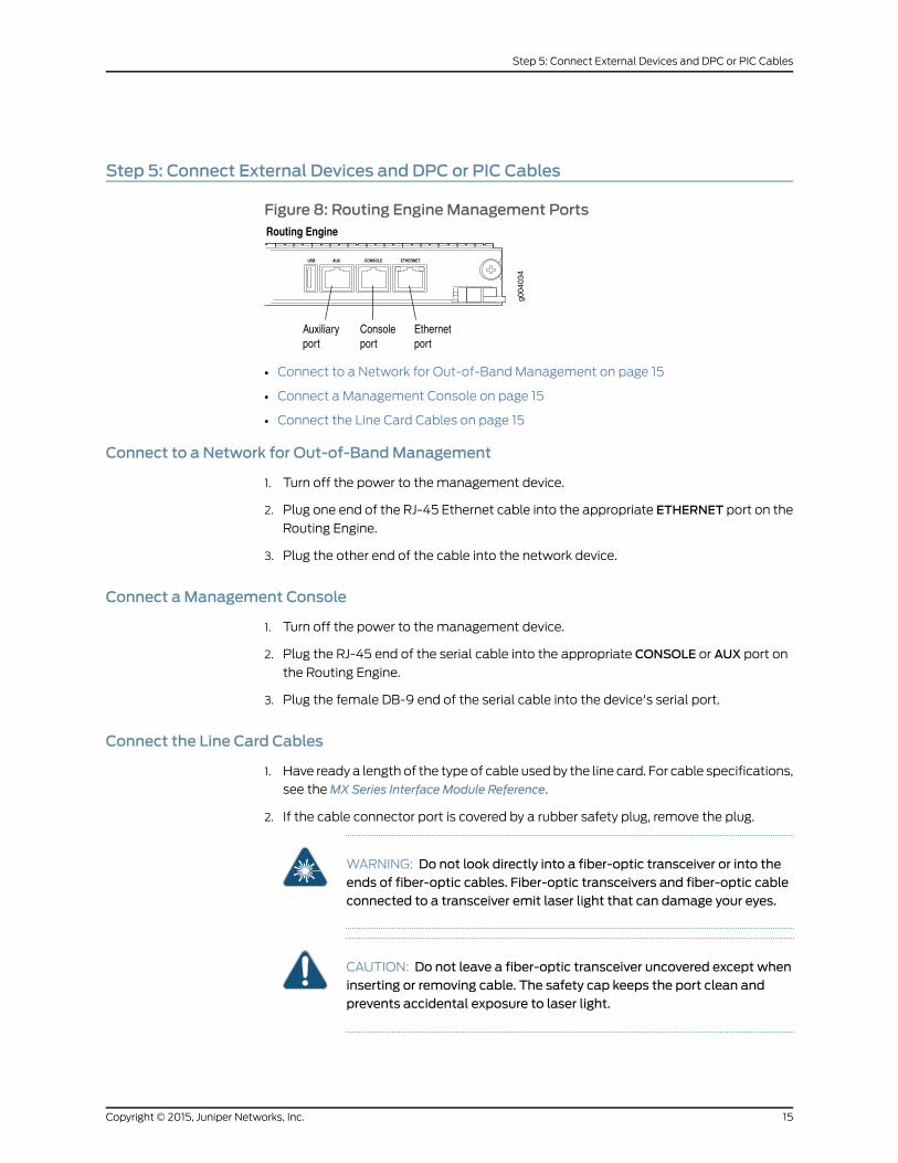
Figure 8: Routing EngineManagement Ports
• Connect to a Network for Out-of-Band Management on page 15
• Connect a Management Console on page 15
• Connect the Line Card Cables on page 15
Connect to a Network for Out-of-BandManagement
1. Turn off the power to the management device.
2. Plug one end of the RJ-45 Ethernet cable into the appropriate ETHERNET port on the
Routing Engine.
3. Plug the other end of the cable into the network device.
Connect aManagement Console
1. Turn off the power to the management device.
2. Plug the RJ-45 end of the serial cable into the appropriate CONSOLE or AUX port on
the Routing Engine.
3. Plug the female DB-9 end of the serial cable into the device's serial port.
Connect the Line Card Cables
1. Have ready a length of the type of cable usedby the line card. For cable specifications,
see theMX Series Interface Module Reference.
2. If the cable connector port is covered by a rubber safety plug, remove the plug.
WARNING: Do not look directly into a fiber-optic transceiver or into theends of fiber-optic cables. Fiber-optic transceivers and fiber-optic cableconnected to a transceiver emit laser light that can damage your eyes.
CAUTION: Do not leave a fiber-optic transceiver uncovered except wheninserting or removing cable. The safety cap keeps the port clean andprevents accidental exposure to laser light.
15Copyright © 2015, Juniper Networks, Inc.
Step 5: Connect External Devices and DPC or PIC Cables
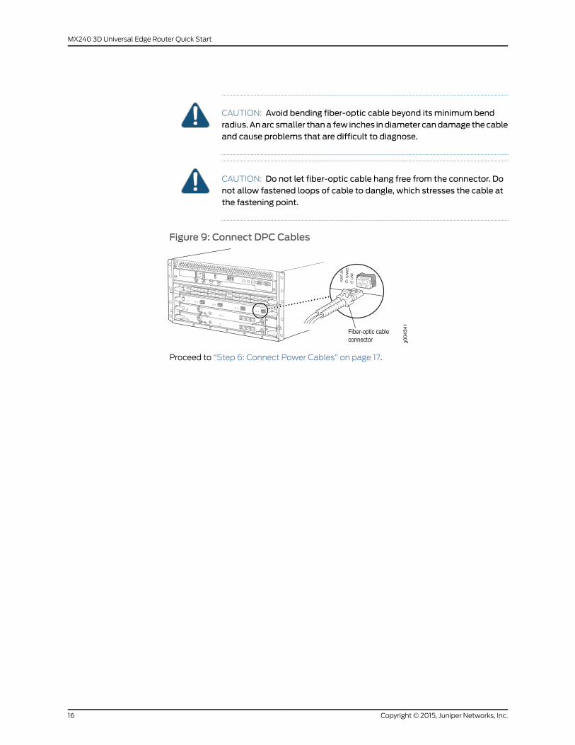
CAUTION: Avoid bending fiber-optic cable beyond its minimum bendradius.Anarc smaller thana few inches indiameter candamage thecableand cause problems that are difficult to diagnose.
CAUTION: Do not let fiber-optic cable hang free from the connector. Donot allow fastened loops of cable to dangle, which stresses the cable atthe fastening point.
Figure 9: Connect DPC Cables
Proceed to “Step 6: Connect Power Cables” on page 17.
Copyright © 2015, Juniper Networks, Inc.16
MX240 3D Universal Edge Router Quick Start
Step 6: Connect Power Cables
Dependingonyour configuration, your router useseithernormal-capacityorhigh-capacity
AC or DC power supplies. Perform the appropriate procedures for each power supply in
your router.
WARNING: Youmust ground the router before connecting either the ACpower cord or the DC power cables.
• Connect Power to an AC Router with Normal-Capacity Power Supplies on page 17
• Connect Power to an AC Router with High-Capacity Power Supplies on page 18
• Connect Power to a DC Router with Normal-Capacity Power Supplies on page 19
• Connect Power to a DC Router with High-Capacity Power Supplies on page 21
Connect Power to an AC Router with Normal-Capacity Power Supplies
WARNING: The router must be properly grounded before you connect theAC power cords.
1. Attachanelectrostaticdischarge (ESD)groundingstrap toyourbarewrist, andconnect
the strap to one of the ESD points on the chassis. For more information about ESD,
see theMX240 3D Universal Edge Router Hardware Guide.
2. Locate the power cords, which should have a plug appropriate for your geographical
location. See theMX240 3D Universal Edge Router Hardware Guide.
3. Move the circuit breaker on the power supply faceplate to the off position (O).
4. Insert the appliance coupler end of the power cord into the appliance inlet on the
power supply.
5. Insert the power cord plug into an external AC power source receptacle.
NOTE: Each power supply must be connected to a dedicated AC powerfeed and a dedicated customer site circuit breaker. We recommend thatyou use aminimum, or as permitted by local code.
6. Dress the power cord appropriately. Verify that the power cord does not block the air
exhaust and access to router components, or drape where people could trip on it.
7. Repeat Step 2 through Step 6 for the remaining power supplies.
8. Switch the AC switch on each power supply to the on position (—) and observe the
statusLEDsoneachpower supply faceplate. If anACpower supply is correctly installed
and functioning normally, the ACOK and DCOK LEDs light steadily, and the PS FAIL
LED is not lit.
17Copyright © 2015, Juniper Networks, Inc.
Step 6: Connect Power Cables
If any of the status LEDs indicates that the power supply is not functioning normally,
repeat the installation and cabling procedures.
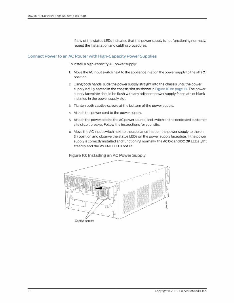
Connect Power to an AC Router with High-Capacity Power Supplies
To install a high-capacity AC power supply:
1. Move theAC input switchnext to theappliance inlet on thepower supply to theoff (O)
position.
2. Using both hands, slide the power supply straight into the chassis until the power
supply is fully seated in the chassis slot as shown in Figure 10 on page 18. The power
supply faceplate should be flush with any adjacent power supply faceplate or blank
installed in the power supply slot.
3. Tighten both captive screws at the bottom of the power supply.
4. Attach the power cord to the power supply.
5. Attach the power cord to theACpower source, and switch on the dedicated customer
site circuit breaker. Follow the instructions for your site.
6. Move the AC input switch next to the appliance inlet on the power supply to the on
(|) position and observe the status LEDs on the power supply faceplate. If the power
supply is correctly installed and functioning normally, theACOK andDCOK LEDs light
steadily and the PS FAIL LED is not lit.
Figure 10: Installing an AC Power Supply
Copyright © 2015, Juniper Networks, Inc.18
MX240 3D Universal Edge Router Quick Start
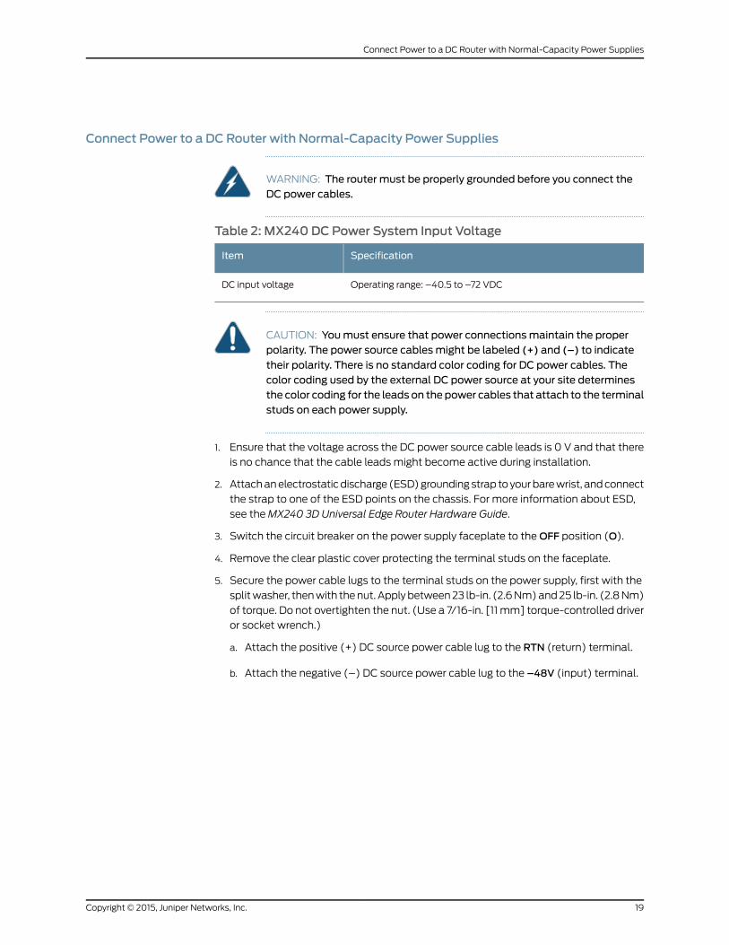
Connect Power to a DC Router with Normal-Capacity Power Supplies
WARNING: The router must be properly grounded before you connect theDC power cables.
Table 2: MX240 DC Power System Input Voltage
SpecificationItem
Operating range: –40.5 to –72 VDCDC input voltage
CAUTION: Youmust ensure that power connectionsmaintain the properpolarity. The power source cablesmight be labeled (+) and (–) to indicate
their polarity. There is no standard color coding for DC power cables. Thecolor coding used by the external DC power source at your site determinesthe color coding for the leads on the power cables that attach to the terminalstuds on each power supply.
1. Ensure that the voltage across the DC power source cable leads is 0 V and that there
is no chance that the cable leads might become active during installation.
2. Attachanelectrostaticdischarge (ESD)groundingstrap toyourbarewrist, andconnect
the strap to one of the ESD points on the chassis. For more information about ESD,
see theMX240 3D Universal Edge Router Hardware Guide.
3. Switch the circuit breaker on the power supply faceplate to theOFF position (O).
4. Remove the clear plastic cover protecting the terminal studs on the faceplate.
5. Secure the power cable lugs to the terminal studs on the power supply, first with the
splitwasher, thenwith thenut. Applybetween23 lb-in. (2.6Nm)and25 lb-in. (2.8Nm)
of torque. Do not overtighten the nut. (Use a 7/16-in. [11 mm] torque-controlled driver
or socket wrench.)
a. Attach the positive (+) DC source power cable lug to the RTN (return) terminal.
b. Attach the negative (–) DC source power cable lug to the –48V (input) terminal.
19Copyright © 2015, Juniper Networks, Inc.
Connect Power to a DC Router with Normal-Capacity Power Supplies
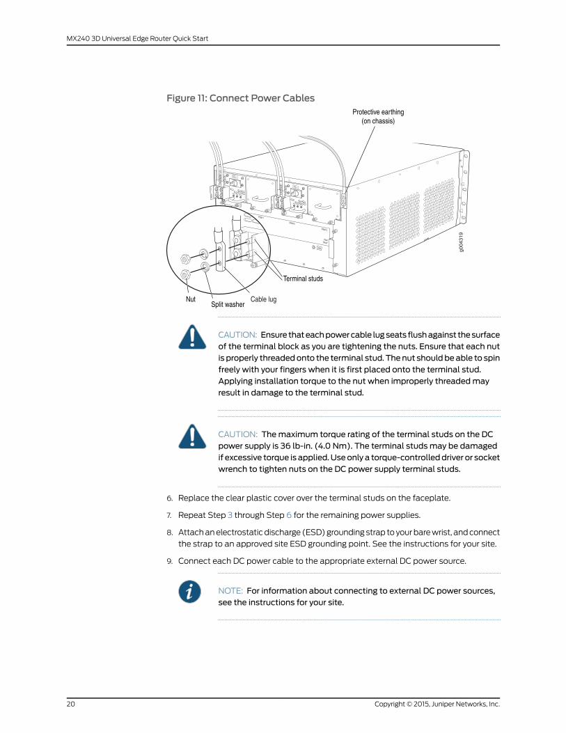
Figure 11: Connect Power Cables
CAUTION: Ensure thateachpowercable lugseats flushagainst thesurfaceof the terminal block as you are tightening the nuts. Ensure that each nutis properly threadedonto the terminal stud. Thenut shouldbeable to spinfreely with your fingers when it is first placed onto the terminal stud.Applying installation torque to the nut when improperly threadedmayresult in damage to the terminal stud.
CAUTION: Themaximum torque rating of the terminal studs on the DCpower supply is 36 lb-in. (4.0 Nm). The terminal studsmay be damagedif excessive torque is applied.Useonlya torque-controlleddriver or socketwrench to tighten nuts on the DC power supply terminal studs.
6. Replace the clear plastic cover over the terminal studs on the faceplate.
7. Repeat Step 3 through Step 6 for the remaining power supplies.
8. Attachanelectrostaticdischarge (ESD)groundingstrap toyourbarewrist, andconnect
the strap to an approved site ESD grounding point. See the instructions for your site.
9. Connect each DC power cable to the appropriate external DC power source.
NOTE: For information about connecting to external DC power sources,see the instructions for your site.
Copyright © 2015, Juniper Networks, Inc.20
MX240 3D Universal Edge Router Quick Start
10. Switch on the external circuit breakers to provide voltage to the DC power source
cable leads.
11. Switch on the circuit breakers on each power supply to theON position (|).Observe
the status LEDs on each power supply faceplate. If a DC power supply is correctly
installed and functioning normally, the PWROK, BRKRON, and INPUTOK LEDs light
green steadily.
Proceed to “Step 7: Perform Initial Software Configuration” on page 23.
Connect Power to a DC Router with High-Capacity Power Supplies
To install a DC power supply:
1. Ensure that the voltage across the DC power source cable leads is 0 V and that there
is no chance that the cable leads might become active during installation.
2. Move the power switch on the power supply faceplate to the off (O) position.
3. Using both hands, slide the power supply straight into the chassis until the power
supply is fully seated in the chassis slot. The power supply faceplate should be flush
with any adjacent power supply faceplate or blank installed in the power supply slot.
4. Using a screwdriver, loosen the captive screw holding the metal cover over the input
mode switch. Rotate themetal cover away from the inputmode switch to expose the
switch.
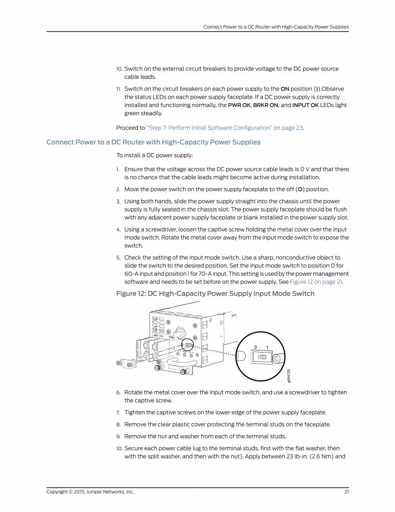
5. Check the setting of the input mode switch. Use a sharp, nonconductive object to
slide the switch to the desired position. Set the input mode switch to position 0 for
60-A inputandposition 1 for 70-A input. This setting is usedby thepowermanagement
software and needs to be set before on the power supply. See Figure 12 on page 21.
Figure 12: DC High-Capacity Power Supply Input Mode Switchg0
0472
5
6. Rotate the metal cover over the input mode switch, and use a screwdriver to tighten
the captive screw.
7. Tighten the captive screws on the lower edge of the power supply faceplate.
8. Remove the clear plastic cover protecting the terminal studs on the faceplate.
9. Remove the nut and washer from each of the terminal studs.
10. Secure each power cable lug to the terminal studs, first with the flat washer, then
with the split washer, and then with the nut). Apply between 23 lb-in. (2.6 Nm) and
21Copyright © 2015, Juniper Networks, Inc.
Connect Power to a DC Router with High-Capacity Power Supplies
25 lb-in. (2.8 Nm) of torque to each nut. Do not overtighten the nut. (Use a 7/16-in.
[11 mm] torque-controlled driver or socket wrench.)
a. Secure the positive (+) DC source power cable lug to the RTN (return) terminal.
b. Secure the negative (–) DC source power cable lug to the –48V (input) terminal.
CAUTION: Ensure thateachpowercable lugseats flushagainst thesurfaceof the terminal block as you are tightening the nuts. Ensure that each nutis properly threadedonto the terminal stud. Thenut shouldbeable to spinfreely with your fingers when it is first placed onto the terminal stud.Applying installation torque to the nut when improperly threadedmayresult in damage to the terminal stud.
CAUTION: Themaximum torque rating of the terminal studs on the DCpower supply is 36 lb-in. (4.0 Nm). The terminal studsmay be damagedif excessive torque is applied.Useonlya torque-controlleddriver or socketwrench to tighten nuts on the DC power supply terminal studs.
NOTE: The DC power supplies in PEM0 and PEM1must be powered by
dedicated power feeds derived from feed A, and the DC power supplies
in PEM2 and PEM3must be powered by dedicated power feeds derived
fromfeedB. This configurationprovides thecommonlydeployedA/B feed
redundancy for the system.
11. Replace the clear plastic cover over the terminal studs on the faceplate.
12. Route the power cables along the cable restraint toward the left or right corner of the
chassis. If needed to hold the power cables in place, thread plastic cable ties, which
youmust provide, through the openings on the cable restraint.
13. Verify that the power cabling is correct, that the cables are not touching or blocking
access to router components, and that they do not drape where people could trip on
them.
14. Switch on the dedicated customer site circuit breakers. Follow your site's procedures
for safety and ESD.
Verify that the INPUTOK LED on the power supply is lit green.
15. On each of the DC power supplies, turn the power switch to the on (—) position.
Observe the statusLEDson thepower supply faceplate. If thepower supply is correctly
installed and functioning normally, the PWROK, BRKRON, and INPUTOK LEDs light
green steadily.
Proceed to “Step 7: Perform Initial Software Configuration” on page 23.
Copyright © 2015, Juniper Networks, Inc.22
MX240 3D Universal Edge Router Quick Start
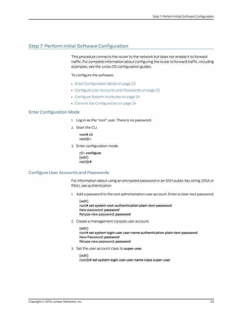
Step 7: Perform Initial Software Configuration
This procedure connects the router to the network but does not enable it to forward
traffic. For complete information about configuring the router to forward traffic, including
examples, see the Junos OS configuration guides.
To configure the software:
• Enter Configuration Mode on page 23
• Configure User Accounts and Passwords on page 23
• Configure System Attributes on page 24
• Commit the Configuration on page 24
Enter ConfigurationMode
1. Log in as the “root” user. There is no password.
2. Start the CLI.
root# cliroot@>
3. Enter configuration mode.
cli> configure[edit]root@#
Configure User Accounts and Passwords
For information about using an encrypted password or an SSH public key string (DSA or
RSA), see authentication.
1. Add a password to the root administration user account. Enter a clear-text password.
[edit]root# set system root-authentication plain-text-passwordNew password: passwordRetype new password: password
2. Create amanagement console user account.
[edit]root# set system login user user-name authentication plain-text-passwordNew Password: passwordRetype new password: password
3. Set the user account class to super-user.
[edit]root@# set system login user user-name class super-user
23Copyright © 2015, Juniper Networks, Inc.
Step 7: Perform Initial Software Configuration

Configure SystemAttributes
1. Configure the name of the router. If the name includes spaces, enclose the name in
quotation marks (“ ”).
[edit]root@# set system host-name host-name
2. Configure the router's domain name.
[edit]root@# set system domain-name domain-name
3. Configure the IP address and prefix length for the router's Ethernet interface.
[edit]root@# set interfaces fxp0 unit 0 family inet address address/prefix-length
4. Configure the IP address of a backup router, which is used only while the routing
protocol is not running.
[edit]root@# set system backup-router address
5. Configure the IP address of a DNS server.
[edit]root@# set system name-server address
Commit the Configuration
1. Optionally, display the configuration to verify that it is correct.
[edit]root@# showsystem {host-name host-name;domain-name domain-name;backup-router address;root-authentication {authentication-method (password | public-key);
}name-server {address;
}}interfaces {fxp0 {unit 0 {family inet {address address/prefix-length;
}}
}}
2. Commit the configuration to activate it on the router.
Copyright © 2015, Juniper Networks, Inc.24
MX240 3D Universal Edge Router Quick Start
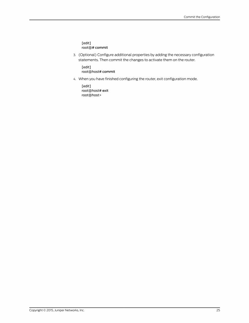
[edit]root@# commit
3. (Optional) Configure additional properties by adding the necessary configuration
statements. Then commit the changes to activate them on the router.
[edit]root@host# commit
4. When you have finished configuring the router, exit configuration mode.
[edit]root@host# exitroot@host>
25Copyright © 2015, Juniper Networks, Inc.
Commit the Configuration
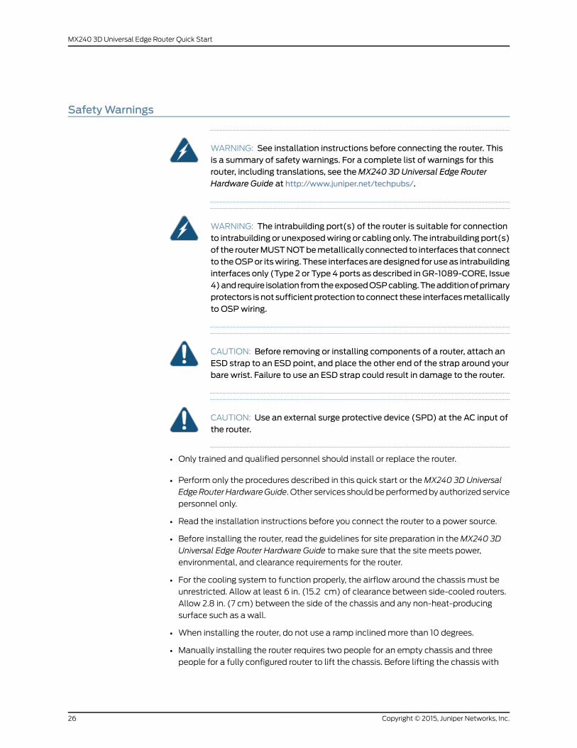
SafetyWarnings
WARNING: See installation instructions before connecting the router. Thisis a summary of safety warnings. For a complete list of warnings for thisrouter, including translations, see theMX240 3D Universal Edge RouterHardware Guide at http://www.juniper.net/techpubs/.
WARNING: The intrabuilding port(s) of the router is suitable for connectionto intrabuilding or unexposedwiring or cabling only. The intrabuilding port(s)of the routerMUSTNOTbemetallically connected to interfaces that connectto theOSPor itswiring. These interfacesaredesigned for useas intrabuildinginterfaces only (Type 2 or Type 4 ports as described in GR-1089-CORE, Issue4)andrequire isolation fromtheexposedOSPcabling.Theadditionofprimaryprotectors is not sufficientprotection toconnect these interfacesmetallicallyto OSPwiring.
CAUTION: Before removing or installing components of a router, attach anESD strap to an ESD point, and place the other end of the strap around yourbare wrist. Failure to use an ESD strap could result in damage to the router.
CAUTION: Use an external surge protective device (SPD) at the AC input ofthe router.
• Only trained and qualified personnel should install or replace the router.
• Perform only the procedures described in this quick start or theMX240 3D Universal
EdgeRouterHardwareGuide. Other services shouldbeperformedbyauthorized service
personnel only.
• Read the installation instructions before you connect the router to a power source.
• Before installing the router, read the guidelines for site preparation in theMX240 3D
Universal Edge Router Hardware Guide to make sure that the site meets power,
environmental, and clearance requirements for the router.
• For the cooling system to function properly, the airflow around the chassis must be
unrestricted. Allow at least 6 in. (15.2 cm) of clearance between side-cooled routers.
Allow 2.8 in. (7 cm) between the side of the chassis and any non-heat-producing
surface such as a wall.
• When installing the router, do not use a ramp inclinedmore than 10 degrees.
• Manually installing the router requires two people for an empty chassis and three
people for a fully configured router to lift the chassis. Before lifting the chassis with
Copyright © 2015, Juniper Networks, Inc.26
MX240 3D Universal Edge Router Quick Start
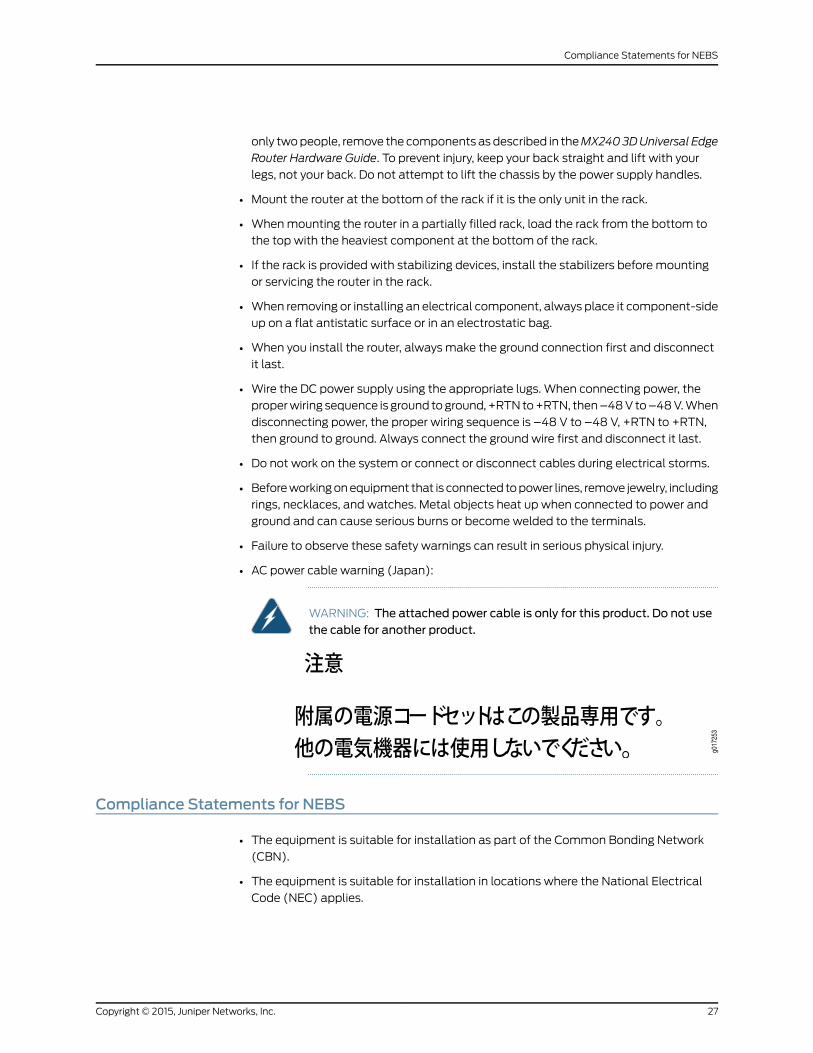
only twopeople, remove the components asdescribed in theMX2403DUniversal Edge
Router Hardware Guide. To prevent injury, keep your back straight and lift with your
legs, not your back. Do not attempt to lift the chassis by the power supply handles.
• Mount the router at the bottom of the rack if it is the only unit in the rack.
• Whenmounting the router in a partially filled rack, load the rack from the bottom to
the top with the heaviest component at the bottom of the rack.
• If the rack is provided with stabilizing devices, install the stabilizers before mounting
or servicing the router in the rack.
• When removing or installing an electrical component, always place it component-side
up on a flat antistatic surface or in an electrostatic bag.
• When you install the router, always make the ground connection first and disconnect
it last.
• Wire the DC power supply using the appropriate lugs. When connecting power, the
properwiring sequence is ground toground,+RTNto+RTN, then–48V to–48V.When
disconnecting power, the proper wiring sequence is –48 V to –48 V, +RTN to +RTN,
then ground to ground. Always connect the ground wire first and disconnect it last.
• Do not work on the system or connect or disconnect cables during electrical storms.
• Beforeworkingonequipment that is connected topower lines, remove jewelry, including
rings, necklaces, and watches. Metal objects heat up when connected to power and
ground and can cause serious burns or becomewelded to the terminals.
• Failure to observe these safety warnings can result in serious physical injury.
• AC power cable warning (Japan):
WARNING: The attached power cable is only for this product. Do not usethe cable for another product.
Compliance Statements for NEBS
• The equipment is suitable for installation as part of the Common Bonding Network
(CBN).
• The equipment is suitable for installation in locations where the National Electrical
Code (NEC) applies.
27Copyright © 2015, Juniper Networks, Inc.
Compliance Statements for NEBS

• The battery return connection is to be treated as an isolated DC return (i.e. DC-I), as
defined in GR-1089-CORE.
• For Juniper systemswith ACpower supplies, an external surge protective device (SPD)
must be used at the AC power source.
Compliance Statements for EMC Requirements
• Canada on page 28
• European Community on page 28
• Israel on page 28
• Japan on page 28
• United States on page 29
Canada
This Class A digital apparatus complies with Canadian ICES-003.
Cet appareil numérique de la classe A est conforme à la norme NMB-003 du Canada.
European Community
This is a Class A product. In a domestic environment this product may cause radio
interference in which case the user may be required to take adequate measures.
Israel
Translation from Hebrew—Warning: This product is Class A. In residential environments,
theproductmaycause radio interference, and in suchasituation, theusermaybe required
to take adequate measures.
Japan
Translation from Japanese—This is a Class A product. In a domestic environment this
product may cause radio interference in which case the user may be required to take
adequate measures. VCCI-A
Copyright © 2015, Juniper Networks, Inc.28
MX240 3D Universal Edge Router Quick Start

United States
Thehardware equipment has been tested and found to complywith the limits for aClass
Adigital device, pursuant toPart 15 of the FCCRules. These limits are designed toprovide
reasonable protection against harmful interference when the equipment is operated in
a commercial environment. This equipment generates, uses, and can radiate radio
frequencyenergyand, if not installedandused inaccordancewith the instructionmanual,
may cause harmful interference to radio communications. Operation of this equipment
in a residential area is likely to cause harmful interference in which case the user will be
required to correct the interference at his own expense.
29Copyright © 2015, Juniper Networks, Inc.
Compliance Statements for EMC Requirements
Junos Documentation and Release Notes
For a list of related Junos documentation, see
http://www.juniper.net/techpubs/software/junos/.
If the information in the latest release notes differs from the information in the
documentation, follow the Junos Release Notes.
To obtain the most current version of all Juniper Networks®technical documentation,
see the product documentation page on the Juniper Networks website at
http://www.juniper.net/techpubs/.
Requesting Technical Support
Technical product support is available through the JuniperNetworksTechnicalAssistance
Center (JTAC). If you are a customer with an active J-Care or JNASC support contract,
or are covered under warranty, and need postsales technical support, you can access
our tools and resources online or open a case with JTAC.
• JTAC policies—For a complete understanding of our JTAC procedures and policies,
review the JTAC User Guide located at
http://www.juniper.net/us/en/local/pdf/resource-guides/7100059-en.pdf.
• Product warranties—For product warranty information, visit
http://www.juniper.net/support/warranty/.
• JTAC Hours of Operation —The JTAC centers have resources available 24 hours a day,
7 days a week, 365 days a year.
Self-Help Online Tools and Resources
For quick and easy problem resolution, Juniper Networks has designed an online
self-service portal called the Customer Support Center (CSC) that provides youwith the
following features:
• Find CSC offerings: http://www.juniper.net/customers/support/
• Find product documentation: http://www.juniper.net/techpubs/
• Find solutions and answer questions using our Knowledge Base: http://kb.juniper.net/
• Download the latest versions of software and review release notes:
http://www.juniper.net/customers/csc/software/
• Search technical bulletins for relevant hardware and software notifications:
http://kb.juniper.net/InfoCenter/
• Join and participate in the Juniper Networks Community Forum:
http://www.juniper.net/company/communities/
• Open a case online in the CSC Case Management tool: http://www.juniper.net/cm/
Copyright © 2015, Juniper Networks, Inc.30
MX240 3D Universal Edge Router Quick Start
Toverify serviceentitlementbyproduct serial number, useourSerialNumberEntitlement
(SNE) Tool: https://tools.juniper.net/SerialNumberEntitlementSearch/
Opening a Casewith JTAC
You can open a case with JTAC on theWeb or by telephone.
• Use the Case Management tool in the CSC at http://www.juniper.net/cm/.
• Call 1-888-314-JTAC (1-888-314-5822 toll-free in the USA, Canada, and Mexico).
For international or direct-dial options in countries without toll-free numbers, visit us at
http://www.juniper.net/support/requesting-support.html
Revision History
January 2015—530-040793. Revision 1. Minor updates.
April 2011—Added high-capacity power information.
August 2010—530-036126. Revision 1. Revised initial configuration procedure.
December 2009—530-031141. Revision 1. Updated procedure for connecting DC power.
Updated information about FPCs and PICs. Updated lifting procedures.
February 2008—530-022141. Revision 1. Initial release.
Copyright © 2015, Juniper Networks, Inc. All rights reserved.
Juniper Networks, Junos, Steel-Belted Radius, NetScreen, and ScreenOS are registered trademarks of Juniper Networks, Inc. in the UnitedStates and other countries. The Juniper Networks Logo, the Junos logo, and JunosE are trademarks of Juniper Networks, Inc. All othertrademarks, service marks, registered trademarks, or registered service marks are the property of their respective owners.
Juniper Networks assumes no responsibility for any inaccuracies in this document. Juniper Networks reserves the right to change, modify,transfer, or otherwise revise this publication without notice.
31Copyright © 2015, Juniper Networks, Inc.
Requesting Technical Support