Embed Size (px)
Citation preview
MX100033DUniversal EdgeRouterQuick
Start
September 2017Part Number: 530-080552Revision 01
This document describes how to install the Juniper Networks®MX10003 3D Universal
Edge Router.
Contents MX10003 Quick Start Description . . . . . . . . . . . . . . . . . . . . . . . . . . . . . . . . . . . . . . . 3
Step 1: Prepare the Site for MX10003 Installation . . . . . . . . . . . . . . . . . . . . . . . . . . 4
Router Rack Requirements . . . . . . . . . . . . . . . . . . . . . . . . . . . . . . . . . . . . . . . . . 4
Router Clearance Requirements . . . . . . . . . . . . . . . . . . . . . . . . . . . . . . . . . . . . . 5
Router Cooling and Airflow Requirements . . . . . . . . . . . . . . . . . . . . . . . . . . . . . 5
Tools Required to Prepare the MX10003 Router for Installation . . . . . . . . . . . 6
Step 2: Install the MX10003 Chassis in the Rack . . . . . . . . . . . . . . . . . . . . . . . . . . . 6
Step 3: Connect the Grounding Cable . . . . . . . . . . . . . . . . . . . . . . . . . . . . . . . . . . . . 9
Step 4: Connect External Devices and Cables . . . . . . . . . . . . . . . . . . . . . . . . . . . . . 10
Connecting the Router to a Network for Out-of-Band Management . . . . . . . . 11
Connecting the Router to a Console Device . . . . . . . . . . . . . . . . . . . . . . . . . . . 12
Connecting the Router to External Clocking and Timing Devices . . . . . . . . . . 13
Connecting 1-PPS and 10-MHz Timing Devices to the Router . . . . . . . . . 13
Connecting a Time-of-Day Device to the Router . . . . . . . . . . . . . . . . . . . 14
Connecting a BITS External Clocking Device to the Router . . . . . . . . . . . 14
Step 5: Connect Power Cables . . . . . . . . . . . . . . . . . . . . . . . . . . . . . . . . . . . . . . . . . 15
Connect Power to an AC Router . . . . . . . . . . . . . . . . . . . . . . . . . . . . . . . . . . . . 15
Connect Power to a DC Router . . . . . . . . . . . . . . . . . . . . . . . . . . . . . . . . . . . . . 17
Step 6: Install the Air Filter Unit . . . . . . . . . . . . . . . . . . . . . . . . . . . . . . . . . . . . . . . . 19
Step 7: Perform Initial Software Configuration . . . . . . . . . . . . . . . . . . . . . . . . . . . . 20
Enter Configuration Mode . . . . . . . . . . . . . . . . . . . . . . . . . . . . . . . . . . . . . . . . 20
Configure User Accounts and Passwords . . . . . . . . . . . . . . . . . . . . . . . . . . . . 20
Configure System Attributes . . . . . . . . . . . . . . . . . . . . . . . . . . . . . . . . . . . . . . . 21
Commit the Configuration . . . . . . . . . . . . . . . . . . . . . . . . . . . . . . . . . . . . . . . . 22
Safety Warnings . . . . . . . . . . . . . . . . . . . . . . . . . . . . . . . . . . . . . . . . . . . . . . . . . . . . 22
1Copyright © 2017, Juniper Networks, Inc.
Compliance Statements for NEBS . . . . . . . . . . . . . . . . . . . . . . . . . . . . . . . . . . . . . 24
Compliance Statements for EMC Requirements . . . . . . . . . . . . . . . . . . . . . . . . . . 25
Canada . . . . . . . . . . . . . . . . . . . . . . . . . . . . . . . . . . . . . . . . . . . . . . . . . . . . . . . 25
European Community . . . . . . . . . . . . . . . . . . . . . . . . . . . . . . . . . . . . . . . . . . . . 25
Israel . . . . . . . . . . . . . . . . . . . . . . . . . . . . . . . . . . . . . . . . . . . . . . . . . . . . . . . . . 25
Japan . . . . . . . . . . . . . . . . . . . . . . . . . . . . . . . . . . . . . . . . . . . . . . . . . . . . . . . . . 25
United States . . . . . . . . . . . . . . . . . . . . . . . . . . . . . . . . . . . . . . . . . . . . . . . . . . . 25
Junos OS Documentation and Release Notes . . . . . . . . . . . . . . . . . . . . . . . . . . . . 26
Requesting Technical Support . . . . . . . . . . . . . . . . . . . . . . . . . . . . . . . . . . . . . . . . 26
Self-Help Online Tools and Resources . . . . . . . . . . . . . . . . . . . . . . . . . . . . . . 26
Opening a Case with JTAC . . . . . . . . . . . . . . . . . . . . . . . . . . . . . . . . . . . . . . . . 27
Revision History . . . . . . . . . . . . . . . . . . . . . . . . . . . . . . . . . . . . . . . . . . . . . . . . . . . . 27
Copyright © 2017, Juniper Networks, Inc.2
MX10003 3D Universal Edge Router Quick Start
MX10003Quick Start Description
ThisQuick Start contains information you need to install and configure the router quickly.
Forcomplete installation instructions, see theMX100033DUniversalEdgeRouterHardware
Guide at http://www.juniper.net/techpubs/.
WARNING: ThisQuickStart containsasummaryofsafetywarnings in “SafetyWarnings”onpage22.Foracomplete listofwarnings for this router, includingtranslations, see theMX10003 3D Universal Edge Router Hardware Guide athttp://www.juniper.net/techpubs/.
The JuniperNetworksMX100033DUniversal EdgeRouter is an Ethernet-optimized edge
router with 2.4-Tb capacity that provides both switching and carrier-class Ethernet
routing. The MX10003 router runs Junos operating system (Junos OS), enabling a wide
rangeofbusinessand residential applicationsandservices, includinghigh-speed transport
andvirtualprivatenetwork (VPN)services, next-generationbroadbandmultiplay services,
and high-volume Internet data center internetworking. Each router provides full duplex,
high-density Ethernet interfaces and high-capacity switching throughput and uses the
Junos Trio chipset for increased scalability of Layer 2 and Layer 3 packet forwarding,
buffering, and queuing.
The MX10003 router is compact and three rack units (3U) tall. Several routers can be
stacked in a single floor-to-ceiling rack for increased port density per unit of floor space.
The routerprovides twodedicated linecard slots forModularPortConcentrators (MPCs).
MPCs install into the line-card slots. The router supports two redundant Routing and
Control Board (RCB). The RCBs house the Routing Engines (see Figure 1 on page 4).
The router is powered by six dedicated AC or DC power modules. Cooling is handled by
four fan modules. The RCBs and MPCs install into the front of the chassis, whereas the
power and fanmodules install into the rear of the chassis.
The MX10003 line card has six built in QSFP+ optics ports and one slot for a MIC. For a
list of MPCs andMICs supported on theMX10003 router, seeMXSeries InterfaceModule
Reference.
3Copyright © 2017, Juniper Networks, Inc.
MX10003 Quick Start Description
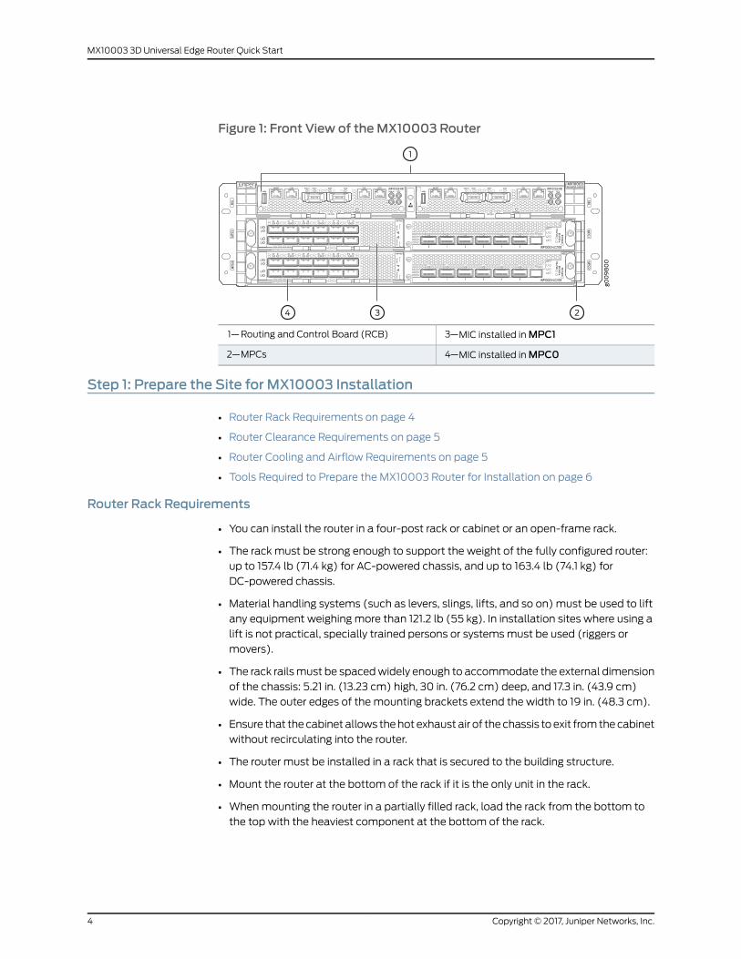
Figure 1: Front View of theMX10003 Router
3—1— MIC installed inMPC1Routing and Control Board (RCB)
4—2— MIC installed inMPC0MPCs
Step 1: Prepare the Site for MX10003 Installation
• Router Rack Requirements on page 4
• Router Clearance Requirements on page 5
• Router Cooling and Airflow Requirements on page 5
• Tools Required to Prepare the MX10003 Router for Installation on page 6
Router Rack Requirements
• You can install the router in a four-post rack or cabinet or an open-frame rack.
• The rack must be strong enough to support the weight of the fully configured router:
up to 157.4 lb (71.4 kg) for AC-powered chassis, and up to 163.4 lb (74.1 kg) for
DC-powered chassis.
• Material handling systems (such as levers, slings, lifts, and so on) must be used to lift
any equipment weighing more than 121.2 lb (55 kg). In installation sites where using a
lift is not practical, specially trained persons or systemsmust be used (riggers or
movers).
• The rack railsmust be spacedwidely enough to accommodate the external dimension
of the chassis: 5.21 in. (13.23 cm) high, 30 in. (76.2 cm) deep, and 17.3 in. (43.9 cm)
wide. The outer edges of the mounting brackets extend the width to 19 in. (48.3 cm).
• Ensure that the cabinet allows thehot exhaust air of the chassis to exit fromthecabinet
without recirculating into the router.
• The router must be installed in a rack that is secured to the building structure.
• Mount the router at the bottom of the rack if it is the only unit in the rack.
• Whenmounting the router in a partially filled rack, load the rack from the bottom to
the top with the heaviest component at the bottom of the rack.
Copyright © 2017, Juniper Networks, Inc.4
MX10003 3D Universal Edge Router Quick Start
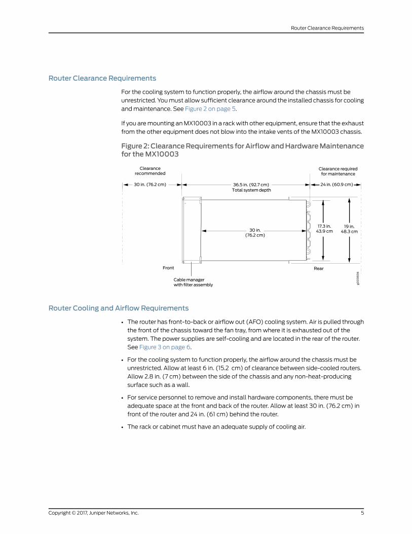
Router Clearance Requirements
For the cooling system to function properly, the airflow around the chassis must be
unrestricted. Youmust allow sufficient clearance around the installed chassis for cooling
andmaintenance. See Figure 2 on page 5.
If you aremounting anMX10003 in a rackwith other equipment, ensure that the exhaust
from the other equipment does not blow into the intake vents of the MX10003 chassis.
Figure2:ClearanceRequirements forAirflowandHardwareMaintenancefor theMX10003
Router Cooling and Airflow Requirements
• The router has front-to-back or airflow out (AFO) cooling system. Air is pulled through
the front of the chassis toward the fan tray, fromwhere it is exhausted out of the
system. The power supplies are self-cooling and are located in the rear of the router.
See Figure 3 on page 6.
• For the cooling system to function properly, the airflow around the chassis must be
unrestricted. Allow at least 6 in. (15.2 cm) of clearance between side-cooled routers.
Allow 2.8 in. (7 cm) between the side of the chassis and any non-heat-producing
surface such as a wall.
• For service personnel to remove and install hardware components, there must be
adequate space at the front and back of the router. Allow at least 30 in. (76.2 cm) in
front of the router and 24 in. (61 cm) behind the router.
• The rack or cabinet must have an adequate supply of cooling air.
5Copyright © 2017, Juniper Networks, Inc.
Router Clearance Requirements
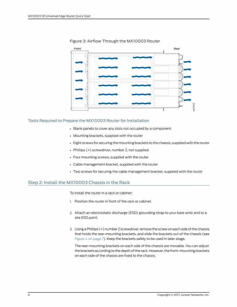
Figure 3: Airflow Through theMX10003 Router
Tools Required to Prepare theMX10003 Router for Installation
• Blank panels to cover any slots not occupied by a component
• Mounting brackets, supplied with the router
• Eight screws for securing themountingbrackets to thechassis, suppliedwith the router
• Phillips (+) screwdriver, number 2, not supplied
• Four mounting screws, supplied with the router
• Cable management bracket, supplied with the router
• Two screws for securing the cable management bracket, supplied with the router
Step 2: Install theMX10003 Chassis in the Rack
To install the router in a rack or cabinet:
1. Position the router in front of the rack or cabinet.
2. Attach an electrostatic discharge (ESD) grounding strap to your bare wrist and to a
site ESD point.
3. UsingaPhillips (+)number2 screwdriver, remove thescrewoneachsideof thechassis
that holds the rear-mounting brackets, and slide the brackets out of the chassis (see
Figure 4 on page 7). Keep the brackets safely to be used in later stage.
The rear-mounting brackets on each side of the chassis are movable. You can adjust
thebracketsaccording to thedepthof the rack.However, the front-mountingbrackets
on each side of the chassis are fixed to the chassis.
Copyright © 2017, Juniper Networks, Inc.6
MX10003 3D Universal Edge Router Quick Start
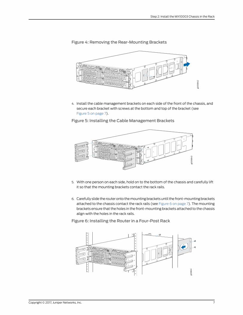
Figure 4: Removing the Rear-Mounting Brackets
4. Install the cable management brackets on each side of the front of the chassis, and
secure each bracket with screws at the bottom and top of the bracket (see
Figure 5 on page 7).
Figure 5: Installing the Cable Management Brackets
5. With one person on each side, hold on to the bottom of the chassis and carefully lift
it so that the mounting brackets contact the rack rails.
6. Carefully slide the router onto themountingbracketsuntil the front-mountingbrackets
attached to the chassis contact the rack rails (see Figure 6 on page 7). Themounting
brackets ensure that the holes in the front-mounting brackets attached to the chassis
align with the holes in the rack rails.
Figure 6: Installing the Router in a Four-Post Rack
g009
844
7Copyright © 2017, Juniper Networks, Inc.
Step 2: Install the MX10003 Chassis in the Rack
7. Install mounting screws into each of the open front-mounting holes aligned with the
rack, starting from the bottom, and secure them tightly.
8. Onthe rearof thechassis, slide the rear-mountingbracketsoneither sideof thechassis
until the rear-mounting brackets contact the rack rails.
9. Install mounting screws into each of the open rear-mounting holes aligned with the
rack, starting from the bottom, and secure them tightly.
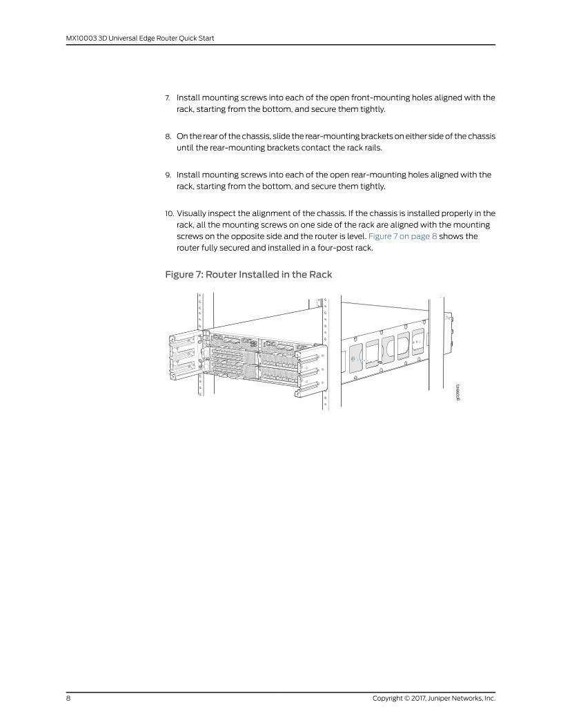
10. Visually inspect the alignment of the chassis. If the chassis is installed properly in the
rack, all the mounting screws on one side of the rack are aligned with the mounting
screws on the opposite side and the router is level. Figure 7 on page 8 shows the
router fully secured and installed in a four-post rack.
Figure 7: Router Installed in the Rack
g009
845
Copyright © 2017, Juniper Networks, Inc.8
MX10003 3D Universal Edge Router Quick Start
Step 3: Connect the Grounding Cable
Tomeet safety and electromagnetic interference (EMI) requirements and to ensure
proper operation, the router must be adequately grounded before power is connected.
A protective earthing terminal bracket is required for connecting the chassis to earth
ground. This two-holedbracket attaches on the side of the chassis through themounting
rail and provides a protective earthing terminal for the switch. The grounding points are
in the form of studs sized for M5 Pan Head screws. The M5 Pan Head screws with
integrated washers are provided in the accessory kit. The grounding points are spaced
at 0.75-in. (19.1-mm) centers.
Youground the routerbyconnectingagroundingcable toearthgroundand thenattaching
it to the chassis grounding points by using twoM5 Pan Head screws. Youmust provide
the grounding cables (the cable lugs are supplied with the router).
NOTE: The grounding lug required is a Panduit LCD10-14B-L or equivalent(not provided). The grounding lug accommodates 14–10 AWG (2–5.3mm²)strandedwire. The grounding cable that you provide for the chassis must bethe same size or heavier than the input wire of each power supply. Minimumrecommendations are 14–10 AWG (2–5.3mm²) stranded wire, 60° Cwire,or as permitted by local code.
To ground the MX10003 router:
1. Verify that a licensed electrician has attached the cable lug provided with the router
to the grounding cable.
2. Attachanelectrostaticdischarge (ESD)groundingstrap toyourbarewrist, andconnect
the strap to an approved site ESD grounding point. See the instructions for your site.
3. Ensure that all grounding surfaces are clean and brought to a bright finish before
grounding connections are made.
4. Connect the grounding cable to a proper earth ground.
5. Detach the ESD grounding strap from the site ESD grounding point.
6. Attach an ESD grounding strap to your bare wrist and connect the strap to one of the
ESD points on the chassis.
7. Place the grounding cable lug over the grounding points on the side of the chassis
(see Figure 8 on page 10).
9Copyright © 2017, Juniper Networks, Inc.
Step 3: Connect the Grounding Cable
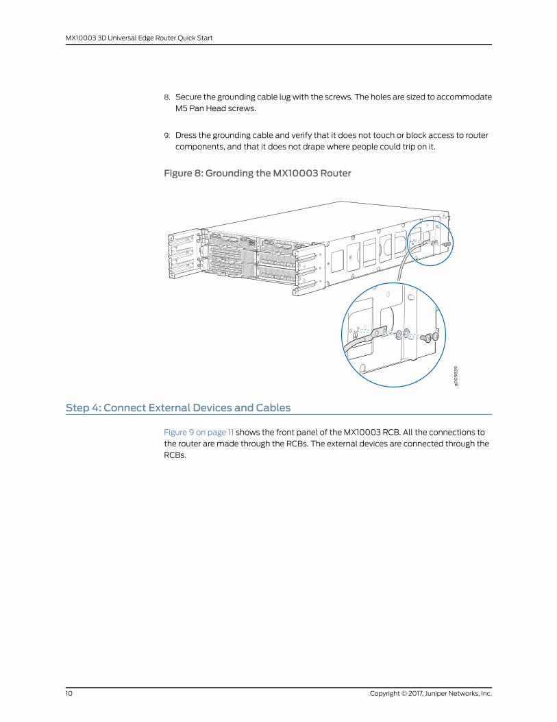
8. Secure the grounding cable lugwith the screws. The holes are sized to accommodate
M5 Pan Head screws.
9. Dress the grounding cable and verify that it does not touch or block access to router
components, and that it does not drape where people could trip on it.
Figure 8: Grounding theMX10003 Router
Step 4: Connect External Devices and Cables
Figure 9 on page 11 shows the front panel of the MX10003 RCB. All the connections to
the router are made through the RCBs. The external devices are connected through the
RCBs.
Copyright © 2017, Juniper Networks, Inc.10
MX10003 3D Universal Edge Router Quick Start
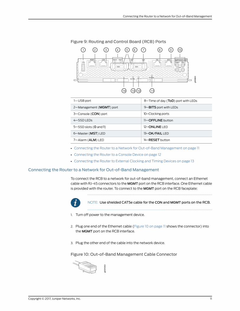
Figure 9: Routing and Control Board (RCB) Ports
g009
824
1 2 3 4 5 6 7 8 9 10
11121314
8—1— Time of day (ToD) port with LEDsUSB port
9—2— BITS port with LEDsManagement (MGMT) port
10—3— Clocking portsConsole (CON) port
11—4— OFFLINE buttonSSD LEDs
12—5— ONLINE LEDSSD slots (0 and 1)
13—6— OK/FAIL LEDMaster (MST) LED
14—7— RESET buttonAlarm (ALM) LED
• Connecting the Router to a Network for Out-of-Band Management on page 11
• Connecting the Router to a Console Device on page 12
• Connecting the Router to External Clocking and Timing Devices on page 13
Connecting the Router to a Network for Out-of-BandManagement
To connect the RCB to a network for out-of-bandmanagement, connect an Ethernet
cable with RJ-45 connectors to theMGMT port on the RCB interface. One Ethernet cable
is provided with the router. To connect to theMGMT port on the RCB faceplate:
NOTE: Use shielded CAT5e cable for the CON andMGMT ports on the RCB.
1. Turn off power to the management device.
2. Plug one end of the Ethernet cable (Figure 10 on page 11 shows the connector) into
theMGMT port on the RCB interface.
3. Plug the other end of the cable into the network device.
Figure 10: Out-of-BandManagement Cable Connector
11Copyright © 2017, Juniper Networks, Inc.
Connecting the Router to a Network for Out-of-Band Management
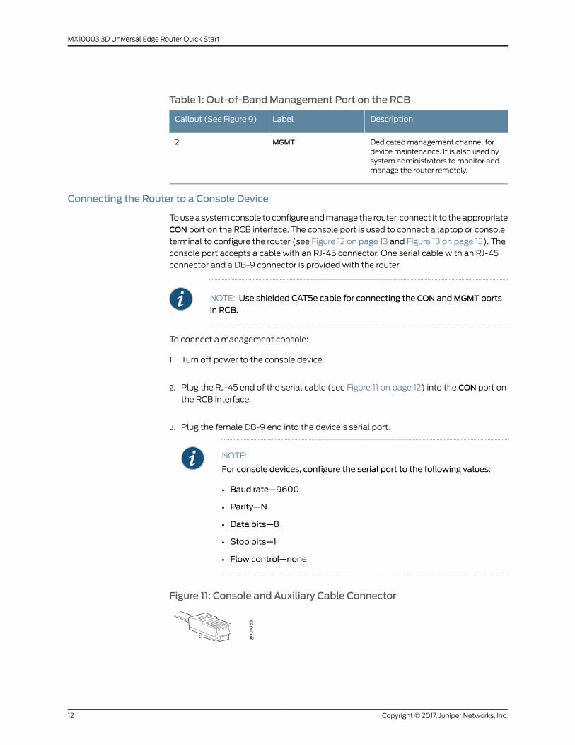
Table 1: Out-of-BandManagement Port on the RCB
DescriptionLabelCallout (See Figure 9)
Dedicatedmanagement channel fordevice maintenance. It is also used bysystem administrators to monitor andmanage the router remotely.
MGMT2
Connecting the Router to a Console Device
Touseasystemconsole toconfigureandmanage the router, connect it to theappropriate
CON port on the RCB interface. The console port is used to connect a laptop or console
terminal to configure the router (see Figure 12 on page 13 and Figure 13 on page 13). The
console port accepts a cable with an RJ-45 connector. One serial cable with an RJ-45
connector and a DB-9 connector is provided with the router.
NOTE: Use shielded CAT5e cable for connecting the CON andMGMT ports
in RCB.
To connect a management console:
1. Turn off power to the console device.
2. Plug the RJ-45 end of the serial cable (see Figure 11 on page 12) into the CON port on
the RCB interface.
3. Plug the female DB-9 end into the device's serial port.
NOTE:
For console devices, configure the serial port to the following values:
• Baud rate—9600
• Parity—N
• Data bits—8
• Stop bits—1
• Flow control—none
Figure 11: Console and Auxiliary Cable Connector
Copyright © 2017, Juniper Networks, Inc.12
MX10003 3D Universal Edge Router Quick Start

Figure 12: Connecting theMX10003 Router to aManagement ConsoleThrough a Console Server
g020
547
CON
To Consoleport Console server PC
Figure 13: Connecting theMX10003 Router Directly to aManagementConsole
Table 2: Console Port on the RCB
DescriptionLabelCallout (See Figure 9)
Connect a laptop or console terminalto configure the router.
CON3
Connecting the Router to External Clocking and Timing Devices
The router supportsexternal clocksynchronization forSynchronousEthernet, andexternal
inputs.
• Connecting 1-PPS and 10-MHz Timing Devices to the Router on page 13
• Connecting a Time-of-Day Device to the Router on page 14
• Connecting a BITS External Clocking Device to the Router on page 14
Connecting 1-PPS and 10-MHz Timing Devices to the Router
The router has four SubMiniature B (SMB) connectors that support 1-PPS and 10-MHz
timing devices.
NOTE: Ensure that a cable of 3mor less in length is used for the 10-MHz and1-PPS connectors.
To connect the SMB coaxial cable to the external clocking input port:
1. Connect one end of the SMB coaxial cable to either the 1-PPS SMB connector or the
10-MHz SMB connector on the router.
2. Connect theother endof theSMBcoaxial cable to the 10-MHzor 1-PPSsourcenetwork
equipment.
13Copyright © 2017, Juniper Networks, Inc.
Connecting the Router to External Clocking and Timing Devices

NOTE: Ensure that the 10-MHz or 1-PPS source network equipmentcontains Low Voltage Complementary Metal Oxide Semiconductor(LVCMOS) or is compatible with low-voltage (3.3 V) transistor-transistorlogic (LVTTL).
Table 3: Clocking Port on the RCB
DescriptionLabelCallout (See Figure 9)
GPS input and output ports.10MHz
PPS
10
Connecting a Time-of-Day Device to the Router
A time-of-day port labeled ToD on the front panel of the RCB enables you to connect
external timing devices.
To connect the router to a ToD external timing device:
1. Attachanelectrostaticdischarge (ESD)grounding traponyourbarewrist, andconnect
the strap to one of the ESD points on the chassis.
2. Plug one end of the RJ-45 cable into the ToD port on the front panel of the RCB.
3. Plug the other end of the RJ-45 cable into the ToD timing device.
4. Verify that the LEDs for the ToD port on the router are lit steadily green.
5. Configure theport.SeeConfiguringClockSynchronization InterfaceonMXSeriesRouters.
Table 4: Time-of-Day Port on the RCB
DescriptionLabelCallout (See Figure 9)
ToD RJ-45 port with LED.ToD8
Connecting a BITS External Clocking Device to the Router
The router has an external building-integrated timing supply (BITS) port labeled BITS
on the front panel of the RCB.
Copyright © 2017, Juniper Networks, Inc.14
MX10003 3D Universal Edge Router Quick Start
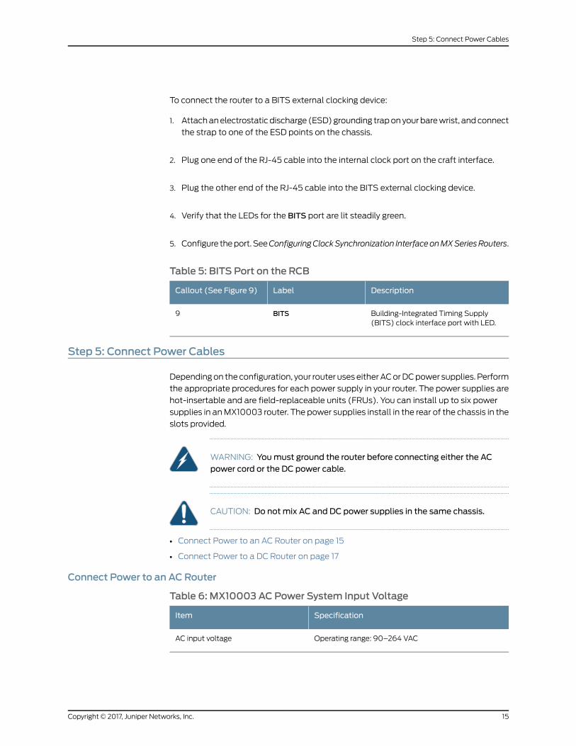
To connect the router to a BITS external clocking device:
1. Attachanelectrostaticdischarge (ESD)grounding traponyourbarewrist, andconnect
the strap to one of the ESD points on the chassis.
2. Plug one end of the RJ-45 cable into the internal clock port on the craft interface.
3. Plug the other end of the RJ-45 cable into the BITS external clocking device.
4. Verify that the LEDs for the BITS port are lit steadily green.
5. Configure theport.SeeConfiguringClockSynchronization InterfaceonMXSeriesRouters.
Table 5: BITS Port on the RCB
DescriptionLabelCallout (See Figure 9)
Building-Integrated Timing Supply(BITS) clock interface port with LED.
BITS9
Step 5: Connect Power Cables
Dependingon theconfiguration, your router useseitherACorDCpower supplies. Perform
the appropriate procedures for each power supply in your router. The power supplies are
hot-insertable and are field-replaceable units (FRUs). You can install up to six power
supplies in anMX10003 router. The power supplies install in the rear of the chassis in the
slots provided.
WARNING: Youmust ground the router before connecting either the ACpower cord or the DC power cable.
CAUTION: Do notmix AC and DC power supplies in the same chassis.
• Connect Power to an AC Router on page 15
• Connect Power to a DC Router on page 17
Connect Power to an AC Router
Table 6: MX10003 AC Power System Input Voltage
SpecificationItem
Operating range: 90–264 VACAC input voltage
15Copyright © 2017, Juniper Networks, Inc.
Step 5: Connect Power Cables
1. Locate power cords that have a plug appropriate for your geographical location. For
more information, see theMX10003 3D Universal Edge Router Hardware Guide at
http://www.juniper.net/techpubs/.
2. Attach an ESD grounding strap to your bare wrist and connect the strap to one of the
ESD points on the chassis.
3. Connect the power cord to the power supply.
4. Insert the power cord plug into an external AC power source receptacle.
NOTE: Each power supply must be connected to a dedicated AC powerfeed and a dedicated customer-site circuit breaker. We recommend thatyou use a dedicated customer-site circuit breaker rated for either15 A (110 VAC)minimum or 10 A (220 VAC)minimum, or as required bylocal code.
5. Fasten the cord retainer by lowering the clip over the cord and pushing the cord into
the adjustment nut of the cord retainer. Rotate the nut until it is tight against the base
of the cord (see Figure 14 on page 17).
6. Dress the power cord appropriately. Verify that the power cord does not block the air
exhaust and access to router components, or drape where people could trip on it.
7. Repeat Step 1 through Step 6 for the remaining power supply.
8. Switch the AC switch on each power supply to the on position (I) and observe the
status LEDoneachpower supply faceplate. If anACpower supply is correctly installed
and functioning normally, the status LED lights green steadily.
If the status LED indicates that the power supply is not functioning normally, repeat
the installation and cabling procedures.
Copyright © 2017, Juniper Networks, Inc.16
MX10003 3D Universal Edge Router Quick Start
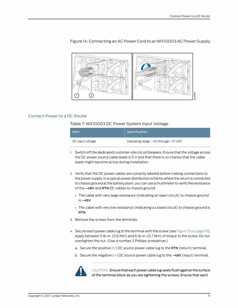
Figure 14:ConnectinganACPowerCord toanMX10003ACPowerSupply
Connect Power to a DC Router
Table 7: MX10003 DC Power System Input Voltage
SpecificationItem
Operating range: –40 through –72 VDCDC input voltage
1. Switchoff thededicatedcustomer-site circuit breakers. Ensure that the voltageacross
the DC power source cable leads is 0 V and that there is no chance that the cable
leads might become active during installation.
2. Verify that the DC power cables are correctly labeled before making connections to
thepower supply. In a typical powerdistribution schemewhere the return is connected
to chassis groundat thebattery plant, youcanuseamultimeter to verify the resistance
of the –48V and RTN DC cables to chassis ground:
• The cable with very large resistance (indicating an open circuit) to chassis ground
is –48V.
• The cable with very low resistance (indicating a closed circuit) to chassis ground is
RTN.
3. Remove the screws from the terminals.
4. Secure eachpower cable lug to the terminalwith the screw (see Figure 15 onpage 19).
Apply between 5 lb-in. (0.6 Nm) and 6 lb-in. (0.7 Nm) of torque to the screw. Do not
overtighten the nut. (Use a number 2 Phillips screwdriver.)
a. Secure the positive (+) DC source power cable lug to the RTN (return) terminal.
b. Secure the negative (–) DC source power cable lug to the –48V (input) terminal.
CAUTION: Ensure thateachpowercable lugseats flushagainst thesurfaceof the terminal block as you are tightening the screws. Ensure that each
17Copyright © 2017, Juniper Networks, Inc.
Connect Power to a DC Router
screw is properly threaded into the terminal. Applying installation torqueto the screwwhen improperly threadedmight result in damage to theterminal.
CAUTION: Themaximum torque rating of the terminal screws on the DCpower supply is 6 lb-in. (0.7 Nm). The terminal screwsmight be damagedif excessive torque isapplied.Useonlya torque-controlleddriver to tightenscrews on the DC power supply terminals. Use an appropriately-sizeddriver, with amaximum torque capacity of 6 lb-in. or less. Ensure that thedriver is undamaged and properly calibrated and that you have beentrained in itsuse.Youmightwant touseadriver that isdesigned topreventovertorque when the preset torque level is achieved.
5. Repeat Step 2 through Step 4 for the remaining power supplies.
6. Attachanelectrostaticdischarge (ESD)groundingstrap toyourbarewrist, andconnect
the strap to an approved site ESD grounding point. See the instructions for your site.
7. Connect each DC power cable to the appropriate external DC power source.
NOTE: For information about connecting to external DC power sources,see the instructions for your site.
8. Switch on the external circuit breakers to provide voltage to the DC power source
cable leads.
9. Switch on the circuit breakers on each power supply to the on position (|). Observe
the status LED on each power supply faceplate. If a DC power supply is correctly
installed and functioning normally, the status LED lights green steadily.
If the status LED indicates that the power supply is not functioning normally, repeat
the installation and cabling procedures.
Copyright © 2017, Juniper Networks, Inc.18
MX10003 3D Universal Edge Router Quick Start
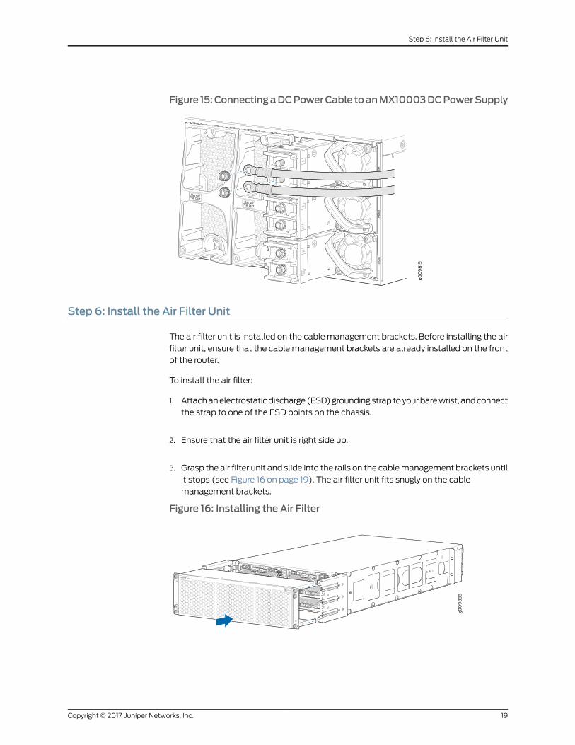
Figure 15:ConnectingaDCPowerCable toanMX10003DCPowerSupply
Step 6: Install the Air Filter Unit
The air filter unit is installed on the cablemanagement brackets. Before installing the air
filter unit, ensure that the cable management brackets are already installed on the front
of the router.
To install the air filter:
1. Attachanelectrostaticdischarge (ESD)groundingstrap toyourbarewrist, andconnect
the strap to one of the ESD points on the chassis.
2. Ensure that the air filter unit is right side up.
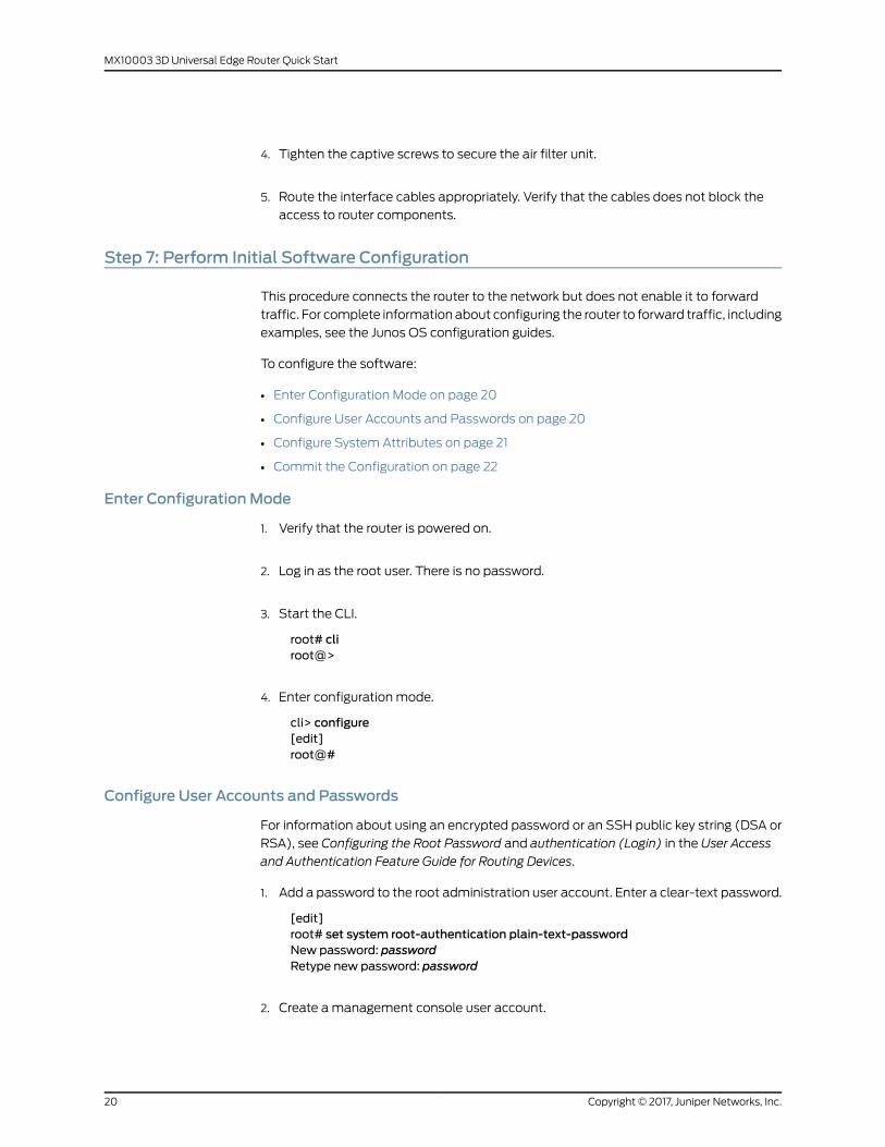
3. Grasp the air filter unit and slide into the rails on the cablemanagement brackets until
it stops (see Figure 16 on page 19). The air filter unit fits snugly on the cable
management brackets.
Figure 16: Installing the Air Filter
19Copyright © 2017, Juniper Networks, Inc.
Step 6: Install the Air Filter Unit
4. Tighten the captive screws to secure the air filter unit.
5. Route the interface cables appropriately. Verify that the cables does not block the
access to router components.
Step 7: Perform Initial Software Configuration
This procedure connects the router to the network but does not enable it to forward
traffic. For complete information about configuring the router to forward traffic, including
examples, see the Junos OS configuration guides.
To configure the software:
• Enter Configuration Mode on page 20
• Configure User Accounts and Passwords on page 20
• Configure System Attributes on page 21
• Commit the Configuration on page 22
Enter ConfigurationMode
1. Verify that the router is powered on.
2. Log in as the root user. There is no password.
3. Start the CLI.
root# cliroot@>
4. Enter configuration mode.
cli> configure[edit]root@#
Configure User Accounts and Passwords
For information about using an encrypted password or an SSH public key string (DSA or
RSA), see Configuring the Root Password and authentication (Login) in the User Access
and Authentication Feature Guide for Routing Devices.
1. Add a password to the root administration user account. Enter a clear-text password.
[edit]root# set system root-authentication plain-text-passwordNew password: passwordRetype new password: password
2. Create amanagement console user account.
Copyright © 2017, Juniper Networks, Inc.20
MX10003 3D Universal Edge Router Quick Start
[edit]root# set system login user user-name authentication plain-text-passwordNew Password: passwordRetype new password: password
3. Set the user account class to super-user.
[edit]root@# set system login user user-name class super-user
Configure SystemAttributes
1. Configure the name of the router. If the name includes spaces, enclose the name in
quotation marks (“ ”).
[edit]root@# set system host-name host-name
2. Configure the router’s domain name.
[edit]root@# set system domain-name domain-name
3. Configure the IP address and prefix length for the router’s Ethernet interface.
[edit]root@# set interfaces fxp0 unit 0 family inet address address/prefix-length
4. Configure the IP address of a backup router, which is used only while the routing
protocol is not running.
[edit]root@# set system backup-router address
5. Configure the IP address of a DNS server.
[edit]root@# set system name-server address
6. (Optional) Configure the static routes to remote subnets with access to the
management port. Access to the management port is limited to the local subnet. To
access the management port from a remote subnet, you need to add a static route
to that subnet within the routing table. For more information about static routes, see
the Junos OS Administration Library.
[edit]root@# set routing-options static route remote-subnet next-hop destination-IP retainno-readvertise
7. Configure the Telnet service at the [edit system services] hierarchy level.
[edit]root@# set system services telnet
21Copyright © 2017, Juniper Networks, Inc.
Configure System Attributes
Commit the Configuration
1. (Optional) Display the configuration to verify that it is correct.
[edit]root@# showsystem {host-name host-name;domain-name domain-name;backup-router address;root-authentication {authentication-method (password | public-key);
}name-server {address;
}}interfaces {fxp0 {unit 0 {family inet {address address/prefix-length;
}}
}}
2. Commit the configuration to activate it on the router.
[edit]root@# commit
3. (Optional) Configure additional properties by adding the necessary configuration
statements. Then commit the changes to activate them on the router.
[edit]root@host# commit
4. When you have finished configuring the router, exit configuration mode.
[edit]root@host# exitroot@host>
SafetyWarnings
WARNING: See installation instructions before connecting the router. Thisis a summary of safety warnings. For a complete list of warnings for thisrouter, including translations, see theMX10003 3D Universal Edge RouterHardware Guide at http://www.juniper.net/techpubs/.
Copyright © 2017, Juniper Networks, Inc.22
MX10003 3D Universal Edge Router Quick Start
WARNING: The intrabuilding port(s) of the router is suitable for connectionto intrabuilding or unexposedwiring or cabling only. The intrabuilding port(s)of the routerMUSTNOTbemetallically connected to interfaces that connectto theOSPor itswiring. These interfacesaredesigned for useas intrabuildinginterfaces only (Type 2 or Type 4 ports as described in GR-1089-CORE, Issue4)andrequire isolation fromtheexposedOSPcabling.Theadditionofprimaryprotectors is not sufficientprotection toconnect these interfacesmetallicallyto OSPwiring.
CAUTION: Before removing or installing components of a router, attach anESD strap to an ESD point, and place the other end of the strap around yourbare wrist. Failure to use an ESD strap could result in damage to the router.
CAUTION: Use an external surge protective device (SPD) at the AC input ofthe router.
• Only trained and qualified personnel should install or replace the router.
• Perform only the procedures described in this quick start or theMX10003 3D Universal
EdgeRouterHardwareGuideathttp://www.juniper.net/techpubs/. Other services should
be performed by authorized service personnel only.
• Read the installation instructions before you connect the router to a power source.
• Before installing the router, read the guidelines for site preparation in theMX10003 3D
Universal Edge Router Hardware Guide at http://www.juniper.net/techpubs/ to make
sure that the site meets power, environmental, and clearance requirements for the
router.
• For the cooling system to function properly, the airflow around the chassis must be
unrestricted. Allow at least 6 in. (15.2 cm) of clearance between side-cooled routers.
Allow 2.8 in. (7 cm) between the side of the chassis and any non-heat-producing
surface such as a wall.
• When installing the router, do not use a ramp inclinedmore than 10 degrees.
• Manually installing the router requires two people for an empty chassis and three
people for a fully configured router to lift the chassis. Before lifting the chassis with
only two people, remove the components as described in theMX10003 3D Universal
Edge Router Hardware Guide at http://www.juniper.net/techpubs/. To prevent injury,
keep your back straight and lift with your legs, not your back. Do not attempt to lift the
chassis by the power supply handles.
• Mount the router at the bottom of the rack if it is the only unit in the rack.
• Whenmounting the router in a partially filled rack, load the rack from the bottom to
the top with the heaviest component at the bottom of the rack.
23Copyright © 2017, Juniper Networks, Inc.
SafetyWarnings
• If the rack is provided with stabilizing devices, install the stabilizers before mounting
or servicing the router in the rack.
• When removing or installing an electrical component, always place it component-side
up on a flat antistatic surface or in an electrostatic bag.
• When you install the router, always make the ground connection first and disconnect
it last.
• Wire the DC power supply using the appropriate lugs. When connecting power, the
properwiring sequence is ground toground,+RTNto+RTN, then–48V to–48V.When
disconnecting power, the proper wiring sequence is –48 V to –48 V, +RTN to +RTN,
then ground to ground. Always connect the ground wire first and disconnect it last.
• Do not work on the system or connect or disconnect cables during electrical storms.
• Beforeworkingonequipment that is connected topower lines, remove jewelry, including
rings, necklaces, and watches. Metal objects heat up when connected to power and
ground and can cause serious burns or becomewelded to the terminals.
• Failure to observe these safety warnings can result in serious physical injury.
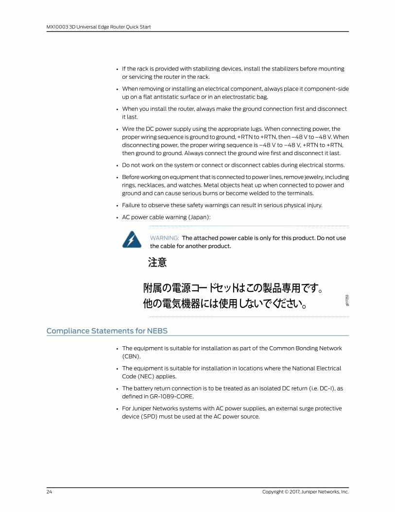
• AC power cable warning (Japan):
WARNING: The attached power cable is only for this product. Do not usethe cable for another product.
Compliance Statements for NEBS
• The equipment is suitable for installation as part of the Common Bonding Network
(CBN).
• The equipment is suitable for installation in locations where the National Electrical
Code (NEC) applies.
• The battery return connection is to be treated as an isolated DC return (i.e. DC-I), as
defined in GR-1089-CORE.
• For Juniper Networks systems with AC power supplies, an external surge protective
device (SPD)must be used at the AC power source.
Copyright © 2017, Juniper Networks, Inc.24
MX10003 3D Universal Edge Router Quick Start
Compliance Statements for EMC Requirements
• Canada on page 25
• European Community on page 25
• Israel on page 25
• Japan on page 25
• United States on page 25
Canada
CAN ICES-3 (A)/NMB-3(A)
European Community
This is a Class A product. In a domestic environment, this product might cause radio
interference in which case the user might be required to take adequate measures.
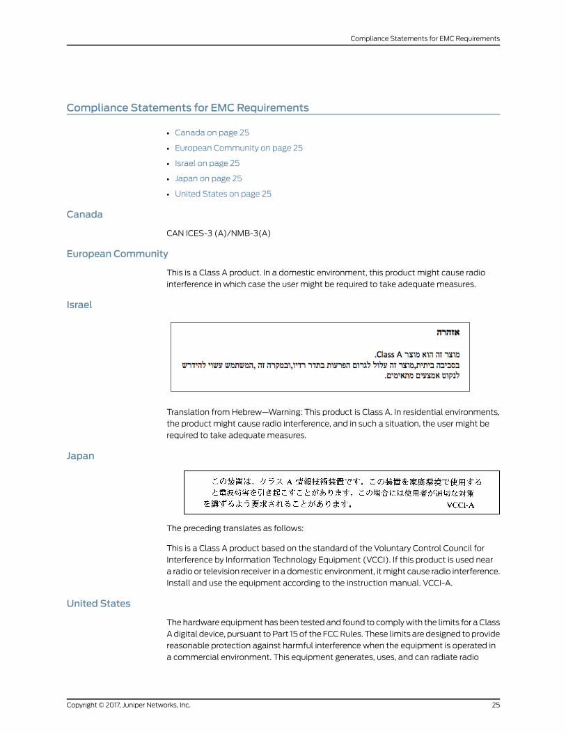
Israel
Translation from Hebrew—Warning: This product is Class A. In residential environments,
the product might cause radio interference, and in such a situation, the user might be
required to take adequate measures.
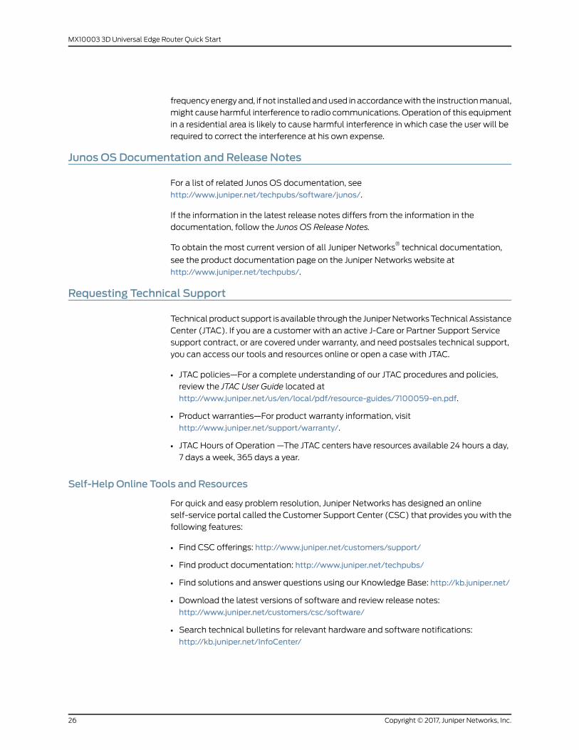
Japan
The preceding translates as follows:
This is a Class A product based on the standard of the Voluntary Control Council for
Interference by Information Technology Equipment (VCCI). If this product is used near
a radio or television receiver in a domestic environment, itmight cause radio interference.
Install and use the equipment according to the instruction manual. VCCI-A.
United States
Thehardware equipment has been tested and found to complywith the limits for aClass
Adigital device, pursuant toPart 15 of the FCCRules. These limits are designed toprovide
reasonable protection against harmful interference when the equipment is operated in
a commercial environment. This equipment generates, uses, and can radiate radio
25Copyright © 2017, Juniper Networks, Inc.
Compliance Statements for EMC Requirements
frequencyenergyand, if not installedandused inaccordancewith the instructionmanual,
might cause harmful interference to radio communications. Operation of this equipment
in a residential area is likely to cause harmful interference in which case the user will be
required to correct the interference at his own expense.
Junos OS Documentation and Release Notes
For a list of related Junos OS documentation, see
http://www.juniper.net/techpubs/software/junos/.
If the information in the latest release notes differs from the information in the
documentation, follow the Junos OS Release Notes.
To obtain the most current version of all Juniper Networks®technical documentation,
see the product documentation page on the Juniper Networks website at
http://www.juniper.net/techpubs/.
Requesting Technical Support
Technical product support is available through the JuniperNetworksTechnicalAssistance
Center (JTAC). If you are a customer with an active J-Care or Partner Support Service
support contract, or are covered under warranty, and need postsales technical support,
you can access our tools and resources online or open a case with JTAC.
• JTAC policies—For a complete understanding of our JTAC procedures and policies,
review the JTAC User Guide located at
http://www.juniper.net/us/en/local/pdf/resource-guides/7100059-en.pdf.
• Product warranties—For product warranty information, visit
http://www.juniper.net/support/warranty/.
• JTAC Hours of Operation —The JTAC centers have resources available 24 hours a day,
7 days a week, 365 days a year.
Self-Help Online Tools and Resources
For quick and easy problem resolution, Juniper Networks has designed an online
self-service portal called the Customer Support Center (CSC) that provides youwith the
following features:
• Find CSC offerings: http://www.juniper.net/customers/support/
• Find product documentation: http://www.juniper.net/techpubs/
• Find solutions and answer questions using our Knowledge Base: http://kb.juniper.net/
• Download the latest versions of software and review release notes:
http://www.juniper.net/customers/csc/software/
• Search technical bulletins for relevant hardware and software notifications:
http://kb.juniper.net/InfoCenter/
Copyright © 2017, Juniper Networks, Inc.26
MX10003 3D Universal Edge Router Quick Start
• Join and participate in the Juniper Networks Community Forum:
http://www.juniper.net/company/communities/
• Open a case online in the CSC Case Management tool: http://www.juniper.net/cm/
Toverify serviceentitlementbyproduct serial number, useourSerialNumberEntitlement
(SNE) Tool: https://entitlementsearch.juniper.net/entitlementsearch/
Opening a Casewith JTAC
You can open a case with JTAC on theWeb or by telephone.
• Use the Case Management tool in the CSC at http://www.juniper.net/cm/.
• Call 1-888-314-JTAC (1-888-314-5822 toll-free in the USA, Canada, and Mexico).
For international or direct-dial options in countries without toll-free numbers, visit us at
http://www.juniper.net/support/requesting-support.html
Revision History
September 2017—Revision 1. Initial release
Copyright © 2017 Juniper Networks, Inc. All rights reserved.
Juniper Networks, the Juniper Networks logo, Juniper, and Junos are registered trademarks of Juniper Networks, Inc. and/or its affiliates inthe United States and other countries. All other trademarks may be property of their respective owners.
Juniper Networks assumes no responsibility for any inaccuracies in this document. Juniper Networks reserves the right to change, modify,transfer, or otherwise revise this publication without notice.
27Copyright © 2017, Juniper Networks, Inc.
Requesting Technical Support