Embed Size (px)
Citation preview
OL-14435-01
C H A P T E R11
Mobile Access Router, Universal Bridge Client, and Cisco Unified Wireless3200 Series Mobile Access Router OverviewThe Cisco 3200 Series Mobile Access Router (MAR) is a compact, high-performance network access solution that offers seamless mobility and interoperability across multiple wireless networks. Its size makes it ideal for use in vehicles in defense, public safety, homeland security, and transportation. It delivers seamless communications mobility across multiple radio, cellular, satellite, and WLAN networks and can communicate mission-critical voice, video, and data across peer-to-peer, hierarchical, or meshed networks.
The Cisco 3200 router can be used to create a mobile network where devices such as PCs, surveillance cameras, digital video recorders, printers, PDAs, and scanners can all be backhauled to the home network through a wireless connection on the 3200, such as cellular or WLAN-based.
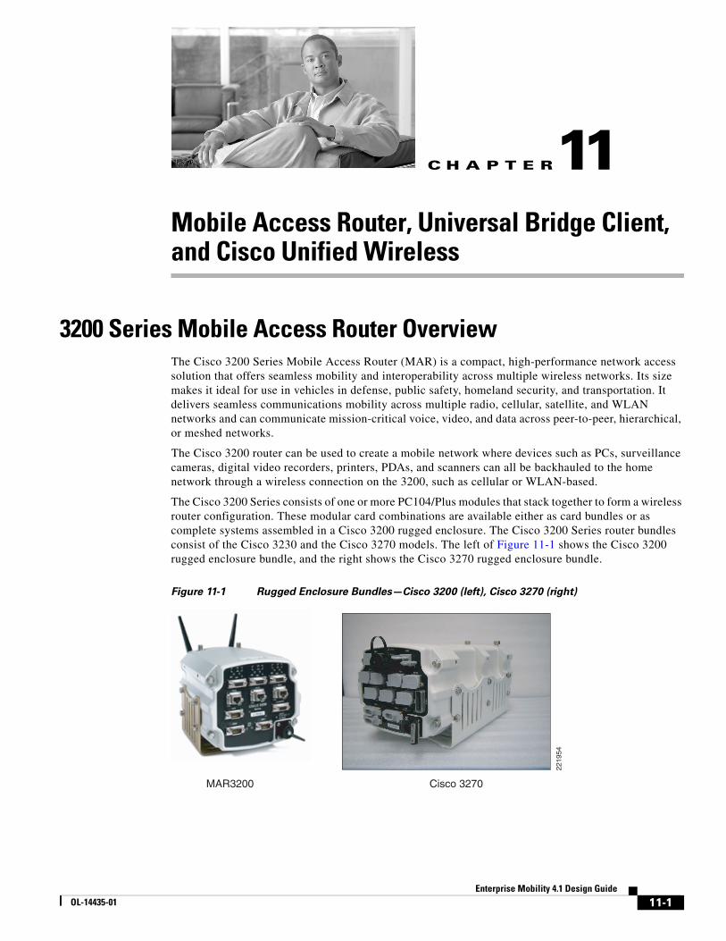
The Cisco 3200 Series consists of one or more PC104/Plus modules that stack together to form a wireless router configuration. These modular card combinations are available either as card bundles or as complete systems assembled in a Cisco 3200 rugged enclosure. The Cisco 3200 Series router bundles consist of the Cisco 3230 and the Cisco 3270 models. The left of Figure 11-1 shows the Cisco 3200 rugged enclosure bundle, and the right shows the Cisco 3270 rugged enclosure bundle.
Figure 11-1 Rugged Enclosure Bundles—Cisco 3200 (left), Cisco 3270 (right)
MAR3200 Cisco 3270
2219
54
11-1Enterprise Mobility 4.1 Design Guide
Chapter 11 Mobile Access Router, Universal Bridge Client, and Cisco Unified Wireless Cisco 3200 Series and Wireless Network Access
The Cisco Rugged Enclosure Option for the 3200 Series is designed for in-vehicle use, addressing the specific mobility needs of the public safety, transportation, defense, and homeland security markets. The Rugged Enclosure Option is completely sealed and is designed to withstand harsh environments, including large variations in temperature and altitude, intense shock/vibration, and exposure to dampness, moisture, or dust.
For more information and further details of the rugged enclosure, see the 3200 Rugged Enclosure data sheet at the following URL: http://www.cisco.com/en/US/products/hw/routers/ps272/products_data_sheet0900aecd8028e3a7.html
For more information on Cisco 3200 card bundles, see the Cisco 3200 Wireless and Mobile Routers data sheet at the following URL: http://www.cisco.com/en/US/products/hw/routers/ps272/products_data_sheet0900aecd800fe973.html
Cisco 3200 Series and Wireless Network AccessWith such a vast array of wireless options and connectivity modes, the Cisco 3200 MAR can deliver always on IP connectivity for networks in motion. These routers are intended to be mounted in vehicles. They support Cisco IOS Mobile Networks, and provide the ability to hide the address change that potentially occurs when roaming between Layer 3 subnets from the local IP nodes. This enables IP hosts on a mobile network to connect transparently to the network while a router is in motion.
For example, a bus equipped with the 3200 MAR is able to drive around a city while passengers on board the bus stay connected to the Internet. The client computers do not need any specialized software to maintain the connections. This transparent communication is accomplished by mobile IP devices that tunnel packets to the mobile access router, and is discussed further in this chapter.
Release 4.1 of the Cisco Unified Wireless Network has added support for workgroup bridge (WGB) functionality. Before this feature enhancement, a 3200 MAR would need to use Universal Work Group Bridge (UWGB) mode to connect to a Cisco Unified Wireless network.
By use of WGB, a 3200 MAR can act as a WGB client to a Cisco Unified Wireless Network. Outside of supporting WGB connections to Cisco 802.11 Unified Wireless Networks, it can be used to connect to other WLAN solutions that support WGB. The UWGB of the mobile access router is not superseded by the WGB feature. In fact, it is very useful in environments where you need to connect the 3200 MAR to 802.11 wireless networks that do not support WGB mode. In these types of network connections, the 3200 MAR in UWGB mode is seen as a normal wireless client to the 802.11 wireless network.
Another wireless access method for the 3200 MAR is through use of its wired Fast Ethernet and serial interface connections. Such connections can be used to integrate cellular and satellite devices. These device type options are beyond the scope of this document; more information can be found at the following URL: http://www.cisco.com/en/US/products/hw/routers/ps272/prod_brochure0900aecd80374174.html
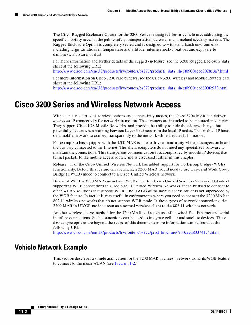
Vehicle Network ExampleThis section describes a simple application for the 3200 MAR in a mesh network using its WGB feature to connect to the mesh WLAN (see Figure 11-2.)
11-2Enterprise Mobility 4.1 Design Guide
OL-14435-01
Chapter 11 Mobile Access Router, Universal Bridge Client, and Cisco Unified Wireless Cisco 3200 Series and Wireless Network Access
Figure 11-2 Vehicle Network Example
Note the following:
• A Cisco 3200 Series router installed in a mobile unit allows the client devices in and around the vehicle to stay connected while the vehicle is roaming.
• Wireless Mobile Interface Cards (WMICs) in vehicle-mounted Cisco 3200 Series routers are configured as access points to provide connectivity for 802.11b/g and 4.9-GHz wireless clients.
• Ethernet interfaces are used to connect any in-vehicle wired clients, such as laptop, camera, or telematics devices, to the network.
• Another WMIC is configured as a WGB for connectivity to a mesh AP, allowing transparent association and authentication through a root device in the architecture as the vehicle moves about.
• Serial interfaces provide connectivity to wireless WAN modems that connect to cellular networks such as CDMA or GPRS. The wireless 802.11 connections are treated as preferred services because they offer the most bandwidth; however, when a WLAN connection is not available, cellular technology provides a backup link. Connection priority can be set by routing priority or by the priority for Mobile IP.
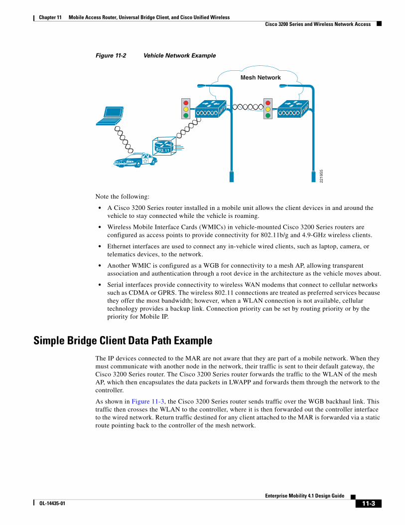
Simple Bridge Client Data Path ExampleThe IP devices connected to the MAR are not aware that they are part of a mobile network. When they must communicate with another node in the network, their traffic is sent to their default gateway, the Cisco 3200 Series router. The Cisco 3200 Series router forwards the traffic to the WLAN of the mesh AP, which then encapsulates the data packets in LWAPP and forwards them through the network to the controller.
As shown in Figure 11-3, the Cisco 3200 Series router sends traffic over the WGB backhaul link. This traffic then crosses the WLAN to the controller, where it is then forwarded out the controller interface to the wired network. Return traffic destined for any client attached to the MAR is forwarded via a static route pointing back to the controller of the mesh network.
Mesh Network
2219
55
802.11
11-3Enterprise Mobility 4.1 Design Guide
OL-14435-01
Chapter 11 Mobile Access Router, Universal Bridge Client, and Cisco Unified Wireless Cisco 3200 Series and Wireless Network Access
Figure 11-3 Simple Layer 2 Data Path Example
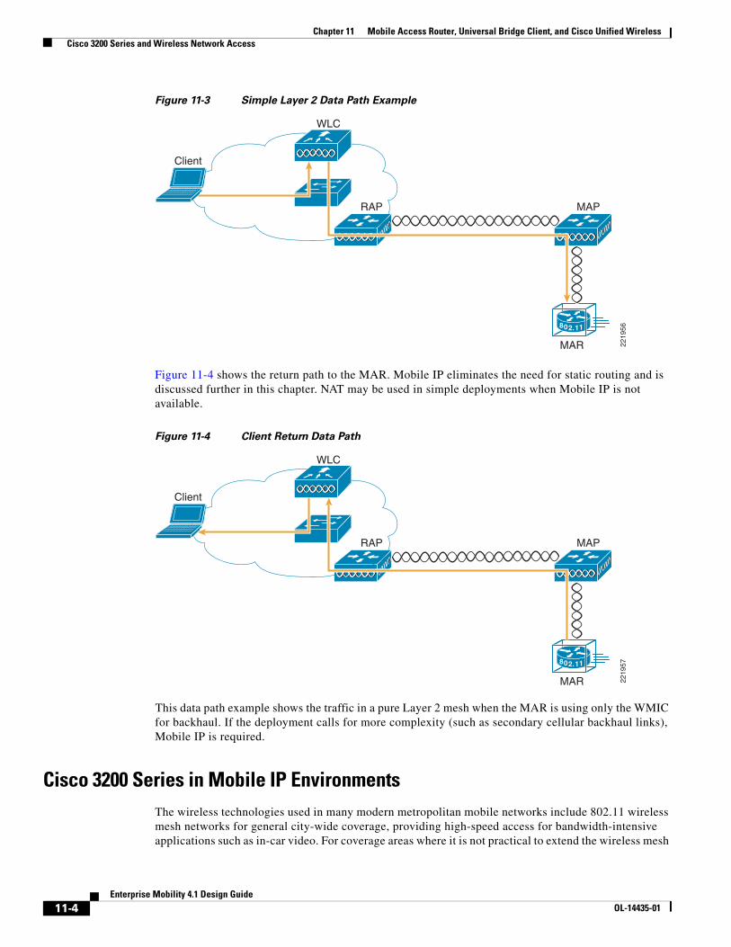
Figure 11-4 shows the return path to the MAR. Mobile IP eliminates the need for static routing and is discussed further in this chapter. NAT may be used in simple deployments when Mobile IP is not available.
Figure 11-4 Client Return Data Path
This data path example shows the traffic in a pure Layer 2 mesh when the MAR is using only the WMIC for backhaul. If the deployment calls for more complexity (such as secondary cellular backhaul links), Mobile IP is required.
Cisco 3200 Series in Mobile IP EnvironmentsThe wireless technologies used in many modern metropolitan mobile networks include 802.11 wireless mesh networks for general city-wide coverage, providing high-speed access for bandwidth-intensive applications such as in-car video. For coverage areas where it is not practical to extend the wireless mesh
2219
56802.11
MAPRAP
MAR
WLC
Client
2219
57802.11
MAPRAP
MAR
WLC
Client
11-4Enterprise Mobility 4.1 Design Guide
OL-14435-01
Chapter 11 Mobile Access Router, Universal Bridge Client, and Cisco Unified Wireless Cisco 3200 Series and Wireless Network Access
network, it can be supplemented by cellular services such as CDMA 1x RTT. By using this approach, cellular services can be used to fill gaps in connections and to provide backup wireless connectivity. This added backup interface requires Mobile IP to enable client roaming between the two separate networks.
In IP networks, routing is based on stationary IP addresses, similarly to how a postal letter is delivered to a fixed address on an envelope. A device on a network is reachable through IP routing by the IP address to which it is assigned on the network. However, when networks are in motion, problems occur when a device roams away from its home network and is no longer reachable using its existing IP route. This causes the active sessions of the device to be terminated.
Mobile IP offers a solution to these roaming problems by enabling users to keep the same IP address while traveling to a different network (which may even be operated by a different wireless operator), thus ensuring that a roaming client can continue communication without sessions or connection drops.
Because the mobility functions of Mobile IP are performed at the network layer rather than the physical or link layer, mobile devices such as the Cisco 3200 can span different types of wireless and wired networks while maintaining connections and ongoing applications. Any application that requires that the Session layer be maintained is a candidate for use on a Mobile IP-enabled network connection.
For a comprehensive overview of Mobile IP networking, see Chapter 12, “Cisco Unified Wireless and Mobile IP.”
WMIC Roaming Algorithm The following four basic triggers start the WMIC scanning for a better root bridge or access point:
1. Loss of eight consecutive beacons
2. Data rate shift
3. Maximum data retry count is exceeded (the default value is 64 on the WMIC)
4. A measured period of time of a drop in the signal strength threshold
Only #3 and #4 above are configurable via the packet retries command and mobile station period X threshold Y (in dBm); the remainder are hard-coded.
If a client starts scanning because of a loss of eight consecutive beacons, the following message is displayed on the console: “Too many missed beacons”. The WMIC in this case is acting as a universal bridge client much like any other wireless client in its behavior. An additional triggering mechanism, “mobile station,” is not periodic but does have two variables; period and threshold. If a mobile station is configured, the mobile station algorithm evaluates two variables (data rate shift and signal strength) and responds as follows:
• If the driver does a long-term downshift in the transmit rate for packets to the parent, the WMIC initiates a scan for a new parent (no more than once every configured period).
• If the signal strength (threshold) drops below a configurable level, the WMIC scans for a new parent (no more than once every configured period).
The data-rate shift can be displayed with the following command.
debug dot11 dot11Radio 0 trace print rates
However, this does not show the actual “data rate shift” algorithm in action, but only the changes in data rate. This determines the time period to scan depending on how much the data rate was decreased.
The period should be set depending on the application; default is 20 seconds. This delay period prevents the WMIC from constantly scanning for a better parent if, for example, the threshold is below the configured value.
11-5Enterprise Mobility 4.1 Design Guide
OL-14435-01
Chapter 11 Mobile Access Router, Universal Bridge Client, and Cisco Unified Wireless Basic Configuration Examples
The threshold sets the level at which the algorithm is triggered to scan for a better parent. This threshold should be set to noise+20dBm but not more than -70dBm (+70 because input for threshold is positive). The default is -70 dBm.
Basic Configuration ExamplesThis section provides a configuration example for the 3200 MAR. It can be used as a step-by-step process to configure the UWGB client using open authentication and WEP encryption. This section also covers other basic configuration steps such as VLAN creation, assignment, and DHCP.
Connecting to the Cisco 32XX
Step 1 Attach the console cable to both the serial port of your PC and the Mobile Access Router console port (DB9 female). Use a straight through DB9-to-DB9 cable.
Note You can also use the same console cable used to access the HA, with the addition of an RJ-45 to DB9 female adapter.
Configure IP Address, DHCP, VLAN on 3200 SeriesStep 2 Connect to and log into the mobile router. Create a loopback interface and assign an IP address.
Step 3 Create VLAN 2 in the VLAN database using the vlan database CLI command.
Step 4 Configure the VLAN 3 and VLAN 2 interfaces.
VLAN 3 is used for the 2.4 GHz WMIC2 (W2), which is acting as AP. VLAN 2 is used for the 4.9 GHz WMIC (W3). Configure FA2/0, FA2/1, and FA2/3 to be in VLAN 3, and FA 2/2 to be in VLAN 2.
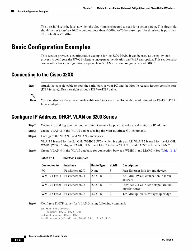
Step 5 Create VLAN 4 in the VLAN database for connection between WMIC 1 and MARC. (See Table 11-1.)
Step 6 Configure DHCP server for VLAN 3 using following command:
ip dhcp pool mypoolnetwork 10.40.10.0 /28
default-router 10.40.10.1ip dhcp excluded-address 10.40.10.1 10.40.10.3
Table 11-1 Interface Examples
Connected to Interface Radio Type VLAN Description
PC FastEthernet2/0 None 3 Fast Ethernet link for end device.
WMIC 1 (W1) FastEthernet2/1 2.4 GHz 4 2.4 GHz UWGB connection to mesh network
WMIC 2 (W2) FastEthernet2/3 2.4 GHz 3 Provides 2.4 GHz AP hotspot around mobile router
WMIC 3 (W3) FastEthernet2/2 4.9 GHz 2 4.9 GHz uplink as workgroup bridge
11-6Enterprise Mobility 4.1 Design Guide
OL-14435-01
Chapter 11 Mobile Access Router, Universal Bridge Client, and Cisco Unified Wireless Basic Configuration Examples
Step 7 Verify that the wired client on VLAN 3 is properly assigned a DHCP IP address in the 10.40.10.0/28 subnet.
WMIC Configurations
WMIC Work Group Bridge Configuration
WMICs can support the WGB client mode for 802.11 associated connections. This is the only operating mode that supports the distance command. It is also the suggested mode to configure for the MAR in a Cisco mesh environment because it overcomes limitations known to the UWGB client mode. For more information on UWGB including its limitations, see WMIC Universal Bridge Client Configuration, page 11-8.
There are the following three install modes for WGB:
• Automatic activates the bridge install and alignment mode, and specifies that the unit automatically determines the network role. If the unit is able to associate to another Cisco root device within 60 seconds, the unit assumes a non-root bridge role. The device can be configured into root bridge or non-root bridge modes to avoid the 60-second automatic detection phase.
• Root specifies that the device is operating as a root bridge and connects directly to the main Ethernet LAN network. In this mode, the unit accepts associations from other Cisco bridges and wireless client devices.
• Non-root specifies that the device is connecting to a remote LAN network, and that it must associate with a Cisco root device by using the wireless interface.
Follow these steps to configure the WMIC to determine is role automatically:
Step 1 Under the dot11 interface, enter the following command.
station-role {root [bridge | non-root workgroup-bridge install [automatic | root | non-root]}
The station-role command specifies that the role of the WMIC is chosen based on the device to which it is associated.
Step 2 Set the WMIC role.
• station-role root bridge—Specifies that the 3200 MAR WMIC operates as the root bridge device. This mode does not support wireless client associations.
• station-role workgroup-bridge—Specifies that the 3200 MAR WMIC operates in workgroup bridge mode. As a workgroup bridge, the device associates to an Aironet access point or bridge as a client and provides a wireless LAN connection for devices connected to its Ethernet port.
Step 3 Issue the mobile station command.
mobile station
Use this command to configure a non-root bridge or workgroup bridge as a mobile station. When this feature is enabled, the bridge scans for a new parent association whenever it encounters a poor received signal strength indicator (RSSI), excessive radio interference, or a high frame loss percentage. Using
11-7Enterprise Mobility 4.1 Design Guide
OL-14435-01
Chapter 11 Mobile Access Router, Universal Bridge Client, and Cisco Unified Wireless Security
these criteria, the WMIC searches for a new root association and roams to a new root device before it loses its current association. When the mobile station setting is disabled (the default setting) the WMIC does not search for a new association until it loses its current association.
WMIC Universal Bridge Client Configuration
The WMIC can be configured as a UWGB, as is discussed in the beginning of this section. UWGB mode enables support for the WMIC in a network 802.11 network environment that does not support WGB. For example, this may be a non-Cisco mesh network. The current limitation of using UWGB mode clients on a Cisco Unified Wireless Network is that you can only have one UWGB client per AP.
In this role, the WMIC has the following functionality:
• Associates to IOS and non-IOS access points.
• Interoperability—The UWGB can forward routing traffic using a non-Cisco root device as a universal client. The UWGB appears as a normal wireless client to the root device. As a root device, the WMIC supports Cisco Compatible Extension clients, with all Cisco Compatible Extension v3 features and many v4 features.
station-role workgroup-bridge universal (mac address)
Note You must use the MAC address of the associated VLAN to which the WMIC is bridged. As an example use the MAC address of VLAN one. To acquire the MAC address of VLAN one, console in to the MAR router card and issue the command show mac-address-table.
WMIC as an Access Point Configuration
The WMIC can be configured as a root access point. In this role, it accepts associations from wireless clients. This can be a useful configuration if you are planning to deploy a mobile hotspot. Issue the following command in the dot11 interface configuration to configure the WMIC as an access point:
station-role root access-point
This specifies that the WMIC functions as a root access point.
Security The security section of this chapter does not fully discuss in detail the underlying concepts behind the security features of the 3200 MAR; for more in depth information on these security mechanisms, see Chapter 4, “Cisco Unified Wireless Network Architecture —Base Security Features.”
Authentication TypesThis section describes the authentication types that you can configure on the WMIC. The authentication types are tied to the SSID that you configure on the WMIC. Before wireless devices can communicate, they must authenticate to each other using open, 802.1x/EAP-based, or shared-key authentication. For maximum security, wireless devices should also authenticate to your network using EAP authentication, which is an authentication type that relies on an authentication server on your network.
11-8Enterprise Mobility 4.1 Design Guide
OL-14435-01
Chapter 11 Mobile Access Router, Universal Bridge Client, and Cisco Unified Wireless Security
The WMIC uses four authentication mechanisms or types and can use more than one at the same time.
The following are the four authentication types that the WMIC can use:
• Open authentication to the WMIC
• Shared key authentication to the WMIC
• EAP authentication to the network
• MAC address authentication to the network
For more information on authentication mechanisms, see Chapter 4, “Cisco Unified Wireless Network Architecture —Base Security Features.”
Encryption and Key ManagementThe 3200 MAR WMIC supports Wired Equivalent Privacy (WEP), Wi-Fi Protected Access (WPA), and Cisco Centralized Key Management (CCKM) for encryption and key management. Further information on these security topics can be found in Chapter 4, “Cisco Unified Wireless Network Architecture —Base Security Features.”
Security ConfigurationThe default SSID on the WMIC is autoinstall, which is also configured as guest mode. In guest mode, the WMIC broadcasts this SSID in its beacon and allows client devices with no SSID to associate. Also by default, the authentication types assigned to autoinstall are open. This enables clients with no security settings whatsoever to connect to the 3200 MAR. To secure the MAR, this configuration default must be changed.
Assigning Authentication Types to an SSID
The commands following in this section cover the steps to configuring authentication types for SSIDs on a WMIC in root device mode. Each command is followed by a description of the command components and any optional configuration components.
• dot11 ssid ssid-string
This command defines an SSID. The SSID can consist of up to 32 alphanumeric characters. SSIDs are case sensitive.
• authentication open [mac-address list-name [alternate]] [[optional] eap list-name]
– (Optional) Sets the authentication type to open for this SSID. Open authentication allows any client device to authenticate and then attempt to communicate with the WMIC.
– (Optional) Sets the SSID authentication type to open with MAC address authentication. The access point forces all client devices to perform MAC address authentication before they are allowed to join the network. For list-name, specify the authentication method list. Additional information on method lists may be found at the following URL: http://www.cisco.com/en/US/docs/ios/12_2/security/configuration/guide/scfathen.html.
Use the alternate keyword to allow client devices to join the network using either MAC or EAP authentication; clients that successfully complete either authentication are allowed to join the network.
11-9Enterprise Mobility 4.1 Design Guide
OL-14435-01
Chapter 11 Mobile Access Router, Universal Bridge Client, and Cisco Unified Wireless Security
– (Optional) Sets the SSID authentication type to open with EAP authentication. The WMIC forces all other client devices to perform EAP authentication before they are allowed to join the network. For list-name, specify the authentication method list. Use the optional keyword to allow client devices using either open or EAP authentication to associate and become authenticated. This setting is used mainly by service providers that require special client accessibility.
Note A root device configured for EAP authentication forces all client devices that associate to perform EAP authentication. Client devices that do not use EAP cannot communicate with the root device.
• authentication shared
[mac-address list-name] [eap list-name]
– (Optional) Sets the authentication type for the SSID to shared key.
Note Because of shared key's security flaws, Cisco recommends that you avoid using it.
Note You can assign shared key authentication to only one SSID.
– (Optional) Sets the SSID authentication type to shared key with MAC address authentication. For list-name, specify the authentication method list.
– (Optional) Sets the SSID authentication type to shared key with EAP authentication. For list-name, specify the authentication method list.
• authentication network-eap list-name [mac-address list-name]
– (Optional) Sets the authentication type for the SSID to use EAP for authentication and key distribution.
– (Optional) Sets the SSID authentication type to Network-EAP with MAC address authentication. All client devices that associate to the access point are required to perform MAC address authentication. For list-name, specify the authentication method list.
• authentication key-management {[wpa] [cckm]} [optional]
– (Optional) Sets the key-management type for the SSID to WPA, CCKM, or both. If you use the optional keyword, client devices not configured for WPA or CCKM can use this SSID. If you do not use the optional keyword, only WPA or CCKM client devices are allowed to use the SSID. To enable CCKM for an SSID, you must also enable Network-EAP authentication. To enable WPA for an SSID, you must also enable Open authentication or Network-EAP, or both.
Note Only 802.11b and 802.11g radios support WPA and CCKM simultaneously.
Note Before you can enable CCKM or WPA, you must set the encryption mode to a cipher suite that includes TKIP/AES-CCMP. To enable both CCKM and WPA, you must set the encryption mode to a cipher suite that includes TKIP.
11-10Enterprise Mobility 4.1 Design Guide
OL-14435-01
Chapter 11 Mobile Access Router, Universal Bridge Client, and Cisco Unified Wireless Security
Note If you enable WPA for an SSID without a pre-shared key, the key management type is WPA. If you enable WPA with a pre-shared key, the key management type is WPA-PSK.
Note To support CCKM, your root device must interact with the WDS device on your network.
Configuring dot1x Credentials
The commands in this section cover the steps to configure dot1x credentials for use with EAP. Each command is followed by a description of the commands components and any optional configuration components.
1. eap profile profile-name-string
Creates the EAP profile.
2. dot1x credentials profile
Creates a dot1x credentials profile and enters the dot1x credentials configuration submode.
3. method [fast|gtc|leap|md5|mschapv2|tls]
Chooses an EAP authentication method for authentication purposes.
Note A device configured for EAP authentication forces all root devices that associate to perform EAP authentication. Root devices that do not use EAP cannot communicate with the device.
4. dot11 ssid ssid-string
5. authentication network-eap list-name
(Optional) Sets the authentication type for the SSID to use EAP for authentication and key distribution.
6. dot1x credentials profile
Creates a dot1x credentials profile and enters the dot1x credentials configuration submode.
7. dot1x eap profile profile-name-string
Specifies the EAP profile. This is the profile created in step 2 above.
8. authentication key-management {[wpa] [cckm]} [optional]
(Optional) Sets the key-management type for the SSID to WPA, CCKM, or both. If you use the optional keyword, client devices not configured for WPA or CCKM can use this SSID. If you do not use the optional keyword, only WPA or CCKM client devices are allowed to use the SSID. To enable CCKM for an SSID, you must also enable Network-EAP authentication. To enable WPA for an SSID, you must also enable Open authentication or Network-EAP or both.
Note Only 802.11b and 802.11g radios support WPA and CCKM simultaneously.
11-11Enterprise Mobility 4.1 Design Guide
OL-14435-01
Chapter 11 Mobile Access Router, Universal Bridge Client, and Cisco Unified Wireless Security
Note Before you can enable CCKM or WPA, you must set the encryption mode to a cipher suite that includes TKIP/AES-CCMP. To enable both CCKM and WPA, you must set the encryption mode to a cipher suite that includes TKIP.
Note If you enable WPA for an SSID without a pre-shared key, the key management type is WPA. If you enable WPA with a pre-shared key, the key management type is WPA-PSK.
Note To support CCKM, your root device must interact with the WDS device on your network.
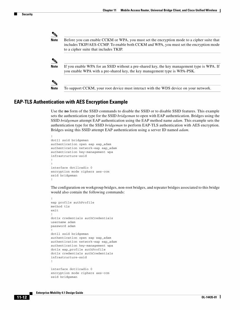
EAP-TLS Authentication with AES Encryption Example
Use the no form of the SSID commands to disable the SSID or to disable SSID features. This example sets the authentication type for the SSID bridgeman to open with EAP authentication. Bridges using the SSID bridgeman attempt EAP authentication using the EAP method name adam. This example sets the authentication type for the SSID bridgeman to perform EAP-TLS authentication with AES encryption. Bridges using this SSID attempt EAP authentication using a server ID named adam.
!dot11 ssid bridgemanauthentication open eap eap_adamauthentication network-eap eap_adamauthentication key-management wpainfrastructure-ssid!!interface dot11radio 0encryption mode ciphers aes-ccmssid bridgeman!
The configuration on workgroup bridges, non-root bridges, and repeater bridges associated to this bridge would also contain the following commands:
!eap profile authProfilemethod tlsexit!dot1x credentials authCredentialsusername adampassword adam!dot11 ssid bridgemanauthentication open eap eap_adamauthentication network-eap eap_adamauthentication key-management wpadot1x eap_profile authProfiledot1x credentials authCredentialsinfrastructure-ssid!
interface dot11radio 0encryption mode ciphers aes-ccmssid bridgeman
11-12Enterprise Mobility 4.1 Design Guide
OL-14435-01
Chapter 11 Mobile Access Router, Universal Bridge Client, and Cisco Unified Wireless Security
!!
This example shows the RADIUS/AAA configuration on the root side for EAP authentication.
!aaa new-modelaaa group server radius rad_eapserver 13.1.1.99 auth-port 1645 acct-port 1646!aaa authentication login eap_adam group rad_eapaaa session-id commonradius-server host 13.1.1.99 auth-port 1645 acct-port 1646 key 7 141B1309radius-server authorization permit missing Service-Typeip radius source-interface BVI1!
Configuring the Root Device Interaction with WDS
To support non-root bridges using CCKM, your root device must interact with the WDS device on your network, and your authentication server must be configured with a username and password for the root device. For detailed instructions on configuring WDS and CCKM on your wireless LAN, see Chapter 11 in the Cisco IOS Software Configuration Guide for Cisco Access Points at the following URL: http://www.cisco.com/en/US/docs/wireless/access_point/12.2_13_JA/configuration/guide/i12213sc.html.
On your root device, enter the following command in global configuration mode:
bridge(config)# wlccp ap username username password password
Note You must configure the same username and password pair when you set up the root device as a client on your authentication server.
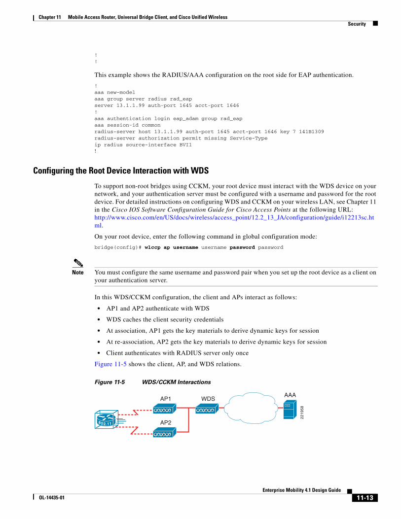
In this WDS/CCKM configuration, the client and APs interact as follows:
• AP1 and AP2 authenticate with WDS
• WDS caches the client security credentials
• At association, AP1 gets the key materials to derive dynamic keys for session
• At re-association, AP2 gets the key materials to derive dynamic keys for session
• Client authenticates with RADIUS server only once
Figure 11-5 shows the client, AP, and WDS relations.
Figure 11-5 WDS/CCKM Interactions
2219
58
802.11
AP1 WDSAAA
AP2
11-13Enterprise Mobility 4.1 Design Guide
OL-14435-01
Chapter 11 Mobile Access Router, Universal Bridge Client, and Cisco Unified Wireless Security
Configuring Additional WPA Settings
Use two optional settings to configure a pre-shared key on the bridge and adjust the frequency of group key updates.
Setting a Pre-Shared Key
To support WPA on a wireless LAN where 802.1x-based authentication is not available, you must configure a pre-shared key on the bridge. You can enter the pre-shared key as ASCII or hexadecimal characters. If you enter the key as ASCII characters, you enter between 8 and 63 characters, and the bridge expands the key using the process described in the Password-based Cryptography Standard (RFC2898). If you enter the key as hexadecimal characters, you must enter 64 hexadecimal characters. Keep in mind that WPA-PSK is susceptible to some known attack tools. However, note that the WPA-PSK authentication mechanism was intended to be used for consumer networks, not small-to-medium businesses or enterprise networks, and is not suggested to be used in an enterprise-class WGB or mesh environment.
Fortunately, off-line dictionary attacks are not very effective against WPA-PSK networks, because of the IEEE selection of the pbkdf2 algorithm for PSK hashing. A key generated from a passphrase of less than approximately 20 characters is likely to be vulnerable to a dictionary attack. If you intend to use WPA-PSK, it is recommended that you use only truly random keys.
Configuring Group Key Updates
In the last step in the WPA process, the root device distributes a group key to the authenticated non-root bridge. You can use the following optional settings to configure the root device to change and distribute the group key based on association and disassociation of non-root bridges:
• Membership termination—The root device generates and distributes a new group key when any authenticated non-root bridge disassociates from the root device. This feature keeps the group key private for associated bridges.
• Capability change—The root device generates and distributes a dynamic group key when the last non-key management non-root bridge disassociates, and it distributes the statically configured key when the first non-key management non-root bridge authenticates. In WPA migration mode, this feature significantly improves the security of key-management capable clients.
Beginning in privileged EXEC mode, follow these steps to configure a WPA pre-shared key and group key update options:
1. Enter SSID configuration mode for the SSID:
dot11 ssid ssid-string
2. Enter a pre-shared key for bridges using WPA that also use static WEP keys.
wpa-psk { hex | ascii } [ 0 | 7 ] encryption-key
Enter the key using either hexadecimal or ASCII characters. If you use hexadecimal, you must enter 64 hexadecimal characters to complete the 256-bit key. If you use ASCII, you must enter a minimum of 8 letters, numbers, or symbols, and the bridge expands the key for you. You can enter a maximum of 63 ASCII characters.
WPA and Pre-shared Key Configuration Example
The following example shows how to configure a pre-shared key for non-root bridges using WPA and static WEP, with group key update options:
11-14Enterprise Mobility 4.1 Design Guide
OL-14435-01
Chapter 11 Mobile Access Router, Universal Bridge Client, and Cisco Unified Wireless Cisco 3200 Series Product Details
!!dot11 ssid given-ssidwpa-psk ascii talboeitm65!!
Cisco 3200 Series Product Details
Cisco 3200 Series InterfacesAs mentioned in the previous section, the 3200 MAR Series router can be custom-designed with an assortment of PC104/Plus modules per your application needs. It is possible to design the routers for multiple Ethernet and serial interfaces as well as up to three WMIC cards. The router itself consists of stackable PC104/Plus modules referred to as cards. It can have up to the following card configurations:
• Two 2.4 GHz wireless WMICs
• One 4.9 GHz WMIC
• One Fast Ethernet Switch Mobile Interface Card (FESMIC)
• One Serial Mobile Interface Card
• One Mobile Access Router Card (MARC)
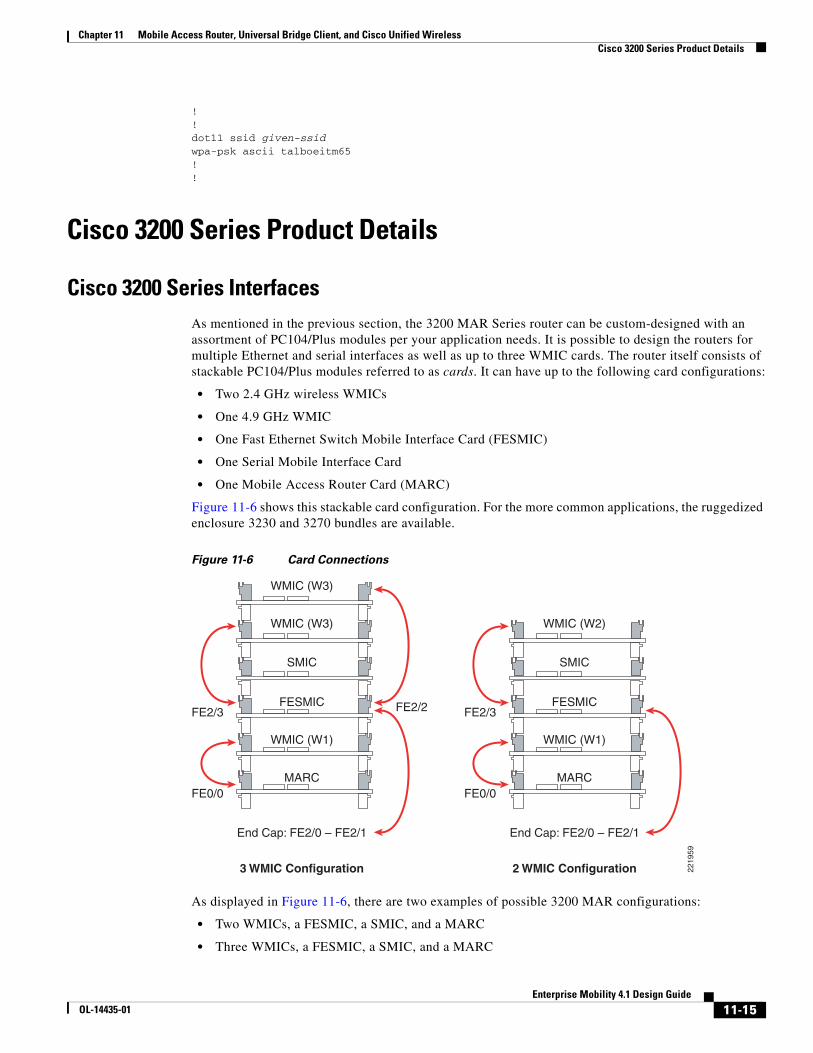
Figure 11-6 shows this stackable card configuration. For the more common applications, the ruggedized enclosure 3230 and 3270 bundles are available.
Figure 11-6 Card Connections
As displayed in Figure 11-6, there are two examples of possible 3200 MAR configurations:
• Two WMICs, a FESMIC, a SMIC, and a MARC
• Three WMICs, a FESMIC, a SMIC, and a MARC
2219
59
WMIC (W3)
FESMIC
SMIC
WMIC (W1)
MARC
End Cap: FE2/0 – FE2/1
FE2/3
FE0/0
FE2/2
End Cap: FE2/0 – FE2/1
3 WMIC Configuration 2 WMIC Configuration
WMIC (W3)
WMIC (W2)
FESMIC
SMIC
WMIC (W1)
MARC
FE2/3
FE0/0
11-15Enterprise Mobility 4.1 Design Guide
OL-14435-01
Chapter 11 Mobile Access Router, Universal Bridge Client, and Cisco Unified Wireless Cisco 3200 Series Product Details
For more information on 3200 MAR configuration options, see the following URL: http://www.cisco.com/en/US/products/hw/routers/ps272/products_data_sheet0900aecd800fe973.html.
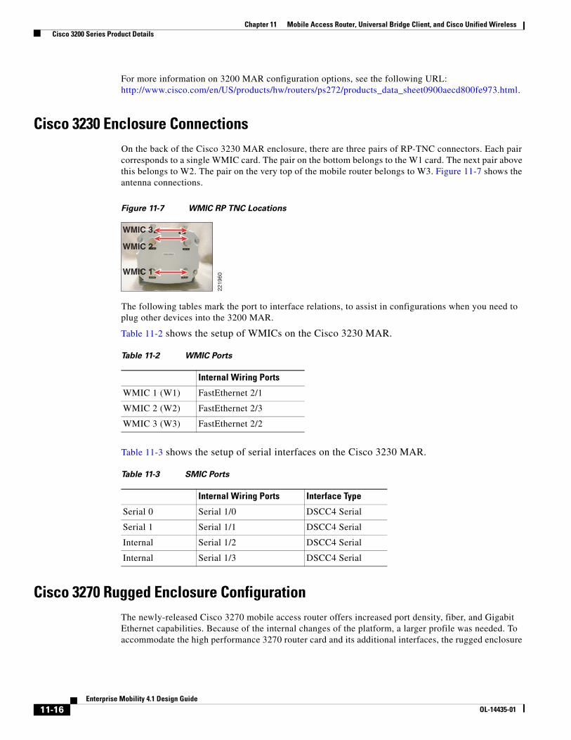
Cisco 3230 Enclosure ConnectionsOn the back of the Cisco 3230 MAR enclosure, there are three pairs of RP-TNC connectors. Each pair corresponds to a single WMIC card. The pair on the bottom belongs to the W1 card. The next pair above this belongs to W2. The pair on the very top of the mobile router belongs to W3. Figure 11-7 shows the antenna connections.
Figure 11-7 WMIC RP TNC Locations
The following tables mark the port to interface relations, to assist in configurations when you need to plug other devices into the 3200 MAR.
Table 11-2 shows the setup of WMICs on the Cisco 3230 MAR.
Table 11-3 shows the setup of serial interfaces on the Cisco 3230 MAR.
Cisco 3270 Rugged Enclosure ConfigurationThe newly-released Cisco 3270 mobile access router offers increased port density, fiber, and Gigabit Ethernet capabilities. Because of the internal changes of the platform, a larger profile was needed. To accommodate the high performance 3270 router card and its additional interfaces, the rugged enclosure
2219
60
WMIC 2
WMIC 1
WMIC 3
Table 11-2 WMIC Ports
Internal Wiring Ports
WMIC 1 (W1) FastEthernet 2/1
WMIC 2 (W2) FastEthernet 2/3
WMIC 3 (W3) FastEthernet 2/2
Table 11-3 SMIC Ports
Internal Wiring Ports Interface Type
Serial 0 Serial 1/0 DSCC4 Serial
Serial 1 Serial 1/1 DSCC4 Serial
Internal Serial 1/2 DSCC4 Serial
Internal Serial 1/3 DSCC4 Serial
11-16Enterprise Mobility 4.1 Design Guide
OL-14435-01
Chapter 11 Mobile Access Router, Universal Bridge Client, and Cisco Unified Wireless Cisco 3200 Series Product Details
for the 3270 is approximately double the size of the rugged enclosure used to house the 3230 bundles. This allows for greater expansion of PC104+ cards when compared to the maximum capacity of seven cards in the rugged enclosure for the Cisco 3230 bundles.
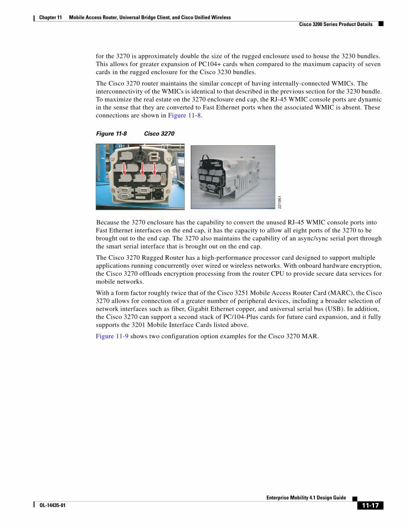
The Cisco 3270 router maintains the similar concept of having internally-connected WMICs. The interconnectivity of the WMICs is identical to that described in the previous section for the 3230 bundle. To maximize the real estate on the 3270 enclosure end cap, the RJ-45 WMIC console ports are dynamic in the sense that they are converted to Fast Ethernet ports when the associated WMIC is absent. These connections are shown in Figure 11-8.
Figure 11-8 Cisco 3270
Because the 3270 enclosure has the capability to convert the unused RJ-45 WMIC console ports into Fast Ethernet interfaces on the end cap, it has the capacity to allow all eight ports of the 3270 to be brought out to the end cap. The 3270 also maintains the capability of an async/sync serial port through the smart serial interface that is brought out on the end cap.
The Cisco 3270 Rugged Router has a high-performance processor card designed to support multiple applications running concurrently over wired or wireless networks. With onboard hardware encryption, the Cisco 3270 offloads encryption processing from the router CPU to provide secure data services for mobile networks.
With a form factor roughly twice that of the Cisco 3251 Mobile Access Router Card (MARC), the Cisco 3270 allows for connection of a greater number of peripheral devices, including a broader selection of network interfaces such as fiber, Gigabit Ethernet copper, and universal serial bus (USB). In addition, the Cisco 3270 can support a second stack of PC/104-Plus cards for future card expansion, and it fully supports the 3201 Mobile Interface Cards listed above.
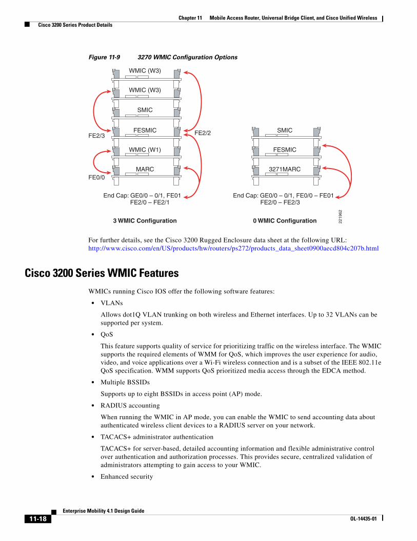
Figure 11-9 shows two configuration option examples for the Cisco 3270 MAR.
2219
61
11-17Enterprise Mobility 4.1 Design Guide
OL-14435-01
Chapter 11 Mobile Access Router, Universal Bridge Client, and Cisco Unified Wireless Cisco 3200 Series Product Details
Figure 11-9 3270 WMIC Configuration Options
For further details, see the Cisco 3200 Rugged Enclosure data sheet at the following URL: http://www.cisco.com/en/US/products/hw/routers/ps272/products_data_sheet0900aecd804c207b.html
Cisco 3200 Series WMIC FeaturesWMICs running Cisco IOS offer the following software features:
• VLANs
Allows dot1Q VLAN trunking on both wireless and Ethernet interfaces. Up to 32 VLANs can be supported per system.
• QoS
This feature supports quality of service for prioritizing traffic on the wireless interface. The WMIC supports the required elements of WMM for QoS, which improves the user experience for audio, video, and voice applications over a Wi-Fi wireless connection and is a subset of the IEEE 802.11e QoS specification. WMM supports QoS prioritized media access through the EDCA method.
• Multiple BSSIDs
Supports up to eight BSSIDs in access point (AP) mode.
• RADIUS accounting
When running the WMIC in AP mode, you can enable the WMIC to send accounting data about authenticated wireless client devices to a RADIUS server on your network.
• TACACS+ administrator authentication
TACACS+ for server-based, detailed accounting information and flexible administrative control over authentication and authorization processes. This provides secure, centralized validation of administrators attempting to gain access to your WMIC.
• Enhanced security
2219
62
WMIC (W3)
FESMIC
SMIC
WMIC (W1)
MARC
End Cap: GE0/0 – 0/1, FE01 FE2/0 – FE2/1
FE2/3
FE0/0
FE2/2
End Cap: GE0/0 – 0/1, FE0/0 – FE01 FE2/0 – FE2/3
3 WMIC Configuration 0 WMIC Configuration
WMIC (W3)
SMIC
FESMIC
3271MARC
11-18Enterprise Mobility 4.1 Design Guide
OL-14435-01
Chapter 11 Mobile Access Router, Universal Bridge Client, and Cisco Unified Wireless Cisco 3200 Series Product Details
Supports three advanced security features:
– WEP keys—Message Integrity Check (MIC) and WEP key hashing CKIP
– WPA
– WPA2
• Enhanced authentication services
Allows non-root bridges or workgroup bridges to authenticate to the network like other wireless client devices. After a network username and password for the non-root bridge or workgroup bridge are set, LEAP, EAP-TLS, or EAP-FAST can be used for authentication in dynamic WEP, WPA, or WPA2 configurations.
• 802.1x Authenticator
In AP mode, the MAR supports standard 802.1x EAP types for WLAN clients.
• Fast secure roaming
Uses CCKM in WGB mode and UWGB mode.
• Universal workgroup bridge
Supports interoperability with non-Cisco APs as a client.
• Repeater mode
Allows the access point to act as a wireless repeater to extend the coverage area of the wireless network.
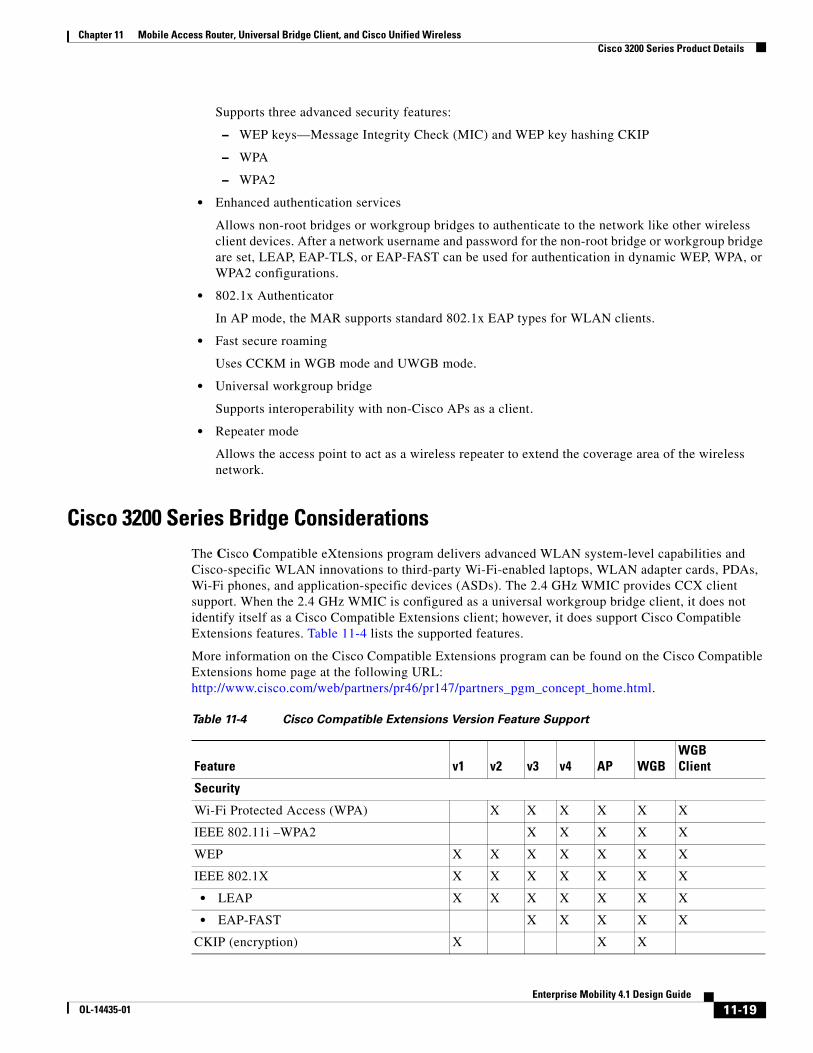
Cisco 3200 Series Bridge ConsiderationsThe Cisco Compatible eXtensions program delivers advanced WLAN system-level capabilities and Cisco-specific WLAN innovations to third-party Wi-Fi-enabled laptops, WLAN adapter cards, PDAs, Wi-Fi phones, and application-specific devices (ASDs). The 2.4 GHz WMIC provides CCX client support. When the 2.4 GHz WMIC is configured as a universal workgroup bridge client, it does not identify itself as a Cisco Compatible Extensions client; however, it does support Cisco Compatible Extensions features. Table 11-4 lists the supported features.
More information on the Cisco Compatible Extensions program can be found on the Cisco Compatible Extensions home page at the following URL: http://www.cisco.com/web/partners/pr46/pr147/partners_pgm_concept_home.html.
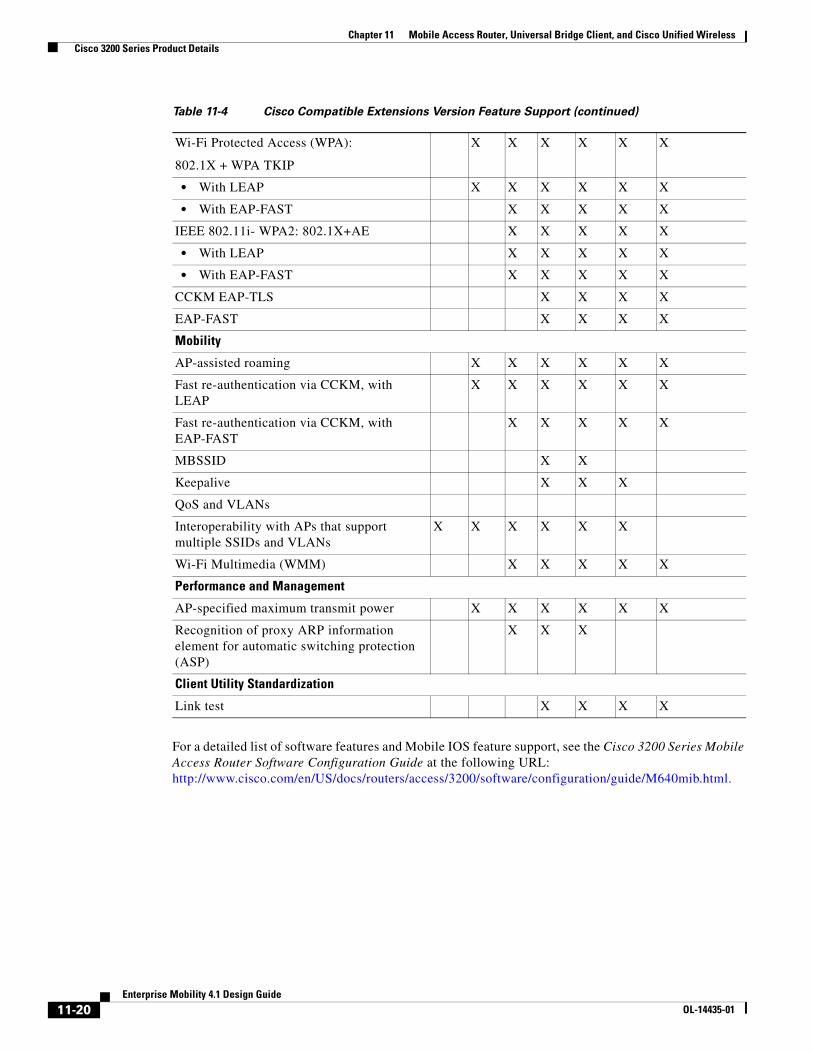
Table 11-4 Cisco Compatible Extensions Version Feature Support
Feature v1 v2 v3 v4 AP WGBWGBClient
Security
Wi-Fi Protected Access (WPA) X X X X X X
IEEE 802.11i –WPA2 X X X X X
WEP X X X X X X X
IEEE 802.1X X X X X X X X
• LEAP X X X X X X X
• EAP-FAST X X X X X
CKIP (encryption) X X X
11-19Enterprise Mobility 4.1 Design Guide
OL-14435-01
Chapter 11 Mobile Access Router, Universal Bridge Client, and Cisco Unified Wireless Cisco 3200 Series Product Details
For a detailed list of software features and Mobile IOS feature support, see the Cisco 3200 Series Mobile Access Router Software Configuration Guide at the following URL: http://www.cisco.com/en/US/docs/routers/access/3200/software/configuration/guide/M640mib.html.
Wi-Fi Protected Access (WPA):
802.1X + WPA TKIP
X X X X X X
• With LEAP X X X X X X
• With EAP-FAST X X X X X
IEEE 802.11i- WPA2: 802.1X+AE X X X X X
• With LEAP X X X X X
• With EAP-FAST X X X X X
CCKM EAP-TLS X X X X
EAP-FAST X X X X
Mobility
AP-assisted roaming X X X X X X
Fast re-authentication via CCKM, with LEAP
X X X X X X
Fast re-authentication via CCKM, with EAP-FAST
X X X X X
MBSSID X X
Keepalive X X X
QoS and VLANs
Interoperability with APs that support multiple SSIDs and VLANs
X X X X X X
Wi-Fi Multimedia (WMM) X X X X X
Performance and Management
AP-specified maximum transmit power X X X X X X
Recognition of proxy ARP information element for automatic switching protection (ASP)
X X X
Client Utility Standardization
Link test X X X X
Table 11-4 Cisco Compatible Extensions Version Feature Support (continued)
11-20Enterprise Mobility 4.1 Design Guide
OL-14435-01
Chapter 11 Mobile Access Router, Universal Bridge Client, and Cisco Unified Wireless Cisco 3200 Series Product Details
Cisco 3200 Series Management OptionsYou can manage the WMICs through the following interfaces:
• The IOS command-line interface (CLI), which you use through a PC running terminal emulation software or a Telnet/SSH session. IOS CLI is accessible through the WMIC console connection, Telnet, or SSH.
• Simple Network Management Protocol (SNMP)
• Web GUI management
11-21Enterprise Mobility 4.1 Design Guide
OL-14435-01

Chapter 11 Mobile Access Router, Universal Bridge Client, and Cisco Unified Wireless Cisco 3200 Series Product Details
11-22Enterprise Mobility 4.1 Design Guide
OL-14435-01