Embed Size (px)
Citation preview
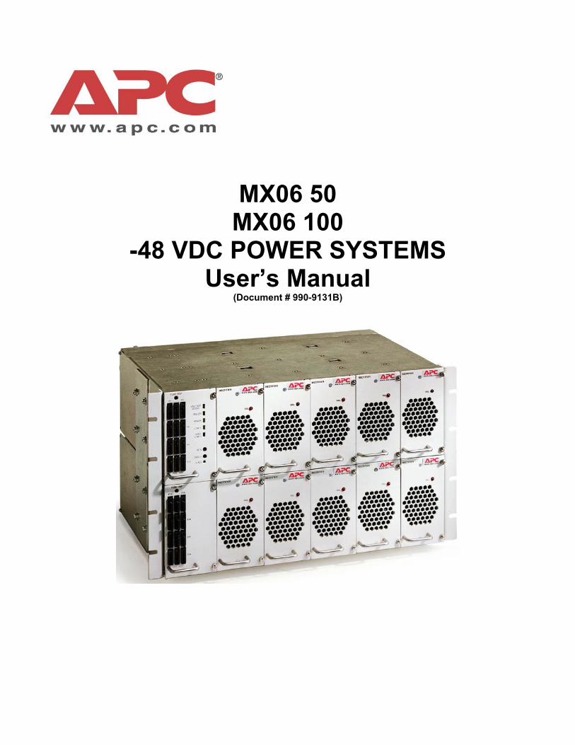
MX06 50 MX06 100
-48 VDC POWER SYSTEMS User’s Manual
(Document # 990-9131B)
MX06 Power Plant User’s Manual Page ii
Table of Contents
1 Safety First! 1
1.1. WARNING SYMBOLS .........................................................................................................1 1.2. GENERAL PRECAUTIONS:..................................................................................................1
2 Introduction 2 2.1. GENERAL INFORMATION....................................................................................................2 2.2. HOW TO USE THIS MANUAL ..............................................................................................4
3 Installation 5 3.1. UNPACKING EQUIPMENT ...................................................................................................5 3.2. MECHANICAL INSTALLATION ..............................................................................................5
Room / Location......................................................................................................................5 Mounting.................................................................................................................................5 Ventilation...............................................................................................................................6
3.3. AC POWER CONNECTIONS ...............................................................................................6 3.4. BATTERY CONNECTIONS...................................................................................................7
Planning the Battery installation..............................................................................................7 Connecting the Battery Cables ...............................................................................................7 Battery LVD Connection .........................................................................................................8 Multiple Battery Strings...........................................................................................................8 Battery Temperature Probe Installation ................................................................................10
3.5. DC SYSTEM GROUNDING ...............................................................................................10 3.6. LOAD PROTECTION INSTALLATION....................................................................................11
Circuit Breaker Installation....................................................................................................11 GMT Fuse Installation...........................................................................................................11
3.7. LOAD CONNECTIONS ......................................................................................................12 Cable Size Considerations ...................................................................................................12 Circuit Breaker Protected Load Connections (30 or 60 Amps) .............................................12 GMT Fuse protected Load Connections ...............................................................................13
3.8. INPUT / OUTPUT CONNECTIONS.......................................................................................13 Relay Output Connections....................................................................................................13 External Alarm Input Connections ........................................................................................14
3.9. RECTIFIER MODULE INSTALLATION...................................................................................15 3.10. INITIAL POWER-UP AND CHECKOUT .................................................................................15 3.11. BATTERY AND LOAD POWER UP.......................................................................................16
4 Technical Description 17 4.1. RECTIFIER MANAGEMENT................................................................................................17
AC Input Power.....................................................................................................................17 DC Output Power..................................................................................................................17 System Output Capacity .......................................................................................................17 Rectifier alarms reporting......................................................................................................17
4.2. SYSTEM MANAGEMENT...................................................................................................18 Control Functions..................................................................................................................18 Alarm Functions....................................................................................................................18 Displays ................................................................................................................................18
MX06 Power Plant User’s Manual Page iii
User Outputs.........................................................................................................................18 User Inputs ...........................................................................................................................19
4.3. LOAD MANAGEMENT.......................................................................................................19 4.4. BATTERY MANAGEMENT .................................................................................................19
Battery Charging...................................................................................................................19 Battery Temperature Compensation.....................................................................................19 Battery Low Voltage Disconnect ...........................................................................................20
5 Operation 21 5.1. DESCRIPTION.................................................................................................................21 5.2. MX06 OPERATION .........................................................................................................21
MX06 Voltage Adjustments ..................................................................................................21 MX06 External Alarm Input Configuration.............................................................................22
5.3. MX06-50 CONFIGURATION SETTINGS .............................................................................22 MX06-50 Rectifier Configuration...........................................................................................23 MX06-50 Programmable Alarms...........................................................................................23 MX06-50 Temperature Probe Selection ...............................................................................24
5.4. MX06-100 CONFIGURATION SETTINGS ...........................................................................24 MX06-100 Rectifier Configuration.........................................................................................24 MX06-100 Programmable Alarms.........................................................................................25 MX06-100 Temperature Probe Selection .............................................................................25
6 Specifications 26 6.1. AC INPUT ......................................................................................................................26
TWF0500H5401 Rectifier .....................................................................................................26 MX06 50 Power System .......................................................................................................26 MX06 100 Power System .....................................................................................................27
6.2. DC OUTPUT ..................................................................................................................27 TWF0500H5401 Rectifier .....................................................................................................27 MX06 50 Power System .......................................................................................................28 MX06 100 Power System .....................................................................................................28
6.3. CONTROLS AND INDICATORS ...........................................................................................29 TWF0500H5401 Rectifier .....................................................................................................29 MX06 Controller....................................................................................................................29
6.4. MECHANICAL .................................................................................................................29 TWF0500H5401 Rectifier .....................................................................................................29 Magnum VS 50 Power System.............................................................................................30 Magnum VS 100 Power System...........................................................................................30
6.5. ENVIRONMENTAL............................................................................................................30 6.6. COMPLIANCE .................................................................................................................31
7 APC Worldwide Customer Support 32 8 Limited Product Warranty 33
MX06 Power Plant User’s Manual Page iv
Revision History
Revision Date By Preliminary 15 FEB, 2000 SCG PML-0216A 07 APR, 2000 SCG PML-0216B 05 MAY, 2000 SCG PML-0216C 26 JUN, 2000 DRD PML-0216D 27 OCT, 2000 DRD 990-9131 Rev01 19 JAN, 2001 DRD 990-9131A Rev02 21 NOV, 2001 DRD / JF 990-9193A Rev03 15 FEB, 2002 JF 990-9131B Rev04 30 JUN, 2003 BT
Table of Figures
FIGURE 2.1-1 MX06 50 DC POWER PLANT ............................................................................................2 FIGURE 2.1-2 MX06 100 BLOCK DIAGRAM...........................................................................................3 FIGURE 3.3-1 AC INPUT WIRING KITS...................................................................................................6 FIGURE 3.4-1 BATTERY CABLE CONNECTION LOCATIONS............................................................8 FIGURE 3.4-2 MOTORIZED CIRCUIT BREAKER...................................................................................8 FIGURE 3.4-3 BATTERY WIRING DIAGRAM ........................................................................................9 FIGURE 3.4-4 BATTERY TEMPERATURE PROBE INSTALLATION ................................................10 FIGURE 3.6-1 GMT FUSE TEMPERATURE DE-RATING CHART......................................................11 FIGURE 3.6-2 GMT FUSES AVAILABLE FROM APC ..........................................................................11 FIGURE 3.7-1 CONNECTIONS TO CIRCUIT BREAKERS....................................................................12 FIGURE 3.7-2 CONNECTIONS TO GMT FUSES....................................................................................13 FIGURE 3.8-1 OUTPUT RELAY CONNECTIONS..................................................................................14 FIGURE 3.8-2 EXTERNAL USER INPUT CONNECTIONS...................................................................14 FIGURE 5.2-1 USER ALARM SETTINGS ...............................................................................................22 FIGURE 5.3-1 MX06-50 CONTROLLER LAYOUT ................................................................................22 FIGURE 5.3-2 MX06-50 JUMPER PROGRAMMING. ............................................................................23 FIGURE 5.3-3 MX06-50 ALARM JUMPERS ...........................................................................................23 FIGURE 5.4-1 MX06-100 CONTROLLER LAYOUT ..............................................................................24 FIGURE 5.4-2 MX06-100 JUMPER PROGRAMMING ...........................................................................25 FIGURE 5.4-3 MX06-100 ALARM JUMPERS .........................................................................................25
MX06 Power Plant User’s Manual Page 1
1 Safety First! It is very important to follow all safety procedures when unpacking, installing and operating any sort of power equipment. 1.1. Warning Symbols
CAUTION: An indication that special care is required to prevent injury, equipment damage or misuse
WARNING: An indication of an electrical hazard that may cause serious personal injury or death, catastrophic equipment damage or site destruction.
1.2. General Precautions:
WARNING: Hazardous AC voltage levels are present inside the power system. Keep the rear cover in place when the system is operational or energized
WARNING: Hazardous energy levels are present on bare conductors in the -48VDC distribution connection area of the plant. Accidental shorting of distribution conductors can cause arcing and high currents that can cause serious burns or other physical harm. It is recommended that:
• Remove any jewelry, rings or watches while working on this equipment.
• Use insulated wrenches, screwdrivers, cutters, pliers and other tools.
WARNING: Ensure that all of the DC and external AC circuit breakers are in the OFF position prior to connecting service to the power plant. Confirm that all voltages have been removed including any battery sources before proceeding.
Specific CAUTION and WARNING will be placed in manual where appropriate.
MX06 Power Plant User’s Manual Page 2
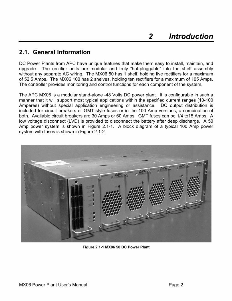
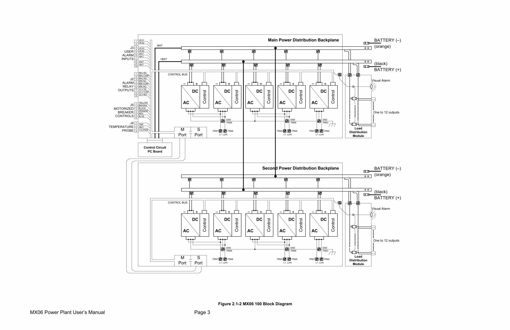
2 Introduction 2.1. General Information DC Power Plants from APC have unique features that make them easy to install, maintain, and upgrade. The rectifier units are modular and truly “hot-pluggable” into the shelf assembly without any separate AC wiring. The MX06 50 has 1 shelf, holding five rectifiers for a maximum of 52.5 Amps. The MX06 100 has 2 shelves, holding ten rectifiers for a maximum of 105 Amps. The controller provides monitoring and control functions for each component of the system. The APC MX06 is a modular stand-alone -48 Volts DC power plant. It is configurable in such a manner that it will support most typical applications within the specified current ranges (10-100 Amperes) without special application engineering or assistance. DC output distribution is included for circuit breakers or GMT style fuses or in the 100 Amp versions, a combination of both. Available circuit breakers are 30 Amps or 60 Amps. GMT fuses can be 1/4 to15 Amps. A low voltage disconnect (LVD) is provided to disconnect the battery after deep discharge. A 50 Amp power system is shown in Figure 2.1-1. A block diagram of a typical 100 Amp power system with fuses is shown in Figure 2.1-2.
Figure 2.1-1 MX06 50 DC Power Plant
MX06 Power Plant User’s Manual Page 3
AC
DC
Con
trol
AC
DC
Con
trol
AC
DC
Con
trol
AC
DC
Con
trol
AC
DC
Con
trol
J3USER
ALARMINPUTS
J2ALARMRELAY
OUTPUTS
J5MOTORIZED
BREAKERCONTROLS
J4TEMPERATURE
PROBE
BATTERY (+)
BATTERY (–)(orange)
(black)
UFA1UFA2
UFA3UFA4
123456789
10
-BAT-BAT
-BAT-BAT
123456789
MAJ NCMAJ COMMAJ NOMIN NCMIN COMMIN NOVLV NCVLV COMVLV NO
123456
YELLOWBROWNBLACKORANGEREDBLUE
TMP-BAT+12 PWR
1234
GND
L1 L2/N
GND
L1 L2/N
GND
L1 L2/N
One to 12 outputs
Visual Alarm
LoadDistribution
Module
CONTROL BUS
+BAT
-BAT
TRM1 TRM2
TRM3
TRM4 TRM5
TRM6
TRM7 TRM8
TRM9
MPort
SPort
Control CircuitPC Board
AC
DC
Con
trol
AC
DC
Con
trol
AC
DC
Con
trol
AC
DC
Con
trol
AC
DC
Con
trol
BATTERY (+)
BATTERY (–)(orange)
(black)
GND
L1 L2/N
GND
L1 L2/N
GND
L1 L2/N
One to 12 outputs
Visual Alarm
LoadDistribution
Module
CONTROL BUS
TRM1 TRM2
TRM3
TRM4 TRM5
TRM6
TRM7 TRM8
TRM9
MPort
SPort
Main Power Distribution Backplane
Second Power Distribution Backplane
Figure 2.1-2 MX06 100 Block Diagram
MX06 Power Plant User’s Manual Page 4
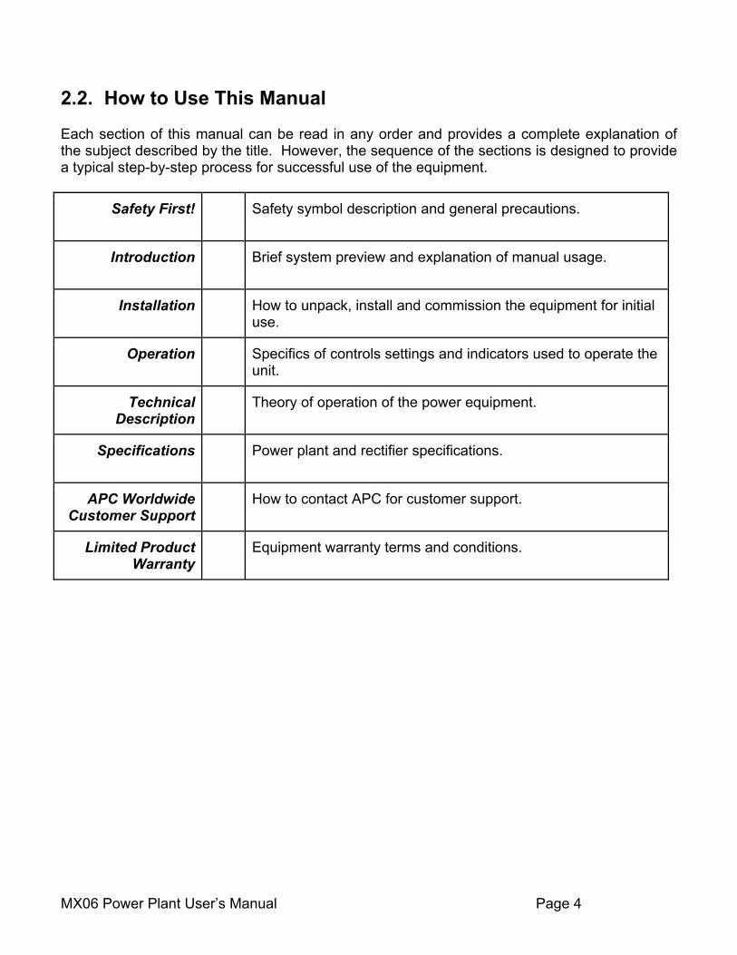
2.2. How to Use This Manual Each section of this manual can be read in any order and provides a complete explanation of the subject described by the title. However, the sequence of the sections is designed to provide a typical step-by-step process for successful use of the equipment.
Safety First! Safety symbol description and general precautions.
Introduction Brief system preview and explanation of manual usage.
Installation How to unpack, install and commission the equipment for initial use.
Operation Specifics of controls settings and indicators used to operate the unit.
Technical Description
Theory of operation of the power equipment.
Specifications Power plant and rectifier specifications.
APC Worldwide Customer Support
How to contact APC for customer support.
Limited Product Warranty
Equipment warranty terms and conditions.

MX06 Power Plant User’s Manual Page 5
3 Installation 3.1. Unpacking Equipment Remove equipment from packing material and inspect for shipping damage or missing items. It is important to report damage or material shortages to the shipping carrier while a representative is on site. If concealed damage or material shortages are found at a later time, contact the shipper to make arrangements for inspection and claim filing. Refer to Section 7 in the event it is necessary to return equipment to APC.
CAUTION: Appropriate lifting techniques and safety equipment should be used to remove equipment from packing.
PLEASE RECYCLE: The shipping materials can be recycled. Please save them for later use or dispose accordingly.
3.2. Mechanical Installation Room / Location NOTE: The APC DC power plant is to be installed in a room, vault, or similar enclosure that is accessible only to qualified persons in accordance with the regulatory authority having jurisdiction. Prior to installation, drawings, floor loading requirements, external alarm points, AC service entrance, and grounding schemes should all be checked and confirmed. If batteries are to be mounted in a room separate from the power plant, careful attention should be paid to battery cable voltage drop effects. Environmental operating temperatures and ventilation/cooling considerations should also be noted, not just for the power system but also for all other equipment that may reside in the power room area. Mounting The MX06 provides brackets to mount on a standard EIA 19-inch or 23-inch rack. Install the power system using hardware designed for the rack.
MX06 Power Plant User’s Manual Page 6
Ventilation The rectifier modules for this system have fans that provide front-to-rear airflow for internal cooling. The power system housing should be mounted such that there is free airflow to the front and back of the unit. [Refer to Section 6.5 for environmental characteristics.] Free airflow should be ensured so that the power system can provide full power at a given ambient temperature without de-rating. 3.3. AC Power Connections
WARNING: Ensure that all of the external DC and AC circuit breakers are in the OFF position prior to connecting service to the power plant. Confirm that all voltages have been removed including any battery sources before proceeding. Keep the rear cover in place when the system is operational or energized.
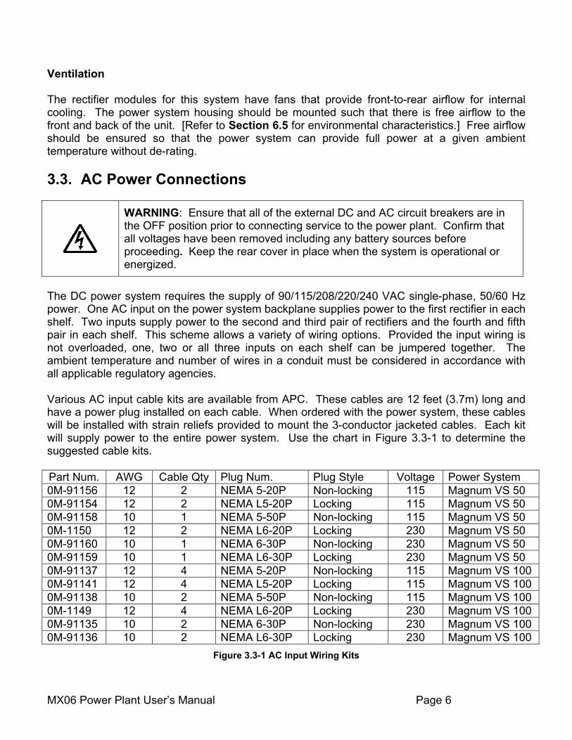
The DC power system requires the supply of 90/115/208/220/240 VAC single-phase, 50/60 Hz power. One AC input on the power system backplane supplies power to the first rectifier in each shelf. Two inputs supply power to the second and third pair of rectifiers and the fourth and fifth pair in each shelf. This scheme allows a variety of wiring options. Provided the input wiring is not overloaded, one, two or all three inputs on each shelf can be jumpered together. The ambient temperature and number of wires in a conduit must be considered in accordance with all applicable regulatory agencies. Various AC input cable kits are available from APC. These cables are 12 feet (3.7m) long and have a power plug installed on each cable. When ordered with the power system, these cables will be installed with strain reliefs provided to mount the 3-conductor jacketed cables. Each kit will supply power to the entire power system. Use the chart in Figure 3.3-1 to determine the suggested cable kits. Part Num. AWG Cable Qty Plug Num. Plug Style Voltage Power System 0M-91156 12 2 NEMA 5-20P Non-locking 115 Magnum VS 50 0M-91154 12 2 NEMA L5-20P Locking 115 Magnum VS 50 0M-91158 10 1 NEMA 5-50P Non-locking 115 Magnum VS 50 0M-1150 12 2 NEMA L6-20P Locking 230 Magnum VS 50 0M-91160 10 1 NEMA 6-30P Non-locking 230 Magnum VS 50 0M-91159 10 1 NEMA L6-30P Locking 230 Magnum VS 50 0M-91137 12 4 NEMA 5-20P Non-locking 115 Magnum VS 100 0M-91141 12 4 NEMA L5-20P Locking 115 Magnum VS 100 0M-91138 10 2 NEMA 5-50P Non-locking 115 Magnum VS 100 0M-1149 12 4 NEMA L6-20P Locking 230 Magnum VS 100 0M-91135 10 2 NEMA 6-30P Non-locking 230 Magnum VS 100 0M-91136 10 2 NEMA L6-30P Locking 230 Magnum VS 100
Figure 3.3-1 AC Input Wiring Kits
MX06 Power Plant User’s Manual Page 7
3.4. Battery Connections
WARNING: Hazardous energy levels are present on bare conductors in the -48VDC distribution connection area of the plant. Accidental shorting of distribution conductors can cause arcing and high currents that can cause serious burns or other physical harm. It is recommended that:
• Remove any jewelry, rings or watches while working on this equipment.
• Use insulated wrenches, screwdrivers, cutters, pliers and other tools. Planning the Battery installation The battery cable(s) should be sized to limit the voltage drop from the DC power plant to the battery during charging per system design requirements. The cable(s) must also carry the full load current during battery operation. If assistance is required to determine the necessary cables for the application, contact your sales representative or APC (Refer to Chapter 7 for APC Customer Support information. An external fuse or circuit breaker (various options are available from APC) is recommended in the negative line (located at the battery end) to protect the cables from the battery to the DC power plant. The power plant can monitor auxiliary contacts from this breaker. Connecting the Battery Cables
WARNING: Make certain that the battery polarity is correct when making connections to the DC power plant. Incorrect connection could cause severe equipment damage.
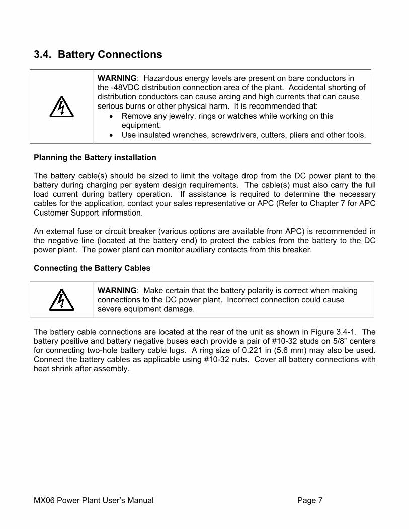
The battery cable connections are located at the rear of the unit as shown in Figure 3.4-1. The battery positive and battery negative buses each provide a pair of #10-32 studs on 5/8” centers for connecting two-hole battery cable lugs. A ring size of 0.221 in (5.6 mm) may also be used. Connect the battery cables as applicable using #10-32 nuts. Cover all battery connections with heat shrink after assembly.
MX06 Power Plant User’s Manual Page 8
Figure 3.4-1 Battery Cable Connection Locations
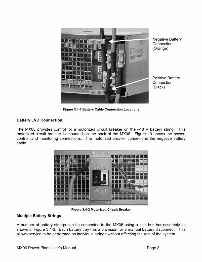
Battery LVD Connection The MX06 provides control for a motorized circuit breaker on the –48 V battery string. This motorized circuit breaker is mounted on the back of the MX06. Figure 10 shows the power, control, and monitoring connections. The motorized breaker connects in the negative battery cable.
Figure 3.4-2 Motorized Circuit Breaker
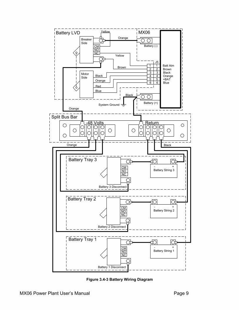
Multiple Battery Strings A number of battery strings can be connected to the MX06 using a split bus bar assembly as shown in Figure 3.4-3. Each battery tray has a provision for a manual battery disconnect. This allows service to be performed on individual strings without affecting the rest of the system.
Positive Battery Connection (Black)
Negative Battery Connection (Orange)
MX06 Power Plant User’s Manual Page 9
CMNONC
Yellow
Yellow
Brown
Orange
1 1 Batt Alm2 2 Brown3 3 Black4 4 Orange5 5 +BAT6 6 Blue
BlackOrange
RedBlue
MX06BreakerSide
MotorSide
J5
Battery LVD
CMNONC
Battery 3 Disconnect
- +Battery String 3
CMNONC
Battery 2 Disconnect
- +Battery String 2
CMNONC
Battery 1 Disconnect
- +Battery String 1
Battery (-)
Battery (+)
Black
Split Bus Bar
Battery Tray 3
Battery Tray 2
Battery Tray 1
Orange
Orange Black
System Ground
-48 Volts Return
Figure 3.4-3 Battery Wiring Diagram
MX06 Power Plant User’s Manual Page 10
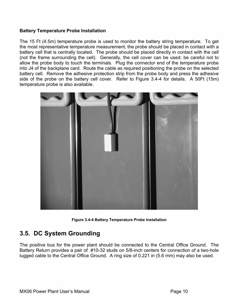
Battery Temperature Probe Installation The 15 Ft (4.5m) temperature probe is used to monitor the battery string temperature. To get the most representative temperature measurement, the probe should be placed in contact with a battery cell that is centrally located. The probe should be placed directly in contact with the cell (not the frame surrounding the cell). Generally, the cell cover can be used; be careful not to allow the probe body to touch the terminals. Plug the connector end of the temperature probe into J4 of the backplane card. Route the cable as required positioning the probe on the selected battery cell. Remove the adhesive protection strip from the probe body and press the adhesive side of the probe on the battery cell cover. Refer to Figure 3.4-4 for details. A 50Ft (15m) temperature probe is also available.
Figure 3.4-4 Battery Temperature Probe Installation
3.5. DC System Grounding The positive bus for the power plant should be connected to the Central Office Ground. The Battery Return provides a pair of #10-32 studs on 5/8-inch centers for connection of a two-hole lugged cable to the Central Office Ground. A ring size of 0.221 in (5.6 mm) may also be used.
MX06 Power Plant User’s Manual Page 11
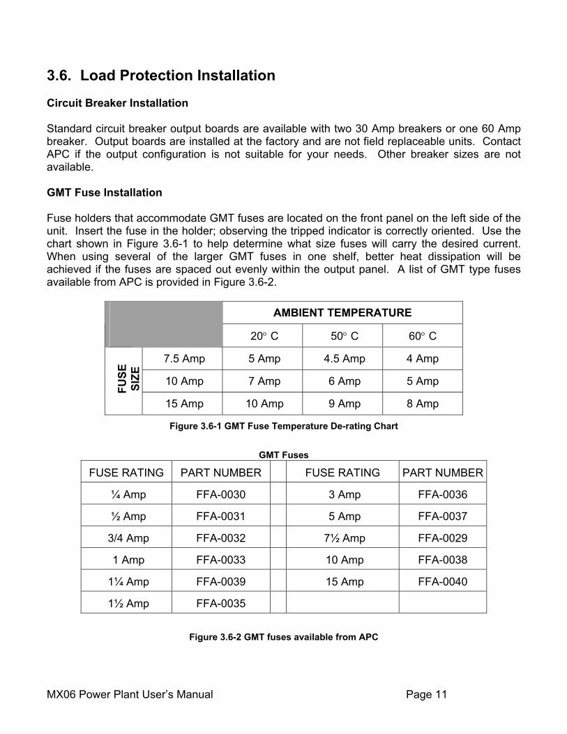
3.6. Load Protection Installation Circuit Breaker Installation Standard circuit breaker output boards are available with two 30 Amp breakers or one 60 Amp breaker. Output boards are installed at the factory and are not field replaceable units. Contact APC if the output configuration is not suitable for your needs. Other breaker sizes are not available. GMT Fuse Installation Fuse holders that accommodate GMT fuses are located on the front panel on the left side of the unit. Insert the fuse in the holder; observing the tripped indicator is correctly oriented. Use the chart shown in Figure 3.6-1 to help determine what size fuses will carry the desired current. When using several of the larger GMT fuses in one shelf, better heat dissipation will be achieved if the fuses are spaced out evenly within the output panel. A list of GMT type fuses available from APC is provided in Figure 3.6-2.
AMBIENT TEMPERATURE
20° C 50° C 60° C
7.5 Amp 5 Amp 4.5 Amp 4 Amp
10 Amp 7 Amp 6 Amp 5 Amp
FUSE
SI
ZE
15 Amp 10 Amp 9 Amp 8 Amp
Figure 3.6-1 GMT Fuse Temperature De-rating Chart
GMT Fuses
FUSE RATING PART NUMBER FUSE RATING PART NUMBER
¼ Amp FFA-0030 3 Amp FFA-0036
½ Amp FFA-0031 5 Amp FFA-0037
3/4 Amp FFA-0032 7½ Amp FFA-0029
1 Amp FFA-0033 10 Amp FFA-0038
1¼ Amp FFA-0039 15 Amp FFA-0040
1½ Amp FFA-0035
Figure 3.6-2 GMT fuses available from APC
MX06 Power Plant User’s Manual Page 12
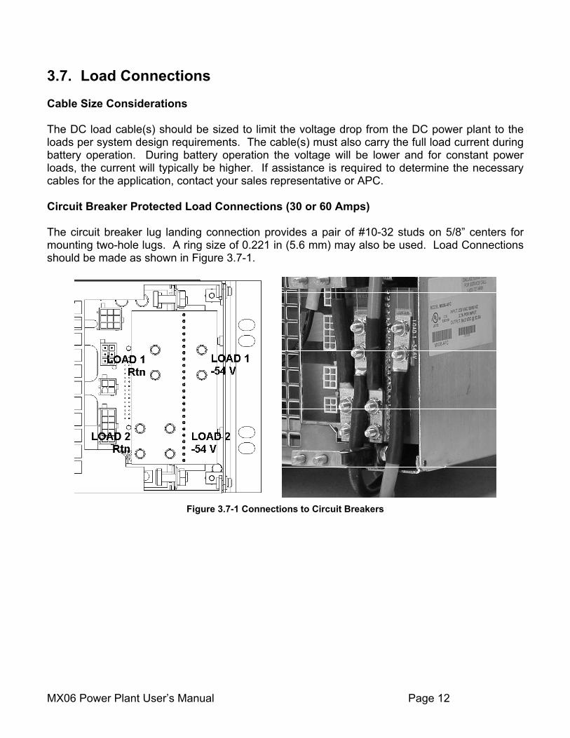
3.7. Load Connections Cable Size Considerations The DC load cable(s) should be sized to limit the voltage drop from the DC power plant to the loads per system design requirements. The cable(s) must also carry the full load current during battery operation. During battery operation the voltage will be lower and for constant power loads, the current will typically be higher. If assistance is required to determine the necessary cables for the application, contact your sales representative or APC. Circuit Breaker Protected Load Connections (30 or 60 Amps) The circuit breaker lug landing connection provides a pair of #10-32 studs on 5/8” centers for mounting two-hole lugs. A ring size of 0.221 in (5.6 mm) may also be used. Load Connections should be made as shown in Figure 3.7-1.
Figure 3.7-1 Connections to Circuit Breakers
MX06 Power Plant User’s Manual Page 13
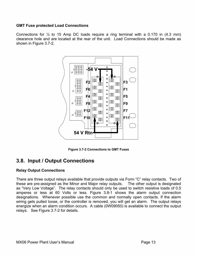
GMT Fuse protected Load Connections Connections for ¼ to 15 Amp DC loads require a ring terminal with a 0.170 in (4.3 mm) clearance hole and are located at the rear of the unit. Load Connections should be made as shown in Figure 3.7-2.
J2
J3
J5
J4
F3
F1
F5
F9
F7
F11
F2
F6
F4
F8
F12
F10
-54 V
54 V Rtn
Figure 3.7-2 Connections to GMT Fuses
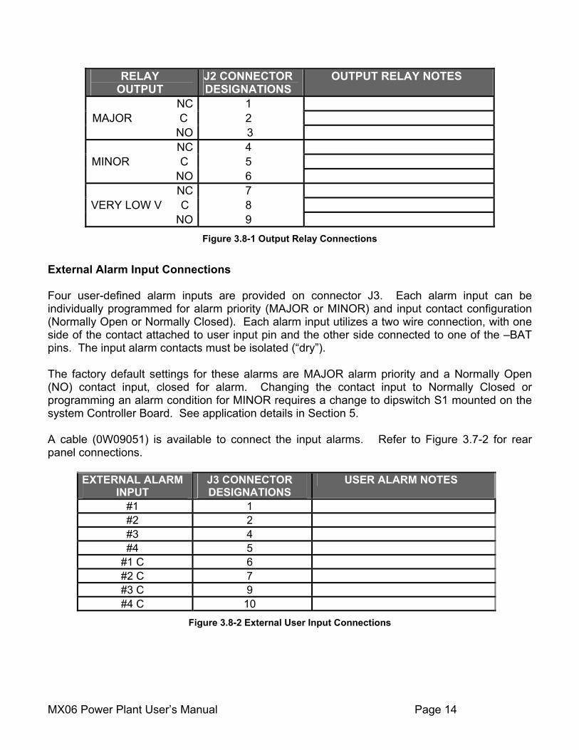
3.8. Input / Output Connections Relay Output Connections There are three output relays available that provide outputs via Form “C” relay contacts. Two of these are pre-assigned as the Minor and Major relay outputs. The other output is designated as “Very Low Voltage”. The relay contacts should only be used to switch resistive loads of 0.5 amperes or less at 60 Volts or less. Figure 3.8-1 shows the alarm output connection designations. Whenever possible use the common and normally open contacts. If the alarm wiring gets pulled loose, or the controller is removed, you will get an alarm. The output relays energize when an alarm condition occurs. A cable (0W09050) is available to connect the output relays. See Figure 3.7-2 for details.
MX06 Power Plant User’s Manual Page 14
RELAY OUTPUT
J2 CONNECTOR DESIGNATIONS
OUTPUT RELAY NOTES
NC 1 MAJOR C 2
NO 3 NC 4
MINOR C 5 NO 6 NC 7
VERY LOW V C 8 NO 9
Figure 3.8-1 Output Relay Connections
External Alarm Input Connections Four user-defined alarm inputs are provided on connector J3. Each alarm input can be individually programmed for alarm priority (MAJOR or MINOR) and input contact configuration (Normally Open or Normally Closed). Each alarm input utilizes a two wire connection, with one side of the contact attached to user input pin and the other side connected to one of the –BAT pins. The input alarm contacts must be isolated (“dry”). The factory default settings for these alarms are MAJOR alarm priority and a Normally Open (NO) contact input, closed for alarm. Changing the contact input to Normally Closed or programming an alarm condition for MINOR requires a change to dipswitch S1 mounted on the system Controller Board. See application details in Section 5. A cable (0W09051) is available to connect the input alarms. Refer to Figure 3.7-2 for rear panel connections.
EXTERNAL ALARM INPUT
J3 CONNECTOR DESIGNATIONS
USER ALARM NOTES
#1 1 #2 2 #3 4 #4 5
#1 C 6 #2 C 7 #3 C 9 #4 C 10
Figure 3.8-2 External User Input Connections
MX06 Power Plant User’s Manual Page 15
3.9. Rectifier Module Installation
WARNING: Rectifier DC output circuits will be damaged if battery is installed incorrectly. Before rectifier installation, ensure proper battery polarity and that the battery is isolated from the rest of the system
The rectifier modules are generally shipped in separate containers. Follow the procedure below to install a rectifier module. Rectifiers may be installed even when the system is energized.
1) Remove the cover plate (if present) from the position where the rectifier will be added. 2) Remove the rectifier from its shipping container. 3) Slide the rectifier module into the shelf between the guides until it is fully seated. 4) Fasten the rectifier in place with the captive rectifier retaining screws.
5) Enable that rectifier position for monitoring by removing the system Controller Board and
setting the dipswitch S2 position corresponding to the new rectifier position from “ON” to “OFF” (if there are 10 little switches then the operate in pairs. The rectifiers are numbered on the top row, left to right as 1 through 5; and on the bottom row, left to right 6 to 10, when facing the front of the system. See Section 5 for additional details concerning the setup of the system Controller Board.
Since all adjustments are made from the system controller, no rectifier adjustments are necessary. 3.10. Initial Power-Up and Checkout Before initiating power-up and checkout, ensure that the following conditions exist:
1) Make sure that the external circuit breaker protecting the cables from the battery to the power plant are turned OFF (the battery cables should be connected to the power plant, but the battery should not be connected).
2) Make sure that all load circuit breakers are turned OFF and fuses are removed.
3) Verify that all rectifiers have been installed.
4) Apply AC Power by turning on the circuit breakers that supply AC power to the rectifiers in the power plant.
MX06 Power Plant User’s Manual Page 16
5) Use a Digital voltmeter to measure the system voltage using the “RTN” (+) and ”-NEG V” (-) test points on the front panel. The voltage is set at the factory for –54.0 V dc. Use the “V ADJ” potentiometer to set the voltage to the desired level.
3.11. Battery and Load Power up After the initial checkout has been performed, the following steps are followed to complete the system power up procedure. 1) Turn on the external circuit breaker from the battery to the power plant.
2) Load circuit protection may now be enabled as required.
MX06 Power Plant User’s Manual Page 17
4 Technical Description The various MX06 models are modular stand-alone –48 V dc power plants. Each can be configured to support most typical applications within their specified current capacity without special application engineering or assistance. Output distribution is provided through the use of up to 12 plug-in GMT-type fuses per shelf or up to two circuit breakers per shelf. A control port is also available to operate an optional motorized circuit breaker designed to provide battery cable protection and low voltage disconnect (LVD) for a battery string(s). 4.1. Rectifier Management AC Input Power The basic component of the power system is the rectifier module, which rectifies utility AC into nominal 48 Volts DC. Each rectifier module requires 90/115/208/220/240 Volt AC single-phase, 50/60 Hz. Available cord sets include a variety of blade and twist lock plugs. Dedicated wiring inside conduit can also be used. DC Output Power The DC outputs of all the rectifiers in the system are connected to a common bus that is rated to carry the current of the entire system. The rectifier modules will equally share the entire load, independent of the controller. The rectifiers will continue to provide DC power if the controller is removed or fails. System Output Capacity The power plant has two basic configurations: The MX06 50 power plant supplies a maximum of 52.5 amps or 42 amps with N+1 redundancy. The housing for this configuration provides one rectifier shelf with integrated DC output distribution, and controller. The MX06-100 power plant supplies a maximum of 105 amps or 94.5 amps with N+1 redundancy. The housing for this configuration provides two rectifier shelves with integrated DC output distribution, and controller. Rectifier alarms reporting The rectifier has numerous sensors inside the unit that monitor AC fail, low voltage, etc. These rectifier sensors trigger outputs that are monitored by the controller. The controller can trigger output relays in the event of a rectifier alarm.
MX06 Power Plant User’s Manual Page 18
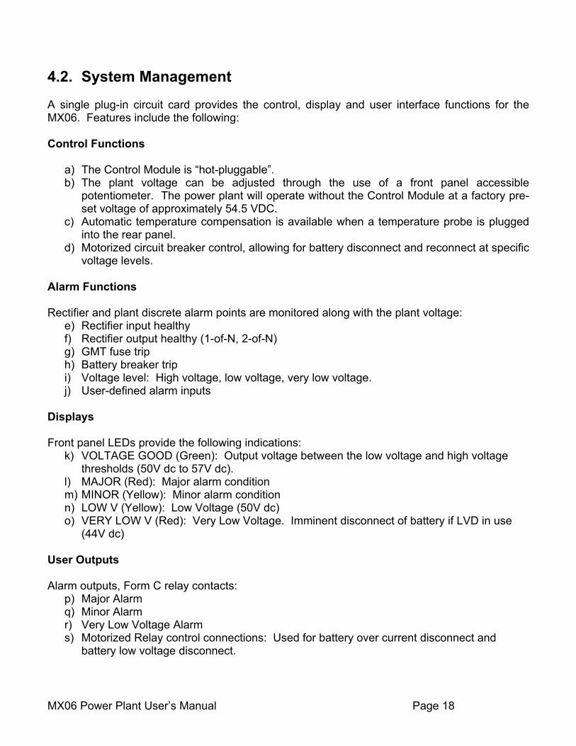
4.2. System Management A single plug-in circuit card provides the control, display and user interface functions for the MX06. Features include the following: Control Functions
a) The Control Module is “hot-pluggable”. b) The plant voltage can be adjusted through the use of a front panel accessible
potentiometer. The power plant will operate without the Control Module at a factory pre-set voltage of approximately 54.5 VDC.
c) Automatic temperature compensation is available when a temperature probe is plugged into the rear panel.
d) Motorized circuit breaker control, allowing for battery disconnect and reconnect at specific voltage levels.
Alarm Functions Rectifier and plant discrete alarm points are monitored along with the plant voltage:
e) Rectifier input healthy f) Rectifier output healthy (1-of-N, 2-of-N) g) GMT fuse trip h) Battery breaker trip i) Voltage level: High voltage, low voltage, very low voltage. j) User-defined alarm inputs
Displays Front panel LEDs provide the following indications:
k) VOLTAGE GOOD (Green): Output voltage between the low voltage and high voltage thresholds (50V dc to 57V dc).
l) MAJOR (Red): Major alarm condition m) MINOR (Yellow): Minor alarm condition n) LOW V (Yellow): Low Voltage (50V dc) o) VERY LOW V (Red): Very Low Voltage. Imminent disconnect of battery if LVD in use
(44V dc)
User Outputs Alarm outputs, Form C relay contacts:
p) Major Alarm q) Minor Alarm r) Very Low Voltage Alarm s) Motorized Relay control connections: Used for battery over current disconnect and
battery low voltage disconnect.
MX06 Power Plant User’s Manual Page 19
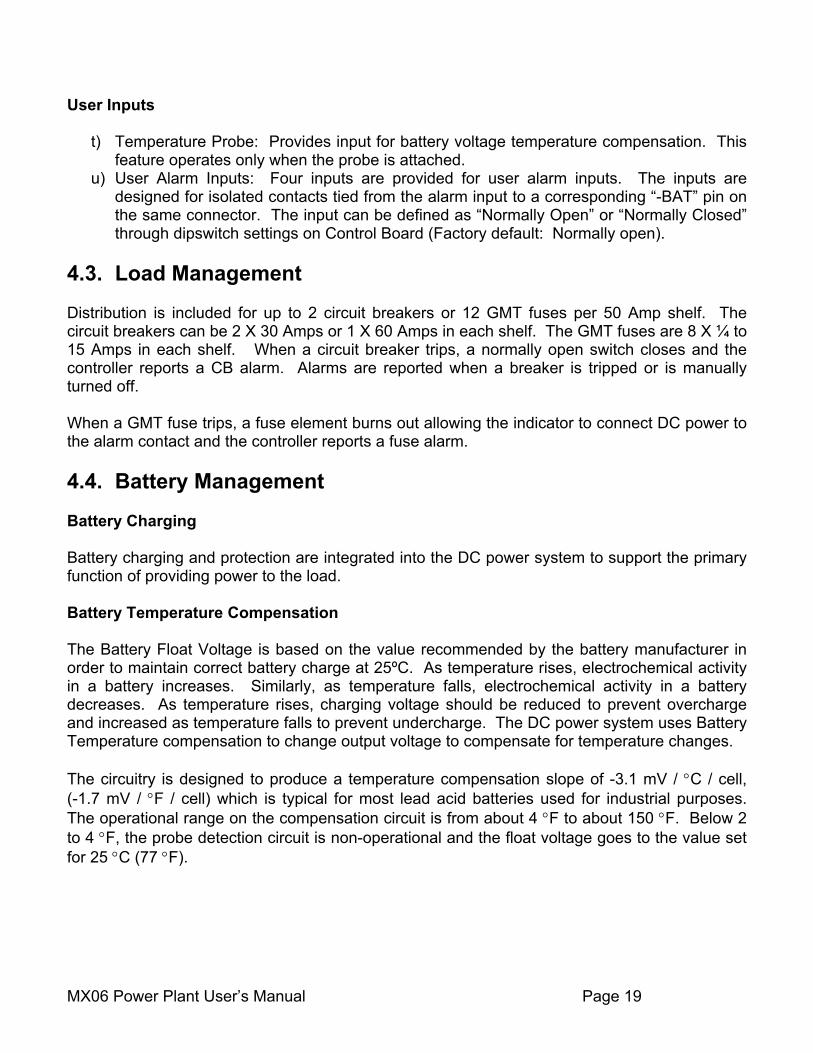
User Inputs
t) Temperature Probe: Provides input for battery voltage temperature compensation. This feature operates only when the probe is attached.
u) User Alarm Inputs: Four inputs are provided for user alarm inputs. The inputs are designed for isolated contacts tied from the alarm input to a corresponding “-BAT” pin on the same connector. The input can be defined as “Normally Open” or “Normally Closed” through dipswitch settings on Control Board (Factory default: Normally open).
4.3. Load Management Distribution is included for up to 2 circuit breakers or 12 GMT fuses per 50 Amp shelf. The circuit breakers can be 2 X 30 Amps or 1 X 60 Amps in each shelf. The GMT fuses are 8 X ¼ to 15 Amps in each shelf. When a circuit breaker trips, a normally open switch closes and the controller reports a CB alarm. Alarms are reported when a breaker is tripped or is manually turned off. When a GMT fuse trips, a fuse element burns out allowing the indicator to connect DC power to the alarm contact and the controller reports a fuse alarm. 4.4. Battery Management Battery Charging Battery charging and protection are integrated into the DC power system to support the primary function of providing power to the load. Battery Temperature Compensation The Battery Float Voltage is based on the value recommended by the battery manufacturer in order to maintain correct battery charge at 25ºC. As temperature rises, electrochemical activity in a battery increases. Similarly, as temperature falls, electrochemical activity in a battery decreases. As temperature rises, charging voltage should be reduced to prevent overcharge and increased as temperature falls to prevent undercharge. The DC power system uses Battery Temperature compensation to change output voltage to compensate for temperature changes. The circuitry is designed to produce a temperature compensation slope of -3.1 mV / °C / cell, (-1.7 mV / °F / cell) which is typical for most lead acid batteries used for industrial purposes. The operational range on the compensation circuit is from about 4 °F to about 150 °F. Below 2 to 4 °F, the probe detection circuit is non-operational and the float voltage goes to the value set for 25 °C (77 °F).
MX06 Power Plant User’s Manual Page 20
Battery Low Voltage Disconnect In order to prevent damage to the battery due to deep discharge, the DC power system has hardware support for a battery Low Voltage Disconnect (LVD). A battery LVD has the loads attached to the rectifiers and the battery is disconnected from the system. The MX06 provides control for a motorized circuit breaker on the –48 V battery string. This motorized circuit breaker is mounted on the back of the MX06. Figure 10 shows the power, control, and monitoring connections. The controller will turn the motorized breaker off in a low voltage condition to protect the battery. It can also be turned off manually as you would a non-motorized breaker. In the event of an over-current situation the breaker will trip like a normal breaker.
MX06 Power Plant User’s Manual Page 21
5 Operation 5.1. Description The MX06 is designed for years of operation with no user input. The power system is pre-set at the factory with all parameters needed for normal operation. The front panel LEDs and the alarm output relays, indicate the general health of the unit. Voltage adjustments or changes to switch settings on the system Controller Board are only required under the follow conditions:
Rectifiers are added or removed from the original configuration shipped from the factory. Modifications are required to the User Alarm Input settings (alarm priority or input contact
sense). Voltage threshold levels for alarm conditions or motorized breaker control need to be
changed from the factory default settings. 5.2. MX06 Operation The control card for the MX06-50 is different than the control card for the MX06-100 due to increased number of rectifiers in the MX06-100. The control card for the MX06 is the 0P9172 and for the MX06-100, the control card is the 0P9745. This section will deal with configurations applicable to all MX06 power systems. MX06 Voltage Adjustments Power plant voltage level is the only adjustment required on a standard MX06. This is performed using the “V ADJ” potentiometer on the front panel of the Control / Distribution module. The voltage level should be set to accommodate the float voltage required by the battery being used in the power system. Consult the battery manufacturer’s data sheet to get the operating voltage information.
MX06 Power Plant User’s Manual Page 22
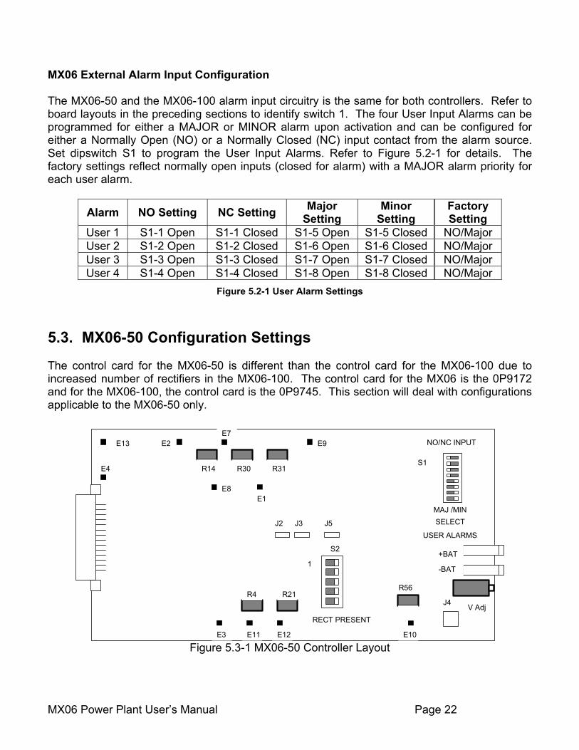
MX06 External Alarm Input Configuration The MX06-50 and the MX06-100 alarm input circuitry is the same for both controllers. Refer to board layouts in the preceding sections to identify switch 1. The four User Input Alarms can be programmed for either a MAJOR or MINOR alarm upon activation and can be configured for either a Normally Open (NO) or a Normally Closed (NC) input contact from the alarm source. Set dipswitch S1 to program the User Input Alarms. Refer to Figure 5.2-1 for details. The factory settings reflect normally open inputs (closed for alarm) with a MAJOR alarm priority for each user alarm.
Alarm NO Setting NC Setting Major Setting
Minor Setting
Factory Setting
User 1 S1-1 Open S1-1 Closed S1-5 Open S1-5 Closed NO/Major User 2 S1-2 Open S1-2 Closed S1-6 Open S1-6 Closed NO/Major User 3 S1-3 Open S1-3 Closed S1-7 Open S1-7 Closed NO/Major User 4 S1-4 Open S1-4 Closed S1-8 Open S1-8 Closed NO/Major
Figure 5.2-1 User Alarm Settings
5.3. MX06-50 Configuration Settings The control card for the MX06-50 is different than the control card for the MX06-100 due to increased number of rectifiers in the MX06-100. The control card for the MX06 is the 0P9172 and for the MX06-100, the control card is the 0P9745. This section will deal with configurations applicable to the MX06-50 only.
S2
1
RECT PRESENT
MAJ /MINSELECT
NO/NC INPUT
USER ALARMS
E13
E4
E8E1
E9E7
E2
E3 E11 E12 E10
S1R31R30R14
R21R4R56
V Adj
-BAT
+BAT
J2 J3 J5
J4
Figure 5.3-1 MX06-50 Controller Layout
MX06 Power Plant User’s Manual Page 23
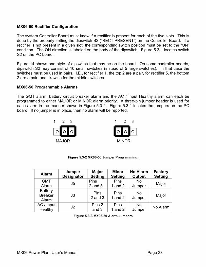
MX06-50 Rectifier Configuration The system Controller Board must know if a rectifier is present for each of the five slots. This is done by the properly setting the dipswitch S2 (“RECT PRESENT”) on the Controller Board. If a rectifier is not present in a given slot, the corresponding switch position must be set to the “ON” condition. The ON direction is labeled on the body of the dipswitch. Figure 5.3-1 locates switch S2 on the PC board. Figure 14 shows one style of dipswitch that may be on the board. On some controller boards, dipswitch S2 may consist of 10 small switches (instead of 5 large switches). In that case the switches must be used in pairs. I.E., for rectifier 1, the top 2 are a pair, for rectifier 5, the bottom 2 are a pair, and likewise for the middle switches. MX06-50 Programmable Alarms The GMT alarm, battery circuit breaker alarm and the AC / Input Healthy alarm can each be programmed to either MAJOR or MINOR alarm priority. A three-pin jumper header is used for each alarm in the manner shown in Figure 5.3-2. Figure 5.3-1 locates the jumpers on the PC board. If no jumper is in place, then no alarm will be reported.
Figure 5.3-2 MX06-50 Jumper Programming.
Alarm Jumper Designator
Major Setting
Minor Setting
No Alarm Output
Factory Setting
GMT Alarm J5 Pins
2 and 3 Pins
1 and 2 No
Jumper Major
Battery Breaker Alarm
J3 Pins 2 and 3
Pins 1 and 2
No Jumper Major
AC / Input Healthy J2 Pins 2
and 3 Pins
1 and 2 No
Jumper No Alarm
Figure 5.3-3 MX06-50 Alarm Jumpers
MAJOR
1 2 3
MINOR
1 2 3
MX06 Power Plant User’s Manual Page 24
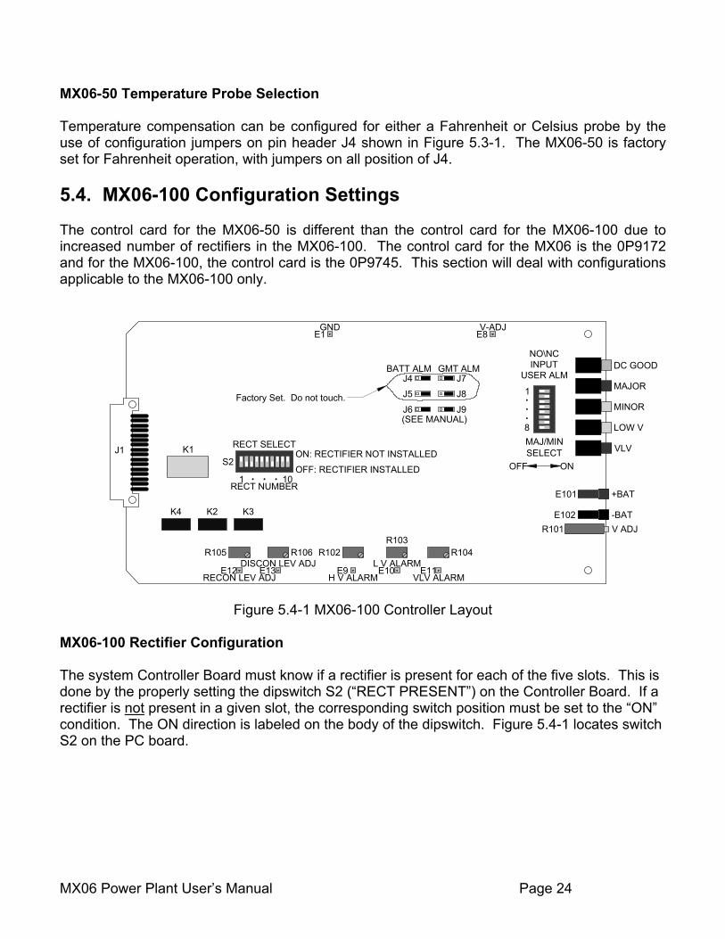
MX06-50 Temperature Probe Selection Temperature compensation can be configured for either a Fahrenheit or Celsius probe by the use of configuration jumpers on pin header J4 shown in Figure 5.3-1. The MX06-50 is factory set for Fahrenheit operation, with jumpers on all position of J4. 5.4. MX06-100 Configuration Settings The control card for the MX06-50 is different than the control card for the MX06-100 due to increased number of rectifiers in the MX06-100. The control card for the MX06 is the 0P9172 and for the MX06-100, the control card is the 0P9745. This section will deal with configurations applicable to the MX06-100 only.
E101
E102R101
DC GOOD
MAJOR
MINOR
LOW V
VLV
+BAT
-BATV ADJ
NO\NCINPUT
USER ALM
MAJ/MINSELECT
ONOFF
1
8
J1 K1
K4 K2 K3
S2
RECT SELECTON: RECTIFIER NOT INSTALLEDOFF: RECTIFIER INSTALLED
1 10RECT NUMBER
GMT ALMBATT ALMJ4J5J6
J7J8J9
(SEE MANUAL)
Factory Set. Do not touch.
RECON LEV ADJDISCON LEV ADJ
E12 E13H V ALARM
L V ALARMVLV ALARM
E9 E10 E11
R105 R106 R102R103
E1GND
R104
E8V-ADJ
Figure 5.4-1 MX06-100 Controller Layout
MX06-100 Rectifier Configuration The system Controller Board must know if a rectifier is present for each of the five slots. This is done by the properly setting the dipswitch S2 (“RECT PRESENT”) on the Controller Board. If a rectifier is not present in a given slot, the corresponding switch position must be set to the “ON” condition. The ON direction is labeled on the body of the dipswitch. Figure 5.4-1 locates switch S2 on the PC board.
MX06 Power Plant User’s Manual Page 25
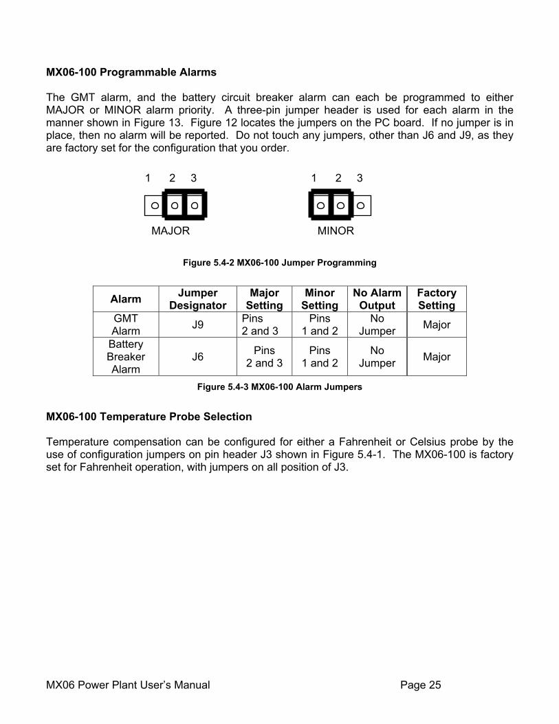
MX06-100 Programmable Alarms The GMT alarm, and the battery circuit breaker alarm can each be programmed to either MAJOR or MINOR alarm priority. A three-pin jumper header is used for each alarm in the manner shown in Figure 13. Figure 12 locates the jumpers on the PC board. If no jumper is in place, then no alarm will be reported. Do not touch any jumpers, other than J6 and J9, as they are factory set for the configuration that you order.
Figure 5.4-2 MX06-100 Jumper Programming
Alarm Jumper Designator
Major Setting
Minor Setting
No Alarm Output
Factory Setting
GMT Alarm J9 Pins
2 and 3 Pins
1 and 2 No
Jumper Major
Battery Breaker Alarm
J6 Pins 2 and 3
Pins 1 and 2
No Jumper Major
Figure 5.4-3 MX06-100 Alarm Jumpers
MX06-100 Temperature Probe Selection Temperature compensation can be configured for either a Fahrenheit or Celsius probe by the use of configuration jumpers on pin header J3 shown in Figure 5.4-1. The MX06-100 is factory set for Fahrenheit operation, with jumpers on all position of J3.
MAJOR
1 2 3
MINOR
1 2 3
MX06 Power Plant User’s Manual Page 26
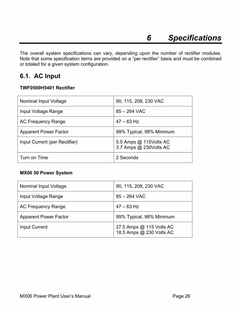
6 Specifications The overall system specifications can vary, depending upon the number of rectifier modules. Note that some specification items are provided on a “per rectifier” basis and must be combined or totaled for a given system configuration. 6.1. AC Input TWF0500H5401 Rectifier Nominal Input Voltage 90, 115, 208, 230 VAC
Input Voltage Range 85 – 264 VAC
AC Frequency Range 47 – 63 Hz
Apparent Power Factor 99% Typical, 98% Minimum
Input Current (per Rectifier) 5.5 Amps @ 115Volts AC 3.7 Amps @ 230Volts AC
Turn on Time 2 Seconds
MX06 50 Power System Nominal Input Voltage 90, 115, 208, 230 VAC
Input Voltage Range 85 – 264 VAC
AC Frequency Range 47 – 63 Hz
Apparent Power Factor 99% Typical, 98% Minimum
Input Current 27.5 Amps @ 115 Volts AC 18.5 Amps @ 230 Volts AC
MX06 Power Plant User’s Manual Page 27
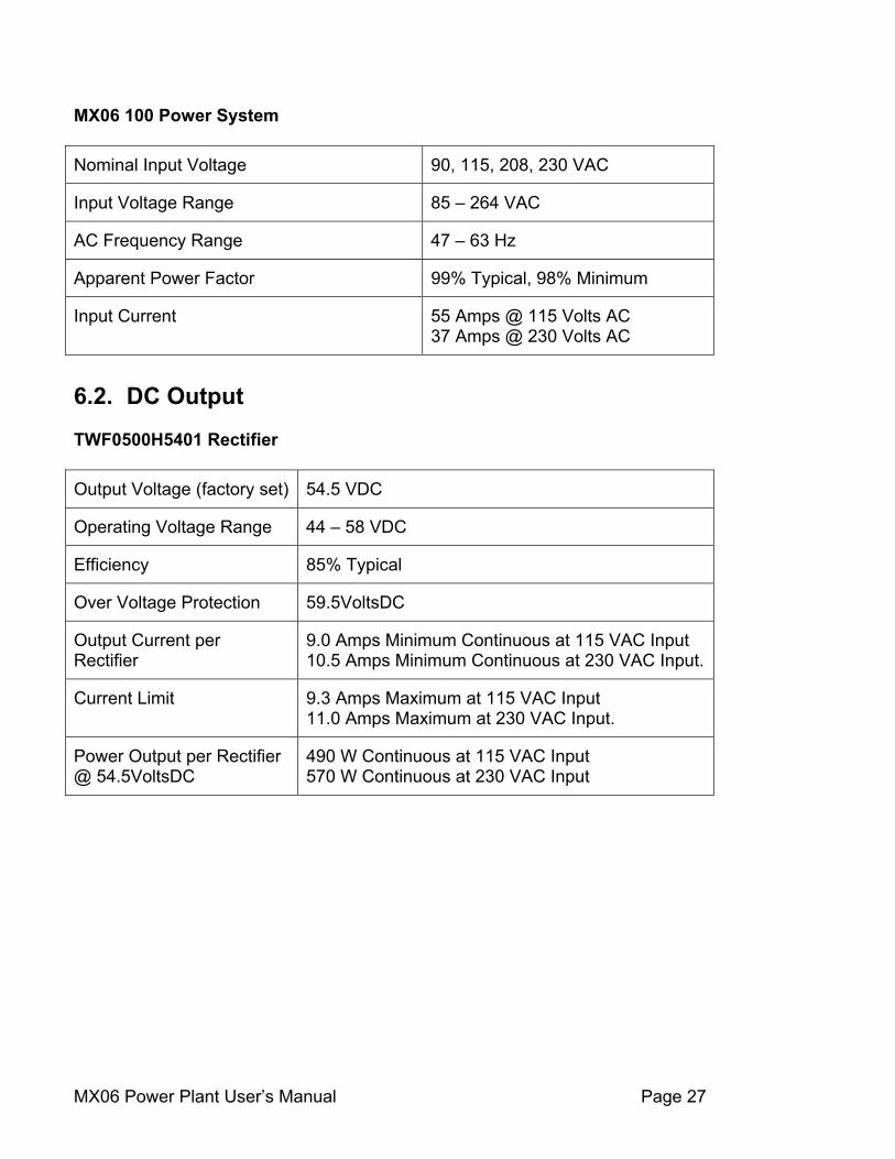
MX06 100 Power System Nominal Input Voltage 90, 115, 208, 230 VAC
Input Voltage Range 85 – 264 VAC
AC Frequency Range 47 – 63 Hz
Apparent Power Factor 99% Typical, 98% Minimum
Input Current 55 Amps @ 115 Volts AC 37 Amps @ 230 Volts AC
6.2. DC Output TWF0500H5401 Rectifier Output Voltage (factory set) 54.5 VDC
Operating Voltage Range 44 – 58 VDC
Efficiency 85% Typical
Over Voltage Protection 59.5VoltsDC
Output Current per Rectifier
9.0 Amps Minimum Continuous at 115 VAC Input 10.5 Amps Minimum Continuous at 230 VAC Input.
Current Limit 9.3 Amps Maximum at 115 VAC Input 11.0 Amps Maximum at 230 VAC Input.
Power Output per Rectifier @ 54.5VoltsDC
490 W Continuous at 115 VAC Input 570 W Continuous at 230 VAC Input
MX06 Power Plant User’s Manual Page 28
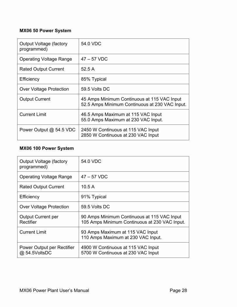
MX06 50 Power System Output Voltage (factory programmed)
54.0 VDC
Operating Voltage Range 47 – 57 VDC
Rated Output Current 52.5 A
Efficiency 85% Typical
Over Voltage Protection 59.5 Volts DC
Output Current 45 Amps Minimum Continuous at 115 VAC Input 52.5 Amps Minimum Continuous at 230 VAC Input.
Current Limit 46.5 Amps Maximum at 115 VAC Input 55.0 Amps Maximum at 230 VAC Input.
Power Output @ 54.5 VDC 2450 W Continuous at 115 VAC Input 2850 W Continuous at 230 VAC Input
MX06 100 Power System Output Voltage (factory programmed)
54.0 VDC
Operating Voltage Range 47 – 57 VDC
Rated Output Current 10.5 A
Efficiency 91% Typical
Over Voltage Protection 59.5 Volts DC
Output Current per Rectifier
90 Amps Minimum Continuous at 115 VAC Input 105 Amps Minimum Continuous at 230 VAC Input.
Current Limit 93 Amps Maximum at 115 VAC Input 110 Amps Maximum at 230 VAC Input.
Power Output per Rectifier @ 54.5VoltsDC
4900 W Continuous at 115 VAC Input 5700 W Continuous at 230 VAC Input
MX06 Power Plant User’s Manual Page 29
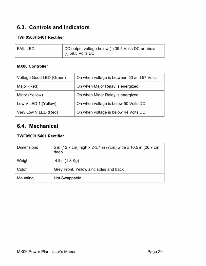
6.3. Controls and Indicators TWF0500H5401 Rectifier FAIL LED DC output voltage below (-) 39.5 Volts DC or above
(-) 59.5 Volts DC.
MX06 Controller Voltage Good LED (Green) On when voltage is between 50 and 57 Volts.
Major (Red) On when Major Relay is energized
Minor (Yellow) On when Minor Relay is energized
Low V LED 1 (Yellow) On when voltage is below 50 Volts DC.
Very Low V LED (Red) On when voltage is below 44 Volts DC.
6.4. Mechanical TWF0500H5401 Rectifier Dimensions 5 in (12.7 cm) high x 2-3/4 in (7cm) wide x 10.5 in (26.7 cm
deep
Weight 4 lbs (1.8 Kg)
Color Grey Front, Yellow zinc sides and back
Mounting Hot Swappable
MX06 Power Plant User’s Manual Page 30
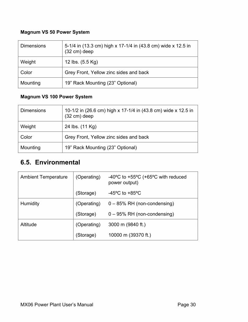
Magnum VS 50 Power System Dimensions 5-1/4 in (13.3 cm) high x 17-1/4 in (43.8 cm) wide x 12.5 in
(32 cm) deep
Weight 12 lbs. (5.5 Kg)
Color Grey Front, Yellow zinc sides and back
Mounting 19” Rack Mounting (23” Optional) Magnum VS 100 Power System Dimensions 10-1/2 in (26.6 cm) high x 17-1/4 in (43.8 cm) wide x 12.5 in
(32 cm) deep
Weight 24 lbs. (11 Kg)
Color Grey Front, Yellow zinc sides and back
Mounting 19” Rack Mounting (23” Optional) 6.5. Environmental
(Operating) -40ºC to +55ºC (+65ºC with reduced power output)
Ambient Temperature
(Storage) -45ºC to +85ºC
(Operating) 0 – 85% RH (non-condensing) Humidity
(Storage) 0 – 95% RH (non-condensing)
(Operating) 3000 m (9840 ft.) Altitude
(Storage) 10000 m (39370 ft.)
MX06 Power Plant User’s Manual Page 31
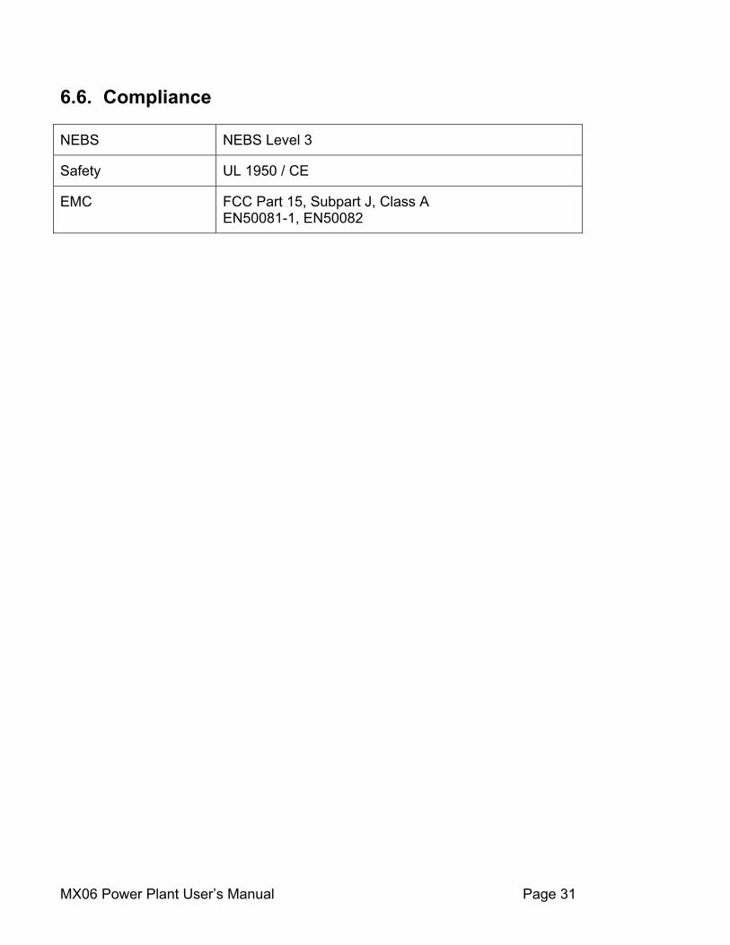
6.6. Compliance NEBS NEBS Level 3
Safety UL 1950 / CE
EMC FCC Part 15, Subpart J, Class A EN50081-1, EN50082
MX06 Power Plant User’s Manual Page 32
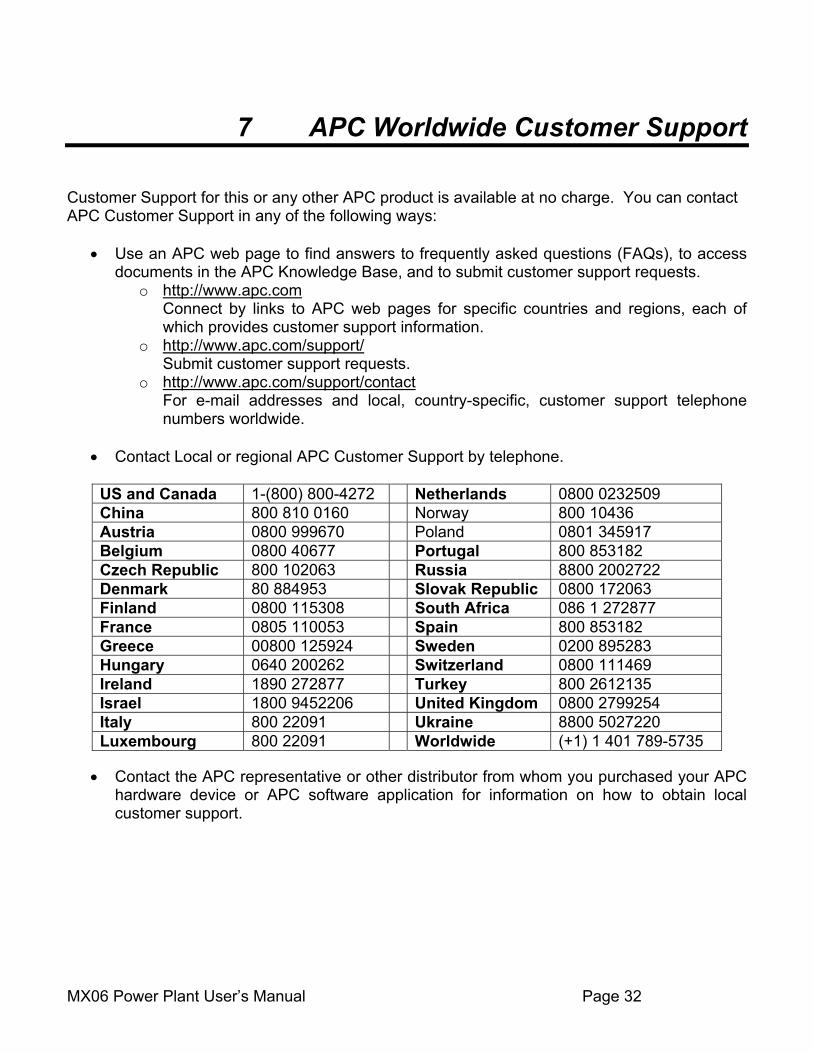
7 APC Worldwide Customer Support Customer Support for this or any other APC product is available at no charge. You can contact APC Customer Support in any of the following ways:
• Use an APC web page to find answers to frequently asked questions (FAQs), to access documents in the APC Knowledge Base, and to submit customer support requests.
o http://www.apc.com Connect by links to APC web pages for specific countries and regions, each of which provides customer support information.
o http://www.apc.com/support/ Submit customer support requests.
o http://www.apc.com/support/contact For e-mail addresses and local, country-specific, customer support telephone numbers worldwide.
• Contact Local or regional APC Customer Support by telephone.
US and Canada 1-(800) 800-4272 Netherlands 0800 0232509 China 800 810 0160 Norway 800 10436 Austria 0800 999670 Poland 0801 345917 Belgium 0800 40677 Portugal 800 853182 Czech Republic 800 102063 Russia 8800 2002722 Denmark 80 884953 Slovak Republic 0800 172063 Finland 0800 115308 South Africa 086 1 272877 France 0805 110053 Spain 800 853182 Greece 00800 125924 Sweden 0200 895283 Hungary 0640 200262 Switzerland 0800 111469 Ireland 1890 272877 Turkey 800 2612135 Israel 1800 9452206 United Kingdom 0800 2799254 Italy 800 22091 Ukraine 8800 5027220 Luxembourg 800 22091 Worldwide (+1) 1 401 789-5735
• Contact the APC representative or other distributor from whom you purchased your APC
hardware device or APC software application for information on how to obtain local customer support.

MX06 Power Plant User’s Manual Page 33
8 Limited Product Warranty The limited warranty provided by American Power Conversion Corporation ("APC") in this Statement of Limited Factory Warranty applies only to Products Buyer purchases for your commercial or industrial use in the ordinary course of Buyer's business. APC PRODUCTS COVERED ("Product or Products"): MX06 50 MX06 100 Terms of Warranty: APC warrants that the Product shall be free from defects in materials and workmanship, for a period of two (2) years from the date of shipment. Warranty Procedure If initial physical inspection results in identification of a material or workmanship flaw(s) that could impair Product performance as defined by APC’s electrical and physical specification in effect at the time of shipment, and if this flaw(s) is not due to transportation damage or installation abuse, contact APC or call the 24-hour emergency number, (800) 800 4APC, to request assistance. You will be provided either a) an RMA number with instructions for return of the equipment or component(s) to the APC factory service center, FOB destination, freight pre-paid, for examination, or b) for non-returnable systems and equipment, notice to wait until an APC authorized service representative arrives at the site to inspect the equipment. Repaired or advance replacement modules or circuit components will normally be available within 24 to 48 hours of receipt of equipment or RMA. Warranty Obligations - Repair or Replacement If, during the warranty period, the Product is found to be physically or electrically faulty due to defective materials or workmanship, the defective Product(s) or component(s) will be repaired or replaced at the sole option of APC. If the procedure outlined above for contacting APC immediately after identifying a material or workmanship flaw(s) that could impair Product performance has been properly followed, such repair or replacement of Product(s) or component(s) shall include all charges for replacement materials or repair labor. Costs incurred for replacement installation including, but not limited to, installation equipment, travel expenses of an APC representative(s), and costs of installation material transportation expenses are not included as a part of this warranty. Any replacement components or materials furnished under this warranty may be new or factory remanufactured. THIS WARRANTY DOES NOT COVER CONSUMABLES OR PREVENTATIVE MAINTENANCE ITEMS. REPAIR OR REPLACEMENT OF A DEFECTIVE PRODUCT OR COMPONENT THEREOF DOES NOT EXTEND THE ORIGINAL WARRANTY PERIOD.
Exclusions and Limitations This Warranty is extended to the first person, firm, association or corporation for whom the APC Product specified herein has been bought. This Warranty is not transferable or assignable without the prior written permission of APC. This limited warranty does not cover damage due to external causes, including accident, abuse, misuse, servicing not authorized by APC, usage not in accordance with Product instructions, failure to perform preventative maintenance, and problems cause by use of parts and components not supplied by APC. This limited warranty does not apply to Products from which the serial numbers have been removed, or to conditions resulting from improper use, accidents, external causes, including installation, relocation of hardware, service or modifications not performed by APC or its authorized service providers, or operation outside the environmental parameters specified for the Product. APC does not warrant that the operation of any Product will be uninterrupted or error free. Warranty service may not be performed if APC or other suppliers reasonably believe conditions at the Buyer's site represent a safety or health risk. THERE ARE NO WARRANTIES, EXPRESS OR IMPLIED, BY OPERATION OF LAW OR OTHERWISE, OF PRODUCTS SOLD, SERVICED OR FURNISHED UNDER THIS AGREEMENT OR IN CONNECTION HEREWITH. APC DISCLAIMS ALL IMPLIED WARRANTIES OF MERCHANTABILITY, SATISFACTION AND FITNESS FOR A PARTICULAR PURPOSE. APC’S EXPRESS WARRANTIES WILL NOT BE ENLARGED, DIMINISHED, OR AFFECTED BY AND NO OBLIGATION OR LIABILITY WILL ARISE OUT OF, APC’S RENDERING OF TECHNICAL OR OTHER ADVICE OR SERVICE IN CONNECTION WITH THE PRODUCTS. THE FOREGOING WARRANTIES AND REMEDIES ARE EXCLUSIVE AND IN LIEU OF ALL OTHER WARRANTIES AND REMEDIES. THE WARRANTIES SET FORTH ABOVE, CONSTITUTE APC’S SOLE LIABILITY AND YOUR EXCLUSIVE REMEDY FOR ANY BREACH OF SUCH WARRANTIES. APC’S WARRANTIES RUN ONLY TO YOU AND ARE NOT EXTENDED TO ANY THIRD PARTIES. IN NO EVENT SHALL APC, ITS OFFICERS, DIRECTORS, AFFILIATES OR EMPLOYEES BE LIABLE FOR ANY FORM OF INDIRECT, SPECIAL, CONSEQUENTIAL OR PUNITIVE DAMAGES, ARISING OUT OF THE USE, SERVICE OR INSTALLATION, OF THE PRODUCTS, WHETHER SUCH DAMAGES ARISE IN CONTRACT OR TORT, IRRESPECTIVE OF FAULT, NEGLIGENCE OR STRICT LIABILITY OR WHETHER APC HAS BEEN ADVISED IN ADVANCE OF THE POSSIBILITY OF SUCH DAMAGES.