Embed Size (px)
Citation preview

Page 1 of 36
INSTRUCTION MANUAL
MX06 - MX100 OVAL GEAR FLOWMETER SERIES
MXL-INST
Rev 7
04/2016
To the Owner
Please read and retain this instruction manual to assist you in the operation and maintenance of this product. This manual contains connection and operating in-structions for the MX series Flow Meters with Pulse outputs. Models with a Liquid Crystal Display have an addi-tional LCD instruction manual supplied. If you need further assistance, contact your local representative or distributor for advice. This Flow Meter has incorporated the oval gear prin-cipal into its design. This is proven to be a reliable and highly accurate method of measuring flow. Exceptional repeatability and high accuracy over a wide range of fluid viscosities and flow rates are features of the oval gear design. With a low pressure drop and high pressure rating oval gear flow meters are suitable for both gravity and (in-line) pump applications.
Macnaught offer a comprehensive set web based support materials to compliment this instruction manual. Access the website by scanning the QR code below.
WWW.MACNAUGHT.COM.AU

Page 2 of 36
index
Installation
Pre-installation checks Page 3 ………………………………………………………….
Operating Principle Page 3 ………………………………………………………….
Installation Procedure Page 3 ………………………………………………………….
Maintenance Procedure
Disassembly Page 4 ………………………………………………………….
Reassembly Page 4 ………………………………………………………….
Flowmeter Specifications
Flowmeter Specifications Page 5-8 ………………………………………………………….
Wiring Diagram - Standard Pulser Page 9 ………………………………………………………….
Wiring Diagram - PCB sensor Page 10 ………………………………………………………….
Service
Troubleshooting Guide Page 12 ………………………………………………………….
Exploded Diagrams Page 13-14 ………………………………………………………….
Spare Parts Kits Page 15-17 ………………………………………………………….
Wetted Parts Page 18-21 ………………………………………………………….
General
Pressure Drop Graphs Page 22 ………………………………………………………….
Dimensional Diagrams Page 23-31 ………………………………………………………….
Wiring Diagram - High Temp Sensor (-HT) Page 11 ……………………………………………
Meter Cap Torques Page 15 ………………………………………………………….
Page 3 of 36
IMPORTANT INFORMATION
OPERATING PRINCIPLE
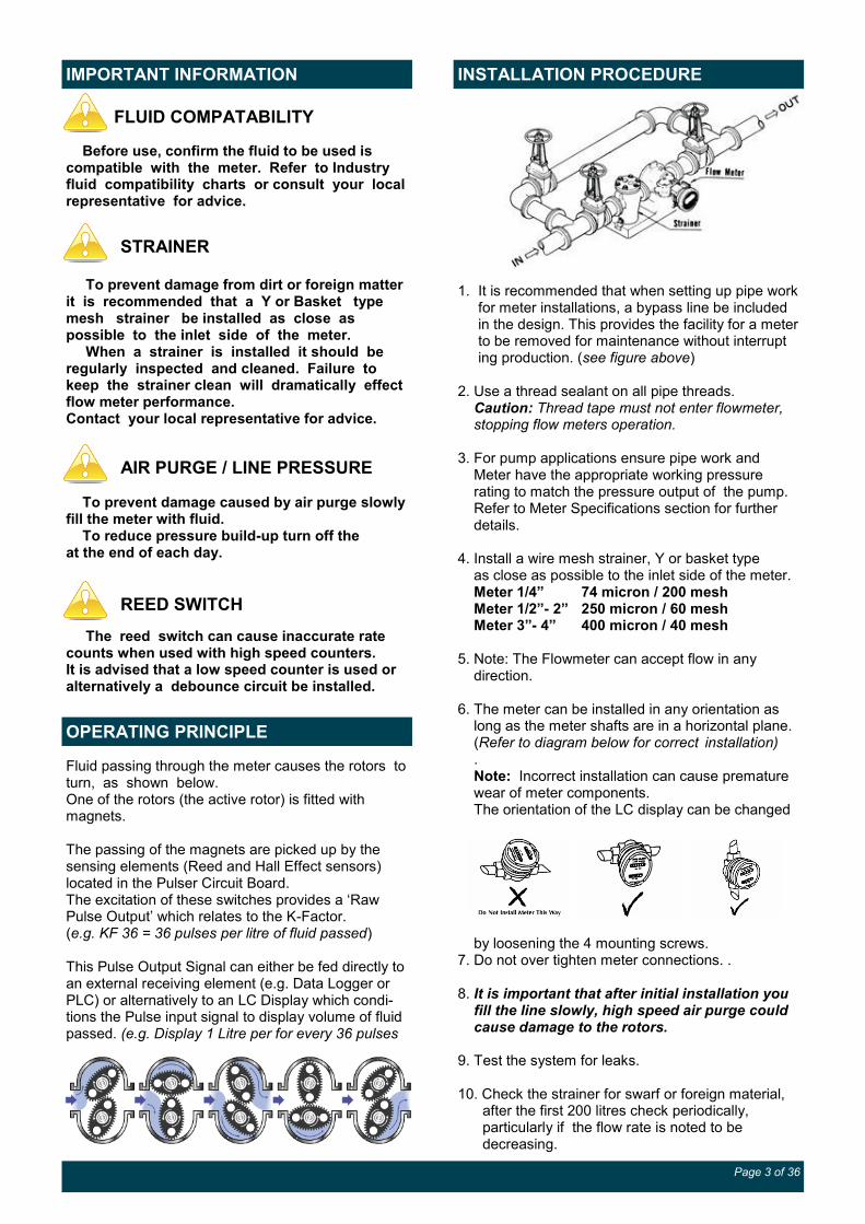
INSTALLATION PROCEDURE
FLUID COMPATABILITY
Before use, confirm the fluid to be used is compatible with the meter. Refer to Industry fluid compatibility charts or consult your local representative for advice.
To prevent damage from dirt or foreign matter it is recommended that a Y or Basket type mesh strainer be installed as close as possible to the inlet side of the meter. When a strainer is installed it should be regularly inspected and cleaned. Failure to keep the strainer clean will dramatically effect flow meter performance. Contact your local representative for advice.
To prevent damage caused by air purge slowly fill the meter with fluid. To reduce pressure build-up turn off the at the end of each day.
The reed switch can cause inaccurate rate counts when used with high speed counters. It is advised that a low speed counter is used or alternatively a debounce circuit be installed.
AIR PURGE / LINE PRESSURE
STRAINER
Fluid passing through the meter causes the rotors to turn, as shown below. One of the rotors (the active rotor) is fitted with magnets. The passing of the magnets are picked up by the sensing elements (Reed and Hall Effect sensors) located in the Pulser Circuit Board. The excitation of these switches provides a ‘Raw Pulse Output’ which relates to the K-Factor. (e.g. KF 36 = 36 pulses per litre of fluid passed) This Pulse Output Signal can either be fed directly to an external receiving element (e.g. Data Logger or PLC) or alternatively to an LC Display which condi-tions the Pulse input signal to display volume of fluid passed. (e.g. Display 1 Litre per for every 36 pulses
1. It is recommended that when setting up pipe work for meter installations, a bypass line be included in the design. This provides the facility for a meter to be removed for maintenance without interrupt ing production. (see figure above) 2. Use a thread sealant on all pipe threads. Caution: Thread tape must not enter flowmeter, stopping flow meters operation. 3. For pump applications ensure pipe work and Meter have the appropriate working pressure rating to match the pressure output of the pump. Refer to Meter Specifications section for further details. 4. Install a wire mesh strainer, Y or basket type as close as possible to the inlet side of the meter. Meter 1/4” 74 micron / 200 mesh Meter 1/2”- 2” 250 micron / 60 mesh Meter 3”- 4” 400 micron / 40 mesh 5. Note: The Flowmeter can accept flow in any direction. 6. The meter can be installed in any orientation as long as the meter shafts are in a horizontal plane. (Refer to diagram below for correct installation) . Note: Incorrect installation can cause premature wear of meter components. The orientation of the LC display can be changed
by loosening the 4 mounting screws. 7. Do not over tighten meter connections. . 8. It is important that after initial installation you fill the line slowly, high speed air purge could cause damage to the rotors. 9. Test the system for leaks. 10. Check the strainer for swarf or foreign material, after the first 200 litres check periodically, particularly if the flow rate is noted to be decreasing.
REED SWITCH

Page 4 of 36
MAINTENANCE PROCEDURE
Note: Maintenance can be carried out to the liquid crystal displays and pulse output modules without having to remove or isolate the meter from the pro-cess line. When maintenance to any other part of the meter is required, the meter must be isolated and the line pressure released. Refer to the exploded parts diagram on (see Fig for item numbers. Note: It is advisable to mark all components with a marker pen before disassembly, to ensure all the components are replaced to their correct position during the reassembly process. 1. Remove the meter cap by loosening the bolts on the underside of the meter body. (see FIG 1) 2. Remove the O-Ring from the O-Ring groove in the meter cap. Wipe clean of grease and store in clean place 3. Remove rotors from the meter body 4. Remove the shafts from the meter body.
DISASSEMBLY
REASSEMBLY
1. Before reassembling check the condition of the rotors (replace if necessary). 2. Replace the shafts into the meter body. 3. There are two Rotor Types. Active and Neutral. The Active Rotor is fitted with the magnets. They can be identified by running a metal object over the face of the rotor (smooth side) Caution: The active rotor is always fitted nearest ‘dimple’ on the meter body (see FIG 3) Replace Active Rotor. Check the smooth side of the rotor is the leading face when fitting onto the shaft and into the meter body. (see Fig 2). Replace Neutral Rotor. Check that the smooth side of the rotor is the leading face when fitting onto the shaft. (see FIG 2) Fit the neutral rotor onto the shafts ensuring that the rotor pair are at 90 degrees to one another. (see FIG 3) Check their operation by turning either of the rotors. If the rotors are not in mesh correctly, or do not move freely, remove one of the rotors and replace correctly at 90 degrees to one another.
4. Smear the O-Ring with a light film of grease. Replace the O-Ring into groove in the meter cap. The O-Ring will need to be replaced if it has grown or is damaged in anyway. 5. Replace the meter cap. 6. Insert the cap head screws and tighten in a diagonal sequence 1, 5, 7, 3, etc. (see Meter Torque Ratings, page 15) 7. Test the meter by turning the rotors with a finger or by applying very low air pressure (no more than a good breath) to one end of the meter, before returning the meter to service.
Rotor Face
Smooth side
FIG 2
FIG 1
FIG 3 Dimple
Active Rotor

Page 5 of 36
FLOWMETER SPECIFICATIONS
series MX06 Metric US
Flow Range Below 5 cP 2 to 100 LPH 0.5 to 26 GPH
5 to 1000 cP 0.5 to 100 LPH 0.13 to 26.4 GPH
K-Factor (Sensor Pulses per Unit of Measure) Refer to Flowmeter Data Plate
Max Temperature (model MX06F) -20°C - 80°C -4°F - 176°F
(models MX06S) -40°C - 120°C -40°F - 248°F
(models MX06P) -40°C - 150°C -40°F - 302°F
Maximum Operating Pressure1 6895 kPa 1000 psi
Accuracy of Reading ±0.5% (0.25% available with reduced range)
1. Conforms to Directive 97/23/EC—Cat 1
series MX09 Metric US
Flow Range Below 5 cP 25 to 500 LPH 6.6 to 132 GPH
5 to 1000 cP 15 to 500 LPH 4 to 132 GPH
K-Factor (Sensor Pulses per Unit of Measure) Refer to Flowmeter Data Plate
Max Temperature (model MX09F) -20°C - 80°C -4°F - 176°F
(models MX09S) -40°C - 120°C -40°F - 248°F
(models MX09P) -40°C - 150°C -40°F - 302°F
Maximum Operating Pressure1 6895 kPa 1000 psi
Accuracy of Reading ±0.5% (0.25% available with reduced range)
1. Conforms to Directive 97/23/EC—Cat 1
series MX12 Metric US
Flow Range Below 5 cP 3 to 25 LPM 0.8 to 6.6 GPM
5 to 1000 cP 2 to 30 LPM 0.5 to 8 GPM
K-Factor (Sensor Pulses per Unit of Measure) Refer to Flowmeter Data Plate
Max Temperature (model MX12F) -20°C - 80°C -4°F - 176°F
(models MX12S) -40°C - 120°C -40°F - 248°F
(models MX12P) -40°C - 150°C -40°F - 302°F
Maximum Operating Pressure1 13790 kPa 2000 psi
Accuracy of Reading ±0.5% (0.25% available with reduced range)
1. Conforms to Directive 97/23/EC—Cat 1

Page 6 of 36
FLOWMETER SPECIFICATIONS
series MX19 Metric US
Flow Range Below 5 cP 8 to 70 LPM 2 to 18.5 GPM
5 to 1000 cP 3 to 80 LPM 0.8 to 21 GPM
K-Factor (Sensor Pulses per Unit of Measure) Refer to Flowmeter Data Plate
Max Temperature (model MX19F) -20°C - 80°C -4°F - 176°F
(model MX19S) -40°C - 120°C -40°F - 248°F
(models MX19P) -40°C - 150°C -40°F - 302°F
Maximum Operating Pressure1 13790 kPa 2000 psi
Accuracy of Reading ±0.5% (0.25% available with reduced range)
1. Conforms to Directive 97/23/EC—Cat 1
series MX25 Metric US
Flow Range Below 5 cP 10 to 100 LPM 2.6 to 26 GPM
5 to 1000 cP 6 to 120 LPM 1.6 to 32 GPM
K-Factor (Sensor Pulses per Unit of Measure) Refer to Flowmeter Data Plate
Max Temperature (model MX25F) -20°C - 80°C -4°F - 176°F
(model MX25S) -40°C - 120°C -40°F - 248°F
(models MX25P) -40°C - 150°C -40°F - 302°F
Maximum Operating Pressure1 13790 kPa 2000 psi
Accuracy of Reading ±0.5% (0.25% available with reduced range)
1. Conforms to Directive 97/23/EC—Cat 1
series MX40 Metric US
Flow Range Below 5 cP 15 to 235 LPM 4 to 62 GPM
5 to 1000 cP 10 to 250 LPM 2.6 to 66 GPM
K-Factor (Sensor Pulses per Unit of Measure) Refer to Flowmeter Data Plate
Max Temperature (model MX40F) -20°C - 80°C -4°F - 176°F
(model MX40S) -40°C - 120°C -40°F - 248°F
(models MX40P) -40°C - 150°C -40°F - 302°F
Maximum Operating Pressure1 10342 kPa 1500 psi
Accuracy of Reading ±0.5% (0.25% available with reduced range)
1. Conforms to Directive 97/23/EC—Cat 1

Page 7 of 36
FLOWMETER SPECIFICATIONS
series MX50 Metric US
Flow Range Below 5 cP 15 to 500 LPM 4 to 130 GPM
5 to 1000 cP 15 to 500 LPM 4 to 130 GPM
K-Factor (Sensor Pulses per Unit of Measure) 6.7 pulses/L 25.36 pulses/G
Max Temperature (model MX50F) -20°C - 80°C -4°F - 176°F
(models MX50S) -40°C - 120°C -40°F - 248°F
(models MX50P) -40°C - 150°C -40°F - 302°F
Maximum Operating Pressure1 8274 kPa 1200 psi
Accuracy of Reading ±0.5% (0.25% available with reduced range)
1. Conforms to Directive 97/23/EC—Cat 1
series MX75 Metric US
Flow Range Below 5 cP 60 to 600 LPM 17 to 170 GPM
5 to 1000 cP 20 to 733 LPM 5 to 194 GPM
K-Factor (Sensor Pulses per Unit of Measure) Refer to Flowmeter Data Plate
Max Temperature (model MX75F ) -20°C - 120°C -4°F - 248°F
(model MX75S) -40°C - 120°C -40°C - 248°F
(models MX75P) -40°C - 150°C -40°F - 302°F
Maximum Operating Pressure1 1200 kPa 175 psi
Accuracy of Reading ±0.5% (0.25% available with reduced range)
1. Conforms to Directive 97/23/EC—Cat 1
series MX100 Metric US
Flow Range Below 5 cP 220 to 1000 LPM 60 to 250 GPM
5 to 1000 cP 120 to 1200 LPM 30 to 300 GPM
K-Factor (Sensor Pulses per Unit of Measure) Refer to Flowmeter Data Plate
Max Temperature (model MX100F ) -20°C - 120°C -4°F - 248°F
(model MX100S) -40°C - 120°C -40°C - 248°F
Maximum Operating Pressure1 1200 kPa 175 psi
Accuracy of Reading ±0.5% (0.25% available with reduced range)
1. Conforms to Directive 97/23/EC—Cat 1

Page 8 of 36
FLOWMETER SPECIFICATIONS
High Viscosity Applications
Ensure the Flowmeter is fitted with ‘High Viscosity Rotors’ if the fluid being metered is 1000 cP or above
High Viscosity Rotors For Fluids above 1000 Centipoise (cP)
DIGITAL DISPLAYS
The MX Flow meter series is supplied with either a Compact Pulser and Digital Display option. Please note the wiring diagrams in the following pages are for the Compact Pulser Output Modules and the PCB (Sensor Board), which is responsible for providing a Raw Pulse input to the LC display If the Flow meter is supplied with an LC Display fitted, please consult the appropriate Instruction Manual, as advised below, for all programming and wiring instructions.
Analogue Output (4-20mA)
Analogue outputs are available as an auxiliary display signal by including either of the following LC displays with
your flowmeter. These may be fitted to the meter or remote (wall mount) types.
Output Type E PRA 12mm LC Display with analogue output module
Output Type G ERA 17mm LC Display with analogue output module
Output option: type ‘D’ type ’E’ type ‘F” type “G’ type “H” Display Type : PR PRA ER ERA ERB ERS (remote mount only) Display Part Number: MXD-DS MXD-ES MXD-ES MXD-GS MXD-HS ERS-RMP / ERS-RMA Instruction Sheet: DR013 DR014 MS574 MS392 MS476 MS351

Page 9 of 36
WIRING DIAGRAM 1 PCB Output type A,D,E,F,G,H
Pulser Specifications
Output Signals Standard Pulse Meter 2x Digital (Square Wave)
Reed Switch (Mechanical Sensor)
Current Maximum 500mA
Voltage Maximum 30V DC
Contact Rating Maximum1 10W
Hall Effect IC (Electronic Sensor)
Maximum Supply Current 7.5mA
Maximum Output Current 25mA
Operating Voltage 4.5V to 24V DC
Transistor Type Open-Collector NPN
1. Contact rating maximum is 10W. Neither current nor voltage maximums should be exceeded in achieving this.

Page 10 of 36
Reed Switch To maximise the life of the reed switch contacts, the pulse board comes equipped with a 1k8Ω current limiting resistor in series with the reed switch as standard. These resistors are user swappable should you require a different value for your system.
WIRING DIAGRAM 1 PCB Output types A,D,E,F,G,H
NPN Open Collector Hall Effect Sensor
The output for the hall effect sensor is NPN (current sinking, open collector). For correct operation, it is advisable to have a pull-up resistor installed. The hall effect sensor is equipped with a 1k8Ω pull-up resistor between signal and supply as standard. This in-built pull-up resistor can be bypassed by moving the jumper pin to the off position if required. A pull-up resistor of your choosing can be installed between signal and supply, provided the in-built pull-up resistor be by-passed first.
Note:
Local Display is
connected to Reed 1
White
Yellow
Red
Black
Green
Screening
cable
PCB with Terminal Block
PCB with Soldered Wire

Page 11 of 36
WIRING DIAGRAM 3 High Temperature Output type ‘T’
Pulser Specifications
SENSOR TYPE OMNI POLAR NPN
SPECIFICATIONS
Construction Stainless Steel Housing
Operating Voltage 4.5 to 30V DC
Maximum Supply Current 18mA
-40 - 150°C
Temperature Range
-40 - 302°F
Page 12 of 36
TROUBLESHOOTING GUIDE
Problem Cause Remedy
Fluid will not flow through meter
a) Foreign matter blocking rotors b) Line strainer blocked c) Damaged rotors d) Meter connections over tightened e) Fluid is too viscous
a) Dismantle meter, clean rotors (strainer must be fitted in line) b) Clean strainer c) Replace rotors (Strainer must be fitted in line) d) Re-adjust connections e) See specifications for maximum viscosity
Reduced flow through meter
a) Strainer is partially blocked b) Fluid is too viscous
a) Clean strainer b) See specifications for maximum viscosity
Meter reading inaccurate
a) Fluid flow rate is too high or too low b) Air in fluid c) Excess wear caused by incorrect instal-lation
a) See specifications for minimum and maximum flow rates b) Bleed air from system c) Check meter body and rotors. Replace as required. Refer to installation instructions
Meter not giving a pulse signal
a) Faulty hall effect sensor b) Faulty reed switch c) Magnets failed
a) Replace PCB Board b) Replace PCB Board c) Replace magnets
LCD register not working
a) Battery not connected properly b) Battery flat c) Faulty wiring connections d) Faulty LC Display e) Faulty connection from LC Display
a) Check battery connections b) Replace battery c) Check wiring for loose or faulty connections d) Replace LC Display e) Check wiring connections
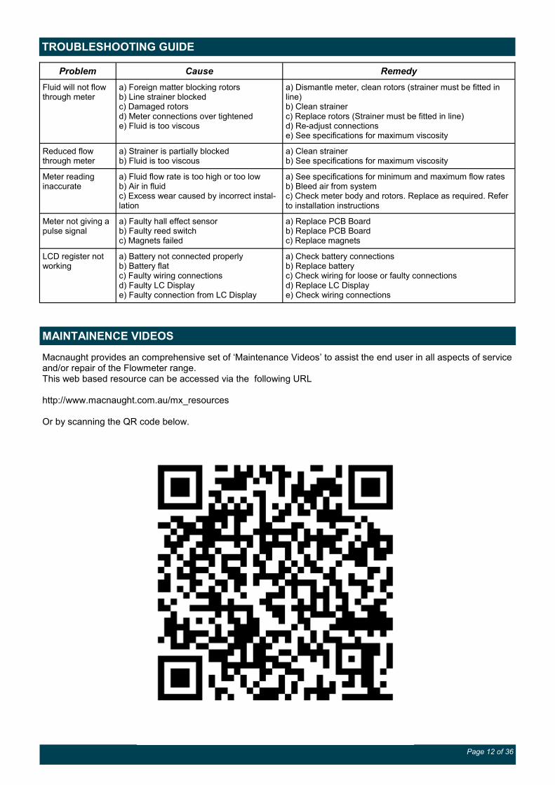
MAINTAINENCE VIDEOS
Macnaught provides an comprehensive set of ‘Maintenance Videos’ to assist the end user in all aspects of service and/or repair of the Flowmeter range. This web based resource can be accessed via the following URL http://www.macnaught.com.au/mx_resources Or by scanning the QR code below.

Page 13 of 36
EXPLODED DIAGRAM models MX06-MX50
PARTS IDENTIFICATION
METER COMPONENTS ITEM NO.
CIRCLIP 1
CAM 2
METER BODY 3
METER CAP O-RING 4
MAGNET HOUSING 5
MAGNETS 6
ROTORS 7
ROTOR SHAFTS 8
METER CAP 9
METER CAP SCREWS 10

Page 14 of 36
PARTS IDENTIFICATION
PART DESCRIPTION Item No.
Meter Body 1
Rotor Shafts 2
Rotors 3
Meter Cap O-Ring 4
Meter Cap 5
Cam 6
Circlip 7
Meter Cap Bolts 8
Flange Seals 9
Process Connection (Flanged or Threaded) 10
Flange Washers 11
Flange Bolts 12
EXPLODED DIAGRAM models MX75-MX100

Page 15 of 36
SPARE PARTS KITS
Spare Kit options, for both Flowmeter and Display/Pulser modules, are available as replacement components.
Pulser Kit / LC Display Module - Replacement PCB complete with electronic housing. - LC Display module (Electronic housing not included)
Rotor Kit - Rotor assembly (includes Meter Cap bolts and O-Ring)
Seal Kit - O-Rings/Gaskets (includes Meter Cap Bolts)
Meter Torque Ratings
Series Pressure
(psi) Torque (Nm) Lubrication -
MX06 1000
6.5 Nm Yes MX09 1000
MX12 2000
MX19 2000 15 Nm Yes
MX25 2000
MX40 1500
33 Nm Yes MX50 1200
MX75 175
MX100 175
METER TORQUE
SPARE KITS – DISPLAY AND PULSER MODULE
Output
Type Description Pulser Kit
Display Module
only
Display/Pulser
complete
Type A Standard Pulser MXD-AS
Type D PR Digital Register MXS-PCB-PR MXS-DIS-PR MXD-DS
Type E PRA Digital Register MXS-PCB-PR MXS-DIS-PRA MXD-ES
Type F ER Digital Register MXS-PCB-ER MXS-DIS-ER MXD-FS
Type G ERA Digital Register MXS-PCB-ER MXS-DIS-ERA MXD-GS
Type H ERB Batch Controller MXS-PCB-ER MXS-DIS-ERB MXD-HS
Type T High Temperature MXD-TS

Page 16 of 36
SPARE PARTS KITS
spare kits Series MX06 MX06F MX06S MX06P
Standard MXS06F-rotor MXS06S-rotor MXS06P-rotor
ROTOR KIT
High Temp MXS06P-HTrotor
SEAL KIT MXS06F-seal MXS06S-seal MXS06P-seal
spare kits Series MX09 MX09F MX09S MX09P
Standard MXS09F-rotor MXS09S-rotor MXS09P-rotor
ROTOR KIT High Viscosity MXS09S-HVrotor MXS09P-HVrotor
High Temp MXS09P-HTrotor
SEAL KIT MXS09F-seal MXS09S-seal MXS09P-seal
spare kits Series MX12 MX12F MX12S MX12P
Standard MXS12F-rotor MXS12S-rotor MXS12P-rotor
ROTOR KIT High Viscosity MXS12S-HVrotor MXS12P-HVrotor
High Temp MXS12P-HTrotor
SEAL KIT MXS12F-seal MXS12S-seal MXS12P-seal
spare kits Series MX19 MX19F MX19S MX19P
Standard MXS19F-rotor MXS19S-rotor MXS19P-rotor
ROTOR KIT High Viscosity MXS19S-HVrotor MXS19P-HVrotor
High Temp MXS19P-HTrotor
SEAL KIT MXS19F-seal MXS19S-seal MXS19P-seal
spare kits Series MX25 MX25F MX25S MX25P
Standard MXS25F-rotor MXS25S-rotor MXS25P-rotor
ROTOR KIT High Viscosity MXS25S-HVrotor MXS25P-HVrotor
High Temp MXS25P-HTrotor
SEAL KIT MXS25F-seal MXS25S-seal MXS25P-seal

Page 17 of 36
SPARE PARTS KITS
spare kits Series MX40 MX40F MX40S MX40P
Standard MXS40F-rotor MXS40S-rotor MXS40P-rotor
ROTOR KIT High Viscosity MXS40S-HVrotor MXS40P-HVrotor
High Temp MXS40P-HTrotor
SEAL KIT MXS40F-seal MXS40S-seal MXS40P-seal
spare kits Series MX50 MX50F MX50S MX50P
Standard MXS50F-rotor MXS50S-rotor MXS50P-rotor
ROTOR KIT High Viscosity MXS50S-HVrotor MXS50P-HVrotor
High Temp MXS50P-HTrotor
SEAL KIT MXS50F-seal MXS50S-seal MXS50P-seal
spare kits Series MX75 MX75F MX75S MX75P
Standard MXS75F-rotor MXS75S-rotor MXS75P-rotor
ROTOR KIT High Viscosity MXS75S-HVrotor MXS75P-HVrotor
High Temp MXS75P-HTrotor
SEAL KIT MXS75F-seal MXS75S-seal MXS75P-seal
spare kits Series MX100 MX100F MX100S
ROTOR KIT Standard MXS100F-rotor MXS100S-rotor
MXS100S-HVrotor
SEAL KIT MXS100F-seal MXS100S-seal
Display Register spare kits Display Type
‘D’ ‘E’
Display type
‘F’ ‘G’ ‘H’
BATTERY KIT DR012S MS493S

Page 18 of 36
WETTED PARTS
Wetted parts series MX06 MX06F MX06S MX06P
METER BODY Alum Alum St.St
METER CAP Alum Alum St.St
ROTORS Standard PPS St.St PPS
High Temp St. St
ROTOR SHAFTS St.St St.St St.St
ROTOR BUSHES CA CA
O-RINGS FKM K K
Wetted parts series MX09 MX09F MX09S MX09P
METER BODY Alum Alum St.St
METER CAP Alum Alum St.St
ROTORS Standard PPS St.St PPS
High Viscosity St.St. St.St
High Temp St. St
ROTOR SHAFTS St.St St.St St.St
ROTOR BUSHES CA CA
O-RINGS FKM K K
Wetted parts series MX12 MX12F MX12S MX12P
METER BODY Alum Alum St.St
METER CAP Alum Alum St.St
ROTORS - Standard PPS St.St PPS
High Viscosity St.St. St.St
High Temp St. St
ROTOR SHAFTS St.St St.St St.St
ROTOR BUSHES CA CA
O-RINGS FKM K K

Page 19 of 36
WETTED PARTS
Wetted parts series MX19 MX19F MX19S MX19P
METER BODY Alum Alum St.St
METER CAP Alum Alum St.St
ROTORS - Standard PPS St.St PPS
High Viscosity St.St. St.St
High Temp St. St
ROTOR SHAFTS St.St St.St St.St
ROTOR BUSHES CA CA
O-RINGS FKM K K
Wetted parts series MX25 MX25F MX25S MX25P
METER BODY Alum Alum St.St
METER CAP Alum Alum St.St
ROTORS - Standard PPS St.St PPS
High Viscosity St.St. St.St
High Temp St. St
ROTOR SHAFTS St.St St.St St.St
ROTOR BUSHES CA CA
O-RINGS FKM K K
Wetted parts series MX40 MX40F MX40S MX40P
METER BODY Alum Alum St.St
METER CAP Alum Alum St.St
ROTORS - Standard PPS Alum PPS
High Viscosity Alum St.St
High Temp St. St
ROTOR SHAFTS St.St St.St St.St
ROTOR BUSHES CA CA
O-RINGS FKM K K

Page 20 of 36
WETTED PARTS
Wetted parts series MX50 MX50F MX50S MX50P
METER BODY Alum Alum St.St
METER CAP Alum Alum St.St
ROTORS - Standard PPS Alum PPS
High Viscosity Alum St.St
High Temp St. St
ROTOR SHAFTS St.St St.St St.St
ROTOR BUSHES CA CA
O-RINGS FKM K K
Wetted parts series MX75 MX75F MX75S MX75P
METER BODY Alum Alum St.St
METER CAP Alum Alum St.St
ROTORS - Standard Alum Alum St.St
High Viscosity Alum
ROTOR SHAFTS St.St St.St St.St
ROTOR BUSHES CA CA CA
O-RINGS FKM K K
Wetted parts series MX100 MX100F MX100S
METER BODY Alum Alum
METER CAP Alum Alum
ROTORS - Standard Alum Alum
High Viscosity Alum
ROTOR SHAFTS St.St St.St
ROTOR BUSHES CA CA
O-RINGS FKM K

Page 21 of 36
WETTED PARTS
K - FEP/PTFE Encapsulated
SS - Stainless Steel 316
Al - Aluminium AA610
CA - Carbon
FKM - Viton ®
PPS - Polyphenylene Sulphide (PPS Resin)

Page 22 of 36
PRESSURE DROP v VISCOSITY
100%
50%
25%
10%
5%
100%
50%

Page 23 of 36
DIMENSIONS series MX06-MX50
M
ET
ER
an
d F
LA
NG
E D
IME
NS
ION
S
PU
LS
ER
an
d D
IGIT
AL
DIS
PL
AY
HE
IGH
TS
(d
imen
sion
F)
Mo
del
P
ort
Siz
e
A
B
C
D
E
TY
PE
A
TY
PE
T
TY
PE
D ,
E
TY
PE
F,
G,
H
MX
06
¼”
71
74
- 4
2
25
59
10
4
90
14
3
MX
09
¼”
71
74
- 4
2
25
59
10
4
90
14
3
MX
12
½”
81
87
- 4
9
28
66
11
1
97
15
0
MX
19
¾”
10
0
11
2
- 6
2
37
79
12
4
11
0
16
3
MX
25
1”
10
0
11
2
24
0
75
45
92
13
7
12
3
17
6
MX
40
1 ½
” 1
20
13
7
24
0
10
3
61
12
0
16
5
15
1
20
4
MX
50
2”
14
0
16
3
26
4
12
4
72
14
1
18
6
17
2
22
5
Page 24 of 36
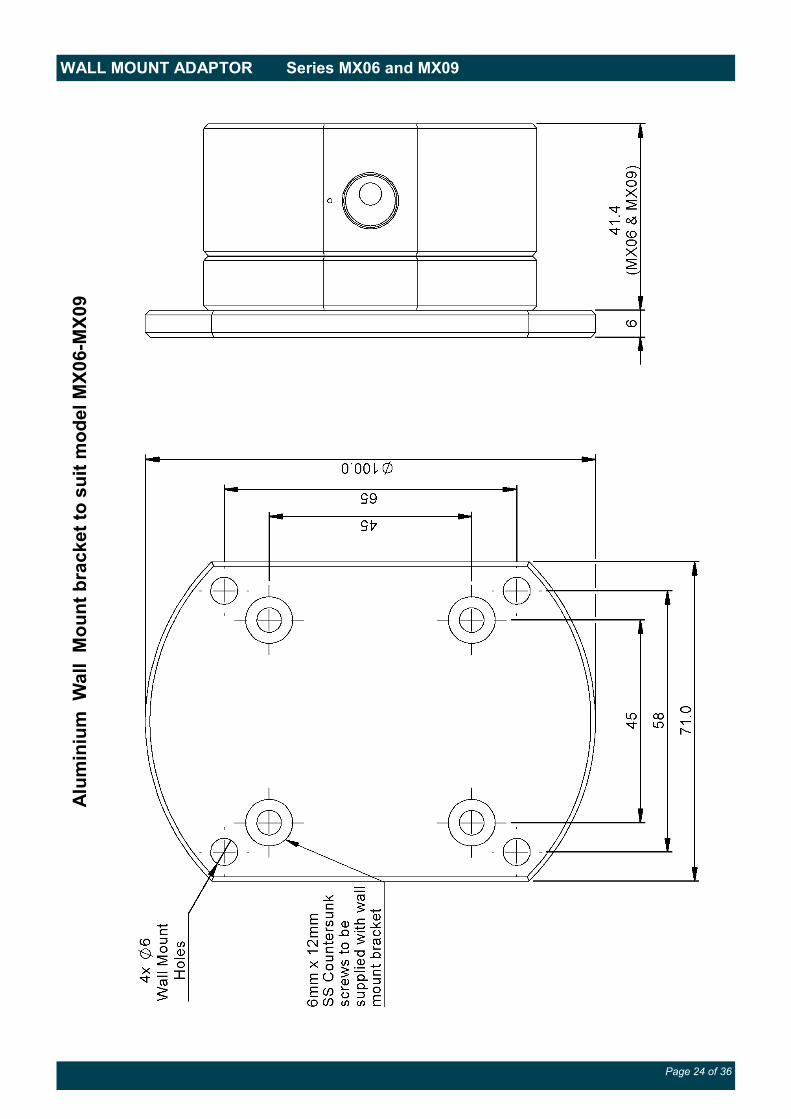
WALL MOUNT ADAPTOR Series MX06 and MX09 A
lum
iniu
m W
all M
ou
nt
bra
ck
et
to s
uit
mo
del M
X0
6-M
X0
9

Page 25 of 36
WALL MOUNT ADAPTOR Series MX12 A
lum
iniu
m W
all M
ou
nt
bra
ck
et
to s
uit
mo
del M
X1
2

Page 26 of 36
WALL MOUNT ADAPTORS Series MX19 A
lum
iniu
m W
all M
ou
nt
bra
ck
et
to s
uit
mo
del M
X1
9

Page 27 of 36
WALL MOUNT ADAPTORS Series MX25 A
lum
iniu
m W
all M
ou
nt
bra
ck
et
to s
uit
mo
del M
X2
5

Page 28 of 36
METER DIMENSIONS series MX75
M
ET
ER
an
d F
LA
NG
E D
IME
NS
ION
S
PU
LS
ER
an
d D
IGIT
AL
DIS
PL
AY
HE
IGH
TS
(dim
ensi
on
F)
Mo
del
F
LA
NG
E
TY
PE
PO
RT
SIZ
E
B
C
D
E
TY
PE
A
TY
PE
T
TY
PE
D ,
E
TY
PE
F,
G,
H
MX
07
5
Alu
min
ium
AN
SI
3”
254
435
179
141
196
241
227
280
DIN
435
JIS
435
Rp
301
NP
T
301
MX
07
5
Sta
inle
ss
Ste
el
AN
SI
344
DIN
340
JIS
340
Rp
256
NP
T
256

Page 29 of 36
DIMENSIONS MX75 with Air Eliminator
3” Flange
3” Threaded Connection

Page 30 of 36
METER DIMENSIONS series MX100
ME
TE
R a
nd
FL
AN
GE
DIM
EN
SIO
NS
P
UL
SE
R a
nd
DIG
ITA
L D
ISP
LA
Y H
EIG
HT
S
(dim
ensi
on
F)
MO
DE
L
FL
AN
GE
TY
PE
PO
RT
SIZ
E
B
C
D
E
TY
PE
A
TY
PE
T
TY
PE
D ,
E
TY
PE
F,
G,
H
MX
10
0
Alu
min
ium
AN
SI
4”
34
0
58
3
22
5
19
1
24
2
28
7
27
3
32
6
DIN
5
83
JIS
5
83
Rp
3”
30
1
NP
T
30
1

Page 31 of 36
DIMENSIONS MX100 with Air Eliminator
4” Flange
3” Threaded Connection

Page 32 of 36
NOTES

Page 33 of 36
NOTES

Page 34 of 36
NOTES

Page 35 of 36
NOTES
WEEE Directive - Waste Electrical and Electronic Equipment
The WEEE Directive requires the recycling of waste electrical and electronic equip-
ment in the European Union.
Whilst the WEEE Directive does not apply to some of Macnaught’s products, we sup-
port its policy and ask you to be aware of how to dispose of this product.
The crossed out wheelie bin symbol illustrated and found on our products signifies that
this product should not be disposed of in general waste or landfill.
Please contact your local dealer national distributor or Macnaught Technical Services
for information on product disposal.

Page 36 of 36


![User's AXF Manual Magnetic Flowmeter Integral Flowmeter ... · Magnetic Flowmeter Integral Flowmeter/ Remote Flowtube [Hardware Edition] IM 01E20D01-01E IM 01E20D01-01E 7th Edition](https://img.pdfslide.us/doc/110x75/5e9c29fa54300501b21ae83a/users-axf-manual-magnetic-flowmeter-integral-flowmeter-magnetic-flowmeter-integral.jpg)


![User´s AXFA14G/C Manual Magnetic Flowmeter Remote ... · AXFA14G/C Magnetic Flowmeter Remote Converter [Hardware Edition/Software Edition] AXF Magnetic Flowmeter Integral Flowmeter](https://img.pdfslide.us/doc/110x75/5e9c29ae5a06915e2b2224e0/users-axfa14gc-manual-magnetic-flowmeter-remote-axfa14gc-magnetic-flowmeter.jpg)

![User's AXF Manual Magnetic Flowmeter Integral Flowmeter ... · User's Manual Yo kogawa Electric Corporation AXF Magnetic Flowmeter Integral Flowmeter/ Remote Flowtube [Hardware Edition]](https://img.pdfslide.us/doc/110x75/5c40f15893f3c338c3289cbb/users-axf-manual-magnetic-flowmeter-integral-flowmeter-users-manual-yo.jpg)