Embed Size (px)
Citation preview
UL Version
VYCON DIRECT CONNECTVDC™ and VDC XE
User Manual
VYCON23695 Via Del Rio, Yorba Linda, California 92887 USA
E-mail: [email protected] © 2008 VYCON, Inc. All rights reserved. Part Number: 9801007-00 Rev. B Nov. 2008

VYCON VDC and VDC XE User Manual i
TABLE OF CONTENTS1.0 Important Safety Instructions . . . . . . . . . . . . . . . . . . . . . . . . . . . . . . . . . . . . . . . . . . . .11.1 General Safety Precautions . . . . . . . . . . . . . . . . . . . . . . . . . . . . . . . . . . . . . . . . . . . . . . . . . . . 2
1.1.1 Ensuring a Safe Work Area . . . . . . . . . . . . . . . . . . . . . . . . . . . . . . . . . . . . . . . . . . . . . 31.1.2 Fire Prevention . . . . . . . . . . . . . . . . . . . . . . . . . . . . . . . . . . . . . . . . . . . . . . . . . . . . . . 31.1.3 Grounding Practices . . . . . . . . . . . . . . . . . . . . . . . . . . . . . . . . . . . . . . . . . . . . . . . . . . 31.1.4 Earthquake Safety. . . . . . . . . . . . . . . . . . . . . . . . . . . . . . . . . . . . . . . . . . . . . . . . . . . . 41.1.5 Life Support Statement . . . . . . . . . . . . . . . . . . . . . . . . . . . . . . . . . . . . . . . . . . . . . . . . 4
1.2 General Information . . . . . . . . . . . . . . . . . . . . . . . . . . . . . . . . . . . . . . . . . . . . . . . . . . . . . . . . 51.2.1 Applicable Standards and Certification . . . . . . . . . . . . . . . . . . . . . . . . . . . . . . . . . . . . 51.2.2 Patents . . . . . . . . . . . . . . . . . . . . . . . . . . . . . . . . . . . . . . . . . . . . . . . . . . . . . . . . . . . . 5
2.0 System Introduction. . . . . . . . . . . . . . . . . . . . . . . . . . . . . . . . . . . . . . . . . . . . . . . . . . . .62.1 Industrial Panel Computer . . . . . . . . . . . . . . . . . . . . . . . . . . . . . . . . . . . . . . . . . . . . . . . . . . . 72.2 Power Conversion Module (also referred to as Power Stack or Bi-Directional Converter) . . . . . 72.3 Vacuum Pump . . . . . . . . . . . . . . . . . . . . . . . . . . . . . . . . . . . . . . . . . . . . . . . . . . . . . . . . . . . . 72.4 Magnetic Bearing Controller (MBC) . . . . . . . . . . . . . . . . . . . . . . . . . . . . . . . . . . . . . . . . . . . . . 82.5 Flywheel Controller. . . . . . . . . . . . . . . . . . . . . . . . . . . . . . . . . . . . . . . . . . . . . . . . . . . . . . . . . 82.6 Emergency Power Off . . . . . . . . . . . . . . . . . . . . . . . . . . . . . . . . . . . . . . . . . . . . . . . . . . . . . . . 82.7 Flywheel . . . . . . . . . . . . . . . . . . . . . . . . . . . . . . . . . . . . . . . . . . . . . . . . . . . . . . . . . . . . . . . . . 82.8 Flywheel Components. . . . . . . . . . . . . . . . . . . . . . . . . . . . . . . . . . . . . . . . . . . . . . . . . . . . . . . 8
2.8.1 Housing . . . . . . . . . . . . . . . . . . . . . . . . . . . . . . . . . . . . . . . . . . . . . . . . . . . . . . . . . . . 82.8.2 Motor/Generator . . . . . . . . . . . . . . . . . . . . . . . . . . . . . . . . . . . . . . . . . . . . . . . . . . . . . 92.8.3 Flywheel Rotor . . . . . . . . . . . . . . . . . . . . . . . . . . . . . . . . . . . . . . . . . . . . . . . . . . . . . . 92.8.4 Magnetic Bearings. . . . . . . . . . . . . . . . . . . . . . . . . . . . . . . . . . . . . . . . . . . . . . . . . . . . 9
3.0 Site Preparation . . . . . . . . . . . . . . . . . . . . . . . . . . . . . . . . . . . . . . . . . . . . . . . . . . . . . .103.1 Space Requirements . . . . . . . . . . . . . . . . . . . . . . . . . . . . . . . . . . . . . . . . . . . . . . . . . . . . . . . 103.2 Floor Loading . . . . . . . . . . . . . . . . . . . . . . . . . . . . . . . . . . . . . . . . . . . . . . . . . . . . . . . . . . . . 103.3 Environmental Considerations . . . . . . . . . . . . . . . . . . . . . . . . . . . . . . . . . . . . . . . . . . . . . . . 103.4 Facility Power Requirements . . . . . . . . . . . . . . . . . . . . . . . . . . . . . . . . . . . . . . . . . . . . . . . . . 103.5 Wiring Considerations . . . . . . . . . . . . . . . . . . . . . . . . . . . . . . . . . . . . . . . . . . . . . . . . . . . . . 10
4.0 Handling And Unpacking. . . . . . . . . . . . . . . . . . . . . . . . . . . . . . . . . . . . . . . . . . . . . . . 114.1 Inspecting the System. . . . . . . . . . . . . . . . . . . . . . . . . . . . . . . . . . . . . . . . . . . . . . . . . . . . . . 114.2 Moving and Handling . . . . . . . . . . . . . . . . . . . . . . . . . . . . . . . . . . . . . . . . . . . . . . . . . . . . . . 114.3 Removing the Shipping Skid . . . . . . . . . . . . . . . . . . . . . . . . . . . . . . . . . . . . . . . . . . . . . . . . . 124.4 Internal Inspections . . . . . . . . . . . . . . . . . . . . . . . . . . . . . . . . . . . . . . . . . . . . . . . . . . . . . . . 13
5.0 Installation. . . . . . . . . . . . . . . . . . . . . . . . . . . . . . . . . . . . . . . . . . . . . . . . . . . . . . . . . . .145.1 Installation Guidelines . . . . . . . . . . . . . . . . . . . . . . . . . . . . . . . . . . . . . . . . . . . . . . . . . . . . . 145.2 System Anchoring. . . . . . . . . . . . . . . . . . . . . . . . . . . . . . . . . . . . . . . . . . . . . . . . . . . . . . . . . 155.3 System Wiring . . . . . . . . . . . . . . . . . . . . . . . . . . . . . . . . . . . . . . . . . . . . . . . . . . . . . . . . . . . 155.4 DC Bus Terminal Connections . . . . . . . . . . . . . . . . . . . . . . . . . . . . . . . . . . . . . . . . . . . . . . . 165.5 Protected AC Power Terminal Connections . . . . . . . . . . . . . . . . . . . . . . . . . . . . . . . . . . . . . . 175.6 Control Wire Terminal Connections . . . . . . . . . . . . . . . . . . . . . . . . . . . . . . . . . . . . . . . . . . . 185.7 Grounding . . . . . . . . . . . . . . . . . . . . . . . . . . . . . . . . . . . . . . . . . . . . . . . . . . . . . . . . . . . . . . 18
VYCON VDC and VDC XE User Manual ii
6.0 Front Panel Touchscreen. . . . . . . . . . . . . . . . . . . . . . . . . . . . . . . . . . . . . . . . . . . . . . .196.1 Main Screen . . . . . . . . . . . . . . . . . . . . . . . . . . . . . . . . . . . . . . . . . . . . . . . . . . . . . . . . . . . . . 206.2 Discharge Events Log . . . . . . . . . . . . . . . . . . . . . . . . . . . . . . . . . . . . . . . . . . . . . . . . . . . . . . 216.3 Warning/Alarm Events Log. . . . . . . . . . . . . . . . . . . . . . . . . . . . . . . . . . . . . . . . . . . . . . . . . . 216.4 Operating Parameters . . . . . . . . . . . . . . . . . . . . . . . . . . . . . . . . . . . . . . . . . . . . . . . . . . . . . . 226.5 System Modes . . . . . . . . . . . . . . . . . . . . . . . . . . . . . . . . . . . . . . . . . . . . . . . . . . . . . . . . . . . 236.6 Software Control Parameters . . . . . . . . . . . . . . . . . . . . . . . . . . . . . . . . . . . . . . . . . . . . . . . . 24
7.0 Operation. . . . . . . . . . . . . . . . . . . . . . . . . . . . . . . . . . . . . . . . . . . . . . . . . . . . . . . . . . . .257.1 Visual and Mechanical Inspection Before Initial System Startup . . . . . . . . . . . . . . . . . . . . . . 257.2 Initial System Startup Procedure . . . . . . . . . . . . . . . . . . . . . . . . . . . . . . . . . . . . . . . . . . . . . 257.3 Typical System Startup Procedure . . . . . . . . . . . . . . . . . . . . . . . . . . . . . . . . . . . . . . . . . . . . 26
7.3.1 System Inspection Prior to Startup . . . . . . . . . . . . . . . . . . . . . . . . . . . . . . . . . . . . . . 267.3.2 Startup of VDC . . . . . . . . . . . . . . . . . . . . . . . . . . . . . . . . . . . . . . . . . . . . . . . . . . . . . 26
7.4 System Shutdown Sequence . . . . . . . . . . . . . . . . . . . . . . . . . . . . . . . . . . . . . . . . . . . . . . . . . 277.4.1 Normal Shutdown . . . . . . . . . . . . . . . . . . . . . . . . . . . . . . . . . . . . . . . . . . . . . . . . . . . 277.4.2 Emergency Power Off (EPO) . . . . . . . . . . . . . . . . . . . . . . . . . . . . . . . . . . . . . . . . . . . . 277.4.3 System Restart after Emergency Power Off . . . . . . . . . . . . . . . . . . . . . . . . . . . . . . . . 27
8.0 Troubleshooting . . . . . . . . . . . . . . . . . . . . . . . . . . . . . . . . . . . . . . . . . . . . . . . . . . . . . .288.1 Status Indicators . . . . . . . . . . . . . . . . . . . . . . . . . . . . . . . . . . . . . . . . . . . . . . . . . . . . . . . . . 288.2 System Faults. . . . . . . . . . . . . . . . . . . . . . . . . . . . . . . . . . . . . . . . . . . . . . . . . . . . . . . . . . . . 28
9.0 Maintenance . . . . . . . . . . . . . . . . . . . . . . . . . . . . . . . . . . . . . . . . . . . . . . . . . . . . . . . . .299.1 Safety Precautions . . . . . . . . . . . . . . . . . . . . . . . . . . . . . . . . . . . . . . . . . . . . . . . . . . . . . . . . 299.2 Preventive Maintenance . . . . . . . . . . . . . . . . . . . . . . . . . . . . . . . . . . . . . . . . . . . . . . . . . . . . 29
10.0 Technical Support . . . . . . . . . . . . . . . . . . . . . . . . . . . . . . . . . . . . . . . . . . . . . . . . . . . .30
11.0 Specifications . . . . . . . . . . . . . . . . . . . . . . . . . . . . . . . . . . . . . . . . . . . . . . . . . . . . . . . .31
12.0 Installation Drawings . . . . . . . . . . . . . . . . . . . . . . . . . . . . . . . . . . . . . . . . . . . . . . . . . .32
VYCON VDC and VDC XE User Manual iii
LIST OF FIGURESFigure 1 Power conditioning system using the VDC and VDC XE . . . . . . . . . . . . . . . . . . . . . . . . . . 6Figure 2 Key system components . . . . . . . . . . . . . . . . . . . . . . . . . . . . . . . . . . . . . . . . . . . . . . . . . . 7Figure 3 Flywheel components . . . . . . . . . . . . . . . . . . . . . . . . . . . . . . . . . . . . . . . . . . . . . . . . . . . . 8Figure 4 Shipping configuration . . . . . . . . . . . . . . . . . . . . . . . . . . . . . . . . . . . . . . . . . . . . . . . . . . 12Figure 5 Removal of VDC with forklift . . . . . . . . . . . . . . . . . . . . . . . . . . . . . . . . . . . . . . . . . . . . . . 12Figure 6 VDC cabinet . . . . . . . . . . . . . . . . . . . . . . . . . . . . . . . . . . . . . . . . . . . . . . . . . . . . . . . . . . 13Figure 7 DC terminal connections. . . . . . . . . . . . . . . . . . . . . . . . . . . . . . . . . . . . . . . . . . . . . . . . . 16Figure 8 AC power wires at TB1 . . . . . . . . . . . . . . . . . . . . . . . . . . . . . . . . . . . . . . . . . . . . . . . . . . 17Figure 9 VDC and VDC XE nameplates . . . . . . . . . . . . . . . . . . . . . . . . . . . . . . . . . . . . . . . . . . . . 17Figure 10 Control wires at J17 and J18 . . . . . . . . . . . . . . . . . . . . . . . . . . . . . . . . . . . . . . . . . . . . . 18Figure 11 VDC ground terminal locations . . . . . . . . . . . . . . . . . . . . . . . . . . . . . . . . . . . . . . . . . . . . 18Figure 12 Main Screen . . . . . . . . . . . . . . . . . . . . . . . . . . . . . . . . . . . . . . . . . . . . . . . . . . . . . . . . . . 20Figure 13 Discharge Events menu . . . . . . . . . . . . . . . . . . . . . . . . . . . . . . . . . . . . . . . . . . . . . . . . . 21Figure 14 Warning/Alarm Events menu . . . . . . . . . . . . . . . . . . . . . . . . . . . . . . . . . . . . . . . . . . . . . 21Figure 15 Operating Parameters menu . . . . . . . . . . . . . . . . . . . . . . . . . . . . . . . . . . . . . . . . . . . . . . 22
LIST OF TABLESTable 1 AC input voltage setting change notification on nameplate . . . . . . . . . . . . . . . . . . . . . . . 2Table 2 Component connections and torque levels. . . . . . . . . . . . . . . . . . . . . . . . . . . . . . . . . . . . 13Table 3 AC control voltage and appropriate fuse ratings . . . . . . . . . . . . . . . . . . . . . . . . . . . . . . . 17Table 4 Overview of touchscreen descriptions . . . . . . . . . . . . . . . . . . . . . . . . . . . . . . . . . . . . . . . 19Table 5 General system information in the Operating Parameters menu . . . . . . . . . . . . . . . . . . . 22Table 6 Fault parameter information in the Operating Parameters menu . . . . . . . . . . . . . . . . . . . 22Table 7 System modes description and fault status of the VDC . . . . . . . . . . . . . . . . . . . . . . . . . . 23Table 8 Software control parameter setting . . . . . . . . . . . . . . . . . . . . . . . . . . . . . . . . . . . . . . . . . 24Table 9 System status definitions . . . . . . . . . . . . . . . . . . . . . . . . . . . . . . . . . . . . . . . . . . . . . . . . 28Table 10 System faults and possible causes . . . . . . . . . . . . . . . . . . . . . . . . . . . . . . . . . . . . . . . . . 28Table 11 Preventive maintenance schedule of system components. . . . . . . . . . . . . . . . . . . . . . . . . 29Table 12 Specifications . . . . . . . . . . . . . . . . . . . . . . . . . . . . . . . . . . . . . . . . . . . . . . . . . . . . . . . . . 31Table 13 Installation drawings provided with manual . . . . . . . . . . . . . . . . . . . . . . . . . . . . . . . . . . 32

VYCON VDC and VDC XE User Manual iv
Important Safety Instructions
VYCON VDC and VDC XE User Manual 1
1.0 Important Safety Instructions
SAVE THESE INSTRUCTIONSThis manual contains important instructions that should be followed during the installation and maintenance of the VYCON Direct Connect flywheel energy storage system. Personnel installing or maintaining VYCON equipment must read and understand this manual before operation of the equipment.
It is the user’s responsibility to read and obey all safety procedures, become familiar with these procedures and know how to safely operate this equipment.
! WARNINGSUtilize extreme care when handling the VYCON VDC flywheel energy storage system to prevent equipment damage or injury to personnel. By no means should the VYCON VDC flywheel energy storage system be removed or dismounted while the flywheel system is turned on and/or the flywheel rotor is spinning.
Failure to obey all safety precautions and general instructions may cause personal injury and/or damage to the equipment.
In the event of fire involving electrical equipment, the use of carbon dioxide fire extinguishers or other equipment appropriate for extinguishing electrical fires must be utilized.
Utilize extreme care when servicing the equipment as hazardous AC and DC voltages may be present. This product must be installed and serviced by VYCON factory-authorized service personnel only, in accordance with national and local regulatory requirements.
Before servicing the equipment, even after the flywheel has stopped spinning, personnel should wait at least five (5) minutes and check for both AC and DC voltages with appropriately rated voltage testers. Regardless of the type of shutdown, make sure all input power is off and use extreme caution as high voltage capacitors and power circuits may still have voltage present.
Utilize extreme care when the VYCON VDC has input power present (AC and/or DC). Ensure that both the operator and any test equipment are isolated from direct contact with the earth ground or the enclosure frame. Any contact between floating circuits and the enclosure frame is a lethal shock hazard given that some components within the enclosure are not connected to the enclosure frame. Extreme caution must be used such that any test equipment exterior does not make contact either physically or electrically with the frame or VYCON equipment enclosure.
Potentially lethal electrical voltages and currents are present in the system which could cause shock, burn, or death. Turn off power and follow appropriate lockout/tagout procedures before servicing.
NOTEThe AC and DC input voltage setting is factory set. Contact VYCON if incorrect.
Important Safety Instructions
VYCON VDC and VDC XE User Manual 2
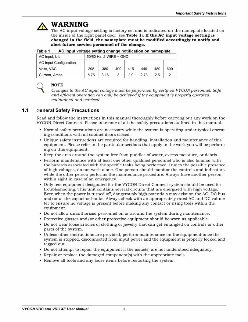
Table 1 AC input voltage setting change notification on nameplate
1.1 General Safety PrecautionsRead and follow the instructions in this manual thoroughly before carrying out any work on the VYCON Direct Connect. Please take note of all the safety precautions outlined in this manual.
• Normal safety precautions are necessary while the system is operating under typical operat-ing conditions with all cabinet doors closed.
• Unique safety instructions are required for handling, installation and maintenance of this equipment. Please refer to the particular sections that apply to the work you will be perform-ing on this equipment.
• Keep the area around the system free from puddles of water, excess moisture, or debris.• Perform maintenance with at least one other qualified personnel who is also familiar with
the hazards associated with the specific tasks being performed. Due to the possible presence of high voltages, do not work alone. One person should monitor the controls and indicators while the other person performs the maintenance procedure. Always have another person within sight in case of an emergency.
• Only test equipment designated for the VYCON Direct Connect system should be used for troubleshooting. This unit contains several circuits that are energized with high voltage. Even when the power is turned off, dangerously high potentials may exist on the AC, DC bus and/or at the capacitor banks. Always check with an appropriately rated AC and DC voltme-ter to ensure no voltage is present before making any contact or using tools within the equipment.
• Do not allow unauthorized personnel on or around the system during maintenance.• Protective glasses and/or other protective equipment should be worn as applicable.• Do not wear loose articles of clothing or jewelry that can get entangled on controls or other
parts of the system.• Unless other instructions are provided, perform maintenance on the equipment once the
system is stopped, disconnected from input power and the equipment is properly locked and tagged out.
• Do not attempt to repair the equipment if the issue(s) are not understood adequately.• Repair or replace the damaged component(s) with the appropriate tools.• Remove all tools and any loose items before restarting the system.
! WARNINGThe AC input voltage setting is factory set and is indicated on the nameplate located on the inside of the right panel door (see Table 1). If the AC input voltage setting is changed in the field, the nameplate must be modified accordingly to notify and alert future service personnel of the change.
AC Input, L-L 50/60 Hz, 2-WIRE + GND
AC Input Configuration
Volts, VAC 208 380 400 415 440 480 600
Current, Amps 5.75 3.16 3 2.9 2.73 2.5 2
NOTEChanges to the AC input voltage must be performed by certified VYCON personnel. Safe and efficient operation can only be achieved if the equipment is properly operated, maintained and serviced.
Important Safety Instructions
VYCON VDC and VDC XE User Manual 3
1.1.1 Ensuring a Safe Work Area
Hazard alert labels and protective guards on potentially dangerous areas of this system protect personnel from exposure to hazards during normal operation and maintenance.
Personnel must know how to recognize and avoid hazardous and potentially hazardous condi-tions associated with this equipment. The consequences of improper or careless operation of VYCON systems can be serious. These systems must be operated and maintained only by trained and qualified personnel.
All personnel installing, servicing and maintaining VYCON systems must be trained in regula-tory requirements and Lockout/Tagout procedures. Lockout/Tagout procedures are required to control and eliminate the potential for harm to service personnel and/or equipment resulting from the accidental startup of equipment or release of stored energy. The Lockout/Tagout proce-dures include attaching a “Do Not Operate” warning tag to the controls before the system is ser-viced. Attach the warning tags to the system and to each operator control station.
Only personnel trained in electrical safety and hazards specific to the system should perform service and maintenance on this equipment as high voltages may be present.
1.1.2 Fire Prevention• Keep the equipment in an area that is ventilated appropriately.• Keep the floor clean of debris or any flammable materials around or on the equipment.• Lubricants and flammable materials are to be stored in properly marked protective contain-
ers in a safe location.• No smoking is permitted in areas that contain flammable material. • Wiring must be properly routed, maintained in good condition and securely attached. • The wiring should be inspected periodically to check for any signs of wear or deterioration.• The wiring and cabling within the equipment or directly connected to the equipment must be
of the recommended gauge size.• All the connections must be secure as required by the connection type and gauge size to pre-
vent arcing or sparks. • Bypassing fuses and/or circuit breakers is prohibited.
1.1.3 Grounding PracticesProper grounding is required to avoid the risk of electrocution and the extreme hazards associ-ated with high voltages and currents. Refer to 3.0 - Site Preparation for details.
Proper grounding is also required to maintain system performance and reliability. Failure to properly ground the equipment may result in unpredictable electrical circuits and electrical activity that may potentially damage associated electronics and communications. All grounds should be inspected periodically to ensure that they are secured, as required by the connection type and gauge size, and are free from corrosion.
! WARNINGModifying the equipment, overriding or failing to follow the safety precautions or recommended procedures could expose service personnel to hazardous conditions. Always follow the safety precautions and recommended procedures. Observe all applicable codes.
! WARNINGHazardous conditions could exist while servicing the system. Do not service the system alone. Make use of other personnel who are familiar with the system hazards and are within visual sight in case of an emergency.
Important Safety Instructions
VYCON VDC and VDC XE User Manual 4
1.1.4 Earthquake SafetyA key aspect associated with the use of industrial equipment is the ability to withstand damage caused by seismic events. Many geographic locations where VYCON systems will be installed are in active seismic zones. The Uniform Building Code rates geographic seismic zones on a scale of 0 through 4.
Industrial equipment is susceptible to various types of damage as a result of an earthquake, which include but are not limited to:
• Water damage • Toppling or overturning
Equipment especially susceptible to toppling over are those with an aspect ratio of greater than 2:1. That is, if the equipment’s height is greater than twice its width or depth, it is prone to toppling or overturning.
• Sliding against and striking other equipment and items Large or heavy equipment has significant momentum attached to it if it starts to move. Once it breaks inertia and begins to slide, it has the potential to cause serious damage to person-nel and anything it strikes.
• Misalignment of components
Refer to 3.0 - Site Preparation for details intended to securely fasten the VYCON Direct Con-nect in its intended location for operational safety and seismic requirements.
1.1.5 Life Support StatementVYCON does not advocate the utilization of its products in any life support applications where a malfunction or failure of its products can potentially result in adverse effects to life support equipment or adversely affect the reliable operation and safety of life support equipment. By no means will VYCON intentionally sell its products into life support applications unless reassurance is provided in writing that appropriate measures have been taken to ensure that the risks associated with malfunction or failure of its products have been minimized, that the customer assumes all associated risks and that the liability of VYCON is safeguarded under such circumstances.
Important Safety Instructions
VYCON VDC and VDC XE User Manual 5
1.2 General Information
1.2.1 Applicable Standards and Certification For distribution in North America, the VYCON Direct Connect is designed to meet the following Underwriter’s Laboratory (UL) applicable requirements:
• UL 508, Standard for Industrial Control Equipment • UL 508C, Standard for Power Conversion Equipment • UL 1004, Standard for Electric Motors
The VYCON Direct Connect is designed in accordance with the pertinent sections of the require-ments outlined in the following:
• National Fire Protection Association (NFPA)• National Electric Code (NEC)• National Electrical Manufacturer’s Association (NEMA)• Occupational Safety & Health Administration (OSHA)
1.2.2 PatentsThe VYCON Direct Connect may be covered by one or more of the following U.S. patents:
• Patent 6,727,617• Patent 6,700,258• Patent 5,315,197• Patent 5,514,924• Patent 5,111,102• Patent 6,897,587
! CAUTIONThis unit complies with the limits for a Class A digital device, pursuant to Part 15 Subpart J of the FCC rules. These limits provide reasonable protection against harmful interference in a commercial environment. This unit generates, uses and radiates radio frequency energy and, if not installed and used in accordance with this instruction manual, may cause harmful interference to radio communications. Operation of this unit in a residential area may cause harmful interference that the user must correct at his own expense.
System Introduction
VYCON VDC and VDC XE User Manual 6
2.0 System Introduction
The VYCON Direct Connect VDC and VDC XE are flywheel energy storage systems consisting of two major subsystems:
• The flywheel module, which includes the high strength steel hub (flywheel rotor), high speed permanent magnet motor/generator and a five axis active magnetic bearing system.
• A three-phase bidirectional Insulated Gate Bipolar Transistor (IGBT) bridge (AC/DC con-verter) used for both motoring and generation.
The output and input to the VDC are through a DC bus connected to the converter. The con-verter creates a sine wave from the DC bus to spin the flywheel during motoring and converts the varying sinusoidal frequency from the flywheel into DC voltage during generation (i.e., energy discharge). Energy is removed from the flywheel rotor by the generator. In the VDC, the energy discharge occurs between a full operating speed of 36K rpm down to 18.5K rpm capable of providing 215 kW (VDC) or 300 kW (VDC XE) of maximum power.
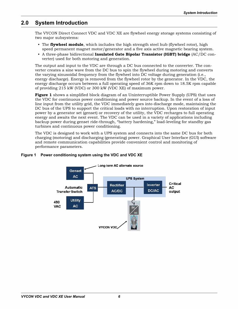
Figure 1 shows a simplified block diagram of an Uninterruptible Power Supply (UPS) that uses the VDC for continuous power conditioning and power source backup. In the event of a loss of line input from the utility grid, the VDC immediately goes into discharge mode, maintaining the DC bus of the UPS to support the critical loads with no interruption. Upon restoration of input power by a generator set (genset) or recovery of the utility, the VDC recharges to full operating energy and awaits the next event. The VDC can be used in a variety of applications including backup power during genset ride-through, “battery hardening,” load-leveling for standby gas turbines and continuous power conditioning.
The VDC is designed to work with a UPS system and connects into the same DC bus for both charging (motoring) and discharging (generating) power. Graphical User Interface (GUI) software and remote communication capabilities provide convenient control and monitoring of performance parameters.
Figure 1 Power conditioning system using the VDC and VDC XE
System Introduction
VYCON VDC and VDC XE User Manual 7
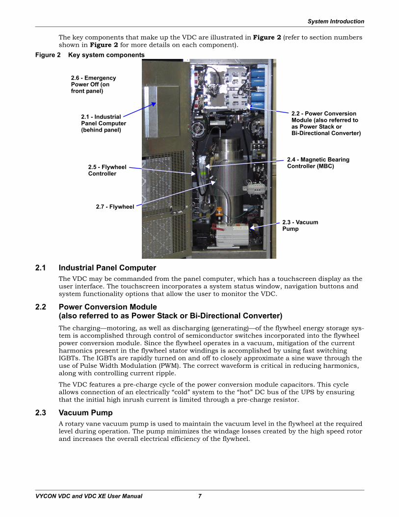
The key components that make up the VDC are illustrated in Figure 2 (refer to section numbers shown in Figure 2 for more details on each component).
Figure 2 Key system components
2.1 Industrial Panel ComputerThe VDC may be commanded from the panel computer, which has a touchscreen display as the user interface. The touchscreen incorporates a system status window, navigation buttons and system functionality options that allow the user to monitor the VDC.
2.2 Power Conversion Module(also referred to as Power Stack or Bi-Directional Converter)The charging—motoring, as well as discharging (generating)—of the flywheel energy storage sys-tem is accomplished through control of semiconductor switches incorporated into the flywheel power conversion module. Since the flywheel operates in a vacuum, mitigation of the current harmonics present in the flywheel stator windings is accomplished by using fast switching IGBTs. The IGBTs are rapidly turned on and off to closely approximate a sine wave through the use of Pulse Width Modulation (PWM). The correct waveform is critical in reducing harmonics, along with controlling current ripple.
The VDC features a pre-charge cycle of the power conversion module capacitors. This cycle allows connection of an electrically “cold” system to the “hot” DC bus of the UPS by ensuring that the initial high inrush current is limited through a pre-charge resistor.
2.3 Vacuum PumpA rotary vane vacuum pump is used to maintain the vacuum level in the flywheel at the required level during operation. The pump minimizes the windage losses created by the high speed rotor and increases the overall electrical efficiency of the flywheel.
2.4 - Magnetic Bearing Controller (MBC)
2.1 - Industrial Panel Computer (behind panel)
2.2 - Power Conversion Module (also referred to as Power Stack or Bi-Directional Converter)
2.3 - Vacuum Pump
2.6 - Emergency Power Off (on front panel)
2.7 - Flywheel
2.5 - Flywheel Controller
System Introduction
VYCON VDC and VDC XE User Manual 8
2.4 Magnetic Bearing Controller (MBC)The magnetic bearing controller provides levitation control of the flywheel hub (rotor) and con-tains a digital controller, a sensor demodulator and current amplifiers. The MBC monitors and controls the position of the flywheel rotor via a five-axis active magnetic bearing system. Rotor position signals are fed to the control module of the MBC, which runs a digital filter compensa-tion program to produce a command signal for each current amplifier. The current amplifiers provide the drive current to the actuators (controllers) of each axis, thereby applying the forces on the rotor maintaining the desired flywheel rotor position.
2.5 Flywheel ControllerThe flywheel controller is the intelligence of the flywheel system and contains a digital controller that monitors and controls the various subsystems within the VDC.
Functions of the flywheel system controller include charging (motoring) and discharging (gener-ating) of the flywheel, controlling and monitoring of the subsystem components and handling system alarms, faults and shutdown.
2.6 Emergency Power OffThe emergency power off feature on the front of the VDC allows the operator to disable the sys-tem in the event of an emergency. The emergency power off may also be activated remotely via a normally open dry contact.
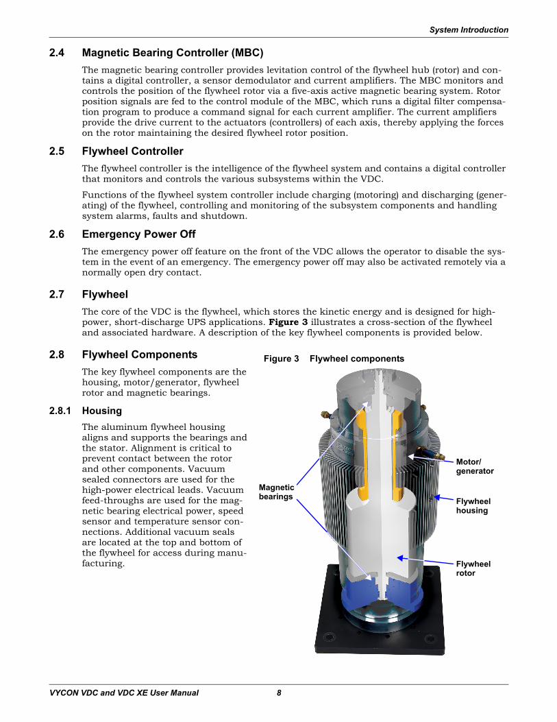
2.7 FlywheelThe core of the VDC is the flywheel, which stores the kinetic energy and is designed for high-power, short-discharge UPS applications. Figure 3 illustrates a cross-section of the flywheel and associated hardware. A description of the key flywheel components is provided below.
2.8 Flywheel ComponentsThe key flywheel components are the housing, motor/generator, flywheel rotor and magnetic bearings.
2.8.1 HousingThe aluminum flywheel housing aligns and supports the bearings and the stator. Alignment is critical to prevent contact between the rotor and other components. Vacuum sealed connectors are used for the high-power electrical leads. Vacuum feed-throughs are used for the mag-netic bearing electrical power, speed sensor and temperature sensor con-nections. Additional vacuum seals are located at the top and bottom of the flywheel for access during manu-facturing.
Figure 3 Flywheel components
Motor/generator
Magneticbearings Flywheel
housing
Flywheel rotor
System Introduction
VYCON VDC and VDC XE User Manual 9
2.8.2 Motor/GeneratorThe motor/generator consists of a unique stator and rotor assembly designed to operate effec-tively in a vacuum environment. The stator assembly is designed to minimize rotor losses that are difficult to remove in a vacuum environment. Stator cooling is accomplished via conductive transfer of heat to the flywheel housing. The permanent magnet of the motor/generator is inte-grated with the flywheel rotor and retained by a high-strength non-magnetic alloy. The magnet retainer also functions as the main stiffness member for the entire flywheel rotor assembly.
2.8.3 Flywheel RotorThe flywheel stores kinetic energy in the form of a rotating mass. The rotor hub (flywheel rotor) is manufactured from a high-strength grade steel. At full operating speed, the stress levels in the rotor provide an ample safety factor, meeting stringent criteria for design life, flaw tolerance and cyclic life for UPS applications.
2.8.4 Magnetic BearingsMagnetic bearings are used for rotor support. The bearings fully levitate and suspend the rotor in a magnetic field, responding to both static and dynamic forces. The magnetic bearings pro-vide radial and axial support. To minimize bearing power requirements and losses, the flywheel is vertically oriented, requiring only the axial bearing axis to support the full rotor weight.
Magnetic bearings possess unique advantages in operation and longevity of flywheel systems. These advantages include extremely long life with no maintenance, high reliability, tolerance to unbalance, minimum rotor losses and low power consumption.
Site Preparation
VYCON VDC and VDC XE User Manual 10
3.0 Site PreparationMinimal site preparation is required for installation of the VDC. Before installation, consider-ation must be given to:
• Wiring and cabling to UPS and other equipment• Service access• Exhaust requirements• Floor mounting
Be sure to review this section, along with the installation drawings provided with this manual and listed in 12.0 - Installation Drawings, prior to installation.
3.1 Space RequirementsThe VDC requires 6.76 sq. ft. (0.63 sq. m.) of floor space. A 36-in. (914mm) clearance in front is required for National Electrical Code compliance, and a 12-in. (305mm) clearance above the unit is required for cooling. The unit accommodates bottom entry for power and control cables; this must be taken into consideration while planning for product installation.
3.2 Floor LoadingThe VDC should be mounted on a finished surface, such as concrete, block, brick or wood. The floor must be strong enough to support the equipment load and must be suitable for anchoring. The floor must be within 3 degrees—±2.52 in. (64mm) over a 48-in. (1219mm) span—of being level.The floor mounting pattern for anchoring is detailed in Facilities Interface Diagram, VDC and VDC XE.
3.3 Environmental Considerations• Clean, dust-free environment.• Install away from overhead water lines.• Ambient operating temperature range is -4ºF to 104ºF (-20ºC to 40ºC).• Minimum cold start temperature is 32ºF (0ºC).• Relative humidity must be less than 95%, non-condensing.
Note that room ventilation is necessary, but air conditioning may not be required. Maximum ambient operating temperature is 104ºF (40ºC) without derating.
3.4 Facility Power RequirementsProtected AC power is required for proper operation of the VDC. System control power is derived from this protected AC source; it also provides power for the cooling fans and the vacuum pump.The protected AC power should come from the critical bus of a UPS system. The VDC can accommodate 208, 380, 400, 415, 440, 480 or 600 VAC L1, L2, +G, 50/60Hz.
3.5 Wiring ConsiderationsA qualified electrician must perform all electrical connections. All external wiring (DC & AC Power, Control and Grounding) are to be provided by the electrical contractor. All wire sizes and installation must comply with all applicable local, regional and national electrical codes.Verify that all incoming high and low voltage power circuits are de-energized and locked out before installing the cables and making connections.Facilities Interface Diagram, VDC and VDC XE identifies the locations of the cable access areas. The VDC can accommodate bottom (standard) or top (optional) access. Remove and punch the conduit landing plates and re-install prior to connecting any wiring. Do not cut or punch the conduit landing plates while attached to the VDC. After reattaching the landing plates, ensure there are no metal shavings, wire fragments, etc., inside the unit.Each cable group must be run in a separate grounded rigid metal conduit to prevent control sig-nal interference. Please refer to Interconnect Diagram, VDC and VDC XE.It is recommended that the VDC be placed as close as possible to the mating UPS.
Handling And Unpacking
VYCON VDC and VDC XE User Manual 11
4.0 Handling And Unpacking
The VDC has sensitive electrical and mechanical components that have been calibrated prior to shipment and as such, the equipment is shipped in an air ride truck.
The VDC is designed to be handled using either a forklift or a pallet jack. Overhead lifting equip-ment may also be used in conjunction with straps. Care must be taken to prevent damage or personnel injury while handling or unpacking the equipment.
4.1 Inspecting the SystemUpon delivery of the VDC, inspect the equipment and shipping skid for any signs of damage or mishandling. Shock and tilt gauges indicate excessive shock and/or tilt.
If any damage is noted, file a claim with the shipping agency within 24 hours and notify your VYCON sales representative of the damage and condition of the equipment.
Do not attempt to install any equipment suspected of damage during shipment.
4.2 Moving and Handling
Check and verify the capacity of the forklift or pallet jack is sufficient for the weight of the VDC. When transporting using a forklift or pallet jack, check and verify the forks extend beyond the full depth of the cabinet.
Using straps, an overhead lifting device may be used to transport the VDC. Check and verify the capacity of the overhead lifting device and straps are sufficient for the weight of the equipment.
The VDC has sensitive electrical and mechanical components that have been calibrated prior to shipment. When transporting, maintain minimum tilt from vertical at all times and do not sub-ject the equipment to excessive shock and/or vibration. The unit must not be subjected to more than 15 degrees of tilt.
Exhibit care when handling the VDC to avoid equipment damage or personnel injury.
NOTEThe VDC with shipping material weighs up to 1,500 lb. (680 kg). It must be handled with care and maintained in an upright position, paying particular attention to the center of gravity of the equipment. Arrows on the packing equipment indicate the upright position.
Handling And Unpacking
VYCON VDC and VDC XE User Manual 12
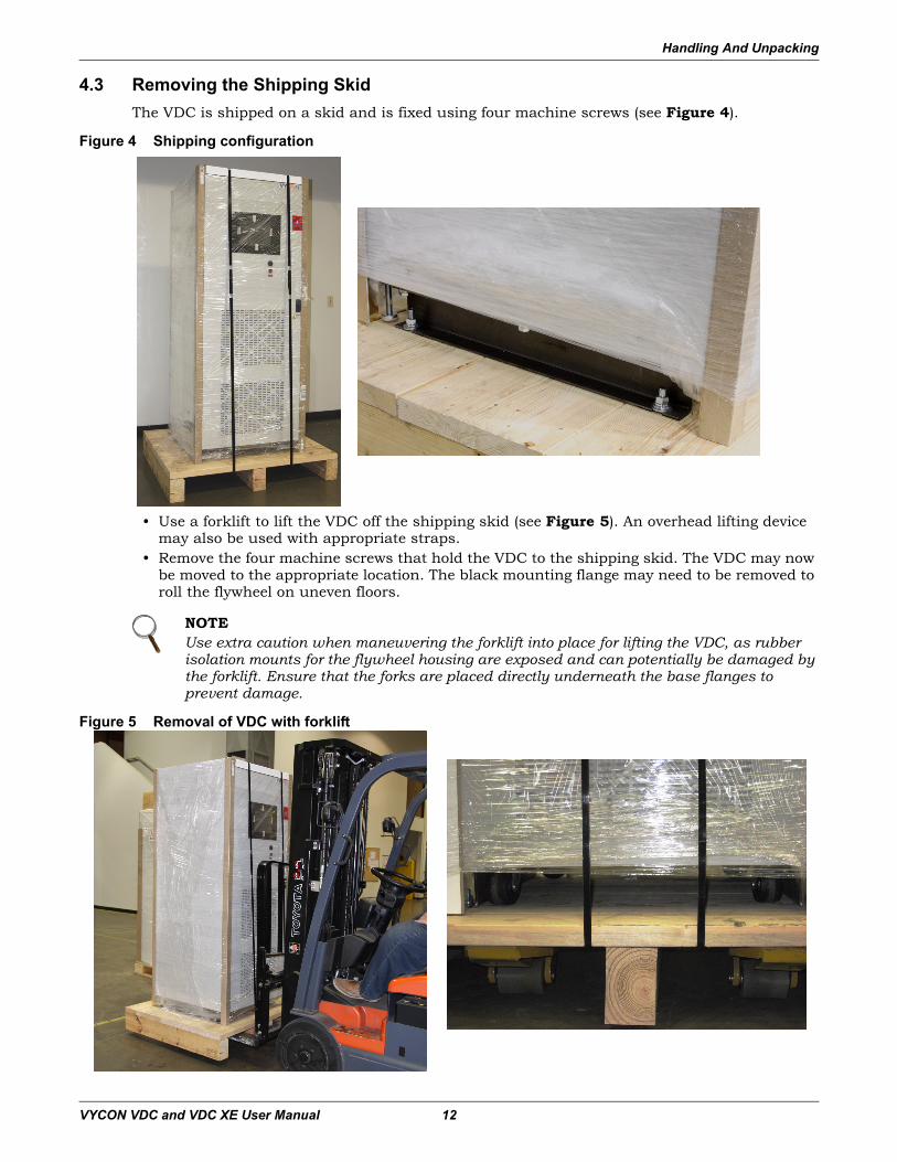
4.3 Removing the Shipping SkidThe VDC is shipped on a skid and is fixed using four machine screws (see Figure 4).
Figure 4 Shipping configuration
• Use a forklift to lift the VDC off the shipping skid (see Figure 5). An overhead lifting device may also be used with appropriate straps.
• Remove the four machine screws that hold the VDC to the shipping skid. The VDC may now be moved to the appropriate location. The black mounting flange may need to be removed to roll the flywheel on uneven floors.
Figure 5 Removal of VDC with forklift
NOTEUse extra caution when maneuvering the forklift into place for lifting the VDC, as rubber isolation mounts for the flywheel housing are exposed and can potentially be damaged by the forklift. Ensure that the forks are placed directly underneath the base flanges to prevent damage.
Handling And Unpacking
VYCON VDC and VDC XE User Manual 13
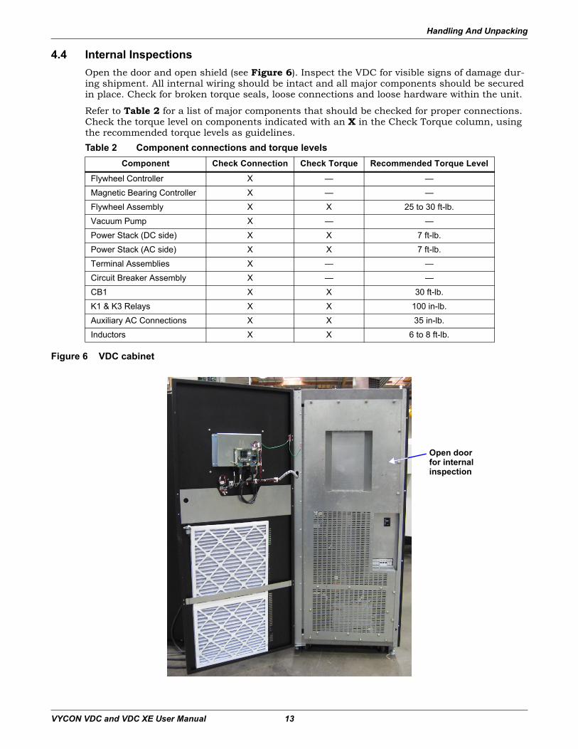
4.4 Internal InspectionsOpen the door and open shield (see Figure 6). Inspect the VDC for visible signs of damage dur-ing shipment. All internal wiring should be intact and all major components should be secured in place. Check for broken torque seals, loose connections and loose hardware within the unit.
Refer to Table 2 for a list of major components that should be checked for proper connections. Check the torque level on components indicated with an X in the Check Torque column, using the recommended torque levels as guidelines.
Figure 6 VDC cabinet
Table 2 Component connections and torque levelsComponent Check Connection Check Torque Recommended Torque Level
Flywheel Controller X — —
Magnetic Bearing Controller X — —
Flywheel Assembly X X 25 to 30 ft-lb.
Vacuum Pump X — —
Power Stack (DC side) X X 7 ft-lb.
Power Stack (AC side) X X 7 ft-lb.
Terminal Assemblies X — —
Circuit Breaker Assembly X — —
CB1 X X 30 ft-lb.
K1 & K3 Relays X X 100 in-lb.
Auxiliary AC Connections X X 35 in-lb.
Inductors X X 6 to 8 ft-lb.
Open door for internal inspection
Installation
VYCON VDC and VDC XE User Manual 14
5.0 Installation
5.1 Installation GuidelinesInstall your VDC in accordance with the instructions, guidelines and drawings included with this manual, following all procedures.
• Select a location away from overhead water lines to prevent water damage in case of acciden-tal leaks.
• Route cables such that runs are as short as possible.• Locate the VDC for easy connection of inputs, outputs and auxiliary equipment.• Allow enough space to service the VDC.
• Ensure air circulation is sufficient to expel heat produced by the VDC.• Protect against moisture and excessive humidity (not to exceed 95% non-condensing).• Protect against excessive dust and other particulate matter.• Ensure installation is in compliance with fire prevention regulations and practices.• Install in an area that provides an operating environment temperature of -4°F to +104°F
(-20°C to +40°C).• Avoid placing the unit in direct sunlight or other heat sources.• Make sure that the floor can support the weight of the VDC.• If the VDC will not be immediately installed, store indoors in a clean, dry area where the
temperature will be between -13°F to +158°F (-25°C to +70°C) and the humidity does not exceed 95% (non-condensing).
! CAUTIONOnly qualified personnel must perform the initial system check-out and startup to ensure proper equipment operation. Failure to do so may void your warranty. Contact your VYCON Service Representative to arrange for system check-out and startup.
NOTERefer to 3.0 - Site Preparation for service clearance requirements for the VDC.
Installation
VYCON VDC and VDC XE User Manual 15
5.2 System AnchoringThe following tools and equipment are required for floor anchoring:
• Transport/handling equipment such as a forklift or pallet jackBefore moving, check and verify to ensure the handling equipment is capable of supporting the weight of the VDC.
• Open-end wrench• Socket wrench with appropriate ratchet handle• Drill and masonry drill bit• Hammer and/or mallet• Expansion bolts• Torque wrench
Installation ProcedureThe following procedure is for the use of expansion anchors; other methods may be used.
1. Prepare a clean, level finished surface, free of obstructions, cracks and seams in the vicinity of the installation. Ensure all clearances are maintained and the area for bottom entry (if used) is clear.
2. Locate the position for the mounting holes; see Facilities Interface Diagram, VDC and VDC XE.
3. Drill mounting holes large enough for the expansion anchors.4. Drop expansion anchors in the mounting holes, using a mallet, as necessary, to make sure
the expansion anchors are flush with the floor.5. Using a mallet or hammer, tap the setter rod (if any) to set the expansion anchors in place.
Remove the setter rod.6. Using a forklift or a pallet jack, move the VDC into place; straps can also be used to lift the
unit and set it in place. Place the unit such that the holes in the C channel align with the mounting holes.
7. Insert all four anchor bolts and tighten to the appropriate torque as specified by the manufacturer.
5.3 System WiringRefer to 12.0 - Installation Drawings for location of terminals and cable routing information. All wire sizes and installation must comply with local, regional and national electrical codes.
Verify that all incoming high and low voltage power circuits are de-energized and locked out before installing the cables and making connections.
Each cable group must be run in a separate grounded rigid metal conduit to prevent control sig-nal interference. See Interconnect Diagram, VDC and VDC XE.
Installation
VYCON VDC and VDC XE User Manual 16
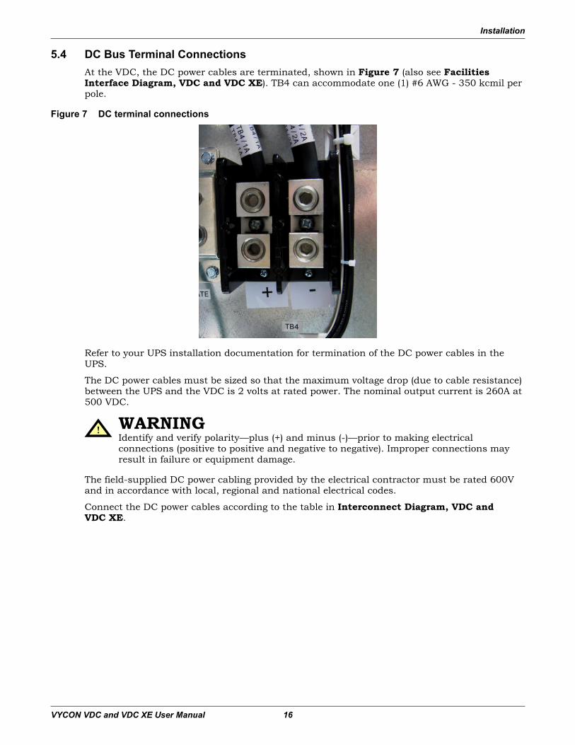
5.4 DC Bus Terminal ConnectionsAt the VDC, the DC power cables are terminated, shown in Figure 7 (also see Facilities Interface Diagram, VDC and VDC XE). TB4 can accommodate one (1) #6 AWG - 350 kcmil per pole.
Figure 7 DC terminal connections
Refer to your UPS installation documentation for termination of the DC power cables in the UPS.
The DC power cables must be sized so that the maximum voltage drop (due to cable resistance) between the UPS and the VDC is 2 volts at rated power. The nominal output current is 260A at 500 VDC.
The field-supplied DC power cabling provided by the electrical contractor must be rated 600V and in accordance with local, regional and national electrical codes.
Connect the DC power cables according to the table in Interconnect Diagram, VDC and VDC XE.
! WARNINGIdentify and verify polarity—plus (+) and minus (-)—prior to making electrical connections (positive to positive and negative to negative). Improper connections may result in failure or equipment damage.
Installation
VYCON VDC and VDC XE User Manual 17
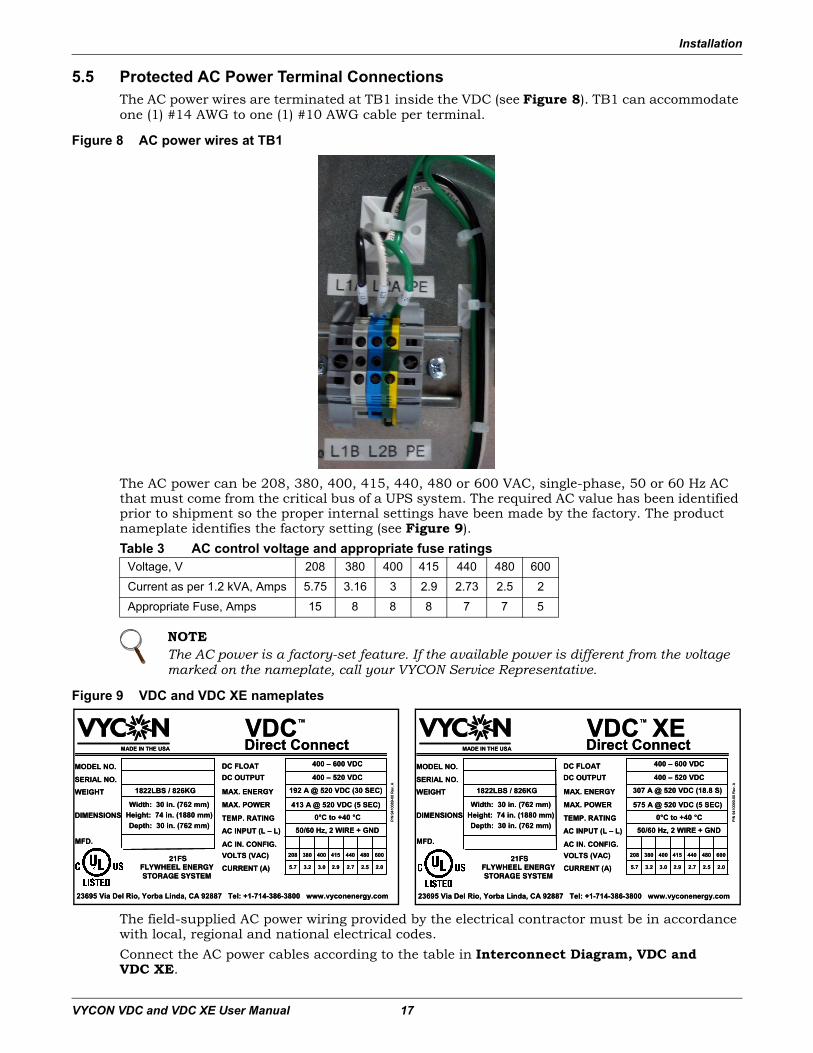
5.5 Protected AC Power Terminal ConnectionsThe AC power wires are terminated at TB1 inside the VDC (see Figure 8). TB1 can accommodate one (1) #14 AWG to one (1) #10 AWG cable per terminal.
Figure 8 AC power wires at TB1
The AC power can be 208, 380, 400, 415, 440, 480 or 600 VAC, single-phase, 50 or 60 Hz AC that must come from the critical bus of a UPS system. The required AC value has been identified prior to shipment so the proper internal settings have been made by the factory. The product nameplate identifies the factory setting (see Figure 9).Table 3 AC control voltage and appropriate fuse ratings
Figure 9 VDC and VDC XE nameplates
The field-supplied AC power wiring provided by the electrical contractor must be in accordance with local, regional and national electrical codes.Connect the AC power cables according to the table in Interconnect Diagram, VDC and VDC XE.
Voltage, V 208 380 400 415 440 480 600
Current as per 1.2 kVA, Amps 5.75 3.16 3 2.9 2.73 2.5 2
Appropriate Fuse, Amps 15 8 8 8 7 7 5
NOTEThe AC power is a factory-set feature. If the available power is different from the voltage marked on the nameplate, call your VYCON Service Representative.
400 – 600 VDC
MADE IN THE USA
MODEL NO.
SERIAL NO.
MFD.
DIMENSIONS
WEIGHT
DC OUTPUTDC FLOAT
MAX. ENERGY
AC INPUT (L – L)
P/N
941
0089
-00
Rev
. A
CURRENT (A)
VOLTS (VAC)AC IN. CONFIG.
VDCTM
Direct Connect
FLYWHEEL ENERGY STORAGE SYSTEM
413 A @ 520 VDC (5 SEC)
192 A @ 520 VDC (30 SEC)
400 – 520 VDC
MAX. POWER
50/60 Hz, 2 WIRE + GND
415400208
Width: 30 in. (762 mm)Height: 74 in. (1880 mm)Depth: 30 in. (762 mm)
1822LBS / 826KG
TEMP. RATING 0°C to +40 °C
23695 Via Del Rio, Yorba Linda, CA 92887 Tel: +1-714-386-3800 www.vyconenergy.com
480440
2.93.03.25.7 2.52.7
600
2.021FS 380
400 – 600 VDC
MADE IN THE USA
MODEL NO.
SERIAL NO.
MFD.
DIMENSIONS
WEIGHT
DC OUTPUTDC FLOAT
MAX. ENERGY
AC INPUT (L – L)
P/N
941
0090
-00
Rev
. A
CURRENT (A)
VOLTS (VAC)AC IN. CONFIG.
VDC XETM
Direct Connect
FLYWHEEL ENERGY STORAGE SYSTEM
575 A @ 520 VDC (5 SEC)
307 A @ 520 VDC (18.8 S)
400 – 520 VDC
MAX. POWER
50/60 Hz, 2 WIRE + GND
415400208
Width: 30 in. (762 mm)Height: 74 in. (1880 mm)Depth: 30 in. (762 mm)
1822LBS / 826KG
TEMP. RATING 0°C to +40 °C
23695 Via Del Rio, Yorba Linda, CA 92887 Tel: +1-714-386-3800 www.vyconenergy.com
480440
2.93.03.25.7 2.52.7
600
2.021FS 380
Installation
VYCON VDC and VDC XE User Manual 18
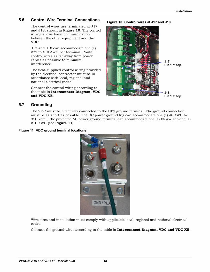
5.6 Control Wire Terminal ConnectionsThe control wires are terminated at J17 and J18, shown in Figure 10. The control wiring allows basic communication between the other equipment and the VDC.
J17 and J18 can accommodate one (1) #22 to #10 AWG per terminal. Route control wires as far away from power cables as possible to minimize interference.
The field-supplied control wiring provided by the electrical contractor must be in accordance with local, regional and national electrical codes.
Connect the control wiring according to the table in Interconnect Diagram, VDC and VDC XE.
5.7 GroundingThe VDC must be effectively connected to the UPS ground terminal. The ground connection must be as short as possible. The DC power ground lug can accommodate one (1) #6 AWG to 350 kcmil; the protected AC power ground terminal can accommodate one (1) #4 AWG to one (1) #10 AWG (see Figure 11).
Figure 11 VDC ground terminal locations
Wire sizes and installation must comply with applicable local, regional and national electrical codes.
Connect the ground wires according to the table in Interconnect Diagram, VDC and VDC XE.
Figure 10 Control wires at J17 and J18
J18Pin 1 at top
J17Pin 1 at top
Front Panel Touchscreen
VYCON VDC and VDC XE User Manual 19
6.0 Front Panel Touchscreen
The VDC features a user-friendly touchscreen interface as the primary means for the operator to monitor and control the system. The touchscreen provides information about the operation of the VDC, as well as buttons to start and stop the VDC.
The touchscreen displays an assortment of information including system information, system status, system errors and operating parameters such as DC bus voltage and DC bus current. It also offers access to event logs showing charge, discharge, warning and alarm events that have occurred.
This section explains how to navigate through the touchscreens and the type of information dis-played. The touchscreen has a Main Screen and three submenus described in the rest of this section, as shown in Table 4.
Audible AlarmThe VDC includes an audible alarm that will sound when a warning or fault occurs. To reset the audible alarm, touch the horn silence icon on the touch panel main screen. The horn will again sound should a new warning or alarm occur. During initial start-up the horn may sound and can be reset by following the instructions above.
Table 4 Overview of touchscreen descriptionsSection Description
6.1 - Main Screen
Main display screen that displays general status information, including system date and time, and has buttons to start and stop the VDC and buttons to access the three submenus.An audible alarm sounds when a warning or fault occurs. Touch the Horn Silence button on the Main Screen to reset the audible alarm.
6.2 - Discharge Events Log Submenu that displays a log of charge and discharge events.
6.3 - Warning/Alarm Events Log Submenu that displays a log of warning and alarm events and warning and alarm codes for technician use.
6.4 - Operating Parameters Submenu that displays general system information and fault parameters.
6.5 - System Modes Details about the VDC’s 11 system modes.
6.6 - Software Control Parameters Information about the factory-set control parameters.
Front Panel Touchscreen
VYCON VDC and VDC XE User Manual 20
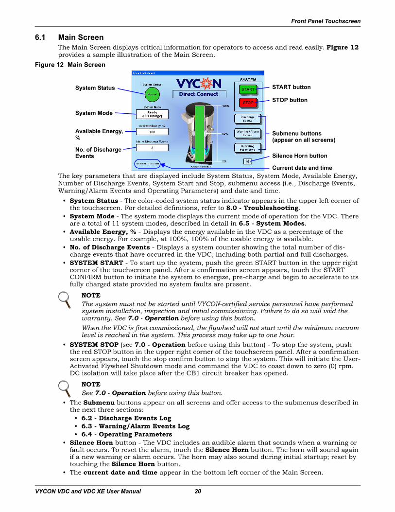
6.1 Main ScreenThe Main Screen displays critical information for operators to access and read easily. Figure 12 provides a sample illustration of the Main Screen.
Figure 12 Main Screen
The key parameters that are displayed include System Status, System Mode, Available Energy, Number of Discharge Events, System Start and Stop, submenu access (i.e., Discharge Events, Warning/Alarm Events and Operating Parameters) and date and time.
• System Status - The color-coded system status indicator appears in the upper left corner of the touchscreen. For detailed definitions, refer to 8.0 - Troubleshooting.
• System Mode - The system mode displays the current mode of operation for the VDC. There are a total of 11 system modes, described in detail in 6.5 - System Modes.
• Available Energy, % - Displays the energy available in the VDC as a percentage of the usable energy. For example, at 100%, 100% of the usable energy is available.
• No. of Discharge Events - Displays a system counter showing the total number of dis-charge events that have occurred in the VDC, including both partial and full discharges.
• SYSTEM START - To start up the system, push the green START button in the upper right corner of the touchscreen panel. After a confirmation screen appears, touch the START CONFIRM button to initiate the system to energize, pre-charge and begin to accelerate to its fully charged state provided no system faults are present.
• SYSTEM STOP (see 7.0 - Operation before using this button) - To stop the system, push the red STOP button in the upper right corner of the touchscreen panel. After a confirmation screen appears, touch the stop confirm button to stop the system. This will initiate the User-Activated Flywheel Shutdown mode and command the VDC to coast down to zero (0) rpm. DC isolation will take place after the CB1 circuit breaker has opened.
• The Submenu buttons appear on all screens and offer access to the submenus described in the next three sections:
• 6.2 - Discharge Events Log • 6.3 - Warning/Alarm Events Log • 6.4 - Operating Parameters
• Silence Horn button - The VDC includes an audible alarm that sounds when a warning or fault occurs. To reset the alarm, touch the Silence Horn button. The horn will sound again if a new warning or alarm occurs. The horn may also sound during initial startup; reset by touching the Silence Horn button.
• The current date and time appear in the bottom left corner of the Main Screen.
NOTEThe system must not be started until VYCON-certified service personnel have performed system installation, inspection and initial commissioning. Failure to do so will void the warranty. See 7.0 - Operation before using this button.When the VDC is first commissioned, the flywheel will not start until the minimum vacuum level is reached in the system. This process may take up to one hour.
NOTESee 7.0 - Operation before using this button.
START buttonSystem Status
Submenu buttons(appear on all screens)
System Mode
Available Energy,%
No. of Discharge Events
STOP button
Current date and time
Silence Horn button
Front Panel Touchscreen
VYCON VDC and VDC XE User Manual 21
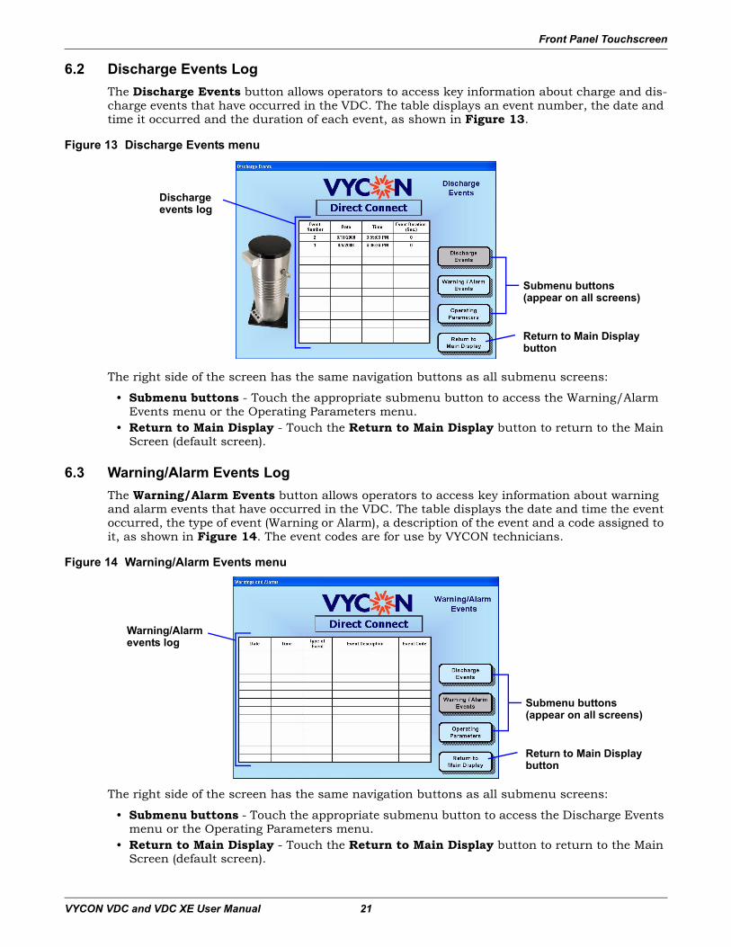
6.2 Discharge Events LogThe Discharge Events button allows operators to access key information about charge and dis-charge events that have occurred in the VDC. The table displays an event number, the date and time it occurred and the duration of each event, as shown in Figure 13.
Figure 13 Discharge Events menu
The right side of the screen has the same navigation buttons as all submenu screens:
• Submenu buttons - Touch the appropriate submenu button to access the Warning/Alarm Events menu or the Operating Parameters menu.
• Return to Main Display - Touch the Return to Main Display button to return to the Main Screen (default screen).
6.3 Warning/Alarm Events LogThe Warning/Alarm Events button allows operators to access key information about warning and alarm events that have occurred in the VDC. The table displays the date and time the event occurred, the type of event (Warning or Alarm), a description of the event and a code assigned to it, as shown in Figure 14. The event codes are for use by VYCON technicians.
Figure 14 Warning/Alarm Events menu
The right side of the screen has the same navigation buttons as all submenu screens:
• Submenu buttons - Touch the appropriate submenu button to access the Discharge Events menu or the Operating Parameters menu.
• Return to Main Display - Touch the Return to Main Display button to return to the Main Screen (default screen).
Submenu buttons(appear on all screens)
Return to Main Displaybutton
Dischargeevents log
Warning/Alarm events log
Submenu buttons(appear on all screens)
Return to Main Displaybutton
Front Panel Touchscreen
VYCON VDC and VDC XE User Manual 22
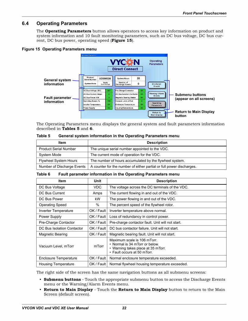
6.4 Operating ParametersThe Operating Parameters button allows operators to access key information on product and system information and 10 fault monitoring parameters, such as DC bus voltage, DC bus cur-rent, DC bus power, operating speed (Figure 15).
Figure 15 Operating Parameters menu
The Operating Parameters menu displays the general system and fault parameters information described in Tables 5 and 6.
The right side of the screen has the same navigation buttons as all submenu screens:
• Submenu buttons - Touch the appropriate submenu button to access the Discharge Events menu or the Warning/Alarm Events menu.
• Return to Main Display - Touch the Return to Main Display button to return to the Main Screen (default screen).
Table 5 General system information in the Operating Parameters menuItem Description
Product Serial Number The unique serial number appointed to the VDC.System Mode The current mode of operation for the VDC.Flywheel System Hours The number of hours accumulated by the flywheel system.Number of Discharge Events A counter for the number of either partial or full power discharges.
Table 6 Fault parameter information in the Operating Parameters menuItem Unit Description
DC Bus Voltage VDC The voltage across the DC terminals of the VDC.DC Bus Current Amps The current flowing in and out of the VDC.DC Bus Power kW The power flowing in and out of the VDC.Operating Speed % The percent speed of the flywheel rotor.Inverter Temperature OK / Fault Inverter temperature above normal.Power Supply OK / Fault Loss of redundancy in control power.Pre-Charge Contactor OK / Fault Pre-charge contactor fault. Unit will not start.DC Bus Isolation Contactor OK / Fault DC bus contactor failure. Unit will not start.Magnetic Bearing OK / Fault Magnetic bearing fault. Unit will not start.
Vacuum Level, mTorr mTorr
Maximum scale is 106 mTorr.• Normal is 34 mTorr or below. • Warning takes place at 35 mTorr.• Fault occurs at 50 mTorr.
Enclosure Temperature OK / Fault Normal enclosure temperature exceeded.Housing Temperature OK / Fault Normal flywheel housing temperature exceeded.
Submenu buttons(appear on all screens)
General system information
Fault parameter information
Return to Main Displaybutton
Front Panel Touchscreen
VYCON VDC and VDC XE User Manual 23
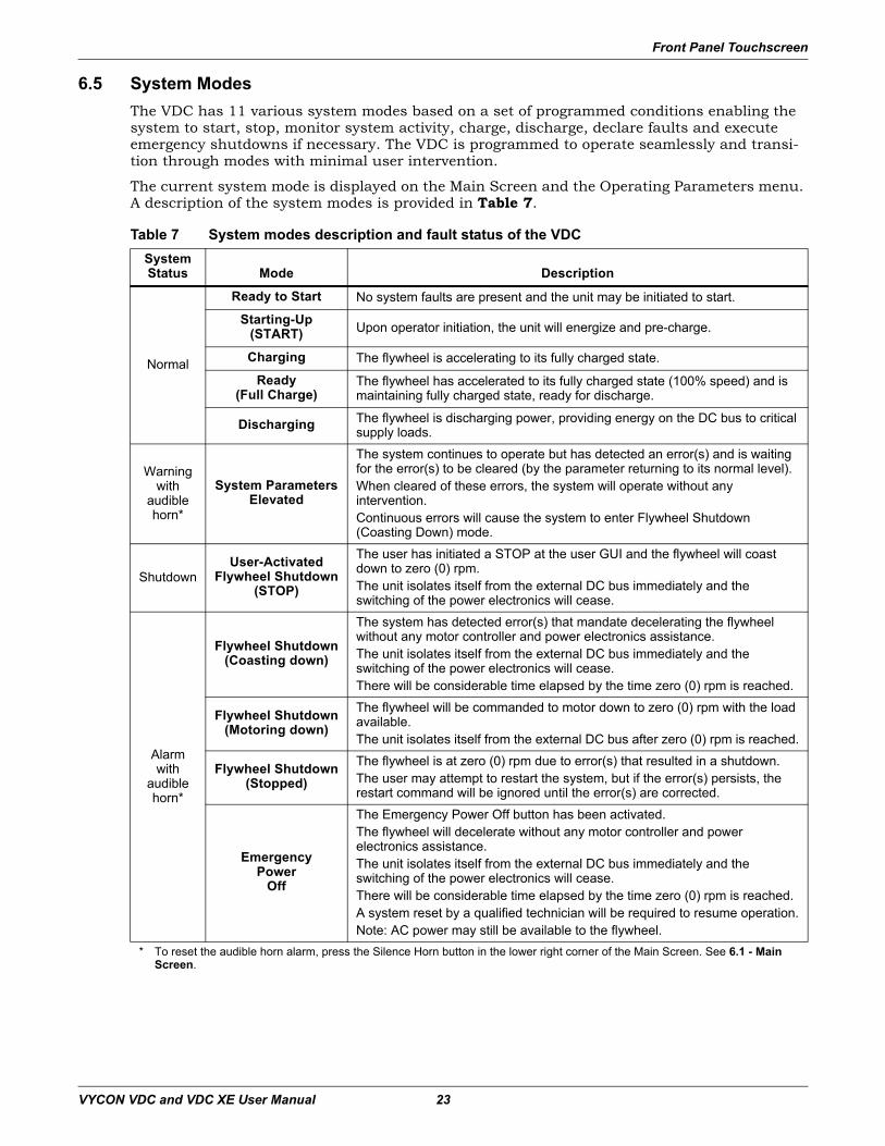
6.5 System ModesThe VDC has 11 various system modes based on a set of programmed conditions enabling the system to start, stop, monitor system activity, charge, discharge, declare faults and execute emergency shutdowns if necessary. The VDC is programmed to operate seamlessly and transi-tion through modes with minimal user intervention.
The current system mode is displayed on the Main Screen and the Operating Parameters menu. A description of the system modes is provided in Table 7.
Table 7 System modes description and fault status of the VDCSystemStatus Mode Description
Normal
Ready to Start No system faults are present and the unit may be initiated to start.
Starting-Up(START) Upon operator initiation, the unit will energize and pre-charge.
Charging The flywheel is accelerating to its fully charged state.
Ready(Full Charge)
The flywheel has accelerated to its fully charged state (100% speed) and ismaintaining fully charged state, ready for discharge.
Discharging The flywheel is discharging power, providing energy on the DC bus to criticalsupply loads.
Warning with
audible horn*
System ParametersElevated
The system continues to operate but has detected an error(s) and is waiting for the error(s) to be cleared (by the parameter returning to its normal level).When cleared of these errors, the system will operate without anyintervention.Continuous errors will cause the system to enter Flywheel Shutdown(Coasting Down) mode.
ShutdownUser-Activated
Flywheel Shutdown(STOP)
The user has initiated a STOP at the user GUI and the flywheel will coast down to zero (0) rpm.The unit isolates itself from the external DC bus immediately and the switching of the power electronics will cease.
Alarm with
audible horn*
Flywheel Shutdown(Coasting down)
The system has detected error(s) that mandate decelerating the flywheelwithout any motor controller and power electronics assistance.The unit isolates itself from the external DC bus immediately and the switching of the power electronics will cease.There will be considerable time elapsed by the time zero (0) rpm is reached.
Flywheel Shutdown(Motoring down)
The flywheel will be commanded to motor down to zero (0) rpm with the loadavailable.The unit isolates itself from the external DC bus after zero (0) rpm is reached.
Flywheel Shutdown(Stopped)
The flywheel is at zero (0) rpm due to error(s) that resulted in a shutdown.The user may attempt to restart the system, but if the error(s) persists, therestart command will be ignored until the error(s) are corrected.
EmergencyPower
Off
The Emergency Power Off button has been activated.The flywheel will decelerate without any motor controller and powerelectronics assistance.The unit isolates itself from the external DC bus immediately and the switching of the power electronics will cease.There will be considerable time elapsed by the time zero (0) rpm is reached.A system reset by a qualified technician will be required to resume operation.Note: AC power may still be available to the flywheel.
* To reset the audible horn alarm, press the Silence Horn button in the lower right corner of the Main Screen. See 6.1 - Main Screen.
Front Panel Touchscreen
VYCON VDC and VDC XE User Manual 24
6.6 Software Control ParametersThe control parameters are configured and factory-set for each system. The control parameters depend on the type of UPS and the application of the VDC. Three control parameters are config-ured: regulation voltage, charge voltage and charge current range. Table 8 illustrates the con-trol parameters and ranges for the various control parameters.Table 8 Software control parameter setting
Control Parameter Unit Range
Regulation Voltage VDC 400 - 520
Charge Voltage VDC 420 - 600
Charge Current Amps 10 - 50
NOTEOnly qualified and trained personnel are permitted to change the control parameter values. These values may require adjustments due to battery type or initial system startup related issues.
The actual setpoints for the system must be recorded on the commissioning checklist.
Operation
VYCON VDC and VDC XE User Manual 25
7.0 Operation
7.1 Visual and Mechanical Inspection Before Initial System StartupA VYCON-certified service provider will perform these tasks prior to initial system startup:
• Conduct an overall visual inspection of the VDC.• Check the vacuum pump oil level and condition.• Verify all electrical connections are properly connected, including DC input power, auxiliary
AC input power, grounding, control wiring and emergency shutdown wiring.• Verify that the system is properly anchored and installed per VYCON recommendations.
7.2 Initial System Startup ProcedureA VYCON-certified service provider will carry out or direct the following tasks:
• Inspect the system before the initial startup.• Ensure that the commissioning documents are complete per VYCON specifications.• Conduct basic training on the VDC operation to operators.• Support the initial system startup.• Verify the software control parameters.
! CAUTIONThe initial system startup must be performed by a VYCON-certified service provider to ensure proper system operation. Failure to follow the initial system startup procedure instructions will void system warranty.
Operation
VYCON VDC and VDC XE User Manual 26
7.3 Typical System Startup Procedure
7.3.1 System Inspection Prior to StartupPrior to a typical system startup, the following must be performed on the VDC:
1. Make sure that no tools are in the cabinet and the protective cabinet panels are in place.2. Check the vacuum pump oil level and condition.3. Check to be sure EPO button is not in Latched Off position.4. Verify that DC power is connected to the UPS DC bus.5. Verify that auxiliary AC power is connected to the system.6. Switch ON the auxiliary AC power to the VDC. An audible alarm may sound; reset by
touching the Silence Horn button after the touchscreen boots up. Check and verify the front panel touchscreen boots up without errors and the system fans are operational.
7. Wait until the vacuum system reaches full vacuum conditions.
8. Check for oil leaks in and around the VDC vacuum pump.9. Ensure that the cabinet doors are closed and locked.10. Proceed to 7.3.2 - Startup of VDC.
7.3.2 Startup of VDCFollow these steps to power up the VDC:
1. Start the UPS according to the instructions in the UPS manufacturer’s user manual.
2. Check that the DC bus voltage of the UPS is at the minimum system voltage requirements for the VDC before a START command is initiated.
3. When indicated by the UPS startup instructions, close the input circuit breaker (CB1) to the VDC.
4. Ensure that the cabinet door is closed and locked. The VDC is now ready for a START command to be initiated.
5. Push the SYSTEM START button on the Main Screen of the touchscreen panel, and a confirmation screen appears.
6. Touch the START confirm button to proceed. The system will carry out several internal checks and then initiate the Starting-Up (START) system mode.
7. The system will automatically proceed through modes of operation including the Charging and Ready (Full Charge) system modes. Upon reaching the Ready (Full charge) system mode, the system is online, fully charged and ready for ride-through support needs. A detailed description of the system modes can be found in 6.5 - System Modes.
NOTEA typical system startup is defined as any startup that takes place after the initial system commissioning.
The following procedure assumes that system installation, inspection and initial system startup have been performed by VYCON-certified service personnel. VYCON-certified service personnel must perform system installation, inspection and initial startup. Failure to do so will void the warranty.
NOTEUpon first commissioning of the VDC, the system may require about 1 hour to reach the required vacuum level.
NOTEStartup instructions for UPS models will vary from manufacturer to manufacturer. Consult the respective UPS user manual for startup instructions.
Operation
VYCON VDC and VDC XE User Manual 27
7.4 System Shutdown SequenceTwo procedures are available for shutting down the VDC:
1. A Normal Shutdown initiated by pressing the SYSTEM STOP button on the Main Screen display, then verifying the choice in the confirmation screen.
2. An Emergency Power Off (EPO) initiated by any of the following methods:• Local emergency shutdown button activated• Remote emergency shutdown button activated (if connected)• UPS emergency shutdown button activated (if connected)
7.4.1 Normal ShutdownThe touchscreen STOP button is recommended for all normal shutdowns. To initiate a normal shutdown:
• Touch the SYSTEM STOP button in the upper right corner of the main screen of the touch-screen panel, and a confirmation screen appears.
• Touch the STOP confirm button to proceed.• The flywheel enters a coast mode where the flywheel slowly spins down.• DC power sources are automatically disconnected from the system via CB1.
7.4.2 Emergency Power Off (EPO)Press the Emergency Power Off button to remove power from the system under emergency con-ditions only. The emergency power off circuitry isolates the system immediately, placing the entire system, except for UPS-powered circuits, in the following safe shutdown condition:
• The flywheel enters a coast mode where the flywheel slowly spins down.• DC power sources are automatically disconnected from the system via CB1.
Activation of the emergency power off circuitry is accomplished by utilizing any of the three (3) methods (local, remote, or UPS emergency power off) below:
• Local Emergency Power Off - The user has activated the emergency power off button on the front of the VDC. The emergency power off button is approximately 0.75 in. by 0.875 in. (19 x 22mm) with a transparent cover to prevent accidental activation of the emergency power off. It is a push-button type emergency power off button that requires the user to push the red button to activate the emergency power off.
• Remote Emergency Power Off - The user has remotely activated the emergency power off via one of the Form-C contact inputs.
• UPS Emergency Power Off - The user has activated the emergency power off on the UPS. Consult the respective UPS user manual for emergency power off instructions.
7.4.3 System Restart after Emergency Power OffTo restart the VDC after an emergency power off will require VYCON-certified personnel to ser-vice the system. Contact VYCON at 1-714-386-3824 for assistance and have the appropriate information available, as described in 10.0 - Technical Support.
! WARNINGThere may be several hours before the flywheel reaches zero (0) rpm. Personnel certified and trained by VYCON will be required to restart the system. To service the system, the safety guidelines must be followed as outlined in this document.
! WARNINGThere may be several hours before the flywheel reaches zero (0) rpm. Personnel certified and trained by VYCON will be required to restart the system. To service the system, the safety guidelines must be followed as outlined in this document.
NOTEThe emergency power off button is a latching button and must be reset by depressing the button a second time.
Troubleshooting
VYCON VDC and VDC XE User Manual 28
8.0 Troubleshooting
8.1 Status IndicatorsThe touchscreen main panel displays the system status of the VDC on the upper left side. Table 9 provides a description of the three system status indicators—Normal, Warning and Alarm.
• Normal status (displayed in green) indicates the system is operating without any problems.• A Warning (yellow) is a notification that a system parameter is out of range or an external
problem may be present. The system will continue to operate without requiring any operator intervention. If the Warning event does not clear, it may convert to an Alarm event and pro-ceed to a shutdown condition.
• An Alarm (red) is a fault condition that automatically shuts down the VDC without any operator intervention in most cases. Before an Alarm event is valid, the event must be pres-ent for a predetermined amount of time before the Alarm event is triggered. This logic pre-vents false Alarms and prevents unnecessary system mode changes to occur. An Alarm event will result in suspending normal operation and safely shutting down the system per any of the methods illustrated in 6.5 - System Modes.
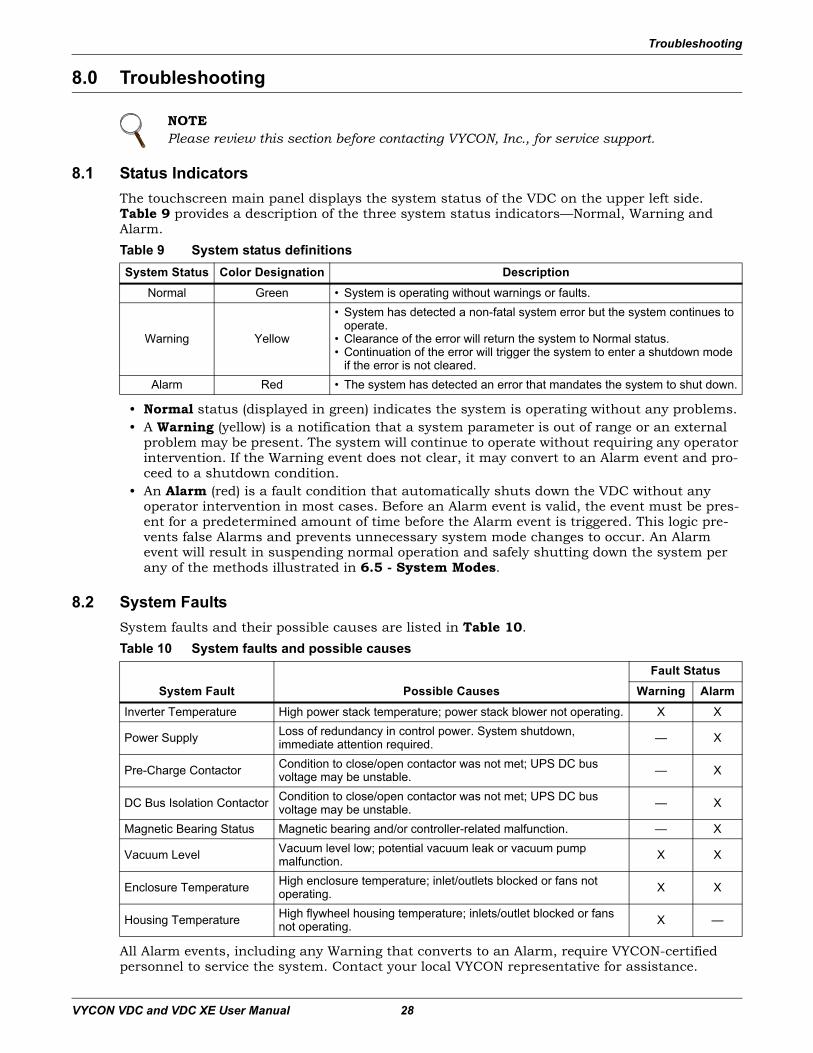
8.2 System FaultsSystem faults and their possible causes are listed in Table 10.
All Alarm events, including any Warning that converts to an Alarm, require VYCON-certified personnel to service the system. Contact your local VYCON representative for assistance.
NOTEPlease review this section before contacting VYCON, Inc., for service support.
Table 9 System status definitionsSystem Status Color Designation Description
Normal Green • System is operating without warnings or faults.
Warning Yellow
• System has detected a non-fatal system error but the system continues to operate.
• Clearance of the error will return the system to Normal status.• Continuation of the error will trigger the system to enter a shutdown mode
if the error is not cleared.Alarm Red • The system has detected an error that mandates the system to shut down.
Table 10 System faults and possible causes
System Fault Possible CausesFault Status
Warning AlarmInverter Temperature High power stack temperature; power stack blower not operating. X X
Power Supply Loss of redundancy in control power. System shutdown, immediate attention required. — X
Pre-Charge Contactor Condition to close/open contactor was not met; UPS DC bus voltage may be unstable. — X
DC Bus Isolation Contactor Condition to close/open contactor was not met; UPS DC bus voltage may be unstable. — X
Magnetic Bearing Status Magnetic bearing and/or controller-related malfunction. — X
Vacuum Level Vacuum level low; potential vacuum leak or vacuum pump malfunction. X X
Enclosure Temperature High enclosure temperature; inlet/outlets blocked or fans not operating. X X
Housing Temperature High flywheel housing temperature; inlets/outlet blocked or fans not operating. X —
Maintenance
VYCON VDC and VDC XE User Manual 29
9.0 Maintenance
9.1 Safety PrecautionsAbide by all safety precautions in this manual, paying particular attention to 1.0 - Important Safety Instructions, before performing maintenance on the VDC and associate equipment.
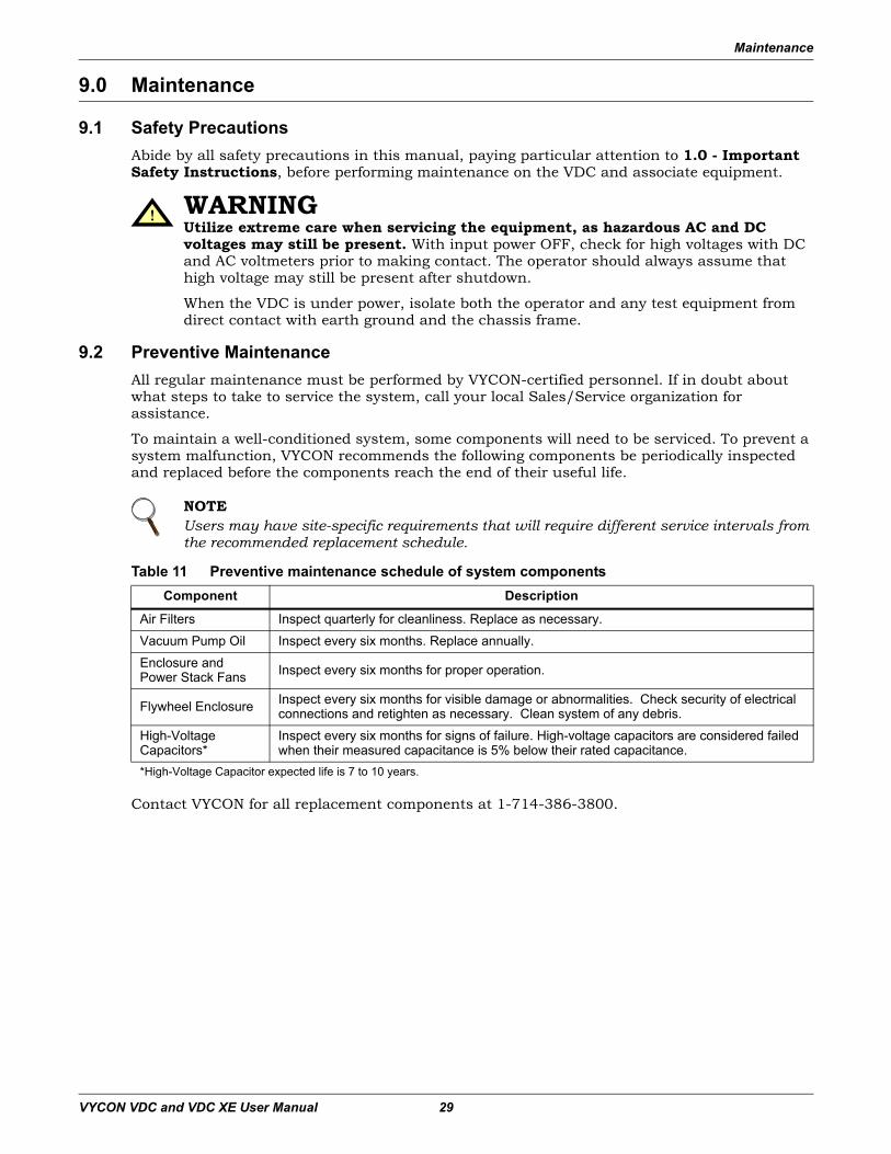
9.2 Preventive MaintenanceAll regular maintenance must be performed by VYCON-certified personnel. If in doubt about what steps to take to service the system, call your local Sales/Service organization for assistance.
To maintain a well-conditioned system, some components will need to be serviced. To prevent a system malfunction, VYCON recommends the following components be periodically inspected and replaced before the components reach the end of their useful life.
Contact VYCON for all replacement components at 1-714-386-3800.
! WARNINGUtilize extreme care when servicing the equipment, as hazardous AC and DC voltages may still be present. With input power OFF, check for high voltages with DC and AC voltmeters prior to making contact. The operator should always assume that high voltage may still be present after shutdown.
When the VDC is under power, isolate both the operator and any test equipment from direct contact with earth ground and the chassis frame.
NOTEUsers may have site-specific requirements that will require different service intervals from the recommended replacement schedule.
Table 11 Preventive maintenance schedule of system componentsComponent Description
Air Filters Inspect quarterly for cleanliness. Replace as necessary.
Vacuum Pump Oil Inspect every six months. Replace annually.
Enclosure and Power Stack Fans Inspect every six months for proper operation.
Flywheel Enclosure Inspect every six months for visible damage or abnormalities. Check security of electrical connections and retighten as necessary. Clean system of any debris.
High-Voltage Capacitors*
Inspect every six months for signs of failure. High-voltage capacitors are considered failed when their measured capacitance is 5% below their rated capacitance.
*High-Voltage Capacitor expected life is 7 to 10 years.
Technical Support
VYCON VDC and VDC XE User Manual 30
10.0 Technical Support
VYCON is dedicated to providing high-quality products to the owners and users of every VDC. Your VDC should operate free from trouble.
If you require maintenance support, spare parts or other technical assistance, please contact your local Sales/Service organization for assistance and have the following information available:
• Date Purchased
• Location
• System Model Number
• System Serial Number
• Interconnected UPS Manufacturer
• Interconnected UPS Model
Specifications
VYCON VDC and VDC XE User Manual 31
11.0 Specifications
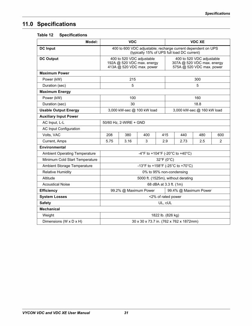
Table 12 Specifications Model: VDC VDC XE
DC Input 400 to 600 VDC adjustable; recharge current dependent on UPS(typically 15% of UPS full load DC current)
DC Output 400 to 520 VDC adjustable192A @ 520 VDC max. energy413A @ 520 VDC max. power
400 to 520 VDC adjustable307A @ 520 VDC max. energy575A @ 520 VDC max. power
Maximum PowerPower (kW) 215 300
Duration (sec) 5 5
Maximum EnergyPower (kW) 100 160
Duration (sec) 30 18.8
Usable Output Energy 3,000 kW-sec @ 100 kW load 3,000 kW-sec @ 160 kW load
Auxiliary Input PowerAC Input, L-L 50/60 Hz, 2-WIRE + GND
AC Input Configuration
Volts, VAC 208 380 400 415 440 480 600
Current, Amps 5.75 3.16 3 2.9 2.73 2.5 2
EnvironmentalAmbient Operating Temperature -4°F to +104°F (-20°C to +40°C)
Minimum Cold Start Temperature 32°F (0°C)
Ambient Storage Temperature -13°F to +158°F (-25°C to +70°C)
Relative Humidity 0% to 95% non-condensing
Altitude 5000 ft. (1525m), without derating
Acoustical Noise 68 dBA at 3.3 ft. (1m)
Efficiency 99.2% @ Maximum Power 99.4% @ Maximum Power
System Losses <2% of rated power
Safety UL, cUL
MechanicalWeight 1822 lb. (826 kg)
Dimensions (W x D x H) 30 x 30 x 73.7 in. (762 x 762 x 1872mm)
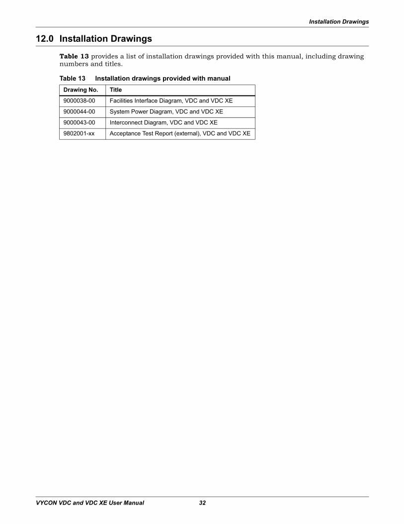
Installation Drawings
VYCON VDC and VDC XE User Manual 32
12.0 Installation Drawings
Table 13 provides a list of installation drawings provided with this manual, including drawing numbers and titles.
Table 13 Installation drawings provided with manualDrawing No. Title
9000038-00 Facilities Interface Diagram, VDC and VDC XE
9000044-00 System Power Diagram, VDC and VDC XE
9000043-00 Interconnect Diagram, VDC and VDC XE
9802001-xx Acceptance Test Report (external), VDC and VDC XE


![IA 1A Periodic Table of the Elements H He · Electron Configuration Electron Shells 1 IA 1A 1 2 3 ... [Xe]5d16s2 [Xe]4f15d16s2 [Xe]4f36s2 [Xe]4f46s2 [Xe]4f56s2 [Xe]4f66s2 [Xe]4f76s2](https://img.pdfslide.us/doc/110x75/5b6b1a407f8b9a9f1b8d06f3/ia-1a-periodic-table-of-the-elements-h-he-electron-configuration-electron-shells.jpg)
![Periodic Table Electron Configuration - BBG - 2015 · Electron Configuration 1s1 [Rn ... [Xe]5d16s2 [Xe]4f15d16s2 [Xe]4f36s2 [Xe]4f46s2 [Xe]4f56s2 [Xe]4f66s2 [Xe]4f76s2 [Xe ... Color](https://img.pdfslide.us/doc/110x75/5b6b1a407f8b9a9f1b8d06f2/periodic-table-electron-configuration-bbg-2015-electron-configuration-1s1.jpg)
![Symbol - 0.tqn.com · Xe Xenon 131.29 55 Cs ... Electron Configuration 1s1 [Rn]5f146d37s2 ... [Xe]5d16s2 [Xe]4f15d16s2 [Xe]4f36s2 [Xe]4f46s2 [Xe]4f56s2 [Xe]4f66s2 [Xe]4f76s2 [Xe](https://img.pdfslide.us/doc/110x75/5b6b1a407f8b9a9f1b8d06f4/symbol-0tqncom-xe-xenon-13129-55-cs-electron-configuration-1s1-rn5f146d37s2.jpg)