Embed Size (px)
Citation preview
26th INTERNATIONAL CONGRESS OF THE AERONAUTICAL SCIENCES
MULTIVARIABLE CONTROLLER DESIGN FOR ATRIMMABLE HORIZONTAL
STABILIZER ACTUATOR WITH TWO PRIMARY LOAD PATHS
Nils Wachendorf, Frank Thielecke, Udo Carl, Timo PeHamburg University of Technology, Institute of Aircraft Systems Engineering
Keywords: THSA, H∞ Controller Design, Mixed Sensitivity Design
Abstract
A novel drive concept for the Trimmable Hor-izontal Stabilizer Actuator (THSA) is based ontwo ballscrews operating in parallel which movethe stabilizer to adjust the angle of attack ofthe horizontal tailplane. The positions of theballscrew nuts are mechanically synchronizedbecause the two installed differential gearboxesuniformly distribute the mechanical power to thetwo drive chains independently of the operationalcondition. A H∞ controller design is employedto control the rotational speed of the hydraulicmotors. The resulting multivariable speed con-troller is implemented into the nonlinear simu-lation model, the simulation results of which arevalidated through measurements at the THSA testrig. The simulation results of the multivariableclosed loop are compared with the results ob-tained from a closed loop with cascade structure.
1 Introduction
The pitch trim of transport aircraft is usually con-trolled by an adjustable horizontal tailplane. Asprescribed by the airworthiness requirements, allsafety critical load bearing components of a civiltransport airplane are designed to have two inde-pendent mechanical load paths. Thus, there mustexist two mechanical load paths between the hor-izontal tailplane and the aircrafts fuselage struc-ture. Today’s Trimmable Horizontal StabilizerActuator uses in normal operation only one loadpath (e.g. one ballscrew). In case of failure (dis-
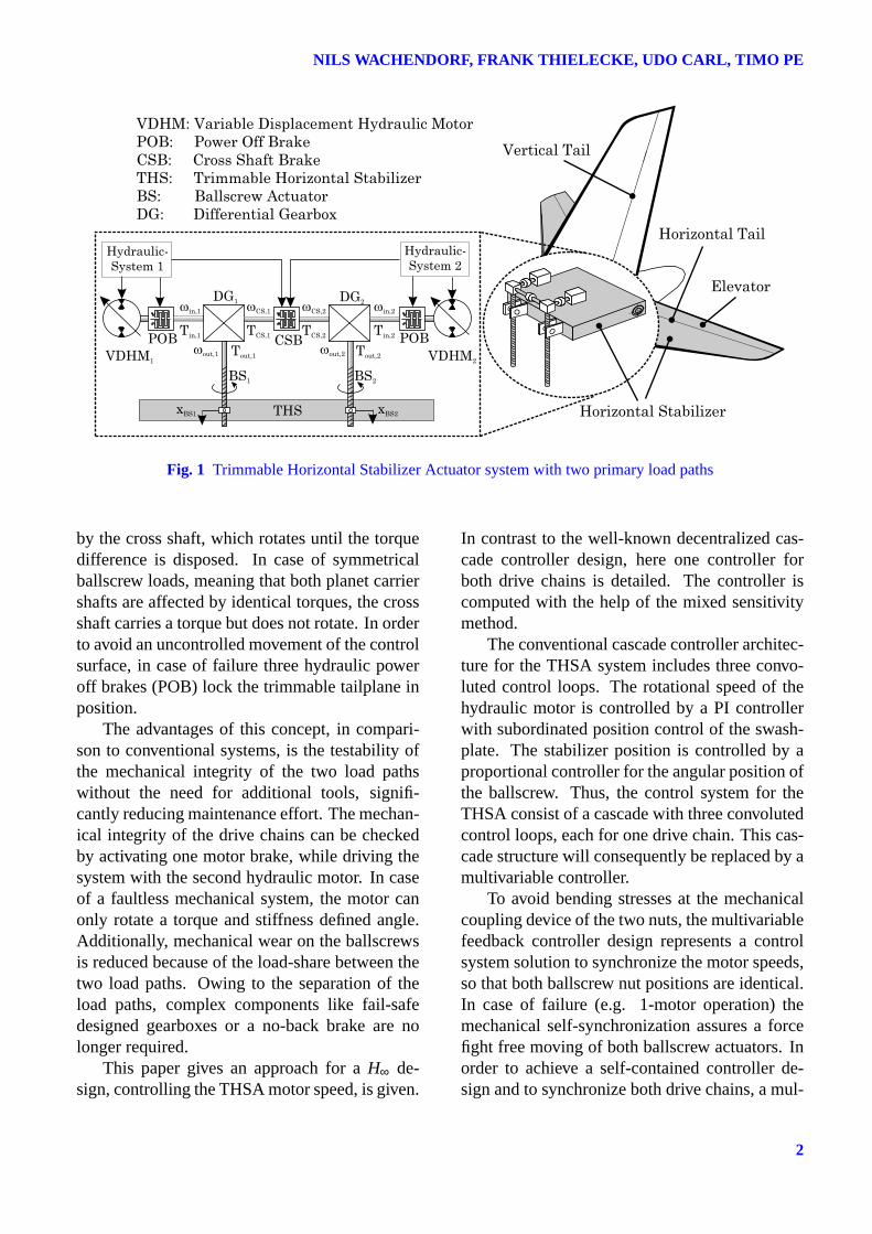
connection of the first load path/ballscrew) thesecondary load path (e.g. a tie rod, which is inte-grated in the hollow ballscrew) prevents a com-plete disconnection and an uncontrolled move-ment of the horizontal stabilizer. Consequently,the second load path is normally unloaded. Com-pared to a conventional THSA architecture, theconcept presented here incorporates two active-parallel operating load paths to move the stabi-lizer (cp. figure 1). Active-parallel in this casemeans the appearing airload is shared betweenthe two ballscrew actuators. These comprise sin-gle load path ballscrew actuators (BS), displacingthe trimmable horizontal stabilizer (THS). Theactuation system consists of two differential gear-boxes with three shafts each. The arrangementand the mechanical coupling of the two differ-ential gears ensure a synchronization of the twodrive chains. Each ballscrew is connected tothe planet carrier shaft of a differential gearbox(DG). One input shaft of the differential gearboxis mounted to a variable displacement hydraulicmotor (VDHM). The remaining inputs of the dif-ferential gearboxes are connected by a so-calledcross shaft (CS). This arrangement enables anauto-synchronization of the ballscrew positionsprecluding force-fight. The two ballscrew nutsare mechanically coupled through the support-ing elements of the horizontal stabilizer. Ow-ing to the stationary gear ratio of the differentialgears and the sum of moments at the shafts ofthe differential gearboxes, a torque difference be-tween the two drive chains will be compensated
1
NILS WACHENDORF, FRANK THIELECKE, UDO CARL, TIMO PE
Fig. 1 Trimmable Horizontal Stabilizer Actuator system with two primary load paths
by the cross shaft, which rotates until the torquedifference is disposed. In case of symmetricalballscrew loads, meaning that both planet carriershafts are affected by identical torques, the crossshaft carries a torque but does not rotate. In orderto avoid an uncontrolled movement of the controlsurface, in case of failure three hydraulic poweroff brakes (POB) lock the trimmable tailplane inposition.
The advantages of this concept, in compari-son to conventional systems, is the testability ofthe mechanical integrity of the two load pathswithout the need for additional tools, signifi-cantly reducing maintenance effort. The mechan-ical integrity of the drive chains can be checkedby activating one motor brake, while driving thesystem with the second hydraulic motor. In caseof a faultless mechanical system, the motor canonly rotate a torque and stiffness defined angle.Additionally, mechanical wear on the ballscrewsis reduced because of the load-share between thetwo load paths. Owing to the separation of theload paths, complex components like fail-safedesigned gearboxes or a no-back brake are nolonger required.
This paper gives an approach for aH∞ de-sign, controlling the THSA motor speed, is given.
In contrast to the well-known decentralized cas-cade controller design, here one controller forboth drive chains is detailed. The controller iscomputed with the help of the mixed sensitivitymethod.
The conventional cascade controller architec-ture for the THSA system includes three convo-luted control loops. The rotational speed of thehydraulic motor is controlled by a PI controllerwith subordinated position control of the swash-plate. The stabilizer position is controlled by aproportional controller for the angular position ofthe ballscrew. Thus, the control system for theTHSA consist of a cascade with three convolutedcontrol loops, each for one drive chain. This cas-cade structure will consequently be replaced by amultivariable controller.
To avoid bending stresses at the mechanicalcoupling device of the two nuts, the multivariablefeedback controller design represents a controlsystem solution to synchronize the motor speeds,so that both ballscrew nut positions are identical.In case of failure (e.g. 1-motor operation) themechanical self-synchronization assures a forcefight free moving of both ballscrew actuators. Inorder to achieve a self-contained controller de-sign and to synchronize both drive chains, a mul-
2
Multivariable Controller Design for a Trimmable HorizontalStabilizer Actuator with Two Primary Load Paths
tivariable system (MIMO) approach is chosen.The obtained controller is implemented into
the nonlinear simulation model and simulationresults are compared to the cascade controller ar-chitecture. The simulations are validated by mea-surements at the THSA test rig, which was set upat the Institute of Aircraft Systems Engineering.
2 THSA System Structure
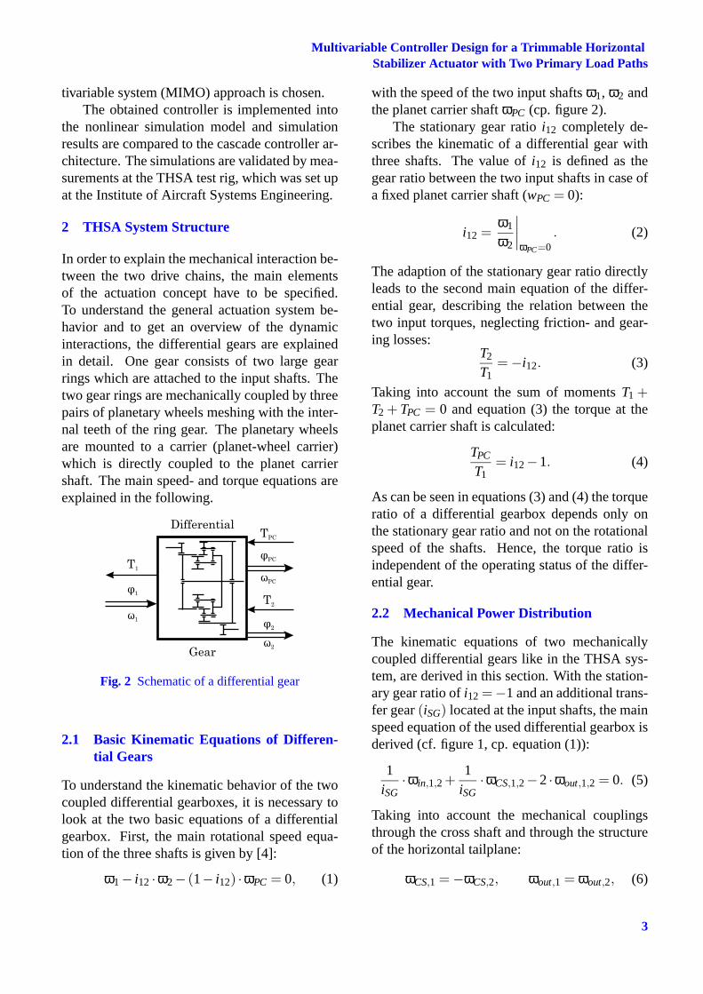
In order to explain the mechanical interaction be-tween the two drive chains, the main elementsof the actuation concept have to be specified.To understand the general actuation system be-havior and to get an overview of the dynamicinteractions, the differential gears are explainedin detail. One gear consists of two large gearrings which are attached to the input shafts. Thetwo gear rings are mechanically coupled by threepairs of planetary wheels meshing with the inter-nal teeth of the ring gear. The planetary wheelsare mounted to a carrier (planet-wheel carrier)which is directly coupled to the planet carriershaft. The main speed- and torque equations areexplained in the following.
Fig. 2 Schematic of a differential gear
2.1 Basic Kinematic Equations of Differen-tial Gears
To understand the kinematic behavior of the twocoupled differential gearboxes, it is necessary tolook at the two basic equations of a differentialgearbox. First, the main rotational speed equa-tion of the three shafts is given by [4]:
ω1− i12 ·ω2− (1− i12) ·ωPC = 0, (1)
with the speed of the two input shaftsω1, ω2 andthe planet carrier shaftωPC (cp. figure 2).
The stationary gear ratioi12 completely de-scribes the kinematic of a differential gear withthree shafts. The value ofi12 is defined as thegear ratio between the two input shafts in case ofa fixed planet carrier shaft (wPC = 0):
i12 =ω1
ω2
∣
∣
∣
∣
ωPC=0. (2)
The adaption of the stationary gear ratio directlyleads to the second main equation of the differ-ential gear, describing the relation between thetwo input torques, neglecting friction- and gear-ing losses:
T2
T1= −i12. (3)
Taking into account the sum of momentsT1 +T2 + TPC = 0 and equation (3) the torque at theplanet carrier shaft is calculated:
TPC
T1= i12−1. (4)
As can be seen in equations (3) and (4) the torqueratio of a differential gearbox depends only onthe stationary gear ratio and not on the rotationalspeed of the shafts. Hence, the torque ratio isindependent of the operating status of the differ-ential gear.
2.2 Mechanical Power Distribution
The kinematic equations of two mechanicallycoupled differential gears like in the THSA sys-tem, are derived in this section. With the station-ary gear ratio ofi12 =−1 and an additional trans-fer gear(iSG) located at the input shafts, the mainspeed equation of the used differential gearbox isderived (cf. figure 1, cp. equation (1)):
1iSG
·ωin,1,2 +1
iSG·ωCS,1,2−2·ωout,1,2 = 0. (5)
Taking into account the mechanical couplingsthrough the cross shaft and through the structureof the horizontal tailplane:
ωCS,1 = −ωCS,2, ωout,1 = ωout,2, (6)
3

NILS WACHENDORF, FRANK THIELECKE, UDO CARL, TIMO PE
Fig. 3 Cascade controller structure of one drive chain of the THSA system
the superposition of the main speed equation (5)of both differential gearboxes results in:
1iSG
·ωin,1 + 1iSG
·ωCS,1−2·ωout,1 = . . .
. . .
1iSG
·ωin,2−1
iSG·ωCS,1−2·ωout,1
(7)
⇒ 2·ωCS,1 = ωin,2−ωin,1. (8)
The result (eqn. (8)) shows that the cross shaftonly starts to rotate in case of different motor in-put speeds. The rotational speed of the planet car-rier shaft depends on the motor input speedωin
and the cross shaft speedωCS (eqn. (5)):
ωout =1
2iSG· (ωin +ωCS) . (9)
In case of fixed motor shafts, either by no move-ment commanded or activated power off brakesωin = ωin,1 = ωin,2 = 0, the cross shaft speed isgiven by equation (8):
ωCS,1 = ωCS,2 = 0. (10)
Thus, the mechanical coupling through the crossshaft ensures a fixation of the horizontal stabilizerwithout using the cross shaft brake.
Using the torque equations (3) and (4) andconsidering the stationary gear ratioi12 =−1 andthe gear ratio of the spur geariSG, the torque re-lations of the THSA are calculated (cf. figure 1):
TCS
Tin,1= 1,
Tout,1
Tin,1=
Tout,1
TCS= −2· iSG. (11)
2.3 Cascade Control Concept
The cascade control concept of the THSA is com-posed out of three stand-alone control loops. Thecascade concept is sequently set up of these threeloops (cf. figure 3). The first (ϕSP1) and thesecond control loop (ωHM1) are used to controlthe hydraulic motor rotational speed. The mo-tor torque depends on the displacement volumeof the hydraulic motor. The displacement is var-ied by pivoting the swashplate. The innermostcontrol loop is closed by the measured swash-plate angle (ϕSP1). To control the motor speed(ωHM1) a second control loop is needed which isclosed with a PI controller. The PI controller out-put signal is used as input signal (ωHMC) for theswashplate angular position control loop. To con-trol the horizontal stabilizer position (ϕTHS), thethird control loop feeds back the angular positionof the ballscrew actuator (ϕBS1). The output sig-nal of this superior loop is used as input signal(ωHMC) for the motor speed control loop.
The angle of attack of the horizontal stabi-lizer results from the fixed pitch of the ballscrewsand the lever arm of the stabilizer. For eachdrive chain (motor, gear, shaft transmissionballscrew) a set of three proportional controllergains (PBS,PHM,PSP) and one gain for the integralpart of the speed controller (IHM) are evaluated.Therefore, a decentralized control structure is ob-tained with one stand-alone cascade structure foreach drive chain (cp. figure 4). The advantage of
4
Multivariable Controller Design for a Trimmable HorizontalStabilizer Actuator with Two Primary Load Paths
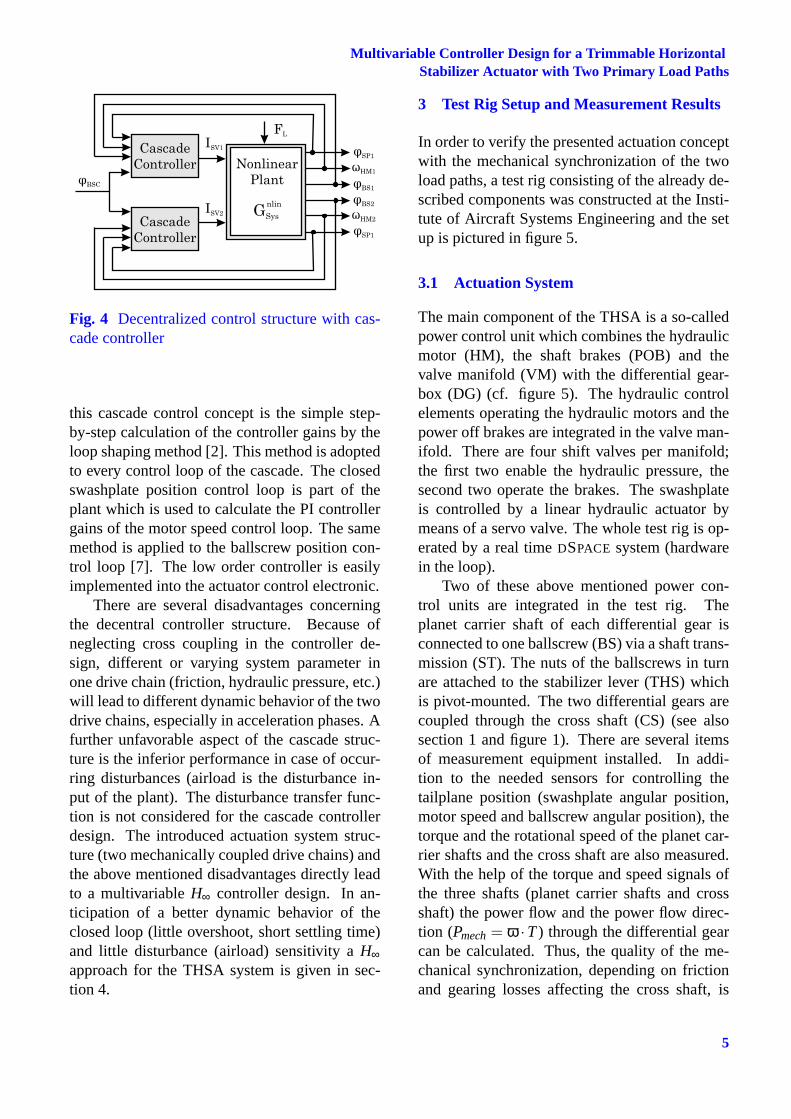
Fig. 4 Decentralized control structure with cas-cade controller
this cascade control concept is the simple step-by-step calculation of the controller gains by theloop shaping method [2]. This method is adoptedto every control loop of the cascade. The closedswashplate position control loop is part of theplant which is used to calculate the PI controllergains of the motor speed control loop. The samemethod is applied to the ballscrew position con-trol loop [7]. The low order controller is easilyimplemented into the actuator control electronic.
There are several disadvantages concerningthe decentral controller structure. Because ofneglecting cross coupling in the controller de-sign, different or varying system parameter inone drive chain (friction, hydraulic pressure, etc.)will lead to different dynamic behavior of the twodrive chains, especially in acceleration phases. Afurther unfavorable aspect of the cascade struc-ture is the inferior performance in case of occur-ring disturbances (airload is the disturbance in-put of the plant). The disturbance transfer func-tion is not considered for the cascade controllerdesign. The introduced actuation system struc-ture (two mechanically coupled drive chains) andthe above mentioned disadvantages directly leadto a multivariableH∞ controller design. In an-ticipation of a better dynamic behavior of theclosed loop (little overshoot, short settling time)and little disturbance (airload) sensitivity aH∞approach for the THSA system is given in sec-tion 4.
3 Test Rig Setup and Measurement Results
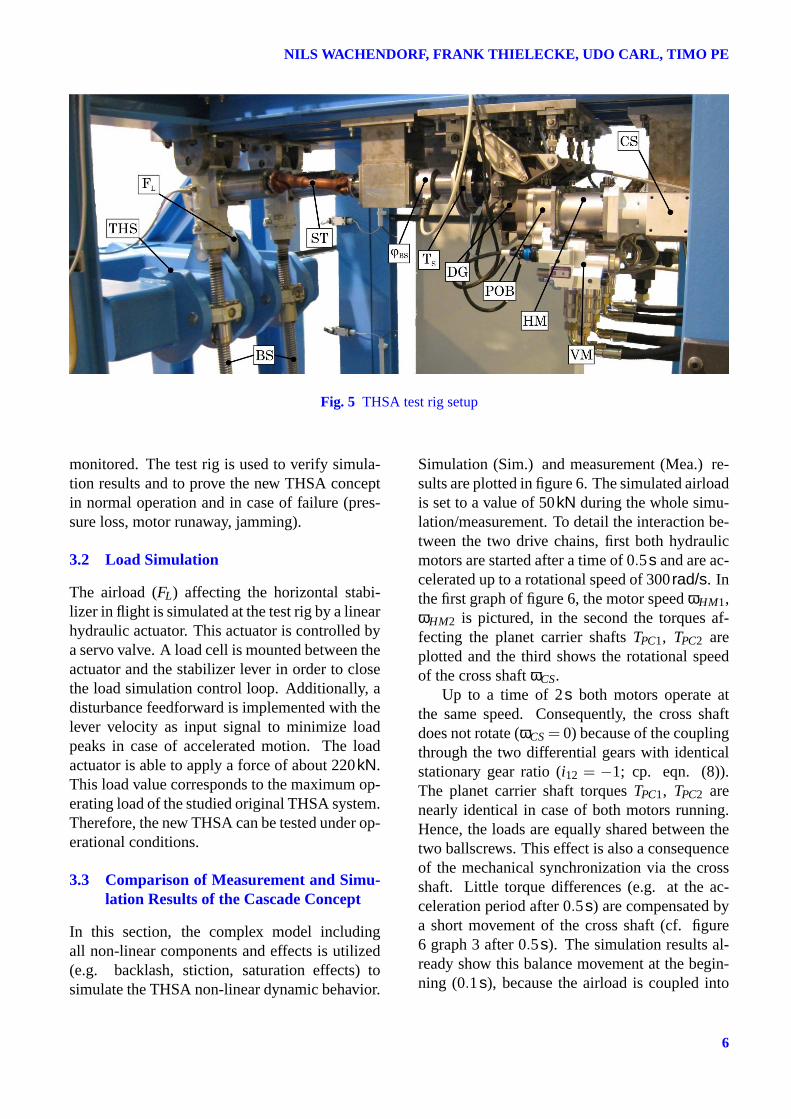
In order to verify the presented actuation conceptwith the mechanical synchronization of the twoload paths, a test rig consisting of the already de-scribed components was constructed at the Insti-tute of Aircraft Systems Engineering and the setup is pictured in figure 5.
3.1 Actuation System
The main component of the THSA is a so-calledpower control unit which combines the hydraulicmotor (HM), the shaft brakes (POB) and thevalve manifold (VM) with the differential gear-box (DG) (cf. figure 5). The hydraulic controlelements operating the hydraulic motors and thepower off brakes are integrated in the valve man-ifold. There are four shift valves per manifold;the first two enable the hydraulic pressure, thesecond two operate the brakes. The swashplateis controlled by a linear hydraulic actuator bymeans of a servo valve. The whole test rig is op-erated by a real timeDSPACE system (hardwarein the loop).
Two of these above mentioned power con-trol units are integrated in the test rig. Theplanet carrier shaft of each differential gear isconnected to one ballscrew (BS) via a shaft trans-mission (ST). The nuts of the ballscrews in turnare attached to the stabilizer lever (THS) whichis pivot-mounted. The two differential gears arecoupled through the cross shaft (CS) (see alsosection 1 and figure 1). There are several itemsof measurement equipment installed. In addi-tion to the needed sensors for controlling thetailplane position (swashplate angular position,motor speed and ballscrew angular position), thetorque and the rotational speed of the planet car-rier shafts and the cross shaft are also measured.With the help of the torque and speed signals ofthe three shafts (planet carrier shafts and crossshaft) the power flow and the power flow direc-tion (Pmech= ω ·T) through the differential gearcan be calculated. Thus, the quality of the me-chanical synchronization, depending on frictionand gearing losses affecting the cross shaft, is
5
NILS WACHENDORF, FRANK THIELECKE, UDO CARL, TIMO PE
Fig. 5 THSA test rig setup
monitored. The test rig is used to verify simula-tion results and to prove the new THSA conceptin normal operation and in case of failure (pres-sure loss, motor runaway, jamming).
3.2 Load Simulation
The airload (FL) affecting the horizontal stabi-lizer in flight is simulated at the test rig by a linearhydraulic actuator. This actuator is controlled bya servo valve. A load cell is mounted between theactuator and the stabilizer lever in order to closethe load simulation control loop. Additionally, adisturbance feedforward is implemented with thelever velocity as input signal to minimize loadpeaks in case of accelerated motion. The loadactuator is able to apply a force of about 220kN.This load value corresponds to the maximum op-erating load of the studied original THSA system.Therefore, the new THSA can be tested under op-erational conditions.
3.3 Comparison of Measurement and Simu-lation Results of the Cascade Concept
In this section, the complex model includingall non-linear components and effects is utilized(e.g. backlash, stiction, saturation effects) tosimulate the THSA non-linear dynamic behavior.
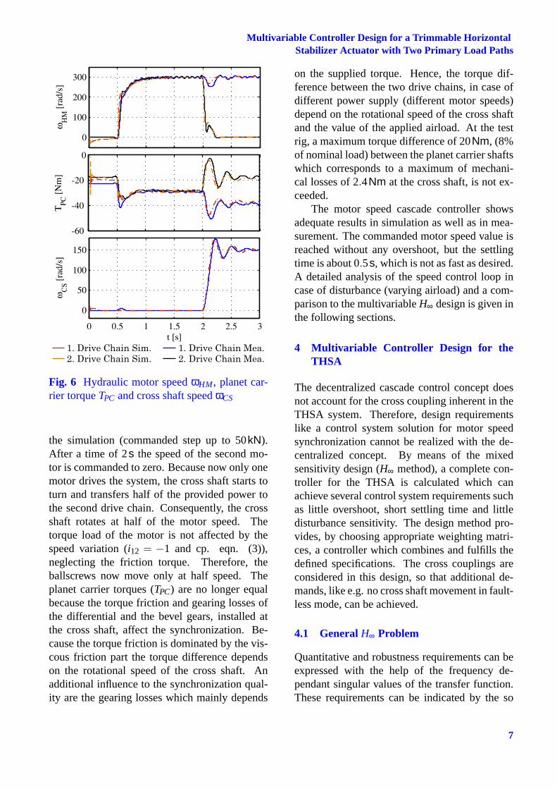
Simulation (Sim.) and measurement (Mea.) re-sults are plotted in figure 6. The simulated airloadis set to a value of 50kN during the whole simu-lation/measurement. To detail the interaction be-tween the two drive chains, first both hydraulicmotors are started after a time of 0.5s and are ac-celerated up to a rotational speed of 300rad/s. Inthe first graph of figure 6, the motor speedωHM1,ωHM2 is pictured, in the second the torques af-fecting the planet carrier shaftsTPC1, TPC2 areplotted and the third shows the rotational speedof the cross shaftωCS.
Up to a time of 2s both motors operate atthe same speed. Consequently, the cross shaftdoes not rotate (ωCS= 0) because of the couplingthrough the two differential gears with identicalstationary gear ratio (i12 = −1; cp. eqn. (8)).The planet carrier shaft torquesTPC1, TPC2 arenearly identical in case of both motors running.Hence, the loads are equally shared between thetwo ballscrews. This effect is also a consequenceof the mechanical synchronization via the crossshaft. Little torque differences (e.g. at the ac-celeration period after 0.5s) are compensated bya short movement of the cross shaft (cf. figure6 graph 3 after 0.5s). The simulation results al-ready show this balance movement at the begin-ning (0.1s), because the airload is coupled into
6
Multivariable Controller Design for a Trimmable HorizontalStabilizer Actuator with Two Primary Load Paths
Fig. 6 Hydraulic motor speedωHM, planet car-rier torqueTPC and cross shaft speedωCS
the simulation (commanded step up to 50kN).After a time of 2s the speed of the second mo-tor is commanded to zero. Because now only onemotor drives the system, the cross shaft starts toturn and transfers half of the provided power tothe second drive chain. Consequently, the crossshaft rotates at half of the motor speed. Thetorque load of the motor is not affected by thespeed variation (i12 = −1 and cp. eqn. (3)),neglecting the friction torque. Therefore, theballscrews now move only at half speed. Theplanet carrier torques (TPC) are no longer equalbecause the torque friction and gearing losses ofthe differential and the bevel gears, installed atthe cross shaft, affect the synchronization. Be-cause the torque friction is dominated by the vis-cous friction part the torque difference dependson the rotational speed of the cross shaft. Anadditional influence to the synchronization qual-ity are the gearing losses which mainly depends
on the supplied torque. Hence, the torque dif-ference between the two drive chains, in case ofdifferent power supply (different motor speeds)depend on the rotational speed of the cross shaftand the value of the applied airload. At the testrig, a maximum torque difference of 20Nm, (8%of nominal load) between the planet carrier shaftswhich corresponds to a maximum of mechani-cal losses of 2.4Nm at the cross shaft, is not ex-ceeded.
The motor speed cascade controller showsadequate results in simulation as well as in mea-surement. The commanded motor speed value isreached without any overshoot, but the settlingtime is about 0.5s, which is not as fast as desired.A detailed analysis of the speed control loop incase of disturbance (varying airload) and a com-parison to the multivariableH∞ design is given inthe following sections.
4 Multivariable Controller Design for theTHSA
The decentralized cascade control concept doesnot account for the cross coupling inherent in theTHSA system. Therefore, design requirementslike a control system solution for motor speedsynchronization cannot be realized with the de-centralized concept. By means of the mixedsensitivity design (H∞ method), a complete con-troller for the THSA is calculated which canachieve several control system requirements suchas little overshoot, short settling time and littledisturbance sensitivity. The design method pro-vides, by choosing appropriate weighting matri-ces, a controller which combines and fulfills thedefined specifications. The cross couplings areconsidered in this design, so that additional de-mands, like e.g. no cross shaft movement in fault-less mode, can be achieved.
4.1 General H∞ Problem
Quantitative and robustness requirements can beexpressed with the help of the frequency de-pendant singular values of the transfer function.These requirements can be indicated by the so
7
NILS WACHENDORF, FRANK THIELECKE, UDO CARL, TIMO PE
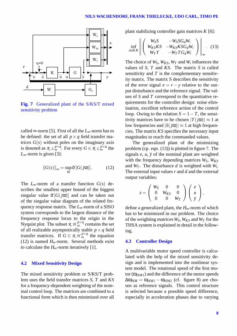
Fig. 7 Generalized plant of the S/KS/T mixedsensitivity problem
called∞-norm [5]. First of all theL∞-norm has tobe defined: the set of allp×q field transfer ma-tricesG(s) without poles on the imaginary axisis denoted asR L p×q
∞ . For everyG∈ R L p×q∞ the
L∞-norm is given [3]:
‖G(s)‖∞ = supω
σ [G( jω)]. (12)
The L∞-norm of a transfer functionG(s) de-scribes the smallest upper bound of the biggestsingular valueσ [G( jω)] and can be taken outof the singular value diagram of the related fre-quency response matrix. TheL∞-norm of a SISOsystem corresponds to the largest distance of thefrequency response locus to the origin in theNyquist plot. The subsetR H p×q
∞ contains the setof all realizable asymptotically stablep×q fieldtransfer matrices. IfG ∈ R H
p×q∞ the equation
(12) is namedH∞-norm. Several methods existto calculate theH∞-norm iteratively [1].
4.2 Mixed Sensitivity Design
The mixed sensitivity problem or S/KS/T prob-lem uses the field transfer matricesS, T andKSfor a frequency-dependent weighting of the nom-inal control loop. The matrices are combined to afunctional form which is then minimized over all
plant stabilizing controller gain matricesK [6]:
infstab.K
∥
∥
∥
∥
∥
∥
WSS −WSSGdWi
WKSKS −WKSKSGdWi
WTT −WTTGdWi
∥
∥
∥
∥
∥
∥
∞
. (13)
The choice ofWS, WKS, WT andWi influences thevalues ofS, T and KS. The matrixS is calledsensitivity andT is the complementary sensitiv-ity matrix. The matrix S describes the sensitivityof the error signale = r − y relative to the out-put disturbance and the reference signal. The val-ues ofSandT correspond to the quantitative re-quirements for the controller design: noise elim-ination, excellent reference action of the controlloop. Owing to the relationS= 1−T, the sensi-tivity matrices have to be chosen|T( jω)| ≈ 1 atlow frequencies and|S( jω)| ≈ 1 at high frequen-cies. The matrixKSspecifies the necessary inputmagnitudes to reach the commanded values.
The generalized plant of the minimizingproblem (cp. eqn. (13)) is plotted in figure 7. Thesignalse, u, y of the nominal plant are weightedwith the frequency depending matricesWS, WKS
andWT . The disturbanced is weighted withWi.The external input valuesr andd and the externaloutput variables:
z=
WS 0 00 WKS 00 0 WT
euy
,
define a generalized plant, theH∞-norm of whichhas to be minimized in our problem. The choiceof the weighting matricesWS, WKS andWT for theTHSA system is explained in detail in the follow-ing.
4.3 Controller Design
A multivariable motor speed controller is calcu-lated with the help of the mixed sensitivity de-sign and is implemented into the nonlinear sys-tem model. The rotational speed of the first mo-tor (ωHM1) and the difference of the motor speeds∆ωHM = ωHM1 −ωHM2 (cf. figure 8) are cho-sen as reference signals. This control structureis selected because a possible speed difference,especially in acceleration phases due to varying
8
Multivariable Controller Design for a Trimmable HorizontalStabilizer Actuator with Two Primary Load Paths
Fig. 8 Control loop structure of theH∞ approach
system parameters in one drive chain (hydraulicpressure, inertia, friction), will be compensatedby a feedback of∆ω.
A linear system model of the THSA is de-signed in order to be able to calculate the gener-alized plant for the mixed sensitivity design. Thelinear model is analytically set up to minimizerounding errors especially when calculating theobservability and controllability of the system.The THSA is fully controllable and all signalsneeded for the control loop are measured. Fur-thermore, the analytical linear model is used toidentify the model uncertainties with significantinfluence on the dynamic behavior. This infor-mation is used in a continuative robust controllerdesign with norm bounded uncertainties. For thecontroller design, a full rank approach is realizedwith a first order low pass filter characteristic ofthe weighting matrixWS:
WS =
sMS,i
+ωS,i
s+ωS,i · εS,i· I , with i = 1, . . . ,n, (14)
and a first order high pass filter characteristic ofWT [8]:
WT =s+
ωT,iMT,i
s· εT,i +ωT,i· I , with i = 1, . . . ,n, (15)
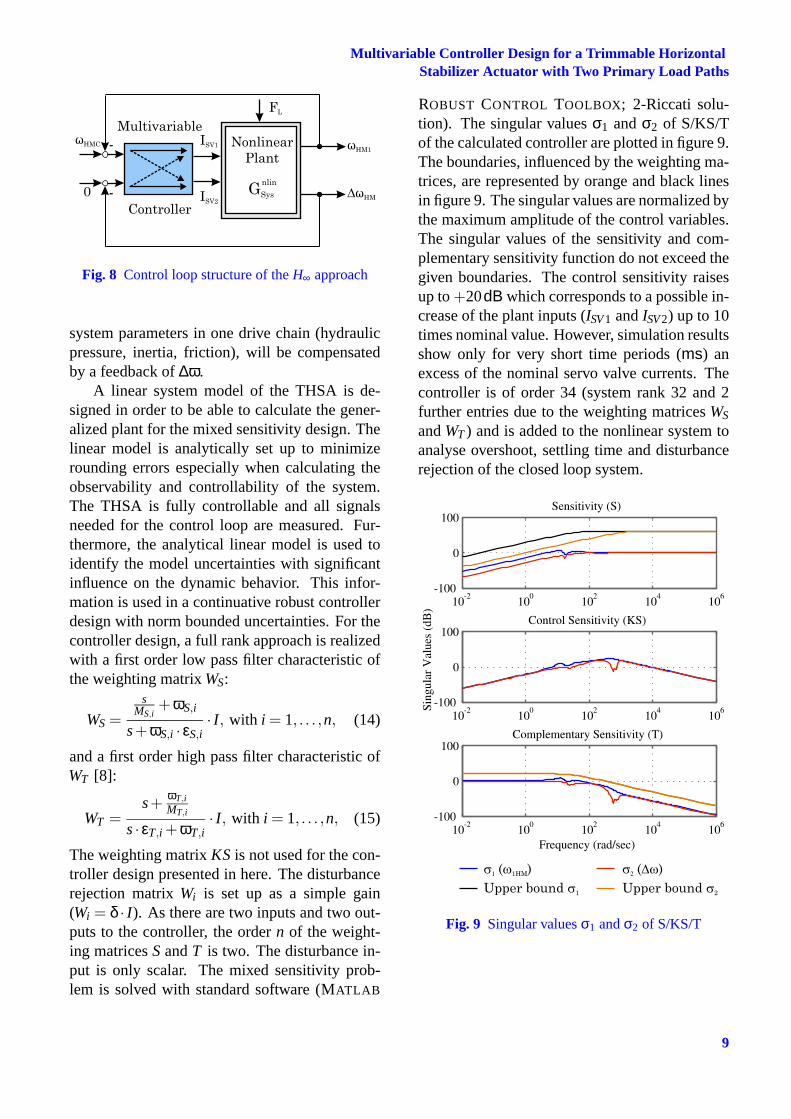
The weighting matrixKS is not used for the con-troller design presented in here. The disturbancerejection matrixWi is set up as a simple gain(Wi = δ · I ). As there are two inputs and two out-puts to the controller, the ordern of the weight-ing matricesSandT is two. The disturbance in-put is only scalar. The mixed sensitivity prob-lem is solved with standard software (MATLAB
ROBUST CONTROL TOOLBOX; 2-Riccati solu-tion). The singular valuesσ1 andσ2 of S/KS/Tof the calculated controller are plotted in figure 9.The boundaries, influenced by the weighting ma-trices, are represented by orange and black linesin figure 9. The singular values are normalized bythe maximum amplitude of the control variables.The singular values of the sensitivity and com-plementary sensitivity function do not exceed thegiven boundaries. The control sensitivity raisesup to+20dB which corresponds to a possible in-crease of the plant inputs (ISV1 andISV2) up to 10times nominal value. However, simulation resultsshow only for very short time periods (ms) anexcess of the nominal servo valve currents. Thecontroller is of order 34 (system rank 32 and 2further entries due to the weighting matricesWS
andWT) and is added to the nonlinear system toanalyse overshoot, settling time and disturbancerejection of the closed loop system.
Fig. 9 Singular valuesσ1 andσ2 of S/KS/T
9
NILS WACHENDORF, FRANK THIELECKE, UDO CARL, TIMO PE
5 Comparison of the Cascade and the Multi-variable Controller
In order to compare a set point profile for the sim-ulation and measurement results is defined: themotor speed is commanded toω = 300rad/s af-ter 0.5s. After a time of 2.5s, a disturbance stepto 100kN (50 % of nominal loads) is induced toanalyse the disturbance rejection.
5.1 Reference and Disturbance Reactions
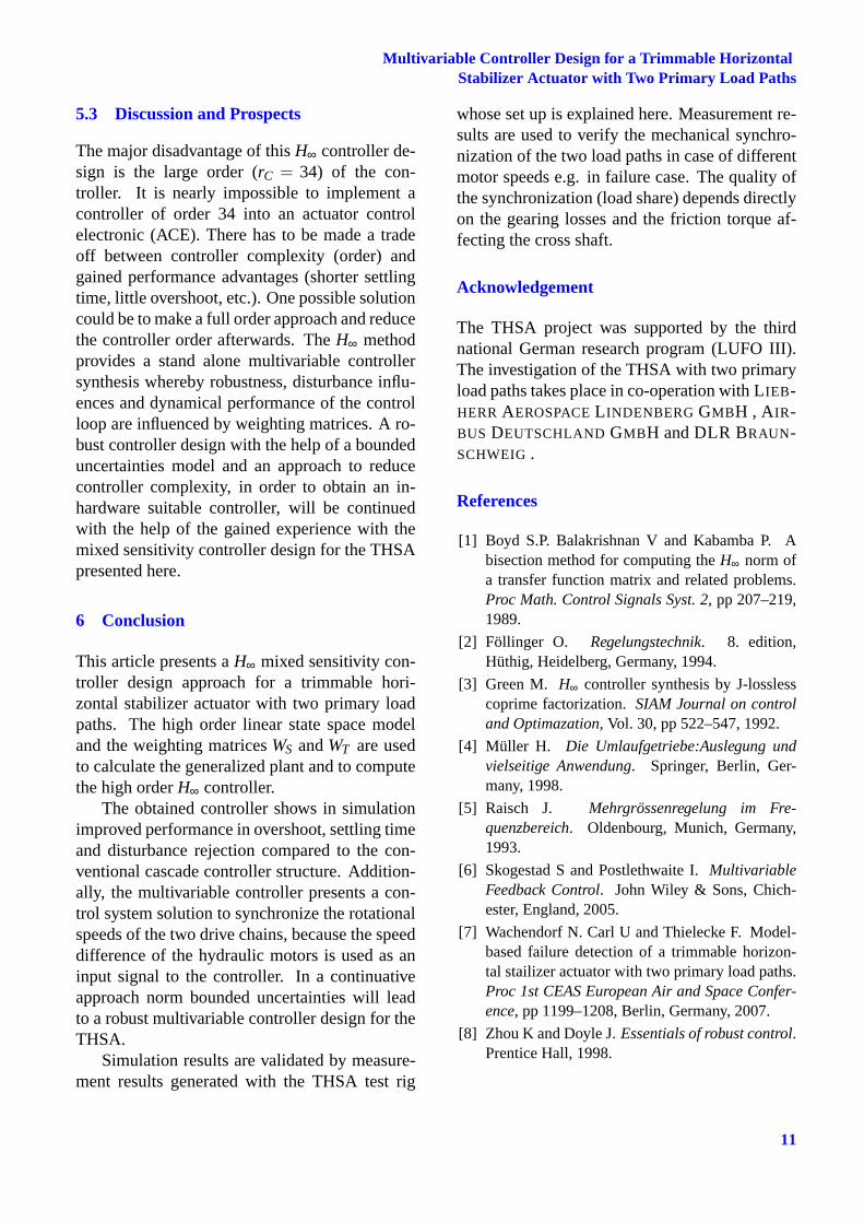
Both, the cascade step response and the multivariable controller step response of the motorspeed are plotted in figure 10. The step responseof the H∞ controller design reaches the finalvalue faster (ts,H∞ = 0.64s, ts,c = 1.6s) with onlylittle overshoot (ωmax,H∞ = 302rad/s, ωmax,C =314rad/s). The speed undershoot in case ofapplied airload is smaller, using theH∞ con-troller design (ωmin,H∞ = 200rad/s, ωmin,C =148rad/s). Moreover the transient time of theH∞ controller is shorter than the transient time ofthe cascade (tt,H∞ = 0.13s, tt,c = 1.04s). Con-cluding, the multivariable controller combines ashorter settling time with equivalent overshootand a better disturbance rejection, compared tothe cascade controller concept. Additionally, thecontrol of the motor speed difference yields syn-chronization of the drive chains in case of differ-ing system parameters.
Fig. 10 Simulation results of the motor speedωHM of the cascade and multivariable controllerconcept
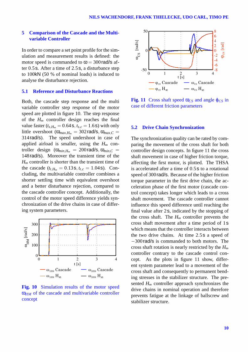
Fig. 11 Cross shaft speedωCS and angleϕCS incase of different friction parameters
5.2 Drive Chain Synchronization
The synchronization quality can be rated by com-paring the movement of the cross shaft for bothcontroller design concepts. In figure 11 the crossshaft movement in case of higher friction torque,affecting the first motor, is plotted. The THSAis accelerated after a time of 0.5s to a rotationalspeed of 300rad/s. Because of the higher frictiontorque parameter in the first drive chain, the ac-celeration phase of the first motor (cascade con-trol concept) takes longer which leads to a crossshaft movement. The cascade controller cannotinfluence this speed difference until reaching thefinal value after 2s, indicated by the stopping ofthe cross shaft. TheH∞ controller prevents thecross shaft movement after a time period of 1swhich means that the controller interacts betweenthe two drive chains. At time 2.5s a speed of−300rad/s is commanded to both motors. Thecross shaft rotation is nearly restricted by theH∞controller contrary to the cascade control con-cept. As the plots in figure 11 show, differ-ent system parameter lead to a movement of thecross shaft and consequently to permanent bend-ing stresses in the stabilizer structure. The pre-sentedH∞ controller approach synchronizes thedrive chains in nominal operation and thereforeprevents fatigue at the linkage of ballscrew andstabilizer structure.
10
Multivariable Controller Design for a Trimmable HorizontalStabilizer Actuator with Two Primary Load Paths
5.3 Discussion and Prospects
The major disadvantage of thisH∞ controller de-sign is the large order (rC = 34) of the con-troller. It is nearly impossible to implement acontroller of order 34 into an actuator controlelectronic (ACE). There has to be made a tradeoff between controller complexity (order) andgained performance advantages (shorter settlingtime, little overshoot, etc.). One possible solutioncould be to make a full order approach and reducethe controller order afterwards. TheH∞ methodprovides a stand alone multivariable controllersynthesis whereby robustness, disturbance influ-ences and dynamical performance of the controlloop are influenced by weighting matrices. A ro-bust controller design with the help of a boundeduncertainties model and an approach to reducecontroller complexity, in order to obtain an in-hardware suitable controller, will be continuedwith the help of the gained experience with themixed sensitivity controller design for the THSApresented here.
6 Conclusion
This article presents aH∞ mixed sensitivity con-troller design approach for a trimmable hori-zontal stabilizer actuator with two primary loadpaths. The high order linear state space modeland the weighting matricesWS andWT are usedto calculate the generalized plant and to computethe high orderH∞ controller.
The obtained controller shows in simulationimproved performance in overshoot, settling timeand disturbance rejection compared to the con-ventional cascade controller structure. Addition-ally, the multivariable controller presents a con-trol system solution to synchronize the rotationalspeeds of the two drive chains, because the speeddifference of the hydraulic motors is used as aninput signal to the controller. In a continuativeapproach norm bounded uncertainties will leadto a robust multivariable controller design for theTHSA.
Simulation results are validated by measure-ment results generated with the THSA test rig
whose set up is explained here. Measurement re-sults are used to verify the mechanical synchro-nization of the two load paths in case of differentmotor speeds e.g. in failure case. The quality ofthe synchronization (load share) depends directlyon the gearing losses and the friction torque af-fecting the cross shaft.
Acknowledgement
The THSA project was supported by the thirdnational German research program (LUFO III).The investigation of the THSA with two primaryload paths takes place in co-operation with LIEB-HERR AEROSPACEL INDENBERG GMBH , A IR-BUS DEUTSCHLAND GMBH and DLR BRAUN-SCHWEIG .
References
[1] Boyd S.P. Balakrishnan V and Kabamba P. Abisection method for computing theH∞ norm ofa transfer function matrix and related problems.Proc Math. Control Signals Syst. 2, pp 207–219,1989.
[2] Föllinger O. Regelungstechnik. 8. edition,Hüthig, Heidelberg, Germany, 1994.
[3] Green M. H∞ controller synthesis by J-losslesscoprime factorization.SIAM Journal on controland Optimazation, Vol. 30, pp 522–547, 1992.
[4] Müller H. Die Umlaufgetriebe:Auslegung undvielseitige Anwendung. Springer, Berlin, Ger-many, 1998.
[5] Raisch J. Mehrgrössenregelung im Fre-quenzbereich. Oldenbourg, Munich, Germany,1993.
[6] Skogestad S and Postlethwaite I.MultivariableFeedback Control. John Wiley & Sons, Chich-ester, England, 2005.
[7] Wachendorf N. Carl U and Thielecke F. Model-based failure detection of a trimmable horizon-tal stailizer actuator with two primary load paths.Proc 1st CEAS European Air and Space Confer-ence, pp 1199–1208, Berlin, Germany, 2007.
[8] Zhou K and Doyle J.Essentials of robust control.Prentice Hall, 1998.
11

NILS WACHENDORF, FRANK THIELECKE, UDO CARL, TIMO PE
Copyright Statement
The authors confirm that they, and/or their company orinstitution, hold copyright on all of the original mate-rial included in their paper. They also confirm theyhave obtained permission, from the copyright holderof any third party material included in their paper, topublish it as part of their paper. The authors grant fullpermission for the publication and distribution of theirpaper as part of the ICAS2008 proceedings or as indi-vidual off-prints from the proceedings.
12


![Adaptive fuzzy controller for multivariable nonlinear state …...A fuzzy adaptive controller, inspired from [10, 1 1], has been recently proposed in [32] for nonlinear time-delay](https://img.pdfslide.us/doc/110x75/607039471e6d5c1cc34c0c6d/adaptive-fuzzy-controller-for-multivariable-nonlinear-state-a-fuzzy-adaptive.jpg)