Embed Size (px)
Citation preview
TRADEMARKSZipato and the Zipato logo are registered Trademarks. All other product names mentioned herein may be trademarks or registered trademarks of their respective companies.
NOTICE Although Zipato has attempted to ensure the accuracy of the content of this manual, it is possible that this document may contain technical inaccuracies, typographical, or other errors. Zipato assumes no liability for any error in this publication, and for damages, whether direct, indirect, incidental, and consequential or otherwise, that may result from such error, including, but not limited to loss of data or profits.
Zipato provides this publication “as is” without warranty of any kind, either express or implied, including, but not limited to implied warranties of merchantability or fitness for a particular purpose. The published information in the manual is subject to change without notice.Zipato reserves the right to make changes in the product design, layout, and driver revisions without notification to its users. This version of the Installation guide supersedes all previous versions.
ELECTROMAGNETIC COMPATIBILITYWhen operated according to manufacturer instructions, the product complies with all applicable CE harmonised standards from EMC Directive 2004/108/EC and Part 15 of the FCC Rules. The connections conducting HF signals must not be damaged or altered in any way by the user.
TAKE CARE OF YOUR SAFETYDisplay extreme caution when using ladders or steps, please follow manufacturer’s instructions. Be careful when using hand and power tools and follow the manufacturer’s guidelines when using them. Take care that the correct tools are used. Wear goggles or protective clothing where required.
INTRODUCTION
Temperature meter, illuminance meter and door/window contact in one, single device. Zipato Multisensor Trio offers elaborate security and ambient sensing options. Multifunctional nature of this product allows you to monitor opened/closed status of any opening object, measure room’s ambient temperature and light intensity. When used with Zipato home automation controllers it can be part of any automation scenario created using Zipato Rule Creator. Accordingly it can be used to automatically trigger other Z-Wave devices when activated. Primarily intended for use as door/window sensor, the Multisensor Trio consists of sensor and a magnet. One piece mounts on the door/window frame, and the other mounts on the door/window itself. When the two components separate, sensor reports that door or window is open. Opening the protected door/window will remove the magnetic field, trigger the detector and generate an alarm condition, (if the system is armed). The sensor can also automatically control lights, for example, illuminance sensor can pick up lux level of the room, and send signal to Z-Wave controller to turn on lights if we open the door when the room is dark. Every
MULTISENSORTRIO
QUICK INSTALLATION GUIDEv1.4
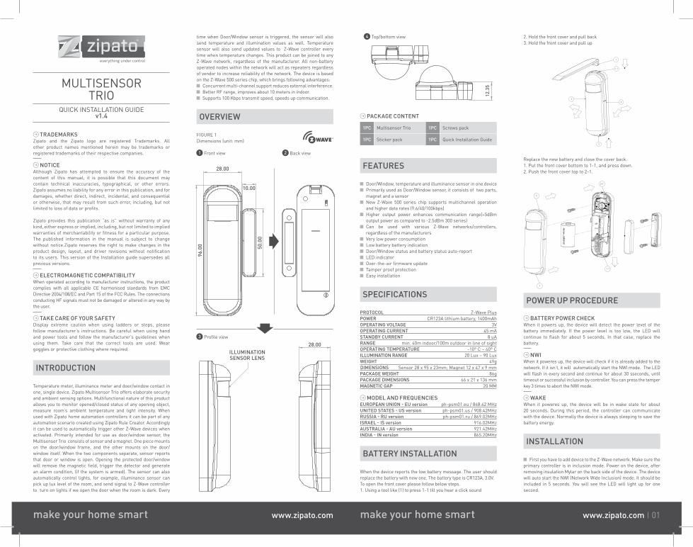
2. Hold the front cover and pull back3. Hold the front cover and pull up
1
2
2
3
1-1
Replace the new battery and close the cover back.1. Put the front cover bottom to 1-1, and press down.2. Push the front cover top to 2-1.
2
1
1-1
2-1
POWER UP PROCEDURE
BATTERY POWER CHECKWhen it powers up, the device will detect the power level of the battery immediately. If the power level is too low, the LED will continue to flash for about 5 seconds. In that case, replace the battery.
NWIWhen it poweres up, the device will check if it is already added to the network. If it isn’t, it will automatically start the NWI mode. The LED will flash in every second and continue for about 30 sseconds, until timeout or successful inclusion by controller. You can press the tamper key 3 times to abort the NWI mode.
WAKEWhen it poweres up, the device will be in wake state for about 20 seconds. During this period, the controller can communicate with the device. Normally the device is always sleeping to save the battery energy.
INSTALLATION
First you have to add device to the Z-Wave network. Make sure the primary controller is in inclusion mode. Power on the device, after removing insulation Mylar on the back side of the device. The device will auto start the NWI (Network Wide Inclusion) mode. It should be included in 5 seconds. You will see the LED will light up for one second.
PACKAGE CONTENT
1PC Multisensor Trio 1PC Screws pack
1PC Sticker pack 1PC Quick Installation Guide
FEATURES
Door/Window, temperature and illuminance sensor in one device Primarily used as Door/Window sensor, it consists of two parts, magnet and a sensor New Z-Wave 500 series chip supports multichannel operation and higher data rates (9.6/40/100kbps) Higher output power enhances communication range(+5dBm output power as compared to -2.5dBm 300 series) Can be used with various Z-Wave networks/controllers, regardless of the manufacturersVery low power consumptionLow battery battery indicationDoor/Window status and battery status auto-reportLED indicatorOver-the-air firmware updateTamper proof protectionEasy installation
SPECIFICATIONS
PROTOCOL Z-Wave PlusPOWER CR123A lithium battery, 1400mAhOPERATING VOLTAGE 3VOPERATING CURRENT 45 mASTANDBY CURRENT 8 uARANGE min. 40m indoor/100m outdoor in line of sightOPERATING TEMPERATURE -10° C ~ 40° CILLUMINATION RANGE 20 Lux ~ 90 LuxWEIGHT 49gDIMENSIONS Sensor 28 x 95 x 23mm; Magnet 12 x 47 x 9 mmPACKAGE WEIGHT 86g PACKAGE DIMENSIONS 66 x 21 x 136 mmMAGNETIC GAP 20 MM
MODEL AND FREQUENCIESEUROPEAN UNION - EU version ph-psm01.eu / 868.42 MHzUNITED STATES - US version ph-psm01.us / 908.42MHzRUSSIA - RU version ph-psm01.ru / 869.02MHzISRAEL - IS version 916.02MHzAUSTRALIA - AU version 921.42MHzINDIA - IN version 865.20MHz
BATTERY INSTALLATION
When the device reports the low battery message. The user should replace the battery with new one. The battery type is CR123A, 3.0V.To open the front cover please follow below steps.1. Using a tool like (1) to press 1-1 till you hear a click sound
12.3
5
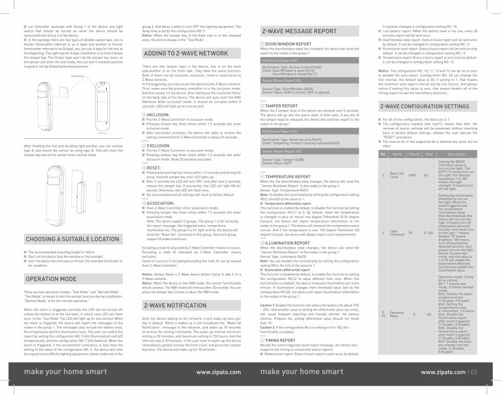
4 Top/bottom view
make your home smart www.zipato.com make your home smart www.zipato.com 01
time when Door/Window sensor is triggered, the sensor will also send temperature and illumination values as well. Temperature sensor will also send updated values to Z-Wave controller every time when temperature changes. This product can be joined to any Z-Wave network, regardless of the manufacturer. All non-battery operated nodes within the network will act as repeaters regardless of vendor to increase reliability of the network. The device is based on the Z-Wave 500 series chip, which brings following advantages:
Concurrent multi-channel support reduces external interference.Better RF range, improves about 10 meters in indoor.Supports 100 Kbps transmit speed, speeds up communication.
OVERVIEW
ILLUMINATIONSENSOR LENS
28.003 Profile view
FIGURE 1Dimensions (unit: mm)
50.0
0
10.00
28.00
96.0
0
1 Front view 2 Back view
Let Controller associate with Group 1 of the device, any light switch that should be turned on when the device should be associated with Group 2 of the device.
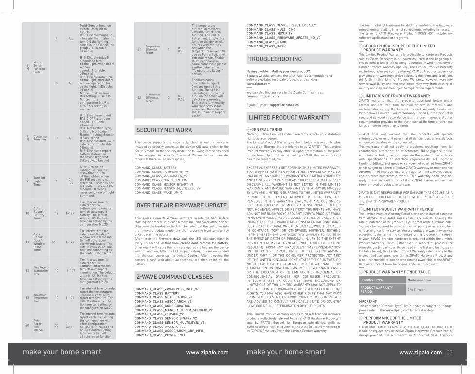
In the package there are two types of double coated tape, one is thicker (hereinafter referred to as A tape) and another is thinner (hereinafter referred to as B tape), you can use A tape for the test at the beginning. The right way for A tape installation is to stick it below the tamper key. The thicker tape won’t let the tamper key close, so the sensor will enter the test mode, You can test if installed position is good or not by following the below picture.
Back view
Testing Sponge
After finishing the test and deciding right position, you can remove tape A, and mount the sensor by using tape B. This will close the tamper key and let the sensor enter normal mode.
CHOOSING A SUITABLE LOCATION
The recommended mounting height is 160cm Don’t let the device face the window or the sunlight. Don’t let device face the source of heat. For example the heater or air-condition.
OPERATION MODE
There are two operation modes, “Test Mode” and “Normal Mode”. “Test Mode” is meant to test the sensor function during installation. “Normal Mode” is for the normal operation.“
When the event is triggered, normally the LED will be turned off, unless the battery is at the low level, in which case LED will flash once. In the “Test Mode” the LED will light up for one second. When the event is triggered, the device will report the messages to the nodes in the group 1. The messages also include the battery level, the temperature and the illumination level. The user can switch the report by setting the configuration NO. 5 bit4 (illumination) and bit5 (temperature), and the configuration NO. 7 bit6 (battery). When the event is triggered, if the environment luminance is less than the setting of the value of the configuration NO. 4, the device will emit the signal to turn ON the lighting equipment, whose nodes are in the
group 2. And delay a while to turn OFF the lighting equipment. The delay time is set by the configuration NO. 9.Notice: When the tamper key of the back side is in the released state, the device always in the “Test Mode”.
ADDING TO Z-WAVE NETWORK
There are two tamper keys in the device, one is on the back side,another is on the front side. They have the same function. Both of them can do inclusion, exclusion, reset or association to Z-Wave network.In the beggining, you have to join the device to the Z-Wave network. First, make sure the primary controller is in the inclusion mode. And then power on the device, after taking out the insulation Mylar on the back side of the device. The device will auto start the NWI (Network Wide Inclusion) mode. It should be included within 5 seconds. LED will light up for one second.
INCLUSION:Put the Z-Wave Controller in inclusion mode. Pressing tamper key three times within 1.5 seconds will enter inclusion mode. After successful inclusion, the device will wake to receive the setting command from Z-Wave Controller in about 20 seconds.
EXCLUSION:Put the Z-Wave Controller in exclusion mode. Pressing tamper key three times within 1.5 seconds will enter exclusion mode. Node ID has been excluded.
RESET: Pressing tamper key four times within 1.5 seconds and during 4th press, hold the tamper key until LED lights up. After 3 seconds the LED will turn OFF, and after next 2 seconds, release the tamper key. If successful, the LED will light ON for second. Otherwise, the LED will flash once. IDs are excluded and all settings will reset to factory default.
ASSOCIATION:Have Z-Wave Controller enter association mode. Pressing tamper key three times within 1.5 seconds will enter association mode.
Note: The device support 2 groups. The group 1 is for receiving the report message, like triggered event, temperature, illumination etc. The group 2 is for light control, the device will send the “Basic Set” command to this group. And each group support 8 nodes maximum.
Including a node ID allocated by Z-Wave Controller means inclusion. Excluding a node ID allocated by Z-Wave Controller means exclusion.Failed or success in including/excluding the node ID can be viewed from Z-Wave Controller.
Notice: Always Reset a Z-Wave device before trying to add it to a Z-Wave network.Notice: When the device is into NWI mode, the sensor functionality will be useless. The NWI mode will timeout after 30 seconds. You can press the tamper key 3 times to abort the NWI mode.
Z-WAVE NOTIFICATION
After the device adding to the network, it will wake-up once per day in default. When it wakes up it will broadcast the “Wake Up Notification” message to the network, and wake-up 10 seconds to receive the setting commands. The wake-up interval minimum setting is 30 minutes, and maximum setting is 120 hours. And the interval step is 30 minutes. If the user want to wake-up the device immediately, please remove the front cover, and press the tamper key once. The device will wake-up for 10 seconds.
Z-WAVE MESSAGE REPORT
DOOR/WINDOW REPORTWhen the door/window state has changed, the device will send the report to the nodes in the group 1.
Notification Report (V4)
Notification Type: Access Control (0x06)Event: Door/Window is open (0x16) Door/Window is closed (0x17)
Sensor Binary Report (V2)
Sensor Type: Door/Window (0x0A)Sensor Value: 0x00 is closed, 0xFF is opened.
TAMPER REPORTWhen the 2 tamper keys in the device are pressed over 5 seconds. The device will go into the alarm state. In that state, if any one of the tamper keys be released, the device will send the report to the nodes in the group 1.
Notification Report (V4)
Notification Type: Home Security (0x07)Event: Tampering. Product covering removed (0x03)
Sensor Binary Report (V2)
Sensor Type: Tamper (0x08)Sensor Value: 0xFF
TEMPERATURE REPORTWhen the the door/window state changes, the device will send the “Sensor Multilevel Report” to the nodes in the group 1.Sensor Type: Temperature (0x01)Note: To disable this functionality by setting the configuration setting N0.5, the bit5 of the value to 1.
Temperature differential reportThis function is enabled by default, to disable this function by setting the configuration NO.21 to 0. By default, when the temperature is changed to plus or minus one degree Fahrenheit (0.56 degree Celsius), the device will report temperature information to the nodes in the group 1. The device will measure the temperature every minute. And if the temperature is over 140 degree Fahrenheit (60 degree Celsius), the device will always report each measurement.
ILLUMINATION REPORTWhen the door/window state changes, the device will send the “Sensor Multilevel Report” to the nodes in the group 1.Sensor Type: Luminance (0x03)Note: You can disable this functionality by setting the configuration setting N0.5, the bit4 of the value to 1.
Illumination differential reportThis function is disabled by default, to enable this function by setting the configuration NO.22 to value different then zero. When this functionality is enabled, the device measures illumination per every minute. If illumination changes from threshold value (set by the configuration NO.22), the device will report illumination information to the nodes in the group 1.
Caution 1: Enable this function will reduce the battery life about 15%~ 20%. And another issue is setting the differential value too small, will cause frequent reporting and thereby shorten the battery lifetime. Propose the setting differential value should not small than 10.Caution 2: If the configuration No.4 is setting to 0 or 100, thisfunctionality is useless.
TIMING REPORTBeside the event triggered could report message, the device alsosupports the timing of unsolicited status reports.
Battery level report: Every 6 hours report is sent once, by default.
It could be changed in configuration setting NO. 10. Low battery report: When the battery level is too low, every 30 minutes report will be sent once. Door/window state report: Every 6 hours report will be sent once by default. It can be changed in configuration setting NO. 11. Illumination level report: Every 6 hours report will be sent once by default. It can be changed in configuration setting NO. 12. Temperature report: Every 6 hours report is sent once by default. It can be changed in configuration setting NO. 13.
Notice: The configuration NO. 10, 11, 12 and 13 can be set to zero to disable the auto report. Configuration NO. 20 can change the tick interval, the default value is 30, if setting to 1, that means the minimum auto report interval will be one minute. And please notice if setting this value to zero, that means disable all of the timing report except the low battery detection.
Z-WAVE CONFIGURATION SETTINGS
For all of the configuration, the data size is 1. The configuration marked with star(*), means that after the removal of device, settings will be preserved, without reverting back to factory default settings, unleass the user execute the “RESET” procedure. The reserve bit or not supported bit is allowed any value, but no effect
NO. Name Default Valid Description
2 Basic Set Level 0xFF All
Setting the BASIC command value toturn on the light. The 0xFF(-1) means turn on the light. For dimmerequipment 1 to 100 means the light strength. 0 means turn off the light.
4 LightThreshold 99 0~100
Setting the illumination threshold to turn on the light. When the event triggered and the environment illumination lower then the threshold, the device will turn on the light. 0 means turn off illumination detected function. And never turn on the light. 1 means darkest. 99 means brightest. 100 means turn off illumination detected function. And always turn on the light. Notice: In none test mode, only the value in 1 to 99 will enable the illumination detected function and update the illumination value.
5 (*)
OperationMode 0 All
Operation mode. Using bit to control. Bit1: 1 means test mode, 0 means normal mode. Bit2: Disable the door/window function. (1:Disable, 0:Enable) Bit3: Setting the temperature scale.0: Fahrenheit, 1:Celsius Bit4: Disable the illumination reportafter event triggered. (1:Disable, 0:Enable) Bit5: Disable the temperature reportafter event triggered. (1:Disable, 0:Enable) Bit7: Disable the back key release into test mode. (1:Disable,0:Enable)
make your home smart www.zipato.com make your home smart www.zipato.com 02
6 (*)
Multi-SensorFunctionSwitch
4 All
Multi-Sensor function switch. Using bit to control.Bit0: Disable magnetic integrate illumination to turn ON the lightingnodes in the association group 2. (1:Disable, 0:Enable)
0 All
Bit4: Disable delay 5 seconds to turnoff the light, when door/windowclosed. (1:Disable, 0:Enable) Bit5: Disable auto turn off the light, after door/window opened to turn on the light. (1:Disable, 0:Enable)Notice: If bit2 is zero, this setting is useless. Notice: If the configuration No.9 iszero, this setting is useless.
7 (*)
Costumer Function 0 All
Bit3: Disable send out BASIC OFF after door closed. (1:Disable,0:Enable) Bit4: Notification Type,0: Using Notification Report. 1: Using Sensor Binary Report. Bit5: Disable Multi CC in auto report. (1:Disable, 0:Enable) Bit6: Disable to report battery state when the device triggered. (1:Disable, 0:Enable)
9Turn OffLight Time
4 0 ~127
After turn on the lighting, setting thedelay time to turn off the lighting when the PIR motion is not detected. 8 seconds per tick, default tick is 4 (32seconds). 0 means never send turn off lightcommand.
10Auto ReportBattery Time
12 1~127
The interval time for auto report thebattery level. 0 means turn off auto report battery. The default value is 12. The tick time can setting by the configuration No.20.
11
Auto ReportDoor/WindowState Time
12 1~127
The interval time for auto report the door/window state. 0 means turn off auto reportdoor/window state. The default value is 12. The tick time can setting by the configuration No.20.
12Auto ReportIlluminationTime
12 1~127
The interval time for auto report theillumination. 0 means turn off auto reportillumination. The default value is 12. The tick time can setting by the configuration No.20.
13Auto ReportTemperature Time
12 1~127
The interval time for auto report the temperature. 0 means turn off auto report temperature. The default value is 12. The tick time can setting by the configuration No.20.
20Auto ReportTick Interval
30 0 ~0xFF
The interval time for auto report each tick. Setting this configuration willeffect configuration No.10, No.11, No.12 and No.13. Caution: Setting to 0 means turn offall auto report function.
21Temperature Differential Report
1 0 ~0x7F
The temperature differential to report.0 means turn off this function. The unit is Fahrenheit. Enable this function the device will detect every minutes.And when the temperature is over 140 degree Fahrenheit, it will continue report. Enable this functionality will cause some issue please see the detail in the “Temperature Report” section.
22IlluminationDifferentialReport
0 0 ~0x63
The illumination differential to report.0 means turn off this function. The unit is percentage. Enable this function the device willdetect every minutes.Enable this functionality will cause some issue please see the detail in the “Illumination Report” section.
SECURITY NETWORK
This device supports the security function. When the device is included by security controller, the device will auto switch to the security mode. In the security mode, the following commands need to be wrapped in Security Command Classes to communicate, otherwise there will be no response.
COMMAND_CLASS_BATTERYCOMMAND_CLASS_NOTIFICATION_V4COMMAND_CLASS_ASSOCIATION_V2COMMAND_CLASS_CONFIGURATIONCOMMAND_CLASS_SENSOR_BINARY_V2COMMAND_CLASS_SENSOR_MULTILEVEL_V5COMMAND_CLASS_WAKE_UP_V2
OVER THE AIR FIRMWARE UPDATE
This device supports Z-Wave firmware update via OTA. Before starting the procedure, please remove the front cover of the device. Otherwise the hardware check will be failed. Let the controller into the firmware update mode, and then press the front tamper key once to start the update. After finish the firmware download, the LED will start flash in every 0.5 second. At that time, please don’t remove the battery, otherwise it will cause the firmware upgrade to fail, and the device will not function. After the LED stops flashing, it is recommended that the user power up the device. Caution: After removing the battery, please wait about 30 seconds, and then re-install the battery.
Z-WAVE COMMAND CLASSES
COMMAND_CLASS_ZWAVEPLUS_INFO_V2COMMAND_CLASS_BATTERYCOMMAND_CLASS_NOTIFICATION_V4COMMAND_CLASS_ASSOCIATION_V2COMMAND_CLASS_CONFIGURATIONCOMMAND_CLASS_MANUFACTURER_SPECIFIC_V2COMMAND_CLASS_VERSION_V2COMMAND_CLASS_SENSOR_BINARY_V2COMMAND_CLASS_SENSOR_MULTILEVEL_V5COMMAND_CLASS_WAKE_UP_V2COMMAND_CLASS_ASSOCIATION_GRP_INFOCOMMAND_CLASS_POWERLEVEL
COMMAND_CLASS_DEVICE_RESET_LOCALLYCOMMAND_CLASS_MULTI_CMDCOMMAND_CLASS_SECURITYCOMMAND_CLASS_FIRMWARE_UPDATE_MD_V2COMMAND_CLASS_MARKCOMMAND_CLASS_BASIC
TROUBLESHOOTING
Having trouble installing your new product?Zipato’s website contains the latest user documentation and software updates for Zipato products and services:www.zipato.com
You can also find answers in the Zipato Community at: community.zipato.com
Zipato Support: [email protected]
LIMITED PRODUCT WARRANTY
GENERAL TERMSNothing in this Limited Product Warranty affects your statutory rights as a consumer.The Limited Product Warranty set forth below is given by Tri plus grupa d.o.o. (Europe) (herein referred to as “ZIPATO”). This Limited Product Warranty is only effective upon presentation of the proof of purchase. Upon further request by ZIPATO, this warranty card has to be presented, too.
EXCEPT AS EXPRESSLY SET FORTH IN THIS LIMITED WARRANTY, ZIPATO MAKES NO OTHER WARRANTIES, EXPRESS OR IMPLIED, INCLUDING ANY IMPLIED WARRANTIES OF MERCHANTABILITY AND FITNESS FOR A PARTICULAR PURPOSE. ZIPATO EXPRESSLY DISCLAIMS ALL WARRANTIES NOT STATED IN THIS LIMITED WARRANTY. ANY IMPLIED WARRANTIES THAT MAY BE IMPOSED BY LAW ARE LIMITED IN DURATION TO THE LIMITED WARRANTY PERIOD. TO THE EXTENT ALLOWED BY LOCAL LAW, THE REMEDIES IN THIS WARRANTY STATEMENT ARE CUSTOMER’S SOLE AND EXCLUSIVE REMEDIES AGAINST ZIPATO. THEY DO NOT, HOWEVER, AFFECT OR RESTRICT THE RIGHTS YOU HAVE AGAINST THE BUSINESS YOU BOUGHT A ZIPATO PRODUCT FROM. IN NO EVENT WILL ZIPATO BE LIABLE FOR LOSS OF DATA OR FOR INDIRECT, SPECIAL, INCIDENTAL, CONSEQUENTIAL (INCLUDING LOST PROFIT OR DATA), OR OTHER DAMAGE, WHETHER BASED IN CONTRACT, TORT, OR OTHERWISE. HOWEVER, NOTHING IN THIS AGREEMENT LIMITS ZIPATO’S LIABILITY TO YOU (I) IN THE EVENT OF DEATH OR PERSONAL INJURY TO THE EXTENT RESULTING FROM ZIPATO’S NEGLIGENCE, OR (II) TO THE EXTENT RESULTING FROM ANY FRAUDULENT MISREPRESENTATION ON THE PART OF ZIPATO, OR (III) TO THE EXTENT ARISING UNDER PART 1 OF THE CONSUMER PROTECTION ACT 1987 OF THE UNITED KINGDOM. SOME STATES OR COUNTRIES DO NOT ALLOW: (1) A DISCLAIMER OF IMPLIED WARRANTIES; (2) A LIMITATION ON HOW LONG AN IMPLIED WARRANTY LASTS OR THE EXCLUSION; OR (3) LIMITATION OF INCIDENTAL OR CONSEQUENTIAL DAMAGES FOR CONSUMER PRODUCTS. IN SUCH STATES OR COUNTRIES, SOME EXCLUSIONS OR LIMITATIONS OF THIS LIMITED WARRANTY MAY NOT APPLY TO YOU. THIS LIMITED WARRANTY GIVES YOU SPECIFIC LEGAL RIGHTS. YOU MAY ALSO HAVE OTHER RIGHTS THAT MAY VARY FROM STATE TO STATE OR FROM COUNTRY TO COUNTRY. YOU ARE ADVISED TO CONSULT APPLICABLE STATE OR COUNTRY LAWS FOR A FULL DETERMINATION OF YOUR RIGHTS.
This Limited Product Warranty applies to ZIPATO branded hardware products (collectively referred to as “ZIPATO Hardware Products”) sold by ZIPATO (Europe), its European subsidiaries, affiliates, authorized resellers, or country distributors (collectively referred to as “ZIPATO Resellers”) with this Limited Product Warranty.
The term “ZIPATO Hardware Product” is limited to the hardware components and all its internal components including firmware. The term “ZIPATO Hardware Product” DOES NOT include any software applications or programs.
GEOGRAPHICAL SCOPE OF THE LIMITED PRODUCT WARRANTY
This Limited Product Warranty is applicable to Hardware Products sold by Zipato Resellers in all countries listed at the beginning of this document under the heading “Countries in which this ZIPATO Limited Product Warranty applies”. The Limited Product Warranty will be honored in any country where ZIPATO or its authorized service providers offer warranty service subject to the terms and conditions set forth in this Limited Product Warranty. However, warranty service availability and response times may vary from country to country and may also be subject to registration requirements.
LIMITATION OF PRODUCT WARRANTYZIPATO warrants that the products described below under normal use are free from material defects in materials and workmanship during the Limited Product Warranty Period set forth below (“Limited Product Warranty Period”), if the product is used and serviced in accordance with the user manual and other documentation provided to the purchaser at the time of purchase (or as amended from time to time).
ZIPATO does not warrant that the products will operate uninterrupted or error-free or that all deficiencies, errors, defects or non-conformities will be corrected.This warranty shall not apply to problems resulting from: (a) unauthorized alterations or attachments; (b) negligence, abuse or misuse, including failure to operate the product in accordance with specifications or interface requirements; (c) improper handling; (d) failure of goods or services not obtained from ZIPATO or not subject to a then-effective ZIPATO warranty or maintenance agreement; (e) improper use or storage; or (f) fire, water, acts of God or other catastrophic events. This warranty shall also not apply to any particular product if any ZIPATO serial number has been removed or defaced in any way.
ZIPATO IS NOT RESPONSIBLE FOR DAMAGE THAT OCCURS AS A RESULT OF YOUR FAILURE TO FOLLOW THE INSTRUCTIONS FOR THE ZIPATO HARDWARE PRODUCT.
LIMITED PRODUCT WARRANTY PERIODThe Limited Product Warranty Period starts on the date of purchase from ZIPATO. Your dated sales or delivery receipt, showing the date of purchase of the product, is your proof of the purchase date. You may be required to provide proof of purchase as a condition of receiving warranty service. You are entitled to warranty service according to the terms and conditions of this document if a repair to your ZIPATO branded hardware is required within the Limited Product Warranty Period. [Other than in respect of products for domestic use (in particular those listed in the first and last boxes in the table below), this Limited Product Warranty extends only to the original end user purchaser of this ZIPATO Hardware Product and is not transferable to anyone who obtains ownership of the ZIPATO Hardware Product from the original end-user purchaser.
PRODUCT WARRANTY PERIOD TABLE
PRODUCT TYPE Multisensor Trio
PRODUCT WARRANTY PERIOD One (1) year
IMPORTANTThe content of “Product Type” listed above is subject to change; please refer to the www.zipato.com for latest update.
PERFORMANCE OF THE LIMITED PRODUCT WARRANTY
If a product defect occurs, ZIPATO’s sole obligation shall be to repair or replace any defective Zipato Hardware Product free of charge provided it is returned to an Authorized ZIPATO Service
make your home smart www.zipato.com make your home smart www.zipato.com 03
Centre during the Limited Warranty Period. Such repair or replacement will be rendered by ZIPATO at an Authorized ZIPATO Service Centre. All component parts or hardware products that are replaced under this Limited Product Warranty become the property of ZIPATO. The replacement part or product takes on the remaining Limited Warranty Period of the replaced part or product. The replacement product need not be new or of an identical make, model or part; ZIPATO may in its discretion replace the defective product (or any part thereof) with any reconditioned equivalent (or superior) product in all material respects to the defective product.
WARRANTORTri plus grupa d.o.o.Banjavciceva 1110 000 ZagrebCROATIA
TEL +385 (0)1 4004 404FAX +385 (0)1 4004 405
DECLARATION OF CONFORMITY
The manufacturer Tri plus grupa d.o.o declares under our sole responsibility that the product:
Marketing model: Multisensor TrioRegulatory model: ph-psm01Trade/Brand name: Zipato
is in conformity with the Low Voltage Directive 2006/95/EC, EMC Directive 2004/108/EC, R&TTE Directive 1995/5/EC and carries the CE marking accordingly.The following harmonized standards were applied:
R&TTE (1995/5/EC)EN 300 220-1: V2.4.1EN 300 220-2: V2.4.1
EMC (2004/108/EC)EN 301 489-1: V1.9.2EN 301 489-3: V1.6.1
LVD (2006/95/EC)EN 60950-1:2006 + A11:2009 + A1:2010 + A12:2011
Changes or modifications not expressly approved by Tri plus grupa d.o.o. for compliance could void the user’s authority to operate the equipment.
THIS DEVICE COMPLIES WITH PART 15 OF THE FCC RULES.Operation is subject to the following two conditions:1 | this device may not cause harmful interference, and 2 | this device must accept any interference received, including interference that may cause undesired operation.
NOTE: Changes or modifications not expressly approved by Zipato for compliance could void the user’s authority to operate the equipment. This equipment has been tested and found to comply with the limits for a Class B digital device, pursuant to Part 15 of the FCC Rules. These limits are designed to provide reasonable protection against harmful interference in a residential installation. This equipment generates, uses and can radiate radio frequency energy and, if not installed and used in accordance with the instructions, may cause harmful interference to radio communications. However, there is no guarantee that interference will not occur in a particular installation. If this equipment does cause harmful interference to radio or television reception, which can be
determined by turning the equipment off and on, the user is encouraged to try to correct the interference by one or more of the following measures:
Reorient or relocate the receiving antenna.Increase the separation between the equipment and receiver. Connect the equipment into an outlet on a circuit different from that to which the receiver is connected. Consult the dealer or an experienced radio/TV technician for help.
DISPOSING AND RECYCLING YOUR PRODUCT When it reaches end of life, dispose of the product according to your local enviromental laws, guidelines and regulations.
BATTERY DISPOSALDispose of batteries according to your local enviromental laws, guidelines and regulations.
This symbol on the product or packaging means that accordingto local laws and regulations needs to be disposed of separatelyfrom household waste. Once this product has reached the end of its life, please take it to a collection point (recycle facilites) designated by your local authorities, some will accept your product for free or simply drop it off at your Zipato re-seller store. By recycling the product and its packaging in this manner you help to conserve the environment and protect human health. At Zipato, we understand and are committed to reducing any impact our operations and products may have on the environment. To minimize this impact Zipato designs and builds its products to be as environmentally friendly as possible, by using recyclable, low toxic materials in both products and packaging
COPYRIGHT © 2015 Tri plus grupa d.o.o. All Rights Reserved.No part of this manual may be reproduced or transmitted in any form without the expressed, written permission of Tri plus grupa d.o.o.
make your home smart www.zipato.com make your home smart www.zipato.com 04