Embed Size (px)
Citation preview
Multiplexing
Lecture 4
Paul Flynn

Multiplexing

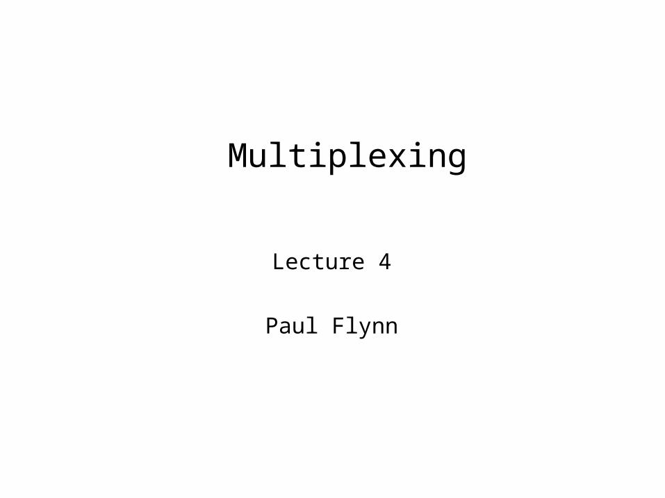
Frequency Division MultiplexingFDMUseful bandwidth of medium exceeds
required bandwidth of channelEach signal is modulated to a different
carrier frequencyCarrier frequencies separated so signals
do not overlap (guard bands)e.g. broadcast radioChannel allocated even if no data
Frequency Division MultiplexingDiagram
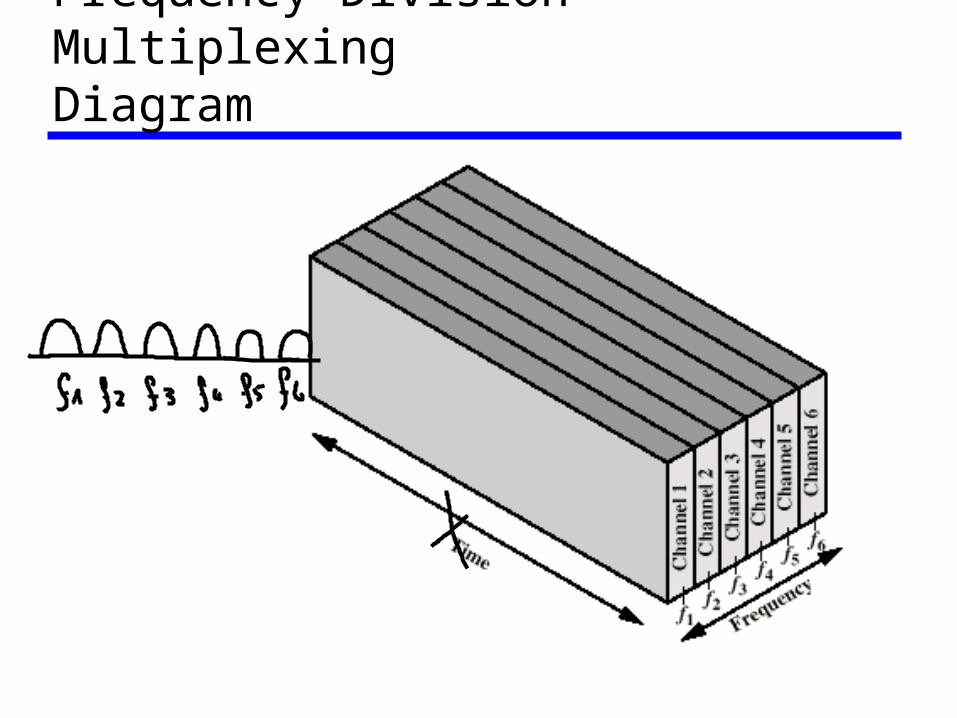
FDM System
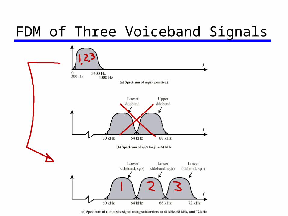
FDM of Three Voiceband Signals
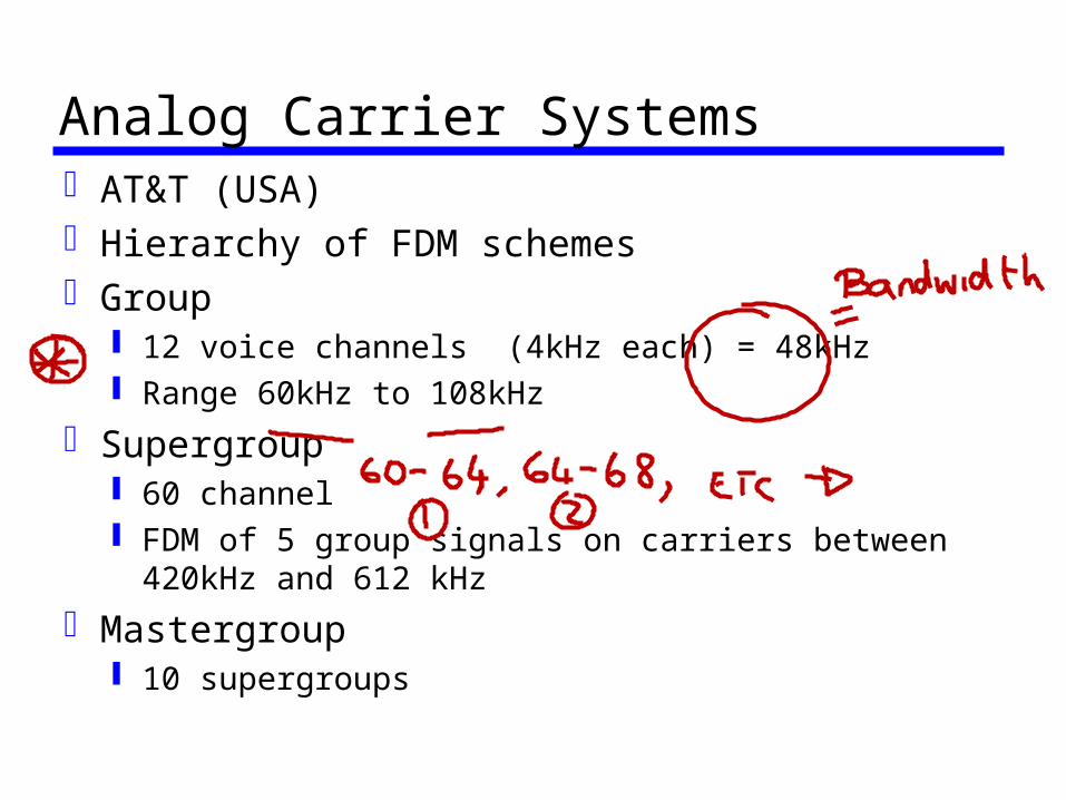
Analog Carrier SystemsAT&T (USA)Hierarchy of FDM schemesGroup
12 voice channels (4kHz each) = 48kHz Range 60kHz to 108kHz
Supergroup 60 channel FDM of 5 group signals on carriers between
420kHz and 612 kHz
Mastergroup 10 supergroups
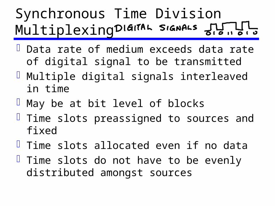
Synchronous Time Division MultiplexingData rate of medium exceeds data rate of
digital signal to be transmittedMultiple digital signals interleaved in timeMay be at bit level of blocksTime slots preassigned to sources and
fixedTime slots allocated even if no dataTime slots do not have to be evenly
distributed amongst sources

Time Division Multiplexing
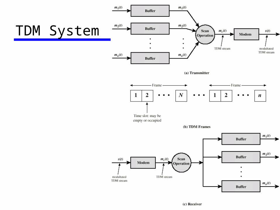
TDM System
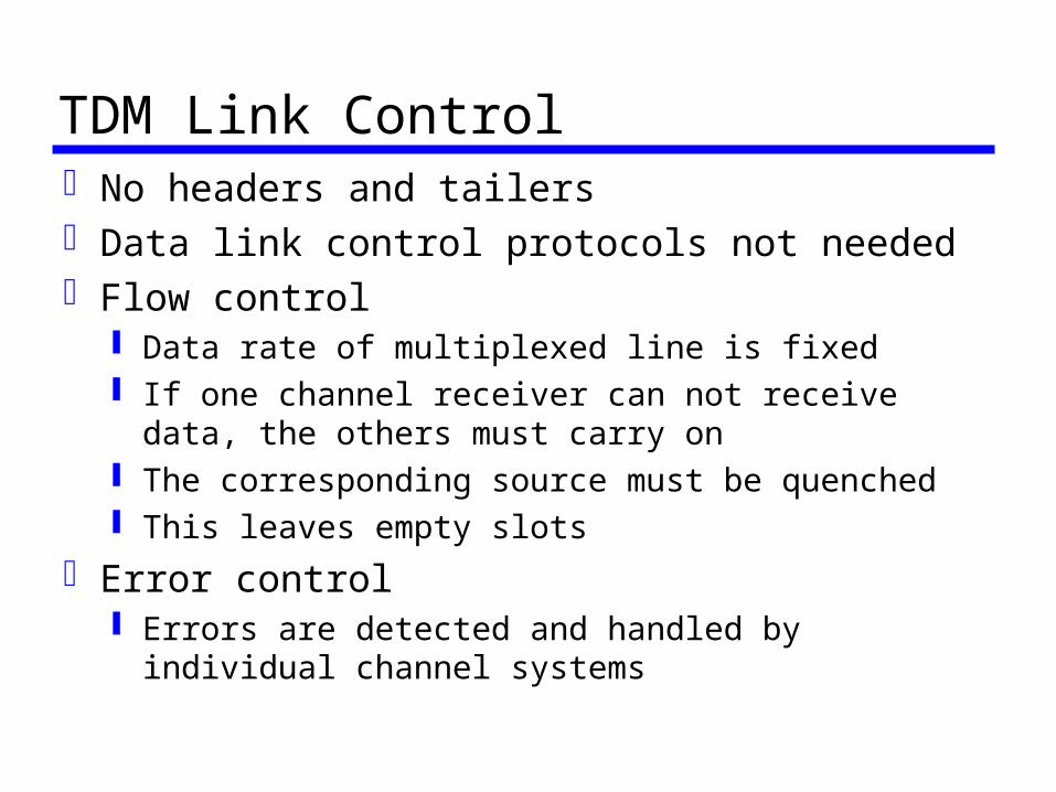
TDM Link ControlNo headers and tailersData link control protocols not neededFlow control
Data rate of multiplexed line is fixed If one channel receiver can not receive data, the
others must carry on The corresponding source must be quenched This leaves empty slots
Error control Errors are detected and handled by individual
channel systems

Data Link Control on TDM
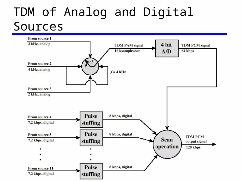
TDM of Analog and Digital Sources
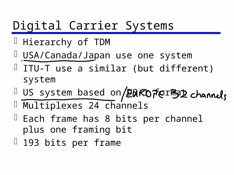
Digital Carrier SystemsHierarchy of TDMUSA/Canada/Japan use one systemITU-T use a similar (but different) systemUS system based on DS-1 formatMultiplexes 24 channelsEach frame has 8 bits per channel plus
one framing bit193 bits per frame
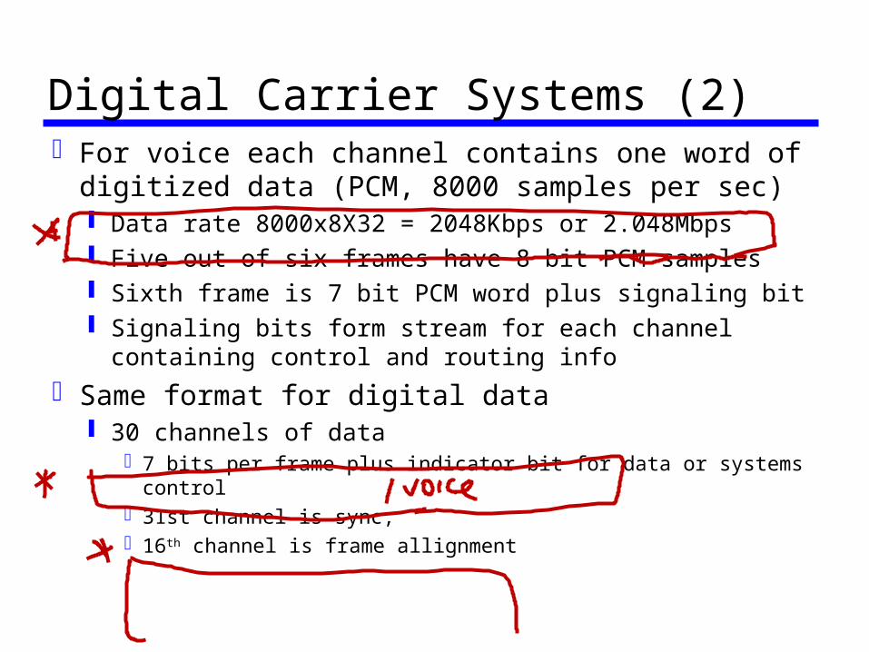
Digital Carrier Systems (2)For voice each channel contains one word of
digitized data (PCM, 8000 samples per sec) Data rate 8000x8X32 = 2048Kbps or 2.048Mbps Five out of six frames have 8 bit PCM samples Sixth frame is 7 bit PCM word plus signaling bit Signaling bits form stream for each channel
containing control and routing info
Same format for digital data 30 channels of data
7 bits per frame plus indicator bit for data or systems control31st channel is sync,16th channel is frame allignment
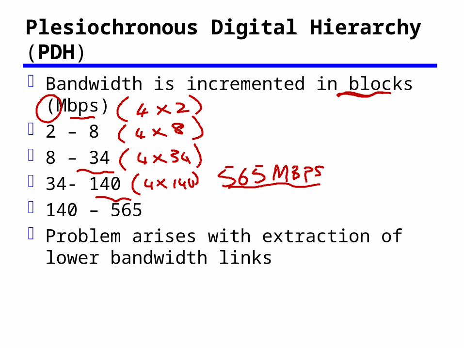
Plesiochronous Digital Hierarchy (PDH) Bandwidth is incremented in blocks
(Mbps)2 – 88 – 3434- 140140 – 565Problem arises with extraction of lower
bandwidth links
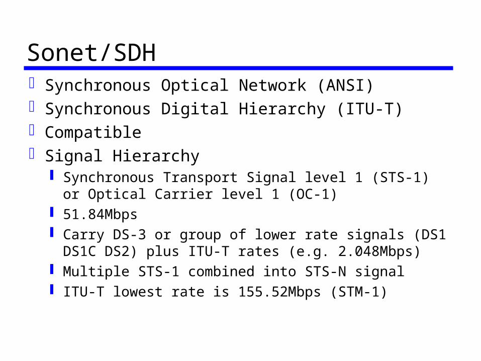
Sonet/SDHSynchronous Optical Network (ANSI)Synchronous Digital Hierarchy (ITU-T)CompatibleSignal Hierarchy
Synchronous Transport Signal level 1 (STS-1) or Optical Carrier level 1 (OC-1)
51.84Mbps Carry DS-3 or group of lower rate signals (DS1
DS1C DS2) plus ITU-T rates (e.g. 2.048Mbps) Multiple STS-1 combined into STS-N signal ITU-T lowest rate is 155.52Mbps (STM-1)
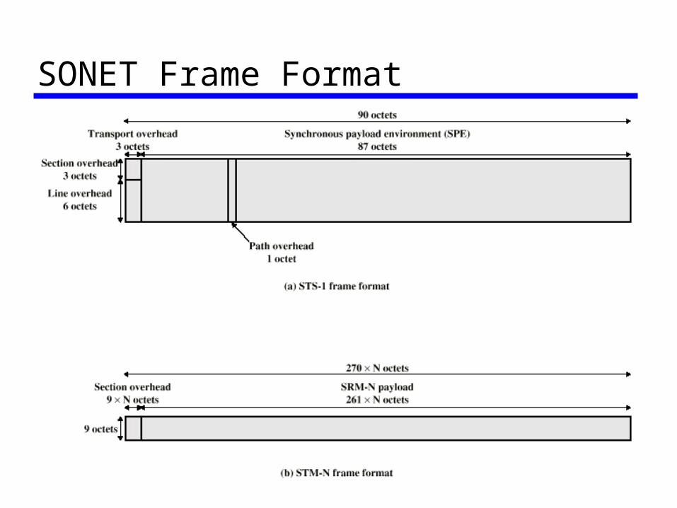
SONET Frame Format
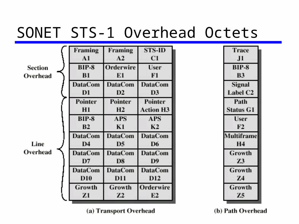
SONET STS-1 Overhead Octets
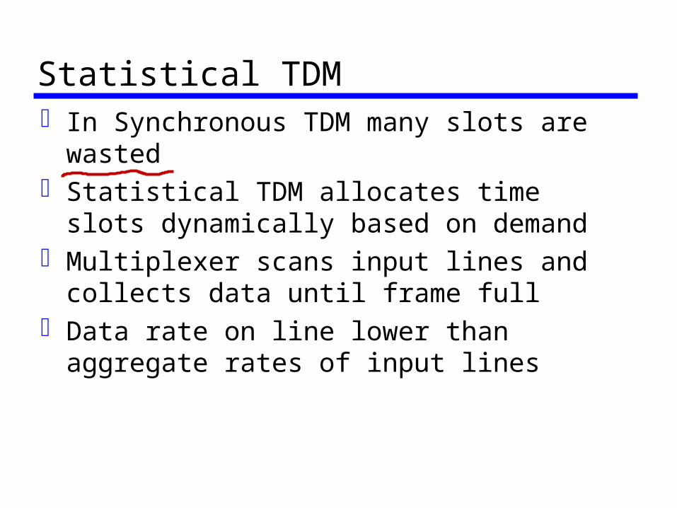
Statistical TDMIn Synchronous TDM many slots are
wastedStatistical TDM allocates time slots
dynamically based on demandMultiplexer scans input lines and collects
data until frame fullData rate on line lower than aggregate
rates of input lines
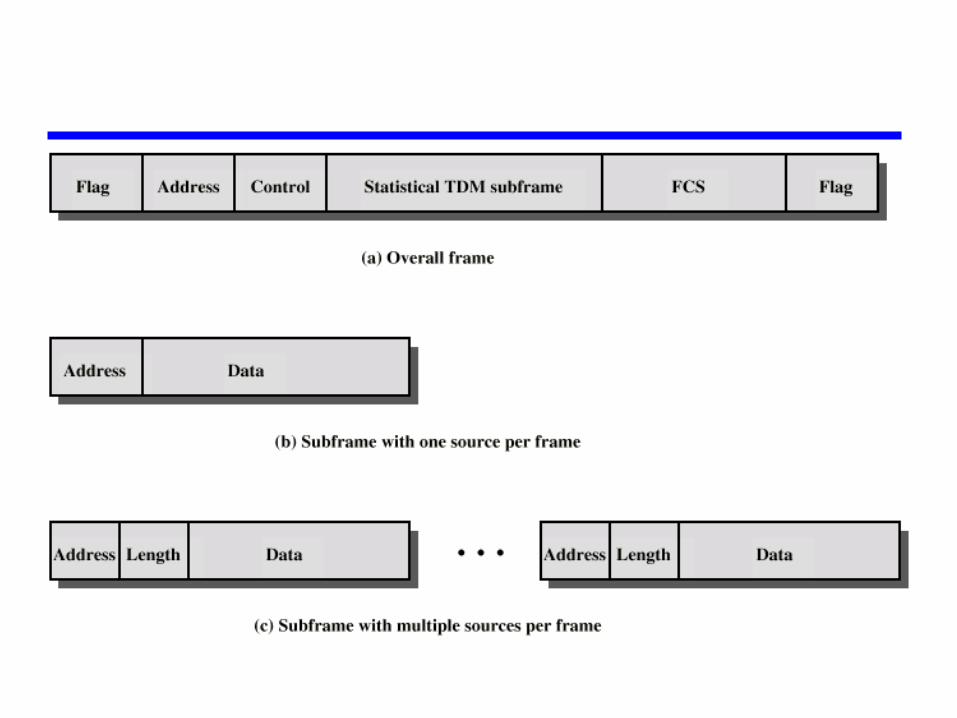
Statistical TDM Frame Formats
PerformanceOutput data rate less than aggregate
input ratesMay cause problems during peak periods
Buffer inputs Keep buffer size to minimum to reduce delay