Embed Size (px)
Citation preview

Multiphase Modeling of Water Injection on Flame Deflector
Cp, Cp,, di
0 epi
!Ni Fs, FD, FL, Fpc, FrD, FvM, Lvi rhi Ni pi Pr
Bruce T. Vu* NASA K ennedy Space Center, FL 32899
Nili Bachchant Oshin Peroomiant Vedat Akdag§ Metacomp Technologies, Inc. , CA 91301
This paper describes the use of an Eulerian Dispersed Phase (EDP) model to simulate the water injected from the flame deflector and its interaction with supersonic rocket exhaust from a proposed Space Launch System (SLS) vehicle. The Eulerian formulation, as part of the multi-phase framework, is described. The simulations show that water cooling is only effective over the region under the liquid engines. Likewise, the water injection provides only minor effects over the surface area under the solid engines.
Nomenclature
constant pressure specific heat of fluid , J / kg-K constant pressure specific heat of particle species i, J / kg-K average particle diameter of particle species i, m total internal energy (thermal and kinetic energy) of particle species i, J /kg Nusselt equation correction factor of particle species i buoyancy force on particle species i, N interphase drag force on particle species i, N lift force on particle species i, N pressure gradient force on particle species i, N turbulent dispersion force on particle species i, N virtual mass force on particle species i, N Latent heat of evaporation of species i, J /kg rate of production of mass for particle species i, kg/ m3-s number density of particle species i, m-3
pressure of particle species i, Pa Prandtl number
Psat saturation pressure , Pa P sat,ref reference saturation pressure, Pa
ambient temperature, K fluid temperature, K temperature of particle species i, K evaporation temperature of particle species i, K vector velocity of particle species i, m/s heat flux per particle species i, W jm3
gas constant of the evaporation of particle species i, m2 js2-K
*Lead, Fluid Systems Group, Senior AIAA Member. tsenior Scientist, Senior AIAA Member. ~Chief Technology Officer, Senior AIAA Member. §Senior Engineer.
1 of 13
American Institute of Aeronautics and Astronautics
https://ntrs.nasa.gov/search.jsp?R=20130014503 2018-07-08T10:04:33+00:00Z
ri average particle radius of species i, m Ctv correction factor in the Hertz-Knudsen equation >.1 heat conductivity of fluid ,W /m-K f..LJ dynamic viscosity of fluid , Pa-s C:pi emissivity coefficient of particle species i (J Boltzmann constant of radiation, 5.67 X w-8
' w /m2-K4
Pvi "fluidized" density of particle species i, kg/m3
Pvi material density of particle species i, kg/m3
TTi temperature relaxation time of particle species i, s Tui Stokes relaxation time of particle species i, s
I. Introduct ion
Since the retirement of the Space Shuttle, NASA has been developing a new heavy-lift capability, the Space Launch System (SLS). In conjunction with this development, NASA is re-assessing their launch site capabilities. One key component of particular interest is the Main Flame Deflector (MFD). The main purpose of the MFD is to minimize the plume impingement effects on the launch facility and to minimize the induced environmental effects on the vehicle. The MFD must be protected from harsh thermal environments generated by the plume impingement.
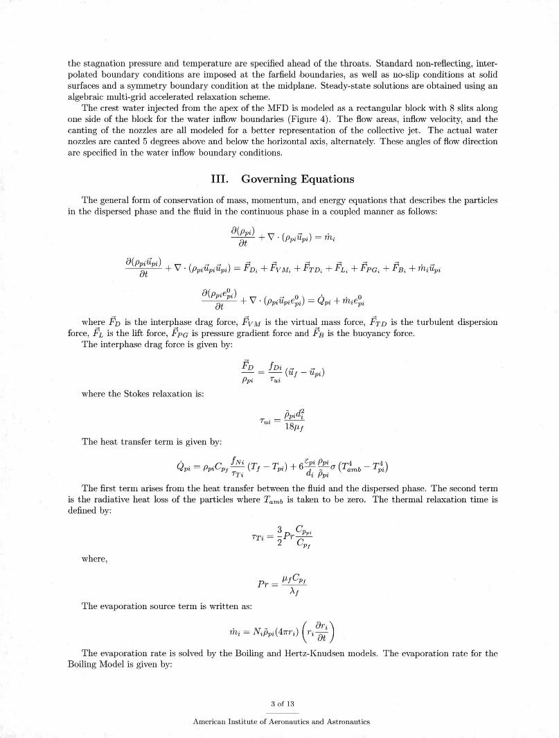
Currently, the MFD is kept cool by water sprays from the nozzles mounted on the apex of the deflector (Figures 1). The MFD water is one of the many water suppression systems employed at the launch complex. There are also water nozzles mounted around the exhaust hole to reduce the ignition overpressures and water rainbirds mounted on the launch deck to suppress the launch acoustics. This study focuses only on the MFD water nozzles, which can deliver water flow rates up to 300,000 gallons per minute (gpm) on both sides of the deflectors (Figure 2).
Recent advances in computational fluid dynamics (CFD) technique and computing resources have provided the necessary predictive capabilities during the MFD redesign. 1•2 However, these predictions often neglect multi-phase modeling to avoid model complexity and to reserve conservatism associated with uncooled or dry rocket plumes. Since the conservative results show severe thermal environments, it is prudent to know the effect of the water suppression system on the MFD in order to ensure that the MFD is not overdesigned.
The interaction of water sprays with supersonic flow is a complex phenomenon as it involves condensation, evaporation, diffusion, and dispersion processes. In this paper, the Eulerian Dispersed Phase (EDP) model is employed to model the water sprays into the gaseous environment. The EDP is coupled with the multispecies gaseous flow via source terms that govern the mass, momentum and thermal transfers between the two phases. The solutions allow designers to evaluate the effectiveness of water suppression systems on the MFD.
II. Modeling
The analysis pertains to a complex system involving multi-phase, multi-species, and complex geometry. These complexities provide a significant computational challenge. All modeling reported in this paper was performed using CFD++ 12.1 , a multi-purpose CFD software suite developed by Metacomp Technologies, lnc.3- 5
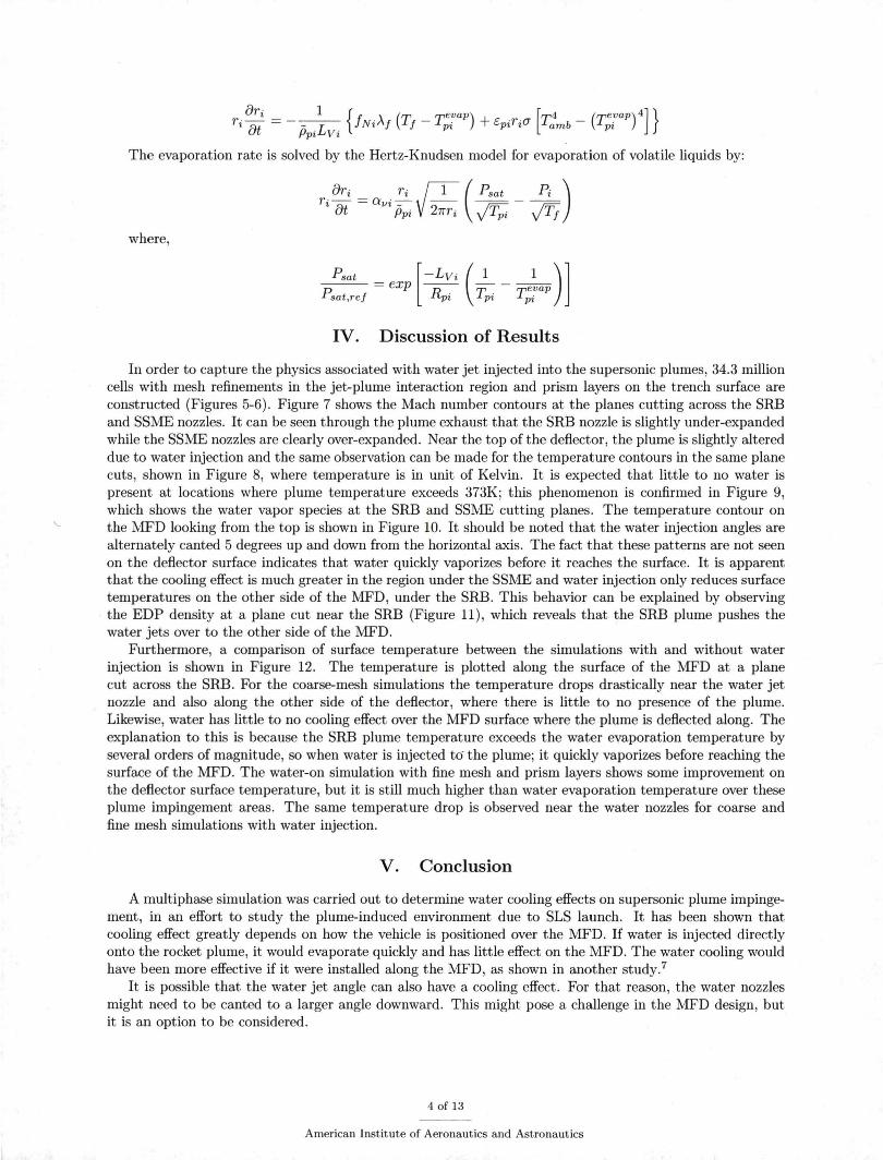
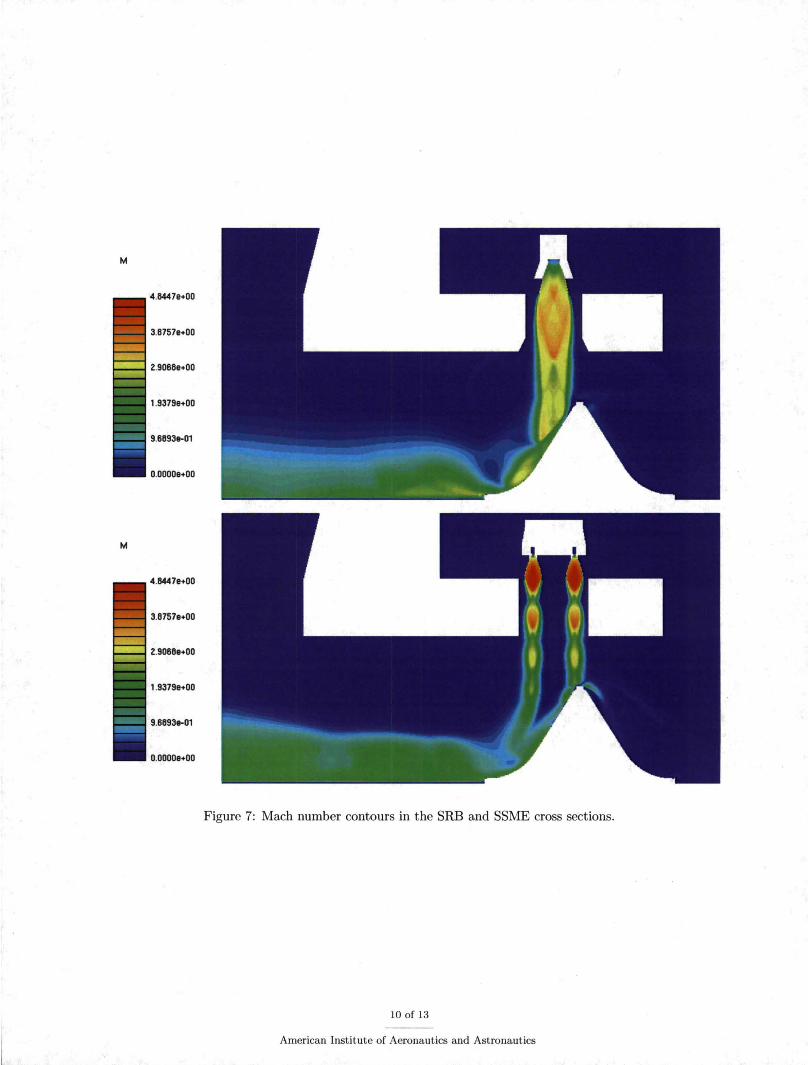
A multi-block, unstructured mesh is created to model the two solid and four liquid engine configurations on the launch pad (Figure 3). The mesh comprises of 34.3 million cells. A symmetry boundary condition is used to reduce the computational domain by half. The entire domain is initialized with a quiescent flow field.
The solution is based on compressible, multi-species, Reynolds-Averaged Navier-Stokes (RANS) with a realizable k-c: turbulence model. The multi-species simulation utilizes four species groups: SSME, SRB, water vapor, and air. The properties required to describe these groups include gas constants, molecular weights and specific heats. For the SSME and SRB groups, those properties were obtained from running a chemical equilibrium with applications (CEA).6 The simulation starts from the combustion chamber where
2 of 13
American Institute of Aeronautics and Astronautics
the stagnation pressure and temperature are specified ahead of the throats. Standard non-reflecting, interpolated boundary conditions are imposed at the farfield boundaries, as well as no-slip conditions at solid surfaces and a symmetry boundary condition at the midplane. Steady-state solutions are obtained using an algebraic multi-grid accelerated relaxation scheme.
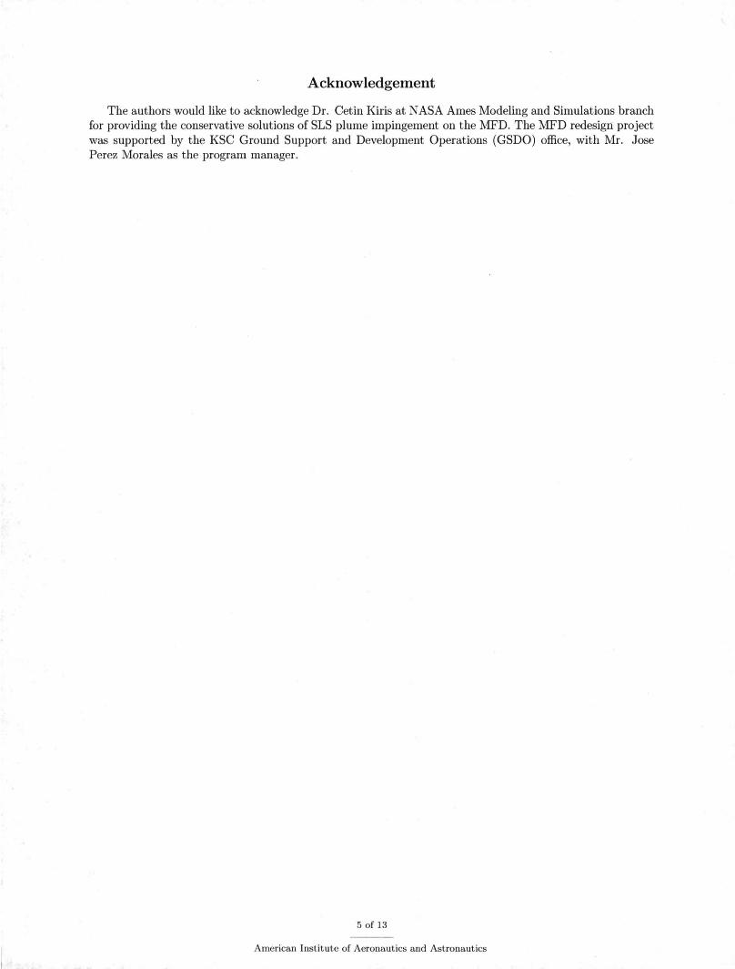
The crest water injected from the apex of the MFD is modeled as a rectangular block with 8 slits along one side of the block for the water inflow boundaries (Figure 4). The flow areas, inflow velocity, and the canting of the nozzles are all modeled for a better representation of the collective jet. The actual water nozzles are canted 5 degrees above and below the horizontal axis, alternately. These angles of flow direction are specified in the water inflow boundary conditions.
III. Governing Equations
The general form of conservation of mass, momentum, and energy equations that describes the particles in the dispersed phase and the fluid in the continuous phase in a coupled manner as follows:
a(ppiegi ) ~ 0 . . 0 at + \7 · (Ppi Upiepi) = Qpi + miepi
where Fv is the interphase drag force, Fv M is the virtual mass force, Frv is the turbulent dispersion force, FL is the lift force, Fpc is pressure gradient force and FE is the buoyancy force .
The interphase drag force is given by:
Fv !Di (~ ~ ) -=- Uj-Upi Ppi Tui
where the Stokes relaxation is:
The heat transfer term is given by:
Q. C fNi (T ,., ) 6 c:pi Ppi (T4 T4) pi= Ppi Pt- f- 1 pi + -d -_-(1 amb- pi
TTi i Ppi
The first term arises from the heat transfer between the fluid and the dispersed phase. The second term is the radiative heat loss of the particles where Tamb is taken to be zero. The thermal relaxation time is defined by:
where,
The evaporation source term is written as:
mi = Nd5pi(47rri) (ri ~i) The evaporation rate is solved by the Boiling and Hertz-Knudsen models. The evaporation rate for the
Boiling Model is given by:
3 of 13
American Institute of Aeronautics and Astronautics
Ori _ 1 {f ( evap) [ 4 ( evap)4]} ri!:)- -~L . Ni>..f Tf- Tpi + CpiTi(j Tamb- Tpi ut Ppt Vt
The evaporation rate is solved by the Hertz-Knudsen model for evaporation of volatile liquids by:
where,
PPsat = exp [-:vi (; . _ T e:ap)] sat,ref pt pt pt
IV. Discussion of Results
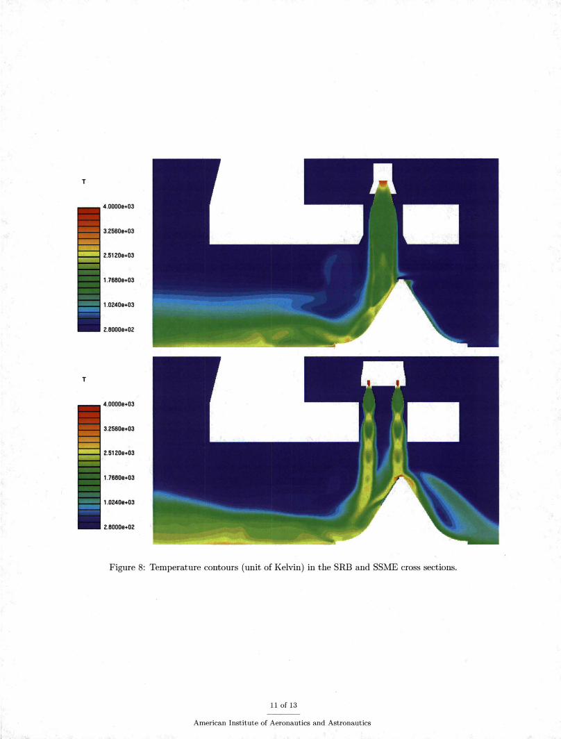
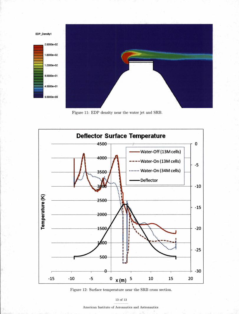
In order to capture the physics associated with water jet injected into the supersonic plumes, 34.3 million cells with mesh refinements in the jet-plume interaction region and prism layers on the trench surface are constructed (Figures 5-6) . Figure 7 shows the Mach number contours at the planes cutting across the SRB and SSME nozzles. It can be seen through the plume exhaust that the SRB nozzle is slightly under-expanded while the SSME nozzles are clearly over-expanded. Near the top of the deflector , the plume is slightly altered due to water injection and the same observation can be made for the temperature contours in the same plane cuts, shown in Figure 8, where temperature is in unit of Kelvin. It is expected that little to no water is present at locations where plume temperature exceeds 373K; this phenomenon is confirmed in Figure 9, which shows the water vapor species at the SRB and SSME cutting planes. The temperature contour on the MFD looking from the top is shown in Figure 10. It should be noted that the water injection angles are alternately canted 5 degrees up and down from the horizontal axis. The fact that these patterns are not seen on the deflector surface indicates that water quickly vaporizes before it reaches the surface. It is apparent that the cooling effect is much greater in the region under the SSME and water injection only reduces surface temperatures on the other side of the MFD, under the SRB. This behavior can be explained by observing the EDP density at a plane cut near the SRB (Figure 11), which reveals that the SRB plume pushes the water jets over to the other side of the MFD.
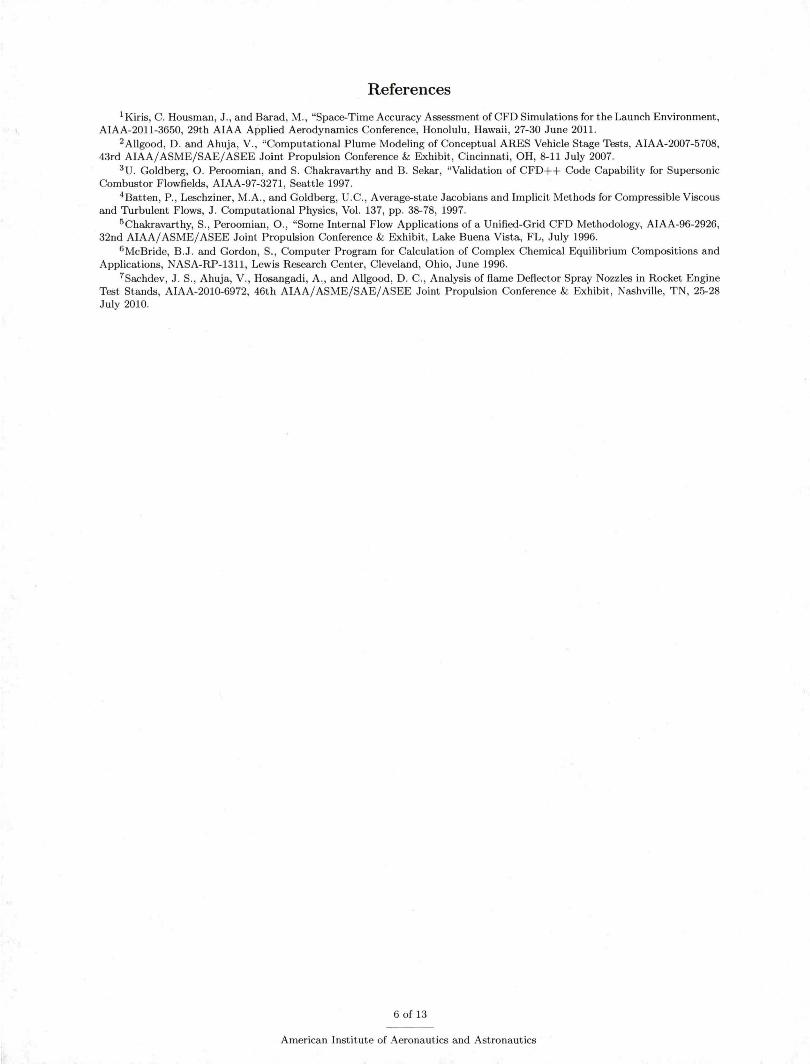
Furthermore, a comparison of surface temperature between the simulations with and without water injection is shown in Figure 12. The temperature is plotted along the surface of the MFD at a plane cut across the SRB. For the coarse-mesh simulations the temperature drops drastically near the water jet nozzle and also along the other side of the deflector, where there is little to no presence of the plume. Likewise, water has little to no cooling effect over the MFD surface where the plume is deflected along. The explanation to this is because the SRB plume temperature exceeds the water evaporation temperature by several orders of magnitude, so when water is injected to' the plume; it quickly vaporizes before reaching the surface of the MFD. The water-on simulation with fine mesh and prism layers shows some improvement on the deflector surface temperature, but it is still much higher than water evaporation temperature over these plume impingement areas. The same temperature drop is observed near the water nozzles for coarse and fine mesh simulations with water injection.
V. Conclusion
A multiphase simulation was carried out to determine water cooling effects on supersonic plume impingement, in an effort to study the plume-induced environment due to SLS launch. It has been shown that cooling effect greatly depends on how the vehicle is positioned over the MFD. If water is injected directly onto the rocket plume, it would evaporate quickly and has little effect on the MFD. The water cooling would have been more effective if it were installed along the MFD, as shown in another study.7
It is possible that the water jet angle can also have a cooling effect. For that reason, the water nozzles might need to be canted to a larger angle downward. This might pose a challenge in the MFD design, but it is an option to be considered.
4 of 13
American Institute of Aeronautics and Astronautics
Acknowledgement
The authors would like to acknowledge Dr. Cetin Kiris at NASA Ames Modeling and Simulations branch for providing the conservative solutions of SLS plume impingement on the MFD. The MFD redesign project was supported by the KSC Ground Support and Development Operations (GSDO) office, with Mr. Jose Perez Morales as the program manager.
5 of 13
American Institute of Aeronautics and Astronautics
References 1 Kiris, C. Housman, J. , and Bar ad, M., "Space-Time Accuracy Assessment of CFD Simulations for the Launch Environment,
AIAA-2011-3650, 29th AIAA Applied Aerodynamics Conference, Honolulu, Hawaii , 27-30 June 2011 . 2 Allgood, D. and Ahuja, V., "Computational P lume Modeling of Conceptual ARES Vehicle Stage Tests, AIAA-2007-5708,
43rd AIAA/ ASME/SAE/ ASEE Joint Propulsion Conference & Exhibit , Cincinnati, OH, 8-11 July 2007. 3 U. Goldberg, 0. Peroomian, a nd S. Chakravarthy and B. Sekar, "Validation of CFD++ Code Capability for Supersonic
Combustor Flowfields, AIAA-97-3271, Seattle 1997. 4 Batten , P. , Leschziner, M.A., and Goldberg, U.C., Average-state Jacobians and Implicit Methods for Compressible Viscous
and Turbulent Flows, J. Computational Physics, Vol. 137, pp. 38-78, 1997. 5 Chakravarthy, S. , Peroomian, 0., "Some Internal Flow Applications of a Unified-Grid CFD Methodology, AIAA-96-2926,
32nd AIAA/ASME/ASEE Joint Propulsion Conference & Exhibit, Lake Buena Vista, FL, July 1996. 6 McBride, B.J. and Gordon, S., Computer Program for Calculation of Complex Chemical Equilibrium Compositions and
Applications, NASA-RP-1311, Lewis Research Center , Cleveland, Ohio, June 1996. 7Sachdev, J. S., Ahuja, V., Hosangadi, A., and Allgood, D. C., Analysis of flame Deflector Spray Nozzles in Rocket Engine
Test Stands, AIAA-2010-6972, 46th AIAA/ ASME/SAE/ ASEE Joint Propulsion Conference & Exhibit, Nashville, TN, 25-28 July 2010.
6 of 13
American Institute of Aeronautics and Astronautics
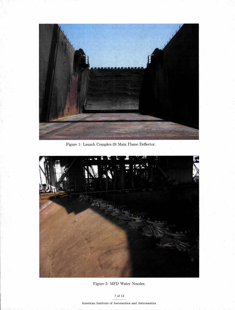
Figure 1: Launch Complex-39 Main Flame Deflector.
Figure 2: MFD Water Nozzles.
7 of 13
American Institute of Aeronautics and Astronautics

Figure 3: Truncated SLS vehicle above the Main Flame Deflector.
Figure 4: MFD Apex.
8 of 13
American Institute of Aeronautics and Astronautics
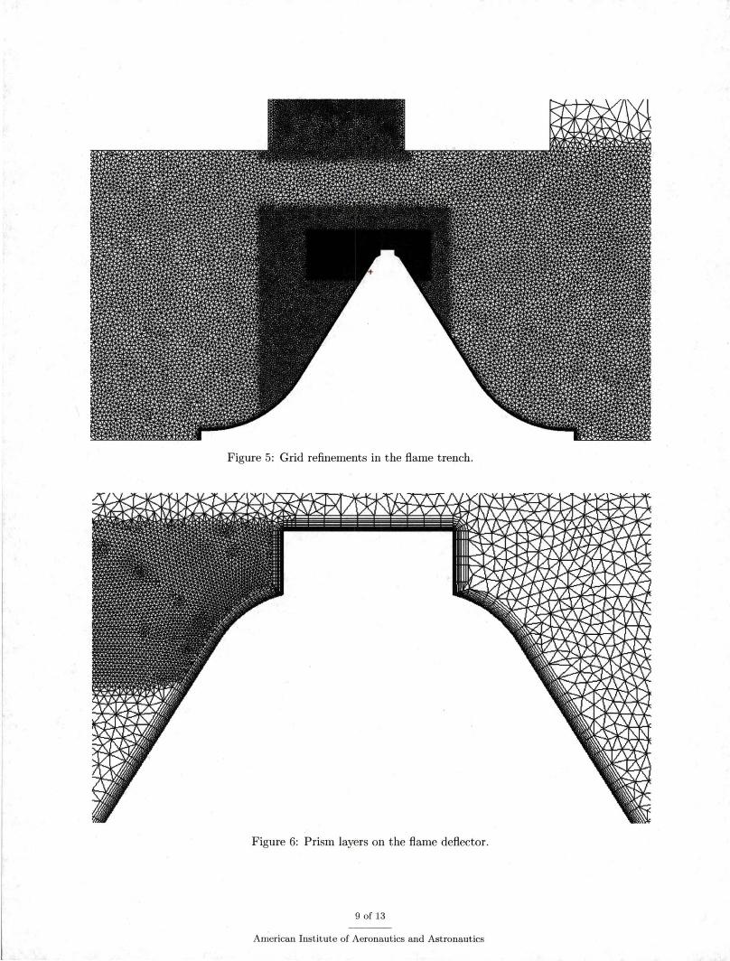
Figure 5: Grid refinements in the flame trench.
Figure 6: Prism layers on the flame deflector.
9 of 13
American Institute of Aeronautics and Astronautics
4.84478+00
3.6757&+00
2.9066&+00
1.93798+00
9.8693&-01
0.0000&+00
4.84478+00
3.67578+00
2.90688+00
1.93798+00
9.8893&-01
0.00008+00
Figure 7: Mach number contours in the SRB and SSME cross sections.
10 of 13
American Institute of Aeronautics and Astronautics
T
4.00008+03
3.25608+03
2.51208+03
1.76608+03
1.02408+03
2.60008+02
T
4.00008+03
3.25608+03
2.51208+03
1.76608+03
1.02408+03
2.60008+02
Figure 8: Temperature contours (unit of Kelvin) in the SRB and SSME cross sections.
11 of 13
American Institute of Aeronautics and Astronautics

HZO
1.00008+00
6.0000e-01
6.0000e-01
.t.OOOOe-01
Z.OOOOe-01
0.00008+00
HZO
1.00008+00
B.OOOOe-01
6.0000e-01
.t.OOOOe-01
Z.OOOOe-01
0.00008+00
Figure 9: Water vapor mass fraction in the SRB and SSME cross sections.
T
4.0000e+03
3.ZS60e+03
Z.S1Z0e+03
1.76808+03
1.0Z40e+03
Z.8000e+OZ
Figure 10: Surface temperature contours (unit of Kelvin) on the MFD (top view).
12 of 13
American Institute of Aeronautics and Astronautics
EDP _Denslty1
2.00008+02
1.60008+02
1.2000e+02
6.00008+01
-4.00008+01
O.OOOOe+OO
Figure 11: EDP density near the water jet and SRB.
Deflector Surface Temperature
- Water-Off (13M cells)
----Water-On (13M cells)
······· Water-On (34M cells)
-Deflector
-15 -10 -5 o x (m) 5 10 15
Figure 12: Surface temperature near the SRB cross section.
13 of 13
American Institute of Aeronautics and Astronautics
0
-5
-10
-15
-20
-25
-30
20