Embed Size (px)
Citation preview
IPASJ International Journal of Mechanical Engineering (IIJME) Web Site: http://www.ipasj.org/IIJME/IIJME.htm
A Publisher for Research Motivation ........ Email:[email protected] Volume 5, Issue 4, April 2017 ISSN 2321-6441
Volume 5, Issue 4, April 2017 Page 13
ABSTRACT The purpose of this project is to design and fabricate the economic machine for small sized sheet metal products. Conventionally for production of these products large machines are used which are not cost economical. Also there is a loss of energy due to friction. The objective of this project is to reduce the energy consumption, cost and to perform the various forming operations on a single machine. The solution is obtained with the implementation of ‘Electromagnet’. Since the actuation is electrically assisted the operation is frictionless and accurate. The punching force is controlled by varying current using ‘DIMMER’ circuit. The power is consumed only during the punching stroke resulting into efficient operation. After successful fabrication, the set up was tested and optical testing is done for any defects in the punched samples. Keywords: Sheet Metal, Friction, Energy, Forming, Electromagnet, Punching, DIMMER, Optical testing
1. INTRODUCTION Sheet metal industry is one of the vast and rapidly growing industries. The intense researches are going on to develop more efficient and economical machines to carry out sheet metal forming operations. Conventionally, the machines used are mechanical press, hydraulic press, pneumatic press etc. These machines are often large in construction as compared to the product to be manufactured. Also there is a loss of energy due to friction. To overcome the disadvantages of conventional machine we implemented new concept based on ‘Electromagnetism’. With help of electromagnet the punch plate is made to move for punching operation. Various operations like punching, embossing, notching, slitting, perforating, bending can be performed on thin sheets of metal sheet, card board, asbestos, paper, foam, plastic etc. The required force for any operation can be obtained by controlling the power. We provide the ‘DIMER’ circuit for controlling the power. The capacity of machine depends upon the size and the number of coils of an electromagnet.
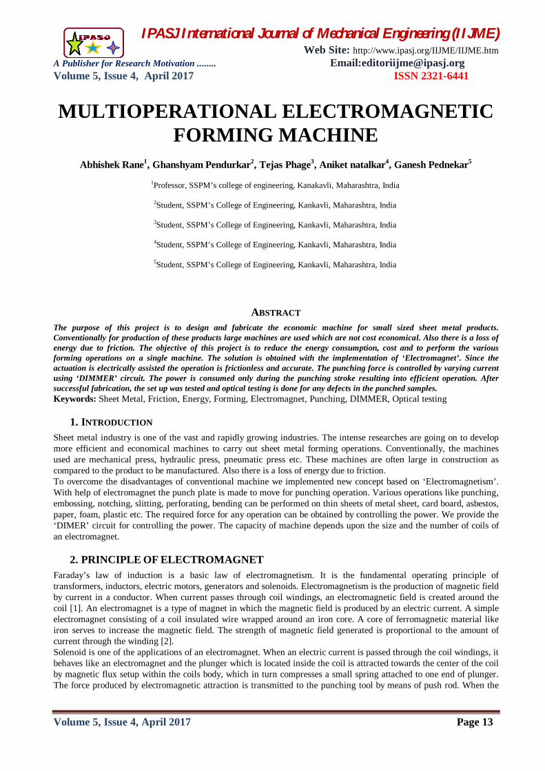
2. PRINCIPLE OF ELECTROMAGNET Faraday’s law of induction is a basic law of electromagnetism. It is the fundamental operating principle of transformers, inductors, electric motors, generators and solenoids. Electromagnetism is the production of magnetic field by current in a conductor. When current passes through coil windings, an electromagnetic field is created around the coil [1]. An electromagnet is a type of magnet in which the magnetic field is produced by an electric current. A simple electromagnet consisting of a coil insulated wire wrapped around an iron core. A core of ferromagnetic material like iron serves to increase the magnetic field. The strength of magnetic field generated is proportional to the amount of current through the winding [2]. Solenoid is one of the applications of an electromagnet. When an electric current is passed through the coil windings, it behaves like an electromagnet and the plunger which is located inside the coil is attracted towards the center of the coil by magnetic flux setup within the coils body, which in turn compresses a small spring attached to one end of plunger. The force produced by electromagnetic attraction is transmitted to the punching tool by means of push rod. When the
MULTIOPERATIONAL ELECTROMAGNETIC FORMING MACHINE
Abhishek Rane1, Ghanshyam Pendurkar2, Tejas Phage3, Aniket natalkar4, Ganesh Pednekar5
1Professor, SSPM’s college of engineering, Kanakavli, Maharashtra, India
2Student, SSPM’s College of Engineering, Kankavli, Maharashtra, India
3Student, SSPM’s College of Engineering, Kankavli, Maharashtra, India
4Student, SSPM’s College of Engineering, Kankavli, Maharashtra, India
5Student, SSPM’s College of Engineering, Kankavli, Maharashtra, India
IPASJ International Journal of Mechanical Engineering (IIJME) Web Site: http://www.ipasj.org/IIJME/IIJME.htm
A Publisher for Research Motivation ........ Email:[email protected] Volume 5, Issue 4, April 2017 ISSN 2321-6441
Volume 5, Issue 4, April 2017 Page 14
supply of current is turned OFF the electromagnetic field generated previously by the coil collapses and energy stored in compressed spring forces the plunger back to its original rest position [1].
Figure 1 Construction of Solenoid [1]
3. DESIGN METHODOLOGY
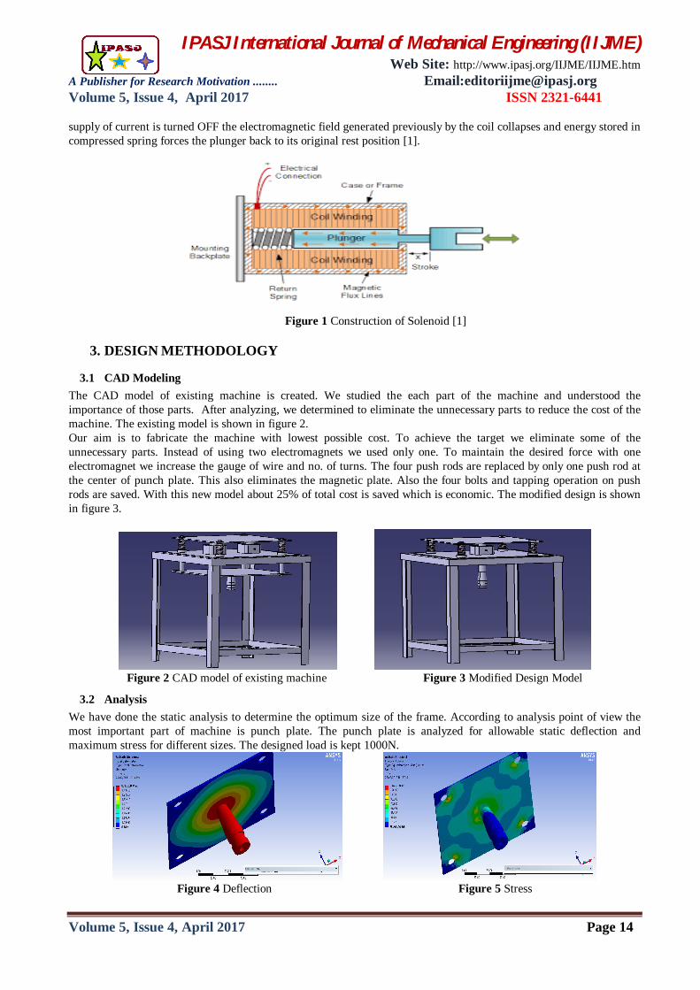
3.1 CAD Modeling The CAD model of existing machine is created. We studied the each part of the machine and understood the importance of those parts. After analyzing, we determined to eliminate the unnecessary parts to reduce the cost of the machine. The existing model is shown in figure 2. Our aim is to fabricate the machine with lowest possible cost. To achieve the target we eliminate some of the unnecessary parts. Instead of using two electromagnets we used only one. To maintain the desired force with one electromagnet we increase the gauge of wire and no. of turns. The four push rods are replaced by only one push rod at the center of punch plate. This also eliminates the magnetic plate. Also the four bolts and tapping operation on push rods are saved. With this new model about 25% of total cost is saved which is economic. The modified design is shown in figure 3.
Figure 2 CAD model of existing machine Figure 3 Modified Design Model
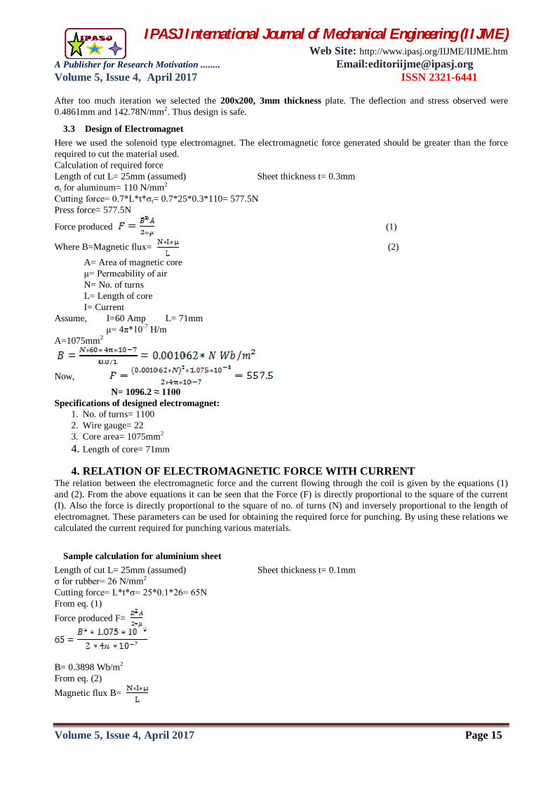
3.2 Analysis We have done the static analysis to determine the optimum size of the frame. According to analysis point of view the most important part of machine is punch plate. The punch plate is analyzed for allowable static deflection and maximum stress for different sizes. The designed load is kept 1000N.
Figure 4 Deflection Figure 5 Stress
IPASJ International Journal of Mechanical Engineering (IIJME) Web Site: http://www.ipasj.org/IIJME/IIJME.htm
A Publisher for Research Motivation ........ Email:[email protected] Volume 5, Issue 4, April 2017 ISSN 2321-6441
Volume 5, Issue 4, April 2017 Page 15
After too much iteration we selected the 200x200, 3mm thickness plate. The deflection and stress observed were 0.4861mm and 142.78N/mm2. Thus design is safe.
3.3 Design of Electromagnet Here we used the solenoid type electromagnet. The electromagnetic force generated should be greater than the force required to cut the material used. Calculation of required force Length of cut L= 25mm (assumed) Sheet thickness t= 0.3mm σt for aluminum= 110 N/mm2
Cutting force= 0.7*L*t*σt= 0.7*25*0.3*110= 577.5N Press force= 577.5N
Force produced (1)
Where B=Magnetic flux= (2)
A= Area of magnetic core μ= Permeability of air N= No. of turns L= Length of core I= Current Assume, I=60 Amp L= 71mm μ= 4π*10-7 H/m A=1075mm2
Now,
N= 1096.2 ≈ 1100 Specifications of designed electromagnet:
1. No. of turns= 1100 2. Wire gauge= 22 3. Core area= 1075mm2 4. Length of core= 71mm
4. RELATION OF ELECTROMAGNETIC FORCE WITH CURRENT The relation between the electromagnetic force and the current flowing through the coil is given by the equations (1) and (2). From the above equations it can be seen that the Force (F) is directly proportional to the square of the current (I). Also the force is directly proportional to the square of no. of turns (N) and inversely proportional to the length of electromagnet. These parameters can be used for obtaining the required force for punching. By using these relations we calculated the current required for punching various materials.
Sample calculation for aluminium sheet Length of cut L= 25mm (assumed) Sheet thickness t= 0.1mm σ for rubber= 26 N/mm2
Cutting force= L*t*σ= 25*0.1*26= 65N From eq. (1) Force produced F=
B= 0.3898 Wb/m2
From eq. (2) Magnetic flux B=
IPASJ International Journal of Mechanical Engineering (IIJME) Web Site: http://www.ipasj.org/IIJME/IIJME.htm
A Publisher for Research Motivation ........ Email:[email protected] Volume 5, Issue 4, April 2017 ISSN 2321-6441
Volume 5, Issue 4, April 2017 Page 16
I= 20.97 Amp
4.2 Values of current for different materials Table 1: For Aluminium sheet (Shear strength= 180N/mm2)
Length of cut 25 25 25 Sheet thickness 0.1 0.2 0.3 Cutting force 450 900 1350 Value of current 55.18 78.03 95.56
Table 2: For Plastic sheet (Shear strength= 90N/mm2) Length of cut 25 25 25 Sheet thickness 0.1 0.2 0.3 Cutting force 225 450 675 Value of current 39.2 55.18 67.58
Table 3: For Rubber sheet (Shear strength= 26N/mm2) Length of cut 25 25 25 Sheet thickness 0.1 0.2 0.3 Cutting force 65 130 195 Value of current 20.97 29.65 36.32
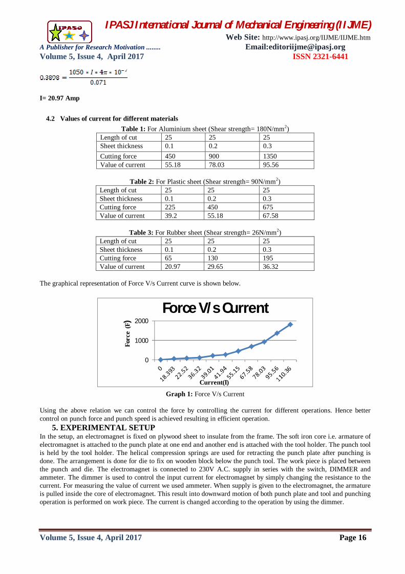
The graphical representation of Force V/s Current curve is shown below.
0
1000
2000
Forc
e (F
)
Current(I)
Force V/s Current
Graph 1: Force V/s Current
Using the above relation we can control the force by controlling the current for different operations. Hence better control on punch force and punch speed is achieved resulting in efficient operation.
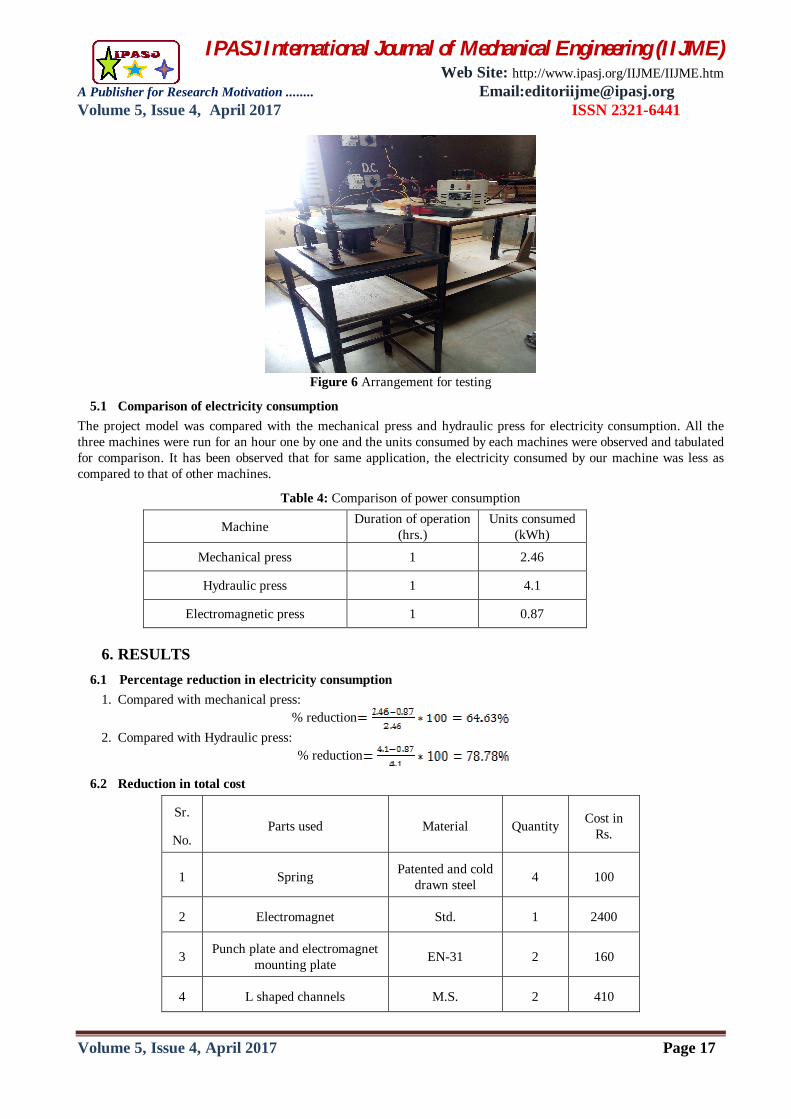
5. EXPERIMENTAL SETUP In the setup, an electromagnet is fixed on plywood sheet to insulate from the frame. The soft iron core i.e. armature of electromagnet is attached to the punch plate at one end and another end is attached with the tool holder. The punch tool is held by the tool holder. The helical compression springs are used for retracting the punch plate after punching is done. The arrangement is done for die to fix on wooden block below the punch tool. The work piece is placed between the punch and die. The electromagnet is connected to 230V A.C. supply in series with the switch, DIMMER and ammeter. The dimmer is used to control the input current for electromagnet by simply changing the resistance to the current. For measuring the value of current we used ammeter. When supply is given to the electromagnet, the armature is pulled inside the core of electromagnet. This result into downward motion of both punch plate and tool and punching operation is performed on work piece. The current is changed according to the operation by using the dimmer.
IPASJ International Journal of Mechanical Engineering (IIJME) Web Site: http://www.ipasj.org/IIJME/IIJME.htm
A Publisher for Research Motivation ........ Email:[email protected] Volume 5, Issue 4, April 2017 ISSN 2321-6441
Volume 5, Issue 4, April 2017 Page 17
Figure 6 Arrangement for testing
5.1 Comparison of electricity consumption The project model was compared with the mechanical press and hydraulic press for electricity consumption. All the three machines were run for an hour one by one and the units consumed by each machines were observed and tabulated for comparison. It has been observed that for same application, the electricity consumed by our machine was less as compared to that of other machines.
Table 4: Comparison of power consumption
Machine Duration of operation (hrs.)
Units consumed (kWh)
Mechanical press 1 2.46
Hydraulic press 1 4.1
Electromagnetic press 1 0.87
6. RESULTS
6.1 Percentage reduction in electricity consumption 1. Compared with mechanical press:
% reduction 2. Compared with Hydraulic press:
% reduction
6.2 Reduction in total cost
Sr.
No. Parts used Material Quantity Cost in
Rs.
1 Spring Patented and cold drawn steel 4 100
2 Electromagnet Std. 1 2400
3 Punch plate and electromagnet mounting plate EN-31 2 160
4 L shaped channels M.S. 2 410
IPASJ International Journal of Mechanical Engineering (IIJME) Web Site: http://www.ipasj.org/IIJME/IIJME.htm
A Publisher for Research Motivation ........ Email:[email protected] Volume 5, Issue 4, April 2017 ISSN 2321-6441
Volume 5, Issue 4, April 2017 Page 18
5 Rod M.S. 1 100
6 Punch tools and die HCHCr 5 2200
7 Metal strip 12x3mm M.S. 1 100
8 Plywood 15mm thick Wood 1 100
9 Plywood 4mm thick Wood 1 50
10 Electrical components Std. - 250
11 Nuts, Bolts and Accessories Std. - 200
12 Fabrication expenses - - 400
Total 6470
The reduction in cost of the machine is achieved so it can be used for small scale industry economically.
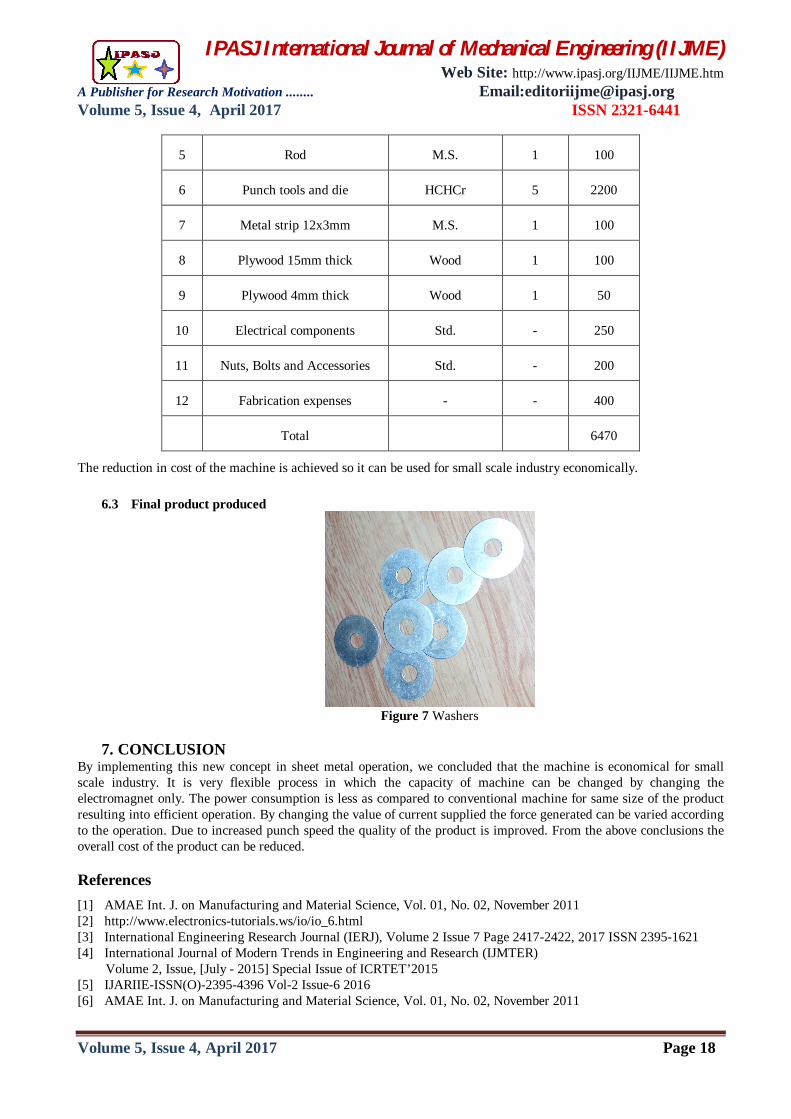
6.3 Final product produced
Figure 7 Washers
7. CONCLUSION
By implementing this new concept in sheet metal operation, we concluded that the machine is economical for small scale industry. It is very flexible process in which the capacity of machine can be changed by changing the electromagnet only. The power consumption is less as compared to conventional machine for same size of the product resulting into efficient operation. By changing the value of current supplied the force generated can be varied according to the operation. Due to increased punch speed the quality of the product is improved. From the above conclusions the overall cost of the product can be reduced.
References [1] AMAE Int. J. on Manufacturing and Material Science, Vol. 01, No. 02, November 2011 [2] http://www.electronics-tutorials.ws/io/io_6.html [3] International Engineering Research Journal (IERJ), Volume 2 Issue 7 Page 2417-2422, 2017 ISSN 2395-1621 [4] International Journal of Modern Trends in Engineering and Research (IJMTER) Volume 2, Issue, [July - 2015] Special Issue of ICRTET’2015 [5] IJARIIE-ISSN(O)-2395-4396 Vol-2 Issue-6 2016 [6] AMAE Int. J. on Manufacturing and Material Science, Vol. 01, No. 02, November 2011
IPASJ International Journal of Mechanical Engineering (IIJME) Web Site: http://www.ipasj.org/IIJME/IIJME.htm
A Publisher for Research Motivation ........ Email:[email protected] Volume 5, Issue 4, April 2017 ISSN 2321-6441
Volume 5, Issue 4, April 2017 Page 19
[7] International Journal on Recent and Innovation Trends in Computing and Communication Volume: 4 Issue: 4 ISSN: 2321-8169 354 – 356
[8] www.ijetae.com (ISSN 2250-2459, ISO 9001:2008 Certified Journal, Volume 5, Issue 4, April 2015) [9] www.ijmer.com (IJMER ISSN: 2249–6645 Vol. 5, Iss. 7, July 2015, 30) [10] International Journal of Modern Trends in Engineering and Research (IJMTER) Volume 2, Issue, [July - 2015] Special Issue of ICRTET’2015 [11] International Journal of Engineering Technology Science and Research IJETSR www.ijetsr.com ISSN 2394 –
3386 Volume 2 Issue 2 February 2015 AUTHOR
Abhishek Rane received the B.E. degree in Automobile Engineering from Rajendra Mane College of Engineering and Technology in 2009. He completed the M.E. in Machine Design-Mechanical from FAMT, Ratnagiri in 2017.


![Effect of electromagnetic bulging on fatigue …to the high strain rate of electromagnetic forming (which is estimated to be in the range of 103−104 s−1) [4,7], similar results](https://img.pdfslide.us/doc/110x75/5e690dd171140c3900006f63/effect-of-electromagnetic-bulging-on-fatigue-to-the-high-strain-rate-of-electromagnetic.jpg)